Experimental Science P5: Oscilloscope. Sensitivity ... - JGLG
Experimental Science P5: Oscilloscope. Sensitivity ... - JGLG
Experimental Science P5: Oscilloscope. Sensitivity ... - JGLG

Create successful ePaper yourself
Turn your PDF publications into a flip-book with our unique Google optimized e-Paper software.
<strong>Experimental</strong> <strong>Science</strong><br />
<strong>P5</strong>: <strong>Oscilloscope</strong>. <strong>Sensitivity</strong>, resolution and maximum device error.<br />
Vers. 1.0 2010/10/28<br />
_________________________________________________________________________<br />
1. Purpose<br />
• Initiation to the oscilloscope.<br />
• Estimate the sensitivity, resolution and the maximum device error.<br />
2. Introduction<br />
An oscilloscope (from Latin: oscillare, oscillate + skopein, see) is a device that allows the<br />
visualisation of the variation of periodic (or repetitive) voltage signals with time. You could<br />
say it’s an improved voltmeter: besides showing voltage it allows the measurement of time<br />
intervals.<br />
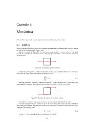
Its screen is a rectangle (10 cm wide by 8 cm high) which is divided into 1 cm squares<br />
(see oscilloscope pictures at the top of pages 3 to 7). However, at the central axes of this<br />
grid there are smaller 2 mm divisions.<br />
The oscilloscope is a transducer that can be summed up by the following diagram:<br />
in which x is the voltage U (or time interval T) and y is the corresponding displacement of the<br />
screen’s luminous dot.<br />
All measurements in an oscilloscope come down to basic grid distance<br />
measurements.<br />
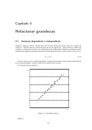
If we intend to measure a voltage, the first step will be to find out how many Volts<br />
each grid centimetre is worth. This quantity is the scale factor. By changing the scale factor<br />
we are changing the device’s sensitivity:<br />
<strong>Sensitivity</strong> = ∆d/∆U = 1/(scale factor)<br />
For instance, if I measured 2.4 cm in the grid and the scale selector knob indicates a<br />
scale factor of 5 V/cm, then the reading will be:<br />
U = 5 V/cm x (2.4 ± 0.1) cm = (12.0 ± 0.5) V<br />
1/7
Vers. 1.0 2010/10/28<br />
If we intend to measure a time interval then we must know how many seconds each<br />
grid centimetre is worth.<br />
For instance, if I measured 3.2 cm in the grid and the scale selector knob indicates a<br />
scale factor of 2 ms/cm, then the reading will be:<br />
3. Additional information<br />
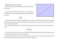
over time:<br />
T = 2 ms/cm x (3.2 ± 0.1) cm = (6.4 ± 0.2) ms<br />
Graphical representation of a sinusoidal signal with amplitude A and period T variation<br />
Equation:<br />
4. <strong>Experimental</strong> activity<br />
4.1 Material<br />
1 oscilloscope, 1 signal generator, 1 voltage supply, 1 battery, oscilloscope probes,<br />
connection wires, screwdriver, crocodiles.<br />
4.2 <strong>Experimental</strong> procedure<br />
Read the following text and follow the indicated instructions.<br />
On each page there is an image of an oscilloscope where you should write your own<br />
comments about each button, knob or selector used at that page.<br />
Whenever you have to make a reading be sure to always use the most sensitive scale<br />
and to make the measurement where there are 2 mm divisions.<br />
Always ask the teacher to confirm your measurements. Try to always organize your<br />
measurement results into tables. For each measurement, besides recording the unit you<br />
should take the maximum device error, the sensitivity as well as the resolution.<br />
2/7
4.2.1. Inputs<br />
a) Identify the following inputs:<br />
A or I – channel A (or I) BNC input (British Naval Connector)<br />
B or II – channel B (or II) BNC input<br />
EXT – external trigger control input<br />
4.2.2. Outputs<br />
a) Identify the following outputs:<br />
Screen: - 10 cm x 8 cm<br />
- divided into 1 x 1 cm squares<br />
- has smaller 0.2 cm divisions at the grid’s central axes<br />
CAL – square signal output with 1V peak-to-peak<br />
4.2.3. Controls<br />
4.2.3.1 Initial checks<br />
a) Connect the oscilloscope to a power outlet (220 V - 50 Hz)<br />
b) Push the POWER button<br />
Vers. 1.0 2010/10/28<br />
c) Turn all the knobs with the CAL label to the factory calibration position (CAL)<br />
d) Select the ground (GND) input mode. Align the sweep line with one of the<br />
horizontal grid lines. That grid line will be the 0 V reference line. Repeat for both<br />
input channels.<br />
e) Set the trigger mode to AUTO<br />
f) If necessary, use the screwdriver to adjust the TRACE ROTATION screw until the<br />
sweep line is aligned with the grid’s horizontal lines. Repeat step d).<br />
g) Connect one oscilloscope probe from the first channel to the CAL output.<br />
h) Select the DC input mode.<br />
i) Verify that the measured signal coincides with the nominal calibration signal. Don’t<br />
forget to use the appropriate scale factor and record your measurements.<br />
3/7
4.2.3.2 Screen controls<br />
a) Test each of these parameters and verify their function:<br />
INTENS - controls the intensity of the sweep line<br />
Vers. 1.0 2010/10/28<br />
FOCUS – controls the electrons beam convergence towards the screen. It is<br />
used to make the sweep trace sharper.<br />
TRACE ROTATION – controls the direction of the sweep trace. The sweep<br />
trace should be parallel to the grid’s horizontal lines.<br />
ILLUM – Offers the possibility of a backlight screen. It should be used when<br />
measurements are made in low light conditions or to take screen<br />
pictures.<br />
4/7
Vers. 1.0 2010/10/28<br />
4.2.4 Vertical deflection control<br />
a) Identify the following controls:<br />
AMP/DIV - Outer: deflection coefficient selector from 5 mV/div to 5 V/div<br />
- Inner: deflection coefficient re-calibrator. Should be at the CAL<br />
position for the factory calibration.<br />
- When the inner deflection control is pulled the vertical deflection<br />
coefficient increases by a factor of 5.<br />
b) Use the first channel probe to measure the battery voltage. Use the second channel<br />
probe to measure and set a different voltage at the voltage supply. Record the<br />
measurements in a table. Extend the table by adding three different voltage supply<br />
output values.<br />
c) Make sure that for a 0 V input the measured value is in fact 0 V (zero adjust). How can<br />
a zero adjust be made without disconnecting the probe from the voltage supply?<br />
d) Connect one of the probes to the oscilloscope’s CAL output signal and pull the inner<br />
vertical deflection control. What happened? Reconnect the probes as they were at b).<br />
e) Test each of the following parameters:<br />
POSITION – controls the vertical position of the sweep line.<br />
AC GND DC – input connection selector:<br />
AC – on this operation mode any constant signal component is removed<br />
DC – the input signal is directly connected to the vertical deflection<br />
plates<br />
GND – the vertical deflection plates are short-circuited<br />
A ADD B – visible channels selector:<br />
A – only the A channel is visible<br />
B – only the B channel is visible<br />
DUAL – both channels A and B are visible<br />
0.2 µs/div – 0.5 ms/div – ALT mode; 1 ms/div – 0.5 s/div – CHOP<br />
mode<br />
ADD – displays A+B or A-B<br />
5/7
4.2.5 Horizontal deflection control<br />
a) Identify the following controls:<br />
Vers. 1.0 2010/10/28<br />
MTB TIME/DIV - Outer: main time base deflection coefficient (sweep speed)<br />
selector from 0.2 µs/div – 0.5 ms/div<br />
MTB – main time base selector<br />
X DEFL – a complete counter clockwise rotation of the MTB TIME/DIV<br />
selector sets the X-Y mode<br />
MTB VAR – main time base re-calibrator<br />
b) Connect the 10x selected probe to the CAL oscilloscope output. Change the probe to the<br />
1x setting and pull the x-position knob. What happened?<br />
c) Reset the x-position knob to the original position and set the probe back to 10x. What<br />
happened?<br />
d) Remove the voltage supply connections. Connect the signal generator output to the A<br />
channel oscilloscope input. Measure the sinusoidal signal amplitude and period. Repeat<br />
for 4 different sets of amplitude and period. Organize your results into a table.<br />
6/7
4.2.6 Trigger system<br />
a) Identify the following oscilloscope controls:<br />
Vers. 1.0 2010/10/28<br />
AUTO – The sweep is automatic and takes place even when there is no signal.<br />
TRIG – The sweep only happens when two criteria are met: The voltage level<br />
is greater than a preset value and the voltage slope over time has a preset sign<br />
(+/-).<br />
SINGLE – Only a single sweep happens.<br />
LEVEL – Voltage level selector. When the input voltage is larger a sweep is<br />
triggered.<br />
SLOPE – slope sign selector (can take only two possible values: + or -).<br />
SOURCE – trigger signal source selector used to evaluate if a sweep should<br />
be triggered (level and slope criteria are met). There are 4 possible sources:<br />
A – the A channel<br />
B – the B channel<br />
EXT – an external signal is applied to the "EXT" input<br />
LINE – the AC network power (220 V, 50 Hz)<br />
b) In the AUTO trigger mode, connect channels A and B to two independent signals (use the<br />
signal generator and the CAL signal output). Observe both signals simultaneously. Watch<br />
what happens when different trigger sources are selected (A, B, EXT or LINE). Record<br />
the signal shapes (with scale factors). Explain what you observe.<br />
c) Change to the TRIG mode and see what happens at the sweep beginning. What is the<br />
sweep initiation voltage level? What is the slope sign? Rotate the LEVEL knob and<br />
explain what you observe. Pull or push the knob and explain what you observe.<br />
7/7