Series CN / CNF / CNK - HERMETIC-Pumpen GmbH
Series CN / CNF / CNK - HERMETIC-Pumpen GmbH
Series CN / CNF / CNK - HERMETIC-Pumpen GmbH

You also want an ePaper? Increase the reach of your titles
YUMPU automatically turns print PDFs into web optimized ePapers that Google loves.
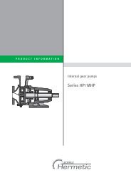
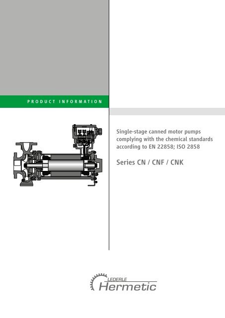
PRODUCT INFORMATION<br />
Single-stage canned motor pumps<br />
complying with the chemical standards<br />
according to EN 22858; ISO 2858<br />
<strong>Series</strong> <strong>CN</strong> / <strong>CN</strong>F / <strong>CN</strong>K
Contents<br />
Description .......................................... 2<br />
Application and use ............................. 4<br />
Materials ............................................. 5<br />
Functional principle ............................ 6<br />
Design options .................................... 9<br />
Monitoring equipment ......................... 10<br />
Characteristics diagram ....................... 12<br />
2<br />
Description<br />
General<br />
Canned motor pumps are characterised by a compact,<br />
integrated unit without mechanical seal. The motor and<br />
pump form a unit with the rotor and the impeller fitted<br />
onto a common shaft. The rotor is guided by two identical,<br />
liquid-lubricated slide bearings. The stator winding of the<br />
motor is separated from the rotor chamber by means of a<br />
thin stator liner. In conjunction with the hydraulic section<br />
of the pump, the rotor chamber itself provides a combined<br />
cavity which needs to be filled with liquid to be conveyed<br />
prior to the start-up of the pump. The heat losses of the<br />
motor are dissipated by a partial flow between the rotor and<br />
the stator. At the same time, the partial flow lubricates both<br />
slide bearings in the rotor chamber. Both the stator liner,<br />
which is a hermetically sealed component, and the motor<br />
casing are used as safety containments. Because of that,<br />
canned motor pumps always ensure highest safety level<br />
when conveying dangerous, toxic, explosive and valuable<br />
liquids.<br />
impeller discharge nozzle rotor stator motor casing<br />
(secondary containment)<br />
suction nozzle slide bearings stator liner<br />
(primary containment)
Function<br />
<strong>CN</strong><br />
The partial flow for cooling the motor and lubricating<br />
the slide bearings will be deverted at the periphery of the<br />
impeller and, after having passed through the motor, is<br />
recirculated through the hollow shaft to the suction side<br />
of the impeller. This design is suitable for the delivery<br />
of uncritical liquids at low vapour pressures.<br />
<strong>CN</strong>F<br />
The partial flow for cooling the motor and lubricating<br />
the slide bearings will be diverted at the periphery of the<br />
impeller and, after having passed through the motor, is<br />
recirculated to the discharge side. An auxiliary impeller is<br />
used to overcome the hydraulic losses encountered along<br />
the way. The recirculation of the partial flow towards<br />
discharge side ensures that the heated motor cooling flow<br />
has sufficient excess pressure above the boiling point of the<br />
pumped liquid during re-entry into the pump. This pump<br />
design can be used for liquefied gases with an extremely<br />
steep vapour pressure curve.<br />
<strong>CN</strong>K<br />
The liquid is delivered from the suction side through the<br />
impeller to the discharge side. A thermal barrier avoids the<br />
direct heat transfer from the pump to the motor part. The<br />
motor heat losses are dissipated by a secondary cooling /<br />
lubricating circuit via a separate heat exchanger. This<br />
cooling / lubricating circuit also supplies the slide bearings.<br />
Thus the liquids at temperatures up to +400 °C can be<br />
conveyed while the secondary cooling cycle is at a lower<br />
temperature level. This construction is also suitable for<br />
conveying polluted or particle-containing liquids. If applicable,<br />
pure process liquid needs to be injected into the motor<br />
circuit.<br />
3<br />
Recirculation of partial flow to suction side<br />
Recirculation of partial flow to discharge side<br />
Internal cooling / lubricating circuit
Application and use<br />
Fields of application<br />
<strong>CN</strong><br />
For the delivery of aggressive, toxic, explosive, precious,<br />
inflammable, radioactive and slightly volatile liquids e. g.<br />
sulfuric acid, nitric acid, hydrofluoric acid, hydrocyanic acid,<br />
ethanoic acid, formic acid, NaOH, KOH, D 2 O solvent, etc.<br />
<strong>CN</strong>F<br />
Liquefied gases, e. g. ammonia, freons, carbon dioxide,<br />
amines, propane, butane, vinyl chloride, ethylene oxide,<br />
chlorine, phosgene, propylene, carbon bisulphide,<br />
hydrocarbon, diphenyl (> 250 °C) etc.<br />
<strong>CN</strong>K<br />
For the delivery of hot organic heat transfer oil, as well<br />
as heating bath liquids. This design can also be used<br />
for aggressive, toxic, explosive, precious, inflammable,<br />
radioactive and slightly volatile liquids.<br />
Application ranges<br />
<strong>CN</strong>: –120 °C to +360 °C<br />
<strong>CN</strong>F: –120 °C to +360 °C<br />
<strong>CN</strong>K: –120 °C to +400 °C<br />
Canned motors<br />
Power: up to 300 kW at 1450 rpm [50 Hz]<br />
up to 400 kW at 2900 rpm [50 Hz]<br />
up to 336 kW at 1750 rpm [60 Hz]<br />
up to 448 kW at 3500 rpm [60 Hz]<br />
Operation: S1<br />
Voltage: 400 / 690 V<br />
(additional tensions possible)<br />
Insulation class: H-180<br />
C-220 / C-400<br />
Frequency: 50 or 60 Hz<br />
(also suitable for operation with<br />
frequency converter)<br />
Degree of protection: IP 67<br />
Motor protection: PTC thermistor e.g.<br />
KL180 (for H winding)<br />
KL210 (for C-220 winding)<br />
alternative Pt100 resistance<br />
thermometer (for all windings)<br />
4<br />
Pump and hydraulic denomination<br />
e. g.<br />
<strong>CN</strong> 40 – 25 – 160<br />
impeller diameter in mm<br />
discharge nozzle diameter in mm<br />
suction nozzle diameter in mm<br />
series<br />
Explosion protection according to Directive 94/9/EC<br />
incl. EC-type-examination certificate<br />
Marking: II 2 G Ex de IIC T1 to T6 (* )<br />
(*) Due to explosion protection requirements, the<br />
following restrictions apply to the explosion group:<br />
Thickness of coating > 200 μm – explosion group IIB<br />
Thickness of coating ≤ 200 μm – explosion group IIC<br />
Documentation according to <strong>HERMETIC</strong>-Standard<br />
■■ instruction manual incl. instructions for<br />
commissioning, operation and maintenance<br />
■■ technical specification<br />
■■ sectional drawing with position numbers<br />
■■ dimensional drawing<br />
■■ spare part list with order numbers<br />
■■ test report<br />
■■ test performance curve<br />
■■ EC Declaration of Conformity<br />
Inspections and guarantees<br />
Standard inspections<br />
Hydraulic inspection:<br />
■■ each pump is subjected to a test run and the operating<br />
point is guaranteed according to ISO 9906 – class 2<br />
(5 measuring points)<br />
■■ pressure test<br />
■■ axial thrust measurement<br />
■■ leakage test<br />
Additional inspections<br />
The following inspections can be carried out and certified<br />
at additional cost (e. g. NPSH test, Helium leakage test,<br />
vibration test, ultrasonic test, PMI test). Any further inspections<br />
and tests are specified in the technical specification. The<br />
guarantees are effected according to the valid conditions<br />
of supply.
Materials<br />
Materials and pressure ratings<br />
VDMA-no. description series <strong>CN</strong> / <strong>CN</strong>F / <strong>CN</strong>K<br />
material S1 material S2 material C<br />
pressure rating PN 25 pressure rating PN 25 pressure rating PN 16<br />
wetted parts<br />
102 volute casing JS 1025 1.0619+N 1.4408<br />
161 casing cover 1.0570/1.0460 1.0570/1.0460 1.4571<br />
230.01 impeller JL 1040 / JS 1025 JL 1040 / JS 1025 1.4408<br />
230.03 auxiliary impeller (1) JL 1030 JL 1030 1.4581<br />
344 bearing support lantern 1.0570 / 1.0460 1.0570 / 1.0460 1.4571<br />
360 bearing cover 1.0570 / 1.0460 1.0570 / 1.0460 1.4571<br />
472.01/02 slide ring PTFE/K PTFE/K PTFE/K<br />
513 wear ring insert JL 1030 JL 1030 1.4571<br />
529.01/02 bearing sleeve 1.4571/W5 (2) 1.4571/W5 (2) 1.4571/W5 (2)<br />
545.01/02 bearing bushing 1.4571/SiC30 1.4571/SiC30 1.4571/SiC30<br />
816 stator liner Hastelloy C4 Hastelloy C4 Hastelloy C4<br />
817 rotor liner 1.4571 1.4571 1.4571<br />
819 shaft 1.4571 1.4571 1.4571<br />
non-wetted parts<br />
811 motor casing 1.0254 1.0254 1.0254<br />
special materials / higher pressure ratings are possible on demand<br />
(1) parts only for <strong>CN</strong>F and <strong>CN</strong>K<br />
(2) high velocity tungsten carbide coating<br />
Pressure and temperature limits<br />
25<br />
20<br />
max. 18,5<br />
allowable 16<br />
working<br />
15<br />
pressure<br />
[bar]<br />
10<br />
5<br />
0<br />
material S1, S2 and C<br />
S 1<br />
C C<br />
S 2<br />
–120 –40 –10<br />
120<br />
360<br />
–100 –50 0 50 100 150 200 250 300 350 400<br />
5<br />
liquid temperature [°C]<br />
S 1<br />
S 2
Functional principle<br />
<strong>CN</strong><br />
<strong>CN</strong>F<br />
<strong>CN</strong>Kp<br />
6
Bearings<br />
The hermetically sealed design requires the arrangement<br />
of the bearings within the pumped liquid. Therefore, only<br />
hydrodynamic slide bearings are used in most cases. During<br />
normal operation slide bearings have the advantage that<br />
there is no contact between the sliding surfaces of the<br />
bearing. In continuous operation, they are wear- and<br />
maintenance-free. Service life of 8 to 10 years can be<br />
easily achieved by using hermetically sealed pumps.<br />
The almost universal bearing combination materials based<br />
on tungsten carbide (W5) and silicon carbide (SiC30) have<br />
proven to be the best choice. These combinations consist of a<br />
metallic shaft sleeve made of stainless steel (1.4571) coated<br />
bearing sleeve<br />
(1.4571/W5)<br />
shaft<br />
slide ring<br />
7<br />
with tungsten carbide by means of a “High Velocity Oxygen<br />
Fuel“ process and a fixed bearing bushing made of ceramic<br />
material (SiC30) that is surrounded by a sleeve made of<br />
stainless steel. SiC30 is a mixed material of silicon carbide<br />
and graphite, combining the product advantages of both<br />
materials. Conditions of mixed friction, as they may arise for<br />
example during start-up and stopping of the pump, can be<br />
easily handled with SiC30. Moreover, this material is thermal<br />
shock resistant (high resistance against changes in temperature),<br />
as well as chemically inert, blister resistant (no<br />
formation of bubbles at material surface) and abrasion<br />
resistant.<br />
bearing bushing<br />
(1.4571/SiC30)<br />
W5-coating
Axial thrust balancing<br />
The development of hermetically sealed pumps was<br />
dependent on the solution of a central problem, namely<br />
the elimination of axial forces of the rotor equipment. The<br />
various liquid properties exclude the possibility of using<br />
mechanical axial bearings. The only universal solution to<br />
this problem lay in hydraulic balancing of the rotor.<br />
The functional principle of the hydraulic balancing device<br />
of series <strong>CN</strong> / <strong>CN</strong>F / <strong>CN</strong>K is based on the combination of<br />
impeller<br />
suction side<br />
shaft<br />
discharge side<br />
axial thrust<br />
8<br />
a constant throttle (labyrinth gap) at the outer diameter of<br />
the impeller and a variable throttle near the impeller hub.<br />
If the rotor will be axially displaced from its balanced<br />
position, the pressure within the pressure balance chamber<br />
changes due to the valve effect of the variable throttle and<br />
thus counteracts the rotor displacement. Therefore, the axial<br />
position of the shaft is automatically controlled during<br />
operation in order that a balanced condition is reached and<br />
thus no axial forces act on the axial bearing collar.<br />
variable throttle<br />
constant throttle<br />
PS<br />
pump side<br />
pressure balance chamber<br />
MS<br />
motor side
Design options<br />
Construction without cooling<br />
In the absence of cooling liquid, special windings of<br />
insulation class C-220 or C-400 can be used for conveying<br />
liquids with a temperature up to +360 °C. This design is<br />
characterised by fins used for convection cooling and by<br />
a terminal box extension.<br />
Cooled construction<br />
As an option to the plate heat exchanger, also tubular<br />
coolers can be used. Cleaning and maintenance can be<br />
effected more easily.<br />
Pressure gases / liquefied gases<br />
The vertical design of the pump can be necessary if the<br />
capacity of the slide bearings is too small due to a lower<br />
viscosity of the pumped liquid. In this case, the slide<br />
bearings do not have a supporting function in radial<br />
direction, but only a guiding function. In axial direction,<br />
the rotor weight is hydrostatically supported.<br />
9<br />
<strong>CN</strong> and <strong>CN</strong>F<br />
<strong>CN</strong>Kr<br />
<strong>CN</strong>V and <strong>CN</strong>FV
Monitoring equipment<br />
Hermetic centrifugal pumps are principally manufactured<br />
for use in potentially explosive atmospheres. For this reason<br />
the pumps comply with electrical as well as non-electrical<br />
explosion protection requirements.<br />
Level monitoring<br />
The pump’s interior and rotor chamber must be always filled<br />
with the pumped liquid for reasons of safety. <strong>HERMETIC</strong><br />
provides suitable level monitoring equipment for each pump<br />
complying with the explosion protection requirements acc.<br />
to directive 94/9/EC.<br />
Level monitoring can be recommended principally for<br />
application cases which do not mandatory comply with<br />
explosion protection requirements. Level monitoring<br />
prevents the pump from running dry and to be affected<br />
by major damages such as by destruction of the slide<br />
bearings or by exceeding inadmissible high temperatures<br />
caused by missing cooling and lubricating flow. In addition<br />
the pump can be prevented from cavitation damages by<br />
means of level monitoring equipment which are caused<br />
by evaporation of boiling liquids in the suction pipe.<br />
Temperature monitoring<br />
Temperature monitoring ensures that the pump is switched<br />
off when achieving inadmissible high temperatures.<br />
<strong>HERMETIC</strong> provides suitable temperature monitoring<br />
equipment for each pump complying with explosion<br />
protection requirements acc. to directive 94/9/EC.<br />
10<br />
Monitoring of the liquid temperature allows a reliable<br />
control to ensure the operation of the pump within the<br />
admissible range and to ensure the internal motor cooling<br />
of a canned motor pump. For liquids with a pour point that<br />
is higher than the ambient temperature, the liquid temperature<br />
monitoring can also be used to prevent the start-up<br />
of the pump as long as the maximum admissible viscosity<br />
of the liquid is reached.<br />
In order to protect canned motors against inadmissible<br />
high temperatures, the winding is equipped either with<br />
PTC thermistors or Pt100 resistance thermometers.<br />
Rotor position monitoring<br />
Axial thrust balancing is mainly influenced by the operating<br />
method of the pump, plant conditions and various physical<br />
properties of the pumped liquid. For an early detection of<br />
an imminent malfunction it is recommended to install a<br />
rotor position monitoring device. This electronic protection<br />
equipment monitors the axial shaft position of the rotor<br />
during operation in a hermetically sealed and contact-free<br />
way. Combined with the level and temperature monitoring<br />
an efficient detection of imminent failures is possible.
Rotation monitoring<br />
The correct rotating direction of hermetic centrifugal pumps<br />
with canned motor cannot be checked visually from the<br />
outside. Due to a wrong phase sequence in the power line<br />
the pump is operated with an incorrect rotating direction<br />
without being noticed what might result in considerable<br />
damages to the pump.<br />
By default, hermetic centrifugal pumps with canned motor<br />
are equipped with an electronic rotation monitor in the<br />
form of a phase sequence relay.<br />
1<br />
2<br />
3<br />
11<br />
potential monitoring equipment<br />
1 magnetic float switch LS<br />
2 optoelectronic<br />
transducer<br />
LS<br />
level<br />
3 vibration limit switch LS<br />
4<br />
5<br />
PTC thermistor<br />
Pt100<br />
TS<br />
TI<br />
temperature<br />
6 MAP GI rotor position<br />
7 ROM GS direction of rotation<br />
7<br />
4<br />
5<br />
6<br />
7<br />
6
Characteristics diagram<br />
Characteristics diagram 2900 rpm 50 Hz<br />
160<br />
100<br />
50<br />
40<br />
30<br />
H<br />
[m]<br />
20<br />
10<br />
5<br />
10 20 30 40 50 100 200 300 400 500 1000<br />
Denomination of hydraulics shown in the characteristics diagram<br />
2<br />
1<br />
6<br />
5<br />
4<br />
3<br />
20<br />
Q[m3 6<br />
1 /h] 2 3 4 5<br />
10<br />
20 30 40 50 100 200 300 400<br />
1 40-25-160<br />
2 40-25-200<br />
3 50-32-125<br />
4 50-32-160<br />
5 50-32-200<br />
6 50-32-250<br />
7 65-40-160<br />
8 65-40-200<br />
9 65-40-250<br />
US.gpm<br />
10 65-40-315<br />
11 80-50-160<br />
12 80-50-200<br />
13 80-50-250<br />
14 80-50-315<br />
15 100-65-160<br />
16 100-65-200<br />
17 100-65-250<br />
18 100-65-315<br />
10<br />
9<br />
8<br />
7<br />
19 125-80-200<br />
20 125-80-250<br />
21 125-80-315<br />
22 125-100-200<br />
23 125-100-250<br />
24 125-100-315<br />
12<br />
14<br />
13<br />
12<br />
11<br />
18<br />
17<br />
16<br />
15<br />
21<br />
20<br />
19<br />
24<br />
23<br />
22<br />
500<br />
400<br />
300<br />
200<br />
100<br />
H<br />
[ft]<br />
50<br />
40<br />
30
Characteristics diagram 1450 rpm 50 Hz<br />
100<br />
50<br />
40<br />
30<br />
20<br />
H<br />
[m]<br />
10<br />
5<br />
4<br />
3<br />
2<br />
2<br />
1<br />
Denomination of hydraulics shown in the characteristics diagram<br />
6<br />
5<br />
4<br />
3<br />
10<br />
9<br />
8<br />
7<br />
14<br />
13<br />
12<br />
11<br />
5<br />
1.3<br />
1 Q[m 2 3 4 5 10 20 30 40 50 100 200 300 400500 1000 2000<br />
3 /h]<br />
1 40-25-160<br />
2 40-25-200<br />
3 50-32-125<br />
4 50-32-160<br />
5 50-32-200<br />
6 50-32-250<br />
7 65-40-160<br />
8 65-40-200<br />
9 65-40-250<br />
5 US.gpm 10 20 30 40 50 100 200 300 400 500 1000 2000 3000<br />
10 65-40-315<br />
11 80-50-160<br />
12 80-50-200<br />
13 80-50-250<br />
14 80-50-315<br />
15 100-65-160<br />
16 100-65-200<br />
17 100-65-250<br />
18 100-65-315<br />
18<br />
17<br />
16<br />
15<br />
13<br />
21<br />
20<br />
19<br />
19 125-80-200<br />
20 125-80-250<br />
21 125-80-315<br />
22 125-100-200<br />
23 125-100-250<br />
24 125-100-315<br />
25 100-400<br />
26 125-250<br />
27 125-315<br />
25<br />
24<br />
23<br />
22<br />
28<br />
27<br />
26<br />
32<br />
31<br />
30<br />
29<br />
28 125-400<br />
29 150-250<br />
30 150-315<br />
31 150-400<br />
32 150-500<br />
33 200-250<br />
34 200-315<br />
35 200-400<br />
36 200-500<br />
36<br />
35<br />
34<br />
33<br />
39<br />
38<br />
37<br />
5000<br />
40<br />
41<br />
300<br />
200<br />
100<br />
H<br />
[ft]<br />
50<br />
40<br />
30<br />
20<br />
10<br />
37 250-315<br />
38 250-400<br />
39 250-500<br />
40 300-400<br />
41 300-500
Characteristics diagram 3500 rpm 60 Hz<br />
230<br />
200<br />
100<br />
50<br />
40<br />
30<br />
H<br />
[m]<br />
20<br />
US.gpm 10<br />
20<br />
2<br />
1<br />
6<br />
5<br />
4<br />
3<br />
Q[m3 40<br />
10<br />
9<br />
30<br />
1.2 /h] 2 3 4 5 10 20 30 40 50 100 200 300 400 480<br />
Denomination of hydraulics shown in the characteristics diagram<br />
1 40-25-160<br />
2 40-25-200<br />
3 50-32-125<br />
4 50-32-160<br />
5 50-32-200<br />
6 50-32-250<br />
7 65-40-160<br />
8 65-40-200<br />
9 65-40-250<br />
30<br />
10 65-40-315<br />
11 80-50-160<br />
12 80-50-200<br />
13 80-50-250<br />
14 80-50-315<br />
15 100-65-160<br />
16 100-65-200<br />
17 100-65-250<br />
18 100-65-315<br />
40<br />
50<br />
100<br />
14<br />
10<br />
9<br />
8<br />
7<br />
19 125-80-200<br />
20 125-80-250<br />
21 125-80-315<br />
22 125-100-200<br />
23 125-100-250<br />
24 125-100-315<br />
200<br />
300<br />
14<br />
13<br />
12<br />
11<br />
400 500<br />
18<br />
17<br />
16<br />
15<br />
21<br />
20<br />
19<br />
1000<br />
24<br />
23<br />
22<br />
500<br />
400<br />
300<br />
200<br />
H<br />
[ft]<br />
100<br />
50
Characteristics diagram 1750 rpm 60 Hz<br />
US.gpm<br />
160<br />
100<br />
50<br />
40<br />
30<br />
20<br />
H<br />
[m]<br />
10<br />
5<br />
4<br />
3<br />
2<br />
10<br />
2<br />
1<br />
20<br />
30 40<br />
6<br />
5<br />
4<br />
3<br />
10<br />
9<br />
8<br />
7<br />
14<br />
13<br />
12<br />
11<br />
Q[m3 1.2 /h] 2 3 4 5 10 20 30 40 50 100 200 300 400 500 1000 2000<br />
18<br />
17<br />
16<br />
15<br />
15<br />
300 400500<br />
Denomination of hydraulics shown in the characteristics diagram<br />
1 40-25-160<br />
2 40-25-200<br />
3 50-32-125<br />
4 50-32-160<br />
5 50-32-200<br />
6 50-32-250<br />
7 65-40-160<br />
8 65-40-200<br />
9 65-40-250<br />
50<br />
10 65-40-315<br />
11 80-50-160<br />
12 80-50-200<br />
13 80-50-250<br />
14 80-50-315<br />
15 100-65-160<br />
16 100-65-200<br />
17 100-65-250<br />
18 100-65-315<br />
100<br />
200<br />
21<br />
20<br />
19<br />
19 125-80-200<br />
20 125-80-250<br />
21 125-80-315<br />
22 125-100-200<br />
23 125-100-250<br />
24 125-100-315<br />
25 100-400<br />
26 125-250<br />
27 125-315<br />
25<br />
24<br />
23<br />
22<br />
1000<br />
28<br />
27<br />
26<br />
2000<br />
32<br />
31<br />
30<br />
29<br />
28 125-400<br />
29 150-250<br />
30 150-315<br />
31 150-400<br />
32 150-500<br />
33 200-250<br />
34 200-315<br />
35 200-400<br />
36 200-500<br />
3000 4000 5000<br />
36<br />
35<br />
34<br />
33<br />
39<br />
38<br />
37<br />
41<br />
40<br />
400<br />
300<br />
200<br />
100<br />
H<br />
[ft]<br />
50<br />
40<br />
30<br />
20<br />
10<br />
37 250-315<br />
38 250-400<br />
39 250-500<br />
40 300-400<br />
41 300-500
Convincing service.<br />
Important features are readiness, mobility, flexibility, availability and reliability.<br />
Our aim is to guarantee the maximum availability and performance of your pump.<br />
Installation and commissioning<br />
■ service effected on site by own<br />
service technicians<br />
Spare part servicing<br />
■ prompt and longstanding<br />
availability<br />
■ consulting service on customized<br />
spare part stockkeeping<br />
Repair and maintenance<br />
■ professional repairs including test<br />
run executed in our headquarter<br />
■ or executed by one of our service<br />
centers worldwide<br />
PRODUKTINFO<br />
<strong>CN</strong>-<strong>CN</strong>F-<strong>CN</strong>K/E/12/2012<br />
All details as stated in this document comply with the technical<br />
standard that is applicable at the date of printing. These details are<br />
subject to technical innovations and modifications at any time.<br />
Retrofit<br />
■ retrofit of your centrifugal pumps<br />
by installing a canned motor<br />
to comply with the requirements<br />
of the IPPC Directive<br />
Maintenance and service<br />
agreement<br />
■ individually developed concepts<br />
to increase the availability<br />
of your production facilities<br />
Training and workshops<br />
■ Additional qualification of your<br />
staff to ensure your production<br />
Among others, our products<br />
comply with:<br />
■■ Directive 2006/42/EC<br />
(Machinery Directive)<br />
■■ Explosion protection acc. to<br />
Directive 94/9/EC (ATEX); UL; KOSHA;<br />
NEPSI; CQST; CSA; GOST; GOST R<br />
■■ Directive 96/61/EC (IPPC Directive)<br />
■■ Directive 1999/13/EC (VOC Directive)<br />
■■ TA-Luft<br />
■■ RCC-M, Niveau 1, 2, 3<br />
<strong>HERMETIC</strong>-<strong>Pumpen</strong> <strong>GmbH</strong><br />
is certified acc. to:<br />
■■ ISO 9001:2008<br />
■■ Directive 94/9/EC<br />
■■ GOST R; Rostechnadzor<br />
■■ AD 2000 HP 0; Directive 97/23/EC<br />
■■ DIN EN ISO 3834-2<br />
■■ KTA 1401; AVS D 100 / 50;<br />
IAEA 50-C-Q<br />
■■ Certified company acc. to § 19 I WH<br />
<strong>HERMETIC</strong>-<strong>Pumpen</strong> <strong>GmbH</strong><br />
Gewerbestrasse 51 · D-79194 Gundelfingen<br />
phone +49 761 5830-0 · fax +49 761 5830-280<br />
hermetic@hermetic-pumpen.com<br />
www.hermetic-pumpen.com