
You also want an ePaper? Increase the reach of your titles
YUMPU automatically turns print PDFs into web optimized ePapers that Google loves.
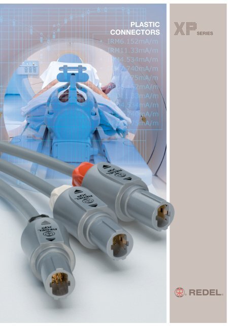
PLASTIC<br />
CONNECTORS<br />
® ®
Precision modular connectors to suit your application<br />
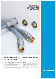
Since its creation in Switzerland in 1946 the LEMO Group has be<strong>en</strong> recognized as a global leader of circular Push-Pull<br />
connectors and connector solutions. Today LEMO and its affiliated companies, <strong>REDEL</strong> and COELVER, are active in more than<br />
80 countries with the help of over 40 subsidiaries and distributors.<br />
Over 5’000 <strong>REDEL</strong> connectors<br />
The modular design of the <strong>REDEL</strong> range provides over 5’000 connectors from ø 14 mm to ø 21 mm, capable of handling cable<br />
diameters up to 9.5 mm and up to 32 contacts.<br />
This vast portfolio <strong>en</strong>ables you to select the ideal connector configuration to suit almost any specific requirem<strong>en</strong>t in most<br />
markets, including medical devices, test and measurem<strong>en</strong>t instrum<strong>en</strong>ts, machinery, audio video broadcast, telecommunications<br />
and military.<br />
<strong>REDEL</strong>’s Push-Pull Self-Latching Connection System<br />
This self-latching system is r<strong>en</strong>owned worldwide for its easy and quick mating and unmating features. It provides absolute<br />
security against vibration, shock or pull on the cable, and facilitates operation in a very limited space.<br />
UL Recognition<br />
®<br />
F v 7 N<br />
F a 110 N<br />
F d 9 N<br />
The <strong>REDEL</strong> self-latching system allows the<br />
connector to be mated by simply pushing<br />
the plug axially into the socket.<br />
F v : average latching force (without contact)<br />
Once firmly latched, connection cannot be<br />
brok<strong>en</strong> by pulling on the cable or any other<br />
compon<strong>en</strong>t part other than the outer release<br />
sleeve.<br />
F a : average ret<strong>en</strong>tion force (without contact)<br />
Wh<strong>en</strong> required, the connector is dis<strong>en</strong>gaged<br />
by a single axial pull on the outer release<br />
sleeve. This first dis<strong>en</strong>gages the latches and<br />
th<strong>en</strong> withdraws the plug from the socket.<br />
F d : average unmating force (without contact)<br />
<strong>REDEL</strong> connectors are recognized by the Underwriters Laboratories (UL). The approval of the complete system (<strong>REDEL</strong><br />
connector, cable and your equipm<strong>en</strong>t) will be easier because <strong>REDEL</strong> connectors are approved.<br />
CE Marking<br />
CE marking means that the appliance or equipm<strong>en</strong>t bearing it complies with the protection requirem<strong>en</strong>ts of one or<br />
several European safety directives.<br />
CE marking applies to complete products or equipm<strong>en</strong>t, but not to electromechanical compon<strong>en</strong>ts, such as<br />
connectors.<br />
RoHS<br />
<strong>REDEL</strong> connector specifications exceed the requirem<strong>en</strong>ts of the RoHS directives (2002/95/EC) of the European Parliam<strong>en</strong>t<br />
and the latest am<strong>en</strong>dm<strong>en</strong>ts. This directive specifies the restrictions of the use of hazardous substances in electrical and electronic<br />
equipm<strong>en</strong>t marketed in Europe. LEMO guarantees that its connectors are free of mercury, cadmium, lead, hexaval<strong>en</strong>t chromium<br />
and polybromide biph<strong>en</strong>yl (PBB), polybromide diph<strong>en</strong>yl ether (PBDE), or DecaBDE.<br />
Cover picture: PET-IRM scanner installed in Hôpitaux Universitaires de G<strong>en</strong>ève (Switzerland).<br />
www.lemo.com
Exploded view of the <strong>REDEL</strong> <strong>XP</strong><br />
Straight plug<br />
backnut cable collet insulator + contacts shell<br />
Straight plug with b<strong>en</strong>d relief<br />
backnut for<br />
b<strong>en</strong>d relief<br />
a b<strong>en</strong>d relief<br />
cable collet insulator + contacts shell<br />
Fixed socket<br />
Free socket<br />
collet nut notched nut insulator + contacts shell<br />
front nut<br />
backnut cable collet insulator + contacts shell<br />
www.lemo.com 1
Standard models<br />
Straight plugs<br />
XA●<br />
XA●<br />
<strong>XP</strong> <strong>Series</strong><br />
The <strong>REDEL</strong> <strong>XP</strong> connectors are plastic Push-Pull connectors. These circular plastic connectors are especially adapted for<br />
applications such as medical electronics and test & measurem<strong>en</strong>t. The <strong>XP</strong> series offer additional features: the latch sleeve<br />
is recessed into the connector body <strong>en</strong>suring greater shock resistance of the product.<br />
The complete connector can be assembled from spare parts (ev<strong>en</strong> the contact configuration) therefore offering good<br />
flexibility in stock keeping. The outer shell in Proprietary sulfone <strong>en</strong>ables ext<strong>en</strong>sive sterilisation cycles of the product. A large<br />
choice of b<strong>en</strong>d relief is available in differ<strong>en</strong>t colour and size. <strong>REDEL</strong> <strong>XP</strong> series connectors are not compatible with the <strong>REDEL</strong><br />
1P or 2P series.<br />
Features & B<strong>en</strong>efits Applications<br />
–Plastic shell made of Proprietary sulfone – Medical electronics<br />
– Blind mating, scoop proof – Test & measurem<strong>en</strong>t<br />
– Ext<strong>en</strong>ded resistance to sterilisation – Industrial electronics<br />
– Enhanced ergonomics «hand grip»<br />
–Increased resistance to shock<br />
– New pat<strong>en</strong>ted Push-Pull system<br />
– UL recognized (file E119802)<br />
Fixed sockets<br />
XL●<br />
XK●<br />
XK●<br />
Free sockets<br />
2 www.lemo.com<br />
XR●<br />
XR●
Part numbering system<br />
www.lemo.com<br />
Model: (pages 4-5)<br />
Keying: (page 6)<br />
Contact configuration (page 6)<br />
Number of contacts: (page 6)<br />
Outershell colour:<br />
Insulator: L = PEEK<br />
Model: (pages 4-5)<br />
Keying: (page 6)<br />
G = grey<br />
N = black<br />
B = white<br />
Plug<br />
Free socket<br />
Contact configuration (page 6)<br />
Number of contacts: (page 6)<br />
Outershell colour:<br />
Insulator: L = PEEK<br />
Model: (pages 4-5)<br />
Keying: (page 6)<br />
G = grey<br />
N = black<br />
B = white<br />
Fixed socket<br />
Contact configuration (page 6)<br />
Number of contacts: (page 6)<br />
Outershell colour:<br />
G = grey<br />
N = black<br />
B = white<br />
. . .<br />
X A N M 1 3 G L A 6 G<br />
. . .<br />
X R N M 1 3 G L L 6 G<br />
Variant<br />
Z = cable collet and nut<br />
for fitting a b<strong>en</strong>d relief<br />
Collet nut colour table: (page 7)<br />
G = grey N = black<br />
A = blue R = red<br />
J = yellow V = gre<strong>en</strong><br />
B = white<br />
Collet: 3 = (cable ø 2.5 mm - 3.9 mm)<br />
5 = (cable ø 4.0 mm - 5.2 mm)<br />
6 = (cable ø 5.3 mm - 6.5 mm)<br />
7 = (cable ø 6.6 mm - 7.5 mm)<br />
Contact type: (page 7)<br />
A = male to solder L = female to solder 1)<br />
C = male to crimp M = female to crimp 1)<br />
Variant<br />
Z = cable collet and nut<br />
for fitting a b<strong>en</strong>d relief<br />
Collet nut colour table: (page 7)<br />
G = grey N = black<br />
A = blue R = red<br />
J = yellow V = gre<strong>en</strong><br />
B = white<br />
Collet: 3 = (cable ø 2.5 mm - 3.9 mm)<br />
5 = (cable ø 4.0 mm - 5.2 mm)<br />
6 = (cable ø 5.3 mm - 6.5 mm)<br />
7 = (cable ø 6.6 mm - 7.5 mm)<br />
Contact type: (page 7)<br />
A = male to solder 1) L = female to solder<br />
C = male to crimp 1) M = female to crimp<br />
Front nut colour table: (page 7)<br />
G = grey N = black<br />
A = blue R = red<br />
J = yellow V = gre<strong>en</strong><br />
B = white<br />
Contact type: (page 7)<br />
A = male to solder 1) C = male to crimp 1)<br />
D = male to print 1) L = female to solder<br />
M= female to crimp N = female to print<br />
V = female 90° for print<br />
Insulator: L = PEEK<br />
XAN.M13.GLA.6G Straight plug with cable collet and alignm<strong>en</strong>t key (N), multipole type with 13 male contacts to solder, grey<br />
Proprietary sulfone shell, PEEK insulator, collet for max cable ø 6.5 mm and grey collet nut.<br />
XRN.M13.GLL.6G Free socket with cable collet and alignm<strong>en</strong>t key (N), multipole type with 13 female contacts to solder, grey<br />
Proprietary sulfone shell, PEEK insulator, collet for max cable ø 6.5 mm and grey collet nut.<br />
XKN.M13.GLLG Fixed socket with two nuts and alignm<strong>en</strong>t key (N), multipole type with 13 female contacts to solder, grey<br />
Proprietary sulfone shell, PEEK insulator and grey plastic front nut.<br />
Note: 1) contacts delivered only with S or T keying (inverted contacts).<br />
X K N . M 1 3 . G L L G<br />
X . M . .<br />
3
Standard models (IP50)<br />
Fixed socket Straight plug<br />
1 Outershell<br />
6 4 2 3 1 5<br />
5 4 2 1 6 3<br />
1 Outershell<br />
2 Insulator<br />
3 Female contact<br />
4 Notched nut<br />
5 Front nut<br />
6 Collet nut<br />
Characteristics<br />
Average ret<strong>en</strong>tion force wh<strong>en</strong><br />
pulling on the cable 1N = 0.102 kg<br />
Cable ret<strong>en</strong>tion force (dep<strong>en</strong>ds on<br />
cable construction) 1N = 0.102 kg<br />
Value Standards<br />
110 IEC 60512-8 test 15f<br />
~130 IEC 60512-9 test 17c<br />
XAN Straight plug, key (N) or keys (P, S and T), with cable collet<br />
ø 16.5<br />
ø 16.5<br />
XLN Fixed socket, key (N) or keys (P, S and T), nut fixing<br />
~46<br />
~48.0<br />
M14 x 1<br />
a<br />
23.5<br />
5.2<br />
ø 18.5<br />
S12.5 7.5 maxi<br />
Characteristics<br />
Endurance (latching)<br />
Working temperature range<br />
(Proprietary sulfone)<br />
Part Number<br />
XAN.M .GLA.3G<br />
XAN.M .GLA.5G<br />
XAN.M .GLA.6G<br />
XAN.M .GLA.7G<br />
min max<br />
2.5 3.9<br />
4.0 5.2<br />
5.3 6.5<br />
6.6 7.5<br />
2 latch sleeve<br />
3 Backnut<br />
4 Insulator<br />
5 Contact<br />
6 Cable collet<br />
Value Standards<br />
> 1000 cycles IEC 60512-5 test 9a<br />
-50/+170°C –<br />
4 www.lemo.com<br />
Cable ø<br />
Note: replace . by contact configuration (see page 6).<br />
XAN Straight plug, key (N) or keys (P, S and T), with cable collet and nut for fitting a b<strong>en</strong>d relief<br />
Part Number<br />
XAN.M .GLA.3GZ<br />
XAN.M .GLA.5GZ<br />
XAN.M .GLA.6GZ<br />
XAN.M .GLA.7GZ<br />
Cable ø<br />
min max<br />
2.5 3.9<br />
4.0 5.2<br />
5.3 6.5<br />
6.6 7.5<br />
Note: replace . by contact configuration (see page 6).<br />
The b<strong>en</strong>d relief must be ordered separately (see page 10).<br />
Part Number<br />
Contact<br />
Solder Crimp<br />
a max (mm) a (mm)<br />
XLN.M .GLLG 2.2 0<br />
Note: all dim<strong>en</strong>sions are in millimeters.<br />
X . M . .<br />
Note: replace . by contact configuration (see page 6).
X . M . .<br />
XKN Fixed socket, key (N) or keys (P, S and T) with two nuts (back panel mounting)<br />
www.lemo.com<br />
ø 15.7<br />
~44.7<br />
M14 x 1<br />
a<br />
S12.5<br />
23.5<br />
3<br />
4<br />
ø 18.5<br />
8.5 maxi<br />
XRN Free socket, key (N) or keys (P, S and T), with cable collet<br />
ø 15.7<br />
~46.7<br />
Part Number<br />
Part Number<br />
XRN.M .GLL.3G<br />
XRN.M .GLL.5G<br />
XRN.M .GLL.6G<br />
XRN.M .GLL.7G<br />
Cable ø<br />
min max<br />
2.5 3.9<br />
4.0 5.2<br />
5.3 6.5<br />
6.6 7.5<br />
Note: replace . by contact configuration (see page 6).<br />
XRN Free socket, key (N) or keys (P, S and T), with cable collet and nut for fitting a b<strong>en</strong>d relief<br />
Part Number<br />
XRN.M .GLL.3GZ<br />
XRN.M .GLL.5GZ<br />
XRN.M .GLL.6GZ<br />
XRN.M .GLL.7GZ<br />
Contact<br />
Solder Crimp<br />
a max (mm) a (mm)<br />
XKN.M .GLLG 2.2 0<br />
Note: replace . by contact configuration (see page 6).<br />
XKN Fixed socket, key (N) or keys (P, S and T) with two nuts (back panel mounting) and with straight print contact<br />
M14 x 1<br />
a<br />
S12.5<br />
23.5<br />
3<br />
4<br />
ø 18.5<br />
8.5 maxi<br />
Part Number<br />
Contact<br />
Solder Crimp<br />
a max (mm) a (mm)<br />
XKN.M .GLNG 4.1 0<br />
Note: replace . by contact configuration (see page 6).<br />
Cable ø<br />
min max<br />
2.5 3.9<br />
4.0 5.2<br />
5.3 6.5<br />
6.6 7.5<br />
Note: replace . by contact configuration (see page 6).<br />
The b<strong>en</strong>d relief must be ordered separately (see page 10).<br />
Note: all dim<strong>en</strong>sions are in millimeters.<br />
5
Multipole<br />
Alignm<strong>en</strong>t key<br />
Verify the third digit of the part number in order to select the right keying. The standard keying is «N» coded.<br />
Keying (plug front view)<br />
Refer<strong>en</strong>ce<br />
Contact type for plug<br />
Contact type for socket<br />
Male solder contacts<br />
ø A<br />
ø A<br />
Male crimp contacts<br />
1<br />
3<br />
6<br />
4<br />
0<br />
30° 60°<br />
N P<br />
male male<br />
female female<br />
Female solder contacts<br />
0<br />
Female crimp contacts<br />
6<br />
4<br />
1<br />
3<br />
Refer<strong>en</strong>ce<br />
0<br />
Insert configuration X . M . .<br />
M04<br />
M06<br />
M08<br />
M10<br />
M13<br />
M16<br />
M18<br />
M22<br />
50° 90°<br />
S T<br />
female female<br />
male male<br />
Number of contacts<br />
4 1.3 1.10 1.40 • • 1.60 0.95 11.5 1.80 1.35 11.5<br />
6 0.9 0.80 1.10 • • 1.50 1.20 8.5 1.90 1.50 8.5<br />
8 0.9 0.80 1.10 • • 1.50 0.75 5.0 1.50 1.1 5.0<br />
10 0.7 0.80 0.80 • • 1.16 0.70 4.2 1.53 1.1 4.2<br />
13 0.7 0.80 0.80 • • 1.05 0.50 4.0 1.30 0.9 4.0<br />
28<br />
16 0.5 0.45 0.45 30<br />
32<br />
• – 0.75 0.47 3.0 1.35 0.8 3.0<br />
28<br />
18 0.5 0.45 0.45 30<br />
32<br />
• – 0.74 0.47 2.5 1.16 0.8 2.5<br />
28<br />
22 0.5 0.45 0.45 30<br />
32<br />
• – 0.60 0.48 2.0 1.30 0.8 2.0<br />
6 www.lemo.com<br />
Contact ø A (mm)<br />
Solder bucket ø (mm) 4)<br />
Crimp bucket ø (mm) 4)<br />
AWG max-min<br />
Contact<br />
type<br />
Solder / Crimp / Print (straight)<br />
Print (elbow)<br />
Test voltage (kV rms) 1)<br />
Contact-contact<br />
Solder Crimp<br />
Note: 1) dep<strong>en</strong>ding on specific application and related standard, more restrictive operating voltage may apply. We suggest operating voltage = 1/3 test voltage, see page 15.<br />
2) shortest distance in air betwe<strong>en</strong> two conductive parts.<br />
3) shortest distance along the surface of the insulating material betwe<strong>en</strong> two conductive parts.<br />
4) for a giv<strong>en</strong> AWG, the diameter of some stranded conductor design is larger than the solder cup diameter (see page 14).<br />
0<br />
18 4)<br />
20<br />
22<br />
20<br />
22<br />
24<br />
20<br />
22<br />
24<br />
22 4)<br />
24<br />
26<br />
22 4)<br />
24<br />
26<br />
X . M<br />
. .<br />
Air clearance min 2) (mm)<br />
Creepage distance min 3) (mm)<br />
Rated curr<strong>en</strong>t (A)<br />
Test voltage (kV rms) 1)<br />
Contact-contact<br />
Air clearance min 2) (mm)<br />
Creepage distance min 3) (mm)<br />
Rated curr<strong>en</strong>t (A)
Plug<br />
Outer shell material<br />
Material<br />
Proprietary<br />
sulfone<br />
Refer<strong>en</strong>ce<br />
RAL code<br />
www.lemo.com<br />
Ref.<br />
Colour Temperature<br />
G Grey<br />
N Black<br />
B White<br />
Contact type<br />
Type<br />
solder<br />
crimp<br />
Male Female<br />
A L1) C M1) Socket Male Female<br />
Type<br />
solder<br />
crimp<br />
print<br />
print 90°<br />
A 1) L<br />
- M<br />
D 1) N<br />
- V<br />
Note: 1) only for S or T keying.<br />
Colour coding<br />
-50° / +170°C<br />
Select the type of contact: solder or crimp?<br />
Colours<br />
grey blue yellow black red gre<strong>en</strong> white<br />
G A J N R V B<br />
7001 5015 1016 9005 3020 6019 9003<br />
Note: adapted for sterilisation satured steam (120°C or 134°C).<br />
Wh<strong>en</strong> should I use crimp rather than solder contacts ?<br />
Soldering<br />
recomm<strong>en</strong>ded for small volumes<br />
requires little amount of tooling (soldering iron)<br />
requires more time<br />
Crimping<br />
recomm<strong>en</strong>ded for large volumes<br />
no heat is required to make the connection<br />
for contacts with high d<strong>en</strong>sity<br />
for use in high temperature <strong>en</strong>vironm<strong>en</strong>t (max. 170°C)<br />
requires extra tooling (crimping tools)<br />
Note: the RAL colours are indicative and dep<strong>en</strong>d on raw material and production process.<br />
Colour may differ.<br />
Easy id<strong>en</strong>tification with the assistance of colour coding. Outershell is only available in grey, black or white.<br />
X . M . .<br />
X . M . .<br />
X . M . .<br />
7
Accessories<br />
XAN / XLN Insulator and male or female crimp contacts<br />
male / black marking<br />
female / black marking<br />
XAN / XLN Insulator with male or female solder contacts<br />
male / black marking female / black marking<br />
XAl.100.lZZ Plug outershell kit (no contacts)<br />
XRl.200.ll Free socket outershell kit (no contacts)<br />
XLl.200.lZZl Socket outershell kit (nut fixing), (no contacts)<br />
~36<br />
23.5<br />
~35<br />
ø 18.5<br />
Contact nb. of ø contact<br />
configuration contacts (mm)<br />
M04 4 1.3<br />
M06 6 0.9<br />
M08 8 0.9<br />
M10 10 0.7<br />
M13 13 0.7<br />
M16 16 0.5<br />
M18 18 0.5<br />
M22 22 0.5<br />
Contact nb. of ø contact<br />
configuration contacts (mm)<br />
M04 4 1.3<br />
M06 6 0.9<br />
M08 8 0.9<br />
M10 10 0.7<br />
M13 13 0.7<br />
M16 16 0.5<br />
M18 18 0.5<br />
M22 22 0.5<br />
Part Number<br />
XA .100.GZZ<br />
XA .100.BZZ<br />
XA .100.NZZ<br />
Part Number<br />
XR .200.RG<br />
XR .200.RB<br />
XR .200.RN<br />
8 www.lemo.com<br />
Colours<br />
grey<br />
white<br />
black<br />
Note: replace by alignm<strong>en</strong>t key (N, P, S or T).<br />
Part Number<br />
XL .200.GZZG<br />
XL .200.BZZB<br />
XL .200.NZZN<br />
Colours<br />
grey<br />
white<br />
black<br />
Note: replace by alignm<strong>en</strong>t key (N, P, S or T).<br />
Colours<br />
grey<br />
white<br />
black<br />
Note: replace by alignm<strong>en</strong>t key (N, P, S or T).<br />
Kit contact part<br />
number<br />
Male<br />
XAN.M04.ZLC<br />
XAN.M06.ZLC<br />
XAN.M08.ZLC<br />
XAN.M10.ZLC<br />
XAN.M13.ZLC<br />
XAN.M16.ZLC<br />
XAN.M18.ZLC<br />
XAN.M22.ZLC<br />
Kit contact part<br />
number<br />
Male<br />
XAN.M04.ZLA<br />
XAN.M06.ZLA<br />
XAN.M08.ZLA<br />
XAN.M10.ZLA<br />
XAN.M13.ZLA<br />
XAN.M16.ZLA<br />
XAN.M18.ZLA<br />
XAN.M22.ZLA<br />
Kit contact part<br />
number<br />
Female<br />
XLN.M04.ZLM<br />
XLN.M06.ZLM<br />
XLN.M08.ZLM<br />
XLN.M10.ZLM<br />
XLN.M13.ZLM<br />
XLN.M16.ZLM<br />
XLN.M18.ZLM<br />
XLN.M22.ZLM<br />
Kit contact part<br />
number<br />
Female<br />
XLN.M04.ZLL<br />
XLN.M06.ZLL<br />
XLN.M08.ZLL<br />
XLN.M10.ZLL<br />
XLN.M13.ZLL<br />
XLN.M16.ZLL<br />
XLN.M18.ZLL<br />
XLN.M22.ZLL
XKl.200.lZZl Socket outershell kit (with two nuts), (no contacts)<br />
XAN Collet<br />
max ø 9.8<br />
21.5<br />
XAM.130.ll Nut for fitting a GMA.1B b<strong>en</strong>d relief<br />
XLN Notched nut<br />
XLN Collet nut<br />
ø 10<br />
18.5<br />
23.5<br />
20.3<br />
ø 18.5<br />
M14 x 1 4<br />
M11 x 0.75<br />
12.5<br />
XLN Plastic front nut for XLl models<br />
18.5<br />
M14 x 1<br />
4.5<br />
5.2<br />
ø 12.5<br />
Part Number<br />
XK .200.GZZG<br />
XK .200.BZZB<br />
XK .200.NZZN<br />
Part Number<br />
XAN.739.RG<br />
XAN.752.RG<br />
XAN.765.RG<br />
XAN.775.RG<br />
Part Number<br />
XAM.130.RG<br />
XAM.130.RB<br />
XAM.130.RN<br />
Cable ø (mm)<br />
min. max.<br />
2.5 3.9<br />
4.0 5.2<br />
5.3 6.5<br />
6.6 7.5<br />
Note: all dim<strong>en</strong>sions are in millimeters.<br />
www.lemo.com 9<br />
Colours<br />
grey<br />
white<br />
black<br />
Note: replace by alignm<strong>en</strong>t key (N, P, S or T).<br />
Colours<br />
grey<br />
white<br />
black<br />
Note: only for XA , XR models.<br />
Part Number<br />
XLN.240.RG<br />
Part Number<br />
XLN.230.RG<br />
Part Number<br />
XLN.220.RG<br />
XLN.220.RB<br />
XLN.220.RR<br />
XLN.220.RN<br />
XLN.220.RJ<br />
XLN.220.RA<br />
XLN.220.RV<br />
Colours<br />
grey<br />
Colours<br />
grey<br />
Colours<br />
grey<br />
white<br />
red<br />
black<br />
yellow<br />
blue<br />
gre<strong>en</strong>
XKN Plastic front nut for XKl models<br />
GMA.1B B<strong>en</strong>d relief<br />
Part Number<br />
GMA.1B.025.DG<br />
GMA.1B.030.DG<br />
GMA.1B.035.DG<br />
GMA.1B.040.DG<br />
GMA.1B.045.DG<br />
GMA.1B.054.DG<br />
GMA.1B.065.DG<br />
GMA.1B.025.RG<br />
GMA.1B.030.RG<br />
GMA.1B.035.RG<br />
GMA.1B.040.RG<br />
GMA.1B.045.RG<br />
GMA.1B.051.RG<br />
GMA.1B.057.RG<br />
GMA.1B.063.RG<br />
Dim<strong>en</strong>sions (mm)<br />
B<strong>en</strong>d relief Cable ø<br />
A L max. min.<br />
2.5 30 2.9 2.5<br />
3.0 30 3.4 3.0<br />
3.5 30 3.9 3.5<br />
4.0 30 4.4 4.0<br />
4.5 30 4.9 4.5<br />
5.4 30 6.0 5.4<br />
6.5 30 7.0 6.5<br />
2.5 34 2.9 2.5<br />
3.0 34 3.4 3.0<br />
3.5 34 3.9 3.5<br />
4.0 34 4.4 4.0<br />
4.5 34 5.0 4.5<br />
5.1 34 5.6 5.1<br />
5.7 34 6.2 5.7<br />
6.3 34 7.0 6.3<br />
18.5<br />
M14 x 1<br />
L<br />
Material<br />
Desmopan<br />
786<br />
Polyurethane<br />
elastomer<br />
Silicone<br />
elastomer<br />
VMQ<br />
4<br />
ø A<br />
Temperature range<br />
in dry atmosphere in water steam<br />
-40°C, +80°C –<br />
Part Number<br />
XKN.220.RG<br />
XKN.220.RB<br />
XKN.220.RR<br />
XKN.220.RN<br />
XKN.220.RJ<br />
XKN.220.RA<br />
XKN.220.RV<br />
-60°C, +200°C +140°C<br />
A b<strong>en</strong>d relief absorbs the angular force that may be exerted on<br />
cables.<br />
These are designed for plugs and free sockets with cable collet<br />
and nut.<br />
The Colours of these b<strong>en</strong>d reliefs are not id<strong>en</strong>tical to the RAL<br />
coulours of the socket’s front nut.<br />
Refer<strong>en</strong>ce<br />
Note: the last letter «G» of the part number indicates a grey colour, see the adjac<strong>en</strong>t table and replace letter «G» by the letter of the colour required.<br />
All dim<strong>en</strong>sions are in millimeters.<br />
Note: the selection of pigm<strong>en</strong>ts, which should<br />
remain stable at high temperature, is limited<br />
by the new regulations. For this reason, some<br />
colours will be a shade differ<strong>en</strong>t from those<br />
used for Desmopan b<strong>en</strong>d reliefs.<br />
The selected solutions repres<strong>en</strong>t the best possible<br />
compromise.<br />
10 www.lemo.com<br />
Colours<br />
grey<br />
white<br />
red<br />
black<br />
yellow<br />
blue<br />
gre<strong>en</strong><br />
A<br />
B<br />
G<br />
J<br />
M<br />
N<br />
R<br />
S<br />
V<br />
Colours<br />
blue<br />
white<br />
grey<br />
yellow<br />
brown<br />
black<br />
red<br />
orange<br />
gre<strong>en</strong>
Tooling<br />
XOP.019.HN Spanners with notch for securing<br />
the notched nut<br />
Material: Black polyamide. For notched nut XLN.240.RG.<br />
DPC.91.701.V Crimping tool XOE Positioners for crimp contacts<br />
DCF Automatic extraction tools for crimp contacts<br />
Configuration<br />
www.lemo.com<br />
Contact ø Conductor<br />
(mm) AWG<br />
M04 1.3 18-20<br />
M06/M08 0.9 20-22-24<br />
M10/M13 0.7 22-24-26<br />
M16/M18/M22 0.5 28-30-32<br />
Positioner part number<br />
Male contact Female contact<br />
XOE.130.VC XOE.130.VM<br />
XOE.090.VC XOE.090.VM<br />
XOE.070.VC XOE.070.VM<br />
XOE.050.VC XOE.050.VM<br />
male female<br />
Selector No<br />
Setting<br />
6-5-5<br />
6-5-5<br />
6-5-5<br />
4-3-3<br />
Part number extractor<br />
Male contact Female contact<br />
DCF.93.131.4LT DCF.93.131.4LT<br />
DCF.93.090.4LT DCF.93.090.4LT<br />
DCF.93.070.4LT DCF.93.070.4LT<br />
DCF.91.050.2LT 1) DCF.91.050.2LT 1)<br />
Note: the variance in conductor stranding diameter for the minimum AWG is such that some can have a cross section which is not suffici<strong>en</strong>t to guarantee crimping as per<br />
IEC 60352-2 standard.<br />
1) With this extractor, the user must remove the insulator from the outer shell.<br />
All dim<strong>en</strong>sions are in millimeters.<br />
76.7<br />
28<br />
XOB.186.GN Spanners for nut XLN.220Rl<br />
XOB.187.GN Spanners for nut XKN.220Rl<br />
Material: Black polyamide<br />
30 ø 20<br />
11
Panel hole<br />
For XLl and XKl<br />
12.6 ± 0.05<br />
23.5 min.<br />
PCB drilling pattern<br />
For straight contacts<br />
4 x ø 0.8 0.1 +<br />
0<br />
1.78<br />
1.74<br />
1.78<br />
2.3<br />
2.3<br />
13 x ø 0.8 0.1 +<br />
0<br />
0.87<br />
0.8<br />
0.8<br />
1.1 1.1<br />
M04<br />
1.6<br />
1.6<br />
1.65 1.65<br />
M13<br />
Note: all dim<strong>en</strong>sions are in millimeters<br />
+ 0.1<br />
0<br />
ø 14.0<br />
6 x ø 0.8 0.1 +<br />
0<br />
1.3<br />
1.3<br />
16 x ø 0.6 0.1 +<br />
0<br />
2.4<br />
2.4<br />
0.65<br />
1.2 1.2<br />
M06<br />
1.3<br />
1.3<br />
1.4 1.4<br />
M16<br />
Note: Socket mounting nut torque = 1 Nm.<br />
All dim<strong>en</strong>sions are in millimeters.<br />
8 x ø 0.8 0.1 +<br />
0<br />
12 www.lemo.com<br />
1.6<br />
1.6<br />
18 x ø 0.6 0.1 +<br />
0<br />
2.65<br />
2.65<br />
0.8<br />
1.35<br />
1.35<br />
1.5 1.5<br />
M08<br />
1.6<br />
1.6<br />
1.7 1.7<br />
M18<br />
0.65 0.65<br />
2.1 2.1<br />
10 x ø 0.8 0.1 +<br />
0<br />
1.32<br />
1.32<br />
22 x ø 0.6 0.1 +<br />
0<br />
1.1<br />
1.1<br />
0.66<br />
0.66<br />
1.5 1.5<br />
M10<br />
1.32<br />
1.32<br />
1.81 1.81<br />
0.67 0.67<br />
M22<br />
2.1 2.1<br />
1.97<br />
1.97
Assembly instructions<br />
Solder contacts / Crimp contacts<br />
www.lemo.com<br />
L<br />
➀ ➁ ➂ ➄ ➅ ➆<br />
T<br />
solder / crimp<br />
1. Slide the collet nut ➀ and th<strong>en</strong> the collet ➁ onto the cable.<br />
Configuration<br />
M04<br />
M06, M08<br />
M10, M13<br />
M16 to M22<br />
Dim<strong>en</strong>sions (mm)<br />
Solder contacts Crimp contacts<br />
L T L T<br />
11.5 3.5 15.0 3.5<br />
13.0 3.0 15.0 3.5<br />
13.0 3.0 15.0 3.5<br />
12.5 2.5 14.5 2.5<br />
2. Strip the cable according to the l<strong>en</strong>gths giv<strong>en</strong> in the table.<br />
Tin the conductors.<br />
3. Solder conductors into contacts, starting with the c<strong>en</strong>ter<br />
contacts, making sure that neither solder nor flux gets onto<br />
the insulator or cable insulation.<br />
Fix the appropriate positioner in the crimping tool. Set<br />
selector to the number corresponding to the conductor<br />
AWG as indicated on the positioner label. Fit conductor<br />
into contact and make sure it is visible through the inspection<br />
hole in the crimp barrel. Slide conductor-contact combination<br />
into the op<strong>en</strong> crimping tool; make sure that the<br />
contact is fully pushed into the positioner. Close the tool.<br />
Remove from crimping tool and check that conductor is<br />
secure in contact and shows in inspection hole.<br />
4. Slide the collet ➁ forward and locate both tags ➂ in the<br />
slots ➄ on the insulator ➅.<br />
Push collet ➁ and insulator ➅ assembly into the shell ➆<br />
whilst turning it to <strong>en</strong>sure that the tag ➂ locates in the<br />
inside slot of the shell.<br />
5. Slide collet nut ➀ over collet ➁ and tight<strong>en</strong> the collet nut ➀<br />
to the maximum torque of 0.3 Nm.<br />
– Socket mounting nut torque = 1 Nm.<br />
13
Table of American Wire Gauge<br />
AWG<br />
0<br />
1<br />
2<br />
4<br />
6<br />
8<br />
8<br />
10<br />
10<br />
10<br />
12<br />
12<br />
12 1)<br />
12<br />
14<br />
14<br />
14 1)<br />
14<br />
16 1)<br />
16<br />
16<br />
16 1)<br />
16<br />
18 1)<br />
18 1)<br />
18<br />
18<br />
18<br />
18<br />
20 1)<br />
20<br />
20<br />
20<br />
20<br />
22<br />
22<br />
22<br />
24 1)<br />
24<br />
24<br />
24<br />
26<br />
26<br />
26<br />
28 1)<br />
28<br />
28<br />
30<br />
30<br />
32<br />
32<br />
34<br />
36<br />
38<br />
40<br />
Technical tables<br />
Construction ø wire max Wire section<br />
(mm) (in) (mm2) Strand<br />
nb<br />
AWG/<br />
strand<br />
(sq in)<br />
259 24 11.277 0.444 52.90 0.0820<br />
817 30 9.702 0.382 41.40 0.0641<br />
259 26 8.89 0.35 33.20 0.0514<br />
133 25 6.9596 0.274 21.5925 0.0335<br />
133 27 5.5118 0.217 13.5885 0.0211<br />
168 30 4.4450 0.175 8.5127 0.0132<br />
133 29 4.3942 0.173 8.6053 0.0133<br />
105 30 3.3020 0.13 5.3204 0.0082<br />
37 26 2.9210 0.115 4.7397 0.0073<br />
1 10 2.6162 0.103 5.2614 0.0082<br />
37 28 2.3114 0.091 2.9765 0.0046<br />
19 25 2.3622 0.093 3.0847 0.0048<br />
7 20 2.5400 0.10 3.6321 0.0056<br />
1 12 2.0828 0.082 3.3081 0.0051<br />
41 30 2.0574 0.081 2.0775 0.0032<br />
19 27 1.8542 0.073 1.9413 0.0030<br />
7 22 2.0828 0.082 2.2704 0.0035<br />
1 14 1.6510 0.065 2.0820 0.0032<br />
65 34 1.5748 0.062 1.3072 0.0020<br />
26 30 1.5748 0.062 1.3174 0.0020<br />
19 29 1.4986 0.059 1.2293 0.0019<br />
7 24 1.5494 0.061 1.4330 0.0022<br />
1 16 1.3208 0.052 1.3076 0.0020<br />
65 36 1.2700 0.05 0.8234 0.0013<br />
42 34 1.2700 0.05 0.8447 0.0013<br />
19 30 1.3208 0.052 0.9627 0.0015<br />
16 30 1.2954 0.051 0.8107 0.0013<br />
7 26 1.2700 0.05 0.8967 0.0014<br />
1 18 1.0414 0.041 0.8229 0.0013<br />
42 36 1.0160 0.04 0.5320 8.2x10 -4<br />
19 32 1.0414 0.041 0.6162 0.0010<br />
10 30 1.0160 0.04 0.5067 7.9x10 -4<br />
7 28 0.9906 0.039 0.5631 8.7x10 -4<br />
1 20 0.8382 0.033 0.5189 8.0x10 -4<br />
19 34 0.8382 0.033 0.3821 5.9x10 -4<br />
7 30 0.7874 0.031 0.3547 5.5x10 -4<br />
1 22 0.6604 0.026 0.3243 5.0x10 -4<br />
42 40 0.6604 0.026 0.2045 3.2x10 -4<br />
19 36 0.6858 0.027 0.2407 3.7x10 -4<br />
7 32 0.6350 0.025 0.2270 3.5x10 -4<br />
1 24 0.5588 0.022 0.2047 3.2x10 -4<br />
19 38 0.5588 0.022 0.1540 2.4x10 -4<br />
7 34 0.5080 0.02 0.1408 2.2x10 -4<br />
1 26 0.4318 0.017 0.1281 2.0x10 -4<br />
19 40 0.4318 0.017 0.0925 1.4x10 -4<br />
7 36 0.4064 0.016 0.0887 1.4x10 -4<br />
1 28 0.3302 0.013 0.0804 1.2x10 -4<br />
7 38 0.3302 0.013 0.0568 8.8x10 -5<br />
1 30 0.2794 0.011 0.0507 7.9x10 -5<br />
7 40 0.2794 0.011 0.0341 5.3x10 -5<br />
1 32 0.2286 0.009 0.0324 5.0x10 -5<br />
1 34 0.1693 0.007 0.0201 3.1x10 -5<br />
1 36 0.127 0.005 0.0127 2.0x10 -5<br />
1 38 0.1016 0.004 0.0081 1.3x10 -5<br />
1 40 0.078 0.003 0.0049 7.5x10 -6<br />
Table of wire gauges according to IEC-60228 standard<br />
Conductor no<br />
x ø (mm)<br />
196x0.40<br />
7x2.14<br />
125x0.40<br />
7x1.72<br />
1x4.50<br />
80x0.40<br />
7x1.38<br />
1x3.60<br />
84x0.30<br />
7x1.50<br />
1x2.76<br />
56x0.30<br />
7x0.86<br />
1x2.25<br />
50x0.25<br />
7x0.68<br />
1x1.78<br />
30x0.25<br />
7x0.52<br />
1x1.4<br />
32x0.20<br />
7x0.43<br />
1x1.15<br />
42x0.15<br />
28x0.20<br />
1x1.0<br />
28x0.15<br />
16x0.20<br />
1x0.80<br />
7x0.25<br />
1x0.60<br />
14x0.15<br />
7x0.20<br />
18x0.10<br />
14x0.10<br />
21x0.07<br />
14x0.10<br />
Note: 1) not included in the standard<br />
Max ø Max ø Section Section<br />
(mm) (in) (mm 2) (sq in)<br />
7.50 0.295 25.00 0.0387<br />
6.10 0.240 25.00 0.0387<br />
6.00 0.236 16.00 0.0248<br />
4.90 0.192 16.00 0.0248<br />
4.50 0.177 16.00 0.0248<br />
4.70 0.155 10.00 0.0155<br />
3.95 0.155 10.00 0.0155<br />
3.60 0.141 10.00 0.0155<br />
3.70 0.145 6.00 0.0093<br />
3.15 0.124 6.00 0.0093<br />
2.76 0.108 6.00 0.0093<br />
2.80 0.110 4.00 0.0062<br />
2.58 0.098 4.00 0.0062<br />
2.25 0.082 4.00 0.0062<br />
2.15 0.084 2.50 0.0038<br />
2.04 0.080 2.50 0.0038<br />
1.78 0.070 2.50 0.0038<br />
1.60 0.062 1.50 0.0023<br />
1.56 0.061 1.50 0.0023<br />
1.40 0.055 1.50 0.0023<br />
1.35 0.053 1.00 0.0015<br />
1.29 0.050 1.00 0.0015<br />
1.15 0.045 1.00 0.0015<br />
1.20 0.047 0.75 0.0011<br />
1.15 0.045 0.75 0.0011<br />
1.00 0.039 0.75 0.0011<br />
0.95 0.037 0.50 7.7x10 -4<br />
0.90 0.035 0.50 7.7x10 -4<br />
0.80 0.031 0.50 7.7x10 -4<br />
0.75 0.029 0.34 5.2x10 -4<br />
0.60 0.023 0.28 4.3x10 -4<br />
0.75 0.029 0.25 3.8x10 -4<br />
0.65 0.023 0.22 3.4x10 -4<br />
0.50 0.019 0.14 2.1x10 -4<br />
0.40 0.015 0.11 1.7x10 -4<br />
0.40 0.015 0.09 1.3x10 -4<br />
0.40 0.015 0.09 1.3x10 -4<br />
14 www.lemo.com
Product safety notice<br />
PLEASE READ AND FOLLOW ALL INSTUCTIONS CAREFULLY AND CONSULT ALL RELEVENT NATIONAL AND<br />
INTERNATIONAL SAFETY REGULATIONS FOR YOUR APPLICATION.<br />
IMPROPER HANDLING, CABLE ASSEMBLY, OR WRONG USE OF CONNECTORS CAN RESULT IN HAZARDOUS<br />
SITUATIONS.<br />
1. SHOCK AND FIRE HAZARD<br />
Incorrect wiring, the use of damaged compon<strong>en</strong>ts, pres<strong>en</strong>ce of foreign objects (such as metal debris), and / or residue<br />
(such as cleaning fluids), can result in short circuits, overheating, and / or risk of electric shock.<br />
Mated compon<strong>en</strong>ts should never be disconnected while live as this may result in an exposed electric arc and local<br />
overheating, resulting in possible damage to compon<strong>en</strong>ts.<br />
2. HANDLING<br />
Connectors and their compon<strong>en</strong>ts should be visually inspected for damage prior to installation and assembly. Suspect<br />
compon<strong>en</strong>ts should be rejected or returned to the factory for verification.<br />
Connector assembly and installation should only be carried out by properly trained personnel. Proper tools must be used<br />
during installation and / or assembly in order to obtain safe and reliable performance.<br />
3. USE<br />
Connectors with exposed contacts should never be live (or on the curr<strong>en</strong>t supply side of a circuit). Under g<strong>en</strong>eral<br />
conditions voltages above 30 VAC and 42 VDC are considered hazardous and proper measures should be tak<strong>en</strong> to<br />
eliminate all risk of transmission of such voltages to any exposed metal part of the connector.<br />
4. TEST AND OPERATING VOLTAGES<br />
The maximum admissible operating voltage dep<strong>en</strong>ds upon the national or international standards in force for the<br />
application in question. Air and creepage distances impact the operating voltage; refer<strong>en</strong>ce values are indicated in the<br />
catalog however these may be influ<strong>en</strong>ced by PC board design and / or wiring harnesses.<br />
The test voltage indicated in the catalog is 75% of the mean breakdown voltage; the test is applied at 500 V/s and the<br />
test duration is 1 minute.<br />
5. CE MARKING<br />
CE marking means that the appliance or equipm<strong>en</strong>t bearing it complies with the protection requirem<strong>en</strong>ts of one or<br />
several European safety directives.<br />
CE marking applies to complete products or equipm<strong>en</strong>t, but not to electromechanical compon<strong>en</strong>ts, such as<br />
connectors.<br />
6. PRODUCT IMPROVEMENTS<br />
The LEMO Group reserves the right to modify and improve to our products or specifications without providing prior<br />
notification.<br />
www.lemo.com<br />
15
Notes<br />
16 www.lemo.com
LEMO complete product range<br />
Unipole<br />
Multipole<br />
Coaxial 50 Ω<br />
Coaxial 75 Ω<br />
Multi Coaxial<br />
Mixed Coax + LV<br />
Triaxial 50 Ω<br />
Triaxial 75 Ω<br />
Mixed Triax + LV<br />
Quadrax<br />
High Voltage<br />
Multi High Voltage<br />
Mixed HV + LV<br />
Fibre Optic<br />
Multi Fibre Optic<br />
Mixed FO + LV<br />
Thermocouple<br />
Fluidic<br />
Multi Fluidic<br />
Mixed Fluidic + LV<br />
B S K E F 00 01 0A 3T 4A 4M 3K.<br />
93C<br />
Most frequ<strong>en</strong>tly used in darker colour<br />
No reproduction or use without express permission of editorial or pictorial cont<strong>en</strong>t, in any manner.<br />
LEMO SA reserves the right to modify and improve specifications, at all times, without any notification.<br />
1D Y 05 5G 2G 2C L H M R N 03 V W F P D K/S 01 DIN<br />
B <strong>Series</strong> Keyed S <strong>Series</strong> K <strong>Series</strong> Keyed E <strong>Series</strong> F <strong>Series</strong> Keyed 00 <strong>Series</strong> 01 <strong>Series</strong><br />
0A <strong>Series</strong> 3T <strong>Series</strong> 4A <strong>Series</strong> 4M <strong>Series</strong> Keyed 3K.93C <strong>Series</strong> Keyed 1D <strong>Series</strong> Y <strong>Series</strong><br />
05 <strong>Series</strong> 5G <strong>Series</strong> Keyed 2G <strong>Series</strong> Keyed 2C <strong>Series</strong> L <strong>Series</strong> Keyed H <strong>Series</strong> M <strong>Series</strong> Keyed<br />
R <strong>Series</strong> Keyed N <strong>Series</strong> Keyed 03 <strong>Series</strong> Keyed V <strong>Series</strong> W <strong>Series</strong> Keyed Cable assembly K/S <strong>Series</strong> Keyed<br />
<strong>REDEL</strong> F <strong>Series</strong> P <strong>REDEL</strong> <strong>Series</strong> Keyed D <strong>REDEL</strong> <strong>Series</strong> 01 <strong>Series</strong> Keyed VAA <strong>Series</strong> SAA <strong>Series</strong> TAA <strong>Series</strong>
LEMO HEADQUARTERS<br />
SWITZERLAND<br />
LEMO SA<br />
Chemin des Champs-Courbes 28 - P.O. Box 194 - CH-1024 Ecubl<strong>en</strong>s<br />
Tel. (+41 21) 695 16 00 - Fax (+41 21) 695 16 02 - e-mail: info@lemo.com<br />
LEMO SUBSIDIARIES<br />
AUSTRIA<br />
LEMO Elektronik GesmbH<br />
Lemböckgasse 49/E6-3<br />
1230 Wi<strong>en</strong><br />
Tel: (+43 1) 914 23 20 0<br />
Fax:(+43 1) 914 23 20 11<br />
sales@lemo.at<br />
CHINA<br />
LEMO Trading (Shanghai) Co., Ltd<br />
LEMO Electronics (Shanghai) Co., Ltd<br />
5th Floor, Block 6, City of ELITE,<br />
1000 Jinhai Road, Pudong<br />
Shanghai, China 201206<br />
Tel: (+86 21) 5899 7721<br />
Fax: (+86 21) 5899 7727<br />
cn.sales@lemo.com<br />
DENMARK<br />
LEMO D<strong>en</strong>mark A/S<br />
Gammel Mosevej 46<br />
2820 G<strong>en</strong>tofte<br />
Tel: (+45) 45 20 44 00<br />
Fax: (+45) 45 20 44 01<br />
info-dk@lemo.com<br />
FRANCE<br />
LEMO France Sàrl<br />
24/28 Av<strong>en</strong>ue Graham Bell<br />
Bâtim<strong>en</strong>t Balthus 4<br />
Bussy Saint Georges<br />
77607 Marne la Vallée Cedex 3<br />
Tel: (+33 1) 60 94 60 94<br />
Fax: (+33 1) 60 94 60 90<br />
info-fr@lemo.com<br />
GERMANY<br />
LEMO Elektronik GmbH<br />
Hanns-Schwindt-Str. 6<br />
81829 Münch<strong>en</strong><br />
Tel: (+49 89) 42 77 03<br />
Fax: (+49 89) 420 21 92<br />
info@lemo.de<br />
HONG KONG<br />
LEMO Hong Kong Ltd<br />
Unit 1207, 12/F, Corporation Square,<br />
8 Lam Lok Street, Kowloon Bay,<br />
Kowloon - Hong Kong<br />
Tel: (+852) 2174 0468<br />
Fax: (+852) 2174 0492<br />
hk.sales@lemo.com<br />
HUNGARY<br />
<strong>REDEL</strong> Elektronika Kft<br />
Nagysándor József u. 6-12<br />
1201 Budapest<br />
Tel: (+36 1) 421 47 10<br />
Fax: (+36 1) 421 47 57<br />
redelemo@lemo.hu<br />
ITALY<br />
LEMO Italia srl<br />
Viale Lunigiana 25<br />
20125 Milano<br />
Tel: (+39 02) 66 71 10 46<br />
Fax: (+39 02) 66 71 10 66<br />
sales.it@lemo.com<br />
JAPAN<br />
LEMO Japan Ltd<br />
4-10-3, Takaido Higashi,<br />
Suginami-ku, Tokyo, 168-0072<br />
Tel: (+81 3) 53 44 39 33<br />
Fax: (+81 3) 53 44 39 35<br />
lemoinfo@lemo.co.jp<br />
LEMO DISTRIBUTORS<br />
AUSTRALIA, BRAZIL, CANADA, CZECH REPUBLIC, GREECE, INDIA, ISRAEL,<br />
NEW ZEALAND, PAKISTAN, POLAND, RUSSIA, SOUTH AFRICA, SOUTH KOREA,<br />
TAIWAN, TURKEY, UKRAINE<br />
18<br />
www.lemo.com<br />
NETHERLANDS / BELGIUM<br />
LEMO Connectors B<strong>en</strong>elux<br />
De Trompet 1060<br />
1967 DD Heemskerk<br />
Tel. (+31) 251 25 78 20<br />
Fax (+31) 251 25 78 21<br />
info@lemo.nl<br />
NORWAY / ICELAND<br />
LEMO Norway A/S<br />
Stansevei<strong>en</strong> 6B<br />
0975 Oslo<br />
Tel: (+47) 22 91 70 40<br />
Fax: (+47) 22 91 70 41<br />
info-no@lemo.com<br />
SINGAPORE<br />
LEMO Asia Pte Ltd<br />
4 L<strong>en</strong>g Kee Road,<br />
#06-09 SiS Building<br />
Singapore 159088<br />
Tel: (+65) 6476 0672<br />
Fax: (+65) 6474 0672<br />
sg.sales@lemo.com<br />
SPAIN / PORTUGAL<br />
IBERLEMO S.A.<br />
Brasil, 45, 08402 Granollers<br />
Barcelona<br />
Tel: (+34 93) 860 44 20<br />
Fax: (+34 93) 879 10 77<br />
info-es@lemo.com<br />
Madrid Office<br />
Antonio López, 96, 28019 Madrid<br />
Tel: (+34 91) 469 99 19<br />
Fax: (+34 91) 469 99 59<br />
SWEDEN / FINLAND<br />
LEMO Nordic AB<br />
Mariehällsväg<strong>en</strong> 39A<br />
168 65 Bromma<br />
Tel: (+46 8) 635 60 60<br />
Fax: (+46 8) 635 60 61<br />
info-se@lemo.com<br />
SWITZERLAND<br />
LEMO Verkauf AG<br />
Grundstrasse 22 B<br />
6343 Rotkreuz<br />
Tel: (+41 41) 790 49 40<br />
Fax: (+41 41) 790 49 43<br />
ch.sales@lemo.com<br />
UNITED KINGDOM<br />
LEMO UK Ltd<br />
12-20 North Street<br />
Worthing<br />
West Sussex, BN11 1DU<br />
Tel: (+44 1903) 23 45 43<br />
Fax: (+44 1903) 20 62 31<br />
lemouk@lemo.com<br />
USA<br />
LEMO USA Inc<br />
P.O. Box 2408<br />
Rohnert Park, CA 94927-2408<br />
Tel: (+1 707) 578 88 11<br />
(+1 800) 444 53 66<br />
Fax:(+1 707) 578 08 69<br />
info@lemousa.com<br />
© CAT.<strong>XP</strong>.REN.P1010, updated November, 2011