Shielded Plug with Metal Inner Parts
Shielded Plug with Metal Inner Parts
Shielded Plug with Metal Inner Parts

Create successful ePaper yourself
Turn your PDF publications into a flip-book with our unique Google optimized e-Paper software.
Catalogue No.: 1005PC-b-e<br />
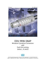
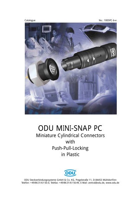
ODU MINI-SNAP PC<br />
Miniature Cylindrical Connectors<br />
<strong>with</strong><br />
Push-Pull-Locking<br />
in Plastic<br />
ODU Steckverbindungssysteme GmbH & Co. KG, Pregelstraße 11, D-84453 Mühldorf/Inn<br />
Telefon: +49/86 31/61 56-0, Telefax: +49/86 31/61 56 49, E-Mail: zentral@odu.de, www.odu.de
The latest version of this catalogue<br />
is posted on our websites:<br />
www.odu.de or www.odu-usa.com<br />
UL-File E110586 01 RT07175<br />
All data and specifications subject<br />
to change <strong>with</strong>out notice.<br />
All dimensions in mm.<br />
All pictures are illustrations.
Table of Contents ODU MINI-SNAP PC<br />
Introduction . . . . . . . . . . . . . . . . . . . . . . . . . . . . . . . . . . . . . . . . . . . . . . . . . . . . . . . . . . . . . . . . . . . . . . . . . . . . . . . 5<br />
Product description . . . . . . . . . . . . . . . . . . . . . . . . . . . . . . . . . . . . . . . . . . . . . . . . . . . . . . . . . . . . . . . . . . . . . . . . . . . 6<br />
Applications . . . . . . . . . . . . . . . . . . . . . . . . . . . . . . . . . . . . . . . . . . . . . . . . . . . . . . . . . . . . . . . . . . . . . . . . . . . . . . . . 7<br />
General Product Information. . . . . . . . . . . . . . . . . . . . . . . . . . . . . . . . . . . . . . . . . . . . . . . . . . . . . . . . . . . . . . . . . . 9<br />
Important Issues At A Glance . . . . . . . . . . . . . . . . . . . . . . . . . . . . . . . . . . . . . . . . . . . . . . . . . . . . . . . . . . . . . . . . . . 10<br />
Straight <strong>Plug</strong>s . . . . . . . . . . . . . . . . . . . . . . . . . . . . . . . . . . . . . . . . . . . . . . . . . . . . . . . . . . . . . . . . . . . . . . . . . . . . . . 11<br />
Receptacles . . . . . . . . . . . . . . . . . . . . . . . . . . . . . . . . . . . . . . . . . . . . . . . . . . . . . . . . . . . . . . . . . . . . . . . . . . . . . . . . 12<br />
In-Line Receptacles . . . . . . . . . . . . . . . . . . . . . . . . . . . . . . . . . . . . . . . . . . . . . . . . . . . . . . . . . . . . . . . . . . . . . . . . . . 13<br />
Stamped and formed contacts . . . . . . . . . . . . . . . . . . . . . . . . . . . . . . . . . . . . . . . . . . . . . . . . . . . . . . . . . . . . . . . . . 14<br />
Stamped and formed contacts - processing . . . . . . . . . . . . . . . . . . . . . . . . . . . . . . . . . . . . . . . . . . . . . . . . . . . . . . . . 15<br />
Turned contacts . . . . . . . . . . . . . . . . . . . . . . . . . . . . . . . . . . . . . . . . . . . . . . . . . . . . . . . . . . . . . . . . . . . . . . . . . . . . 17<br />
Compatibility . . . . . . . . . . . . . . . . . . . . . . . . . . . . . . . . . . . . . . . . . . . . . . . . . . . . . . . . . . . . . . . . . . . . . . . . . . . . . . 18<br />
Inserts . . . . . . . . . . . . . . . . . . . . . . . . . . . . . . . . . . . . . . . . . . . . . . . . . . . . . . . . . . . . . . . . . . . . . . . . . . . . . . . . . . . 18<br />
Special designs for the ODU MINI-SNAP PC . . . . . . . . . . . . . . . . . . . . . . . . . . . . . . . . . . . . . . . . . . . . . . . . . . . . . 19<br />
Watertight connectors, IP 68 . . . . . . . . . . . . . . . . . . . . . . . . . . . . . . . . . . . . . . . . . . . . . . . . . . . . . . . . . . . . . . . . . . . 20<br />
<strong>Shielded</strong> version, > 60 dB . . . . . . . . . . . . . . . . . . . . . . . . . . . . . . . . . . . . . . . . . . . . . . . . . . . . . . . . . . . . . . . . . . . . . 21<br />
Receptacle „disposable” = One-Way-Version . . . . . . . . . . . . . . . . . . . . . . . . . . . . . . . . . . . . . . . . . . . . . . . . . . . . . . 22<br />
Autoclaving . . . . . . . . . . . . . . . . . . . . . . . . . . . . . . . . . . . . . . . . . . . . . . . . . . . . . . . . . . . . . . . . . . . . . . . . . . . . . . . 23<br />
Part Number Key . . . . . . . . . . . . . . . . . . . . . . . . . . . . . . . . . . . . . . . . . . . . . . . . . . . . . . . . . . . . . . . . . . . . . . . . 25<br />
Dimensions . . . . . . . . . . . . . . . . . . . . . . . . . . . . . . . . . . . . . . . . . . . . . . . . . . . . . . . . . . . . . . . . . . . . . . . . . . . . . . . 28<br />
Straight <strong>Plug</strong>s . . . . . . . . . . . . . . . . . . . . . . . . . . . . . . . . . . . . . . . . . . . . . . . . . . . . . . . . . . . . . . . . . . . . . . . . . . . . . . 28<br />
Receptacles . . . . . . . . . . . . . . . . . . . . . . . . . . . . . . . . . . . . . . . . . . . . . . . . . . . . . . . . . . . . . . . . . . . . . . . . . . . . . . . . 29<br />
In-Line Receptacles . . . . . . . . . . . . . . . . . . . . . . . . . . . . . . . . . . . . . . . . . . . . . . . . . . . . . . . . . . . . . . . . . . . . . . . . . . 30<br />
Type Definition. . . . . . . . . . . . . . . . . . . . . . . . . . . . . . . . . . . . . . . . . . . . . . . . . . . . . . . . . . . . . . . . . . . . . . . . . . . . 31<br />
Straight plugs . . . . . . . . . . . . . . . . . . . . . . . . . . . . . . . . . . . . . . . . . . . . . . . . . . . . . . . . . . . . . . . . . . . . . . . . . . . . . . 32<br />
Receptacles . . . . . . . . . . . . . . . . . . . . . . . . . . . . . . . . . . . . . . . . . . . . . . . . . . . . . . . . . . . . . . . . . . . . . . . . . . . . . . . . 33<br />
In-Line Receptacles . . . . . . . . . . . . . . . . . . . . . . . . . . . . . . . . . . . . . . . . . . . . . . . . . . . . . . . . . . . . . . . . . . . . . . . . . . 34<br />
Inserts and Contact Configurations . . . . . . . . . . . . . . . . . . . . . . . . . . . . . . . . . . . . . . . . . . . . . . . . . . . . . . . . . . . 35<br />
Size 1 . . . . . . . . . . . . . . . . . . . . . . . . . . . . . . . . . . . . . . . . . . . . . . . . . . . . . . . . . . . . . . . . . . . . . . . . . . . . . . . . . . . . 36<br />
Size 2 . . . . . . . . . . . . . . . . . . . . . . . . . . . . . . . . . . . . . . . . . . . . . . . . . . . . . . . . . . . . . . . . . . . . . . . . . . . . . . . . . . . . 38<br />
Size 3 . . . . . . . . . . . . . . . . . . . . . . . . . . . . . . . . . . . . . . . . . . . . . . . . . . . . . . . . . . . . . . . . . . . . . . . . . . . . . . . . . . . . 40<br />
More details for the Part Number Key . . . . . . . . . . . . . . . . . . . . . . . . . . . . . . . . . . . . . . . . . . . . . . . . . . . . . . . . . 43<br />
Coding, Housing . . . . . . . . . . . . . . . . . . . . . . . . . . . . . . . . . . . . . . . . . . . . . . . . . . . . . . . . . . . . . . . . . . . . . . . . . . . 44<br />
Insulation body material . . . . . . . . . . . . . . . . . . . . . . . . . . . . . . . . . . . . . . . . . . . . . . . . . . . . . . . . . . . . . . . . . . . . . . 45<br />
Contact type, Contact diameter . . . . . . . . . . . . . . . . . . . . . . . . . . . . . . . . . . . . . . . . . . . . . . . . . . . . . . . . . . . . . . . . 46<br />
Contact - Termination Cross Section (AWG) . . . . . . . . . . . . . . . . . . . . . . . . . . . . . . . . . . . . . . . . . . . . . . . . . . . . . . . 47<br />
Collet systems . . . . . . . . . . . . . . . . . . . . . . . . . . . . . . . . . . . . . . . . . . . . . . . . . . . . . . . . . . . . . . . . . . . . . . . . . . . . . 49<br />
Right-Angled PCB-Version . . . . . . . . . . . . . . . . . . . . . . . . . . . . . . . . . . . . . . . . . . . . . . . . . . . . . . . . . . . . . . . . . . . . 51<br />
Bend Protection Sleeves . . . . . . . . . . . . . . . . . . . . . . . . . . . . . . . . . . . . . . . . . . . . . . . . . . . . . . . . . . . . . . . . . . . . . . 52<br />
Technical Informations for the ODU MINI-SNAP PC . . . . . . . . . . . . . . . . . . . . . . . . . . . . . . . . . . . . . . . . . . . . . . 53<br />
Current Load - Contacts . . . . . . . . . . . . . . . . . . . . . . . . . . . . . . . . . . . . . . . . . . . . . . . . . . . . . . . . . . . . . . . . . . . . . . 54<br />
Housing materials, Insulation body materials PBT + PEEK . . . . . . . . . . . . . . . . . . . . . . . . . . . . . . . . . . . . . . . . . . . . . . 56<br />
Mating Force, Demating Force and Pull-Off-Force . . . . . . . . . . . . . . . . . . . . . . . . . . . . . . . . . . . . . . . . . . . . . . . . . . . 57<br />
Electromagnetic Compatibility (EMC). . . . . . . . . . . . . . . . . . . . . . . . . . . . . . . . . . . . . . . . . . . . . . . . . . . . . . . . . . . . . 58<br />
Autoclaving of MINI-SNAP PC . . . . . . . . . . . . . . . . . . . . . . . . . . . . . . . . . . . . . . . . . . . . . . . . . . . . . . . . . . . . . . . . . . 59<br />
Accessories . . . . . . . . . . . . . . . . . . . . . . . . . . . . . . . . . . . . . . . . . . . . . . . . . . . . . . . . . . . . . . . . . . . . . . . . . . . . . . . 61<br />
Toolings . . . . . . . . . . . . . . . . . . . . . . . . . . . . . . . . . . . . . . . . . . . . . . . . . . . . . . . . . . . . . . . . . . . . . . . . . . . . . . . . . 65<br />
ODU Steckverbindungssysteme GmbH & Co. KG, Pregelstr. 11, D-84453 Mühldorf/Inn, Tel. +49/86 31/61 56-0, Fax +49/86 31/61 56 49, www.odu.de Page 3
ODU MINI-SNAP PC Table of Contents<br />
Assembly Instructions . . . . . . . . . . . . . . . . . . . . . . . . . . . . . . . . . . . . . . . . . . . . . . . . . . . . . . . . . . . . . . . . . . . . . . 73<br />
General Technical Informations . . . . . . . . . . . . . . . . . . . . . . . . . . . . . . . . . . . . . . . . . . . . . . . . . . . . . . . . . . . . . . 79<br />
International Protection (IP) Classes (DIN EN 60 529) . . . . . . . . . . . . . . . . . . . . . . . . . . . . . . . . . . . . . . . . . . . . . . . 80<br />
Insulation Groups / Nominal Voltage / Test Voltage . . . . . . . . . . . . . . . . . . . . . . . . . . . . . . . . . . . . . . . . . . . . . . . . . 81<br />
Termination Styles . . . . . . . . . . . . . . . . . . . . . . . . . . . . . . . . . . . . . . . . . . . . . . . . . . . . . . . . . . . . . . . . . . . . . . . . . . . 83<br />
Conversion Table AWG to Metric . . . . . . . . . . . . . . . . . . . . . . . . . . . . . . . . . . . . . . . . . . . . . . . . . . . . . . . . . . . . . . . 85<br />
Quality Management. . . . . . . . . . . . . . . . . . . . . . . . . . . . . . . . . . . . . . . . . . . . . . . . . . . . . . . . . . . . . . . . . . . . . . . . . 86<br />
Technical Terms & Definitions . . . . . . . . . . . . . . . . . . . . . . . . . . . . . . . . . . . . . . . . . . . . . . . . . . . . . . . . . . . . . . . . . . 87<br />
Inquiry Form (Fax) . . . . . . . . . . . . . . . . . . . . . . . . . . . . . . . . . . . . . . . . . . . . . . . . . . . . . . . . . . . . . . . . . . . . . . . . . 91<br />
Part Number Key for Open Out . . . . . . . . . . . . . . . . . . . . . . . . . . . . . . . . . . . . . . . . . . . . . . . . . . . . . . . . . . 92<br />
Page 4 ODU Steckverbindungssysteme GmbH & Co. KG, Pregelstr. 11, D-84453 Mühldorf/Inn, Tel. +49/86 31/61 56-0, Fax +49/86 31/61 56 49, www.odu.de
Introduction
ODU MINI-SNAP PC Product Description<br />
ODU MINI-SNAP PC:<br />
The Connector <strong>with</strong> Push-Pull-Locking in Plastic<br />
Cylindrical Connectors are generally available <strong>with</strong> several locking mechanisms:<br />
The most frequently used are: ● Threaded-Locking Sleeve<br />
● Bayonet-Locking<br />
● Push-Pull-Locking<br />
Push-Pull-Connectors have a very simple locking mechanism:<br />
The Advantages of Push-Pull-Connectors:<br />
● Quick and easy mating and demating<br />
● Easy blind mating in difficult to-reach places<br />
● Less panel space required<br />
● Definite and secure locking condition<br />
● Less mating required<br />
Pulling on the cable or on the back nut causes<br />
the locking fingers to grip tighter into the groove<br />
inside receptacle. A separation is virtually<br />
impossible.<br />
Pulling on the outer plug housing disengages the<br />
locking fingers from the receptacle groove and<br />
the connector separates easily.<br />
Page 6 ODU Steckverbindungssysteme GmbH & Co. KG, Pregelstr. 11, D-84453 Mühldorf/Inn, Tel. +49/86 31/61 56-0, Fax +49/86 31/61 56 49, www.odu.de
Applications<br />
Test and Measurement<br />
Commercial Electronic<br />
Product Description ODU MINI-SNAP PC<br />
Medical<br />
Consumer Products<br />
Industrial Electronic<br />
ODU Steckverbindungssysteme GmbH & Co. KG, Pregelstr. 11, D-84453 Mühldorf/Inn, Tel. +49/86 31/61 56-0, Fax +49/86 31/61 56 49, www.odu.de Page 7
ODU MINI-SNAP PC For your notes<br />
Page 8 ODU Steckverbindungssysteme GmbH & Co. KG, Pregelstr. 11, D-84453 Mühldorf/Inn, Tel. +49/86 31/61 56-0, Fax +49/86 31/61 56 49, www.odu.de
General<br />
Product Information<br />
General Product<br />
Information
ODU MINI-SNAP PC General Product Informations<br />
Important Issues At A Glance:<br />
● The series is certificated for and VDE.<br />
● Connector <strong>with</strong> plastic housing available in 3 sizes<br />
Outside diameter between 12,5 mm and 19 mm<br />
Number of contact positions: 2 to 27 position<br />
● With solder-, crimp and print termination available<br />
● Operation temperature: - 40 °C - + 120 °C<br />
● Compatible to ODU MINI-SNAP Series F & W.W. Fischer<br />
(Must be checked)<br />
● 5000 Mating Cycles <strong>with</strong> all contact types<br />
● High Economy:<br />
- Automatic crimping<br />
- Easy mounting of the contacts<br />
- Easy mounting from the connector<br />
- Economic solutions<br />
● Further Advantages:<br />
- 100 % touch protection<br />
- Low weight<br />
- Low mating forces<br />
- Non magnetic<br />
- Autoclavable, chemical resistant<br />
● Special designs<br />
- Watertight version, IP 68<br />
- <strong>Shielded</strong> version<br />
- Disposable = One-Way-Version<br />
- Autoclavable version<br />
Page 10 ODU Steckverbindungssysteme GmbH & Co. KG, Pregelstr. 11, D-84453 Mühldorf/Inn, Tel. +49/86 31/61 56-0, Fax +49/86 31/61 56 49, www.odu.de
<strong>Plug</strong>, Style 1, IP 50<br />
<strong>Inner</strong> parts (sleeve and cable collet in plastic)<br />
Housing<br />
General Product Informations ODU MINI-SNAP PC<br />
Insulation bodies <strong>with</strong> turned contacts<br />
(Pin or socket)<br />
Insert<br />
Sleeve<br />
● Easy and fast assembling<br />
● The long housing guiding groove<br />
makes blind assembling possible<br />
Insulation bodies <strong>with</strong> stamped<br />
and formed contacts<br />
(Pin or socket)<br />
Back nut<br />
Cable collet<br />
ODU Steckverbindungssysteme GmbH & Co. KG, Pregelstr. 11, D-84453 Mühldorf/Inn, Tel. +49/86 31/61 56-0, Fax +49/86 31/61 56 49, www.odu.de Page 11
ODU MINI-SNAP PC General Product Informations<br />
Receptacle, Style 1, IP 50<br />
Hex Nut<br />
(<strong>Metal</strong> or Plastic)<br />
Insulation bodies <strong>with</strong> turned contacts<br />
(Pin or socket)<br />
Insert<br />
Press ring<br />
(<strong>Metal</strong>)<br />
Already mounted<br />
● Other styles see page 29<br />
Housing<br />
Insulation bodies <strong>with</strong> stamped<br />
and formed contacts<br />
(Pin or socket)<br />
Page 12 ODU Steckverbindungssysteme GmbH & Co. KG, Pregelstr. 11, D-84453 Mühldorf/Inn, Tel. +49/86 31/61 56-0, Fax +49/86 31/61 56 49, www.odu.de
Cable collet<br />
Insulation bodies <strong>with</strong> turned contacts<br />
(Pin or socket)<br />
General Product Informations ODU MINI-SNAP PC<br />
In-Line Receptacle, Style 1, IP 50<br />
<strong>Inner</strong> part (cable collet) in plastic<br />
Back nut<br />
Housing<br />
Already mounted<br />
Press ring Housing<br />
Insert<br />
● Easy and fast assembling<br />
Insulation bodies <strong>with</strong> stamped<br />
and formed contacts<br />
(Pin or socket)<br />
ODU Steckverbindungssysteme GmbH & Co. KG, Pregelstr. 11, D-84453 Mühldorf/Inn, Tel. +49/86 31/61 56-0, Fax +49/86 31/61 56 49, www.odu.de Page 13
ODU MINI-SNAP PC General Product Informations<br />
Stamped and formed contact, Ø 0,7 mm<br />
For the ODU MINI-SNAP PC a stamped contact Ø 0.7 mm has been developed which<br />
is mating compatible <strong>with</strong> the turned contacts Ø 0.7 mm. The stamped contact has<br />
an integrated clip. The crimp version can be inserted into the insulation body and<br />
engaged by the customer easily <strong>with</strong>out any tool.<br />
Solder contact<br />
Crimping contact<br />
PCB contact<br />
Contact type and contact diameter:<br />
Crimp: AWG 26/28; 0,15 / 0,08 mm2 AWG 22/24; 0,38 / 0,25 mm2 Solder: AWG 22; max. 0,38mm2 PCB: Ø 0,7 mm -> only socket available<br />
Mating cycles: > 5000<br />
Mating force: ~ 0,3 N<br />
Current Load: 4A / AWG 26<br />
Material: Bronze<br />
Treatment Processing: cpl. Contact 1,25 µm Ni<br />
Mating area: At least +0,75 µm Au<br />
Termin. area: At least +3 µm SnPb<br />
Page 14 ODU Steckverbindungssysteme GmbH & Co. KG, Pregelstr. 11, D-84453 Mühldorf/Inn, Tel. +49/86 31/61 56-0, Fax +49/86 31/61 56 49, www.odu.de
General Product Informations ODU MINI-SNAP PC<br />
Stamped and formed contacts - processing<br />
For stamped contacts <strong>with</strong> crimp termination there are new options:<br />
Stripper-Crimper for<br />
automatic crimping<br />
Automatic crimping machines can be used<br />
on cables which have been stripped to<br />
a very short length. Consequently they are<br />
ideally suited for the ODU MINI-SNAP PC.<br />
To order by:<br />
Fa. Schäfer<br />
Werkzeug- und Sondermaschinen GmbH<br />
Dr.-Alfred-Weckesser-Strasse 6<br />
D-76669 Bad Schönborn-La.<br />
Phone. 0 72 53 / 94 21-0<br />
Fax: 0 72 53 / 94 21-94<br />
Internet: www.schaefer-werkzeugbau.com<br />
eMail: info@schaefer-werkzeugbau.com<br />
Hand Crimp Tool <strong>with</strong> reel<br />
(080.000.041.000.000)<br />
The hand crimping tool feeds the contact<br />
on a tape and the contacts are separated<br />
automatically during the crimping process.<br />
Contacts are moved forward by hand operation.<br />
Hand Crimp Tool for Single-contact-processing (see next page)<br />
ODU Steckverbindungssysteme GmbH & Co. KG, Pregelstr. 11, D-84453 Mühldorf/Inn, Tel. +49/86 31/61 56-0, Fax +49/86 31/61 56 49, www.odu.de Page 15
ODU MINI-SNAP PC General Product Informations<br />
Stamped and formed contacts - processing<br />
For stamped contacts <strong>with</strong> crimp termination there are new options:<br />
Hand Crimp Tool for<br />
single contacts<br />
(080.000.040.000.000)<br />
Here Single Contacts are inserted into<br />
the tong manually and are crimped.<br />
Page 16 ODU Steckverbindungssysteme GmbH & Co. KG, Pregelstr. 11, D-84453 Mühldorf/Inn, Tel. +49/86 31/61 56-0, Fax +49/86 31/61 56 49, www.odu.de
Turned contact<br />
General Product Informations ODU MINI-SNAP PC<br />
Turned contacts are available from the metal version ODU MINI-SNAP in the diameters<br />
of 0.5 to 2.0 mm.<br />
The contacts are available <strong>with</strong> following terminations:<br />
● Solder<br />
● Crimp<br />
● PCB<br />
Standard Pin<br />
Mating cycles: > 5000<br />
Material: Brass<br />
Plating: At least 1,25 µm Ni; at least 0,75 µm Au<br />
Print termination<br />
Solder termination<br />
Crimp termination<br />
Informations for diameter, termination styles and current load<br />
please find by the inserts (Page 36)<br />
ODU Steckverbindungssysteme GmbH & Co. KG, Pregelstr. 11, D-84453 Mühldorf/Inn, Tel. +49/86 31/61 56-0, Fax +49/86 31/61 56 49, www.odu.de Page 17
Compatibility<br />
ODU MINI-SNAP PC General Product Informations<br />
ODU MINI-SNAP PC is intermatable <strong>with</strong> the metal version Series F. A part from this, when<br />
choosing the right inserts, the connector is intermatable <strong>with</strong> products of W.W. Fischer TM<br />
(must be checked).<br />
Inserts<br />
ODU MINI-SNAP PC has been developed on the basis of the metal version ODU MINI-SNAP.<br />
Accordingly a lot of inserts of the series F and series B from the metal version in sizes<br />
1, 2, and 3 can be inserted into the MINI-SNAP PC.<br />
Approx. 100 different contact configurations are available right now.<br />
Page 18 ODU Steckverbindungssysteme GmbH & Co. KG, Pregelstr. 11, D-84453 Mühldorf/Inn, Tel. +49/86 31/61 56-0, Fax +49/86 31/61 56 49, www.odu.de
Special designs<br />
Special designs
ODU MINI-SNAP PC Special designs<br />
Watertight version (IP 68)<br />
Seal (a)<br />
Panel<br />
Seal (b)<br />
Seal (c)<br />
Seal place (b)<br />
Seal (a): Sealing between the receptacle and the panel<br />
Seal (b): Sealing between the plug and the receptacle<br />
Seal (c): Sealing between the both plug housings<br />
Seal (d): Sealing between the cable and the plug<br />
Receptacle IP 68 (Style E)<br />
- IP 68 in mated condition or <strong>with</strong><br />
protective cover (see page 63)<br />
- Receptacle is not potted<br />
- For all Types (see page 33)<br />
The watertight version is also shielded available.<br />
Seal (d)<br />
<strong>Plug</strong> IP 68 (Style 3 & 4)<br />
- IP 68 in mated condition<br />
- <strong>with</strong> metall inner parts<br />
(Type A/C see page 32)<br />
Page 20 ODU Steckverbindungssysteme GmbH & Co. KG, Pregelstr. 11, D-84453 Mühldorf/Inn, Tel. +49/86 31/61 56-0, Fax +49/86 31/61 56 49, www.odu.de
Special designs ODU MINI-SNAP PC<br />
<strong>Shielded</strong> Version <strong>with</strong> plastic inner parts<br />
Contact circulated<br />
press ring<br />
➔ receptacle housing<br />
Contact on spring<br />
inner housing<br />
➔ sleeve<br />
Contact<br />
inner housing<br />
➔ press ring<br />
Contact<br />
receptacle housing<br />
➔ hex nut<br />
➔ panel<br />
Contact<br />
cable shielding<br />
➔ sleeve<br />
(inner housing)<br />
➔ metallized surface<br />
The shielded version is realized by metallizing several components. In spite<br />
of the metallizing the connector in mated condition remains 100 % touch proof.<br />
Plating: 5 µm Cu + 2 µm Ni<br />
Mating cycles: At least 100 Cycles<br />
Contact resistance: < 20 mΩ<br />
Attenuation: > 60 dB<br />
Autoclaving cycles: At least 100 Cycles (DIN EN 13060)<br />
ODU Steckverbindungssysteme GmbH & Co. KG, Pregelstr. 11, D-84453 Mühldorf/Inn, Tel. +49/86 31/61 56-0, Fax +49/86 31/61 56 49, www.odu.de Page 21
ODU MINI-SNAP PC Special designs<br />
Hex nut<br />
➔ plastic<br />
Disposable / One-Way-Version<br />
● Custom specific connector (on request)<br />
● Not in shielded version available<br />
● Only <strong>with</strong> socket insert available<br />
Insert<br />
➔ Turned or stamped and formed contacts<br />
only socket version<br />
Already mounted<br />
Housing<br />
➔ plastic<br />
Page 22 ODU Steckverbindungssysteme GmbH & Co. KG, Pregelstr. 11, D-84453 Mühldorf/Inn, Tel. +49/86 31/61 56-0, Fax +49/86 31/61 56 49, www.odu.de
Special designs ODU MINI-SNAP PC<br />
Autoclaving of the insulation bodies<br />
The insulation body materials are PBT (Standard) or PEEK<br />
● For Autoclaving - connectors we always use PEEK.<br />
(Disposable on request)<br />
ODU Steckverbindungssysteme GmbH & Co. KG, Pregelstr. 11, D-84453 Mühldorf/Inn, Tel. +49/86 31/61 56-0, Fax +49/86 31/61 56 49, www.odu.de Page 23
ODU MINI-SNAP PC For your notes<br />
Page 24 ODU Steckverbindungssysteme GmbH & Co. KG, Pregelstr. 11, D-84453 Mühldorf/Inn, Tel. +49/86 31/61 56-0, Fax +49/86 31/61 56 49, www.odu.de
Part Number Key<br />
Dimensions and<br />
Contact Configurations<br />
Part Number Key, Dimensions<br />
and Contact Configurations
ODU MINI-SNAP PC For your notes<br />
Page 26 ODU Steckverbindungssysteme GmbH & Co. KG, Pregelstr. 11, D-84453 Mühldorf/Inn, Tel. +49/86 31/61 56-0, Fax +49/86 31/61 56 49, www.odu.de
1. Connector S = plug<br />
type G = receptacle<br />
K = In-Line receptacle<br />
2. Style 1 - 9 and A - Z<br />
3. Size 1, 2 and 3<br />
4. Type A, B, C and D (Page 31 - 34)<br />
5. Coding (Page 44)<br />
6. Material - Housing (Page 44)<br />
8. Material - Insulator (Page 45)<br />
9. + 10. Contact insert (Page 35 - 41)<br />
z.B. 27-way = 27<br />
11. Contact Type / Surface (Page 46)<br />
12. Contact Diameter (Page 46)<br />
13. + 14. Term. Cross Section<br />
14. Special inserts 9<br />
Example:<br />
(Page 47 - 48)<br />
16. + 17. Collet System<br />
(Page 49 - 50)<br />
(Page 28 - 30)<br />
(Page 28 - 30)<br />
18. + 19. Cable bend relief<br />
Color/Material (Page 52)<br />
(Page 35 - 41)<br />
1 2 3 4 5 6 7 8 9 10 11 12 13 14 15 16 17 18 19<br />
S 4 1 A 1 8 T 0 7 4 F Z 0 4 5 G P<br />
Part Number Key ODU MINI-SNAP PC<br />
1 2 3 4 5 6* 7 8 9 10 11 12 13 14 15 16 17 18 19<br />
<strong>Plug</strong> – IP 68 – Size 1 – Type A – Coding 1 – Black plastic housing – PBT insulator – 7-way stamped and formed Crimp-Pin<br />
– AWG 28-26 – Cable diam. 4,1-4,5 mm – Black Cable Bend Relief - Material PUR<br />
* If in field number 6 there is a 3 or 8, and in field number 4 there is a A, B, C, or D, it can be seen right away that<br />
this product is a Push-Pull Connector of the plastic PC version.<br />
ODU Steckverbindungssysteme GmbH & Co. KG, Pregelstr. 11, D-84453 Mühldorf/Inn, Tel. +49/86 31/61 56-0, Fax +49/86 31/61 56 49, www.odu.de Page 27
Part Number Key<br />
ODU MINI-SNAP PC Dimensions<br />
1 2 3 4 5 6 7 8 9 10 11 12 13 14 15 16 17 18 19<br />
S 1 - IP 50 – With Standard Back Nut<br />
S 2<br />
Straight <strong>Plug</strong><br />
- IP 50 – With Back Nut for Cable Bend Relief<br />
S 3 - IP 68 – Watertight <strong>with</strong> Standard Back Nut<br />
S 4 - IP 68 – Watertight <strong>with</strong> Back Nut for Cable Bend Relief<br />
S 1<br />
S 3<br />
S 2<br />
S 4<br />
SW-A<br />
SW-A<br />
SW-B<br />
L2<br />
SW-B<br />
L2<br />
L1<br />
L1<br />
Contact configuration from page 36<br />
(Suitable for all following receptacles and In-Line-Receptacles)<br />
Page 28 ODU Steckverbindungssysteme GmbH & Co. KG, Pregelstr. 11, D-84453 Mühldorf/Inn, Tel. +49/86 31/61 56-0, Fax +49/86 31/61 56 49, www.odu.de<br />
D<br />
D<br />
Dimensions in mm<br />
Size L1 L2 D SW-A SW-B<br />
1 ~ 46 ~ 35 12,5 11 11<br />
2 ~ 52 ~ 39 15 13 13<br />
3 ~ 59 ~ 45 19 16 17
Part Number Key<br />
1 2 3 4 5 6 7 8 9 10 11 12 13 14 15 16 17 18 19<br />
Receptacle<br />
Dimensions ODU MINI-SNAP PC<br />
G 1 Style 1 – ODU MINI-SNAP PC receptacle IP50, installation from front of panel<br />
SW<br />
M<br />
L<br />
C<br />
D<br />
Technical Data<br />
● IP 50<br />
● anti-rotation feature<br />
● contact configuration from page 36<br />
● min. wall-thickness 1 mm<br />
Dimensions in mm Panel<br />
Size L D C M SW Cut-Out<br />
1 18,5 16,5 2,0 5,5 16,0 SW 12,6 / Ø 13,6<br />
2 20,5 21,0 2,0 5,5 19,0 SW 15,6 / Ø 16,6<br />
3 25,0 24,5 2,0 5,5 24,0 SW 19,1 / Ø 21,1<br />
G 5 Style 5 – ODU MINI-SNAP PC receptacle IP50, continuous thread, installation from rear or front of panel.<br />
Front extension adjustable.<br />
SW<br />
M2<br />
L<br />
M1<br />
SW<br />
D<br />
Dimensions in mm Panel<br />
Size L D M1 M2 SW Cut-Out<br />
1 18,5 19,0 5,0 5,5 16,0 SW 12,6 / Ø 13,6<br />
2 20,5 21,5 5,0 5,5 19,0 SW 15,6 / Ø 16,6<br />
3 25,0 28,0 5,0 5,5 24,0 SW 19,1 / Ø 21,1<br />
Dimensions in mm Panel<br />
Size L D C M SW Cut-Out<br />
1 22,0 18,5 ~6,0 5,5 16,0 SW 12,6 / Ø 13,6<br />
2 24,0 22,5 ~6,0 5,5 19,0 SW 15,6 / Ø 16,6<br />
3 28,5 26,5 ~6,0 5,5 24,0 SW 19,1 / Ø 21,1<br />
ODU Steckverbindungssysteme GmbH & Co. KG, Pregelstr. 11, D-84453 Mühldorf/Inn, Tel. +49/86 31/61 56-0, Fax +49/86 31/61 56 49, www.odu.de Page 29<br />
Ø<br />
Technical Data<br />
Ø<br />
Ø<br />
SW<br />
● IP 50<br />
● anti-rotation feature<br />
● contact configuration from page 36<br />
G E Style E – ODU MINI-SNAP PC receptacle IP 68, installation from front of panel.<br />
SW<br />
M<br />
L<br />
C<br />
D<br />
Technical Data<br />
SW<br />
● IP 68<br />
● contact configuration from page 36<br />
SW
Part Number Key<br />
ODU MINI-SNAP PC Dimensions<br />
1 2 3 4 5 6 7 8 9 10 11 12 13 14 15 16 17 18 19<br />
K 1 - IP 50 – With Standard Back Nut<br />
K 2<br />
In-Line Receptacle<br />
- IP 50 – With Back Nut for Cable Bend Relief<br />
K 1<br />
K 2<br />
SW-A<br />
SW-A<br />
L1<br />
L1<br />
Contact configuration from page 36<br />
1 52,0 16,5 11,0<br />
2 57,0 21,0 13,0<br />
3 64,0 25,0 16,0<br />
Page 30 ODU Steckverbindungssysteme GmbH & Co. KG, Pregelstr. 11, D-84453 Mühldorf/Inn, Tel. +49/86 31/61 56-0, Fax +49/86 31/61 56 49, www.odu.de<br />
D<br />
D<br />
Dimensions in mm<br />
Size L1 D SW-A<br />
ODU MINI-SNAP PC In-Line Receptacle connect to plug for cable-to-cable connection.<br />
For assembly use adhesive Scotch Weld DP 190<br />
(ODU Number: 890 204 000 030 025)<br />
for thread locking of the housings.
Type define
Straight <strong>Plug</strong><br />
Part Number Key<br />
ODU MINI-SNAP PC Type define<br />
1 2 3 4 5 6 7 8 9 10 11 12 13 14 15 16 17 18 19<br />
S<br />
A<br />
B<br />
C<br />
D<br />
<strong>Plug</strong> <strong>with</strong> <strong>Metal</strong> <strong>Inner</strong> <strong>Parts</strong> (IP68)<br />
For style 3 and 4<br />
<strong>Plug</strong> <strong>with</strong> Plastic <strong>Inner</strong> <strong>Parts</strong> (IP50)<br />
For style 1 and 2<br />
seal ring<br />
<strong>Metal</strong> <strong>Inner</strong> <strong>Parts</strong><br />
<strong>Shielded</strong> <strong>Plug</strong> <strong>with</strong> <strong>Metal</strong> <strong>Inner</strong> <strong>Parts</strong> (IP68)<br />
For style 3 and 4<br />
<strong>Metal</strong>lized<br />
<strong>Metal</strong> <strong>Inner</strong> <strong>Parts</strong><br />
<strong>Shielded</strong> <strong>Plug</strong> <strong>with</strong> Plastic <strong>Inner</strong> <strong>Parts</strong> (IP50)<br />
For style 1 and 2<br />
<strong>Metal</strong>lized<br />
Plastic <strong>Inner</strong> <strong>Parts</strong><br />
seal ring<br />
Plastic <strong>Inner</strong> <strong>Parts</strong><br />
Page 32 ODU Steckverbindungssysteme GmbH & Co. KG, Pregelstr. 11, D-84453 Mühldorf/Inn, Tel. +49/86 31/61 56-0, Fax +49/86 31/61 56 49, www.odu.de
Receptacle<br />
Part Number Key<br />
1 2 3 4 5 6 7 8 9 10 11 12 13 14 15 16 17 18 19<br />
G<br />
A<br />
C<br />
Type define ODU MINI-SNAP PC<br />
Receptacle <strong>with</strong> <strong>Metal</strong> <strong>Inner</strong> Part (press ring)<br />
For all styles (IP50 and IP 68)<br />
B Receptacle Disposable<br />
Already mounted<br />
<strong>Metal</strong> press ring<br />
All non conductive parts are made out of plastic<br />
For all styles (IP50 and IP 68)<br />
- Custom specific connector (on request)<br />
- Not in shielded version available<br />
<strong>Shielded</strong> receptacle <strong>with</strong> <strong>Metal</strong> <strong>Inner</strong> Part (press ring)<br />
For style 1 and E. (Style 5 on request)<br />
<strong>Metal</strong>lized<br />
Already mounted<br />
Already mounted<br />
Notice: Receptacles are complete assembled<br />
<strong>Metal</strong> press ring<br />
ODU Steckverbindungssysteme GmbH & Co. KG, Pregelstr. 11, D-84453 Mühldorf/Inn, Tel. +49/86 31/61 56-0, Fax +49/86 31/61 56 49, www.odu.de Page 33
ODU MINI-SNAP PC Type define<br />
In-Line Receptacle<br />
Part Number Key<br />
1 2 3 4 5 6 7 8 9 10 11 12 13 14 15 16 17 18 19<br />
K<br />
B<br />
In-Line Receptacle <strong>with</strong> Plastic Cable Collet<br />
For style 1 and 2 (IP 50)<br />
Already mounted<br />
Page 34 ODU Steckverbindungssysteme GmbH & Co. KG, Pregelstr. 11, D-84453 Mühldorf/Inn, Tel. +49/86 31/61 56-0, Fax +49/86 31/61 56 49, www.odu.de
Contact Configuration<br />
PCB and solder contacts are factory-installed in the insulation body.<br />
Crimp contacts are shipped separately.<br />
ODU Steckverbindungssysteme GmbH & Co. KG, Pregelstr. 11, D-84453 Mühldorf/Inn, Tel. +49/86 31/61 56-0, Fax +49/86 31/61 56 49, www.odu.de Seite 35
Part Number Key<br />
Size<br />
1<br />
ODU MINI-SNAP PC Contact Configurations<br />
Size 1, turned contacts<br />
1 2 3 4 5 6 7 8 9 10 11 12 13 14 15 16 17 18 19<br />
1 *<br />
Standard Contact Configuration<br />
compatible <strong>with</strong> other manufacturers<br />
Special Contact Configuration<br />
not compatible <strong>with</strong> other manufacturers<br />
Positions<br />
Positions<br />
0 4<br />
Contact Ø mm<br />
(Termination cross section see page 47)<br />
Rated current (A)<br />
(Derating factor see page 54)<br />
Test voltage acc. VDE 0627:1986-06<br />
(kVrms)<br />
1 0 2 1,3 14 1,250 1,650 0,550<br />
Solder<br />
Crimp<br />
(Tools for assembly see page 66)<br />
PCB<br />
(PCB Layout and pin length on request)<br />
1 0 3 1,3 14 1,000 1,500 0,500 ● ● ●<br />
● ● ●<br />
1 0 5 0,9 10 0,875 1,350 0,450 ● ● ●<br />
1 0 6 0,7 7 0,875 1,300 0,433 ● ● ●<br />
1 0 7<br />
1 1 2<br />
1 0 8<br />
1 1 0<br />
1 1 4<br />
* If you use a standard contact configuration, so please insert a “0”.<br />
If you use a special contact configuration, so please insert a “9”.<br />
Test voltage acc. SAE AS13441:1998<br />
method 3001.1 (kVrms)<br />
0,9 10 1,000 1,500 0,500<br />
0,7 7 0,875 1,300 0,433<br />
0,5 5 0,875 1,200 0,400<br />
0,7 7 0,875 1,000 0,333<br />
0,5 5 0,875 1,000 0,333<br />
0,5 5 1,000 0,900 0,300<br />
● ● ●<br />
View on to termination area<br />
Pin Part Socket part<br />
Page 36 ODU Steckverbindungssysteme GmbH & Co. KG, Pregelstr. 11, D-84453 Mühldorf/Inn, Tel. +49/86 31/61 56-0, Fax +49/86 31/61 56 49, www.odu.de<br />
Rated voltage acc. SAE AS13441:1998<br />
method 3001.1 (kVrms) 1)<br />
Terminations<br />
(Surface<br />
see page 81)<br />
● ● ●<br />
● ●<br />
● ● ●<br />
● ●<br />
● ●<br />
1<br />
2<br />
2<br />
2<br />
3<br />
3<br />
2<br />
2<br />
3<br />
4<br />
4<br />
1<br />
4<br />
1<br />
1<br />
5<br />
1<br />
3<br />
5<br />
6<br />
2 7<br />
3 1<br />
6<br />
4 5<br />
5 4<br />
6 3 12<br />
7<br />
1<br />
2<br />
11<br />
8<br />
9<br />
10<br />
1) Rated voltage acc. SAE AS 13441:1998 method 3001.1 corresponded MIL-STD 1344, method 3001, test acc. IEC 60512 test 4a.<br />
calculation method, caution and suggestion see page 80<br />
3<br />
4<br />
3<br />
1<br />
5<br />
4<br />
3<br />
1<br />
2<br />
2<br />
2<br />
1<br />
1<br />
2<br />
1 2<br />
6<br />
3<br />
5 4<br />
7 2<br />
6<br />
1<br />
3<br />
5 4<br />
4 5<br />
12<br />
3 6<br />
11<br />
2<br />
1<br />
7<br />
10<br />
9<br />
8
Size 1, stamped and formed contacts<br />
Part Number Key<br />
Standard 1*<br />
Special 2*<br />
1 2 3 4 5 6 7 8 9 10 11 12 13 14 15 16 17 18 19<br />
1 *<br />
Size<br />
1<br />
Positions<br />
Positions<br />
0 8<br />
Contact Configurations ODU MINI-SNAP PC<br />
Contact Ø mm<br />
(Termination cross section see page 48)<br />
Rated current (A)<br />
(Derating factor see page 54)<br />
Test voltage acc. VDE 0627:1986-06<br />
(kVrms)<br />
1 0 6 0,7 4 0,750 1,300 0,433<br />
Solder<br />
Crimp<br />
(Tools for assembly see page 66)<br />
PCB only socket<br />
(PCB Layout and pin length on request)<br />
1 0 7 0,7 4 0,750 1,300 0,433 ● ● ●<br />
1* = Standard Contact Configuration<br />
compatible <strong>with</strong> other manufacturers<br />
* If you use a standard contact configuration, so please insert a “0”.<br />
If you use a special contact configuration, so please insert a “9”.<br />
Test voltage acc. SAE AS13441:1998<br />
method 3001.1 (kVrms)<br />
0,7 4 0,750 1,000 0,333<br />
● ● ●<br />
● ● ●<br />
View on to termination area<br />
Pin Part Socket part<br />
2 7<br />
3 1<br />
6<br />
4 5<br />
7 2<br />
6<br />
1<br />
3<br />
5 4<br />
ODU Steckverbindungssysteme GmbH & Co. KG, Pregelstr. 11, D-84453 Mühldorf/Inn, Tel. +49/86 31/61 56-0, Fax +49/86 31/61 56 49, www.odu.de Page 37<br />
Rated voltage acc. SAE AS13441:1998<br />
method 3001.1 (kVrms) 1)<br />
Terminations<br />
(Surface<br />
see page 81)<br />
1) Rated voltage acc. SAE AS 13441:1998 method 3001.1 corresponded MIL-STD 1344, method 3001, test acc. IEC 60512 test 4a.<br />
calculation method, caution and suggestion see page 80<br />
2) The stamped crimp contacts are only <strong>with</strong> PEEK insulator available<br />
2* = Special Contact Configuration<br />
not compatible <strong>with</strong> other manufacturers<br />
2<br />
3<br />
4<br />
1<br />
5<br />
6<br />
1 2<br />
6<br />
3<br />
5 4
Part Number Key<br />
Size<br />
2<br />
ODU MINI-SNAP PC Contact Configurations<br />
Size 2, turned contacts<br />
1 2 3 4 5 6 7 8 9 10 11 12 13 14 15 16 17 18 19<br />
2 *<br />
Standard Contact Configuration<br />
compatible <strong>with</strong> other manufacturers<br />
Special Contact Configuration<br />
not compatible <strong>with</strong> other manufacturers<br />
Positions<br />
Positions<br />
1 6<br />
Contact Ø mm<br />
(Termination cross section see page 47)<br />
Rated current (A)<br />
(Derating factor see page 54)<br />
Test voltage acc. VDE 0627:1986-06<br />
(kVrms)<br />
Solder<br />
Crimp<br />
(Tools for assembly see page 66)<br />
PCB<br />
(PCB Layout and pin length on request)<br />
2 1 1 0,9 10 1,000 1,500 0,500 ● ● ●<br />
● ● ●<br />
2 1 9 0,7 7 0,875 1,200 0,400 ● ● ●<br />
2 0 3 1,6 17 1,500 2,400 0,800 ● ● ●<br />
2 0 6<br />
2 0 8<br />
2 1 0<br />
Test voltage acc. SAE AS13441:1998<br />
method 3001.1 (kVrms)<br />
View on to termination area<br />
Pin Part Socket part<br />
10 9<br />
11 3 2<br />
1<br />
7<br />
16<br />
15<br />
8<br />
2 6<br />
14<br />
9<br />
3 1<br />
4<br />
5<br />
13<br />
10<br />
11<br />
12<br />
8<br />
19<br />
18<br />
9<br />
10<br />
7<br />
2<br />
1<br />
17<br />
6<br />
16<br />
3<br />
11<br />
4<br />
5<br />
15<br />
12<br />
13<br />
14<br />
7<br />
16<br />
8<br />
15<br />
2 3<br />
9<br />
6<br />
1<br />
14<br />
5<br />
4<br />
10<br />
13<br />
12<br />
11<br />
18<br />
19<br />
8<br />
17<br />
7<br />
9<br />
6<br />
2<br />
16<br />
1<br />
10<br />
5<br />
3<br />
15<br />
4<br />
11<br />
14<br />
13<br />
12<br />
Page 38 ODU Steckverbindungssysteme GmbH & Co. KG, Pregelstr. 11, D-84453 Mühldorf/Inn, Tel. +49/86 31/61 56-0, Fax +49/86 31/61 56 49, www.odu.de<br />
Rated voltage acc. SAE AS13441:1998<br />
method 3001.1 (kVrms) 1)<br />
2 0 6 0,9 10 1,250 2,100 0,700<br />
0,7 7 1,000 1,500 0,500<br />
1,3 14 1,250 1,500 0,500<br />
0,9 10 1,250 1,500 0,500<br />
0,9 10 1,250 1,500 0,500<br />
● ● ●<br />
● ● ●<br />
● ● ●<br />
● ● ●<br />
2 1 2 0,7 7 1,000 1,350 0,450 ● ● ●<br />
* If you use a standard contact configuration, so please insert a “0”.<br />
If you use a special contact configuration, so please insert a “9”.<br />
Terminations<br />
(Surface<br />
see page 81)<br />
1) Rated voltage acc. SAE AS 13441:1998 method 3001.1 corresponded MIL-STD 1344, method 3001, test acc. IEC 60512 test 4a.<br />
calculation method, caution and suggestion see page 80<br />
3<br />
4<br />
4<br />
5<br />
2<br />
5<br />
6<br />
7<br />
1<br />
6<br />
8<br />
8<br />
1<br />
6<br />
7<br />
2<br />
5<br />
9 10<br />
2 3<br />
11<br />
1<br />
6<br />
5<br />
4<br />
3<br />
4
Size 2, stamped and formed contacts<br />
Part Number Key<br />
Standard 1*<br />
Special 2*<br />
1 2 3 4 5 6 7 8 9 10 11 12 13 14 15 16 17 18 19<br />
2 *<br />
Size<br />
2<br />
Positions<br />
Positions<br />
1 4<br />
Contact Configurations ODU MINI-SNAP PC<br />
Contact Ø mm<br />
(Termination cross section see page 47)<br />
Rated current (A)<br />
(Derating factor see page 48)<br />
Test voltage acc. VDE 0627:1986-06<br />
(kVrms)<br />
2 1 6 0,7 4 0,750 1,500 0,500<br />
Solder<br />
Crimp<br />
(Tools for assembly see page 66)<br />
PCB (only sockets) 2)<br />
(PCB Layout and pin length on request)<br />
2 1 2 0,7 4 0,750 1,350 0,450 ● ● ●<br />
1* = Standard Contact Configuration<br />
compatible <strong>with</strong> other manufacturers<br />
* If you use a standard contact configuration, so please insert a “0”.<br />
If you use a special contact configuration, so please insert a “9”.<br />
Test voltage acc. SAE AS13441:1998<br />
method 3001.1 (kVrms)<br />
0,7 4 0,750 1,200 0,400<br />
● ● ●<br />
● ● ●<br />
View on to termination area<br />
Pin Part Socket part<br />
7<br />
16<br />
15<br />
8<br />
2 6<br />
14<br />
9<br />
3 1<br />
4<br />
5<br />
13<br />
10<br />
11<br />
12<br />
7<br />
16<br />
8<br />
15<br />
2 3<br />
9<br />
6<br />
1<br />
14<br />
5<br />
4<br />
10<br />
13<br />
12<br />
11<br />
ODU Steckverbindungssysteme GmbH & Co. KG, Pregelstr. 11, D-84453 Mühldorf/Inn, Tel. +49/86 31/61 56-0, Fax +49/86 31/61 56 49, www.odu.de Page 39<br />
Rated voltage acc. SAE AS13441:1998<br />
method 3001.1 (kVrms) 1)<br />
Terminations<br />
(Surface<br />
see page 82)<br />
1) Rated voltage acc. SAE AS 13441:1998 method 3001.1 corresponded MIL-STD 1344, method 3001, test acc. IEC 60512 test 4a.<br />
calculation method, caution and suggestion see page 80<br />
2) The stamped crimp contacts are only <strong>with</strong> PEEK insulator available<br />
2* = Special Contact Configuration<br />
not compatible <strong>with</strong> other manufacturers
Part Number Key<br />
Size<br />
3<br />
ODU MINI-SNAP PC Contact Configurations<br />
Size 3, turned contacts<br />
1 2 3 4 5 6 7 8 9 10 11 12 13 14 15 16 17 18 19<br />
3 *<br />
Standard Contact Configuration<br />
compatible <strong>with</strong> other manufacturers<br />
Special Contact Configuration<br />
not compatible <strong>with</strong> other manufacturers<br />
Positions<br />
Positions<br />
2 7<br />
Contact Ø mm<br />
(Termination cross section see page 47)<br />
Rated current (A)<br />
(Derating factor see page 54)<br />
Test voltage acc. VDE 0627:1986-06<br />
(kVrms)<br />
3 1 5 0,9 10 1,000 1,650 0,550<br />
Solder<br />
Crimp<br />
(Tools for assembly see page 66)<br />
PCB<br />
(PCB Layout and pin length on request)<br />
3 2 4 0,7 7 1,000 1,200 0,400 ● ● ●<br />
● ● ●<br />
3 0 4 2,0 22 1,500 1,500 0,500 ● ● ●<br />
3 0 7 1,6 17 1,250 1,800 0,600 ● ● ●<br />
3 0 8<br />
3 1 4<br />
3 1 8<br />
3 2 0<br />
3 2 2<br />
0,7 7 1,000 1,200 0,400<br />
1,3<br />
14<br />
Test voltage acc. SAE AS13441:1998<br />
method 3001.1 (kVrms)<br />
1,250 1,650 0,550<br />
0,9 10 1,250 1,350 0,450<br />
0,9 10 1,000 1,350 0,450<br />
0,7 7 1,000 1,100 0,366<br />
0,7 7 0,875 1,100 0,366<br />
● ● ●<br />
View on to termination area<br />
Pin Part Socket part<br />
15<br />
16<br />
6<br />
17<br />
14<br />
13<br />
5<br />
7<br />
12<br />
18 2 4<br />
1<br />
8<br />
19<br />
3 11<br />
9<br />
24<br />
20<br />
10<br />
21<br />
22<br />
23<br />
17 16<br />
18<br />
15<br />
19 6 5<br />
7<br />
14<br />
2<br />
4<br />
20<br />
1<br />
8<br />
13<br />
21<br />
3<br />
9<br />
22 10<br />
12<br />
27<br />
11<br />
26<br />
23<br />
24 25<br />
14 15<br />
16<br />
13<br />
5 6 17<br />
12<br />
7<br />
4<br />
1<br />
11<br />
24<br />
2 18<br />
8<br />
3<br />
19<br />
9<br />
10<br />
20<br />
21<br />
23 22<br />
16 17<br />
15<br />
5<br />
14<br />
4<br />
13 1<br />
18<br />
6<br />
19<br />
7<br />
2 20<br />
8<br />
12<br />
27<br />
11<br />
26<br />
3<br />
21<br />
9<br />
10<br />
22<br />
25<br />
23<br />
24<br />
Page 40 ODU Steckverbindungssysteme GmbH & Co. KG, Pregelstr. 11, D-84453 Mühldorf/Inn, Tel. +49/86 31/61 56-0, Fax +49/86 31/61 56 49, www.odu.de<br />
Rated voltage acc. SAE AS13441:1998<br />
method 3001.1 (kVrms) 1)<br />
● ● ●<br />
● ● ●<br />
● ● ●<br />
● ● ●<br />
● ● ●<br />
3 2 6 0,7 7 0,875 1,000 0,333 ● ● ●<br />
* If you use a standard contact configuration, so please insert a “0”.<br />
If you use a special contact configuration, so please insert a “9”.<br />
Terminations<br />
(Surface<br />
see page 81)<br />
9<br />
10<br />
3<br />
1<br />
7<br />
4<br />
11<br />
5 6<br />
12<br />
15<br />
13 14<br />
1) Rated voltage acc. SAE AS 13441:1998 method 3001.1 corresponded MIL-STD 1344, method 3001, test acc. IEC 60512 test 4a.<br />
calculation method, caution and suggestion see page 80<br />
2<br />
8<br />
15<br />
8<br />
2<br />
7<br />
1<br />
6<br />
9 10<br />
3<br />
4<br />
5<br />
14<br />
11<br />
13 12
Size 3, stamped and formed contacts<br />
Part Number Key<br />
Standard 1*<br />
Special 2*<br />
1 2 3 4 5 6 7 8 9 10 11 12 13 14 15 16 17 18 19<br />
3 *<br />
Size<br />
3<br />
Positions<br />
Positions<br />
2 0<br />
Contact Configurations ODU MINI-SNAP PC<br />
Contact Ø mm<br />
(Termination cross section see page 48)<br />
Rated current (A)<br />
(Derating factor see page 54)<br />
Test voltage acc. VDE 0627:1986-06<br />
(kVrms)<br />
Test voltage acc. SAE AS13441:1998<br />
method 3001.1 (kVrms)<br />
3 2 4 0,7 4 0,750 1,200 0,400<br />
Solder<br />
Crimp<br />
(Tools for assembly see page 66)<br />
PCB (only sockets) 2)<br />
(PCB Layout and pin length on request)<br />
3 2 7 0,7 4 0,750 1,200 0,400 ● ● ●<br />
0,7 4 0,750 1,100 0,366<br />
● ● ●<br />
● ● ●<br />
View on to termination area<br />
Pin Part Socket part<br />
15<br />
16<br />
6<br />
17<br />
14<br />
13<br />
5<br />
7<br />
12<br />
18 2 4<br />
1<br />
8<br />
19<br />
3 11<br />
9<br />
24<br />
20<br />
10<br />
21<br />
22<br />
23<br />
17 16<br />
18<br />
15<br />
19 6 5<br />
7<br />
14<br />
2<br />
4<br />
20<br />
1<br />
8<br />
13<br />
21<br />
3<br />
9<br />
22 10<br />
12<br />
27<br />
11<br />
26<br />
23<br />
24 25<br />
14 15<br />
16<br />
13<br />
5 6 17<br />
12<br />
7<br />
4<br />
1<br />
11<br />
24<br />
2 18<br />
8<br />
3<br />
19<br />
9<br />
10<br />
20<br />
21<br />
23 22<br />
16 17<br />
15<br />
5<br />
14<br />
4<br />
13 1<br />
18<br />
6<br />
19<br />
7<br />
2 20<br />
8<br />
12<br />
27<br />
11<br />
26<br />
3<br />
21<br />
9<br />
10<br />
22<br />
25<br />
23<br />
24<br />
ODU Steckverbindungssysteme GmbH & Co. KG, Pregelstr. 11, D-84453 Mühldorf/Inn, Tel. +49/86 31/61 56-0, Fax +49/86 31/61 56 49, www.odu.de Page 41<br />
Rated voltage acc. SAE AS13441:1998<br />
method 3001.1 (kVrms) 1)<br />
Terminations<br />
(Surface<br />
see page 82)<br />
3 2 2 0,7 4 0,750 1,100 0,366 ● ● ●<br />
3 2 6 0,7 4 0,750 1,000 0,333 ●<br />
1* = Standard Contact Configuration<br />
compatible <strong>with</strong> other manufacturers<br />
* If you use a standard contact configuration, so please insert a “0”.<br />
If you use a special contact configuration, so please insert a “9”.<br />
1) Rated voltage acc. SAE AS 13441:1998 method 3001.1 corresponded MIL-STD 1344, method 3001, test acc. IEC 60512 test 4a.<br />
calculation method, caution and suggestion see page 80<br />
2) The stamped crimp contacts are only <strong>with</strong> PEEK insulator available<br />
2* = Special Contact Configuration<br />
not compatible <strong>with</strong> other manufacturers
ODU MINI-SNAP PC For your notes<br />
Page 42 ODU Steckverbindungssysteme GmbH & Co. KG, Pregelstr. 11, D-84453 Mühldorf/Inn, Tel. +49/86 31/61 56-0, Fax +49/86 31/61 56 49, www.odu.de
Details for the<br />
Part Number Key<br />
Coding System<br />
Housing Materials / Surfaces<br />
Insulation Body Material<br />
Contact Type / Surface / Diameter<br />
Contact Termination Cross Section (AWG)<br />
Collet System<br />
Bend Protection Sleeves
Coding<br />
Part Number Key<br />
Housing<br />
Part Number Key<br />
ODU MINI-SNAP PC Details for the Part Number Key<br />
1 2 3 4 5 6 7 8 9 10 11 12 13 14 15 16 17 18 19<br />
1<br />
2<br />
9<br />
1 2 3 4 5 6 7 8 9 10 11 12 13 14 15 16 17 18 19<br />
8<br />
3<br />
Receptacle<br />
Front View<br />
Special Coding (not compatible)<br />
Standard<br />
Plastic, black similar RAL 9004<br />
1<br />
Size<br />
2 3<br />
● ● ●<br />
● ●<br />
● ●<br />
Plastic, white similar RAL 9002<br />
(shielded version not in white colour available)<br />
Page 44 ODU Steckverbindungssysteme GmbH & Co. KG, Pregelstr. 11, D-84453 Mühldorf/Inn, Tel. +49/86 31/61 56-0, Fax +49/86 31/61 56 49, www.odu.de
Insulation Body Material<br />
Part Number Key<br />
T<br />
P<br />
Details for the Part Number Key ODU MINI-SNAP PC<br />
1 2 3 4 5 6 7 8 9 10 11 12 13 14 15 16 17 18 19<br />
PBT<br />
PEEK 1<br />
Turned Contacts<br />
Solder<br />
Crimp<br />
Print<br />
PBT PEEK<br />
1) PEEK for receptacle disposable only on request.<br />
ODU Steckverbindungssysteme GmbH & Co. KG, Pregelstr. 11, D-84453 Mühldorf/Inn, Tel. +49/86 31/61 56-0, Fax +49/86 31/61 56 49, www.odu.de Page 45<br />
✓<br />
✓<br />
✓<br />
Stamped and Formed Contacts<br />
Solder<br />
Crimp<br />
Print<br />
✓<br />
-<br />
✓<br />
PBT PEEK<br />
✓<br />
-<br />
-<br />
✓<br />
✓<br />
✓
ODU MINI-SNAP PC Details for the Part Number Key<br />
Contact Type / Contact Surface - Contact Diameter<br />
Part Number Key<br />
Turned Contacts<br />
* Stamped Contacts<br />
1 2 3 4 5 6 7 8 9 10 11 12 13 14 15 16 17 18 19<br />
Type Surface<br />
Socket<br />
Pin<br />
Socket<br />
Pin<br />
Socket<br />
Pin<br />
Socket<br />
Pin<br />
Socket<br />
Pin<br />
Socket<br />
L - 0,75 µm Au (min.)<br />
L - 0,75 µm Au (min.)<br />
C- 0,75 µm Au (min.)<br />
C - 0,75 µm Au (min.)<br />
P - 0,75 µm Au (min.)<br />
P - 0,75 µm Au (min.)<br />
L - 0,75 µm Au (min.)<br />
L - 0,75 µm Au (min.)<br />
C- 0,75 µm Au (min.)<br />
C - 0,75 µm Au (min.)<br />
P - 0,75 µm Au (min.)<br />
L = Solder termination<br />
C = Crimp termination<br />
P = PCB termination<br />
* = Only <strong>with</strong> Ø 0,7 mm available<br />
L<br />
M<br />
N<br />
P<br />
Q<br />
R<br />
1<br />
2<br />
3<br />
4<br />
5<br />
Contact<br />
Ø<br />
0,50<br />
0,70<br />
0,90<br />
mixed<br />
1,30<br />
1,50<br />
1,60<br />
2,00<br />
3,00<br />
4,00<br />
Page 46 ODU Steckverbindungssysteme GmbH & Co. KG, Pregelstr. 11, D-84453 Mühldorf/Inn, Tel. +49/86 31/61 56-0, Fax +49/86 31/61 56 49, www.odu.de<br />
Has to mach <strong>with</strong> selected contact inserts (Page 35)<br />
C<br />
F<br />
J<br />
M<br />
P<br />
Q<br />
S<br />
T<br />
V<br />
W
Contact<br />
Ø<br />
Term.<br />
Ø<br />
Term. Cross<br />
AWG<br />
mm 2<br />
0,5 0,4 28 0,08<br />
0,7 0,6 26 0,15<br />
0,9 0,85 22 0,38<br />
1,3 1,1 20 0,50<br />
1,6 1,5 18 1,00<br />
2,0 1,85 14 1,5<br />
2,0 2,4 2,5<br />
Details for the Part Number Key ODU MINI-SNAP PC<br />
Termination Cross Section for Turned Contacts<br />
Part Number Key<br />
1 2 3 4 5 6 7 8 9 10 11 12 13 14 15 16 17 18 19<br />
Crimp Contact<br />
Contact<br />
Ø<br />
Size AWG mm 2<br />
0,7 1 24/26 0,25/0,15<br />
0,7 1 22 0,38<br />
0,9 1 24/26 0,25/0,15<br />
0,9 1 20/22 0,50/0,38<br />
1,3 1 18 1,0<br />
0,7 2 24/26 0,25/0,15<br />
0,7 2 22 0,38<br />
0,9 2 24/26 0,25/0,15<br />
0,9 2 22 0,38<br />
0,9 2 20/22 0,50/0,38<br />
1,3 2 18 1,0<br />
0,7 3 24/26 0,25/0,15<br />
0,7 3 22 0,38<br />
0,7 3 28/30 0,08/0,05<br />
0,9 3 24/26 0,25/0,15<br />
0,9 3 20/22 0,50/0,38<br />
1,3 3 18 1,0<br />
1,6 3 16 -<br />
Solder Contact<br />
PCB Contact<br />
Contact<br />
Ø<br />
Term.<br />
Ø<br />
0,5 0,5<br />
0,7 0,5<br />
0,9 0,7<br />
1,3 0,7<br />
1,6 0,7<br />
2,0 0,7<br />
For mixed inserts<br />
D 0<br />
G 0<br />
D 0<br />
H 0<br />
L 0<br />
D 0<br />
G 0<br />
D 0<br />
G 0<br />
H 0<br />
L 0<br />
D 0<br />
G 0<br />
C 0<br />
D 0<br />
H 0<br />
L 0<br />
N 0<br />
C 0<br />
D 0<br />
G 0<br />
H 0<br />
N 0<br />
Q 0<br />
S 0<br />
0<br />
0<br />
0<br />
0<br />
0<br />
0<br />
0<br />
0<br />
0<br />
0<br />
0<br />
0<br />
0<br />
0<br />
Tools for crimping and their adjustments<br />
see Page 66<br />
(Please provide details of termination cross section!)<br />
ODU Steckverbindungssysteme GmbH & Co. KG, Pregelstr. 11, D-84453 Mühldorf/Inn, Tel. +49/86 31/61 56-0, Fax +49/86 31/61 56 49, www.odu.de Page 47
ODU MINI-SNAP PC Details for the Part Number Key<br />
Termination Cross Section for Stamped and Formed Contacts<br />
Part Number Key<br />
1 2 3 4 5 6 7 8 9 10 11 12 13 14 15 16 17 18 19<br />
Crimp Contact<br />
Contact<br />
Ø<br />
Size AWG mm 2<br />
0,7 1 24/22 0,22/0,38<br />
0,7 1 28/26 0,09/0,14<br />
0,7 2 24/22 0,22/0,38<br />
0,7 2 28/26 0,09/0,14<br />
0,7 3 24/22 0,22/0,38<br />
0,7 3 28/26 0,09/0,14<br />
Solder Contact<br />
Contact<br />
Ø<br />
Term.<br />
Ø<br />
AWG<br />
0,7 1,0 22 0,38<br />
PCB Contact*<br />
Contact<br />
Ø<br />
Term.<br />
Ø<br />
0,7 0,7<br />
Term. Cross<br />
* Only socket insert available<br />
mm 2<br />
Y 0<br />
Z 0<br />
Y 0<br />
Z 0<br />
Y 0<br />
Z 0<br />
G<br />
0<br />
0<br />
0<br />
Page 48 ODU Steckverbindungssysteme GmbH & Co. KG, Pregelstr. 11, D-84453 Mühldorf/Inn, Tel. +49/86 31/61 56-0, Fax +49/86 31/61 56 49, www.odu.de
Details for the Part Number Key ODU MINI-SNAP PC<br />
Plastic cable collet for the Types B & D (Page 32 and 34)<br />
Part Number Key<br />
Insert: for all <strong>Plug</strong>s and In-Line Receptacles<br />
of the Types B & D<br />
Application: Collet Nut for strain relief.<br />
1 2 3 4 5 6 7 8 9 10 11 12 13 14 15 16 17 18 19<br />
Cable diameter<br />
in mm<br />
> 1,5 - 3,0<br />
> 3,1 - 4,5<br />
> 4,6 - 6,0<br />
> 6,1 - 7,5<br />
> 7,6 - 9,0<br />
> 9,1 - 10,5<br />
1<br />
Size<br />
2 3<br />
ODU Steckverbindungssysteme GmbH & Co. KG, Pregelstr. 11, D-84453 Mühldorf/Inn, Tel. +49/86 31/61 56-0, Fax +49/86 31/61 56 49, www.odu.de Page 49<br />
●<br />
<strong>with</strong>out collet nut<br />
<strong>with</strong> all collet nuts<br />
● ●<br />
● ● ●<br />
●<br />
●<br />
●<br />
●<br />
●<br />
3 0<br />
4 5<br />
6<br />
7<br />
9<br />
0<br />
0<br />
0<br />
5<br />
0<br />
2<br />
0<br />
X X
EMI Ring<br />
ODU MINI-SNAP PC Details for the Part Number Key<br />
Anti Rotation Pin<br />
Collet Nut<br />
Collet System for the Types A & C (Page 32)<br />
Cable-Ø<br />
Insert: for all <strong>Plug</strong>s and In-Line Receptacles<br />
of the Types A & C.<br />
Application: Collet nut for strain relief,<br />
EMI ring for conductive path<br />
between shield and housing.<br />
Part Number Key<br />
1 2 3 4 5 6 7 8 9 10 11 12 13 14 15 16 17 18 19<br />
Cable diameter<br />
in mm<br />
> 2,5 - 3,0<br />
> 3,0 - 3,5<br />
> 3,5 - 4,0<br />
> 4,0 - 4,5<br />
> 4,5 - 5,0<br />
> 5,0 - 5,5<br />
> 5,5 - 6,0<br />
> 6,0 - 6,5<br />
> 6,5 - 7,0<br />
> 7,0 - 7,5<br />
> 7,5 - 8,0<br />
> 8,0 - 8,5<br />
> 8,5 - 9,0<br />
> 9,0 - 9,5<br />
> 9,5 - 10,0<br />
> 10,0 - 10,5<br />
> 10,5 - 11,0<br />
1<br />
Size<br />
2 3<br />
Page 50 ODU Steckverbindungssysteme GmbH & Co. KG, Pregelstr. 11, D-84453 Mühldorf/Inn, Tel. +49/86 31/61 56-0, Fax +49/86 31/61 56 49, www.odu.de<br />
● ●<br />
● ● ●<br />
● ●<br />
●<br />
●<br />
●<br />
●<br />
●<br />
●<br />
●<br />
●<br />
●<br />
●<br />
● ● ●<br />
● ● ●<br />
●<br />
●<br />
●<br />
●<br />
●<br />
●<br />
<strong>with</strong>out collet system<br />
●<br />
●<br />
●<br />
●<br />
●<br />
●<br />
●<br />
●<br />
●<br />
3 0<br />
3 5<br />
4<br />
4<br />
5<br />
5<br />
6<br />
6<br />
7<br />
7<br />
8<br />
8<br />
9<br />
9<br />
0<br />
0<br />
0<br />
5<br />
0<br />
5<br />
0<br />
5<br />
0<br />
5<br />
0<br />
5<br />
0<br />
5<br />
1<br />
2<br />
0 3<br />
0 0
Details for the Part Number Key ODU MINI-SNAP PC<br />
Right-angeled PCB-contacts for the Receptacle<br />
Part Number Key<br />
1 2 3 4 5 6 7 8 9 10 11 12 13 14 15 16 17 18 19<br />
G 5<br />
Right-angeled PCB-contacts<br />
Only in style 5 available.<br />
Style 1 and E on request.<br />
For the Panel cut-out and<br />
the PCB-layout please<br />
ask for a data sheet.<br />
A<br />
ODU Steckverbindungssysteme GmbH & Co. KG, Pregelstr. 11, D-84453 Mühldorf/Inn, Tel. +49/86 31/61 56-0, Fax +49/86 31/61 56 49, www.odu.de Page 51
Cable Bend Relief<br />
(see page 62)<br />
ODU MINI-SNAP PC Details for the Part Number Key<br />
Temperature range<br />
PUR -40 ºC up to +80 ºC<br />
Short-term up to +120 ºC<br />
Part Number Key<br />
1 2 3 4 5 6 7 8 9 10 11 12 13 14 15 16 17 18 19<br />
Color of the Cable Bend Relief<br />
red RAL 3020<br />
white RAL 9010<br />
yellow RAL 1016<br />
green RAL 6029<br />
blue RAL 5002<br />
grey RAL 7005<br />
black RAL 9005<br />
orange RAL 2004<br />
purple RAL 4005<br />
brown RAL 8016<br />
light green RAL 6018<br />
light blue RAL 5012<br />
Material<br />
PUR<br />
Color / RAL-Number<br />
(similar)<br />
<strong>with</strong>out cable bend relief<br />
Page 52 ODU Steckverbindungssysteme GmbH & Co. KG, Pregelstr. 11, D-84453 Mühldorf/Inn, Tel. +49/86 31/61 56-0, Fax +49/86 31/61 56 49, www.odu.de<br />
A<br />
B<br />
C<br />
D<br />
E<br />
F<br />
G<br />
H<br />
J<br />
K<br />
L<br />
M<br />
0<br />
P<br />
0
Technical Informations<br />
for the ODU MINI-SNAP PC<br />
Technical Informations<br />
for the ODU MINI-SNAP PC
ODU MINI-SNAP PC Technical Information<br />
Current Load - Turned Contacts<br />
Nominal Single Contact Current Load for pin / slotted socket<br />
(Nominal Diameter 0.5 mm - 1.6 mm)<br />
Increase of temperatures (K)<br />
100<br />
90<br />
80<br />
70<br />
60<br />
50<br />
40<br />
30<br />
20<br />
10<br />
Ø 0,5 mm Ø 0,7 mm Ø 0,9 mm Ø 1,3 mm<br />
Ø 1,6 mm<br />
0 1 2 3 4 5 6 7 8 9 10 11 12 13 14 15 16 17 18 19 20 21<br />
➔ Upper Maximum Temperature for Standard Contacts: + 120 °C<br />
Test contact was terminated to largest possible conductor.<br />
Connectors or cables <strong>with</strong> more than one contact or conductor generate a higher temperature than a single contact.<br />
Therefore, a Derating Factor must be applied. For connectors the Derating Factor is applied according to DIN 57<br />
298 part 2 / VDE 0298 part 2. The Derating Factor is used starting <strong>with</strong> 5 loaded wires. (DIN 41 640 T 3)<br />
Derating Factor:<br />
Load Current (A)<br />
Number of loaded wires Derating Factor<br />
5 0,75<br />
7 0,65<br />
10 0,55<br />
14 0,50<br />
19 0,45<br />
24 0,40<br />
Page 54 ODU Steckverbindungssysteme GmbH & Co. KG, Pregelstr. 11, D-84453 Mühldorf/Inn, Tel. +49/86 31/61 56-0, Fax +49/86 31/61 56 49, www.odu.de
Technical Information ODU MINI-SNAP PC<br />
Current Load - Stamped and Formed Contacts<br />
Nominal Single Contact Current Load for pin / slotted socket<br />
(Nominal diameter 0,7 mm)<br />
Increase of temperatures (K)<br />
100<br />
90<br />
80<br />
70<br />
60<br />
50<br />
40<br />
30<br />
20<br />
10<br />
0 1<br />
Mating Force: ..~ 0,35... N<br />
Demating Force: ..~ 0,33... N<br />
1 2 3 4<br />
2 3 4 5 6 7 8<br />
Load Current (A)<br />
Conclusion: The diagram shows that the connector under a current load of 4 A<br />
will reach a temperature of approx. 54 K <strong>with</strong> connection AWG 28<br />
will reach a temperature of approx. 44 K <strong>with</strong> connection AWG 26<br />
will reach a temperature of approx. 34 K <strong>with</strong> connection AWG 24<br />
will reach a temperature of approx. 27 K <strong>with</strong> connection AWG 22<br />
1 Termination Cross Section: AWG 28<br />
2 Termination Cross Section: AWG 26<br />
3 Termination Cross Section: AWG 24<br />
4 Termination Cross Section: AWG 22<br />
ODU Steckverbindungssysteme GmbH & Co. KG, Pregelstr. 11, D-84453 Mühldorf/Inn, Tel. +49/86 31/61 56-0, Fax +49/86 31/61 56 49, www.odu.de Page 55
ODU MINI-SNAP PC Technical Information<br />
Housing materials / Surfaces<br />
Housing (standard) ➔ PEI (GF)<br />
Back Nut Polyetherimid –<br />
Sleeve<br />
Housing (shielded) ➔ PEI (GF) Partial: + 5 µm Cu<br />
Polyetherimid + 2 µm Ni<br />
Collet (Type B & D) ➔ PES –<br />
Polyethersulfon<br />
Collet (Type A & C)<br />
EMI-Ring<br />
Half-Shells ➔ Cu-alloy ➔ Ni matt 6-8 µm<br />
Nut<br />
Turned Contacts ➔ Cu-alloy ➔ + 1,25 µm Ni<br />
+ 0,75 µm Au<br />
➔ + 1,25 µm Ni<br />
Stamped and formed ➔ Cu-alloy + 0,75 µm Au on the<br />
contacts mating area<br />
+ 3,00 µm Sn on the<br />
termination area<br />
Insulation Body Material (UL 94 V-0 rated)<br />
Material Surface<br />
Component <strong>Parts</strong> Designation Thickness of the film<br />
Norm Unit PBT PEEK<br />
Dialectric Strenght DIN ASTM KV / mm 30 19<br />
53481 D-149<br />
Operating Temperature -- -- °C - 40 / + 140 -50 / +250<br />
Flammability rating UL–94 -- -- V-0 V-0<br />
Creeping distance IEC (V) 275 175<br />
acc. to CTI 60112<br />
Page 56 ODU Steckverbindungssysteme GmbH & Co. KG, Pregelstr. 11, D-84453 Mühldorf/Inn, Tel. +49/86 31/61 56-0, Fax +49/86 31/61 56 49, www.odu.de
Mating Force, Demating Force and Pull-Off-Force<br />
(All details are for the standard housing <strong>with</strong>out insert)<br />
Technical Information ODU MINI-SNAP PC<br />
Size 1 Size 2 Size 3<br />
Mating Force max. 2,5 N max. 2,8 N max. 3 N<br />
Demating Force max. 2,6 N max. 2,8 N max. 3 N<br />
Pull-Off-Force* min. 80 N min. 80 N min.. 85 N<br />
* After an inadvertment pull-out the plug can used again.<br />
ODU Steckverbindungssysteme GmbH & Co. KG, Pregelstr. 11, D-84453 Mühldorf/Inn, Tel. +49/86 31/61 56-0, Fax +49/86 31/61 56 49, www.odu.de Page 57
Attenuation in dB<br />
Frequency in GHz<br />
0,01<br />
0<br />
0,10 1,00 10,00<br />
-10<br />
-20<br />
-30<br />
-40<br />
-50<br />
-60<br />
-70<br />
-80<br />
ODU MINI-SNAP PC Technical Information<br />
Electromagnetic Compatibility (EMC)<br />
When discussing electromagnetic compatibility (EMC) we nned take into account not only the device, circuit etc.<br />
but moreover the entire network and communication links and interconnections. This involves all connecting<br />
elements such as conductors and connectors. Electromagnetic interference from the outside into the connector<br />
can lead to system malfunctioning. The best way to prevent this is by providing a high-quality shield between the<br />
cable and the connector. In order to provide reliable EMC data to our customers we engaged the services of a<br />
certified test laboratory to investigate the EMC characteristics of the ODU MINI-SNAP PC. They tested for us Size<br />
00, 0, 1, 2 and 3 MINI-SNAP connectors.<br />
Measurements were conducted using the inductive wire or parallel wire method in accordance <strong>with</strong> test<br />
procedure VG 55214-6-2. In this set-up, the mated connector is connected on one end to a network analyzer<br />
and terminated on the other end <strong>with</strong> a suitable impedance. The inductive wire is then mounted in close<br />
proximity along the mated connector pair. The induction wire is a ribbon cable which permits to vary the level of<br />
induction by using more or less of the ribbon conductors.<br />
Next, a signal <strong>with</strong> a frequency range of 100 kHz to<br />
2,5 GHz is connected to the ribbon cable. The network<br />
analyzer is used to measure the amount of signal induced<br />
into the connector circuit. The result is shown as the shielding<br />
attenuation A T in dB. It is essential that all leads to the<br />
connector are shielded so that no signal can be induced<br />
into the circuit at any other place except the connector.<br />
The various attenuation values are plotted on a logarithmic<br />
scale as attenuation in dB vs. frequency.<br />
Network Analyzer<br />
Attenuator 20 dB<br />
Power Devider<br />
Termination Impedance<br />
Inductive wire<br />
Coupler<br />
Tape Coupler<br />
Termination Impedance Object under Test<br />
Page 58 ODU Steckverbindungssysteme GmbH & Co. KG, Pregelstr. 11, D-84453 Mühldorf/Inn, Tel. +49/86 31/61 56-0, Fax +49/86 31/61 56 49, www.odu.de
Autoclaving of ODU MINI-SNAP Connectors<br />
Technical Information ODU MINI-SNAP PC<br />
If required ODU can deliver MINI-SNAP connectors for the following sterilization process:<br />
Steam-sterilization <strong>with</strong> pre-vacuum or gravitation-process. Connectors were tested <strong>with</strong> autoclave equipment <strong>with</strong><br />
reference to DIN EN 13 060 at 134° C and 200 cycles.<br />
Sterilization Curve:<br />
3000<br />
2000<br />
1013<br />
0<br />
pressure in<br />
mbar abs.<br />
1. Pre-vacuum<br />
1. Pressure increase<br />
Ventilation<br />
1. Pressure increase<br />
2. Pre-vacuum<br />
2. Pressure increase<br />
Temperature increase<br />
in transition<br />
Increase of<br />
pressure<br />
Influence<br />
5 min. at 134 °C<br />
15 min. at 121 °C<br />
Sterilization<br />
Sterilization Curve<br />
For other sterilization-processes please contact our technical support team.<br />
ODU Steckverbindungssysteme GmbH & Co. KG, Pregelstr. 11, D-84453 Mühldorf/Inn, Tel. +49/86 31/61 56-0, Fax +49/86 31/61 56 49, www.odu.de Page 59<br />
Pressure decrease<br />
After-vacuum<br />
Drying time<br />
Drying<br />
Ventilation<br />
time
ODU MINI-SNAP PC For your notes<br />
Page 60 ODU Steckverbindungssysteme GmbH & Co. KG, Pregelstr. 11, D-84453 Mühldorf/Inn, Tel. +49/86 31/61 56-0, Fax +49/86 31/61 56 49, www.odu.de
Accessories<br />
Tools<br />
Packing Information<br />
Accessories / Tools<br />
Packing Information
Back Nut for Cable Bend Relief<br />
SW<br />
Cable Bend Relief<br />
Size Part Number* Dim. L<br />
1<br />
1<br />
1<br />
1<br />
1<br />
1<br />
1<br />
2<br />
2<br />
2<br />
2<br />
2<br />
2<br />
2<br />
3<br />
3<br />
3<br />
3<br />
3<br />
3<br />
ODU MINI-SNAP PC Accessories<br />
701 022 ... 960 025<br />
701 022 ... 960 030<br />
701 022 ... 960 035<br />
701 022 ... 960 040<br />
701 022 ... 960 050<br />
701 022 ... 960 060<br />
701 022 ... 960 070<br />
702 022 ... 960 030<br />
702 022 ... 960 035<br />
702 022 ... 960 040<br />
702 022 ... 960 050<br />
702 022 ... 960 060<br />
702 022 ... 960 070<br />
702 022 ... 960 080<br />
703 022 ... 960 040<br />
703 022 ... 960 050<br />
703 022 ... 960 060<br />
703 022 ... 960 070<br />
703 022 ... 960 080<br />
703 022 ... 960 090<br />
ØB<br />
Color<br />
Black<br />
White<br />
* = In ... please indicate color code<br />
30<br />
30<br />
30<br />
30<br />
30<br />
30<br />
30<br />
36<br />
36<br />
36<br />
36<br />
36<br />
36<br />
36<br />
42<br />
42<br />
42<br />
42<br />
42<br />
42<br />
Cable O.D.<br />
min. max.<br />
> 2,5<br />
> 3,0<br />
> 3,5<br />
> 4,0<br />
> 5,0<br />
> 6,0<br />
> 6,5<br />
> 3,0<br />
> 3,5<br />
> 4,0<br />
> 5,0<br />
> 6,0<br />
> 7,0<br />
> 8,0<br />
> 4,0<br />
> 5,0<br />
> 6,0<br />
> 7,0<br />
> 8,0<br />
> 9,0<br />
3,0<br />
3,5<br />
4,0<br />
5,0<br />
6,0<br />
6,5<br />
7,5<br />
3,5<br />
4,0<br />
5,0<br />
6,0<br />
7,0<br />
8,0<br />
9,0<br />
5,0<br />
6,0<br />
7,0<br />
8,0<br />
9,0<br />
10,0<br />
A<br />
Size Part Number<br />
Dimensions in mm<br />
A ØB SW<br />
Seite 62 ODU Steckverbindungssysteme GmbH & Co. KG, Pregelstr. 11, D-84453 Mühldorf/Inn, Tel. +49/86 31/61 56-0, Fax +49/86 31/61 56 49, www.odu.de<br />
L<br />
1<br />
2<br />
3<br />
1<br />
2<br />
3<br />
Cable Bend Relief<br />
K01 020 113 937 028<br />
K02 020 113 937 028<br />
K03 020 113 937 028<br />
K01 020 113 937 023<br />
K02 020 113 937 023<br />
K03 020 113 937 023<br />
Color code<br />
202<br />
203<br />
204<br />
205<br />
206<br />
207<br />
208<br />
209<br />
210<br />
212<br />
215<br />
216<br />
Color<br />
10,0<br />
11,5<br />
11,5<br />
10,0<br />
11,5<br />
11,5<br />
red<br />
white<br />
yellow<br />
green<br />
blue<br />
grey<br />
black<br />
orange<br />
violet<br />
brown<br />
light green<br />
light blue<br />
11,0<br />
14,0<br />
17,0<br />
11,0<br />
14,0<br />
17,0<br />
10,0<br />
13,0<br />
15,0<br />
10,0<br />
13,0<br />
15,0<br />
RAL-No.<br />
(similar)<br />
3020<br />
9010<br />
1016<br />
6029<br />
5002<br />
7005<br />
9005<br />
2004<br />
4005<br />
8016<br />
6018<br />
5012<br />
Temperature range<br />
PUR -40 ºC up to +80 ºC<br />
Short-term up to +120 ºC
Protective Cover for IP50 and IP68 (for all receptacle styles)<br />
B<br />
B<br />
Spanner Wrench<br />
SW<br />
C<br />
A<br />
Size Part Number<br />
1<br />
2<br />
3<br />
With . please, register desired lanyard material<br />
0 = Polyamid lanyard <strong>with</strong> loop<br />
1 = Stainless steel lanyard <strong>with</strong> loop<br />
2 = Polyamid lanyard <strong>with</strong> solder lug<br />
3 = Stainless steel lanyard <strong>with</strong> solder lug<br />
Accessories ODU MINI-SNAP PC<br />
K01 097 006 933 .0.<br />
K02 097 006 933 .0.<br />
K03 097 006 933 .0.<br />
L<br />
t = Thickness<br />
Dimensions in mm<br />
A B C<br />
Part number No. SW t B L b<br />
598.700.001.012.000 11 11 2 24,5 115 10<br />
598.700.001.004.000 13 13 2,5 30,5 98 16,5<br />
598.700.001.007.000 16 16 3 35,5 145 15<br />
598.700.001.008.000 17 17 3 35,5 145 15<br />
598.700.001.013.000 19 19 3 40,0 100 18<br />
598.700.001.014.000 24 24 3 54,0 215 22<br />
ODU Steckverbindungssysteme GmbH & Co. KG, Pregelstr. 11, D-84453 Mühldorf/Inn, Tel. +49/86 31/61 56-0, Fax +49/86 31/61 56 49, www.odu.de Seite 63<br />
15,1<br />
11,5<br />
11,5<br />
17<br />
14,0<br />
17,0<br />
~75<br />
~85<br />
~100<br />
With . please, register desired colour of the cap*<br />
3 = White cap<br />
8 = Black cap<br />
* = If you use a polyamid lanyard, the colour is<br />
corresponding <strong>with</strong> the colour of the cap.<br />
C<br />
b
ODU MINI-SNAP PC For your notes<br />
Seite 64 ODU Steckverbindungssysteme GmbH & Co. KG, Pregelstr. 11, D-84453 Mühldorf/Inn, Tel. +49/86 31/61 56-0, Fax +49/86 31/61 56 49, www.odu.de
Tools<br />
ODU Steckverbindungssysteme GmbH & Co. KG, Pregelstr. 11, D-84453 Mühldorf/Inn, Tel. +49/86 31/61 56-0, Fax +49/86 31/61 56 49, www.odu.de Seite 65
ODU MINI-SNAP PC Tools<br />
Crimping Tongs and Assembling Tools for Turned Contacts<br />
1. The 037 and 038 Tongs<br />
These both 8-point-crimptongs are new in the catalogue. They will be the standard version in the furture.<br />
The 037 Tong<br />
Order number: 080.000.037.000.000<br />
Suitable for our Crimp Contacts <strong>with</strong><br />
diameter 0,7 – 0,9 mm.<br />
These both tongs will replace in the early future our 014 tong below. The advantages of these tongs are the easy<br />
handling and of course the very good price. All order informations for the equipment of these tongs you can find<br />
on page 67.<br />
2. The 014 Tong<br />
This is the precursor version of the above shown tongs. Also here is a 8-point-crimp the result.<br />
3. The 032 Tong<br />
This 032 Tong is a pneumatic 8-point-crimptool. Please<br />
contact our Sales Team for Datasheets about this tong<br />
The 038 Tong<br />
Order number: 080.000.038.000.000<br />
Suitable for our Crimp Contacts <strong>with</strong><br />
diameter 1,3 – 1,6 mm.<br />
Order number: 080.000.014.000.000<br />
Suitable for all available diameters of our ODU<br />
MINI-SNAP Crimp Contacts. All order informations<br />
for the equipment of these tongs you can<br />
find on page 68<br />
Assembly Jig for the assembling of our Crimp Contacts into the insulation body (see page 71)<br />
Size Part number<br />
0 700.098.004.300.000<br />
1 701.098.004.300.000<br />
2 702.098.004.300.000<br />
3 703.098.004.300.000<br />
4 704.098.004.300.000<br />
5 705.098.004.300.000<br />
Seite 66 ODU Steckverbindungssysteme GmbH & Co. KG, Pregelstr. 11, D-84453 Mühldorf/Inn, Tel. +49/86 31/61 56-0, Fax +49/86 31/61 56 49, www.odu.de
Assembly Tools for Turned Contacts<br />
for Crimping Tools 037 and 038<br />
Standard Contact Configuration<br />
Position Size AWG mm 2<br />
3<br />
4<br />
5<br />
6<br />
7<br />
6<br />
11<br />
16<br />
19<br />
15<br />
24<br />
27<br />
1<br />
1<br />
1<br />
1<br />
1<br />
2<br />
2<br />
2<br />
2<br />
3<br />
3<br />
3<br />
18 1.0<br />
24/26 0.25/0.15<br />
22 0.38<br />
24/26 0.25/0.15<br />
22 0.38<br />
24/26 0.25/0.15<br />
22 0.38<br />
24/26 0.25/0.15<br />
22 0.38<br />
24/26 0.25/0.15<br />
22 0.38<br />
24/26 0.25/0.15<br />
22 0.38<br />
24/26 0.25/0.15<br />
22 0.38<br />
24/26 0.25/0.15<br />
22 0.38<br />
24/26 0.25/0.15<br />
22 0.38<br />
24/26 0.25/0.15<br />
22 0.38<br />
24/26 0.25/0.15<br />
22 0.38<br />
Adjustments for<br />
Crimp Tool<br />
080.000.037.000.000<br />
-<br />
4<br />
7<br />
4<br />
7<br />
4<br />
4<br />
4<br />
4<br />
4<br />
7<br />
4<br />
7<br />
4<br />
4<br />
4<br />
4<br />
4<br />
7<br />
4<br />
4<br />
4<br />
4<br />
Special Contact Configuration<br />
Position Size AWG mm 2<br />
8<br />
3<br />
6<br />
8<br />
10<br />
12<br />
7<br />
8<br />
14<br />
18<br />
20<br />
22<br />
26<br />
1<br />
2<br />
2<br />
2<br />
2<br />
2<br />
3<br />
3<br />
3<br />
3<br />
3<br />
3<br />
3<br />
24/26<br />
22<br />
18<br />
0.25/0.15<br />
0.38<br />
1.0<br />
18 1.0<br />
24/26 0.25/0.15<br />
22 0.38<br />
24/26 0.25/0.15<br />
22 0.38<br />
24/26 0.25/0.15<br />
22 0.38<br />
16 16<br />
22 0.38<br />
18 1.0<br />
24/26 0.25/0.15<br />
22 0.38<br />
24/26 0.25/0.15<br />
22 0.38<br />
24/26 0.25/0.15<br />
22 0.38<br />
24/26 0.25/0.15<br />
22 0.38<br />
24/26 0.25/0.15<br />
22 0.38<br />
Adjustments for<br />
Crimp Tool<br />
080.000.037.000.000<br />
4<br />
4<br />
-<br />
-<br />
4<br />
7<br />
4<br />
7<br />
4<br />
4<br />
-<br />
.<br />
-<br />
4<br />
7<br />
4<br />
7<br />
4<br />
4<br />
4<br />
4<br />
4<br />
4<br />
Adjustment for<br />
Crimp Tool<br />
080.000.038.000.000<br />
5<br />
-<br />
-<br />
-<br />
-<br />
-<br />
-<br />
-<br />
-<br />
-<br />
-<br />
-<br />
-<br />
-<br />
-<br />
-<br />
-<br />
-<br />
-<br />
-<br />
-<br />
-<br />
-<br />
Adjustment for<br />
Crimp Tool<br />
080.000.038.000.000<br />
-<br />
-<br />
5<br />
5<br />
-<br />
-<br />
-<br />
-<br />
-<br />
-<br />
-<br />
2<br />
5<br />
-<br />
-<br />
-<br />
-<br />
-<br />
-<br />
-<br />
-<br />
-<br />
-<br />
Tools ODU MINI-SNAP PC<br />
for Socket Contact<br />
081 701 001 744 038<br />
081 701 001 749 037<br />
081 701 001 749 037<br />
081 701 002 748 037<br />
081 701 002 748 037<br />
081 702 001 749 037<br />
081 702 001 749 037<br />
081 702 002 748 037<br />
081 702 002 748 037<br />
081 702 001 749 037<br />
081 703 003 748 037<br />
081 703 003 748 037<br />
for Socket Contact<br />
081 701 001 748 037<br />
081 702 001 744 038<br />
081 702 001 744 038<br />
081 702 001 749 037<br />
081 702 001 749 037<br />
081 702 001 748 037<br />
081 703 001 751 038<br />
081 703 001 744 038<br />
081 703 001 749 037<br />
081 703 001 749 037<br />
081 703 002 748 037<br />
081 703 003 748 037<br />
081 703 003 748 037<br />
Positionier<br />
Positionier<br />
for Pin Contact<br />
081 701 001 844 038<br />
081 702 001 849 037<br />
081 702 001 849 037<br />
081 701 002 848 037<br />
081 701 002 848 037<br />
081 702 001 849 037<br />
081 702 001 849 037<br />
081 702 002 848 037<br />
081 702 002 848 037<br />
081 703 001 849 037<br />
081 702 002 848 037<br />
081 702 002 848 037<br />
for Pin Contact<br />
081 701 002 848 037<br />
081 702 001 844 038<br />
081 702 001 844 038<br />
081 702 001 849 037<br />
081 702 001 849 037<br />
081 702 001 848 037<br />
081 703 001 851 038<br />
081 703 001 844 038<br />
081 703 001 849 037<br />
081 703 001 849 037<br />
081 702 001 848 037<br />
081 702 002 848 037<br />
081 702 002 848 037<br />
Insertion Tool<br />
085 180 955 000 000<br />
085 180 689 000 000<br />
085 180 689 000 000<br />
085 180 676 000 000<br />
085 180 676 000 000<br />
085 180 689 000 000<br />
085 180 689 000 000<br />
085 180 677 000 000<br />
085 180 677 000 000<br />
085 180 689 000 000<br />
085 180 677 000 000<br />
085 180 677 000 000<br />
Insertion Tool<br />
085 180 677 000 000<br />
085 180 955 000 000<br />
085 180 955 000 000<br />
085 180 691 000 000<br />
085 180 691 000 000<br />
085 180 676 000 000<br />
085 182 707 000 000<br />
085 180 955 000 000<br />
085 180 689 000 000<br />
085 180 689 000 000<br />
085 180 676 000 000<br />
085 180 677 000 000<br />
085 180 677 000 000<br />
ODU Steckverbindungssysteme GmbH & Co. KG, Pregelstr. 11, D-84453 Mühldorf/Inn, Tel. +49/86 31/61 56-0, Fax +49/86 31/61 56 49, www.odu.de Seite 67
Assembly Tools for Turned Contacts<br />
for Crimping Tool 014<br />
Standard Contact Configuration<br />
Position Size AWG mm 2<br />
3<br />
4<br />
5<br />
6<br />
7<br />
6<br />
11<br />
16<br />
19<br />
15<br />
24<br />
27<br />
1<br />
1<br />
1<br />
1<br />
1<br />
2<br />
2<br />
2<br />
2<br />
3<br />
3<br />
3<br />
18 1.0<br />
24/26 0.25/0.15<br />
22 0.38<br />
24/26 0.25/0.15<br />
22 0.38<br />
24/26 0.25/0.15<br />
22 0.38<br />
24/26 0.25/0.15<br />
22 0.38<br />
24/26 0.25/0.15<br />
22 0.38<br />
24/26 0.25/0.15<br />
22 0.38<br />
24/26 0.25/0.15<br />
22 0.38<br />
24/26 0.25/0.15<br />
22 0.38<br />
24/26 0.25/0.15<br />
22 0.38<br />
24/26 0.25/0.15<br />
22 0.38<br />
24/26 0.25/0.15<br />
22 0.38<br />
Adjustments for<br />
Crimp Tool<br />
080.000.014.000.000<br />
> 1.10 < 1.15<br />
> 0.65 < 0.70<br />
> 0.90 < 0.95<br />
> 0.65 < 0.70<br />
> 0.90 < 0.95<br />
> 0.65 < 0.70<br />
> 0.65 < 0.70<br />
> 0.65 < 0.70<br />
> 0.65 < 0.70<br />
> 0.65 < 0.70<br />
> 0.90 < 0.95<br />
> 0.65 < 0.70<br />
> 0.90 < 0.95<br />
> 0.65 < 0.70<br />
> 0.65 < 0.70<br />
> 0.65 < 0.70<br />
> 0.65 < 0.70<br />
> 0.65 < 0.70<br />
> 0.90 < 0.95<br />
> 0.65 < 0.70<br />
> 0.65 < 0.70<br />
> 0.65 < 0.70<br />
> 0.65 < 0.70<br />
Special Contact Configuration<br />
Position Size AWG mm 2<br />
8<br />
2<br />
3<br />
6<br />
8<br />
10<br />
12<br />
7<br />
8<br />
14<br />
18<br />
20<br />
22<br />
26<br />
1<br />
2<br />
2<br />
2<br />
2<br />
2<br />
2<br />
3<br />
3<br />
3<br />
3<br />
3<br />
3<br />
3<br />
ODU MINI-SNAP PC Tools<br />
24/26<br />
22<br />
16<br />
18<br />
0.25/0.15<br />
0.38<br />
-<br />
1.0<br />
18 1.0<br />
24/26 0.25/0.15<br />
22 0.38<br />
24/26 0.25/0.15<br />
22 0.38<br />
24/26 0.25/0.15<br />
22 0.38<br />
16 -<br />
22 0.38<br />
18 1.0<br />
24/26 0.25/0.15<br />
22 0.38<br />
24/26 0.25/0.15<br />
22 0.38<br />
24/26 0.25/0.15<br />
22 0.38<br />
24/26 0.25/0.15<br />
22 0.38<br />
24/26 0.25/0.15<br />
22 0.38<br />
Adjustments for<br />
Crimp Tool<br />
080.000.014.000.000<br />
> 0.65 < 0.70<br />
> 0.65 < 0.70<br />
>1.40 1.10 < 1.15<br />
> 1.10 < 1.15<br />
> 0.65 < 0.70<br />
> 0.90 < 0.95<br />
> 0.65 < 0.70<br />
> 0.90 < 0.95<br />
> 0.65 < 0.70<br />
> 0.65 < 0.70<br />
-<br />
> 1.05 < 1.10<br />
> 1.10 < 1.15<br />
> 0.65 < 0.70<br />
> 0.90 < 0.95<br />
> 0.65 < 0.70<br />
> 0.90 < 0.95<br />
> 0.65 < 0.70<br />
> 0.65 < 0.70<br />
> 0.65 < 0.70<br />
> 0.65 < 0.70<br />
> 0.65 < 0.70<br />
> 0.65 < 0.70<br />
Positionier for<br />
Socket and/or Pin<br />
Contact<br />
021 345 189 300 000<br />
021 345 192 300 000<br />
021 345 192 300 000<br />
021 345 175 300<br />
021 345 175 300<br />
021 345 174 300 000<br />
021 345 174 300 000<br />
021 345 190 300 000<br />
021 345 190 300 000<br />
021 345 174 300 000<br />
021 345 191 300 000<br />
021 345 190 300 000<br />
021 345 191 300 000<br />
021 345 190 300 000<br />
Positionier for<br />
Socket and/or Pin<br />
Contact<br />
021 345 187 300 00<br />
021 345 196 300 000<br />
021 345 188 300 000<br />
021 345 188 300 000<br />
021 345 174 300 000<br />
021 345 174 300 000<br />
021 345 173 300 000<br />
-<br />
021 345 183 300 000<br />
021 345 172 300 000<br />
021 345 172 300 000<br />
021 345 172 300 000<br />
021 345 191 300 000<br />
021 345 190 300 000<br />
021 345 191 300 000<br />
021 345 190 300 000<br />
minimum<br />
080 000 014 000 110<br />
080 000 014 000 065<br />
080 000 014 000 090<br />
080 000 014 000 065<br />
080 000 014 000 090<br />
080 000 014 000 065<br />
080 000 014 000 065<br />
080 000 014 000 065<br />
080 000 014 000 090<br />
080 000 014 000 065<br />
080 000 014 000 090<br />
080 000 014 000 065<br />
080 000 014 000 065<br />
080 000 014 000 065<br />
080 000 014 000 090<br />
080 000 014 000 065<br />
080 000 014 000 065<br />
minimum<br />
080 000 014 000 065<br />
080 000 014 000 140<br />
080 000 014 000 110<br />
080 000 014 000 110<br />
080 000 014 000 065<br />
080 000 014 000 090<br />
080 000 014 000 065<br />
080 000 014 000 090<br />
080 000 014 000 065<br />
-<br />
080 000 014 000 105<br />
080 000 014 000 110<br />
080 000 014 000 065<br />
080 000 014 000 090<br />
080 000 014 000 065<br />
080 000 014 000 090<br />
080 000 014 000 065<br />
080 000 014 000 065<br />
080 000 014 000 065<br />
Gauge Pin (for Adjustment)<br />
Gauge Pin (for Adjustment)<br />
maximum<br />
080 000 014 000 115<br />
080 000 014 000 070<br />
080 000 014 000 095<br />
080 000 014 000 070<br />
080 000 014 000 095<br />
080 000 014 000 070<br />
080 000 014 000 070<br />
080 000 014 000 070<br />
080 000 014 000 095<br />
080 000 014 000 070<br />
080 000 014 000 095<br />
080 000 014 000 070<br />
080 000 014 000 070<br />
080 000 014 000 070<br />
080 000 014 000 095<br />
080 000 014 000 070<br />
080 000 014 000 070<br />
maximum<br />
080 000 014 000 070<br />
080 000 014 000 145<br />
080 000 014 000 115<br />
080 000 014 000 115<br />
080 000 014 000 070<br />
080 000 014 000 095<br />
080 000 014 000 070<br />
080 000 014 000 095<br />
080 000 014 000 070<br />
-<br />
080 000 014 000 110<br />
080 000 014 000 115<br />
080 000 014 000 070<br />
080 000 014 000 095<br />
080 000 014 000 070<br />
080 000 014 000 095<br />
080 000 014 000 070<br />
080 000 014 000 070<br />
080 000 014 000 070<br />
Insertion Tool<br />
085 180 955 000 000<br />
085 180 689 000 000<br />
085 180 689 000 000<br />
085 180 676 000 000<br />
085 180 676 000 000<br />
085 180 689 000 000<br />
085 180 689 000 000<br />
085 180 677 000 000<br />
085 180 677 000 000<br />
085 180 689 000 000<br />
085 180 677 000 000<br />
085 180 677 000 000<br />
Insertion Tool<br />
085 180 677 000 000<br />
085 182 707 000 000<br />
085 180 955 000 000<br />
085 180 955 000 000<br />
085 180 691 000 000<br />
085 180 691 000 000<br />
085 180 676 000 000<br />
085 182 707 000 000<br />
085 180 955 000 000<br />
085 180 689 000 000<br />
085 180 689 000 000<br />
085 180 676 000 000<br />
085 180 677 000 000<br />
085 180 677 000 000<br />
Seite 68 ODU Steckverbindungssysteme GmbH & Co. KG, Pregelstr. 11, D-84453 Mühldorf/Inn, Tel. +49/86 31/61 56-0, Fax +49/86 31/61 56 49, www.odu.de
Crimping Instructions ODU MINI-SNAP PC<br />
Adjustment of the Crimp Tongs 080.000.037.000.000 and 080.000.038.000.000<br />
(see page 66)<br />
Required Tools:<br />
1. Fasten the Postionier on the Crimp Tong<br />
2. Einstellen der Crimpzange auf Kabelquerschnitt<br />
Positionier<br />
Crimp Tong (Typ 037)<br />
Please fasten the Positionier under consideration of<br />
the guiding into the tong<br />
037: Therby push the positionier down and turn it<br />
right at the same time.<br />
038: You don’t have to do this <strong>with</strong> this tong.<br />
037: To fix the positionier in this position, you have<br />
to use the attached safety pin.<br />
038: Here you have to fix the positionier <strong>with</strong> some<br />
attached allen screw and the suitable spanner.<br />
Please turn the adjustment wheel onto the right position<br />
(see page 67). If the adjustment is done, so please fix the<br />
wheel <strong>with</strong> the attached safety pin.<br />
Now the tong is ready adjusted. You can start <strong>with</strong> the<br />
crimp process<br />
ODU Steckverbindungssysteme GmbH & Co. KG, Pregelstr. 11, D-84453 Mühldorf/Inn, Tel. +49/86 31/61 56-0, Fax +49/86 31/61 56 49, www.odu.de Seite 69
ODU MINI-SNAP PC Crimping Instructions<br />
Adjustment of the Crimp Tong 080.000.014.000.000<br />
(see page 66)<br />
Required Tools:<br />
Spanner<br />
Positionier<br />
1. Positionierer an der Crimpzange befestigen<br />
2. Adjustment of the Crimp Tong for the cable cross section<br />
Crimp Tong (Type 014)<br />
Gauge Pins<br />
Please insert the positionier into the tong.<br />
Attention: The positionier is labled <strong>with</strong> a "S" (=Socket)<br />
on the one, and <strong>with</strong> a "P" (=Pin) on the other side. So if<br />
your contact is a socket, so please insert the S-face into<br />
the tong. If your contact is a pin, so please insert the Pface<br />
into the tong.<br />
Now you have to insure the positionier <strong>with</strong> a clamp.<br />
Fix the clamp <strong>with</strong> the screw driver.<br />
At first you have to loose the securing nut of the<br />
setscrew. Therefore please use the attached spanner.<br />
With turning on the setscrew you can adjust the cable<br />
cross section. Therfore you have to close the crimp tong<br />
completely.<br />
With the gauge pins you have to prove the cable cross section.<br />
If the smaller gauge pin fit trough the hole in the crimp dies,<br />
and the bigger one not, the the tong is ready adjusted. Please<br />
insure the adjustment <strong>with</strong> the securing nut.<br />
Now you can start <strong>with</strong> the crimp process.<br />
Seite 70 ODU Steckverbindungssysteme GmbH & Co. KG, Pregelstr. 11, D-84453 Mühldorf/Inn, Tel. +49/86 31/61 56-0, Fax +49/86 31/61 56 49, www.odu.de
Assembly Instructions ODU MINI-SNAP PC<br />
ODU MINI-SNAP PC Crimp Instruction<br />
Suitable for the tongs 080.000.014.000.000, 080.000.037.000.000, 080.000.038.000.000,<br />
Required Tools:<br />
Assembly Jig<br />
Insulation Body<br />
Contacts<br />
1. Crimp the Wire into the Contact.<br />
2. Press the crimped Contact into the insulation body.<br />
Insertion Tool<br />
Stripped Wire<br />
Insert the contact in the tong. Put the stripped wire<br />
into the termination funnel (stripping length see<br />
next page).<br />
Close the tong completely and the crimp is done.<br />
Now you can pull out the crimped contact.<br />
Put the contacts under consideration of the pos.<br />
numbering into the insulation body.<br />
Therefore please use the assembly jig.<br />
With the corresponding insertion tool (order information<br />
see page 67-68) you can press in the contacts into the<br />
insulation body until it snap in.<br />
Now the assembled insert is ready.<br />
ODU Steckverbindungssysteme GmbH & Co. KG, Pregelstr. 11, D-84453 Mühldorf/Inn, Tel. +49/86 31/61 56-0, Fax +49/86 31/61 56 49, www.odu.de Seite 71
Cable Preparation:<br />
ODU MINI-SNAP PC Assembly Instructions<br />
The following Table provides recommended guidelines for cable preparation:<br />
A = Stripping length single conductor<br />
L = Stripping length cable jacket<br />
S = Stripping length braided shield<br />
single conductor<br />
insulation<br />
Exceptions are noted on special instructions.<br />
Right-angle plugs have special instructions.<br />
A<br />
Size Type<br />
Contact<br />
Ø<br />
Solder Termination<br />
L A S<br />
Crimp Termination<br />
L A S<br />
Size 1 A & C 0,5 9 2,5 2,5 – – –<br />
0,7 9 2,5 2,5 13 3,5 2,5<br />
0,9 9 2,5 2,5 13 3,5 2,5<br />
1,3 9 2,5 2,5 13 3,5 2,5<br />
B & D 0,5 13 2,5 2,5 – – –<br />
0,7 13 2,5 2,5 17 3,5 2,5<br />
0,9 13 2,5 2,5 17 3,5 2,5<br />
1,3 13 2,5 2,5 17 3,5 2,5<br />
Size 2 A & C 0,7 14 2,5 2,5 15 3,5 2,5<br />
0,9 11 2,5 2,5 15 3,5 2,5<br />
1,3 11 2,5 2,5 15 3,5 2,5<br />
1,6 11 2,5 2,5 15 3,5 2,5<br />
B & D 0,7 15 2,5 2,5 19 3,5 2,5<br />
0,9 15 2,5 2,5 19 3,5 2,5<br />
1,3 15 2,5 2,5 19 3,5 2,5<br />
1,6 15 2,5 2,5 19 3,5 2,5<br />
Size 3 A & C 0,7 14 2,5 2,5 18 3,5 2,5<br />
0,9 14 2,5 2,5 18 3,5 2,5<br />
1,3 14 2,5 2,5 18 3,5 2,5<br />
1,6 14 2,5 2,5 24 3,5 2,5<br />
2,0 20 2,5 2,5 24 3,5 2,5<br />
B & D 0,7 20 2,5 2,5 24 3,5 2,5<br />
0,9 20 2,5 2,5 24 3,5 2,5<br />
1,3 20 2,5 2,5 24 3,5 2,5<br />
1,6 20 2,5 2,5 24 3,5 2,5<br />
2,0 20 2,5 2,5 24 3,5 2,5<br />
All dimensions in mm Tolerance: + 10 %<br />
Seite 72 ODU Steckverbindungssysteme GmbH & Co. KG, Pregelstr. 11, D-84453 Mühldorf/Inn, Tel. +49/86 31/61 56-0, Fax +49/86 31/61 56 49, www.odu.de<br />
L<br />
S shield<br />
cable
Assembly Instructions<br />
ODU Steckverbindungssysteme GmbH & Co. KG, Pregelstr. 11, D-84453 Mühldorf/Inn, Tel. +49/86 31/61 56-0, Fax +49/86 31/61 56 49, www.odu.de Seite 73
ODU MINI-SNAP PC Assembly Instructions<br />
Assembly Instructions<br />
For plugs <strong>with</strong> plastic inner parts (IP 50) Type B and D<br />
Housing<br />
Crimp termination Solder termination<br />
Part number see page 66<br />
2. Strip cable and wire<br />
3. Fit wire into the contact barrel and crimp<br />
Part number see page 67 and 68<br />
4. insert contacts into insulator, use the insertion<br />
tool to push them in<br />
Internal guides<br />
Crimp insertes<br />
Solder insertes<br />
Sleeve Collet<br />
Back nut<br />
Screw locking <strong>with</strong> glue.<br />
Recommended glue:<br />
Scotch Weld DP 190<br />
1. Slide back nut, collet and sleeve over the cable.<br />
2. Strip cable and wire<br />
3. Pre-tinning of strands recommended<br />
Solder iron<br />
4. Solder each wire to the<br />
corresponding contact<br />
5. Bend cable shield outwards.<br />
6. Slide the collet against the sleeve<br />
and clamp the shield between it.<br />
7. Now you can put the assembled cable<br />
into the plug-housing.<br />
8. Screw back nut on the plug and fasten cabel<br />
in the housing. *<br />
Now the plug is assembled.<br />
* ODU Spanner-Wrench: see page 63<br />
Seite 74 ODU Steckverbindungssysteme GmbH & Co. KG, Pregelstr. 11, D-84453 Mühldorf/Inn, Tel. +49/86 31/61 56-0, Fax +49/86 31/61 56 49, www.odu.de
Assembly Instructions<br />
For plugs <strong>with</strong> metal inner parts (IP 68) Type A and C<br />
1. Slide Back nut, Collet, Seal Ring and EMI-Ring<br />
over the cable.<br />
Crimp termination Solder termination<br />
2. Strip cable and wire<br />
3. Fit wire into the contact barrel and crimp<br />
4. insert contacts into insulator, use the insertion<br />
tool to push them in<br />
Half shells<br />
Housing<br />
Half shells<br />
Solder<br />
insertes<br />
Part number see page 66<br />
Part number see page 67 and 68<br />
Internal guides<br />
Assembly Instructions ODU MINI-SNAP PC<br />
Crimp insertes<br />
Collet<br />
Seal Ring<br />
EMI Ring<br />
Back nut<br />
2. Strip cable and wire<br />
3. Pre-tinning of strands recommended<br />
4. Solder each wire to the<br />
corresponding contact<br />
Solder iron<br />
5. Bend cable shield outwards.<br />
6. Slide the EMI-Ring against the sleeve<br />
and clamp the shield between it.<br />
7. Now you can put the assembled cable<br />
into the plug-housing.<br />
8. Screw back nut on the plug and fasten cabel<br />
in the housing. *<br />
Now the plug is assembled.<br />
* ODU Spanner-Wrench: see page 63<br />
Screw locking <strong>with</strong> glue.<br />
Recommended glue:<br />
Scotch Weld DP 190<br />
ODU Steckverbindungssysteme GmbH & Co. KG, Pregelstr. 11, D-84453 Mühldorf/Inn, Tel. +49/86 31/61 56-0, Fax +49/86 31/61 56 49, www.odu.de Seite 75
Standard Packing<br />
• <strong>Plug</strong><br />
Housing<br />
Back Nut<br />
• Receptacles<br />
ODU MINI-SNAP PC Packing Information<br />
Receptacles <strong>with</strong> Solder- and PCB-Contacts<br />
Contact Inserts<br />
There are different packings possible, due to different sizes, quantities, styles ect.<br />
Accessories (Collet nuts, Cable Bend<br />
Reliefs etc.)<br />
Receptacles <strong>with</strong> Crimp-Contacts<br />
Seite 76 ODU Steckverbindungssysteme GmbH & Co. KG, Pregelstr. 11, D-84453 Mühldorf/Inn, Tel. +49/86 31/61 56-0, Fax +49/86 31/61 56 49, www.odu.de
General<br />
Technical Informations<br />
General<br />
Technical Informations
ODU MINI-SNAP PC General Technical Information<br />
International Protection (IP) Classes DIN EN 60 529 (respectively IEC 529 / VDE 0470 T1)<br />
The housing and the locking system of the ODU MINI-SNAP PC protect the contacts against outside mechanical<br />
influence, such as impact shocks, impurities, dust, unintended contact and penetration of moisture, water or other<br />
liquids (coolants, oils, etc.).<br />
Protection classification is indicated <strong>with</strong> the letters IP and two numbers.<br />
IP: International Protection<br />
All IP 68 submersible ODU MINI-SNAP PC Connectors are rated to 2 m water depth (0,2 bar) for 24 hours<br />
in accordance <strong>with</strong> DIN EN 60529.<br />
A watertight plug requires a cable grommet in the collet. The grommet has to fit tightly over the cable.<br />
The cable jacket must be smooth, cylindrical and free of grooves.<br />
The plug should be potted for watertightness in unmated condition.<br />
(Higher requirements for Watertightness on request)<br />
Code letters<br />
(International<br />
Protection)<br />
First Index Figure<br />
(Foreign bodies<br />
protection)<br />
Index Degree of protection Index Degree of protection<br />
No protection against<br />
accidental contact, no protection<br />
against intrusion of<br />
solid foreign bodies<br />
Protection against contact<br />
<strong>with</strong> any large area by<br />
hand and against large<br />
solid foreign bodies <strong>with</strong><br />
Ø > 50 mm<br />
Protection against contact<br />
<strong>with</strong> the fingers, protection<br />
against large solid foreign<br />
bodies <strong>with</strong> Ø > 50 mm<br />
Protection against tools,<br />
wires or similar objects <strong>with</strong><br />
Ø > 2.5 mm. Protection,<br />
against small foreign solid<br />
bodies <strong>with</strong> Ø > 2,5 mm<br />
Second Index Figure<br />
(Water protection)<br />
No protection against<br />
water<br />
Protection against vertical<br />
water drips<br />
Protection against water<br />
drips (up to a 15° angle)<br />
Protection against<br />
diagonal water drips<br />
(up to a 60° angle)<br />
As 3 however Ø >1 mm Protection against<br />
splashed water from all<br />
directions<br />
Full protection against<br />
contact. Protection<br />
against interior detrimental<br />
dust deposition.<br />
Total protection against<br />
contact. Protection<br />
against intrusion of dust<br />
In accordance <strong>with</strong> DIN VDE 0470, DIN EN 60 529, IEC 529<br />
Source: ZVEI = German Association of the Electrotechnical and Electronic Industry e.V.<br />
Protection against water<br />
spray from all directions<br />
Protection against<br />
temporary flooding<br />
Protection against temporary<br />
immersion<br />
Protection against water<br />
pressure<br />
Page 78 ODU Steckverbindungssysteme GmbH & Co. KG, Pregelstr. 11, D-84453 Mühldorf/Inn, Tel. +49/86 31/61 56-0, Fax +49/86 31/61 56 49, www.odu.de
General Technical Information ODU MINI-SNAP PC<br />
Insulation Groups / Nominal Voltage / Test Voltage<br />
Insulation Groups in accordance <strong>with</strong> DIN VDE 0110 T1, (1989-01)<br />
Groups of connectors based on ambient and operating conditions.<br />
Example :<br />
A connector used in a shop environment falls into Group B. (Laboratory environment would fall into Group A).<br />
Insulation Group A0 :<br />
For low power equipment in climate-controlled and dry rooms <strong>with</strong> only minimal heat rise when subjected to<br />
short circuit conditions.<br />
Insulation Group A :<br />
For equipment operated in climate-controlled and dry rooms.<br />
Insulation Group B :<br />
For equipment operated in living quarters, offices, and other commercial environments. Also for clean machine shops,<br />
laboratories, test stands, and medical environments.<br />
Insulation Group C :<br />
Equipment primarily operated in industrial, commercial, and agricultural establishments. Non climate-controlled<br />
warehouses, workshops, boiler rooms, and manufacturing floors.<br />
Insulation Group D :<br />
Equipment operated on vehicles subjected to dirt, brake dust, and splash water or snow. Unprotected by housing.<br />
Determination of Nominal Voltage from Test Voltage in accordance <strong>with</strong> VDE 0627<br />
The following explains how to derive the nominal voltage from the test voltage. (For practical purposes nominal<br />
voltage, rated voltage, and reference voltage are the same.)<br />
The operating voltage must be less than the nominal voltage. A clear definition can be found in DIN VDE 0110,<br />
page 84.<br />
Example :<br />
The selected connector has a test voltage of 1,000 VAC and will be operated in a clean mechanical shop environment<br />
(Insulation Group B)<br />
According the Table 3 below, the connector has a nominal voltage of 150 VDC. (The example shows both printed in<br />
bold.)<br />
Table 3 from DIN VDE 0627<br />
Reference Voltage / Nominal Voltage<br />
in Volt<br />
in Volt (DC)<br />
in Volt (AC)<br />
Test Voltage<br />
in Volt (AC 50 Hz)<br />
Insulation Group<br />
A0 A B C D<br />
15 12 375 500 750 875 1250<br />
36 30 500 500 750 1000 1500<br />
75 60 500 625 875 1000 1500<br />
150 125 625 750 1000 1250 1750<br />
300 250 750 875 1250 1750 2250<br />
450 380 875 1000 1750 2250 3000<br />
600 500 1000 1250 2000 2750 3500<br />
800 660 1250 1750 2500 3500 4000<br />
900 750 1500 1750 2750 3500 4500<br />
1200 1000 1750 2250 3500 4500 5500<br />
ODU Steckverbindungssysteme GmbH & Co. KG, Pregelstr. 11, D-84453 Mühldorf/Inn, Tel. +49/86 31/61 56-0, Fax +49/86 31/61 56 49, www.odu.de Page 79
Operating voltage acc. to SAE AS 13441-method 3001.1<br />
The values acc. to SAE AS 13441-method 3001.1 comply <strong>with</strong> MIL-Std. 1344 – method 3001.<br />
The chart values results are acc. to IEC 60512. The inserts have been tested in mated condition and the test voltage<br />
was applied to the pin insert.<br />
75% of the measured break-down voltage is the basic for the further calculation. 1/3 of this value is the corresponding<br />
operating voltage.<br />
All tests were performed at standard environment conditions (room temperature) and can be applied up to an altitude<br />
of 2000 m.<br />
For any deviations one has to consider the reduction factor acc. to the relevant standards.<br />
Test voltage: Break-down voltage x 0,75<br />
Operating voltage: Break-down voltage x 0,75 x 0,33<br />
Caution:<br />
ODU MINI-SNAP PC General Technical Information<br />
Electrical appliances: for various applications the safety requirements regarding the operating voltage is even more<br />
severe!<br />
The relevantdatas in such cases for the operating voltage are the creepage and clearance distances. For any advise how<br />
to chose the proper connector please consult us and indicate the safty standard which your product has to meet.<br />
Seite 80 ODU Steckverbindungssysteme GmbH & Co. KG, Pregelstr. 11, D-84453 Mühldorf/Inn, Tel. +49/86 31/61 56-0, Fax +49/86 31/61 56 49, www.odu.de
Termination Styles<br />
General Technical Information ODU MINI-SNAP PC<br />
Contact blocks (insulation bodies <strong>with</strong> contacts) are interchangeable between receptacle and plug. As a rule the<br />
socket contact blocks are mounted in the part under power.<br />
ODU offers the following contact termination styles:<br />
Solder Termination:<br />
● Solder<br />
● Crimp<br />
● PCB<br />
Termination Styles for Turned Contacts<br />
The contacts come mounted by the factory. The insulation body and the pre-assembled contacts are called a contact<br />
block.<br />
Crimp Termination:<br />
A single contact is crimped to a single conductor. Subsequently, the crimped contact is pushed into the insulation<br />
body. Crimp contacts and insulation bodies are shipped separately.<br />
Crimping creates a reliable, corrosion-free and durable connection between the contact and the conductor.<br />
Crimping causes the crimp barrel of the contact and the conductor material to cold flow. It creates a gas-tight<br />
connection between contact and conductor.<br />
The ODU MINI-SNAP generally requires the industry-standard 8-point crimp tool .<br />
Printed Circuit Board (PCB) Termination:<br />
PCB pins are used only for receptacles which are mounted directly to the PCB. The contacts are permanently installed<br />
in the insulation body.<br />
ODU Steckverbindungssysteme GmbH & Co. KG, Pregelstr. 11, D-84453 Mühldorf/Inn, Tel. +49/86 31/61 56-0, Fax +49/86 31/61 56 49, www.odu.de Seite 81
Termination Styles for Stamped and Formed Contacts<br />
Solder Termination<br />
The contacts come mounted by the factory. The contacts are fixed in the insulating body before the<br />
single wires are assembled. The insulating body together <strong>with</strong> the pre-assembled contacts is called the<br />
insert. The termination area of the contact shows a solder stop.<br />
Crimping Termination<br />
The single contacts are connected to the wires by deformation of the connecting area (crimping). After<br />
this the single contacts are inserted into the insulation body. This assembly can be carried out by hand<br />
<strong>with</strong>out additional tools. Accordingly for crimping termination no complete inserts are supplied. Insulating<br />
bodies and contacts on a carrier tape are separate.<br />
The crimping termination insures a permanent, corrision-free and contact safe connection.<br />
The cold crimping process allows to realise a gas tight connection between the wire and the contact<br />
material, which at the same time gives the strain relief.<br />
The crimp contact generally uses the F-Crimp.<br />
PCB Termination<br />
ODU MINI-SNAP PC General Technical Information<br />
Solder stop<br />
Cross Section F-Crimping<br />
The contacts come mounted by the factory. This connection is used only for the receptacle when this<br />
part is mounted and soldered directly to the PCB.<br />
Seite 82 ODU Steckverbindungssysteme GmbH & Co. KG, Pregelstr. 11, D-84453 Mühldorf/Inn, Tel. +49/86 31/61 56-0, Fax +49/86 31/61 56 49, www.odu.de<br />
Ø 0,7
Conversion: AWG to Metric<br />
AWG = American Wire Gauge<br />
General Technical Information ODU MINI-SNAP PC<br />
The AWG system describes the cross section of a wire using a gauge number for every 26 % increase in conductor<br />
cross section. With larger wire diameters, the AWG gauge numbers decrease; as the wire sizes increase, the AWG gauge<br />
numbers decrease.<br />
Most wires are made <strong>with</strong> stranded conductors. Compared to solid conductors stranded wires offer higher durability,<br />
higher flexibility and better performance under bending and vibration.<br />
Stranded wires are made from wires <strong>with</strong> smaller gauge sizes (higher AWG gauge number). The AWG gauge number<br />
of the stranded wire is equal to that of a solid conductor of the same size wire. The cross section of the stranded conductor<br />
is the sum of cross sections of the single conductors.<br />
For example, a AWG-20 stranded wire of 7 AWG-28 conductors has a cross section of 0.563 mm 2 ; an AWG-20 stranded<br />
wire <strong>with</strong> 19 AWG-32 conductors has a cross section of 0.616 mm 2 .<br />
Conversion Table AWG / mm 2<br />
AWG Diameter<br />
Circular Conductor<br />
Cross Section Weight max. Resistance<br />
in mm mm2 kg/km Ω/km<br />
10 (1) 0,102 2,59 5,27 47,0 3,45<br />
10 (37/26) 1,109 2,75 4,53 43,6 4,13<br />
12 (1) 0,0808 2,05 3,31 29,5 5,45<br />
12 (19/25) 0,0895 2,25 3,08 28,6 6,14<br />
12 (37/28) 0,0858 2,18 2,97 26,3 6,36<br />
14 (1) 0,0641 1,63 2,08 18,5 8,79<br />
14 (19/27) 0,0670 1,70 1,94 18,0 9,94<br />
14 (37/30) 0,0673 1,71 1,87 17,4 10,5<br />
16 (1) 0,0508 1,29 1,31 11,6 13,94<br />
16 (19/29) 0,0551 1,40 1,23 11,0 15,7<br />
18 (1) 0,0403 1,02 0,82 7,32 22,18<br />
18 (19/30) 0,0480 1,22 0,96 8,84 20,4<br />
20 (1) 0,032 0,813 0,52 4,61 35,1<br />
20 (7/28) 0,0366 0,93 0,56 5,15 34,1<br />
20 (19/32) 0,0384 0,98 0,62 5,45 32,0<br />
22 (1) 0,0252 0,64 0,324 2,89 57,7<br />
22 (7/30) 0,0288 0,731 0,354 3,24 54,8<br />
22 (19/34) 0,0307 0,780 0,382 3,41 51,8<br />
24 (1) 0,0197 0,50 0,196 1,83 91,2<br />
24 (7/32) 0,023 0,585 0,227 2,08 86,0<br />
24 (19/36) 0,0252 0,640 0,240 2,16 83,3<br />
26 (1) 0,157 0,40 0,122 1,14 147,0<br />
26 (7/34) 0,0189 0,48 0,140 1,29 140,0<br />
26 (19/38) 0,0192 0,487 0,15 1,40 131,0<br />
28 (1) 0,0126 0,32 0,08 0,716 231,0<br />
28 (7/36) 0,015 0,381 0,089 0,813 224,0<br />
28 (19/40) 0,0151 0,385 0,095 0,931 207,0<br />
30 (1) 0,0098 0,250 0,0506 0,451 374,0<br />
30 (7/38) 0,0115 0,293 0,055 0,519 354,0<br />
30 (19/42) 0,0123 0,312 0,072 0,622 310,0<br />
32 (1) 0,0080 0,203 0,032 0,289 561,0<br />
32 (7/40) 0,0094 0,240 0,035 0,340 597,1<br />
32 (19/44) 0,0100 0,254 0,044 0,356 492,0<br />
34 (1) 0,0063 0,160 0,0201 0,179 951,0<br />
34 (7/42) 0,0083 0,211 0,0266 0,113 1491,0<br />
36 (1) 0,0050 0,127 0,0127 0,072 1519,0<br />
36 (7/44) 0,0064 0,163 0,0161 0,130 1322,0<br />
38 (1) 0,0040 0,100 0,0078 0,072 2402,0<br />
40 (1) 0,0031 0,080 0,0050 0,043 3878,6<br />
42 (1) 0,0028 0,0700 0,0038 0,028 5964,0<br />
44 (1) 0,0021 0,054 0,0023 0,018 8660,0<br />
(Source: Gore & Associates, Pleinfeld)<br />
ODU Steckverbindungssysteme GmbH & Co. KG, Pregelstr. 11, D-84453 Mühldorf/Inn, Tel. +49/86 31/61 56-0, Fax +49/86 31/61 56 49, www.odu.de Seite 83
ODU MINI-SNAP PC General Technical Information<br />
Quality Management at ODU<br />
Seite 84 ODU Steckverbindungssysteme GmbH & Co. KG, Pregelstr. 11, D-84453 Mühldorf/Inn, Tel. +49/86 31/61 56-0, Fax +49/86 31/61 56 49, www.odu.de
Technical Terms and Definitions<br />
General Technical Information ODU MINI-SNAP PC<br />
Air Gap<br />
= Shortest distance between two conductive elements through the air.<br />
Autoclavibility<br />
(See page 59)<br />
AWG<br />
(See page 83)<br />
Creepage Distance<br />
= The distance measured across the surface of a dielectric between two contacts or a contact and a metal part. The<br />
longer the distance, the lesser the risk of damage or tracking. Minimum creepage distances are specified according to<br />
the operating voltage and the applicable isolation group.<br />
Crimp Area<br />
= The part of a crimp barrel at which the crimp connection is achieved by pressure deformation or by reshaping the<br />
barrel around the conductor.<br />
Crimp Barrel<br />
A hollow part of a contact which accepts one or more conductors and which may be crimped through the application<br />
of a crimping tool.<br />
Crimp Connection<br />
= The permanent attachment of a contact to a conductor by pressure deformation or by reshaping the crimp barrel<br />
around the conductor so that a good electrical and mechanical connection is established.<br />
(See page 82-83)<br />
Connector<br />
= A component which terminates conductors for the purpose of providing connection and disconnection to a suitable<br />
mating component. Depending on the fastening to a cabinet, panel, rack etc. or a cable, they are classification.<br />
Delivery<br />
Delivery of the connectors usually as components (that means not assembled).<br />
Exception: Solder contacts are factory-installed in the insulation body.<br />
Fixed Connector<br />
= A connector for attachment to a rigid surface (panel).<br />
Free Connector<br />
= A connector for attachment to the free end of a wire or cable. Also called free hanging connector or inline receptacle.<br />
Insertion Or Withdrawal Force<br />
= The force required to fully mate or unmate a set of connectors <strong>with</strong>out the effect of coupling, locking or similar<br />
devices. The insertion force is usually greater than the <strong>with</strong>drawal force. Also called mating and unmating force.<br />
Insulation Body<br />
= Non-conductive part of a connector, to electrically and mechanically separate live parts and to protect against accidental<br />
touch.<br />
Insulation Group<br />
= Classification of connectors according to the operating and working conditions (see page 79 insulation groups<br />
according DIN VDE 0110).<br />
Keying<br />
= System of projections and grooves on mating connectors which prevent otherwise identical connectors from being<br />
mated. This is useful when several connectors of the same style are used in the same application.<br />
ODU Steckverbindungssysteme GmbH & Co. KG, Pregelstr. 11, D-84453 Mühldorf/Inn, Tel. +49/86 31/61 56-0, Fax +49/86 31/61 56 49, www.odu.de Seite 85
Lower Limit Temperature<br />
= The lowest permissible temperature which a connector or a plug-in device is allowed to be operated.<br />
Materials<br />
(see page 56).<br />
Mating Cycles<br />
= Mechanical operation of connectors and plug-in devices by insertion and <strong>with</strong>drawal. One mating cycle comprises<br />
one insertion and one <strong>with</strong>drawal operation.<br />
Nominal Single Contact Current Load<br />
= Current load, which can load every single contact (see page 54-55).<br />
Nominal Voltage<br />
Nominal voltage characterizes a component.<br />
Operating Temperature of the ODU MINI-SNAP<br />
= Range between upper and lower temperature limits.<br />
- 40 °C to + 120 °C (see page 10)<br />
Print Connection<br />
(see page 82-83)<br />
Printed Circuit Board<br />
Boards, typically made of epoxy-filled glass fiber fabric, <strong>with</strong> conductive pattern on one or both sides, or in case of<br />
multilayer boards, also imbedded inside the board. They feature metallized holes for soldering wire-mounted components<br />
or for the insertion of insertion of resilient or rigid press-in pins or instead, pads for attaching components using<br />
surface mount technology (SMT).<br />
Reference Current<br />
= The current at which a connector can be operated permanently simultaneously through all contacts <strong>with</strong>out reaching<br />
maximum temperature.<br />
Reference Voltage<br />
Normal voltage (VDE 0110) for a connector (see page 81).<br />
Solder Termination<br />
(see page 82-83)<br />
Termination techniques<br />
= Methods for connecting a wire to an electro-mechanical component, e.g. solderless connection according to IEC<br />
60352: respectively such as crimp, press-in etc. or solder connections.<br />
Test Voltage<br />
= The voltage the connectors are tested, and are being referred on definite characteristics (see page 81).<br />
Upper Limit Temperature<br />
= highest permissible temperature at which a connector or a plug-in device is allowed to operate. This temperature<br />
includes the self-heating and the ambient temperature. At ODU MINI-SNAP + 120 °C (see page 54-55).<br />
Watertightness<br />
(See page 80)<br />
ODU MINI-SNAP PC General Technical Information<br />
Seite 86 ODU Steckverbindungssysteme GmbH & Co. KG, Pregelstr. 11, D-84453 Mühldorf/Inn, Tel. +49/86 31/61 56-0, Fax +49/86 31/61 56 49, www.odu.de
General Technical Information ODU MINI-SNAP PC<br />
Wire<br />
= Wires may be provided <strong>with</strong> an insulation cover, an electrical shielding. Cables or conductors may consist of one or<br />
more wires.<br />
Connectors shown in this catalog are designed to operate at high voltages and high frequencies. Care must be taken<br />
to assure that no person can come in contact <strong>with</strong> live conductors during installation or operation of the connectors.<br />
ODU assured that at the time of print all information in this catalog was correct. ODU reserves the right to change<br />
design and performance of any product to meet changing technical developments <strong>with</strong>out prior notice. ODU reserves<br />
the right to discontinue any part in this catalog <strong>with</strong>out prior notice and <strong>with</strong>out obligation to continue production<br />
after the change.<br />
ODU Steckverbindungssysteme GmbH & Co. KG, Pregelstr. 11, D-84453 Mühldorf/Inn, Tel. +49/86 31/61 56-0, Fax +49/86 31/61 56 49, www.odu.de Seite 87
ODU MINI-SNAP PC For your notes<br />
Seite 88 ODU Steckverbindungssysteme GmbH & Co. KG, Pregelstr. 11, D-84453 Mühldorf/Inn, Tel. +49/86 31/61 56-0, Fax +49/86 31/61 56 49, www.odu.de
For yuor notes ODU MINI-SNAP PC<br />
ODU-Steckverbindungssysteme GmbH & Co. KG, Pregelstr. 11, D-84453 Mühldorf/Inn, Tel. +49/86 31/61 56-0, Fax +49/86 31/61 56 49, www.odu.de Seite 89
ODU MINI-SNAP PC For your notes<br />
Seite 90 ODU-Steckverbindungssysteme GmbH & Co. KG, Pregelstr. 11, D-84453 Mühldorf/Inn, Tel. +49/86 31/61 56-0, Fax +49/86 31/61 56 49, www.odu.de
Please open
TELEFAX-INQUIRY ODU MINI-SNAP PC<br />
Fax-No. 08631 / 6156-49 z. Hd. Vertrieb ODU MINI-SNAP PC<br />
ODU Steckverbindungssysteme GmbH & Co. KG<br />
Pregelstraße 11<br />
D-84453 Mühldorf am Inn<br />
From:<br />
Company:<br />
Name:<br />
Dept.:<br />
Street:<br />
City:<br />
Phone: Date:<br />
ODU MINI-SNAP PC Summary of Technical Requirements<br />
1) Connector application :<br />
2) Environment :<br />
3) Connector Type : ❑ <strong>Plug</strong> ❑ Receptacle ❑ Inline Receptacle<br />
4) Special Version :<br />
5) Style :<br />
6) Size : ❑ 1 ❑ 2 ❑ 3<br />
7) Type : ❑ A ❑ B ❑ C ❑ D<br />
8) Keying : ❑ 1 ❑ 2 ❑ 9<br />
9) Color : ❑ Black ❑ White<br />
10) Number of Positions :<br />
11) Termination : ❑ solder ❑ crimp ❑ PCB<br />
12) Kind of Contact : ❑ stamped contact ❑ turned contact<br />
13) Cross section of wire : mm 2 AWG<br />
14) Cable Dia. : mm<br />
15) Bend Sleeve (color) :<br />
16) Protection DIN EN 60 529 : ❑ IP 50 (Standard) ❑ IP 68 (watertight) ❑ other<br />
17) Operating Temperature : °C max. °C min.<br />
18) Electrical Specs:<br />
Operating Voltage : V AC V DC<br />
Operating Current : Constant A Short-term A, Sec.<br />
19) Chemical resistance against :<br />
20) Other requirements :<br />
21) Autoclavable, 134 °C (see page 56) : ❑ Yes ❑ No<br />
➭ Number required :<br />
➭ Production Quantity :<br />
Page 91 ODU Steckverbindungssysteme GmbH & Co. KG, Pregelstr. 11, D-84453 Mühldorf/Inn, Tel. +49/86 31/61 56-0, Fax +49/86 31/61 56 49, www.odu.de
Part Number Key<br />
1. Connector S = plug<br />
type G = receptacle<br />
K = In-Line receptacle<br />
2. Style 1 - 9 and A - Z<br />
3. Size 1, 2 and 3<br />
4. Type A, B, C and D (Page 31 - 34)<br />
5. Coding (Page 44)<br />
6. Material - Housing (Page 44)<br />
8. Material - Insulator (Page 45)<br />
9. + 10. Contact insert (Page 35 - 41)<br />
z.B. 27-way = 27<br />
11. Contact Type / Surface (Page 46)<br />
12. Contact Diameter (Page 46)<br />
13. + 14. Term. Cross Section<br />
14. Special inserts 9<br />
Example:<br />
(Page 47 - 48)<br />
16. + 17. Collet System<br />
(Page 49 - 50)<br />
(Page 28 - 30)<br />
(Page 28 - 30)<br />
18. + 19. Cable bend relief<br />
Color/Material (Page 52)<br />
(Page 35 - 41)<br />
1 2 3 4 5 6 7 8 9 10 11 12 13 14 15 16 17 18 19<br />
S 4 1 A 1 8 T 0 7 4 F Z 0 4 5 G P<br />
1 2 3 4 5 6* 7 8 9 10 11 12 13 14 15 16 17 18 19<br />
<strong>Plug</strong> – IP 68 – Size 1 – Type A – Coding 1 – Black plastic housing – PBT insulator – 7-way stamped and formed Crimp-Pin<br />
– AWG 28-26 – Cable diam. 4,1-4,5 mm – Black Cable Bend Relief - Material PUR<br />
* If in field number 6 there is a 3 or 8, and in field number 4 there is a A, B, C, or D, it can be seen right away that<br />
this product is a Push-Pull Connector of the plastic PC version.<br />
ODU Steckverbindungssysteme GmbH & Co. KG, Pregelstr. 11, D-84453 Mühldorf/Inn, Tel. +49/86 31/61 56-0, Fax +49/86 31/61 56 49, www.odu.de Page 92
Steckverbindungssysteme<br />
ODU Steckverbindungssysteme GmbH & Co. KG<br />
Otto Dunkel GmbH<br />
Pregelstraße 11 · D-84453 Mühldorf/Inn<br />
Telefon +49/86 31/61 56-0<br />
Fax +49/86 31/61 56 49<br />
Internet: http://www.odu.de<br />
E-Mail: zentral@odu.de<br />
Photo of City Mühldorf / Inn<br />
ODU France<br />
Téléphone: 01.39.35.46.90<br />
Télécopie: 01.39.35.46.91<br />
E-Mail:<br />
jean-nicolas.vikelas@odu.fr<br />
ODU USA Inc.<br />
Tel. 805.484.0540<br />
Fax 805.484.7458<br />
E-Mail:<br />
ralf.eberlein@odu-usa.com<br />
http://www.odu-usa.com<br />
ODU UK Ltd.<br />
Tel. 01509 266 433<br />
Fax 01509 266 777<br />
E-Mail:<br />
sales@odu-uk.co.uk<br />
ODU (Shanghai)<br />
Int. Trading Co. Ltd<br />
Tel. +86/21-5834 78 28<br />
Fax +86/21-5834 44 39<br />
E-Mail:<br />
oduchina@odu.com.cn<br />
http://www.odu-china.com<br />
ODU’s headquarters and<br />
factory are located in<br />
Mühldorf, at the river Inn,<br />
approximately 50 miles east<br />
of Munich, at the foothills<br />
of the Bavarian Alps.<br />
Mühldorf, an idyllic<br />
small town <strong>with</strong> its typical<br />
Inn-Salzach architecture.<br />
ODU Scandinavia AB<br />
Tel. +46/176-1 82 61<br />
Fax +46/176-1 82 62<br />
E-Mail:<br />
peter.biloch@odu.se<br />
ODU (Shanghai) Connectors<br />
Manufacturing Co. Ltd<br />
Tel. +86/21-5834 78 28<br />
Fax +86/21-5834 44 39<br />
E-Mail:<br />
markus.bernhuber@odu.com.cn<br />
http://www.odu-china.com<br />
Werr. 05/04