qls 401 - Lincoln Automatic Lubrication Systems for Comercial Vehicle
qls 401 - Lincoln Automatic Lubrication Systems for Comercial Vehicle
qls 401 - Lincoln Automatic Lubrication Systems for Comercial Vehicle

Create successful ePaper yourself
Turn your PDF publications into a flip-book with our unique Google optimized e-Paper software.
Subject to modificaitons<br />
User Manual<br />
Installation and Operation Instructions<br />
Form 403439<br />
6093b04<br />
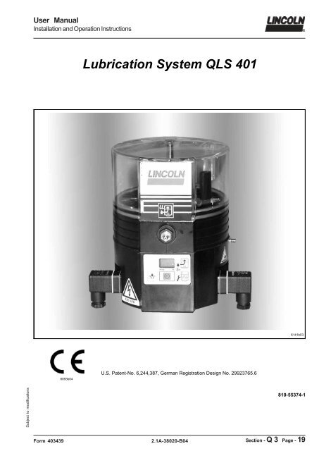
<strong>Lubrication</strong> System QLS <strong>401</strong><br />
U.S. Patent-No. 6,244,387, German Registration Design No. 29923765.6<br />
2.1A-38020-B04<br />
6141b03<br />
810-55374-1<br />
Section - Q 3 Page - 19
User Manual<br />
Installation and Operation Instructions<br />
All rights reserved.<br />
Any duplication of this Owner Manual, in its entirety or in part,<br />
by whatever means is prohibited without the prior consent in<br />
writing of <strong>Lincoln</strong> GmbH & CO. KG.<br />
Subject to modifications without prior notification.<br />
© 2004 by<br />
LINCOLN GmbH & Co. KG<br />
Postfach 1263<br />
D-69183 Walldorf<br />
Page 2 of 48<br />
Phone: +49 (6227) 33-0<br />
Fax: +49 (6227) 33-259<br />
2.1A-38020-B04 Form 403439<br />
Subject to modificaitons
Subject to modificaitons<br />
User Manual<br />
Installation and Operation Instructions<br />
Form 403439<br />
Table of Content<br />
Page<br />
Introduction ........................................................................ 4<br />
Explanation of Symbols Used ............................................ 4<br />
User’s Responsibility ......................................................... 4<br />
Environmental Protection .................................................. 4<br />
Service .............................................................................. 4<br />
Safety Instructions ............................................................. 5<br />
Appropriate Use ................................................................ 5<br />
Misuse ............................................................................... 5<br />
General Safety Instructions ............................................... 5<br />
Regulation <strong>for</strong> Prevention of Accidents ............................. 5<br />
Operation, Repair and Maintenance .................................. 5<br />
Repair .......................................................................... 5<br />
Operation / Maintenance .............................................. 6<br />
Disposal ............................................................................. 6<br />
Exclusion of Liability .......................................................... 6<br />
Installation ......................................................................... 6<br />
Installation Instructions ...................................................... 7<br />
Pump ................................................................................. 7<br />
SSV Divider Block ............................................................. 7<br />
Cross-porting of the SSV Divider Blocks ........................... 7<br />
Single Output ............................................................... 7<br />
Double and Multiple Outputs ........................................ 7<br />
Check valve ................................................................. 7<br />
Direct (internal) feedback feature ...................................... 8<br />
<strong>Lubrication</strong> Points .............................................................. 9<br />
Installing Zerk-Locks onto Grease Fittings ........................ 9<br />
Connection of Feed Lines ................................................ 10<br />
Filling of reservoir ............................................................ 10<br />
Electrical connection ....................................................... 10<br />
Option <strong>for</strong> metric fittings ................................................... 11<br />
Description ...................................................................... 12<br />
Selection Guide ............................................................... 14<br />
VDC ................................................................................. 14<br />
VAC ................................................................................. 15<br />
2.1A-38020-B04<br />
Page<br />
Operation ......................................................................... 16<br />
Pump ............................................................................... 16<br />
Pressure Relief Valve ...................................................... 16<br />
Pump Display Window ..................................................... 16<br />
Monitoring time / Malfunction ........................................... 17<br />
Reservoir empties ...................................................... 18<br />
Operator keys of the keypad ............................................ 18<br />
Additional lube cycle ................................................... 18<br />
Reset of the pause time ............................................. 18<br />
Acknowledging receipt of a malfunction ..................... 19<br />
Display of the set pause time ..................................... 19<br />
Changing to the different programming levels ............ 19<br />
Monitoring relay ............................................................... 19<br />
Setting and Operation .......................................................20<br />
General ............................................................................ 20<br />
Factory Settings ......................................................... 20<br />
Operator keys ............................................................. 20<br />
Display Mode ................................................................... 21<br />
Operating Mode ............................................................... 22<br />
Programming Mode ......................................................... 25<br />
Maintenance, Repair and Tests ....................................... 29<br />
Maintenance .................................................................... 29<br />
To fill reservoir ............................................................ 29<br />
First filling of a lubrication system ............................... 30<br />
Repair .............................................................................. 30<br />
Functional Test ................................................................ 30<br />
Troubleshooting ............................................................... 31<br />
Pump of the QLS <strong>401</strong> system .......................................... 31<br />
SSV divider block ............................................................. 32<br />
Technical Data.................................................................. 34<br />
QLS <strong>401</strong>, General ....................................................... 34<br />
Electrical Data ............................................................ 34<br />
Time Setting ............................................................... 34<br />
Relay <strong>for</strong> Malfunction (Option) .................................... 34<br />
Lines ........................................................................... 35<br />
Tightening Torques .................................................... 35<br />
Accessory Kits ............................................................ 35<br />
Dimensions ...................................................................... 35<br />
Pump .......................................................................... 35<br />
SSV divider blocks ..................................................... 35<br />
Electrical connection ........................................................ 36<br />
Lubricants ........................................................................ 38<br />
Lubricating greases <strong>for</strong> QuickLub systems ................. 39<br />
Biodegradable greases .............................................. 39<br />
Service Parts .................................................................... 40<br />
Explosion view and Parts list with<br />
bottom mounted SSV divider block................................... 40<br />
Explosion view and Parts list with<br />
back mounted SSV divider block ..................................... 42<br />
Declaration of con<strong>for</strong>mity ................................................. 44<br />
Page 3 of 48
User Manual<br />
Installation and Operation Instructions<br />
Explanation of Symbols Used<br />
The following description standards are used in this manual:<br />
Safety Instructions<br />
Structure of safety instructions:<br />
� Pictogram<br />
� Signal word<br />
� Danger text<br />
- Danger note<br />
- How to avoid danger<br />
The following pictograms are used in this manual and are<br />
combined with the corresponding signal words:<br />
1013A94<br />
Page 4 of 48<br />
4273a00<br />
6001a02<br />
- ATTENTION - ATTENTION - NOTE<br />
- CAUTION - CAUTION - IMPORTANT<br />
- WARNING - WARNING<br />
The signal words give the seriousness of danger if the following<br />
text is not observed:<br />
ATTENTION refers to faults or damages on<br />
machines.<br />
CAUTION refers to bad damages and possible<br />
injuries.<br />
WARNING refers to possible dangerous injuries.<br />
NOTE refers to improvements in handling<br />
of systems.<br />
IMPORTANT refers to considerable disadvantages<br />
in handling of systems.<br />
Example:<br />
1013A94<br />
ATTENTION!<br />
When making use of other than the original<br />
spare parts, serious damage may<br />
affect your device.<br />
There<strong>for</strong>e, <strong>for</strong> the operation of your device<br />
always use original spare parts made by<br />
<strong>Lincoln</strong> GmbH & Co. KG.<br />
Introduction<br />
Furthermore, you will find the following text symbols in this<br />
manual:<br />
� Listing of applicable statements<br />
- Subpoint of applicable statements<br />
1. Determination of the number or sequence of contents<br />
� Procedural instruction<br />
User's Responsibility<br />
To ensure the safe operation of the unit, the user is responsible<br />
<strong>for</strong> the following:<br />
1. The pump / system shall be operated only <strong>for</strong> the intended<br />
use (see next chapter "Safety Instructions") and<br />
its design shall neither be modified nor trans<strong>for</strong>med.<br />
2. The pump / system shall be operated only if it is in a<br />
proper functioning condition and if it is operated in accordance<br />
with the maintenance requirements.<br />
3. The operating personnel must be familiar with this Owner<br />
Manual and the safety instructions mentioned within and<br />
observe these carefully.<br />
The correct installation and connection of tubes and hoses, if<br />
not specified by <strong>Lincoln</strong> GmbH & Co. KG, is the user's responsibility.<br />
<strong>Lincoln</strong> GmbH & Co. KG will gladly assist you<br />
with any questions pertaining to the installation.<br />
Environmental Protection<br />
Waste (e.g. used oil, detergents, lubricants) must be disposed<br />
of in accordance with relevant environmental regulations.<br />
Service<br />
The personnel responsible <strong>for</strong> the handling of the pump /<br />
system must be suitably qualified. If required, <strong>Lincoln</strong> GmbH<br />
& Co. KG offers you full service in the <strong>for</strong>m of advice, on-site<br />
installation assistance, training, etc. We will be pleased to<br />
in<strong>for</strong>m you about our possibilities to support you purposefully.<br />
In the event of inquiries pertaining to maintenance, repairs<br />
and spare parts, we require model specific data to enable us<br />
to clearly identify the components of your pump / system.<br />
There<strong>for</strong>e, always indicate the part, model and series number<br />
of your pump / system.<br />
2.1A-38020-B04 Form 403439<br />
Subject to modificaitons
Subject to modificaitons<br />
User Manual<br />
Installation and Operation Instructions<br />
Appropriate Use<br />
The lubrication system QLS <strong>401</strong> has been designed <strong>for</strong> initial<br />
and retrofit installation. It has been designed <strong>for</strong>:<br />
� the automatic lubrication of machines and systems<br />
� the automatic lubrication of commercial vehicles and construction<br />
machines<br />
� the automatic lubrication of hydraulically driven units and<br />
devices.<br />
The lubrication system QLS <strong>401</strong> is able to deliver greases up<br />
to NLGI - class 2 or fluid greases of NLGI - class 000 or 00.<br />
� Use the QLS <strong>401</strong> exclusively to supply lubricants.<br />
� The QLS <strong>401</strong> is adequate <strong>for</strong> intermittent operation only.<br />
� The QLS <strong>401</strong> is adequate <strong>for</strong> feeding max. 18 lube points<br />
per lube cycle.<br />
� Do not use QLS <strong>401</strong> with SSV divider block in bottom<br />
mounting position <strong>for</strong> mobile applications. Do not install<br />
the system with machines exposed to shock.<br />
Misuse<br />
Any use of the QLS <strong>401</strong> that is not expressly mentioned in<br />
this Owner Manual will be regarded as misuse.<br />
If the QLS <strong>401</strong> is used or operated in a different manner other<br />
than specified, any claim <strong>for</strong> warranty or liability will be null<br />
and void.<br />
NOTE<br />
If personal injury or material damage<br />
occurs as a result of inappropriate operation,<br />
e.g. if the safety instructions are<br />
6001a02 ignored or resulting from an incorrect<br />
installation of the QLS <strong>401</strong>, no claims or<br />
legal actions may be taken against<br />
<strong>Lincoln</strong> GmbH & Co. KG.<br />
Regulations <strong>for</strong> Prevention of Accidents<br />
To prevent accidents, observe all city, state and federal<br />
safety regulation of the country in which the product will be<br />
used.<br />
General Safety Instructions<br />
� <strong>Lubrication</strong> systems QLS <strong>401</strong><br />
- are designed state-of-the-art.<br />
- can be assembled <strong>for</strong> safe operation.<br />
- must be filled regularly without air inclusions with clean<br />
lubricant recommended by the manufacturer (see page<br />
40 ff).<br />
Form 403439<br />
Safety Instructions<br />
2.1A-38020-B04<br />
General Safety Instructions, continuation<br />
� Incorrect use may result in bearing damage caused by<br />
poor or over-lubrication.<br />
� Do not over-pressurize reservoir when filling the pump.<br />
Refill QLS <strong>401</strong> pump with clean lubricant.<br />
� Each outlet needed must be equipped with an appropriate<br />
check valve.<br />
IMPORTANT<br />
Do not paint the pump. Be<strong>for</strong>e painting a<br />
machine or commercial vehicle, remove<br />
or cover the pump completely.<br />
6001a02<br />
� Unauthorized modifications or changes to an installed<br />
system are not recommended and will void warranty. Any<br />
modifications must be subject to prior consultation with<br />
the manufacturer of the QLS <strong>401</strong>.<br />
Operation, Repair and Maintenance<br />
1013A94<br />
4273a00<br />
ATTENTION!<br />
Malfunction because of dirt!<br />
When executing any maintenance or<br />
repair works on the QLS <strong>401</strong>, ensure<br />
absolute cleanliness.<br />
CAUTION!<br />
For pumps with 120 VAC and 230 VAC,<br />
switch off the power supply be<strong>for</strong>e beginning<br />
maintenance or repair work.<br />
Repair<br />
Repairs should only be per<strong>for</strong>med by authorized personnel<br />
who are familiar with the instructions.<br />
Operation with bayonet plug<br />
CAUTION!<br />
If the protective-conductor terminal is not<br />
connected or interrupted, dangerous<br />
touch voltages may occur on the<br />
equipment!<br />
4273a00<br />
Protective measures to be applied <strong>for</strong> the appropriate operation<br />
with bayonet plugs:<br />
"Functional extra-low voltage with safe isolation" /<br />
"Protective Extra-Low Voltage" (PELV)<br />
Standards: EN60204 Part1:1992 / IEC 204-1:1992, modified<br />
DIN VDE 0100 Part (see page 39 and 40)<br />
Page 5 of 48
User Manual<br />
Installation and Operation Instructions<br />
Operation, Repair and Maintenance,<br />
continuation<br />
Operation/Maintenance<br />
<strong>Lubrication</strong> systems QLS <strong>401</strong><br />
� must operate with mounted pressure relief valve, only.<br />
� must operate only with mounted or connected SSV divider<br />
blocks.<br />
� must be filled regularly without air inclusions with clean<br />
lubricant recommended by the manufacturer.<br />
� operates automatically. However, a regular check (according<br />
to the fixed lubrication intervals) should be made<br />
to ensure that lubricant is being dispensed from all lubricant<br />
points.<br />
Repair<br />
Repairs should only be per<strong>for</strong>med by authorized personnel<br />
who are familiar with the instructions.<br />
Disposal<br />
Dispose of used or contaminated lubricants as well as of<br />
parts that were in touch with lubricant according to the legal<br />
regulations pertaining to environmental protection. Make sure<br />
to observe the safety data sheets of the lubricants used.<br />
Exclusion of Liability<br />
The manufacturer of the centralized lubrication system QLS<br />
<strong>401</strong> will not accept any liability <strong>for</strong> damages:<br />
� caused by insufficient lubricant and irregular refilling of<br />
pump.<br />
� due to the use of greases which are not or are only conditionally<br />
pumpable in centralized lubrication systems.<br />
� caused by the use of contaminated lubricants.<br />
� caused by an environmentally inadequate disposal of<br />
used or contaminated lubricants or parts that were in<br />
touch with lubricants.<br />
� caused by unauthorized modification of system components.<br />
� caused by the use of unapproved parts (voids the pump<br />
warranty).<br />
Installation<br />
6001a02<br />
Page 6 of 48<br />
Safety Instructions, continuation<br />
IMPORTANT<br />
Do not remove, modify or alter any safety<br />
equipment already installed on the<br />
machine.<br />
� If necessary, these devices may be<br />
removed temporarily during the installation<br />
of the pump.<br />
� The devices must be properly put<br />
back in place after the installation of<br />
the pump.<br />
Installation, continutation<br />
� Use only original spare parts or spare parts authorized by<br />
<strong>Lincoln</strong>.<br />
� Keep the centralized lubrication system QLS <strong>401</strong> away<br />
from sources of heat. Observe the operating temperatures<br />
(see page 35, chapter "Technical Data")..<br />
� Provide access to fill, clean and visually monitor the pump<br />
operation.<br />
IMPORTANT<br />
Follow installation instructions of the<br />
OEM regarding minimum distances<br />
between the drilled holes and welding<br />
6001a02 procedures.<br />
4273a00<br />
4273a00<br />
4273a00<br />
WARNING!<br />
Failure to observe the safety instructions,<br />
e. g. touching electrically charged parts<br />
when the system is opened, or improper<br />
handling of the QLS <strong>401</strong> may cause<br />
serious injury or death.<br />
If the values specified in the Technical<br />
Data are exceeded, the device may<br />
overheat. It may damage the QLS <strong>401</strong><br />
and thus impair the electric safety.<br />
CAUTION!<br />
The QLS <strong>401</strong> may only be installed by<br />
qualified personnel. The connection<br />
(N/L/PE) of the supply voltage must be<br />
made according to VDE 0100 and<br />
VDE 0160.<br />
Install a protective and lock out device <strong>for</strong><br />
isolating and disconnecting the QLS <strong>401</strong>.<br />
Be<strong>for</strong>e beginning the installation work,<br />
disconnect the electrical supply.<br />
ATTENTION!<br />
Consider residual ripple of max. ±5 % to<br />
connect pumps with direct current<br />
version (in relation to the operating<br />
voltage acc. to DIN 41755).<br />
2.1A-38020-B04 Form 403439<br />
Subject to modificaitons
Subject to modificaitons<br />
User Manual<br />
Installation and Operation Instructions<br />
Pump<br />
Use drilling template to mark and drill mounting holes of the<br />
QLS <strong>401</strong>. Drilling template and mounting bolts are included in<br />
the package.<br />
SSV Divider Block<br />
Fig. 1 Single double and triple lubricant output, on rear side<br />
mounted divider blocks<br />
0x-3x Outlet quantity (single, double, etc.)<br />
1-6 Outlet numbers<br />
A Clamping ring (brass)<br />
B Grease supply<br />
C Enclosed grease<br />
R Return to reservoir<br />
Fig. 2 Closure plug, also provided in the accessory kits<br />
Fig. 3 Check valve, push-in type<br />
A Clamping ring (brass)<br />
Form 403439<br />
Installation Instructions<br />
1014b00<br />
4163a98<br />
4180a02<br />
2.1A-38020-B04<br />
Crossporting of the SSV Divider Blocks<br />
Single Output<br />
A single output is the lubricant quantity fed to the lube point<br />
by a piston per stroke and outlet port. It amounts to approximately<br />
0.2 cm³, see outlet 6, fig. 1.<br />
Double or Multiple Outputs<br />
� Outputs can be increased by simply plugging the unused<br />
outlet ports with closure plugs (fig. 2, provided in the accessory<br />
kit).<br />
� Lubricant from a plugged outlet is redirected to the next<br />
outlet on the same side of the SSV divider block in descending<br />
numerical order (see fig.1).<br />
� Example, see fig. 1:<br />
By closing<br />
- of outlet 4, outlet 2 receives the double quantity.<br />
- of outlets 5 and 3, outlet 1 receives the triple amount of<br />
lubricant. The connecting conduit from outlet line 1 to<br />
outlet line 2 and to the return line (R) is closed by<br />
clamping rings (A) of the check valve.<br />
� Unused lubricant can be internally fed back to the reservoir,<br />
see paragraph ‘’direct internal feed back feature”.<br />
NOTE<br />
Do not plug outlets number 1 and 2<br />
(horizontally positioned outlets) on<br />
bottom-mounted lubricant divider blocks<br />
6001a02 SSV 8, 12 and 18.<br />
Do not plug outlets number 1 or 2 on<br />
externally mounted divider blocks.<br />
Closure plug<br />
� Install a closure plug in each outlet port hole which is not<br />
required, see fig. 1 or 4.<br />
� Closure are used in fig. 1 and 4 as follows:<br />
- Fig. 1 outlets 3, 4 and 5<br />
- Fig. 4 (page 8) outlets 1, 2, 4 and 5<br />
Check valve<br />
� For the connection to pressure plastic tubes and highpressure<br />
hoses see page 11, fig. 11.<br />
� Install a check valve in each outlet port hole which is required<br />
(observe paragraph “Direct (internal) feedback feature”<br />
on page 8).<br />
Page 7 of 48
User Manual<br />
Installation and Operation Instructions<br />
Page 8 of 48<br />
Installation Instructions, continuation<br />
4188b99<br />
Fig. 4 Internal feedback of supplied lubricant, only on rear-side<br />
mounted SSV divider blocks<br />
0x-2x Outlet quantity (single, double, etc.)<br />
1-6 Outlet numbers<br />
A Clamping ring (brass)<br />
B Grease supply<br />
C Enclosed grease<br />
R Return line bore hole<br />
6001a02<br />
NOTE<br />
Maximum internal combination of<br />
outlets:<br />
SSV 6 = 3<br />
SSV 12 = 6<br />
SSV 18 = 9<br />
Further combinations are possible<br />
outside the divider valve by means of a<br />
tee-piece only.<br />
Direct (internal) feedback feature<br />
� All pumps with back- mounted SSV divider block have<br />
the capability to feed back unused lubricant internally from<br />
closed outlets directly to the reservoir (see R fig. 1, 4).<br />
� This procedure will start automatically, if outlet port 2 is<br />
plugged with a closure plug. All pumps have capability to<br />
feed back the lubricant directly to the reservoir from even<br />
and odd outlets via the channel from outlet 1 to outlet 2 .<br />
� Start from the smallest outlet number when closing the<br />
outlets, <strong>for</strong> instance 2, 4, 6 on even side or 1, 3, 5 on odd<br />
side plus outlet 2. In fig. 4 the quantities of outlets 1, 2 and<br />
4 (3xR) are fed back to the reservoir.<br />
� The remaining outlets are to be used <strong>for</strong> the connection to<br />
the lube point or <strong>for</strong> increasing the lubricant quantity (double<br />
or triple), see fig.1.<br />
1013A94<br />
6001a02<br />
CAUTION!<br />
To change the outlet 2 <strong>for</strong> bearing lubrication,<br />
replace closure plug with check<br />
valve (Fig. 3), then never close outlet<br />
(see page 7, fig. 1, pos. 1).<br />
NOTE<br />
To feed back unneeded lubricant quantities<br />
from bottom- mounted divider<br />
blocks to the reservoir, connect unneeded<br />
outlet via the feedline to plug 5<br />
(page 13, fig. 15, 16) <strong>for</strong> external return<br />
line.<br />
2.1A-38020-B04 Form 403439<br />
Subject to modificaitons
Subject to modificaitons<br />
User Manual<br />
Installation and Operation Instructions<br />
<strong>Lubrication</strong> Points<br />
Installing Quicklinc fittings into lube points<br />
Remove hydraulic lube fittings from lube points and install<br />
appropriate Quicklinc fittings into the bore holes of the lube<br />
points.<br />
Installing Zerk-Locks onto Grease Fittings<br />
Form 403439<br />
4200a99<br />
Fig. 5 Place the Zerk-Lock<br />
body over the grease<br />
fitting<br />
Installation Instructions, continuation<br />
4201a99<br />
Fig. 6 Installation of Zerk-<br />
Locks with staking tool<br />
Fig. 7 Screwing Quicklinc fitting into the Zerk-Lock body<br />
4202a99<br />
2.1A-38020-B04<br />
The Zerk-Lock fitting consists of the Zerk-Lock body, insert<br />
and a Quicklinc fitting.<br />
� Place the Zerk-Lock body over the grease fitting and<br />
place the staking tool firmly against the Zerk-Lock insert.<br />
� Strike the tool sharply with a hammer until the Zerk-Lock<br />
insert partially crimps onto the grease fitting (only with<br />
US version necessarily).<br />
� Screw the Quicklinc fitting into the Zerk-Lock body and<br />
tighten until parts resist further tightening (about 1-1/2<br />
turns).<br />
NOTE<br />
Quicklinc hex. is 12 mm. Zerk-Lock body<br />
hex is 1/2 ’’.<br />
6001a02<br />
� Move the Zerk-Lock and tube fitting from side to side on<br />
the grease fitting to insure the Zerk-Lock is firmly seated.<br />
Page 9 of 48
User Manual<br />
Installation and Operation Instructions<br />
Connection of Feed Lines<br />
Fig. 8 Feed line installed in the Quicklinc fitting<br />
Page 10 of 48<br />
Installation Instructions, continuation<br />
4203a99<br />
Fig. 9 Feed line insert into the fitting up to the next white mark<br />
Filling of reservoir<br />
� Fill the reservoir with suitable clean lubricant (see page<br />
29).<br />
CAUTION!<br />
Observe safety instructions on page 29,<br />
chapter “To fill reservoir“!<br />
1013A94<br />
4157a98<br />
� Measure, cut and route the feed lines included in the kit.<br />
NOTE<br />
Avoid sharp bends of the plastic tubing<br />
and the moving parts of the machine that<br />
could damage the lubrication lines.<br />
6001a02 Minimum bending radius is 50 mm (2 in).<br />
� Secure the lubrication lines to the machine using nylon ties,<br />
clamps or straps provided in the accessory kit.<br />
� If the feed lines are not primed, prime all lubrication feed<br />
lines be<strong>for</strong>e connecting them to the lube point (see page<br />
29, paragraph “First Filling of a lubrication system”).<br />
� Connect the feed lines directly to the check valves of the<br />
divider block and to the Quicklinc fittings of the lube point.<br />
NOTE<br />
6001a02<br />
Push the ends of the feed lines firmly into<br />
the Quicklinc fittings until they are fully<br />
seated in the body of the fitting. The<br />
primed feed lines are marked with white<br />
lines (fig. 9) to facilitate installation.<br />
� Cut off the pressure plastic tube uprightly at one of the<br />
white lines be<strong>for</strong>e it is mounted.<br />
� Then insert the plastic pressure tube into the fitting up to<br />
the next white mark.<br />
This will ensure a correct installation of the pressure plastic<br />
tube in the threaded tube fitting.<br />
Electrical connection<br />
� Connect the electrical wires according to the following<br />
electrical connecting diagrams (see page 37 to 40).<br />
CAUTION!<br />
Observe safety instructions on page 37,<br />
chapter “Electrical connection”!<br />
4273a00<br />
4273a00<br />
ATTENTION!<br />
Consider residual ripple of max. ±5 % to<br />
connect pumps with direct current version<br />
(in relation to the operating voltage acc.<br />
to DIN 41755).<br />
2.1A-38020-B04 Form 403439<br />
Subject to modificaitons
Subject to modificaitons<br />
User Manual<br />
Installation and Operation Instructions<br />
Option <strong>for</strong> metric fittings<br />
(to order separately)<br />
SSV Connecting tube fitting, screw-type and push-in type<br />
Fig. 10 Screw-type check valve<br />
Form 403439<br />
Installation Instructions, contiuation<br />
4239a99<br />
Connection of pressure plastic tubes and high-pressure hoses<br />
Fig. 11 Different types of check valves<br />
1009a98<br />
4156a98<br />
Fig. 12 Check valve with rein<strong>for</strong>ced pliers and high-pressure hose<br />
2.1A-38020-B04<br />
1 Ferrule nut<br />
2 Cutting ring<br />
3 Valve body with sealing and ferrule<br />
� For high-pressure hose (NW 4.1 x 2.3 mm) use check<br />
valve A, fig. 11, with rein<strong>for</strong>ced collets 1a and smooth<br />
flange (part no. 226-14091-4)<br />
� For pressure plastic tube (dia. 6 x 1.5 mm) use check<br />
valve B, fig. 11, with standard pliers 2a and knurled flange<br />
(part no. 226-14091-2)<br />
A Check valve with rein<strong>for</strong>ced collets<br />
B Check valve with standard collets<br />
1a Smooth flange<br />
2a Knurled flange<br />
6001a02<br />
6001a02<br />
NOTE<br />
On construction machines or agricultural<br />
machines use high-pressure hoses as<br />
feedlines. In such cases, the check<br />
valves of the sub-divider blocks must<br />
have rein<strong>for</strong>ced collets and a smooth<br />
flange.<br />
IMPORTANT<br />
Connect only high-pressure hoses (NW<br />
4.1 x 2.3 mm) with threaded sleeve and<br />
hose stud to the check valves with rein<strong>for</strong>ced<br />
pliers.<br />
Page 11 of 48
User Manual<br />
Installation and Operation Instructions<br />
Option <strong>for</strong> metric fittings, continuation<br />
(to order separately)<br />
Page 12 of 48<br />
Installation Instructions, continuation<br />
Mounting of the threaded sleeves and hose studs onto the high-pressure hose<br />
1028a96<br />
Fig. 13 Pre-assembly of the threaded sleeves and hose studs onto<br />
the main line<br />
Fig. 14 QLS <strong>401</strong> with back position of the SSV divider block<br />
1 Proximity switch<br />
2 Control pin<br />
3 SSV divider block<br />
4 Nipple <strong>for</strong> external manual lubrication (1/8’’)<br />
Description<br />
4198b04<br />
� Screw threaded sleeve (1, fig. 13) counterclockwise onto<br />
the high-pressure hose (2) until the illustrated dimension<br />
of 11mm is reached. Then screw the hose stud (3) into<br />
the threaded sleeve (1).<br />
IMPORTANT<br />
Oil parts 1 and 3 well be<strong>for</strong>e screwing<br />
them together.<br />
6001a02<br />
1 Threaded sleeve<br />
2 High-pressure hose (main line)<br />
3 Hose stud<br />
� The QLS <strong>401</strong> is a complete compact lubrication system<br />
<strong>for</strong> a maximum of 18 lubrication points per cycle.<br />
� The pump has three basic configurations:<br />
- SSV divider block mounted on the back (see Fig. 14)<br />
- SSV divider block mounted on the bottom (see Fig. 15)<br />
- Pump without the SSV divider block attached respectively<br />
with external divider block SSV KNQLS (see fig.<br />
16)<br />
� Standard lubrication lines are high-pressure hoses <strong>for</strong><br />
pumps with the SSV divider block attached.<br />
� The pump with the SSV divider block mounted on the<br />
bottom has the capability of using also steel tubing as lubrication<br />
lines if necessary.<br />
NOTE<br />
6001a02<br />
The function of the pump is independent<br />
of the SSV divider block's mounting position.<br />
2.1A-38020-B04 Form 403439<br />
Subject to modificaitons
Subject to modificaitons<br />
User Manual<br />
Installation and Operation Instructions<br />
Fig. 15 QLS <strong>401</strong> with bottom position of the SSV divider block<br />
Form 403439<br />
Description, continuation<br />
4199b04<br />
6178b04<br />
Fig. 16 QLS <strong>401</strong> without mounted SSV divider valve with connection<br />
<strong>for</strong> external SSV divider valve KN QLS<br />
1 Connecting block<br />
2 Closure plug<br />
3 Nipple <strong>for</strong> emergency lubrication, R 1/8’<br />
4 Connecting socket <strong>for</strong> SSV KN QLS<br />
P For feedline to external SSV KN QLS<br />
R Relief line connection<br />
2.1A-38020-B04<br />
� A signal from the pump timer starts the electric motor and<br />
the pumping element starts pumping the lubricant to the<br />
SSV divider block.<br />
� When all lubrication points have received lubricant, an<br />
internal proximity switch 1 Fig. 14 turns the motor off,<br />
completing one lubrication cycle.<br />
� If the pump does not complete the cycle within 15 minutes<br />
of operation, the alarm indication ”Er” will be displayed as<br />
a flashing light in the keypad window, see page 17 fig. 21.<br />
1 Connecting block<br />
2 Manifold<br />
3 SSV divider block<br />
4 Nipple <strong>for</strong> external manual lubrication (1/8’’)<br />
5 Plug (1/8’’) <strong>for</strong><br />
P external pressure line<br />
R external return line<br />
� An externally connected lubricant divider valve SSV KN<br />
QLS is equipped with the same proximity switch as the<br />
normal QLS <strong>401</strong>.<br />
� The proximity switch is provided with a connecting cable<br />
of 2 m lengths and a connecting plug which must be<br />
connected to the socket (pos. 4) of the QLS <strong>401</strong>.<br />
� The socket is integrated in the housing instead of the<br />
proximity switch and is connected to the control p.c.b.<br />
NOTE<br />
The function of the QLS <strong>401</strong> is independent<br />
of the mounting position of the<br />
proximity switch.<br />
6001a02<br />
There are available the following externally connectable divider<br />
valves SSV KN QLS:<br />
- SSV 6 KN QLS 619-28945-1<br />
- SSV 8 KN QLS 619-28946-1<br />
- SSV 10 KN QLS 619-28949-1<br />
- SSV 12 KN QLS 619-28950-1<br />
- SSV 14 KN QLS 619-28951-1<br />
- SSV 16 KN QLS 619-28952-1<br />
- SSV 18 KN QLS 619-28953-1<br />
Page 13 of 48
User Manual<br />
Installation and Operation Instructions<br />
Page 14 of 48<br />
Selection Guide VDC<br />
Pump models P<strong>401</strong>00400113<br />
Examples of part numbers P<strong>401</strong>62400153<br />
P<strong>401</strong> 6 2 4 0 0 1 5 3<br />
Pump <strong>401</strong> <strong>for</strong> grease ........................................................... P<strong>401</strong><br />
SSV Divider Block<br />
External, SSV 6, SSV 8 2) (or SSV 12 and 18 without control p.c.b.)<br />
External, SSV 12, SSV 18 2) 0<br />
.................................................. . 1<br />
SSV 6 (back) ........................................................................ 3<br />
SSV 8 (bottom) ..................................................................... 4<br />
SSV 12 ................................................................................. 6<br />
SSV 18 ................................................................................. 9<br />
2)<br />
Hinweis: Für externe Verteileranwendung nur die dafür vorgesehenen SSV...KNQLS Verteiler<br />
verwenden. Für Pumpen ohne Verteiler ist eine Abschaltung des <strong>Systems</strong> nur durch eine externe<br />
Steuerung oder SPS möglich.<br />
SSV Divider Block Position<br />
External divider block.............................................................<br />
Back (vertical order) ..............................................................<br />
Bottom 3) (horizontal order) ....................................................<br />
3)<br />
Note: Do not use QLS <strong>401</strong> with SSV block in bottom-mounting position <strong>for</strong> mobile applications. Do not<br />
install the pump in areas exposed to shock.<br />
Operating Voltage<br />
12 VDC 1) ................................................................................<br />
24 VDC 1) 2<br />
................................................................................ 4<br />
1)<br />
Note: Standard 12 and 24 VDC pump models <strong>for</strong> mobile applications can be supplied with 10-meter (30’)<br />
electrical cable.<br />
Reservoir with an without Low-level control<br />
1 L reservoir without low level control ................................... 0<br />
Number of Possible Connections<br />
- 1A = connection left-side (square-type), supply voltage<br />
- 2A = 2 connections (square-type)<br />
1 connection left-side, supply voltage<br />
1 connection right-side, low-level control or fault indication<br />
1A = 1 connection (quarter-turn type) supply voltage;<br />
low-level control or fault indication .............................<br />
Type of Plug Connector<br />
* Square-type, acc. to DIN 43650 type of construction A<br />
(industrial application) ........................................................<br />
** Quarter-turn type plug, DIN 72585-1, 4-pole<br />
(mobile application) ...........................................................<br />
Electrical Connectors<br />
With socket, without cable * ..................................................<br />
With socket, with cable 10 m * ..............................................<br />
With socket, with cable 10 m, ADR *<br />
With socket, with cable 10 m **..............................................<br />
With socket, with cable 10 m, ADR **<br />
Control p. c. b.<br />
p. c. b. without time control ....................................................<br />
p. c. b. S3:<br />
Normally closed or normally open contact (programmable), monitored:<br />
1 to 5 cycles.................................................................<br />
0<br />
1<br />
2<br />
0<br />
1<br />
2<br />
1<br />
5<br />
1<br />
5<br />
6<br />
7<br />
8<br />
0<br />
3<br />
(Accessory kits, see chapter ”Technical Data“)<br />
2.1A-38020-B04 Form 403439<br />
Subject to modificaitons
Subject to modificaitons<br />
User Manual<br />
Installation and Operation Instructions<br />
Form 403439<br />
Selection Guide VAC<br />
Pump models P<strong>401</strong>00800113<br />
Examples of part numbers P<strong>401</strong>62400153<br />
P<strong>401</strong> 6 2 4 0 0 1 5 3<br />
Pump <strong>401</strong> <strong>for</strong> grease .......................................................... P<strong>401</strong><br />
SSV Divider Block<br />
External, SSV 6, SSV 8 2) (or SSV 12 and 18 without control p.c.b.)<br />
External, SSV 12, SSV 18 2) .................................................. .<br />
0<br />
1<br />
SSV 6 (back) ........................................................................ 3<br />
SSV 8 (bottom) ..................................................................... 4<br />
SSV 12 ................................................................................. 6<br />
SSV 18 ................................................................................. 9<br />
2)<br />
Note: For external divider block application only use the specific divider blocks SSV ... KNQLS.<br />
SSV Divider Block Position<br />
External divider block ............................................................<br />
Back (vertical order) ..............................................................<br />
Bottom 3) 0<br />
1<br />
(horizontal order) ................................................... 2<br />
3)<br />
Note: Do not use QLS <strong>401</strong> with SSV block in bottom-mounting position <strong>for</strong> mobile applications. Do not<br />
install the pump in areas exposed to shock.<br />
Operating Voltage<br />
120 VAC 1) (with control p.c.b. only) ......................................<br />
230 VAC 1) 6<br />
(with control p.c.b. only) ...................................... 8<br />
1)<br />
Note: Standard 120 and 230 VAC pump models <strong>for</strong> industry are supplied without electrical cable.<br />
Reservoir with an without Low-level control<br />
1 L reservoir without low level control ................................... 0<br />
Number of Possible Connections<br />
- 1A = 1 connection left-side, supply voltage ........................<br />
- 2A = 2 connections (square-type)<br />
1 connection left-side, supply voltage<br />
1 connection right-side, low-level control or fault indication<br />
Type of Plug Connector<br />
* Square-type, acc. to DIN 43650 type of construction A.......<br />
Electrical Connectors<br />
With socket, without cable* ...................................................<br />
With socket, with cable 10 m* ...............................................<br />
Control p. c. b.<br />
p. c. b. S3:<br />
Normally open or normally closed contact (programmable),<br />
monitored<br />
- 1 cycle with SSV 12, SSV 18<br />
- 1 to 3 cycles with SSV 6, SSV 8 .........................................<br />
0<br />
1<br />
1<br />
1<br />
5<br />
3<br />
2.1A-38020-B04<br />
(Accessory kits, see chapter ”Technical Data”)<br />
Page 15 of 48
User Manual<br />
Installation and Operation Instructions<br />
Pump<br />
Fig. 17 QLS <strong>401</strong> unit<br />
Pressure Relief Valve<br />
Fig. 18 Pressure relief valve (cartridge) in housing<br />
Pump Display Window<br />
Fig. 19 Green decimal point (pause time)<br />
Fig. 20 Green display (operating time)<br />
Page 16 of 48<br />
4208a04<br />
4209a99<br />
Operation<br />
4205b03<br />
4304a00<br />
� The QLS <strong>401</strong> operates according to lube cycles (pause<br />
and operating times).<br />
� With standard setting the pause time begins the cycle,<br />
then the operating time occurs.<br />
This can be changed by reprogramming the start stage<br />
(see page 27).<br />
� A division of the lube points (option) via sub-divider<br />
blocks and one main divider block (SSV 6, SSV 8) is<br />
possible only up to max. 18 points per cycle. In this<br />
case, the number of the cycles of the main divider block<br />
must be set (see P3 on page 24).<br />
1 Proximity switch<br />
2 Keypad with display<br />
3 Control unit<br />
4 Pump unit<br />
5 SSV 6, 8, 12, 18<br />
� The QLS <strong>401</strong> is protected with a pressure relief valve<br />
(cartridge).<br />
� The pressure relief valve limits the pressure build-up in<br />
the QLS <strong>401</strong>. It opens at an overpressure of 205 bar<br />
(3000 psi).<br />
� If the pressure relief valve is actuated, this indicates that<br />
the system is malfunctioning. The lubricant flows back<br />
into the reservoir (hardly visible).<br />
� Upon expiration of the monitoring time of 15 minutes<br />
(VAC models) or 25 minutes (VDC models), the pump<br />
switches off. The fault indication ”Er” is displayed on the<br />
keypad of the pump. See ”Display mode” under ”Control<br />
unit”.<br />
� Pump ”On” is indicated on the display by an illuminated<br />
rung on the right (pause time is running).<br />
� Pump ”running” is indicated on the display by a rotating<br />
light movement of the green display (operating time).<br />
� If the voltage supply is interrupted during the operating<br />
time, the times already expired are stored. When the<br />
power supply is switched on again, the operating time<br />
continues operating from the point where it had been<br />
interrupted.<br />
2.1A-38020-B04 Form 403439<br />
Subject to modificaitons
Subject to modificaitons<br />
User Manual<br />
Installation and Operation Instructions<br />
Monitoring time/ malfunction<br />
Fig. 21 Display of a fault indication<br />
Fig. 22 Keypad with showing a malfunction<br />
Form 403439<br />
Operation, continuation<br />
4210a99<br />
4228b03<br />
1 Display window<br />
2 Operator key<br />
– operating mode: trigger additional lubrication<br />
– programming mode: setting of times and divider<br />
cycles – terminate programming<br />
3 Operator key<br />
– display mode: acknowledge receipt of flashing<br />
functional fault<br />
- operating mode: display of the set pause time and<br />
residual pause time<br />
– programming mode: change to the different<br />
programming levels<br />
2.1A-38020-B04<br />
� If the cycle is not complete within 15 minutes (monitoring<br />
time) after expiration of the pause time, the pump<br />
immediately switches off.<br />
The fault indication ” Er ” (error) is displayed as a flashing<br />
light (see page 12, fig. 14, pos. 1). At the same time, a<br />
potential free contact is available <strong>for</strong> the external fault<br />
indication (option), either as malfunction or as “Reservoir<br />
empty”.<br />
6001a02<br />
IMPORTANT<br />
If a malfunction is present, the pump no<br />
longer switches on automatically.<br />
� Acknowledge the malfunction (pos. 3). The flashing display<br />
changes into permanent light.<br />
� Only in this case, switch on the pump by pressing the<br />
button <strong>for</strong> additional lube cycle (pos. 2).<br />
� When a malfunction is present, it can only be cancelled by<br />
initiating an additional lube cycle and if a proper lube cycle<br />
has been executed afterward.<br />
� If the fault is still present after an additional lube cycle has<br />
been initiated, the fault indication ”Er” is displayed again.<br />
� The monitoring time starts at the same time as the operating<br />
time. It is a fixed time of 15 minutes.<br />
� If the voltage supply is interrupted during the monitoring<br />
phase (operating time), the monitoring time starts from the<br />
beginning after the pump is switched on again.<br />
Page 17 of 48
User Manual<br />
Installation and Operation Instructions<br />
Reservoir empty<br />
Fig. 23 Display of a low-level control<br />
Operator keys of the keypad<br />
Page 18 of 48<br />
4210a99<br />
Operator keys of the keypad in the operating mode<br />
4222a99<br />
Fig. 24 Pushbutton <strong>for</strong> additional lubrication cycle<br />
Operation, continuation<br />
> 2 sec.<br />
Operator keys of the keypad in the programming mode<br />
4222a99<br />
Fig. 25 Key <strong>for</strong> resetting the pause time and terminating the programming<br />
mode<br />
� When the reservoir is nearly empty the pump display<br />
shows ”Er” (see Fig 23).<br />
IMPORTANT<br />
If the reservoir is empty, the pump element<br />
does not supply any lubricant. As a consequence<br />
the proximity switch is not actuated<br />
and the fault indication * ER * is triggered.<br />
6001a02<br />
� Fill reservoir (see page 28).<br />
� Trigger additional lubrication cycles until lubricant leaks<br />
out. The indicator pin (see page 12, fig. 14, pos. 2) moves<br />
across the proximity switch (pos. 1).<br />
� Additional lube cycle<br />
� is triggered via the button (Fig. 24). Press the button <strong>for</strong><br />
2 seconds.<br />
� can be initiated at any time, provided that the power<br />
supply is applied.<br />
� If a fault signal (malfunction) is present, it will be cancelled<br />
as soon as the system is operating properly, again.<br />
NOTE<br />
If a malfunction is present (flashing<br />
display), first acknowledge this<br />
malfunction, see Fig. 26. This is not<br />
6001a02 urgently needed.<br />
� Reset of the pause time and termination of the programming<br />
mode<br />
� Setting of the pause time by<br />
- single key activation <strong>for</strong> one hour/minute<br />
- permanent activation <strong>for</strong> quick run<br />
� Settings of the monitoring relay<br />
Setting of the metering device cycles:<br />
� The monitoring relay signalizes a fault on an external<br />
lamp via the optional connection “X2“ (see connecting wiring<br />
diagrams).<br />
In case of a standard setting “normally open contact” the<br />
fault is indicated by a lamp with permanent light.<br />
In case of a standard setting “normally closed contact” the<br />
fault is indicated by a lamp that does not burn any more.<br />
� For VDC version ……………………………. 1 to 5 cycles<br />
For VAC version<br />
- SSV 6 / SSV 8 ……………………………... 1 to 3 cycles<br />
- SSV 12 / SSV 18 ….……………………….......... 1 cycle<br />
� Start setting<br />
� Setting: SP (Start with pause time)<br />
SO (Start with operating time)<br />
� Termination of the programming mode<br />
� Termination of the programming mode<br />
2.1A-38020-B04 Form 403439<br />
Subject to modificaitons
Subject to modificaitons<br />
User Manual<br />
Installation and Operation Instructions<br />
Operator keys of the keypad, continuation<br />
Operator keys of the keypad in the display mode<br />
Form 403439<br />
4214a99<br />
Fig. 26 Acknowledging receipt of a flashing fault indication<br />
Operator keys of the keypad in the operating mode<br />
4214a99<br />
Operation, continuation<br />
> 2 sec.<br />
Fig. 27 In<strong>for</strong>mation regarding the set pause time and residual<br />
pause time<br />
Operator keys of the keypad in the programming mode<br />
4222a99<br />
4214a99<br />
4214a99<br />
Fig. 28 Changing to the different programming levels<br />
Monitoring relay<br />
2.1A-38020-B04<br />
� Acknowledging receipt of a malfunction<br />
� By pressing the key (Fig. 26) the flashing *Er* changes<br />
into a permanent light.<br />
� Display of in<strong>for</strong>mation regarding the set pause time<br />
and residual pause time<br />
� Press key > 2 seconds.<br />
� Changing to the different programming levels<br />
� Press key to change into the programming mode.<br />
� Setting: hours ..................................................... P1<br />
minutes ................................................. P2<br />
Output external fault contact ..................<br />
P4 External indication of a failure<br />
regarding the normally open or<br />
normally closed contact function ........... P5<br />
Starting with pause time or<br />
operating time........................................ P6<br />
� Termination of programming<br />
� The monitoring relay signalizes a malfunction (only in<br />
combination with optional connector X2, see electrical<br />
connection diagrams).<br />
� In the first case the relay picks up (normally open contact).<br />
� In the second case the relay releases (normally closed<br />
contact, broken-wire interlock).<br />
� The signal is available via a potential free contact.<br />
� The monitoring relay is released upon acknowledgement<br />
of the fault.<br />
Page 19 of 48
User Manual<br />
Installation and Operation Instructions<br />
General<br />
Factory Settings<br />
Page 20 of 48<br />
Setting and Operation<br />
6001a02<br />
NOTE QLS <strong>401</strong><br />
Depending on the version, the QLS <strong>401</strong> is<br />
factory-fit with the corresponding printed<br />
circuit board:<br />
- <strong>for</strong> 12/24 VDC … 236-14212-7<br />
- <strong>for</strong> 120 VAC …… 236-10298-6<br />
- <strong>for</strong> 230 VAC …… 236-10298-1<br />
However, the QLS <strong>401</strong> does not yet possess<br />
a function <strong>for</strong> a low-level indication<br />
(LL). The indication is effected as a fault<br />
indication (Er).<br />
Programming steps Factory Setting Description Page<br />
4215a99<br />
4217a99<br />
4218a99<br />
6252b04<br />
6255b04<br />
4299a00<br />
Operator Keys<br />
6 h 6 hours Pause time 25<br />
0 min 0 minutes Pause time 25<br />
1 cycle<br />
no<br />
– –<br />
SP<br />
Key Function<br />
4222a99<br />
Key <strong>for</strong> modifying the<br />
parameters in the programming<br />
step<br />
<strong>Lubrication</strong> cycles:<br />
1 cycle (metering device cycle) 26<br />
Signal output of the fault relay:<br />
no (normally open)<br />
Signalizing during the failure,<br />
e. g. low-level indication<br />
Differentiation fault indication (ER) / low-Level control (LL):<br />
– – Permanent signal (no differentiation<br />
between ER and LL)<br />
Start phase:<br />
SP Start with pause time 28<br />
Key Function<br />
4214a99<br />
2.1A-38020-B04 Form 403439<br />
26<br />
27<br />
Key <strong>for</strong> switching to the<br />
next programming step<br />
Subject to modificaitons
Subject to modificaitons<br />
User Manual<br />
Installation and Operation Instructions<br />
Three possible modes of operation and settings can be selected<br />
on the keypad:<br />
Display Mode<br />
Form 403439<br />
Display press<br />
4227a99<br />
4208a04<br />
4209a99<br />
4210a99<br />
4207a99<br />
2 sec<br />
Setting and Operation, continuation<br />
4206b04<br />
2.1A-38020-B04<br />
� Display mode<br />
� Operating mode<br />
� Programming mode<br />
� In the display mode the user receives in<strong>for</strong>mation on<br />
functions and malfunctions.<br />
� As soon as voltage is applied to the pump, the keypad is<br />
automatically in display mode. The rung is illuminated on<br />
the display.<br />
� Normally, the display is dark. Only the functions (rung,<br />
rotating segment display) or malfunctions (* Er *) are displayed.<br />
� A test display is made when the voltage is applied, all<br />
segments and decimal points are illuminated <strong>for</strong> 2 seconds.<br />
6001a02<br />
NOTE<br />
If *EP* is displayed after the display test,<br />
this indicates that the button or the keypad<br />
is defective.<br />
� The right-hand rung (On) indicates the available voltage<br />
supply during the pause time. As soon as another message<br />
is displayed, the rung turns off.<br />
� The operating time is displayed as a rotating segment.<br />
� * Er * is shown to indicate a malfunction.<br />
Fig. 29 Display Mode (continuation next page)<br />
Page 21 of 48
User Manual<br />
Installation and Operation Instructions<br />
Display Mode, continuation<br />
Page 22 of 48<br />
4212a99<br />
Fig. 29 Display Mode<br />
Operating Mode<br />
Setting and Operation, continuation<br />
4214a99<br />
Display press<br />
4208a04<br />
4209a99<br />
4208a04<br />
4123a99<br />
4216a99<br />
4222a99<br />
4214a99<br />
after two sec.<br />
< 2 sec.<br />
> 2 sec.<br />
To acknowledge malfunctions<br />
� The flashing display is changed into a continuous light by<br />
pressing the button (acknowledging). To acknowledge,<br />
press the button only briefly (< 2 sec.).<br />
� Messages which have been acknowledged but have not<br />
yet been remedied flash again after the pump is switched<br />
off and on again.<br />
IMPORTANT<br />
The operating mode is accessible only<br />
during the pause time, and cannot be<br />
operated during the running time (pump<br />
6001a02 operating time).<br />
� Precondition: When the voltage supply is applied, the rung<br />
(On) is lit.<br />
Operating option: Initiating an additional lube cycle<br />
� Press the button (> 2 sec.). The elapsed pause time is<br />
reset. The operating time starts. A rotating segment is<br />
visible on the display during the whole operating time.<br />
Operating option: Calling up of set parameters and data<br />
determined<br />
� Press the button.<br />
PP (set pause time)<br />
NOTE<br />
The following display sequence is shown<br />
twice and is cancelled after 40 seconds.<br />
The change of display occurs every two<br />
6001a02 seconds. Example:<br />
PP = 12h 30 min<br />
rP = 5h 10 min<br />
12 . (hours)<br />
Fig. 30 Operating Mode (continuation next page)<br />
2.1A-38020-B04 Form 403439<br />
Subject to modificaitons
Subject to modificaitons<br />
User Manual<br />
Installation and Operation Instructions<br />
Operating Mode, continuation<br />
Form 403439<br />
4220a99<br />
4224a99<br />
4225a99<br />
4226a99<br />
4277a00<br />
4281a00<br />
4280a00<br />
4278a00<br />
Fig. 30 Operating Mode (continuation next page)<br />
Setting and Operation, continuation<br />
after two sec.<br />
after two sec.<br />
after two sec.<br />
after two sec.<br />
after two sec.<br />
after two sec.<br />
after two sec.<br />
after two sec.<br />
2.1A-38020-B04<br />
. 30 (minutes)<br />
rP (remain pause time)<br />
5 . (hours)<br />
. 10 (minutes)<br />
AC number of the automatically<br />
triggered lube cycles,<br />
countable up to 9999 cycles.<br />
Then counting starts from the beginning again.<br />
Example 0625 cycles:<br />
06. Display <strong>for</strong> thousands and hundreds<br />
06 as 600<br />
.25 Display <strong>for</strong> tens and ones<br />
UC Number of the manually triggered<br />
(by the user) additional lube cycles,<br />
countable up to 9999 cycles.<br />
Then counting starts from the beginning again.<br />
Example 0110 cycles:<br />
Page 23 of 48
User Manual<br />
Installation and Operation Instructions<br />
Page 24 of 48<br />
4297a00<br />
4226a99<br />
4218a99<br />
4219a99<br />
6252b04<br />
6253b04<br />
6255b04<br />
6256b04<br />
4299a00<br />
6260b04<br />
4208a04<br />
Setting and Operation, continuation<br />
after two sec.<br />
after two sec.<br />
after two sec.<br />
after two sec.<br />
after two sec.<br />
after two sec.<br />
after two sec.<br />
after two sec.<br />
after two sec.<br />
after two sec.<br />
after approx. 40 sec.<br />
01. Display <strong>for</strong> thousands and hundreds<br />
01 as 100<br />
.10 Display <strong>for</strong> tens and ones<br />
P3: Number of metering device cycles<br />
Display of the metering device cycles<br />
P4: Programming of the output signal<br />
Display of the output signal “normally closed“ (nc) or “normally<br />
open“ (no)<br />
P5: Differentiation between low-level indication and fault<br />
indication<br />
Differentiation inactive<br />
P6: Programming of the start phase<br />
Display of the start phase with “start operating time“ (SO) or<br />
“start pause time“ (SP)<br />
Termination of the operating mode<br />
Fig. 30 Operating Mode<br />
2.1A-38020-B04 Form 403439<br />
Subject to modificaitons
Subject to modificaitons<br />
User Manual<br />
Installation and Operation Instructions<br />
Programming Mode<br />
Display Activity<br />
4215a99<br />
Form 403439<br />
4281a00<br />
4220a99<br />
4217a99<br />
6270b04<br />
4220a99<br />
4222a99<br />
Setting and Operation, continuation<br />
4214a99<br />
> 4 sec.<br />
4222a99<br />
4214a99<br />
4222a99<br />
Fig. 31 Programming Mode (continuation next page)<br />
2.1A-38020-B04<br />
Setting Pause Time P1 and P2<br />
� To access to the programming mode, press both buttons<br />
at the same time > 4 seconds, so that “P1” appears<br />
in the display.<br />
Programming options: Pause time:<br />
P1 0 - 59 hours<br />
P2 0 - 59 minutes<br />
Min. pause time DC 4 minutes<br />
Min. pause time AC 20 minutes<br />
Max. pause time DC/AC 59 hours 59 minutes<br />
P1: Setting hours<br />
When releasing the two buttons, the currently set value appears<br />
(here the factory-set value: 6 hours).<br />
The field “hour“ is indicated by a decimal point on the righthand.<br />
� Press button.<br />
� Settings are made in one direction: 0, 1, 2, 3,....59 h<br />
Button pressed once …............. increases by 1 hour<br />
Button pressed continuously ........... quick sequence<br />
P2: Setting minutes<br />
� Press button, so that “P2“ appears in the display.<br />
When releasing the button, the currently set value appears<br />
(her the factory-set value: 0 minutes).<br />
The field “minute“ is indicated by a decimal point on the lefthand.<br />
� Press button.<br />
� Settings are made in one direction: 0, 1, 2, 3, 4, .... 59 min<br />
Button pressed once ….......... increases by 1 minute<br />
Button pressed continuously ........... quick sequence<br />
NOTE<br />
The minimum pause time is 4 respectively<br />
20 minutes. For settings < 4 respectively<br />
< 20 minutes (without input of hours) there<br />
6001a02 automatically appears “. 04“ respectively “.<br />
20“ in the display provided the programming<br />
sequence has been carried out<br />
completely.<br />
Page 25 of 48
User Manual<br />
Installation and Operation Instructions<br />
Programming Mode, continuation<br />
P3: Setting number of cycles<br />
If lube points are divided via sub-divider valves (SSV 6) and<br />
a main divider valve (SSV 6, SSV 8), a maximum of 18 (24)<br />
lube points must not be exceeded.<br />
Page 26 of 48<br />
Display press<br />
4218a99<br />
4219a04<br />
4219a99<br />
6252b04<br />
6254b04<br />
6253b04<br />
Setting and Operation, continuation<br />
4214a99<br />
4222a99<br />
4214a99<br />
4222a99<br />
Fig. 31 Programming Mode (continuation next page)<br />
6001a02<br />
IMPORTANT<br />
Settings are only possible in connection<br />
with progressive divider block SSV 6 or<br />
SSV 8 KNQLS (connected as a main<br />
divider block) and a Jumper attached at<br />
the p.c.b<br />
� Press button, so that “P3“ appears in the display.<br />
Max. cycle time VDC …………………………………… 1 to 5<br />
Max. cycle time VAC …………………………………… 1 to 3<br />
When releasing the button, the currently set value appears<br />
(here the factory-set value: 1 cycle)<br />
� Press button.<br />
� Settings are made in one direction: 1, 2, 3, 4, 5<br />
NOTE<br />
For the VDC version all metering device<br />
cycle numbers are possible with SSV 6,<br />
SSV 8, SSV 12 and SSV 18.<br />
6001a02 For the VAC version depending on the<br />
type of SSV metering device the following<br />
cycle numbers are possible:<br />
- with SSV 6 and SSV 8 .…………... 1 to 3<br />
- with SSV 12 and SSV 18 ......…….. 1<br />
P4: Programming of the output signal on the monitoring<br />
relay <strong>for</strong> external fault indication (external fault contact)<br />
� Press button, so that “P4“ appears in the display.<br />
When releasing the button, the currently set value appears in<br />
the display (here the factory-set value “no“, normally open<br />
contact).<br />
� Press button.<br />
The external fault contact is modified by programming it<br />
as an “nc“ normally closed contact.<br />
2.1A-38020-B04 Form 403439<br />
Subject to modificaitons
Subject to modificaitons<br />
User Manual<br />
Installation and Operation Instructions<br />
Programming Mode, continuation<br />
Form 403439<br />
6255b04<br />
6256b04<br />
On<br />
Off<br />
On<br />
Off<br />
Setting and Operation, continuation<br />
4214a99<br />
factory setting<br />
Fault indication * ER *<br />
Permanent signal<br />
Fault indication * ER *<br />
Permanent signal<br />
Fig. 31 Programming Mode (continuation next page)<br />
2.1A-38020-B04<br />
P5: Program external display <strong>for</strong> fault indications<br />
� Press button, so that “P5“ appears in the display.<br />
When releasing the button, the display symbol “- -“ <strong>for</strong> permanent<br />
signal appears in the display.<br />
6001a02<br />
NOTE<br />
In this setting, a differentiation between<br />
low-level indication and fault indication is<br />
not possible.<br />
The output signal on the monitoring relay <strong>for</strong> the external fault<br />
indication “P4“ is set as a normally open contact (no) (see<br />
page 26).<br />
6001a02<br />
NOTE<br />
For the setting of P5 the factory-set value<br />
is maintained as presently no low-level<br />
indication is integrated.<br />
Then, fault indications have priority as a permanent signal<br />
On.<br />
The output signal on the monitoring relay <strong>for</strong> the external fault<br />
indication “P4“ is set as a normally closed contact (nc) (see<br />
page 26).<br />
6001a02<br />
NOTE<br />
For the setting of P5 the factory-set value<br />
is maintained as presently no low-level<br />
indication is integrated.<br />
Then, fault indications have priority as a permanent signal<br />
Off.<br />
Page 27 of 48
User Manual<br />
Installation and Operation Instructions<br />
Programming Mode, continuation<br />
Page 28 of 48<br />
4299a00<br />
6259b04<br />
6260b04<br />
4221a99<br />
4208a99<br />
Abb. 31 Programming Mode<br />
Setting and Operation, continuation<br />
4214a99<br />
4222a99<br />
4214a99<br />
4222a99<br />
P6: Program start phase<br />
� Press button, so that “P6“ appears in the display.<br />
The pump is set as a standard with starting pause time SP<br />
(Start Pause time).<br />
� Press button.<br />
The pump then starts after each switching on with the operating<br />
time SO (Start Operating time). After the first operating<br />
time the preset pause time is valid.<br />
Completing the programming<br />
� Press button. „ P -“ is displayed.<br />
IMPORTANT<br />
In order to avoid a wrong program, make<br />
sure to always carry out the programming<br />
order completely, i. e. setting of P1<br />
6001a02 (hours), P2 (minutes), P3 (number of<br />
cycles), P4 (external contact), P5 (external<br />
display), P6 (start phase) and P- (Programming<br />
end).<br />
� Press this key (additional lubrication) to complete the<br />
programming and to save the entered parameters.<br />
6001a02<br />
NOTE<br />
If the button “additional lubrication” is not<br />
pressed within 30 seconds, the changed<br />
parameters are not saved and the previous<br />
programming remains valid.<br />
IMPORTANT<br />
After completion of the programming,<br />
check the parameter settings in the operating<br />
mode once again (see pages 22 ff).<br />
2.1A-38020-B04 Form 403439<br />
Subject to modificaitons
Subject to modificaitons<br />
User Manual<br />
Installation and Operation Instructions<br />
Maintenance<br />
� Maintenance is essentially limited to refilling the reservoir<br />
with clean lubricant as necessary. However, check regularly<br />
whether the lubricant is being dispensed to all the lubrication<br />
points.<br />
� Also check the feed lines <strong>for</strong> damage and replace them, if<br />
necessary.<br />
CAUTION!<br />
Turn off the voltage supply <strong>for</strong> pumps 120<br />
VAC and 230 VAC be<strong>for</strong>e servicing the<br />
pump.<br />
4273a00<br />
To fill reservoir<br />
Fig. 32 Filling nipple <strong>for</strong> filling reservoir<br />
1 Filling nipple<br />
2 Vent hole<br />
3 Stirring paddle<br />
4 Fix paddle<br />
5 Metering device lubrication fitting<br />
Form 403439<br />
Maintenance, Repair and Tests<br />
6221b03<br />
2.1A-38020-B04<br />
6001a02<br />
NOTE<br />
Whenever work is per<strong>for</strong>med on the<br />
centralized lubrication system, special<br />
attention should be paid to cleanliness.<br />
Dirt will cause failure of the system.<br />
IMPORTANT<br />
To clean the system use petroleum spirit<br />
or petroleum. Do not use Tri, Per or<br />
similar solvents or polar or organic solvents<br />
such as alcohol, methanol, acetone,<br />
etc.<br />
� Fill the reservoir up to the ”Max.” mark via the filling nipple,<br />
see Fig. 32.<br />
� Avoid cavities in the lubricant when filling.<br />
6001a02<br />
IMPORTANT<br />
The grease must be free from impurities<br />
and must not be liable to change its consistency<br />
over the course of time.<br />
NOTE<br />
If the reservoir has been completely<br />
emptied, the pump may require priming<br />
and a longer running time to reach the full<br />
lubricant output. There<strong>for</strong>e, if the occasion<br />
arise trigger additional lube cycles<br />
manually (see page 18).<br />
Page 29 of 48
User Manual<br />
Installation and Operation Instructions<br />
Maintenance, continuation<br />
First filling of a lubrication system<br />
1013A94<br />
1013A94<br />
Repair<br />
4273a00<br />
1013A94<br />
Functional Test<br />
Page 30 of 48<br />
Maintenance, Repair and Tests, continuation<br />
CAUTION!<br />
Risk of bursting if the reservoir is overfilled!<br />
When filling the reservoir by means of<br />
pumps with a large delivery volume do not<br />
exceed the max. filling mark.<br />
ATTENTION!<br />
When filling the reservoir, make sure that<br />
the air can escape through the venting<br />
bores (see fig. 32, pos. 2).<br />
CAUTION!<br />
Switch off the voltage supply <strong>for</strong> pumps<br />
120 VAC and 230 VAC be<strong>for</strong>e servicing<br />
the pump.<br />
CAUTION!<br />
By operating the drive motor without the<br />
reservoir installed, there is a risk of injury<br />
by the eccentric gear.<br />
Never use the <strong>Lubrication</strong> System QLS<br />
<strong>401</strong> without the installed reservoir!<br />
Fig. 33 Pushbutton <strong>for</strong> additional lubrication cycle<br />
> 2 sec.<br />
4222a99<br />
� If necessary, fill the lubrication lines via the lubrication<br />
fitting of the metering device (pos. 5) by means of an external<br />
pump.<br />
� Let the QLS <strong>401</strong> run and fill the empty reservoir through<br />
the filler fitting (pos. 1) until lubricant leaks from the metering<br />
device outlets.<br />
IMPORTANT<br />
Remove the lubrication fitting (pos. 5) <strong>for</strong> a<br />
short time to check the lubricant supply.<br />
6001a02<br />
� Follow the instructions given on page 28, chapter "To Fill<br />
reservoir".<br />
� For repair work on the QLS <strong>401</strong> use only original <strong>Lincoln</strong><br />
spare parts.<br />
� Using non-<strong>Lincoln</strong> parts voids the pump warranty.<br />
� Press pushbutton > 2 sec. to trigger a lubrication cycle.<br />
2.1A-38020-B04 Form 403439<br />
Subject to modificaitons
Subject to modificaitons<br />
User Manual<br />
Installation and Operation Instructions<br />
Pump of the<br />
QLS <strong>401</strong> system<br />
Fault: Pump motor doesn’t run<br />
Form 403439<br />
4209a99<br />
Troubleshooting<br />
Cause: Remedy:<br />
� Power supply interrupted. Green decimal point On/h on<br />
display is not lit.<br />
� Power supply from printed circuit board to motor<br />
interrupted. Electric motor defective.<br />
2.1A-38020-B04<br />
� The green rotating display indicates that the pump operates<br />
properly.<br />
4273a00<br />
WARNING!<br />
In case of pumps with 120 VAC and 230<br />
VAC, disconnect the power supply be<strong>for</strong>e<br />
starting any maintenance or repair works.<br />
� Check the voltage supply to the pump/fuses. If necessary,<br />
eliminate the fault or replace the fuses.<br />
� Check the feedline from the fuses to the plug of the pump<br />
and then to the printed circuit board.<br />
� Trigger an additional lube cycle. Check voltage supply from<br />
the printed circuit board to the motor.<br />
� Printed circuit board defective � Replace printed circuit board.<br />
� Keypad or button is defective. ”EP” display at the keypad<br />
flashes.<br />
� Replace housing with keypad.<br />
Fault: Pump does not deliver lubricant<br />
Cause: Remedy:<br />
� Reservoir is almost empty. ”Er” display at the keypad is<br />
flashing.<br />
� Pump lost prime and ”Er” display at the keypad is flashing.<br />
� Fill up the reservoir with clean grease. Let the pump run<br />
(initiate an additional lube cycle, see page 18) until lubricant<br />
shows at all lube points.<br />
NOTE<br />
Dependent on the ambient temperature<br />
and/or sort of lubricant output. There<strong>for</strong>e,<br />
trigger several additional lube cycles.<br />
� Air pockets in lubricant. � Trigger an additional lubrication cycle. Lubricant must<br />
dispense without air bubbles.<br />
� Improper lubricant has been used. � Change the lubricant, see page 39.<br />
� Suction hole of pump element clogged. � Remove pump element. Check suction hole <strong>for</strong> <strong>for</strong>eign<br />
particles. If there are any, remove them.<br />
� Pump piston is worn. � Replace pump element.<br />
� Check valve in pump element defective or clogged. � Replace pump element.<br />
6001a02<br />
Page 31 of 48
User Manual<br />
Installation and Operation Instructions<br />
Page 32 of 48<br />
Troubleshooting, continuation<br />
Fault: Pump either does not switch off at all or only after the monitoring time of 15 min.<br />
Cause: Remedy:<br />
� Proximity switch is not dampened, i.e. the control pin<br />
does not move within the switching range of the proximity<br />
switch, or the distance between the control pin and the<br />
proximity switch surface is more than 0.5 mm (0.02 in.).<br />
Fault: Pump runs continuously<br />
Cause: Remedy:<br />
� Programming of pause time in step P1 was set to‘’00”.<br />
Programming of further steps P2, P3 and P- was not carried<br />
out.<br />
Pump starts running immediately. The proximity switch<br />
switches off the cycle <strong>for</strong> two minutes. Then, pump runs<br />
continuously.<br />
� Trigger additional lubrication (see page 18). Check<br />
whether the control pin moves centrically over the switching<br />
surface of the initiator. In case the adjustments do not<br />
correspond to the indications, the fixing position of the metering<br />
device has to be corrected.<br />
� Check the distance.<br />
- Between the control pin and the switching surface of the<br />
initiator (max. 0.5 mm; 0.02 in.)<br />
In case the adjustments do not correspond to the indications,<br />
the fixing position of the proximity switch has to be<br />
corrected.<br />
- Distances between the switching surface of the initiator<br />
and the upper edge of the fixing nut:<br />
When the divider block is mounted at the back: 16+ /<br />
–0,2 mm (0.62+/-0.08 in.)<br />
When the divider block is mounted at the bottom: 12,7<br />
+/-0,1 mm (0.5 +/-0.004 in.).<br />
� Tightening torque of the nut: 1,5 NM (1.10 ft-lb.).<br />
� Switch off pump (power supply) by removing left-hand<br />
socket from plug.<br />
� Press both buttons of keypad:<br />
4222a99<br />
> 5 sec.<br />
4214a99<br />
� Switch on pump (power supply) by replugging left-hand<br />
socket.<br />
� Release both pushbuttons after five seconds.<br />
� The factory-set pause time of 6 hours is automatically<br />
reset.<br />
� Afterwards new setting of pause time is possible.<br />
2.1A-38020-B04 Form 403439<br />
Subject to modificaitons
Subject to modificaitons<br />
User Manual<br />
Installation and Operation Instructions<br />
SSV divider block<br />
Fault: Blockage in the downstream progressive system<br />
Form 403439<br />
Troubleshooting, continuation<br />
Cause: Remedy:<br />
� Bearings, lines or divider block clogged<br />
� Mounting position of divider block : bottom<br />
- In the case of the divider block SSV 8,12 and 18 the<br />
outlet ports 1 and/or 2 are closed.<br />
� Mounting position of divider block : back-side<br />
- In the case of the divider block SSV 6, 12 and SSV 18<br />
the outlet 1 is closed and outlet 2 is feed to a lube<br />
point.<br />
The fault can be identified as follows:<br />
a) Fault indication ”Er” flashing on the keypad display.<br />
b) Fault indication ”Er” flashing on the keypad piston<br />
does not move.<br />
Fig. 34 Example of a QLS <strong>401</strong><br />
A pressure relief valve<br />
B pump<br />
C SSV 12 divider block<br />
D feedlines<br />
R return line<br />
4232b03<br />
� Determine the cause of the blockage as described in the<br />
following example and eliminate it.<br />
� Let the pump run (refer to ”trigger an additional lube cycle”,<br />
see page 18).<br />
� Disconnect all feedlines (fig. 34, pos. D) of the divider<br />
block one after the other. If grease shows under pressure<br />
(i. e. at outlet 3) the blockage is located in the line of outlet<br />
3 or in the connected bearing point.<br />
� Pump through the blocked line or bearing point using a<br />
hand pump.<br />
NOTE<br />
To check the individual outlets, leave all<br />
outlets disconnected <strong>for</strong> a while, since only<br />
one piston stroke is executed with each<br />
6001a02 motor revolution. Several strokes are required<br />
<strong>for</strong> a full cycle of all divider blocks.<br />
� Check pressure relief valve (page 15, fig. 18). Replace it, if<br />
necessary.<br />
2.1A-38020-B04<br />
Page 33 of 48
User Manual<br />
Installation and Operation Instructions<br />
Page 34 of 48<br />
Troubleshooting, continuation<br />
Fault: Blockage in the downstream progressive system, continuation<br />
Cause: Remedy:<br />
� Divider valve is blocked � Replace the divider block or clean it as follows:<br />
- Remove all threaded tube fittings.<br />
- Unscrew the piston closure plugs.<br />
- Remove the piston, if possible, with a soft mandrel<br />
(smaller than ø 6 mm, 0.24 in).<br />
IMPORTANT<br />
The pistons are individually fit in the bores of<br />
the divider block. After removing the pistons,<br />
mark them in order to reinstall them in the<br />
6001a02 right direction and position. They may not be<br />
interchanged.<br />
- Thoroughly clean the divider block body in a greasedesolving<br />
detergent and dry it with compressed air.<br />
- Clean through the material passages (ø 1.5 mm, 0.59 in)<br />
at the thread ends of the piston bores using a pin.<br />
- Clean the divider block once more and dry it thoroughly.<br />
- Reassemble the divider block.<br />
Fault: Differing lubricant amounts at the lubrication point<br />
Cause: Remedy:<br />
� Lubricant metering not correct.<br />
� Setting of the pause time incorrect.<br />
� Check the lubricant metering acc. to the lubrication chart.<br />
� Check time setting.<br />
2.1A-38020-B04 Form 403439<br />
Subject to modificaitons
Subject to modificaitons<br />
User Manual<br />
Installation and Operation Instructions<br />
QLS <strong>401</strong>, GENERAL<br />
Operating temperature........ -25° C to 70° C (-10° F to 160° F)<br />
Maximum operating pressure of<br />
pump model without divider block ........... 205 bar (3,000 psig)<br />
Number of outlets................................................... 6, 8, 12, 18<br />
Output per outlet and cycle .................................... ca. 0,2 cm²<br />
Reservoir capacity ...............................................................1 l<br />
Lubricant ..................................................up to NLGI 2 Grease<br />
Weight (average) ......................................... 5.7 kg. (12.5 lbs.)<br />
Protection................................. IP6K 9K acc. to DIN 40050 T9<br />
Reverse polarity protection:<br />
The operating voltage inlets are protected against reverse<br />
polarity.<br />
ELECTRICAL DATA AC (ALTERNATE CURRENT)<br />
Operating voltage.............................. 120 VAC/60 Hz +/- 10 %<br />
Operating current .............................................................1,0 A<br />
Operating voltage........................ 230 VAC; 50/60 Hz +/- 10 %<br />
Operating current .............................................................0,5 A<br />
ELECTRICAL DATA DC (DIRECT CURRENT)<br />
Operating voltage...................................... 12 V, - 20%/+ 30 %<br />
Operating current .............................................................2,0 A<br />
Operating voltage...................................... 24 V, - 20%/+ 30 %<br />
Operating current ............................................................1,0 A<br />
Residual ripple in relation<br />
to the operating voltage ...................... ± 5% acc. to DIN41755<br />
NOTE<br />
The pump motor is suitable <strong>for</strong> intermittent<br />
operation only.<br />
6001a02<br />
� In addition to the EMV directive, the DC systems also<br />
comply with the following guidelines and standards:<br />
- the vehicle guideline 95/245/EC<br />
- EMV regulation <strong>for</strong> on-road vehicles acc. EN 40839<br />
parts 1, 3 and 4<br />
TIME SETTING<br />
Factory setting<br />
Pause time..........................................................6 hours/cycle<br />
<strong>Lubrication</strong> cycle time........................20 minutes to 100 hours,<br />
.................................................................. increment 1 minute<br />
Numbers of cycles, general...........................................1 cycle<br />
with SSV 6, SSV 8 .......................1, 2 or 3 cycles are possible<br />
Timer memory................................ indefinite over EEPROM<br />
Form 403439<br />
Technical Data<br />
2.1A-38020-B04<br />
RELAY FOR MALFUNCTION AC<br />
Potential-free outlet <strong>for</strong> malfunction<br />
Switching voltage.............................. max. 230 VAC/ 125 VDC<br />
Switching current.......................................max. (resistive) 2 A<br />
Switching capacity......................................max. 100 VA/80 W<br />
RELAY FOR MALFUNCTION DC<br />
Potential-free outlet <strong>for</strong> malfunction<br />
Switching voltage.......................................max. 48 VAC/ VDC<br />
Switching current.......................................max. (resistive) 2 A<br />
Switching capacity......................................max. 100 VA/80 W<br />
NOTE<br />
All data depends on operating voltage,<br />
ambient temperature and max. operating<br />
pressure.<br />
6001a02<br />
LINES<br />
Plastic tube (ø 6x1,5 mm;1/4 in.)<br />
Min. bending radius . .............................................50 cm (2 in.)<br />
Bursting pressure<br />
at 20° C ( 70°F) .............................approx. 210 bar (3050 psi )<br />
Min. temperature ................................................-25° C (-10°F)<br />
TIGHTENING TORQUES<br />
Pump<br />
Electric motor to housing..................................3 NM (2.5 lb.-ft)<br />
Pump element in housing............................25 NM ( 19.0 lb.-ft)<br />
Divider block, accessories<br />
Closure plug (piston) in divider block...........18 NM (13.5 lb.-ft)<br />
Closure plug (outlets) in divider block..........15 NM (11.0 lb.-ft)<br />
Outlet fitting in divider block<br />
- screw-type..............................................17 NM (12.5 lb.-ft)<br />
- push-in type..............................................12 NM (9.0 lb.-ft)<br />
Compression nut onto outlet fitting, screw-type:<br />
- plastic tube ...............................................10 NM (7.5 lb.-ft)<br />
- steel tube..................................................11 NM (8.0 lb.-ft)<br />
Indicator pin in divider block ........................18 NM (13.5 lb.-ft)<br />
Mounting of the divider block.........................10 NM (8.0 lb.-ft)<br />
ACCESSORY KITS<br />
Inch- Size Kits:<br />
SSV 6/8 part no. 550-36971-1<br />
SSV 12 part no. 550-36971-2<br />
SSV 18 part no. 550-36971-3<br />
Metric Size Kits:<br />
SSV 6/8 part no. 550-36970-1***<br />
SSV 12 part no. 550-36970-2***<br />
SSV 18 part no. 550-36970-3***<br />
*** Lube fittings must be ordered separately<br />
Page 35 of 48
User Manual<br />
Installation and Operation Instructions<br />
Pump<br />
Dimensions<br />
Fig. 35 Dimensions of QLS <strong>401</strong><br />
Number of outlets Dimensions A in mm (in.)<br />
8 90 (3.54)<br />
12 105 (4.13)<br />
18 150 (5.90)<br />
Page 36 of 48<br />
Technical Data, continuation<br />
4234b03<br />
SSV divider blocks<br />
Fig. 36 Dimensions of back mounted SSV divider blocks<br />
Number of outlets Dimensions A in mm (in.)<br />
6 60 (2.36)<br />
12 105 (4.13)<br />
18 150 (5.90)<br />
Fig. 37 Dimensions of bottom mounted SSV divider blocks<br />
4233a99<br />
2012b95<br />
2.1A-38020-B04 Form 403439<br />
Subject to modificaitons
Subject to modificaitons<br />
User Manual<br />
Installation and Operation Instructions<br />
Electrical connection<br />
4273a00<br />
6001a02<br />
Form 403439<br />
4273a00<br />
Technical Data, continuation<br />
CAUTION!<br />
Be<strong>for</strong>e starting, make sure that the<br />
electrical supply is off. The device may<br />
not be connected or disconnected when<br />
the power is on. The protective conductor<br />
must always be connected. Take care<br />
that this line section is undamaged and<br />
con<strong>for</strong>ms to standards and the contacts<br />
are safe.<br />
ATTENTION!<br />
Consider residual ripple of max. ±5 % to<br />
connect pumps with direct current version<br />
(in relation to the operating voltage acc.<br />
to DIN 41755).<br />
NOTE<br />
The protection IP6K9K is guaranteed<br />
when the socket (x1, x2) is tightened on<br />
housing cover with flat packing.<br />
2.1A-38020-B04<br />
� Make sure of the connection and the type of construction of<br />
your QLS <strong>401</strong>.<br />
� Connect the electrical wires according to the following<br />
electrical connecting diagrams (see page 36 to 40).<br />
Operation with quarter-turn type plug<br />
4273a00<br />
CAUTION!<br />
If the protective-conductor terminal is not<br />
connected or interrupted, dangerous touch<br />
voltages may occur on the equipment!<br />
Protective measures to be applied <strong>for</strong> the appropriate operation<br />
with bayonet plugs:<br />
"Functional extra-low voltage with safe isolation" /<br />
"Protective Extra-Low Voltage" (PELV)<br />
Standards: EN60204 Part1:1992 / IEC 204-1:1992, modified<br />
DIN VDE 0100 Part 410 / IEC 364-4-41:1992<br />
(see page 39 and 40).<br />
Direct current (DC), square-type plug<br />
with integrated p.c.b. and attached divider block, alarm contact as normally open or normally closed contact (programmable):<br />
Fig. 38 Electrical Connecting Diagram DC with square-type plug<br />
6192a03<br />
Page 37 of 48
User Manual<br />
Installation and Operation Instructions<br />
Electrical connection, continuation<br />
Page 38 of 48<br />
Technical Data, continuation<br />
Direct current (DC), square-type plug<br />
with integrated p.c.b. and external divider block, alarm contact as normally open or normally closed contact (programmable):<br />
Fig. 39 Electrical Connecting Diagram DC with square-type plug<br />
Alternate current (AC), square-type plug<br />
with integrated p.c.b. and attached divider block, alarm contact as normally open or normally closed contact (programmable):<br />
Fig. 40 Electrical Connecting Diagram AC with square-type plug<br />
6193a03<br />
6196a03<br />
2.1A-38020-B04 Form 403439<br />
Subject to modificaitons
Subject to modificaitons<br />
User Manual<br />
Installation and Operation Instructions<br />
Electrical connection, continuation<br />
Form 403439<br />
Technical Data, continuation<br />
Alternate current (AC), square-type plug<br />
with integrated p.c.b. and external divider block, alarm contact as normally open or normally closed contact (programmable):<br />
Fig. 41 Electrical Connecting Diagram AC with square-type plug<br />
Direct current (DC), quarter-turn type plug<br />
with integrated p.c.b. and attached divider block, alarm contact as normally open or normally closed contact (programmable):<br />
Fig. 42 Electrical Connecting Diagram DC with quarter-turn type plug<br />
2.1A-38020-B04<br />
6197a03<br />
6287a04<br />
Page 39 of 48
User Manual<br />
Installation and Operation Instructions<br />
Electrical connection, continuation<br />
Page 40 of 48<br />
Technical Data, continuation<br />
Direct current (DC), quarter-turn type plug<br />
with integrated p.c.b. and external divider block, alarm contact as normally open or normally closed contact (programmable):<br />
Fig. 41 Electrical Connecting Diagram DC with quarter-turn type plug<br />
Lubricants<br />
IMPORTANT<br />
Absolute cleanness is essential when<br />
handling Lubricants. Impurities will remain<br />
suspended in the lubricant and<br />
cannot settle. This will result in damage<br />
6001a02<br />
to the lubrication system and thus to the<br />
bearing.<br />
The pump QuickLub 203 can dispense commercial greases<br />
up to NLGI grade 2 or mineral oils of at least 40 mm/s (cST)<br />
at 40 °C.<br />
Lubricant recipes may change. In case of doubts, send your<br />
request <strong>for</strong> more in<strong>for</strong>mation to the manufacturer of the centralized<br />
lubrication system. This refers in particular to<br />
lubricants with more than 3% graphite portion. These are only<br />
conditionally in lubrication plants promo table.<br />
The lubricants released by us have not been tested with regard<br />
to their long-term behaviour.<br />
6286a04<br />
The lubricants tested did not cause any damage due to incompatibility<br />
on the material used by us. The composition of<br />
the lubricants, their behaviour during the transport and their<br />
compatibility with other material are not known to us.<br />
IMPORTANT<br />
The manufacturer of the centralized<br />
lubrication system can accept no liability<br />
<strong>for</strong>:<br />
- damages due to the use of greases that<br />
6001a02<br />
are not or only conditionally transportable<br />
in centralized lubrication systems.<br />
- damages on parts of the centralized<br />
lubrication system caused by chemical or<br />
biological changes of the lubricant used.<br />
- damages due to the incompatibility with<br />
other materials.<br />
The liability is only limited to<br />
transportable lubricants in central<br />
lubrication systems.<br />
2.1A-38020-B04 Form 403439<br />
Subject to modificaitons
Subject to modificaitons<br />
User Manual<br />
Installation and Operation Instructions<br />
Lubricants, continuation<br />
6001a02<br />
Form 403439<br />
Technical Data, continuation<br />
IMPORTANT<br />
Use Lubricants with solid matter additives only after having consulted the manufacture system!<br />
Lubricating greases <strong>for</strong> QuickLub systems<br />
Manufacturer Designation Base soap min. delivery temperature<br />
AGIP F1 Grease 24 Ca<br />
ARAL Graisse multi-usages ZS 1/2 Ca/Li -20 °C<br />
AUTOL Top 2000 Ca -10 °C<br />
AUTOL Top 8000 W Ca -20 °C<br />
BP Graisse lubrifiante Ca<br />
BP C1 Graisse lubrifiante Ca -20 °C<br />
CASTROL CLS - Grease Li/Ca -20 °C<br />
ESSO Cazar K2 Ca<br />
ESSO Graisse haute pression Ca<br />
FIAT LUBRIFICANTI Comar 2 Li -25 °C<br />
FINA CERAN LT Ca -20 °C<br />
FINA CERAN WR2 Ca<br />
FUCHS FN 745 Ca -25 °C<br />
FUCHS Renocal FN3 Ca -20 °C<br />
FUCHS Renolit HLT 2 Li -25 °C<br />
KLÜBER Centoplex 2EP Li<br />
MOBIL Mobilgrease 28 Li -30 °C<br />
MOLYKOTE TTF 52 anorg thickener -30 °C<br />
OPTIMOL Longtime PD 2 Li -20 °C<br />
OPTIMOL OLIT CLS Li/Ca -15 °C<br />
SHELL Retinax C Ca<br />
WESTFALEN Gresalit ZSA 2 Li -15 °C<br />
ZELLER & GMELIN ZG 450 Li<br />
ZELLER & GMELIN ZG 736 Li<br />
Bio-degradable greases<br />
Manufacturer Designation Base soap Min. delivery temperature<br />
ARAL BAB EP 2 Li/Ca<br />
AUTOL Top Bio 2000 Ca -25 °C<br />
AVIA Biogrease 1 Li up to 0 °C<br />
DEA Dolon E 2 Li -15 °C<br />
FUCHS Plantogel S2 Li/Ca<br />
KLÜBER Klüberbio M32-82 Ca -20 °C<br />
2.1A-38020-B04<br />
Page 41 of 48
User Manual<br />
Installation and Operation Instructions<br />
Page 42 of 48<br />
Service Parts<br />
Explosion view with bottom mounted SSV divider block (horizontal outlets)<br />
with square-type plug<br />
Fig. 44 QLS <strong>401</strong> with bottom mounted SSV divider block and square-type plug (parts list see page 43)<br />
6200b03<br />
2.1A-38020-B04 Form 403439<br />
Subject to modificaitons
Subject to modificaitons<br />
User Manual<br />
Installation and Operation Instructions<br />
Form 403439<br />
Service Parts, continuation<br />
Parts list with bottom mounted SSV divider block (horizontal outlets)<br />
Pos. Designation Kit Single<br />
Part<br />
Qty Part no.<br />
1 Reservoir x 1 550-34179-1<br />
2 Stirring paddle with<br />
stripper<br />
x 1 550-34178-9<br />
2.1 Stripping rubber x 450-70430-1<br />
3 Pin (fix paddle) x 1 450-70404-1<br />
4 Intermediate bottom x 1 450-24749-1<br />
5 Eccentric gear x 1 550-34178-8<br />
6 Shaft x 1 550-34178-7<br />
7 Pressure relief valve,<br />
cartridge<br />
8 Pump element, assy.<br />
dia. 6 mm<br />
9 Sealing parts <strong>for</strong><br />
pump element<br />
x 1 235-14343-1<br />
x 1 650-28856-1<br />
x 1 550-36979-5<br />
10 Housing x 1 550-34179-2<br />
Square-type plug (see page 42, fig. 44)<br />
11 Housing cover <strong>for</strong><br />
direct current VDC,<br />
plug 1A1.0<br />
x 1 550-34178-5<br />
<strong>for</strong> direct current<br />
VDC, plug 2A1.0<br />
x 1 550-34178-4<br />
<strong>for</strong> alternate current<br />
VAC, plug 1A1.0<br />
x 1 550-34178-3<br />
<strong>for</strong> alternate current<br />
VAC, plug1+2 A1.0<br />
x 1 550-34178-2<br />
11.1 Socket 2 with 10 m<br />
cable, <strong>for</strong> remote<br />
control<br />
x 1 664-36078-9<br />
11.4 Appliance plug 2, <strong>for</strong><br />
remote control, VDC<br />
x 1 664-36968-6<br />
Appliance plug 2, <strong>for</strong><br />
remote control, VAC<br />
x 1 664-36968-5<br />
11.5 Appliance plug 1, <strong>for</strong><br />
power supply, VDC<br />
x 1 664-36968-4<br />
Appliance plug 1, <strong>for</strong><br />
power supply, VAC<br />
x 1 664-36968-3<br />
11.6 Socket 1 with 10 m<br />
cable, <strong>for</strong> power supply<br />
x 1 664-36078-7<br />
11.7 Screw with washer<br />
assy.<br />
X 1 201-14434-1<br />
2.1A-38020-B04<br />
Pos. Designation Kit Single Qty<br />
Part<br />
Part no.<br />
Quarter-turn type plug (see page 45, fig. 46)<br />
11 Housing cover <strong>for</strong><br />
VDC, plug 1A1.0<br />
x 1 550-36984-1<br />
11.1 Socket with 6 m cable<br />
<strong>for</strong> Quarter-turn type<br />
plug or<br />
x 1 664-3<strong>401</strong>6-1<br />
<strong>for</strong> Quarter-turn type<br />
plug ADR<br />
x 1 664-3<strong>401</strong>6-3<br />
11.2 Quarter-turn type plug x 1 664-3<strong>401</strong>6-2<br />
12 Proximity switch<br />
13 Printed circuit board<br />
For 1 and 2-5 cycles<br />
x 1 550-36980-1<br />
- 12/24 VDC<br />
For 1 and 2-3 cycles<br />
x 1 236-14212-7<br />
- 120 VAC x 1 236-40298-6<br />
- 230 VAC x 1 236-40298-1<br />
15 Motor, 12 VDC x 1 550-36982-1<br />
Motor, 24 VDC x 1 550-36982-2<br />
Motor, 120 VAC x 1 550-36982-3<br />
Motor, 230 VAC x 1 550-36982-4<br />
15.1 Motor connection VDC x 1 664-36968-7<br />
15.2 Motor connection VAC x 1 664-36968-1<br />
16 Hydraulic lube fitting,<br />
A2 AR 1/8<br />
x 1 251-14109-2<br />
17 Adapter M 22x1,5 (a) x<br />
G 1/8 in.(i)<br />
x 1 304-19619-1<br />
18 O-Ring dia 5 x1,<br />
5 mm<br />
x 3 219-12222-2<br />
19 Banjo bold x 1 226-13777-2<br />
20 Sealing ring aluminum x 2 226-13780-1<br />
21 Manifold x 1 550-36979-6<br />
22 Hydraulic lube fitting<br />
RV A2 AR 1/8<br />
x 1 251-14073-9<br />
23 Connecting block<br />
24 SSV divider block<br />
x 1 550-36979-7<br />
SSV 8 - K x 1 619-37586-1<br />
SSV 12 - K x 1 619-37587-1<br />
SSV 18 - K x 1 619-37588-1<br />
25 Piston plug with sealing<br />
<strong>for</strong> control pin<br />
x 1 519-32123-1<br />
Sealing kit <strong>for</strong> QLS<br />
<strong>401</strong><br />
x 1 550-34178-1<br />
Page 43 of 48
User Manual<br />
Installation and Operation Instructions<br />
Page 44 of 48<br />
Service Parts, continuation<br />
Explosion view with bottom mounted SSV divider block (horizontal outlets)<br />
with quarter-turn type plug<br />
Fig. 45 QLS <strong>401</strong> with bottom mounted SSV divider block and quarter-turn type plug (parts list see page 43)<br />
6200b04<br />
2.1A-38020-B04 Form 403439<br />
Subject to modificaitons
Subject to modificaitons<br />
User Manual<br />
Installation and Operation Instructions<br />
Form 403439<br />
Service Parts, continuation<br />
Explosion view with back mounted SSV divider block (vertical outlets)<br />
with quarter-turn type plug<br />
Fig. 46 QLS <strong>401</strong> with back mounted SSV divider block and quarter-turn type plug (parts list see page 47)<br />
2.1A-38020-B04<br />
6191b04<br />
Page 45 of 48
User Manual<br />
Installation and Operation Instructions<br />
Page 46 of 48<br />
Service Parts, continuation<br />
Explosion view with back mounted SSV divider block (vertical outlets)<br />
with square-type plug<br />
Fig. 47 QLS <strong>401</strong> with back mounted SSV divider block and square-type plug (parts list see page 47)<br />
6191b03<br />
2.1A-38020-B04 Form 403439<br />
Subject to modificaitons
Subject to modificaitons<br />
User Manual<br />
Installation and Operation Instructions<br />
Form 403439<br />
Service Parts, continuation<br />
Parts List with back mounted SSV divider block (vertical outlets)<br />
Pos. Designation Kit Single<br />
Part<br />
Qty Part N°.<br />
1 Reservoir x 1 550-34179-1<br />
2 Stirring paddle with<br />
stripper<br />
x 1 550-34178-9<br />
2.1 Stripping rubber x 450-70430-1<br />
3 Pin (fix paddle) x 1 450-70404-1<br />
4 Intermediate bottom x 1 450-70405-1<br />
5 Eccentric gear x 1 550-34178-8<br />
6 Shaft x 1 550-34178-7<br />
7 Pressure relief valve,<br />
cartridge<br />
8 Pump element, assy<br />
dia. 6 mm<br />
9 Sealing parts <strong>for</strong><br />
pump element<br />
x 1 235-14343-1<br />
x 1 650-28856-1<br />
x 1 550-36979-5<br />
10 Housing x 1 550-34178-6<br />
Square-type plug (see page 46, fig. 47)<br />
11 Housing cover XN<br />
<strong>for</strong> direct current<br />
VDC, plug 1A1.0<br />
<strong>for</strong> direct current<br />
VDC, plug 2A1.0<br />
<strong>for</strong> alternate current<br />
VAC, plug 1A1.0<br />
<strong>for</strong> alternate current<br />
VAC, plug1+2 A1.0<br />
11.1 Socket 2 with 10 m<br />
cable, <strong>for</strong> remote<br />
control<br />
11.4 Appliance plug 2, <strong>for</strong><br />
remote control, VDC<br />
Appliance plug 2, <strong>for</strong><br />
remote control, VAC<br />
11.5 Appliance plug 1, <strong>for</strong><br />
power supply, VDC<br />
Appliance plug 1, <strong>for</strong><br />
power supply, VAC<br />
11.6 Socket 1 with 10 m<br />
cable, <strong>for</strong> power<br />
supply<br />
11.7 Screw with washer<br />
assy.<br />
x 1 550-34178-5<br />
x 1 550-34178-4<br />
x 1 550-34178-3<br />
x 1 550-34178-2<br />
x 1 664-36078-9<br />
x 1 664-36968-6<br />
x 1 664-36968-5<br />
x 1 664-36968-4<br />
x 1 664-36968-3<br />
x 1 664-36078-7<br />
x 1 201-14434-1<br />
2.1A-38020-B04<br />
Pos. Description Kit Single Qty<br />
Part<br />
Part N°.<br />
Quarter-turn type plug (see page 44, fig. 45)<br />
11 Housing cover <strong>for</strong><br />
VDC, plug 1A1.0<br />
x 1 550-36984-1<br />
11.1 Socket with 6 m<br />
cable <strong>for</strong> Quarterturn<br />
type plug or<br />
x 1 664-3<strong>401</strong>6-1<br />
<strong>for</strong> Quarter-turn type<br />
plug ADR<br />
x 1 664-3<strong>401</strong>6-3<br />
11.2 Quarter-turn type<br />
plug<br />
x 1 664-3<strong>401</strong>6-2<br />
12 Proximity switch x 1 550-36980-1<br />
13 Printed circuit board<br />
<strong>for</strong> 1 cycle<br />
For 1 and 2-5 cycles<br />
- 12/24 VDC<br />
For 1 and 2-3 cycles<br />
x 1 236-14212-7<br />
- 120 VAC x 1 236-10298-6<br />
- 230 VAC x 1 236-10298-1<br />
15 Motor, 12 VDC x 1 550-36982-1<br />
Motor, 24 VDC x 1 550-36982-2<br />
Motor, 120 VAC x 1 550-36982-3<br />
Motor, 230 VAC x 1 550-36982-4<br />
15.1 Motor connection<br />
VDC<br />
x 1 664-36968-7<br />
15.2 Motor connection<br />
VAC<br />
x 1 664-36968-1<br />
16 Hydraulic lube fitting<br />
A2 AR 1/8<br />
x 1 251-14109-2<br />
17 Adapter M 22x1,5 (a)<br />
x G 1/8 in.(i)<br />
x 1 304-19619-1<br />
18 O-Ring dia 5 x1,<br />
5 mm<br />
x 2 219-12222-2<br />
19 SSV divider block<br />
SSV 6 - K x 1 619-37589-1<br />
SSV 12 - K x 1 619-37590-1<br />
SSV 18 - K x 1 619-37591-1<br />
20 Hydraulic lube fitting<br />
RV, A2 AR 1/8<br />
x 1 251-14073-9<br />
21 Piston plug with<br />
sealing <strong>for</strong> control<br />
pin<br />
x 1 519-32123-1<br />
Sealing kit <strong>for</strong><br />
QLS <strong>401</strong>-XN<br />
1 550-34178-1<br />
Page 47 of 48
User Manual<br />
Installation and Operation Instructions<br />
Declaration of con<strong>for</strong>mity<br />
as defined by machinery directive<br />
89/392/EEC Annex II A<br />
This is to declare that the design of the<br />
America: Europe/Africa: Asia/Pacific:<br />
<strong>Lincoln</strong> Industrial<br />
One <strong>Lincoln</strong> Way<br />
St. Louis, MO 63120-1578<br />
USA<br />
Phone: (+1) 314 679 4200<br />
Fax: (+1) 800 424 5359<br />
Page 48 of 48<br />
QLS <strong>401</strong> lubrication system<br />
in the version supplied by us, complier with the provisions of<br />
the directive 91/368/EEC.<br />
Applied harmonized standards in particular:<br />
EN 292-1 Safety of machinery part 1<br />
Basic terminology, methodology<br />
EN 292-2 Safety of machinery part 2<br />
Technical principles and specifications<br />
prEN 809 Pumps and pump units <strong>for</strong> liquids<br />
Safety requirements<br />
EN 60204-1 Safety of machinery<br />
Electrical equipment of machines<br />
Part 1: General requirements<br />
Walldorf, 01.03.2004, Dr. Ing. Z. Paluncic<br />
<strong>Lincoln</strong> GmbH & Co. KG<br />
Heinrich-Hertz Straße 2-8<br />
69190 Walldorf, Germany<br />
Tel: (+49) 6227 33-0<br />
Fax: (+49) 6227 33-259<br />
Declaration of con<strong>for</strong>mity<br />
according<br />
EMV directive 89/336 EWG<br />
We declare that the model of the<br />
QLS <strong>401</strong> lubrication system<br />
in the version supplied by us, complies with the provisions of<br />
the above - mentioned directive.<br />
Applied harmonized standards in particular:<br />
EN 55011 Specifications, limits and methods of<br />
measurement of radio disturbance<br />
characteristics of industrial, scientific<br />
and medial (ISM) radio-frequency<br />
equipment<br />
DIN EN 6100-6-3 Electromagnetic combatibility<br />
Generic emission standard<br />
Part 1: residential, commercial and light<br />
industry<br />
DIN EN 6100-6-2 Electromagnetic combatibility<br />
Generic immunity standard<br />
Part 2: industrial environment<br />
Walldorf, 01.03.2004, Dr. Ing. Z. Paluncic<br />
U.S. Patent-No. 6,244,387, German Registered Design No. 299 23 765.6<br />
<strong>Lincoln</strong> Industrial Corporation<br />
51 Changi Business Park Central 2<br />
# 09-06 The Signature<br />
Singapore 486066<br />
Phone: (+65) 6588-0188<br />
Fax: (+65) 6588-3438<br />
Email: sales@lincolnindustrial.com.sg<br />
© Copyright 2002<br />
Printed in Germany<br />
Web site:<br />
www.lincolnindustrial.com<br />
2.1A-38020-B04 Form 403439<br />
Subject to modificaitons