Load distributed in containers - Mariterm
Load distributed in containers - Mariterm
Load distributed in containers - Mariterm

You also want an ePaper? Increase the reach of your titles
YUMPU automatically turns print PDFs into web optimized ePapers that Google loves.
<strong>Load</strong> <strong>distributed</strong> <strong>in</strong> conta<strong>in</strong>ers Page 1 (23)<br />
MariTerm AB 2012‐10‐09<br />
1. Preamble<br />
Conta<strong>in</strong>ers are designed to carry their full payload, <strong>in</strong>clud<strong>in</strong>g a vertical dynamic acceleration of<br />
0.8 g, uniformly <strong>distributed</strong> over the entire floor area. It should however be kept <strong>in</strong> m<strong>in</strong>d that this<br />
is not the only strength requirement that <strong>in</strong>fluence the design of conta<strong>in</strong>ers. Accord<strong>in</strong>g to the ISO<br />
standard conta<strong>in</strong>ers are also designed to withstand the follow<strong>in</strong>g test criteria:<br />
� Side wall test<br />
� Top lift test<br />
� Rigidity tests<br />
� Wheel load test<br />
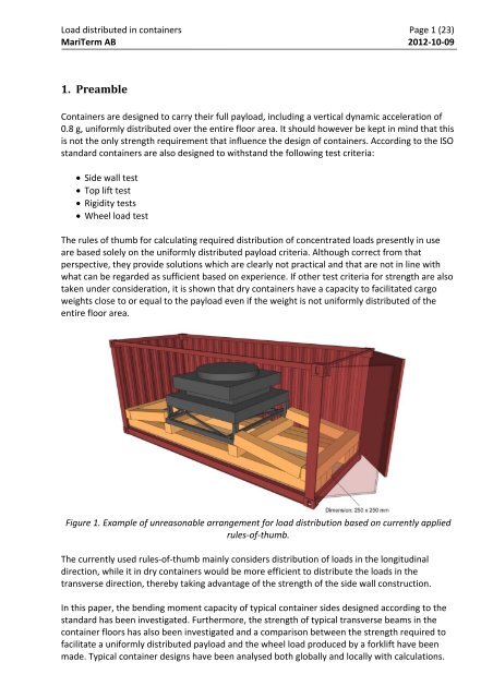
The rules of thumb for calculat<strong>in</strong>g required distribution of concentrated loads presently <strong>in</strong> use<br />
are based solely on the uniformly <strong>distributed</strong> payload criteria. Although correct from that<br />
perspective, they provide solutions which are clearly not practical and that are not <strong>in</strong> l<strong>in</strong>e with<br />
what can be regarded as sufficient based on experience. If other test criteria for strength are also<br />
taken under consideration, it is shown that dry conta<strong>in</strong>ers have a capacity to facilitated cargo<br />
weights close to or equal to the payload even if the weight is not uniformly <strong>distributed</strong> of the<br />
entire floor area.<br />
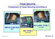
Figure 1. Example of unreasonable arrangement for load distribution based on currently applied<br />
rules‐of‐thumb.<br />
The currently used rules‐of‐thumb ma<strong>in</strong>ly considers distribution of loads <strong>in</strong> the longitud<strong>in</strong>al<br />
direction, while it <strong>in</strong> dry conta<strong>in</strong>ers would be more efficient to distribute the loads <strong>in</strong> the<br />
transverse direction, thereby tak<strong>in</strong>g advantage of the strength of the side wall construction.<br />
In this paper, the bend<strong>in</strong>g moment capacity of typical conta<strong>in</strong>er sides designed accord<strong>in</strong>g to the<br />
standard has been <strong>in</strong>vestigated. Furthermore, the strength of typical transverse beams <strong>in</strong> the<br />
conta<strong>in</strong>er floors has also been <strong>in</strong>vestigated and a comparison between the strength required to<br />
facilitate a uniformly <strong>distributed</strong> payload and the wheel load produced by a forklift have been<br />
made. Typical conta<strong>in</strong>er designs have been analysed both globally and locally with calculations.
<strong>Load</strong> <strong>distributed</strong> <strong>in</strong> conta<strong>in</strong>ers Page 2 (23)<br />
MariTerm AB 2012‐10‐09<br />
2. Global longitud<strong>in</strong>al strength<br />
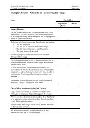
Each side of a conta<strong>in</strong>er can be considered to be a beam with a th<strong>in</strong> web consist<strong>in</strong>g of the<br />
corrugated side wall and top and bottom flanges consist<strong>in</strong>g of profiles designed to stiffen the<br />
construction.<br />
Figure 2a. Typical side structure of an older 20<br />
foot conta<strong>in</strong>er.<br />
Figure 2b. Typical side structure of a modern<br />
40 foot conta<strong>in</strong>er.<br />
The 20 foot conta<strong>in</strong>er above is stiffened by a solid bar of 50 × 12 mm <strong>in</strong> the top. Modern<br />
conta<strong>in</strong>ers are typically stiffened by 60x60x3 mm square profile. Both conta<strong>in</strong>er types are<br />
equipped with a bent profile at the bottom, designed both to stiffen the conta<strong>in</strong>er and to provide<br />
support for the floor<strong>in</strong>g. Examples of typical side structures of 20 and 40 foot conta<strong>in</strong>ers are<br />
found <strong>in</strong> figure 2a and 2b above.
<strong>Load</strong> <strong>distributed</strong> <strong>in</strong> conta<strong>in</strong>ers Page 3 (23)<br />
MariTerm AB 2012‐10‐09<br />
The maximum bend<strong>in</strong>g stress <strong>in</strong> a beam is given by:<br />
� ������� �� ������� ∙<br />
Where:<br />
�<br />
|����|<br />
Mallowed = Allowed bend<strong>in</strong>g moment<br />
�allowed = Allowed stress <strong>in</strong> the material due to bend<strong>in</strong>g<br />
I = Moment of <strong>in</strong>ertia<br />
zmax = Largest distance from the centre of gravity<br />
S<strong>in</strong>ce the test criteria specifies that after the test the conta<strong>in</strong>er shall show no permanent<br />
deflection, the allowed stress is given by the yield stress of the material <strong>in</strong> the critical component.<br />
Both 20 and 40 foot conta<strong>in</strong>ers are typically made of higher grad steel with a yield strength of<br />
350 N/mm 2 and an elastic limit of 345 N/mm 2 . The solid bar <strong>in</strong> the older 20 foot conta<strong>in</strong>er is<br />
however made of normal steel grade with a yield strength of 250 N/mm 2 .<br />
The moment of <strong>in</strong>ertia can be conservatively estimated by the follow<strong>in</strong>g formula:<br />
��� � ∙ ���� ��� � �� � ∙h ��<br />
Where:<br />
�<br />
� �����∙����� �<br />
��<br />
�� ���� ∙� ���� ∙� �����<br />
� �� ��� �<br />
A1 = Area of top flange<br />
A2 = Area of bottom flange<br />
h = Distance between top and bottom flange (Between CGs)<br />
hCG = Distance between bottom flange and Centre of Gravity<br />
hwall = Height of side wall<br />
twall = Thickness of side wall<br />
Due to the thickness of only 1.6 mm, the material <strong>in</strong> the corrugated side wall plate, has been<br />
omitted from calculation of the moment of <strong>in</strong>ertia below.<br />
The moment of <strong>in</strong>ertia as well as the maximum allowed bend<strong>in</strong>g moment for the two side beams<br />
of typical 20 and 40 foot conta<strong>in</strong>ers are calculated <strong>in</strong> the table below:<br />
Parameter / Dimension 20’ conta<strong>in</strong>er 40’ conta<strong>in</strong>er<br />
A1 600 mm 2 684 mm 2<br />
A2 1582 mm 2 1582 mm 2<br />
h 2466 mm 2442 mm<br />
hCG 1054 mm 1054 mm<br />
hwall 2380 mm 2332 mm<br />
twall 0 mm 0 mm<br />
I 2.95 ∙ 10 9 mm 4 3.08 ∙ 10 9 mm 4<br />
zmax 1418 mm 1442 mm<br />
250 N/mm 2<br />
345 N/mm 2<br />
�allowed<br />
Mallowed (for 2 sides) 1.03 ∙ 10 9 Nmm = 105 tonm 1.47 ∙ 10 9 Nmm = 150 tonm
<strong>Load</strong> <strong>distributed</strong> <strong>in</strong> conta<strong>in</strong>ers Page 4 (23)<br />
MariTerm AB 2012‐10‐09<br />
2.1. Maximum po<strong>in</strong>t load<br />
For a simply supported beam, represent<strong>in</strong>g the conta<strong>in</strong>er rest<strong>in</strong>g on its corner fitt<strong>in</strong>gs, subjected<br />
to a po<strong>in</strong>t load W the maximum <strong>in</strong>ner bend<strong>in</strong>g moment can be calculated by the follow<strong>in</strong>g<br />
formula:<br />
� ��� � ����∙�<br />
�<br />
Where:<br />
∙ ���2∙��<br />
fdyn = Factor for tak<strong>in</strong>g account of dynamic variations <strong>in</strong> the vertical load,<br />
fdyn = 1.8<br />
T = Tare weight of conta<strong>in</strong>er<br />
W = Po<strong>in</strong>t load<br />
l = Length of conta<strong>in</strong>er<br />
� ��� � � ��� ∙�<br />
8<br />
∙ ���2∙��<br />
Figure 3. The <strong>in</strong>ner bend<strong>in</strong>g moment for a simply supported beam subjected to a po<strong>in</strong>t load.<br />
Based on this formula and the allowed bend<strong>in</strong>g moments calculated above, the maximum po<strong>in</strong>t<br />
loads <strong>in</strong> the centre of typical conta<strong>in</strong>ers have been calculated for both 20 and 40 foot conta<strong>in</strong>ers,<br />
see table below.<br />
Parameter / Dimension 20’ conta<strong>in</strong>er 40’ conta<strong>in</strong>er<br />
Tare weight, T 2.25 ton 3.75 ton<br />
Length of conta<strong>in</strong>er, l 6.0 m 12.0 m<br />
Mallowed 105 tonm 150 tonm<br />
Maximum po<strong>in</strong>t load 37 ton 27 ton<br />
2.2. Conclusions and recommendations regard<strong>in</strong>g global strength<br />
Due to similar design, the global bend<strong>in</strong>g strength of 20 and 40 foot conta<strong>in</strong>ers are similar. This<br />
<strong>in</strong>dicates that other strength criteria than the uniformly <strong>distributed</strong> payload governs the design<br />
of dry conta<strong>in</strong>er side walls.<br />
Furthermore, it has been shown that short cargoes does not generat<strong>in</strong>g critical bend<strong>in</strong>g moments<br />
neither <strong>in</strong> 20 nor 40 foot conta<strong>in</strong>ers.
<strong>Load</strong> <strong>distributed</strong> <strong>in</strong> conta<strong>in</strong>ers Page 5 (23)<br />
MariTerm AB 2012‐10‐09<br />
3. Local longitud<strong>in</strong>al strength<br />
3.1. Strength of the weld between the bottom beams and the conta<strong>in</strong>er side plate<br />
The conta<strong>in</strong>er sides are typically welded to the base structure with a weld thickness of a = 3 mm.<br />
Figure 4. A fillet weld loaded <strong>in</strong> tension by a force F.<br />
The maximum allowed force Fmax for a fillet weld is given by:<br />
� ��� � �<br />
� ∙� ��<br />
where A is the effective area of the weld, c is the seam factor and fyd is the maximum allowed<br />
stress. The follow<strong>in</strong>g values have been used:<br />
c = 1.2 which is for a fillet weld <strong>in</strong> tension and with a seam class A: weld of ord<strong>in</strong>ary class<br />
fyd = 176 N/mm 2 which is for S235 steel with normal safety class.<br />
The effective area A is the product of weld thickness multiplied by the length of the weld l.<br />
��∑ �∙�<br />
This gives a maximum load F per weld length of<br />
�<br />
�<br />
�<br />
�<br />
� ∙��� � 3<br />
∙ 176 N/mm � 440N/mm � 44 ton/m<br />
1.2<br />
The allowable cargo weight q per meter is calculated by consider<strong>in</strong>g both sides of the conta<strong>in</strong>er<br />
and tak<strong>in</strong>g <strong>in</strong>to account the dynamic variation of forces <strong>in</strong> the vertical direction:<br />
����� � � �<br />
∙ � 48 ���/�<br />
� �.�
<strong>Load</strong> <strong>distributed</strong> <strong>in</strong> conta<strong>in</strong>ers Page 6 (23)<br />
MariTerm AB 2012‐10‐09<br />
3.2. Strength of the side walls<br />
The conta<strong>in</strong>er sides are typically corrugated plate with a m<strong>in</strong>imum thickness of t = 1.6 mm. The<br />
stress <strong>in</strong> a plate loaded <strong>in</strong> tension is the force F divided by the cross section area.<br />
�� �<br />
�∙�<br />
Figure 5. Plate loaded <strong>in</strong> tension.<br />
For a maximum allowed stress of σmax = 345 N/mm 2 this gives a maximum load per unit length of<br />
�<br />
� �� ��� ∙ � � 345 ∙ 1.6 N/mm � 552 N/mm � 56.2 ton/m<br />
The allowable cargo weight per meter q is calculated by consider<strong>in</strong>g both sides of the conta<strong>in</strong>er<br />
and tak<strong>in</strong>g <strong>in</strong>to account the dynamic variation of forces <strong>in</strong> the vertical direction:<br />
����� � � �<br />
∙ � 613 �/�� � 62.5 ���/�<br />
� �.�<br />
From this it is possible to conclude that it is the weld rather than the side plate that limits the<br />
maximum po<strong>in</strong>t load at the conta<strong>in</strong>er side.<br />
The m<strong>in</strong>imum length of concentrated loads due to local strength can thus be calculated as:<br />
�� �<br />
��<br />
Where:<br />
r = M<strong>in</strong>imum length of <strong>distributed</strong> load<br />
P = Weight of cargo
<strong>Load</strong> <strong>distributed</strong> <strong>in</strong> conta<strong>in</strong>ers Page 7 (23)<br />
MariTerm AB 2012‐10‐09<br />
3.3. Required width of transverse beams<br />
If beams, laid on top of the floor<strong>in</strong>g and the side profiles, are used to distribute the load to the<br />
conta<strong>in</strong>er sides, there will be local stresses <strong>in</strong> the side walls. It is reasonable to assume that also<br />
some part of the side wall forward and aft of the contact surface will contribute to carry the load.<br />
A conservative assumption is that the load distribution <strong>in</strong> the side plate will be as shown <strong>in</strong><br />
figure 6, where a is the contact surface from a transversal wooden beam (width of beam).<br />
Figure 6. <strong>Load</strong> distribution <strong>in</strong> the conta<strong>in</strong>er side.<br />
The maximum cargo weight that can be carried by transverse beams laid on top of the floor<strong>in</strong>g<br />
and side profiles of the conta<strong>in</strong>er may then be calculated be the follow<strong>in</strong>g formula:<br />
� ��� � 3∙�∙�∙��3∙48∙�∙��144∙�∙�<br />
Where:<br />
q = Maximum load per meter, q = 48 ton/m<br />
n = Number of beams<br />
a = Width of beams <strong>in</strong> meter<br />
The formula above is valid provided that the longitud<strong>in</strong>al distances between the beams are at<br />
least 2 times their width.
<strong>Load</strong> <strong>distributed</strong> <strong>in</strong> conta<strong>in</strong>ers Page 8 (23)<br />
MariTerm AB 2012‐10‐09<br />
4. Bend<strong>in</strong>g strength of transverse floor<strong>in</strong>g structure<br />
The conta<strong>in</strong>er floor is typically made by plywood which is supported by transverse beams made<br />
of steel, and it can be seen as a stiffened plate. However, as a conservative approach, the<br />
strength of the plywood boards has been disregarded <strong>in</strong> this analysis. The transverse beams are<br />
typically spaced some 280 mm apart <strong>in</strong> the longitud<strong>in</strong>al direction.<br />
There are two strength criteria that the floor<strong>in</strong>g must be able to withstand:<br />
� The payload of the conta<strong>in</strong>er homogeneously <strong>distributed</strong> over the entire floor area, tak<strong>in</strong>g<br />
<strong>in</strong>to account the dynamic load variations <strong>in</strong> the vertical direction dur<strong>in</strong>g sea transport (i.e.<br />
test load<strong>in</strong>g with 2 times the cargo weight).<br />
� Manoeuvr<strong>in</strong>g test with a forklift where the wheels are separated by a distance of 760 mm<br />
and the load on each wheel is 2.73 ton. The pr<strong>in</strong>t area of the wheels is to be no more than<br />
100 x 180 mm.<br />
(It should be noted that most conta<strong>in</strong>ers appears to be tested by us<strong>in</strong>g a forklift with an axle load<br />
of 7.26 tons, see also Second Draft of the Pack<strong>in</strong>g Code, paragraph 7.1.2.5)<br />
The design bend<strong>in</strong>g moment <strong>in</strong> the transverse direction per meter of the conta<strong>in</strong>er floor due to a<br />
homogeneous load can be calculated by the follow<strong>in</strong>g formula:<br />
� ������ � ����∙��∙�<br />
�∙�<br />
Where:<br />
Figure 7. Homogeneously <strong>distributed</strong> load over the conta<strong>in</strong>er floor.<br />
fdyn = Factor for tak<strong>in</strong>g account of dynamic variations <strong>in</strong> the vertical load,<br />
fdyn =2<br />
P0 = Payload<br />
B = Floor width<br />
L = Floor length
<strong>Load</strong> <strong>distributed</strong> <strong>in</strong> conta<strong>in</strong>ers Page 9 (23)<br />
MariTerm AB 2012‐10‐09<br />
Based on this formula the design bend<strong>in</strong>g moment per meter length of the conta<strong>in</strong>er has been<br />
calculated for both 20 and 40 foot conta<strong>in</strong>ers <strong>in</strong> the table below:<br />
Parameter / Dimension 20’ conta<strong>in</strong>er 40’ conta<strong>in</strong>er<br />
Payload, P0 28.0 ton 29.0 ton<br />
Length of conta<strong>in</strong>er, L 6.0 m 12.0 m<br />
Width of conta<strong>in</strong>er, B 2. m 2.3 m<br />
Design bend<strong>in</strong>g moment, mfloor1 2.7 tonm/m 1.4 tonm/m<br />
The design bend<strong>in</strong>g moment <strong>in</strong> the transverse direction per meter of the conta<strong>in</strong>er floor based<br />
on the forklift manoeuvr<strong>in</strong>g test can be calculated by the follow<strong>in</strong>g formula:<br />
Where:<br />
� ������ � ������∙�<br />
� ���������<br />
Figure 8. Two po<strong>in</strong>t loads from the wheels of the forklift.<br />
Pwheel = <strong>Load</strong> on each wheel, Pwheel = 2.73 ton<br />
leffective = Effective length of conta<strong>in</strong>er floor that take up the load from the fork lift<br />
wheels.<br />
This test criterion is identical for both 20 and 40 foot conta<strong>in</strong>ers.<br />
It is reasonable to assume that the plywood floor<strong>in</strong>g is capable of distribut<strong>in</strong>g the load over not<br />
more than 3 <strong>in</strong>dividual floor beams, each loaded with 33% of the load from the cargo. With a<br />
distance between the floor beams of 0.28 m, the follow<strong>in</strong>g design bend<strong>in</strong>g moment per meter of<br />
conta<strong>in</strong>er length can be calculated:<br />
� ������ � �.��∙�.��<br />
� ∙�.��<br />
� 2.5 ����/�<br />
It should be noted that most conta<strong>in</strong>ers are tested with an even heavier forklift (7.26 tons) and<br />
there is some uncerta<strong>in</strong>ty of how the load is spread over the adjacent beams <strong>in</strong> the conta<strong>in</strong>er<br />
floor. It can be concluded that the fork lift test requires a strength <strong>in</strong> the conta<strong>in</strong>er floor that is<br />
very close to that of the uniformly <strong>distributed</strong> load <strong>in</strong> a 20 foot conta<strong>in</strong>er. Given the near identical<br />
construction of floor<strong>in</strong>gs for both 20 and 40 foot conta<strong>in</strong>ers it can be assumed that the same<br />
dimension<strong>in</strong>g moment of 2.7 tonm/m can be used <strong>in</strong> both cases.
<strong>Load</strong> <strong>distributed</strong> <strong>in</strong> conta<strong>in</strong>ers Page 10 (23)<br />
MariTerm AB 2012‐10‐09<br />
5. Bedd<strong>in</strong>g Arrangements<br />
Short or narrow cargoes may overload the floor structure. This may be prevented either by us<strong>in</strong>g<br />
longitud<strong>in</strong>al support beams underneath the cargo to distribute the load over more transverse<br />
floor<strong>in</strong>g beams, or by the use of transverse beams, to distribute the load towards the strong side<br />
structures of the conta<strong>in</strong>er.<br />
Different models for estimat<strong>in</strong>g the stress <strong>in</strong> the wooden support beams and their required<br />
bend<strong>in</strong>g strength have been proposed. If the wooden beams are to carry the full load of the<br />
cargo by themselves, a both‐ends‐suspended beam rest<strong>in</strong>g only on its ends can be used, see<br />
below.<br />
Rigid cargo Flexible cargo<br />
<strong>Load</strong><strong>in</strong>g of both‐ends‐suspended beams carry<strong>in</strong>g the weight of the cargo without help from the<br />
floor.<br />
It is however not likely that the wooden beams are so stiff that they don’t get contact with the<br />
floor beneath them and support at other po<strong>in</strong>ts than the ends. Furthermore, the purpose of the<br />
beam is rather to supplement the strength of the floor and spread the load of the cargo over a<br />
wider are. Optimally, the wooden beams would spread the footpr<strong>in</strong>t of the cargo evenly over the<br />
entire floor area underneath it, as illustrated <strong>in</strong> the figure below.<br />
Rigid cargo Flexible cargo<br />
<strong>Load</strong><strong>in</strong>g of beams which distribute the cargo weight evenly over their entire length.<br />
The model above is suitable for flexible cargo, but due to the relative flexibility of wood<br />
compared to steel, the wooden beams have a limited capacity to spread the load over a great<br />
length when subjected to the po<strong>in</strong>t loads result<strong>in</strong>g from rigid cargo.
<strong>Load</strong> <strong>distributed</strong> <strong>in</strong> conta<strong>in</strong>ers Page 11 (23)<br />
MariTerm AB 2012‐10‐09<br />
Deflection of beam with rigid cargo, supported by uniformly <strong>distributed</strong> load from underneath.<br />
The red l<strong>in</strong>e <strong>in</strong> the illustration above shows the deflection of the beam. As can be seen for the<br />
rigid cargo case, the beam would deflect upwards at the centre if subjected to a uniformly<br />
<strong>distributed</strong> load from below, at least for wide rigid cargoes. This means that there would be little<br />
pressure between the wooden beam and the floor at the centre and at the ends. Thus, a more<br />
realistic model for rigid cargoes is given below:<br />
Deflection of beam with rigid cargo, supported by variably <strong>distributed</strong> load based on the contact<br />
pressure between the wooden beam and the conta<strong>in</strong>er floor. The contact pressure is based on the<br />
deflection of the wooden beam and the conta<strong>in</strong>er floor.<br />
The above realistic model takes care of the fact that wooden beams deflect more than the steel<br />
beams of a conta<strong>in</strong>er floor. However, as this model is too complex to base any regulations on, it<br />
is suggested to use a simplified model where the contact force is uniformly <strong>distributed</strong> but<br />
concentrated around the support po<strong>in</strong>ts of the cargo:<br />
Simplified model with the load concentrated around the support po<strong>in</strong>ts of the cargo.
<strong>Load</strong> <strong>distributed</strong> <strong>in</strong> conta<strong>in</strong>ers Page 12 (23)<br />
MariTerm AB 2012‐10‐09<br />
5.1. Required length of longitud<strong>in</strong>al support beams for narrow cargoes<br />
Cargoes with smaller width than the <strong>in</strong>ner width of the conta<strong>in</strong>er may be supported from<br />
underneath by longitud<strong>in</strong>al beams <strong>in</strong> order not to overload the transverse floor beams. By this,<br />
the weight of the cargo is <strong>distributed</strong> to a greater number of floor beams.<br />
Then this method is used, the beams should be placed at the sides of the cargo, thereby load<strong>in</strong>g<br />
the transvers beams as close as possible to the side of the conta<strong>in</strong>er.<br />
Figure 10. Narrow cargo placed on longitud<strong>in</strong>al support beams.<br />
If the cargo is rest<strong>in</strong>g on 2 beams placed underneath the outermost parts of the cargo, the<br />
transverse beams <strong>in</strong> the conta<strong>in</strong>er floor are subjected to 2 po<strong>in</strong>t loads and the result<strong>in</strong>g bend<strong>in</strong>g<br />
moment <strong>in</strong> the floor structure <strong>in</strong> the transverse direction can be calculated by the follow<strong>in</strong>g<br />
formula:<br />
�� ����∙�<br />
�<br />
Where:<br />
∙ �����<br />
fdyn = Factor for tak<strong>in</strong>g account of dynamic variations <strong>in</strong> the vertical load,<br />
fdyn =1.8<br />
P = Cargo weight<br />
B = Floor width<br />
s = Distance between longitud<strong>in</strong>al support beams<br />
This bend<strong>in</strong>g moment should be less or equal to the design bend<strong>in</strong>g moment of the floor<br />
structure:<br />
�� ����∙�<br />
�<br />
∙ ����� �� ����� ∙�
<strong>Load</strong> <strong>distributed</strong> <strong>in</strong> conta<strong>in</strong>ers Page 13 (23)<br />
MariTerm AB 2012‐10‐09<br />
Where:<br />
mfloor = 2.7 tonm/m<br />
r = Length of longitud<strong>in</strong>al support beams [m]<br />
The required length of longitud<strong>in</strong>al support beams can thus be calculated as (with the weight <strong>in</strong><br />
ton and the lengths <strong>in</strong> meters):<br />
�� ����∙�<br />
� ∙ � �����<br />
∙ ����� � �.�∙�<br />
∙ ����� �0.17∙�∙�����<br />
� ∙�.�<br />
By proposal of Hermann Kaps the required section modulus of the support beams (calculated as a<br />
both‐end‐suspended beam) is given by:<br />
��<br />
��� ∙�∙���������������<br />
�∙�<br />
Where:<br />
W = Section modulus of beams [cm 3 ]<br />
rcargo = Length of cargo [m]<br />
n = Number of support beams<br />
σ = Permissible bend<strong>in</strong>g stress <strong>in</strong> beam [kN/cm 2 ]<br />
Alternatively the required section modulus for the support beams (if considered to be uniformly<br />
supported from underneath over the entire length) could be calculated by:<br />
�� 9.81 ∙ 1000 ∙ ���� ∙�<br />
8∙������ ∙�������� ∙� ������� �������� � �<br />
� 221 ∙<br />
�������� ∙� ∙ ������� �������� �<br />
������ Where:<br />
W = Section modulus of support beams [cm 3 ]<br />
n = Number of support beams<br />
P = Cargo weight, [ton]<br />
fdyn = Factor for tak<strong>in</strong>g account of dynamic variations <strong>in</strong> the vertical load,<br />
fdyn =1.8<br />
rbeams = Length of support beams, [m]<br />
rcargo = Length of cargo, [m]<br />
σallowed = Allowed stress <strong>in</strong> <strong>in</strong> support beams, [kN/cm 2 ]<br />
For wood: �allowed =2.4 kN/cm 2<br />
For steel: �allowed =18 kN/cm 2
<strong>Load</strong> <strong>distributed</strong> <strong>in</strong> conta<strong>in</strong>ers Page 14 (23)<br />
MariTerm AB 2012‐10‐09<br />
Example<br />
Two coils are to be loaded on longitud<strong>in</strong>al wooden support beams <strong>in</strong> a 20‐foot conta<strong>in</strong>er. The<br />
coils are 1.3m wide, has got a diameter of 1.3m and weigh 10 tons each. Assume that the coils<br />
rest on wedges separated by a distance of 0.9m <strong>in</strong> the longitud<strong>in</strong>al direction.<br />
Figure 11. Coils loaded on longitud<strong>in</strong>al support beams.<br />
The m<strong>in</strong>imum length of the beams is given by<br />
� ���� �0.17∙�∙����� � 0.17 ∙ 10 ∙ �2.3 � 1.3� �1.7�<br />
The required section modulus of these beams becomes<br />
��<br />
��� ∙�∙���������������<br />
�∙�<br />
� ���∙��∙��.���.��<br />
�∙�.�<br />
Alternatively, the section modulus becomes:<br />
� � 221 ∙<br />
�<br />
��������∙�<br />
∙ ��������������� �<br />
������<br />
� 205 �� �<br />
� 221 ∙ �� ��.���.���<br />
∙ � 164 ���<br />
�∙�.� �.�<br />
Beams with a dimensions of 4’’ × 5’’ (10 cm × 12.5 cm) have a section modulus of W = 208 cm 3 ).
<strong>Load</strong> <strong>distributed</strong> <strong>in</strong> conta<strong>in</strong>ers Page 15 (23)<br />
MariTerm AB 2012‐10‐09<br />
5.2. Required bend<strong>in</strong>g strength of transverse support beams<br />
If narrow cargoes are <strong>in</strong>stead placed on transverse support beams with a length equal to the<br />
<strong>in</strong>ner width of the conta<strong>in</strong>er, both the beams and the floor<strong>in</strong>g structure will help support the<br />
cargo.<br />
Figure 12. Narrow cargo placed on transverse support beams with a width equal to the <strong>in</strong>ner<br />
width of the conta<strong>in</strong>er.<br />
Even though weight of the cargo might not be fully <strong>distributed</strong> to the whole length of the<br />
wooden beam, it is none the less recommended that they <strong>in</strong> all cases stretch over the entire<br />
width of the conta<strong>in</strong>er.<br />
Rigid cargoes<br />
The bend<strong>in</strong>g moment <strong>in</strong> the wooden beams and the floor beams due to the load from a rigid<br />
cargo and the <strong>distributed</strong> load between the two elements are illustrated below.
<strong>Load</strong> <strong>distributed</strong> <strong>in</strong> conta<strong>in</strong>ers Page 16 (23)<br />
MariTerm AB 2012‐10‐09<br />
The bend<strong>in</strong>g moment <strong>in</strong> the floor beam can be calculated accord<strong>in</strong>g to the follow<strong>in</strong>g formula:<br />
With:<br />
�� � �<br />
∙ ��∙�2� � �� ��∙�2� � ���<br />
�<br />
���� �<br />
∙ �����<br />
�<br />
���� �<br />
∙ �����<br />
�<br />
�� ����∙�<br />
�<br />
� ∙�∙�����<br />
the moment can be calculated as:<br />
� � � ����∙�∙�����<br />
��<br />
∙ �8���<br />
The moment <strong>in</strong> the floor beam should as a maximum equal the allowable moment derived <strong>in</strong><br />
Chapter 4. In parallel with the forklift test criteria this effective length can be estimated by<br />
assum<strong>in</strong>g that each transverse wooden beam distributes the load over three floor beams, which<br />
are spaced 0.28 m apart.<br />
� � � ����∙�∙�����<br />
��<br />
∙ �8��� �� ����� ∙� ���������<br />
Where:<br />
n = Number of transverse support beams<br />
fdyn = Factor for tak<strong>in</strong>g account of dynamic variations <strong>in</strong> the vertical load,<br />
fdyn =1.8<br />
P = Cargo weight [m]<br />
B = Floor width [m]<br />
s = Width of cargo [m]<br />
mfloor = Strength of the conta<strong>in</strong>er floor, 2.7 tonm/m<br />
leffective = Contribut<strong>in</strong>g length of conta<strong>in</strong>er floor [m], taken as m<strong>in</strong>imum of<br />
Beams spaced more than 0.84 m apart: leffective = 3 ∙ � ∙ 0.28<br />
Beams spaced less than 0.84 m apart: leffective = � � 0.56<br />
r = Length of cargo [m]<br />
leffective is the length of conta<strong>in</strong>er floor that the wooden beams are able to distribute the load from<br />
the cargo to. In parallel with the forklift test criteria this effective length can be estimated by<br />
assum<strong>in</strong>g that each transverse wooden beam distributes the load over three floor beams, which<br />
are spaced 0.28 m apart. Alternatively, if the wooden beams are spaced closer than 3 x 0.28<br />
=0.84 meters apart, the effective length should be taken as the length of the cargo plus 2 x 0.28 =<br />
0.56 m.
<strong>Load</strong> <strong>distributed</strong> <strong>in</strong> conta<strong>in</strong>ers Page 17 (23)<br />
MariTerm AB 2012‐10‐09<br />
The factor x, which <strong>in</strong>dicates how wide the wooden beams have to be able to distribute the load,<br />
can be calculated as:<br />
��8� � �����∙� ���������∙��<br />
����∙�∙�����<br />
The bend<strong>in</strong>g moment <strong>in</strong> the centre of the wooden beam can be calculated as:<br />
� � � ����∙�<br />
�<br />
∙� � ��� �<br />
� �<br />
� � � ������∙�∙�∙�����<br />
��<br />
Thus, the required section modulus of the wooden support beams for a rigid cargo can be<br />
calculated as:<br />
�� ����∙�∙�∙�����<br />
��∙�∙��������<br />
� ����∙�∙�������∙� �����∙� ���������<br />
�∙�∙��������<br />
With lengths <strong>in</strong> meters and weights <strong>in</strong> ton and with the material strength to be <strong>in</strong>serted <strong>in</strong><br />
kN/cm 2 , the bend<strong>in</strong>g strength becomes:<br />
�� ���∙����∙�∙��.���������∙� ���������<br />
�∙��������<br />
Where:<br />
W = Bend<strong>in</strong>g strength [cm 3 ]<br />
n = Number of support beams<br />
P = Cargo weight, [ton]<br />
s = Cargo width, [m]<br />
σallowed = Allowed stress <strong>in</strong> the material due to bend<strong>in</strong>g, [kN/cm 2 ]<br />
For wood: �allowed =2.4 kN/cm 2<br />
For steel: �allowed =18 kN/cm 2<br />
Furthermore, <strong>in</strong> order to satisfy the local strength of the side walls, see chapter 3.3, the m<strong>in</strong>imum<br />
width of the transverse beams should be calculated from the follow<strong>in</strong>g formula:<br />
�� � � �<br />
� �<br />
�∙�∙� �∙��.�∙� ���∙�<br />
Where:<br />
a = Width of beams, [m]<br />
P = Cargo weight, [ton]<br />
q = Maximum load per meter, q = 63.4 ton/m<br />
n = Number of beams<br />
The gap between the beams should be at least 2 times their width.
<strong>Load</strong> <strong>distributed</strong> <strong>in</strong> conta<strong>in</strong>ers Page 18 (23)<br />
MariTerm AB 2012‐10‐09<br />
Flexible cargoes<br />
The bend<strong>in</strong>g moment <strong>in</strong> the wooden beams and the floor beams due to the load from a flexible<br />
cargo and the <strong>distributed</strong> load between the two elements are illustrated below.<br />
The bend<strong>in</strong>g moment <strong>in</strong> the floor beam can be calculated accord<strong>in</strong>g to the follow<strong>in</strong>g formula:<br />
� � � ����∙�<br />
�<br />
∙ �2� � ���<br />
The moment <strong>in</strong> the floor beam should as a maximum equal the allowable moment derived <strong>in</strong><br />
Chapter 4. In parallel with the forklift test criteria this effective length can be estimated by<br />
assum<strong>in</strong>g that each transverse wooden beam distributes the load over three floor beams, which<br />
are spaced 0.28 m apart.<br />
� � � ����∙�<br />
�<br />
∙ �2� � ��� �� ����� ∙� ���������<br />
Where:<br />
n = Number of transverse support beams<br />
fdyn = Factor for tak<strong>in</strong>g account of dynamic variations <strong>in</strong> the vertical load,<br />
fdyn =1.8<br />
P = Cargo weight [m]<br />
B = Floor width [m]<br />
s = Width of cargo [m]<br />
mfloor = Strength of the conta<strong>in</strong>er floor, 2.7 tonm/m<br />
leffective = Contribut<strong>in</strong>g length of conta<strong>in</strong>er floor [m], taken as m<strong>in</strong>imum of<br />
Beams spaced more than 0.84 m apart: leffective = 3 ∙ � ∙ 0.28<br />
Beams spaced less than 0.84 m apart: leffective = � � 0.56<br />
r = Length of cargo [m]<br />
leffective is the length of conta<strong>in</strong>er floor that the wooden beams are able to distribute the load from<br />
the cargo to. In parallel with the forklift test criteria this effective length can be estimated by<br />
assum<strong>in</strong>g that each transverse wooden beam distributes the load over three floor beams, which<br />
are spaced 0.28 m apart. Alternatively, if the wooden beams are spaced closer than 3 x 0.28
<strong>Load</strong> <strong>distributed</strong> <strong>in</strong> conta<strong>in</strong>ers Page 19 (23)<br />
MariTerm AB 2012‐10‐09<br />
=0.84 meters apart, the effective length should be taken as the length of the cargo plus 2 x 0.28 =<br />
0.56 m.<br />
The factor x, which <strong>in</strong>dicates how wide the wooden beams have to be able to distribute the load,<br />
can be calculated as:<br />
�� �<br />
� ∙�2��� �����∙����������∙� ����∙�<br />
�<br />
The bend<strong>in</strong>g moment <strong>in</strong> the centre of the wooden beam can be calculated as:<br />
� � � ����∙�<br />
�<br />
∙� �∙�<br />
�<br />
�<br />
�<br />
� ������∙�∙� ∙ �� �1�<br />
�<br />
The required section modulus of the wooden support beams for a rigid cargo can be calculated<br />
as:<br />
�� ����∙�∙�<br />
∙ �� �1�� �∙�∙��������<br />
����∙�∙��∙������∙������∙���������� �∙�∙��������<br />
With lengths <strong>in</strong> meters and weights <strong>in</strong> ton and with the material strength to be <strong>in</strong>serted <strong>in</strong><br />
kN/cm 2 , the bend<strong>in</strong>g strength becomes:<br />
�� ���∙����∙�∙��.���������∙� ���������<br />
�∙��������<br />
Where:<br />
W = Bend<strong>in</strong>g strength [cm 3 ]<br />
n = Number of support beams<br />
P = Cargo weight, [ton]<br />
s = Cargo width, [m]<br />
σallowed = Allowed stress <strong>in</strong> the material due to bend<strong>in</strong>g, [kN/cm 2 ]<br />
For wood: �allowed =2.4 kN/cm 2<br />
For steel: �allowed =18 kN/cm 2<br />
Furthermore, <strong>in</strong> order to satisfy the local strength of the side walls, see chapter 3.3, the m<strong>in</strong>imum<br />
width of the transverse beams should be calculated from the follow<strong>in</strong>g formula:<br />
�� � � �<br />
� �<br />
�∙�∙� �∙��.�∙� ���∙�<br />
Where:<br />
a = Width of beams, [m]<br />
P = Cargo weight, [ton]<br />
q = Maximum load per meter, q = 63.4 ton/m<br />
n = Number of beams<br />
The gap between the beams should be at least 2 times their width.
<strong>Load</strong> <strong>distributed</strong> <strong>in</strong> conta<strong>in</strong>ers Page 20 (23)<br />
MariTerm AB 2012‐10‐09<br />
Example<br />
Steel rods are to be loaded on transverse wooden beams <strong>in</strong> a 20‐foot conta<strong>in</strong>er. The payload is,<br />
P = 20 ton and the width of the cargo, s = 2 m. The steel rods are rest<strong>in</strong>g on 5 beams.<br />
Figure 14. Steel rods loaded on transverse support beams.<br />
The effective length of the 5 beams becomes:<br />
l ��������� �3∙�∙0.28�3∙5∙0.28�4.2�<br />
The required section modulus for the support beams becomes,<br />
�� ���∙����∙�∙��.���������∙� ���������<br />
�∙��������<br />
� ���∙�.�∙��∙��.���������∙�.�<br />
�∙�.�<br />
� 79 �� �<br />
which correspond to beams with a dimensions of 3’’×4’’ (7.5 cm × 10 cm, W = 94 cm 3 )
<strong>Load</strong> <strong>distributed</strong> <strong>in</strong> conta<strong>in</strong>ers Page 21 (23)<br />
MariTerm AB 2012‐10‐09<br />
6. Conclusions<br />
It has been found that the sides of a conta<strong>in</strong>er can take up much larger bend<strong>in</strong>g moments than<br />
what is created by the payload if it is uniformly <strong>distributed</strong> and thus the technique to distribute<br />
concentrated loads <strong>in</strong> a dry conta<strong>in</strong>er, designed accord<strong>in</strong>g to the standard, should be to transfer<br />
the load to the sides rather than spread<strong>in</strong>g it out <strong>in</strong> longitud<strong>in</strong>al direction.<br />
When nom<strong>in</strong>at<strong>in</strong>g the m<strong>in</strong>imum length of concentrated cargoes, the global strength, i.e. bend<strong>in</strong>g<br />
of the whole conta<strong>in</strong>er rest<strong>in</strong>g on its corner fitt<strong>in</strong>gs, need not be considered for all practical<br />
applications. Only the local strength, i.e. tension <strong>in</strong> the side walls, should be considered.<br />
Concentrated cargo weights with lesser width than the conta<strong>in</strong>er should be supported either by<br />
longitud<strong>in</strong>al support beams, thereby transferr<strong>in</strong>g the load to a greater part of the floor<strong>in</strong>g<br />
structure, or by transverse support beams which transfers the loads to the side structure of the<br />
conta<strong>in</strong>er. The latter is to be regarded as the preferred method.<br />
Regard<strong>in</strong>g the capability of the floor<strong>in</strong>g to distribute forces <strong>in</strong> the transverse direction, it has been<br />
found that the real strength required by the wheel load test is larger than what the uniformly<br />
<strong>distributed</strong> payload requires for typical conta<strong>in</strong>ers, especially for 40 foot conta<strong>in</strong>ers. Due to<br />
nearly identical design, the same ability to resist bend<strong>in</strong>g can be assumed for both 20 and 40 foot<br />
conta<strong>in</strong>ers when design<strong>in</strong>g the required support under the load to distribute it to the conta<strong>in</strong>er<br />
sides.
<strong>Load</strong> <strong>distributed</strong> <strong>in</strong> conta<strong>in</strong>ers Page 22 (23)<br />
MariTerm AB 2012‐10‐09<br />
7. Recommendations<br />
7.1. M<strong>in</strong>imum length of longitud<strong>in</strong>al support beams for narrow cargoes<br />
The required length of longitud<strong>in</strong>al support beams for narrow cargoes can thus be calculated as:<br />
� � 0.17 ∙ � ∙ �����<br />
Where:<br />
rbeams = Length of support beams [m]<br />
P = Cargo weight [ton]<br />
B = Floor width [m]<br />
s = Distance between longitud<strong>in</strong>al support beams [m]<br />
By proposal of Hermann Kaps the required section modulus of the support beams is given by<br />
��<br />
��� ∙�∙���������������<br />
�∙�<br />
Where:<br />
W = Section modulus of beams [cm 3 ]<br />
rcargo = Length of cargo [m]<br />
n = Number of support beams<br />
σ = Permissible bend<strong>in</strong>g stress <strong>in</strong> beam [kN/cm 2 ]<br />
Alternatively the required section modulus for the support beams could be calculated by<br />
� � 221 ∙<br />
�<br />
��������∙�<br />
∙ ��������������� �<br />
������<br />
Where:<br />
W = Section modulus of support beams [cm 3 ]<br />
n = Number of support beams<br />
P = Cargo weight, [ton]<br />
fdyn = Factor for tak<strong>in</strong>g account of dynamic variations <strong>in</strong> the vertical load,<br />
fdyn =1.8<br />
rbeams = Length of support beams, [m]<br />
rcargo = Length of cargo, [m]<br />
σallowed = Allowed stress <strong>in</strong> <strong>in</strong> support beams, [kN/cm 2 ]<br />
For wood: �allowed =2.4 kN/cm 2<br />
For steel: �allowed =18 kN/cm 2
<strong>Load</strong> <strong>distributed</strong> <strong>in</strong> conta<strong>in</strong>ers Page 23 (23)<br />
MariTerm AB 2012‐10‐09<br />
7.2. Required bend<strong>in</strong>g strength of transverse support beams<br />
It is suggested that the required section modulus for load bear<strong>in</strong>g transverse support beam is<br />
calculated by the follow<strong>in</strong>g formulae:<br />
Rigid cargo: �� ���∙����∙�∙��.���������∙� ���������<br />
�∙��������<br />
Flexible cargo: �� ���∙����∙�∙��.���������∙� ���������<br />
�∙��������<br />
Where:<br />
W = Section modulus of support beams [cm 3 ]<br />
n = Number of support beams<br />
P = Cargo weight, [ton]<br />
s = Cargo width, [m]<br />
σallowed = Allowed stress <strong>in</strong> <strong>in</strong> support beams, [kN/cm 2 ]<br />
For wood: �allowed =2.4 kN/cm 2<br />
For steel: �allowed =18 kN/cm 2<br />
leffective = Contribut<strong>in</strong>g length of conta<strong>in</strong>er floor [m], taken as m<strong>in</strong>imum of<br />
Beams spaced more than 0.84 m apart: leffective = 3 ∙ � ∙ 0.28<br />
Beams spaced less than 0.84 m apart: leffective = � � 0.56<br />
In order to satisfy the local strength of the side walls, the m<strong>in</strong>imum width of the transverse<br />
beams should be calculated from the follow<strong>in</strong>g formula:<br />
�� �<br />
���∙�<br />
Where:<br />
P = Cargo weight [ton]<br />
n = number of beams<br />
a = width of beams [m]<br />
The gap between the beams should be at least 2 times their width.