
Create successful ePaper yourself
Turn your PDF publications into a flip-book with our unique Google optimized e-Paper software.
iom<strong>as</strong>s design best practice<br />
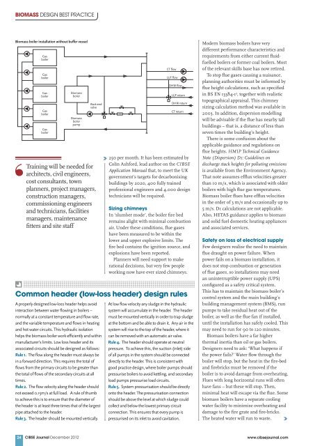
Biom<strong>as</strong>s boiler installation without buffer vessel<br />
24<br />
G<strong>as</strong><br />
boiler<br />
G<strong>as</strong><br />
boiler<br />
G<strong>as</strong><br />
boiler<br />
G<strong>as</strong><br />
boiler<br />
G<strong>as</strong><br />
boiler<br />
Biom<strong>as</strong>s<br />
boiler<br />
Biom<strong>as</strong>s<br />
boiler<br />
pump<br />
Back-end<br />
valve<br />
Training will be needed for<br />
architects, civil engineers,<br />
cost consultants, town<br />
planners, project managers,<br />
construction managers,<br />
commissioning engineers<br />
and technicians, facilities<br />
managers, maintenance<br />
fitters and site staff<br />
A properly designed low-loss header helps avoid<br />
interaction between water flowing in boilers –<br />
normally at a constant temperature and flow rate,<br />
and the variable temperature and flows in heating<br />
and hot water circuits. This hydraulic isolation<br />
helps the biom<strong>as</strong>s boiler work efficiently and within<br />
manufacturer’s limits. Low loss header and its<br />
<strong>as</strong>sociated circuits should be designed <strong>as</strong> follows:<br />
Rule 1. The flow along the header must always be<br />
in a forward direction. This requires the total of<br />
flows from the primary circuits to be greater than<br />
the total of flows of the secondary circuits at all<br />
times.<br />
Rule 2. The flow velocity along the header should<br />
not exceed 0.15m/s at full load. A rule of thumb<br />
to achieve this is to ensure that the diameter of<br />
the header is at le<strong>as</strong>t three times that of the largest<br />
pipe attached to the header.<br />
Rule 3. The header should be mounted vertically.<br />
250 per month. It h<strong>as</strong> been estimated by<br />
Colin Ashford, lead author on the <strong>CIBSE</strong><br />
Application Manual that, to meet the UK<br />
government’s targets for decarbonising<br />
buildings by 2020, 400 fully trained<br />
professional engineers and 4,000 design<br />
technicians will be required.<br />
Sizing chimneys<br />
In ‘slumber mode’, the boiler fire bed<br />
remains alight with minimal combustion<br />
air. Under these conditions, flue g<strong>as</strong>es<br />
have been me<strong>as</strong>ured to be within the<br />
lower and upper explosive limits. The<br />
fire bed contains the ignition source, and<br />
explosions have been reported.<br />
Planners will need support to make<br />
rational decisions, but very few people<br />
working now have ever sized chimneys.<br />
Common header (low-loss header) design rules<br />
HM<br />
At low flow velocity any sludge in the hydraulic<br />
system will accumulate in the header. The header<br />
must be mounted vertically in order to trap sludge<br />
at the bottom and be able to drain it. Any air in the<br />
system will rise to the top of the header, where it<br />
can be removed with an automatic air valve.<br />
Rule 4. The header should operate at neutral<br />
pressure. To achieve this, the suction (inlet) side<br />
of all pumps in the system should be connected<br />
directly to the header. This is consistent with<br />
good practice design, where boiler pumps should<br />
pressurise boilers to avoid kettling, and secondary<br />
load pumps pressurise load circuits.<br />
Rule 5. System pressurisation should be directly<br />
onto the header. The pressurisation connection<br />
should be above the level at which sludge could<br />
collect and below the lowest primary circuit<br />
connection. This ensures that every pump is<br />
pressurised on its inlet to avoid cavitation.<br />
Modern biom<strong>as</strong>s boilers have very<br />
different performance characteristics and<br />
requirements from either current fluidfuelled<br />
boilers or former coal boilers. Most<br />
of the relevant skills b<strong>as</strong>e h<strong>as</strong> now retired.<br />
To stop flue g<strong>as</strong>es causing a nuisance,<br />
planning authorities must be informed by<br />
flue height calculations, such <strong>as</strong> specified<br />
in BS EN 13384-1 3 , together with realistic<br />
topographical appraisal. This chimney<br />
sizing calculation method w<strong>as</strong> available in<br />
2003. In addition, dispersion modelling<br />
will be advisable if the flue h<strong>as</strong> nearby tall<br />
buildings – that is, a distance of less than<br />
seven times the building’s height.<br />
There is some confusion about the<br />
applicable guidance and regulations on<br />
flue heights. HMIP Technical Guidance<br />
Note (Dispersion) D1: Guidelines on<br />
discharge stack heights for polluting emissions<br />
is available from the Environment Agency.<br />
That note <strong>as</strong>sumes efflux velocities greater<br />
than 10 m/s, which is <strong>as</strong>sociated with older<br />
boilers with high flue g<strong>as</strong> temperatures.<br />
Biom<strong>as</strong>s boiler flues have efflux velocities<br />
in the order of 3 m/s and occ<strong>as</strong>ionally up to<br />
5 m/s. D1 calculations are not applicable.<br />
Also, HETAS guidance applies to biom<strong>as</strong>s<br />
and solid fuel domestic heating appliances<br />
and <strong>as</strong>sociated services.<br />
Safety on loss of electrical supply<br />
Few designers realise the need to maintain<br />
flue draught on power failure. When<br />
power fails on a biom<strong>as</strong>s installation, it<br />
does not stop combustion or generation<br />
of flue g<strong>as</strong>es, so installations may need<br />
an uninterruptible power supply (UPS)<br />
configured <strong>as</strong> a safety critical system.<br />
This h<strong>as</strong> to maintain the biom<strong>as</strong>s boiler’s<br />
control system and the main building’s<br />
building management system (BMS), run<br />
pumps to take residual heat out of the<br />
boiler, <strong>as</strong> well <strong>as</strong> the flue fan if installed,<br />
until the installation h<strong>as</strong> safely cooled. This<br />
may need to run for 90 to 120 minutes.<br />
Biom<strong>as</strong>s boilers have a far higher<br />
thermal inertia than oil or g<strong>as</strong> boilers.<br />
Designers need to <strong>as</strong>k: ‘What happens if<br />
the power fails?’ Water flow through the<br />
boiler will stop, but the heat in the fire-bed<br />
and firebricks must be removed if the<br />
boiler is to avoid damage from overheating.<br />
Flues with long horizontal runs will often<br />
have fans – but these will stop. Then,<br />
minimal heat will escape via the flue. Some<br />
biom<strong>as</strong>s boilers have a separate cooling<br />
water facility to minimise overheating and<br />
damage to the fire grate and fire-bricks.<br />
The heated water will run to w<strong>as</strong>te.<br />
<strong>CIBSE</strong> <strong>Journal</strong> December 2012 www.cibsejournal.com<br />
CT flow<br />
U/F flow<br />
DHW flow<br />
U/F return<br />
DHW return<br />
CT return