DNFT-LED - Whitlock Instruments
DNFT-LED - Whitlock Instruments
DNFT-LED - Whitlock Instruments

You also want an ePaper? Increase the reach of your titles
YUMPU automatically turns print PDFs into web optimized ePapers that Google loves.
<strong>DNFT</strong> <strong>DNFT</strong>R<br />
DIGITAL NO-FLOW TIMER<br />
U.S. PAT. NO. 5,835,372<br />
Distributed by:<br />
U.S. PAT. NO. 5,835,372<br />
R<br />
DIGITAL NO-FLOW TIMER<br />
CYCLE INDICATION<br />
Factory Sealed<br />
CE<br />
R II 2G EEx md IIC T5<br />
C US Cl I; Zone 1; Ex md IIC T4<br />
186200<br />
Cl I; Div 1; Grps. A,B,C,D;T4<br />
0344<br />
KEMA 00ATEX1090 X Amb. -40° C...+80°C<br />
<strong>DNFT</strong>-<strong>LED</strong><br />
MODEL<br />
RATED<br />
SERIAL #<br />
P/N<br />
ALARM<br />
INS INSTRU INSTRUMENT TRUMEN MENT<br />
ODESSA, TX USA<br />
<strong>LED</strong><br />
2. 2.5V 2.5VA 5VA A / 240 240VDC 40VD VDC C<br />
00 05 06<br />
2-M IN<br />
RED-Open Loop ORANGE-Closed Loop GRN-Ground<br />
1-800-337-3412<br />
1-800-337-3412<br />
WHITLOCK<br />
WH WHITL ITLOC OCK K<br />
MONITORS MOVEMENT OF DIVIDER<br />
BLOCK PISTON FOR DEPENDABLE<br />
“TIMED” SHUTDOWN PROTECTION<br />
CLOSED LOOP OR OPEN LOOP<br />
OPERATION<br />
INSTALLS DIRECTLY TO DIVIDER<br />
VALVE<br />
NOT AFFECTED BY TEMPERATURE<br />
OR OIL VISCOSITY<br />
REQUIRES NO EXTERNAL POWER<br />
<strong>LED</strong> INDICATOR - CYCLE INDICATION<br />
DEDICATED SWITCH CLOSURE TO<br />
MONITOR EACH DIVIDER VALVE<br />
CYCLE (PS OPTION)<br />
FIELD REPLACEABLE BATTERY<br />
WHITLOCK INSTRUMENT<br />
1300 N. Texas<br />
Odessa, TX 79761<br />
432.3373412 Fax 432.335.5926<br />
1.800.337.3412 www.noflo.com<br />
<strong>DNFT</strong>-<strong>LED</strong><br />
P/N: 000506<br />
wwwww..nofflo..com<br />
www.noflo.com<br />
SPECIFICATIONS<br />
WHIT WHITLOCK ITLOCK<br />
IN INSTRUMENT<br />
ODESSA, TX USA<br />
506LIT <strong>LED</strong>-WI-1<br />
07.11.01<br />
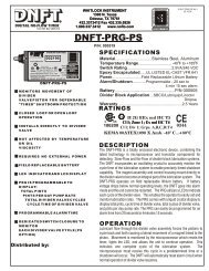
Material..................................................Stainless Steel, Aluminum<br />
0 0<br />
Temperature Range.............................................. -40 F to +185 F<br />
Switch RaTing........................................................2.5VA/240 VDC<br />
Epoxy Encapsulated.......................UL LISTED EL-CAST VFR 641<br />
Alarm/Shutdown........................ Factory default for 2 minute alarm<br />
Power......................................Field Replaceable - Lithium Battery<br />
Battery........................................................................ P/N 000505<br />
Alternate Battery........................................Radio Shack 960-0418<br />
Divider Block Application............Dropsa/Lincoln/SBCO/Lubriquip<br />
Warranty.........................................................................2.5 Years<br />
RATINGS<br />
R II 2G EEx md IIC T5<br />
C US<br />
186200<br />
Cl I; Zone 1; Ex md IIC T4<br />
Cl I; Div 1; Grps. A,B,C,D;T4<br />
0344<br />
KEMA 00ATEX1090 X Amb. -40° C...+80°C<br />
DESCRIPTION<br />
The <strong>DNFT</strong>-<strong>LED</strong> is a totally enclosed electronic device , combining the<br />
latest technology in microprocessor and transist or components for<br />
detecting Slow-Flow and No-Flow of divider block lubrication systems. The<br />
<strong>DNFT</strong> incorporates an oscillating crystal to accurately monitor the<br />
cycle time of the lubrication system to enable precision timed shutdown<br />
capability. The magnet assembly and control housing mount directly to<br />
the divider valve to become an integral part of the lubrication system. <strong>DNFT</strong><br />
operates on a field replaceable lithium battery. If battery voltage drops<br />
below normal operating levels, the <strong>DNFT</strong> goes into alarm mode and the<br />
unit cannot be restarted. <strong>LED</strong> models utilize an <strong>LED</strong> to indicate each<br />
cycle of the divider valve. This enables the operato r to easily set and<br />
monitor lubrication rates.<br />
OPERATION<br />
Lubricant flow through the divider valve assembly forces the pistons<br />
to cycle back and forth causing a lateral movement o f a magnet<br />
linked to the piston. Movement is monitored by the microprocessor<br />
which resets the timer, lights the <strong>LED</strong>, and allows the uni t to continue<br />
operation, this indicates one complete cycle of the lubrication<br />
system. The microprocessor must receive this cycle in a<br />
predetermined time or a shut down will occur. The <strong>DNFT</strong> will<br />
automatically reset alarm circuit when normal operation of divide<br />
valve resumes.<br />
1-8000-33377-3344122<br />
1-800-337-3412<br />
wwww.nofflo.ccom<br />
www.noflo.com<br />
CE
<strong>DNFT</strong> <strong>DNFT</strong>R<br />
DIGITAL NO-FLOW TIMER<br />
U.S. PAT. NO. 5,835,372<br />
INTERNAL VIEW OF<br />
DIVIDER VALVE<br />
(E)<br />
O-RING OR<br />
METAL GASKET<br />
(F)<br />
24S<br />
24S<br />
<strong>DNFT</strong><br />
(B)<br />
U.S. PAT. NO. 5,835,372<br />
R<br />
DIGITAL NO-FLOW TIMER<br />
R<br />
CYCLE INDICATION<br />
MODEL<br />
IN INSTRUMENT<br />
ODESSA, TX USA<br />
<strong>LED</strong><br />
2.5 2.5VA .5VA / 240VDC<br />
Factory Sealed<br />
RATED<br />
II 2G EEx m IIC T5<br />
SERIAL # CE<br />
C US Cl I; Zone 1; Ex md IIC T4<br />
P/N<br />
186200<br />
0344<br />
0 0 0 5 0 6<br />
Cl I; Div 1; Grps. A,B,C,D;T4<br />
ALARM 2 - M I N<br />
KEMA 00ATEX1090 X Amb. -40° C...+80°C<br />
RED-Open Loop ORANGE-Closed Loop GRN-Ground<br />
<strong>DNFT</strong>-<strong>LED</strong><br />
PISTON ENCLOSURE PLUG<br />
(D)<br />
CAUTION: DISCONNECT ALL WIRING PRIOR TO WELDING ON COMPRESSOR OR SKID.<br />
OPEN LOOP MODE<br />
000506<br />
<strong>DNFT</strong>-<strong>LED</strong><br />
000506<br />
RED<br />
RED<br />
ORANGE<br />
INSULATE<br />
FROM CONTACT<br />
GREEN GROUND<br />
WHITLOCK INSTRUMENT<br />
1300 N. Texas<br />
Odessa, TX 79761<br />
432.3373412 Fax 432.335.5926<br />
1.800.337.3412 www.noflo.com<br />
1-800--337-3412<br />
1-800-337-3412<br />
WHIT WHITLOCK ITLOCK<br />
wwwww..nnoofllo..coomm<br />
www.noflo.com<br />
CONTROL PANEL<br />
ANNUNCIATOR<br />
OR PLC<br />
NOTE: WIRING CONNECTION<br />
FOR UNIT IN OPERATION<br />
MAGNET<br />
HOUSING<br />
(C)<br />
MAGNET<br />
(H)<br />
O-RING<br />
(F)<br />
CONT ROL HOUSIN G<br />
ALLEN HEAD<br />
SET SCREW S(2)<br />
(A) SPACER<br />
<strong>LED</strong><br />
000506<br />
POLARIZED CONNECTOR<br />
SPRING<br />
FIELD REPLACEABLE<br />
BATTERY<br />
P/N:000505<br />
RED INSULATE<br />
FROM CONTACT<br />
ORANGE<br />
ORANGE<br />
GREEN GROUND<br />
WHITLOCK<br />
WHIT ITLOCK<br />
IN INSTR INSTRUMENT TRUMENT<br />
ODESSA, TX USA<br />
506LIT <strong>LED</strong>-WI-2<br />
06.05.01<br />
1. Loosen all Allen head set screws (A) on <strong>DNFT</strong>-<strong>LED</strong> (B) and remove magnet housing (C). Do not remove magnet, spring, or<br />
spacer from magnet housing.<br />
2. Remove piston enclosure plug (D) from end of divider valve where <strong>DNFT</strong>-<strong>LED</strong> will be installed. The <strong>DNFT</strong>-<strong>LED</strong> does not<br />
have to be installed on the top divider valve. It may be installed on any convenient divider valve, top to bottom. (Notice:Do not<br />
install <strong>DNFT</strong>-<strong>LED</strong> on Lincoln divider valves with cycle indicator pins or any Dropsa divider valve less than SMX 16.)<br />
3. Be sure O-ring or metal gasket (F) is in place on magnet housing (C). Screw magnet housing (C) into end of divider valve<br />
(E). Torque to 15 foot pounds max.<br />
4. Slide <strong>DNFT</strong>-<strong>LED</strong> (B) all the way onto hex of magnet housing (C). Tighten set screws on hex of magnet housing. Torque 25<br />
inch pounds max.<br />
5. The LCD (G) on the <strong>DNFT</strong>-<strong>LED</strong> indicates total divider valve cycles and changes with each cycle. This enables operator to<br />
adjust the lubricator pump for correct cycle time and oil consumption recommended by compressor manufacturer. If the number<br />
on the LCD (G) does not change with compressor running or by manually pumping oil into divider valve, the <strong>DNFT</strong>-<strong>LED</strong> must<br />
be adjusted.<br />
6. Before adjusting <strong>DNFT</strong>-<strong>LED</strong>, divider valve must be cycling. This can be achieved with the compressor running or by<br />
manually pumping oil through the divider valve assembly with a hand priming pump.<br />
7. Adjustment is made by sliding the <strong>DNFT</strong>-<strong>LED</strong> (B) all the way on the hex of the magnet housing (C). Tighten set screws on<br />
hex of the magnet housing to 25 inch pounds max. Check for LCD (G) change to confirm correct adjustment. If LCD (G) does<br />
not change with divider valve cycling, adjust the <strong>DNFT</strong>-<strong>LED</strong> back in 1/16" increments. Correct adjustment of the <strong>DNFT</strong>-<strong>LED</strong> is<br />
confirmed by number change on the LCD (G).<br />
8. All conduit and connections should be appropriate for area classification. Notice: Conduit and fittings must be supported to<br />
avoid bending magnet housing.<br />
9. After installing magnet assembly and pre-compressor start-up, it is absolutely necessary to purge all air from divider<br />
block lubrication system. This can easily be accomplished with a lubrication system purge gun.<br />
10.<strong>DNFT</strong>-<strong>LED</strong> must be installed with correct magnet assembly for each divider valve manufacturer.<br />
Lincoln-7/16"-20 extended nose with O- ring Dropsa-1/4” BSP with special metal spacer<br />
Trabon-1994 or earlier 7/16"-20 with metal crush gasket Trabon-1995 and later 7/16"-20 with O-ring<br />
Notice: When installing more than one <strong>DNFT</strong>, each <strong>DNFT</strong> must be wired to a separate alarm circuit<br />
of the control panel, annunciator or PLC to simplify troubleshooting the lubrication system and <strong>DNFT</strong>.<br />
RED<br />
RED<br />
GREEN<br />
ORANGE<br />
ORANGE<br />
#22 AWG 18" LEADS (7)<br />
(I)<br />
1/2“ PIPE PLUG<br />
WIRING LEGEND<br />
RED..................................NORMALLY OPEN OPERATION<br />
ORANGE ....................NORMALLY CLOSED OPERATION<br />
GREEN......................................................CASE GROUND<br />
UNIT MUST BE SECURELY GROUNDED. DISCONNECT<br />
ALL WIRING PRIOR TO WELDING.<br />
CLOSED LOOP MODE<br />
1-800-337-3412<br />
wwwww.nooffloo..coom<br />
www.noflo.com<br />
CONTROL PANEL<br />
ANNUNCIATOR<br />
OR PLC<br />
RED<br />
RED<br />
GREEN<br />
ORANGE<br />
ORANGE<br />
NOTE: WIRING CONNECTION<br />
FOR UNIT IN OPERATION
<strong>DNFT</strong> <strong>DNFT</strong>R<br />
DIGITAL NO-FLOW TIMER<br />
NOTICE: WHEN MORE THAN ONE <strong>DNFT</strong> IS INSTAL<strong>LED</strong> ON THE COMPRESSOR OR ENGINE, EACH <strong>DNFT</strong> MUST BE WIRED TO A SEPARA TE ALARM<br />
CIRCUIT ON THE CONTROL PANEL, ANNUNCIATOR OR PLC T O SIMPLIFY TROUBLESHOOTING THE LUBRICATION SYSTEM AND <strong>DNFT</strong>.<br />
PROBLEM POSSIBLE CAUSE SERVICE PROCEDURE AND / OR CORRECTION<br />
1. <strong>LED</strong> does Not<br />
Blink, Control A. Improperly Adjusted<br />
Panel Indicates <strong>DNFT</strong><br />
Lube No-Flow<br />
(See also, 3.Erratic shutdown)<br />
MAGNET<br />
PISTON<br />
ENCLOSURE<br />
PLUGS<br />
TROUBLESHOOTING <strong>DNFT</strong>-<strong>LED</strong><br />
SPACER SPRING<br />
MAGNET HOUSING (HEX)<br />
B. Spring or Magnet is<br />
Broken in Magnet<br />
Assembly<br />
C. Low Battery voltage<br />
D. Bent Magnet Housing<br />
STRAIG HT OK ! BENT REPLA CE !<br />
2. After installation of<br />
<strong>DNFT</strong>, Rupture Disc is<br />
Blown and Divider Valve<br />
is Locked up.<br />
U.S. PAT. NO. 5,835,372<br />
A.Wrong Magnet Housing.<br />
Installed on Divider Valve<br />
(See magnet assy. Below)<br />
B. Air or Debris in<br />
Divider Valve<br />
System.<br />
OUTLET PLUGS<br />
ELETRICAL TESTING OF <strong>DNFT</strong> ALARM CIRCUIT<br />
Faulty Lube Pump<br />
TY PICA L <strong>DNFT</strong> INSTAL LATION<br />
INTERNAL VIEW OF<br />
DIVIDER VALVE<br />
O-RING OR<br />
METAL GAS KE T<br />
24S<br />
24S<br />
DIVIDER VALVE<br />
WHITLOCK INSTRUMENT<br />
1300 N. Texas<br />
Odessa, TX 79761<br />
432.3373412 Fax 432.335.5926<br />
1.800.337.3412 www.noflo.com<br />
CA UT ION: DISCON NE CT ALL WIRING PR IOR TO WEL DING ON CO MPRE SSOR OR SK<br />
Loosen set screws, slide <strong>DNFT</strong> all the way onto hex of magnet housing and<br />
torque to 25 inch pounds max.( Do not over tighten) Cycle divider valve by<br />
pumping clean oil through system with lubrication system purge gun or running<br />
compressor. If necessary, adjust <strong>DNFT</strong> 1/16“ back until <strong>LED</strong> blinks with each<br />
cycle of divider valve.<br />
Loosen set screws, remove <strong>DNFT</strong> from magnet housing. Remove magnet<br />
assembly from divider valve. Remove magnet, spacer and spring. Check<br />
components for damage. Replace damaged spring and/or magnet and install on<br />
divider valve. If necessary, adjust <strong>DNFT</strong> , check for <strong>LED</strong> blink. Purge air from<br />
system with lubrication system purge gun.<br />
Remove the battery from the <strong>DNFT</strong> per the attached instructions. Replace the<br />
battery if the voltage is below 2.5 volts using a factory recommended replacement<br />
battery.<br />
Loosen set screws, remove <strong>DNFT</strong> from magnet housing. Check for damaged or<br />
bent magnet housing. Remove magnet assembly from divider valve. Replace<br />
magnet housing, magnet, spring and spacer. Re-install <strong>DNFT</strong> on magnet<br />
housing. If necessary, adjust <strong>DNFT</strong> , check for <strong>LED</strong> blink. Purge air from<br />
system with lubrication system purge gun.<br />
Loosen set screws and remove <strong>DNFT</strong> from magnet housing. Check for correct<br />
magnet housing for divider valve manufacturer. Remove and replace with correct<br />
magnet housing. Replace <strong>DNFT</strong> on magnet housing. If necessary adjust <strong>DNFT</strong>,<br />
check for <strong>LED</strong> blink. Purge air from system with lubrication system purge gun.<br />
Check system pressure insure oil is flowing to divider valves. If necessary<br />
install pressure gauge to monitor operation of lubrication system.<br />
1. Loosen outlet plugs in front of valve blocks. Fast purge the system with<br />
lubrication system purge gun until clean, clear, air free oil appears from plugs.<br />
2. Loosen each piston enclosure plug individually to purge air from behind<br />
piston. Do not remove piston enclosure plugs. Tighten all divider valve plugs.<br />
Adjust <strong>DNFT</strong>. To insure proper operation of the divider block lubrication<br />
system, it is absolutely necessary that all tubing and components be filled<br />
with oil and free of air before start-up.<br />
1. NORMALLY OPEN - Attach ohmmeter to red wires. Meter should read 10<br />
megaohms in operation and less than 10 ohms in alarm state.<br />
2. NORMALLY CLOSED - Attach ohmmeter to orange wires. Meter should<br />
read less than 10 ohms in operation and infinity in alarm state.<br />
Check system pressure to insure oil is flowing to divider valves. If necessary,<br />
install pressure gauge to monitor operation of lubrication system. Check gauge<br />
to insure pump will build sufficient pressure to inject oil into cylinder. You cannot<br />
check for oil flow into cylinder by removing tubing from check valve and pumping<br />
oil to atmosphere. Replace pump.<br />
WHIT WHITLOCK ITLOCK<br />
U.S. PAT. NO. 5,835,372<br />
R<br />
DIGITAL NO-FLOW TIMER<br />
IN INSTRUMENT<br />
ODESSA, TX USA<br />
CYCLE INDICATION<br />
MODEL <strong>LED</strong><br />
2.5 2.5VA .5VA / / 240VDC<br />
Factory Sealed<br />
RATED<br />
R II 2G EEx m IIC T5<br />
SERIAL # CE<br />
C US Cl I; Zone 1; Ex md IIC T4<br />
P/N<br />
186200<br />
0344<br />
0 0 0 5 0 6<br />
Cl I; Div 1; Grps. A,B,C,D;T4<br />
ALARM 2 - M I N<br />
KEMA 00ATEX1090 X Amb. -40° C...+80°C<br />
RED-Open Loop ORANGE-Closed Loop GRN-Ground<br />
<strong>DNFT</strong>-<strong>LED</strong><br />
PISTON ENCLOSURE PLUG<br />
1--8000--337-334112<br />
1-800-337-3412<br />
www.noffllo..com<br />
www.noflo.com<br />
RED<br />
RED<br />
ORANGE<br />
ORANGE<br />
GREEN<br />
1-800-337-3412<br />
WHI WHITLOCK HITL TLOCK CK<br />
wwww..nnofflloo..coomm<br />
www.noflo.com<br />
IN INST INSTRUMENT<br />
STRU RUMEN ENT<br />
ODESSA, TX USA<br />
Magnet Assemblies and Applications <strong>DNFT</strong> must be installed with correct magnet<br />
SBCO &TRABON<br />
O-Ring Seal<br />
7/16"-20<br />
assembly for each divider valve manufacturer.<br />
Magnet Assy # 000004<br />
Trabon Metal Gasket Seal<br />
1994 or Earlier<br />
7/16"-20<br />
Lincoln O-Ring Seal<br />
Extended Nose<br />
7/16"-20<br />
Dropsa No Gasket<br />
Raised Shoulder<br />
Magnet Assy # 000011<br />
Magnet Assy # 000012<br />
Magnet Assy # 000013<br />
506LIT <strong>LED</strong>-WI-3<br />
06.05.01
<strong>DNFT</strong> <strong>DNFT</strong>R<br />
DIGITAL NO-FLOW TIMER<br />
U.S. PAT. NO. 5,835,372<br />
<strong>DNFT</strong> BATTERY REPLACEMENT INSTRUCTIONS<br />
MAGNET<br />
HOUSING<br />
(C)<br />
MAGN ET<br />
(H)<br />
O-RING<br />
(F)<br />
CONTROL HOUSING<br />
(B)<br />
WHITLOCK INSTRUMENT<br />
1300 N. Texas<br />
Odessa, TX 79761<br />
432.3373412 Fax 432.335.5926<br />
1.800.337.3412 www.noflo.com<br />
ALLEN HEAD<br />
SET SCREWS(2)<br />
(A) SPAC ER<br />
<strong>LED</strong><br />
POLA RIZED CONN ECTO R<br />
1. Shut down the engine or set the bypass timer.<br />
SPRING<br />
FIELD REPLACEABLE<br />
BATTERY<br />
P/N: 000505<br />
2. Use a 3/8" ratchet to remove the 1/2" NPT Pipe plug.<br />
1-80000-337-334122<br />
1-800-337-3412<br />
WHIT WHITLOCK ITLOCK<br />
www.noflo.com<br />
IN INSTRUMENT<br />
ODESSA, TX USA<br />
# 2 AWG 18" LEA DS (7)<br />
(I)<br />
RED<br />
RED<br />
GREEN<br />
ORANGE<br />
ORANGE<br />
1/2“ PIPE PL UG<br />
3. Remove the battery from the <strong>DNFT</strong> and disconnect from the polarized connector.<br />
4. Connect the new battery to the attached polarized plug.<br />
5. Reinsert the battery and reinstall 1/2" NPT Pipe plug.<br />
6. Verify the <strong>DNFT</strong> is working by pre-lubing the system and check for LCD number change.<br />
ITEMS REQUIRED FOR REPLACING THE <strong>DNFT</strong> BATTERY:<br />
(1) P/N: 000505 BATTERY or RADIO SHACK P/N: 960-0418 (alternate replacement)<br />
(1) 3/8“ RATCHET WRENCH (for removal of battery plug)<br />
For any further information or questions, please contact:<br />
WHITLOCK INSTRUMENTS<br />
1300 N. Texas<br />
Odessa, TX 79761<br />
432.3373412 Fax 432.335.5926<br />
1.800.337.3412 www.noflo.com<br />
506LIT <strong>LED</strong>-WI-4<br />
06.05.01