DNFT-LCC - Whitlock Instruments
DNFT-LCC - Whitlock Instruments
DNFT-LCC - Whitlock Instruments

Create successful ePaper yourself
Turn your PDF publications into a flip-book with our unique Google optimized e-Paper software.
<strong>DNFT</strong> <strong>DNFT</strong>R<br />
DIGITAL NO-FLOW TIMER<br />
U.S. PAT. NO. 5,835,372<br />
U.S. PAT. NO. 5,835,372 R<br />
Factory Sealed<br />
R II 2G EEx md IIC T5<br />
C US Cl I; Zone 1; Ex md IIC T4<br />
186200<br />
Cl I; Div 1; Grps. A,B,C,D;T4<br />
0344<br />
KEMA 00ATEX1090 X Amb. -40° C...+80°C<br />
<strong>LCC</strong><br />
MONITORS MOVEMENT OF DIVIDER<br />
VALVE PISTON FOR DEPENDABLE<br />
"TIMED" SHUTDOWN PROTECTION<br />
OPEN and CLOSED LOOP OPERATION<br />
INSTALLS DIRECTLY TO DIVIDER VALVE<br />
NOT AFFECTED BY TEMPERATURE OR OIL<br />
VISCOSITY<br />
REQUIRES NO EXTERNAL POWER<br />
FIELD REPLACEABLE BATTERY<br />
LCD DISPLAYS:<br />
TOTAL DIVIDER VALVE CYCLES<br />
AC OR DC OPERATION<br />
Distributed by:<br />
DIGITAL NO-FLOW TIMER<br />
002196<br />
CE<br />
SERIAL #<br />
ALARM 3MIN<br />
ORANGE-SWITCH GREEN-GND. YELLOW - OPEN - N.O. YELLOW - SHORT - N.C.<br />
1-800-337-3412<br />
WHITLOCK INSTRUMENT<br />
1300 N. Texas<br />
Odessa, TX 79761<br />
432.3373412 Fax 432.335.5926<br />
INSTRUMENT<br />
1.800.337.3412 www.noflo.com ODESSA, TX USA<br />
WHITLOCK<br />
www.noflo.com<br />
www.noflo.com<br />
INSTRUMENT<br />
ODESSA, TX USA<br />
MODEL <strong>LCC</strong><br />
RATED 10-120VAC/2.5VA<br />
P/N<br />
000150<br />
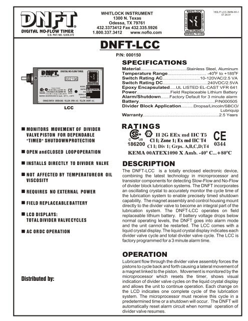
<strong>DNFT</strong>-<strong>LCC</strong><br />
P/N: 000150<br />
SPECIFICATIONS<br />
Material.....................................Stainless Steel, Aluminum<br />
0 0<br />
Temperature Range............................... -40 F to +185 F<br />
Switch Rating AC..............................10-120VAC/2.5 VA<br />
Switch Rating DC....................................240VDC/2.5VA<br />
Epoxy Encapsulated.....UL LISTED EL-CAST VFR 641<br />
Power...........................Field Replaceable Lithium Battery<br />
Alarm/Shutdown.......Factory Default for 3 minute alarm<br />
Battery.............................................................P/N000505<br />
Divider Block Application..........Dropsa/Lincoln/SBCO/<br />
Lubriquip<br />
Warranty.............................................................2.5 Years<br />
RATINGS<br />
WHITLOCK<br />
150LIT <strong>LCC</strong>-3MIN-WI-1<br />
07.26.01<br />
R II 2G EEx md IIC T5<br />
C US<br />
186200<br />
Cl I; Zone 1; Ex md IIC T4<br />
Cl I; Div 1; Grps. A,B,C,D;T4<br />
0344<br />
KEMA 00ATEX1090 X Amb. -40° C...+80°C<br />
DESCRIPTION<br />
The <strong>DNFT</strong>-<strong>LCC</strong> is a totally enclosed electronic device,<br />
combining the latest technology in microprocessor and<br />
transistor components for detecting Slow-Flow and No-Flow<br />
of divider block lubrication systems. The <strong>DNFT</strong> incorporates<br />
an oscillating crystal to accurately monitor the cycle time of<br />
the lubrication system to enable precisely timed shutdown<br />
capability. The magnet assembly and control housing mount<br />
directly to the divider valve to become an integral part of the<br />
lubrication system. The <strong>DNFT</strong>-<strong>LCC</strong> operates on field<br />
replaceable lithium battery. If battery voltage drops below<br />
normal operating levels, the <strong>DNFT</strong> goes into alarm mode<br />
and the unit cannot be restarted. The <strong>LCC</strong> comes with a<br />
liquid crystal display. The liquid crystal display indicates each<br />
divider valve cycle and total divider valve cycle. The <strong>LCC</strong> is<br />
factory programmed for a 3 minute alarm time.<br />
OPERATION<br />
Lubricant flow through the divider valve assembly forces the<br />
pistons to cycle back and forth causing a lateral movement of<br />
a magnet linked to the piston. Movement is monitored by the<br />
microprocessor which resets the timer, shows visual<br />
indication of divider valve cycles on the liquid crystal display<br />
and allows the unit to continue operation. Each change on<br />
the LCD indicates one complete cycle of the lubrication<br />
system. The microprocessor must receive this cycle in a<br />
predetermined time or a shutdown will occur. The <strong>DNFT</strong> will<br />
automatically reset alarm circuit when normal operation of<br />
divider valve resumes.<br />
1-800-337-3412<br />
www.noflo.com<br />
CE
<strong>DNFT</strong> <strong>DNFT</strong>R<br />
DIGITAL NO-FLOW TIMER<br />
TROUBLESHOOTING <strong>DNFT</strong>-<strong>LCC</strong><br />
NOTICE: WHEN MORE THAN ONE <strong>DNFT</strong> IS INSTALLED ON THE COMPRESSOR OR ENGINE, EACH <strong>DNFT</strong> MUST BE WIRED TO A SEPARATE ALARM<br />
CIRCUIT ON THE CONTROL PANEL, ANNUNCIATOR OR PLC TO SIMPLIFY TROUBLESHOOTING THE LUBRICATION SYSTEM AND <strong>DNFT</strong>.<br />
1. LCD DOES Not<br />
CHANGE, Control<br />
A. Improperly Adjusted<br />
Panel Indicates<br />
Lube No-Flow<br />
(See also, 3.Erratic shutdown)<br />
2. No Display on LCD<br />
3. After installation of<br />
<strong>DNFT</strong>, Rupture Disc is<br />
Blown and Divider Valve is<br />
Locked up.<br />
U.S. PAT. NO. 5,835,372<br />
INTERNAL VIEW OF<br />
DIVIDER VALVE<br />
B. Spring or Magnet is<br />
Broken in Magnet<br />
Assembly<br />
A. Low Battery voltage<br />
B. Defective LCD<br />
A. Wrong Magnet Housing<br />
Installed on Divider Valve<br />
(See magnet assy. Below)<br />
C. Faulty Lube Pump<br />
TYPICAL <strong>DNFT</strong> INSTALLATION<br />
O-RING<br />
OR<br />
METAL GASKET<br />
24S<br />
B. Air or Debris in<br />
Divider Valve<br />
System.<br />
ALLEN HEAD<br />
SET SCREWS (2)<br />
<strong>DNFT</strong><br />
1/8" RECESSED OPENING<br />
24S FOR RESET MAGNET<br />
PISTON ENCLOSURE<br />
PLUG<br />
DIVIDER VALVE<br />
SERVICE PROCEDURE AND / OR CORRECTION<br />
#22 AWG 18" LEADS<br />
(5) STANDARD<br />
RESET MAGNET<br />
DO NOT INSERT IN RECESSED OPENING<br />
WHILE COMPRESSOR IS RUNNING<br />
CAUTION: DISCONNECT ALL WIRING PRIOR TO WELDING ON COMPRESSOR OR SKID.<br />
Loosen set screws, slide <strong>DNFT</strong> all the way onto hex of magnet housing and<br />
torque to 25 inch pounds max.(Do not over tighten) Cycle divider valve by<br />
pumping clean oil through system with lubrication system purge gun or running<br />
compressor. If necessary, adjust <strong>DNFT</strong> 1/16“ back until LCD<br />
changes with each cycle of divider valve<br />
Loosen set screws, remove <strong>DNFT</strong> from magnet housing. Remove magnet<br />
assembly from divider valve. Remove magnet, spacer and spring. Check<br />
components for damage. Replace damaged spring or magnet and install on<br />
divider valve. If necessary, adjust <strong>DNFT</strong>, number change on LCD. Purge air from<br />
system with lubrication system purge gun.<br />
STRAIGHT OK !<br />
Loosen set screws, remove <strong>DNFT</strong> from magnet housing. Check for damaged or bent<br />
magnet housing. Remove magnet assembly from divider valve. Replace magnet<br />
C. Bent Magnet Housing housing, magnet, spring and spacer. Re-install <strong>DNFT</strong> on magnet housing. If necessary,<br />
BENT REPLACE !<br />
adjust <strong>DNFT</strong>, check for number change on LCD. Purge air from system with lubrication<br />
system purge gun.<br />
Electrical Testing of <strong>LCC</strong><br />
U.S. PAT. NO. 5,835,372 R<br />
DIGITAL NO-FLOW TIMER<br />
002196<br />
INSTRUMENT<br />
ODESSA, TX USA<br />
MODEL <strong>LCC</strong><br />
Factory Sealed<br />
RATED 10-120VAC/2.5VA<br />
R II 2G EEx md IIC T5<br />
P/N 000150<br />
C US Cl I; Zone 1; Ex md IIC T4 CE SERIAL #<br />
186200<br />
Cl I; Div 1; Grps. A,B,C,D;T4<br />
0344<br />
ALARM 3MIN<br />
KEMA 00ATEX1090 X Amb. -40° C...+80°C<br />
ORANGE-SWITCH GREEN-GND. YELLOW - OPEN - N.O. YELLOW - SHORT - N.C.<br />
1-800-337-3412<br />
1-800-337-3412<br />
WHITLOCK INSTRUMENT<br />
1300 N. Texas<br />
Odessa, TX 79761<br />
432.3373412 Fax 432.335.5926<br />
1.800.337.3412 www.noflo.com<br />
WHITLOCK<br />
INSTRUMENT<br />
ODESSA, TX USA<br />
150LIT <strong>LCC</strong>-3MIN-WI-2<br />
07.26.01<br />
Remove the battery from the <strong>DNFT</strong> per the attached instructions. Replace the<br />
battery if the voltage is below 2.5 volts using a factory recommended replacement<br />
battery.<br />
Loosen set screws, remove <strong>DNFT</strong> from magnet housing. Check for correct magnet<br />
housing for divider valve manufacturer. Remove and replace with correct magnet<br />
housing. If necessary, adjust <strong>DNFT</strong>, check for number change on LCD. Purge air from<br />
system with lubrication system purge gun.<br />
Check system pressure to insure oil is flowing to divider valves. If necessary install<br />
pressure gauge to monitor operation of lubrication system.<br />
1. Loosen outlet plugs in front of valve blocks. Fast purge the system with lubrication<br />
system purge gun until clean, clear, air free oil appears from plugs.<br />
2. Loosen each piston enclosure plug individually to purge air from behind piston Do not<br />
remove piston enclosure plugs. Tighten all divider valve plugs. Adjust <strong>DNFT</strong>. To insure<br />
proper operation of the divider block lubrication system, it is absolutely necessary<br />
that all tubing and components be filled with oil and free of air before start-up.<br />
1. NORMALLY OPEN - Attach ohmmeter to orange wires. Yellow wires should be<br />
insulated from each other. Ohmmeter should read 10 ohms or less in alarm state<br />
2. NORMALLY CLOSED - Attach ohmmeter to read red wires. Yellow wires should be<br />
shorted together. Ohmmeter should read infinity in alarm mode<br />
Check system pressure to insure oil is flowing to divider valve. If necessary, install<br />
pressure gauge to monitor operation of lubrication system. Check gauge<br />
to insure pump will build sufficient pressure to inject oil into cylinder. You cannot check for<br />
oil flow into cylinder by removing tubing from check valve and pumping<br />
oil to atmosphere. Replace pump.<br />
WHITLOCK<br />
www.noflo.com<br />
www.noflo.com<br />
YELLOW<br />
YELLOW<br />
ORANGE<br />
ORANGE<br />
GREEN<br />
Magnet Assemblies and Applications <strong>DNFT</strong> must be installed with correct magnet<br />
SBCO &TRABON<br />
O-Ring Seal<br />
7/16"-20<br />
assembly for each divider valve manufacturer.<br />
Magnet Assy # 000004<br />
Trabon Metal Gasket Seal<br />
1994 or Earlier<br />
7/16"-20<br />
Lincoln O-Ring Seal<br />
Extended Nose<br />
7/16"-20<br />
Dropsa No Gasket<br />
Raised Shoulder<br />
1-800-337-3412<br />
www.noflo.com<br />
Magnet Assy # 000011<br />
Magnet Assy # 000012<br />
Magnet Assy # 000013
<strong>DNFT</strong> <strong>DNFT</strong>R<br />
DIGITAL NO-FLOW TIMER<br />
U.S. PAT. NO. 5,835,372<br />
INTERNAL VIEW OF<br />
DIVIDER VALVE<br />
<strong>DNFT</strong>-<strong>LCC</strong><br />
INSTALLATION ON DROPSA/LINCOLN/SBCO/LUBRIQUIP DIVIDER BLOCKS.<br />
1. Loosen all Allen head set screws (A) on <strong>DNFT</strong>-<strong>LCC</strong> (B) and remove magnet housing (C). Do not remove magnet, spring, or<br />
spacer from magnet housing.<br />
2. Remove piston enclosure plug (D) from end of divider valve where <strong>DNFT</strong>-<strong>LCC</strong> will be installed. The <strong>DNFT</strong>-<strong>LCC</strong> does not<br />
have to be installed on the top divider valve. It may be installed on any convenient divider valve, top to bottom. (Notice:Do not<br />
install <strong>DNFT</strong>-<strong>LCC</strong> on Lincoln divider valves with cycle indicator pins or any Dropsa divider valve less than SMX 16.)<br />
3. Be sure O-ring or metal gasket (F) is in place on magnet housing (C). Screw magnet housing (C) into end of divider valve<br />
(E). Torque to 15 foot pounds max.<br />
4. Slide <strong>DNFT</strong>-<strong>LCC</strong> (B) all the way onto hex of magnet housing (C). Tighten set screws on hex of magnet housing. Torque 25<br />
inch pounds max.<br />
5. The LCD (G) on the <strong>DNFT</strong>-<strong>LCC</strong> indicates total divider valve cycles and changes with each cycle. This enables operator to<br />
adjust the lubricator pump for correct cycle time and oil consumption recommended by compressor manufacturer. If the number<br />
on the LCD (G) does not change with compressor running or by manually pumping oil into divider valve, the <strong>DNFT</strong>-<strong>LCC</strong> must<br />
be adjusted.<br />
6. Before adjusting <strong>DNFT</strong>-<strong>LCC</strong>, divider valve must be cycling. This can be achieved with the compressor running or by<br />
manually pumping oil through the divider valve assembly with a hand priming pump.<br />
7. Adjustment is made by sliding the <strong>DNFT</strong>-<strong>LCC</strong> (B) all the way on the hex of the magnet housing (C). Tighten set screws on<br />
hex of the magnet housing to 25 inch pounds max. Check for LCD (G) change to confirm correct adjustment. If LCD (G) does<br />
not change with divider valve cycling, adjust the <strong>DNFT</strong>-<strong>LCC</strong> back in 1/16" increments. Correct adjustment of the <strong>DNFT</strong>-<strong>LCC</strong> is<br />
confirmed by number change on the LCD (G).<br />
8. All conduit and connections should be appropriate for area classification. Notice: Conduit and fittings must be supported to<br />
avoid bending magnet housing.<br />
9. After installing magnet assembly and pre-compressor start-up, it is absolutely necessary to purge all air from divider<br />
block lubrication system. This can easily be accomplished with a lubrication system purge gun.<br />
10.<strong>DNFT</strong>-<strong>LCC</strong> must be installed with correct magnet assembly for each divider valve manufacturer.<br />
Lincoln-7/16"-20 extended nose with O- ring Dropsa-1/4” BSP with special metal spacer<br />
Trabon-1994 or earlier 7/16"-20 with metal crush gasket Trabon-1995 and later 7/16"-20 with O-ring<br />
O-RING OR<br />
METAL GASKET<br />
(F)<br />
24S<br />
24S<br />
<strong>DNFT</strong>-<strong>LCC</strong><br />
(B)<br />
DIGITAL NO-FLOW TIMER<br />
U.S. PAT. NO. 5,835,372 R<br />
002196<br />
INSTRUMENT<br />
ODESSA, TX USA<br />
MODEL <strong>LCC</strong><br />
Factory Sealed<br />
RATED 10-120VAC/2.5VA<br />
R II 2G EEx md IIC T5<br />
P/N 000150<br />
C US Cl I; Zone 1; Ex md IIC T4 CE<br />
186200<br />
SERIAL #<br />
Cl I; Div 1; Grps. A,B,C,D;T4<br />
0344<br />
KEMA 00ATEX1090 X Amb. -40° C...+80°C<br />
ALARM 3MIN<br />
ORANGE-SWITCH GREEN-GND. YELLOW - OPEN - N.O. YELLOW - SHORT - N.C.<br />
PISTON ENCLOSURE PLUG<br />
(D)<br />
DIVIDER VALVE<br />
(E)<br />
WHITLOCK INSTRUMENT<br />
1300 N. Texas<br />
Odessa, TX 79761<br />
432.3373412 Fax 432.335.5926<br />
1.800.337.3412 www.noflo.com<br />
1-800-337-3412<br />
WHITLOCK<br />
www.noflo.com<br />
MAGNET<br />
HOUSING<br />
(C)<br />
MAGNET<br />
(H)<br />
O-RING<br />
(F)<br />
CONTROL HOUSING<br />
ALLEN HEAD<br />
SET SCREWS(2)<br />
(A) SPACER<br />
POLARIZED CONNECTOR<br />
CAUTION: DISCONNECT ALL WIRING PRIOR TO WELDING ON COMPRESSOR OR SKID. WIRING LEGEND<br />
OPEN LOOP MODE<br />
000544<br />
<strong>DNFT</strong>-<strong>LCC</strong><br />
000150<br />
ORANGE<br />
ORANGE<br />
YELLOW<br />
SEE NOTE<br />
GREEN GROUND<br />
LIQUID CRYSTAL DISPLAY<br />
(G)<br />
CONTROL PANEL<br />
ANNUNCIATOR<br />
OR PLC<br />
YELLOW<br />
YELLOW<br />
ORANGE<br />
ORANGE<br />
GREEN<br />
NOTE: VIOLET WIRES MUST<br />
BE INSULATED FROM EACH<br />
OTHER AND FROM CONTACT<br />
WITH GROUND<br />
1-800-337-3412<br />
WHITLOCK<br />
INSTRUMENT<br />
ODESSA, TX USA<br />
SPRING<br />
FIELD REPLACEABLE<br />
BATTERY<br />
P/N 000505<br />
www.noflo.com<br />
www.noflo.com<br />
150LIT <strong>LCC</strong>-3MIN-WI-3<br />
07.26.01<br />
#22 AWG 18" LEADS (5)<br />
(I)<br />
1/2“ PIPE PLUG<br />
YELLOW: WIRES SHORTED - NORMALLY CLOSED OPERATION<br />
YELLOW: WIRES ISOLATED - NORMALLY OPEN OPERATION<br />
ORANGE: SWITCH ORANGE: SWITCH<br />
GREEN: CASE GROUND<br />
NOTICE: GROUND MUST BE CONNECTED . UNIT MUST BE SECURELY<br />
CLOSED LOOP MODE<br />
000544<br />
ORANGE<br />
ORANGE<br />
YELLOW<br />
SEE NOTE<br />
GREEN GROUND<br />
WIRING CONNECTIONS SHOWN FOR UNIT IN OPERATING MODE<br />
CONTROL PANEL<br />
ANNUNCIATOR<br />
OR PLC<br />
YELLOW<br />
YELLOW<br />
ORANGE<br />
ORANGE<br />
NOTE: VIOLET WIRES MUST<br />
BE SHORTED TOGETHER AND<br />
INSULATED FROM CONTACT<br />
WITH GROUND
<strong>DNFT</strong><br />
R<br />
DIGITAL NO-FLOW TIMER<br />
U.S. PAT. NO. 5,835,372<br />
<strong>DNFT</strong> BATTERY REPLACEMENT INSTRUCTIONS<br />
MAGNET<br />
HOUSING<br />
(C)<br />
MAGNET<br />
(H)<br />
O-RING<br />
(F)<br />
CONTROL HOUSING<br />
(B)<br />
WHITLOCK INSTRUMENT<br />
1300 N. Texas<br />
Odessa, TX 79761<br />
432.3373412 Fax 432.335.5926<br />
INSTRUMENT<br />
1.800.337.3412 www.noflo.com ODESSA, TX USA<br />
ALLEN HEAD<br />
SET SCREWS(2)<br />
(A) SPACER<br />
POLARIZED CONNECTOR<br />
SPRING<br />
FIELD REPLACEABLE<br />
BATTERY<br />
P/N: 000505<br />
WHITLOCK<br />
#22 AWG 18" LEADS (5)<br />
(I)<br />
1/2“ PIPE PLUG<br />
Directions for replacing the battery in the Digital No Flow Timer.<br />
1. Shut down the engine or set the bypass timer.<br />
2. Use a 3/8" ratchet to remove the 1/2" NPT Pipe plug.<br />
3. Remove the battery from the <strong>DNFT</strong> and disconnect from the polarized connector.<br />
4. Connect the new battery to the attached polarized plug.<br />
5. Reinsert the battery and reinstall 1/2" NPT Pipe plug.<br />
1-800-337-3412<br />
www.noflo.com<br />
www.noflo.com<br />
150LIT <strong>LCC</strong>-3MIN-WI-4<br />
07.26.01<br />
6. Verify the <strong>DNFT</strong> is working by pre-lubing the system and check for LCD number change.<br />
ITEMS REQUIRED FOR REPLACING THE <strong>DNFT</strong> BATTERY:<br />
(1) P/N: 000505 BATTERY or RADIO SHACK P/N: 960-0418 (alternate replacement)<br />
(1) 3/8“ RATCHET WRENCH (for removal of battery plug)<br />
For any further information or questions, please contact:<br />
WHITLOCK INSTRUMENT<br />
1300 N. Texas<br />
Odessa, TX 79761<br />
432.3373412 Fax 432.335.5926<br />
1.800.337.3412 www.noflo.com<br />
YELLOW<br />
YELLOW<br />
GREEN<br />
ORANGE<br />
ORANGE