ELECTRICAL SOLUTIONS
ELECTRICAL SOLUTIONS
ELECTRICAL SOLUTIONS

You also want an ePaper? Increase the reach of your titles
YUMPU automatically turns print PDFs into web optimized ePapers that Google loves.
A. System<br />
Overview<br />
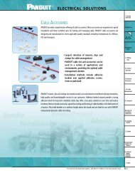
B1.Cable Ties<br />
B2. Cable<br />
Accessories<br />
B3. Stainless<br />
Steel<br />
C1. Wiring<br />
Duct<br />
C2. Surface<br />
Raceway<br />
C3. Abrasion<br />
Protection<br />
C4. Cable<br />
Management<br />
D1. Terminals<br />
D2. Power &<br />
Grounding<br />
Connectors<br />
E1. Labeling<br />
System<br />
F. Index<br />
D2.0<br />
<strong>ELECTRICAL</strong> <strong>SOLUTIONS</strong><br />
Compression Connector Reference Information<br />
B2. Cable<br />
Accessories<br />
E3. Pre-Printed<br />
& Write-On<br />
Markers<br />
E4. Lockout/<br />
Tagout<br />
& Safety<br />
Solutions<br />
F. Index<br />
CTAPs<br />
<strong>ELECTRICAL</strong> <strong>SOLUTIONS</strong><br />
Selection Guide — PAN-LUG Copper Compression Connectors<br />
for Copper Code Conductor<br />
One-Hole Lugs<br />
Two-Hole Lugs<br />
Butt Splices<br />
T Splices<br />
Parallel Splices<br />
LCAS D2.6, D2.7<br />
Short Barrel with<br />
Inspection Window<br />
LCAS-H 45° bent D2.8, D2.9<br />
LCAS-F 90° bent D2.10, D2.11<br />
LCA D2.12, D2.13<br />
LCA-H 45° bent D2.14, D2.15<br />
Standard Barrel with<br />
Inspection Window<br />
LCA-F 90° bent D2.16, D2.17<br />
LCAN narrow tongue D2.18, D2.19<br />
LCA-00 blank tongue D2.20<br />
LCB D2.21, D2.22<br />
Long Barrel no LCB-H 45° bent D2.23, D2.24<br />
Inspection Window LCB-F 90° bent D2.25, D2.26<br />
LCBH with corona relief taper D2.29<br />
LCB-W D2.27<br />
Long Barrel with<br />
LCB-WH 45° bent D2.28<br />
Inspection Window<br />
LCB-WF 90° bent D2.28<br />
Standard Barrel with<br />
Inspection Window<br />
Short Barrel<br />
LCD D2.30, D2.31<br />
LCD-H 45° bent D2.32, D2.33<br />
LCD-F 90° bent D2.34, D2.35<br />
LCDN narrow tongue D2.36<br />
LCDN-H 45° bent narrow tongue D2.37<br />
LCDN-F 90° bent narrow tongue D2.38<br />
LCD-00 blank tongue D2.39<br />
LCC D2.40, D2.41<br />
LCC-H 45° bent D2.42, D2.43<br />
Long Barrel no<br />
LCC-F 90° bent D2.44, D2.45<br />
Inspection Window<br />
LCCH with corona relief taper D2.55<br />
LCC-00 blank tongue D2.56<br />
LCC-W D2.46, D2.47, D2.48<br />
LCC-WH 45° bent D2.49, D2.50, D2.51<br />
Long Barrel with<br />
LCC-WF 90° bent D2.52, D2.53, D2.54<br />
Inspection Window<br />
LCCN-W narrow tongue D2.54<br />
LCC-00W blank tongue D2.57<br />
Standard Barrel<br />
Long Barrel<br />
Code<br />
Connector Barrel Style Type Page Number<br />
SCSS Pg. D2.58<br />
SCS D2.59<br />
SCL D2.60<br />
SCH with corona relief chamfer D2.61<br />
SCT D2.62<br />
PS D2.63<br />
CTAPF stamped and formed D2.106<br />
CTAP heavy duty extrusion D2.107<br />
TAPC black covers for CTAP Taps D2.108<br />
A. System<br />
Overview<br />
B1.Cable Ties<br />
B2. Cable<br />
Accessories<br />
B3. Stainless<br />
Steel<br />
C1. Wiring<br />
Duct<br />
C2. Surface<br />
Raceway<br />
C3. Abrasion<br />
Protection<br />
C4. Cable<br />
Management<br />
D1. Terminals<br />
D2. Power &<br />
Grounding<br />
Connectors<br />
E1. Labeling<br />
System<br />
E2. Labels<br />
E3. Pre-Printed<br />
& Write-On<br />
Markers<br />
E4. Lockout/<br />
Tagout<br />
& Safety<br />
Solutions<br />
F. Index<br />
For service and technical support, call 800-777-3300 or visit access www.panduit.com. D2.3<br />
<strong>ELECTRICAL</strong> <strong>SOLUTIONS</strong><br />
A. System<br />
Overview<br />
Code Conductor, Blank Tongue, Long Barrel Lug<br />
For Use with Stranded Copper Conductors<br />
B1.Cable Ties<br />
Type LCC-00<br />
Long barrel maximizes number of crimps and provides premium<br />
wire pull-out strength and electrical performance<br />
Color coded barrels marked with PANDUIT and specified<br />
competitor die index numbers for proper crimp die selection<br />
Enclosed barrel prevents corrosive material from entering barrel<br />
when used in harsh environments<br />
Tin plated to inhibit corrosion<br />
UL Recognized and CSA Certified to 35KV** and temperature<br />
rated to 90°C when crimped with PANDUIT and specified<br />
competitor crimping tools and dies<br />
B3. Stainless<br />
Steel<br />
W<br />
W<br />
C1. Wiring<br />
L<br />
Duct<br />
L<br />
B<br />
B<br />
C2. Surface<br />
T<br />
Raceway<br />
T<br />
Figure 1<br />
Figure 2: Two Piece Brazed<br />
Tongue Construction<br />
C3. Abrasion<br />
Protection<br />
Copper<br />
PANDUIT PANDUIT Burndy Die T&B Die Wire Strip Std.<br />
Figure Conductor<br />
Figure Dimensions (In.)<br />
Color Die Index Index Index Length Pkg.<br />
Part Number No. Size W B T L Code No.‡ No.‡ No.‡ (In.)<br />
LCC8-00-L 1 #8 AWG .60 .70 .05 2.75 Red P21 49 21 3/4<br />
Qty.<br />
50<br />
LCC6-00-L 2 #6 AWG .75 1.13 .16 5.00 Blue P24 7 24 1 1/8 50<br />
C4. Cable<br />
LCC4-00-L 2 #4 – #3 AWG .75 1.13 .16 5.06 Gray P29 8 29 1 1/8 50<br />
Management<br />
LCC2-00-Q 1<br />
STR,<br />
#2 AWG SOL<br />
#2 AWG .75 1.16 .08 4.51 Brown P33 10 33 1 1/4 25<br />
LCC1-00-E 1 #1 AWG .75 1.36 .09 4.74 Green P37 11 37 1 7/16 20<br />
D1. Terminals LCC1/0-00-X 1 1/0 AWG .80 1.44 .12 4.86 Pink P42 12 42 1 1/2 10<br />
LCC2/0-00-X 1 2/0 AWG .85 1.50 .13 4.98 Black P45 13 45 1 9/16 10<br />
LCC3/0-00-X 1 3/0 AWG .96 1.50 .13 5.03 Orange P50 14 50 1 9/16 10<br />
LCC4/0-00-X 1 4/0 AWG 1.06 1.56 .14 5.13 Purple P54 15 54 1 5/8 10<br />
LCC250-00-X 1 250 kcmil 1.17 1.60 .14 5.23 Yellow P62 16 62 1 11/16 10<br />
D2. Power &<br />
Grounding LCC300-00-X 1 300 kcmil 1.19 2.23 .16 5.94 White P66 17 66 2 5/16 10<br />
Connectors LCC350-00-X 1 350 kcmil 1.28 2.23 .17 5.99 Red P71 18 71 2 5/16 10<br />
LCC400-00-6 1 400 kcmil 1.39 2.29 .18 6.10 Blue P76 19 76 2 3/8 6<br />
LCC500-00-6 1 500 kcmil 1.54 2.49 .22 6.36 Brown P87 20 87 2 9/16 6<br />
E1. Labeling LCC600-00-6 1 600 kcmil 1.70 2.68 .26 6.63 Green P94 22 94 2 3/4 6<br />
System LCC750-00-6 1 750 kcmil 1.89 2.87 .26 7.04 Black P106 24 106 2 15/16 6<br />
LCC1000-00-3 1 1000 kcmil 2.17 2.99 .32 7.29 White P125 27 125 3 1/16 3<br />
‡See pages D2.154, D2.155, D2.156, D2.157 for tool and die information.<br />
**Consult cable manufacturer for voltage stress relief instructions with applications greater than 2000 volts.<br />
E2. Labels<br />
D2.56 Order number of pieces required, in multiples of Standard Package Quantity. Prime items appear in BOLD.<br />
A. System<br />
Overview<br />
D2.154<br />
<strong>ELECTRICAL</strong> <strong>SOLUTIONS</strong><br />
PANDUIT (See Compression Connector Tools Selection Guide,<br />
Pages D2.126–D2.128) Thomas & Betts<br />
CT-920, CT-920CH,<br />
CT-930, CT-930CH,<br />
CT-2920,<br />
CT-2930, CT-2931,<br />
CT-930LPCH➅,<br />
CT-940CH E2. Labels<br />
CT-1570 CT-1701➀ CT-1700➀ CT-720<br />
E3. Pre-Printed<br />
& Write-On<br />
Markers<br />
E4. Lockout/<br />
Tagout<br />
& Safety<br />
Solutions<br />
➂ ,<br />
CT-2940➂ UNI-DIE <br />
CT-980,<br />
CT-980CH,<br />
CT-2950➄, CT-2980,<br />
CT-2981,<br />
CT-980LPCH➅ Extended<br />
Wire Range➈ PANDUIT<br />
Part<br />
Number<br />
Wire<br />
CT-2001, TBM20S,<br />
TBM12,<br />
Std. Strip<br />
L=Lug<br />
CT-2002 TBM25S TBM5 TBM8 13642M<br />
Wire Length<br />
S=Splice Size (In.)<br />
Die Part Number / Color Code & Die Index Number / (Number Of Crimps)<br />
#14 – #10<br />
AWG<br />
LCB10 STR,<br />
12-10 P10<br />
9/16<br />
— — — — — — — — —<br />
LCC10 #12 – #10<br />
(2) (2)<br />
AWG<br />
SOL<br />
LCB8<br />
LCBN8<br />
3/4<br />
CD-720-1 CD-920-8<br />
CD-2001-8<br />
LCC8<br />
Red P21<br />
Red 21 Red 21 Red 21 Red 21<br />
#8 AWG<br />
— —<br />
Red P21 Red P21<br />
— Red P21<br />
LCCN8<br />
(3)<br />
(3) (1) (1) (1)<br />
(2)<br />
(1)<br />
(2)<br />
SCL8 1-1/16<br />
LCB6<br />
LCBN6<br />
CD-720-1 CD-920-6<br />
CD-2001-6<br />
Blue Blue<br />
LCC6<br />
Blue P24<br />
Blue 24<br />
Blue 24<br />
#6 AWG 1-1/8 — —<br />
Blue P24 Blue P24<br />
— Blue P24<br />
24 24<br />
LCCN6<br />
(3)<br />
(3)<br />
(1)<br />
(2)<br />
(1)<br />
(2)<br />
(1) (1)<br />
SCL6<br />
LCB4 #4 – #3<br />
LCBN4<br />
#4 – #2 AWG<br />
AWG<br />
1-1/16<br />
Gray CD-720-1 CD-920-4<br />
CD-2001-4<br />
Gray Gray Gray<br />
LCC4<br />
#2 AWG<br />
Gray 29<br />
STR,<br />
— — P29 Gray P29 Gray P29<br />
Gray P29<br />
29 29 29<br />
LCCN4<br />
SOL Only<br />
(3)<br />
#2 AWG<br />
(3) (2)<br />
(1)<br />
(2)<br />
(1) (1) (1)<br />
(1)<br />
SCL4 SOL 1-1/8<br />
LCB2<br />
LCBN2<br />
CD-720-1<br />
Brown<br />
CD-920-2<br />
CD-2001-2 Brown Brown Brown Brown<br />
LCC2<br />
Brown<br />
#6 – #2 AWG<br />
#2 AWG 1-1/4 — — P33<br />
Brown P33<br />
Brown P33 33 33 33 33<br />
LCCN2<br />
P33<br />
(1)<br />
(3)<br />
(1)<br />
(2) (3) (1) (1) (1)<br />
(2)<br />
SCL2<br />
LCB1<br />
LCBN1<br />
LCC1 #1 AWG<br />
LCCN1<br />
1-7/16<br />
B1.Cable Ties<br />
B2. Cable<br />
Accessories<br />
B3. Stainless<br />
Steel<br />
C1. Wiring<br />
Duct<br />
C2. Surface<br />
Raceway<br />
C3. Abrasion<br />
Protection<br />
C4. Cable<br />
Management<br />
CD-720-2<br />
D1. Terminals<br />
Green<br />
CD-920-1<br />
CD-2001-1<br />
Green Green Green<br />
Green<br />
#6 – #1 AWG<br />
— — P37<br />
Green P37<br />
Green P37 — 37 37 37<br />
P37<br />
(1)<br />
(4)<br />
(1)<br />
(2)<br />
(1) (1) (1)<br />
(2)<br />
SCL1 1-3/8<br />
LCB1/0<br />
LCBN1/0<br />
LCC1/0 1/0 1-1/2<br />
CD-720-2 CD-920-1/0<br />
CD-2001-1/0<br />
Pink Pink<br />
#6 – 1/0 AWG<br />
Pink 42<br />
D2. Power &<br />
— — — Pink P42 Pink P42<br />
Pink P42 — 42 42<br />
Grounding LCCN1/0 AWG<br />
(2)<br />
(2)<br />
(2)<br />
(2)<br />
(2)<br />
(2) (2)<br />
Connectors SCL1/0 1-3/8<br />
LCB2/0<br />
LCBN2/0<br />
CD-720-2<br />
LCC2/0 2/0 1-9/16<br />
CD-920-2/0<br />
CD-2001-2/0<br />
Black Black Black<br />
Black<br />
#4 – 2/0 AWG<br />
—<br />
E1. Labeling<br />
— — —<br />
Black P45<br />
Black P45<br />
45 45 45<br />
LCCN2/0 AWG<br />
P45<br />
(2)<br />
System<br />
(3)<br />
(3)<br />
(3) (3) (2)<br />
(3)<br />
SCL2/0 1-1/2<br />
LCB3/0<br />
LCBN3/0<br />
CD-720-2<br />
LCC3/0 3/0 1-9/16<br />
CD-920-3/0<br />
CD-2001-3/0<br />
Orange Orange Orange<br />
Orange<br />
#2 – 3/0 AWG<br />
—<br />
— — —<br />
Orange P50<br />
Orange P50<br />
50 50 50<br />
LCCN3/0 AWG<br />
P50<br />
(2)<br />
E2. Labels<br />
(3)<br />
(3)<br />
(3) (3) (2)<br />
(3)<br />
SCL3/0 1-1/2<br />
LCB4/0<br />
LCBN4/0<br />
CD-720-3<br />
CD-920-4/0<br />
CD-2001-4/0<br />
Purple Purple Purple<br />
LCC4/0 4/0<br />
Purple<br />
#1 – 4/0 AWG<br />
—<br />
1-5/8 — — —<br />
Purple P54<br />
Purple P54<br />
54 54 54<br />
LCCN4/0 AWG<br />
P54<br />
(2)<br />
E3. Pre-Printed<br />
(3)<br />
(3)<br />
(3) (3) (2)<br />
(3)<br />
& Write-On SCL4/0<br />
Markers LCB250<br />
LCBN250<br />
CD-720-3<br />
LCC250 250 1-11/16<br />
CD-920-250 1/0 AWG – CD-2001-250<br />
Yellow Yellow Yellow<br />
Yellow<br />
—<br />
— — —<br />
Yellow P62 250 kcmil Yellow P62<br />
62 62 62<br />
LCCN250 kcmil<br />
P62<br />
E4. Lockout/<br />
(3)<br />
(3)<br />
(3)<br />
(4) (4) (2)<br />
(4)<br />
Tagout SCL250 1-5/8<br />
& Safety ➀The CT-1700 and CT-1701 crimp die pockets are integrated into the tool frame. ➅Maximum size: 250 kcmil lugs and splices.<br />
Solutions<br />
➁Half width dies.<br />
➆Requires U die adapter.<br />
➂CD-920 dies can be used with CT-940CH and CT-2940 tools with<br />
➇Minimum size: #4 AWG lugs and splices.<br />
CD-940-DA adapter.<br />
➈Extended wire range when crimped with these PANDUIT<br />
➃CD-940 dies to be used exclusively with CT-940CH and CT-2940 tools.<br />
F. Index ➄Maximum size: 500 kcmil lugs and 250 kcmil splices.<br />
® UNI-DIE <br />
For use with Installation Tooling and Die Selections for:<br />
Copper Types LCB, LCBN, LCC, LCCN and SCL<br />
Conductors<br />
Dieless Crimping Tools.<br />
Selection Guide<br />
Provides a quick and easy method to select the proper connector to meet the<br />
specific application requirements<br />
Conductor Type<br />
Stud Hole Configuration<br />
Barrel Style<br />
Product Type and Page Number<br />
Product Page<br />
Includes all necessary information for part identification and selection<br />
Agency Listings<br />
Features and Benefits<br />
Full Color Photo and Two-View Drawing<br />
PANDUIT and Competitor Die Information<br />
Page Reference for PANDUIT and Competitor Installation<br />
Tooling and Die Selection Charts<br />
Installation Tooling and Die Selection Chart<br />
Contains comprehensive tool and die installation information for PANDUIT compression<br />
connectors with both PANDUIT and competitor tools<br />
Page Reference to Compression Connector Tools Selection Guide for<br />
Detailed Information on PANDUIT Tools<br />
PANDUIT and Competitor Tools<br />
Product Type Listed by Conductor Size<br />
Die Part Number, Color Code, Die Index Number and Number of Crimps for<br />
Each Product Type and Tool Combination
<strong>ELECTRICAL</strong> <strong>SOLUTIONS</strong><br />
PAN-LUG COMPRESSION CONNECTORS<br />
PANDUIT ® PAN-LUG Compression Connectors provide permanent terminations for a variety of<br />
power and grounding applications, with innovation, highest reliability and lowest installed cost.<br />
PANDUIT offers the first and only copper compression lugs and splices that meet Network<br />
Equipment-Building Systems (NEBS) Level 3 requirements as tested by Telcordia Technologies.<br />
NEBS Level 3 assures that product performance is suitable for equipment applications that<br />
demand minimal service interruptions over the life span of the equipment.<br />
Functional product information is marked directly on<br />
the connector, facilitating the identification, ordering<br />
and usage of the compression connector<br />
Color coded to facilitate quick identification of the<br />
proper crimping die<br />
Made from high strength, high conductivity<br />
electrolytic copper and aluminum alloy materials to<br />
provide optimum connectivity for power and<br />
grounding applications<br />
UL Listed or Recognized, CSA Certified, ABS Type<br />
Approved and tested by Telcordia – meets NEBS Level<br />
3, as noted<br />
Terminations using PANDUIT ® PAN-LUG Compression<br />
Connectors are also UL Listed and CSA Certified with<br />
specified competitor tools<br />
Wide assortment of manual, controlled cycle, battery<br />
operated hydraulic and pneumatic crimping tools for<br />
reliable connections at the lowest installed cost<br />
PANDUIT ® PAN-LUG Compression Connectors are designed for use with many different code and<br />
flex conductor types and are available in a broad range of styles and sizes including copper<br />
one-hole,two-hole and blank tongue lugs and splices; aluminum one-hole and two-hole lugs and<br />
splices; copper CTAP style taps; copper in-line reducing splices; and innovative copper HTAPs with<br />
snap-on clear covers. PANDUIT offers a wide assortment of PAN-LUG Power and Grounding<br />
Connectors to meet customer needs and today’s application requirements.<br />
For service and technical support, call 800-777-3300 or visit www.panduit.com.<br />
A. System<br />
Overview<br />
B1.Cable Ties<br />
B2. Cable<br />
Accessories<br />
B3. Stainless<br />
Steel<br />
C1. Wiring<br />
Duct<br />
C2. Surface<br />
Raceway<br />
C3. Abrasion<br />
Protection<br />
C4. Cable<br />
Management<br />
D1. Terminals<br />
D2. Power &<br />
Grounding<br />
Connectors<br />
E1. Labeling<br />
System<br />
E2. Labels<br />
E3. Pre-Printed<br />
& Write-On<br />
Markers<br />
E4. Lockout/<br />
Tagout<br />
& Safety<br />
Solutions<br />
F. Index<br />
D2.1
A. System<br />
Overview<br />
B1.Cable Ties<br />
B2. Cable<br />
Accessories<br />
B3. Stainless<br />
Steel<br />
C1. Wiring<br />
Duct<br />
C2. Surface<br />
Raceway<br />
C3. Abrasion<br />
Protection<br />
C4. Cable<br />
Management<br />
D1. Terminals<br />
D2. Power &<br />
Grounding<br />
Connectors<br />
E1. Labeling<br />
System<br />
E2. Labels<br />
E3. Pre-Printed<br />
& Write-On<br />
Markers<br />
E4. Lockout/<br />
Tagout<br />
& Safety<br />
Solutions<br />
F. Index<br />
D2.2<br />
<strong>ELECTRICAL</strong> <strong>SOLUTIONS</strong><br />
Features and Benefits – PAN-LUG Compression Connectors<br />
Bolded features are unique to PANDUIT<br />
Color coded bands for<br />
proper die selection<br />
and crimp placement<br />
Easy-to-read, color<br />
coded die index numbers<br />
for PANDUIT and<br />
specified competitor<br />
crimping dies for<br />
selection<br />
Made from seamless,<br />
high conductivity copper<br />
tubing and electro tin<br />
plated and burnished to<br />
inhibit corrosion<br />
Easy-to-read,<br />
color coded<br />
die index<br />
number for<br />
PANDUIT<br />
crimping dies,<br />
legible after<br />
crimping, for<br />
selection<br />
Conductor sizes for<br />
each tap pocket<br />
marked on part<br />
Copper Lugs<br />
Copper HTAPs<br />
Internally beveled barrel end<br />
for easy conductor insertion<br />
Easy-to-read, color coded<br />
die index numbers for<br />
PANDUIT and specified<br />
competitor crimping dies<br />
for selection<br />
Internally beveled barrel<br />
end for easy conductor<br />
insertion (types LCCF and<br />
LCAF available with flared<br />
entry for flex conductor)<br />
Inspection windows<br />
available to<br />
assure complete<br />
conductor insertion<br />
Part number, stud<br />
size and conductor<br />
size marked on part<br />
for easy identification<br />
Part number and agency<br />
listings marked on part<br />
for easy identification<br />
Made from high<br />
conductivity copper<br />
and electro tin plated<br />
to inhibit corrosion<br />
Made from seamless, high<br />
conductivity copper tubing<br />
and electro tin plated and<br />
burnished to inhibit corrosion<br />
Compression connector<br />
crimping tools speed<br />
installation and reduce<br />
total installed cost. See<br />
pages D2.123 – D2.186.<br />
Slotted design to<br />
reduce installation<br />
time when used<br />
with PANDUIT cable<br />
ties (included)<br />
Easy-to-read die index<br />
numbers for PANDUIT<br />
and specified<br />
competitor crimping<br />
dies for selection<br />
Part number and<br />
conductor size marked on<br />
part for easy identification<br />
Made from seamless<br />
wrought aluminum and<br />
electro tin plated to<br />
inhibit corrosion<br />
Optically clear to allow<br />
360° inspections<br />
Made from high<br />
impact strength<br />
self-extinguishing<br />
plastic with UL94V-0<br />
flammability rating<br />
and minimum<br />
oxygen index of 28<br />
Built-in flanges<br />
retain HTAP in cover<br />
Easy to assemble<br />
snap-on design<br />
Molded in flash<br />
barriers protect against<br />
electrical flash over<br />
Copper In-Line Reducing Splices<br />
PANDUIT designs and<br />
manufactures a full line of<br />
labeling products, software<br />
and printers to assist you with<br />
your labeling requirements.<br />
See pages E1.1 – E2.30.<br />
Aluminum Lugs<br />
Color coded end plugs<br />
for proper die selection<br />
Clear Covers for Copper HTAPs<br />
Compact size provides low<br />
profile installation<br />
Color coded for proper<br />
die selection<br />
Inspection windows to assure<br />
complete conductor insertion<br />
Crimping areas marked on each<br />
barrel for proper crimp placement<br />
Crimping areas<br />
marked on part for<br />
proper crimp placement<br />
Factory pre-filled<br />
with oxide inhibitor<br />
to prevent oxidation<br />
Retainer clips to hold labels inside<br />
cover*. Retainer clips have a writeon<br />
surface for manual marking<br />
Corresponding<br />
PANDUIT HTAP part<br />
number, voltage<br />
rating and<br />
temperature rating<br />
molded into cover<br />
half for easy<br />
identification<br />
Low profile design<br />
minimizes space<br />
requirements<br />
Flexible fingers closely conform to<br />
conductor preventing foreign objects<br />
from entering cover<br />
*Labels shown printed with PANDUIT LS7 Printer.<br />
See page E1.8<br />
Part number and conductor<br />
size and type marked on<br />
part for easy identification<br />
Heat shrink tubing provides<br />
an economical and easy way<br />
to insulate, protect, harness<br />
and color code electrical and<br />
electronic components.<br />
See pages C3.10 – C3.29.
<strong>ELECTRICAL</strong> <strong>SOLUTIONS</strong><br />
Selection Guide – PAN-LUG Copper Compression Connectors<br />
for Copper Code Conductor<br />
One-Hole Lugs<br />
Two-Hole Lugs<br />
Butt Splices<br />
T Splices<br />
Parallel Splices<br />
CTAPs<br />
Short Barrel with<br />
Inspection Window<br />
Standard Barrel with<br />
Inspection Window<br />
Long Barrel no<br />
Inspection Window<br />
Long Barrel with<br />
Inspection Window<br />
Standard Barrel with<br />
Inspection Window<br />
Long Barrel no<br />
Inspection Window<br />
Long Barrel with<br />
Inspection Window<br />
Short Barrel<br />
Standard Barrel<br />
Long Barrel<br />
Code<br />
Connector Barrel Style Type Page Number<br />
LCAS D2.6, D2.7<br />
LCAS-H 45° bent D2.8, D2.9<br />
LCAS-F 90° bent D2.10, D2.11<br />
LCA D2.12, D2.13<br />
LCA-H 45° bent D2.14, D2.15<br />
LCA-F 90° bent D2.16, D2.17<br />
LCAN narrow tongue D2.18, D2.19<br />
LCA-00 blank tongue D2.20<br />
LCB D2.21, D2.22<br />
LCB-H 45° bent D2.23, D2.24<br />
LCB-F 90° bent D2.25, D2.26<br />
LCBH with corona relief taper D2.29<br />
LCB-W D2.27<br />
LCB-WH 45° bent D2.28<br />
LCB-WF 90° bent D2.28<br />
LCD D2.30, D2.31<br />
LCD-H 45° bent D2.32, D2.33<br />
LCD-F 90° bent D2.34, D2.35<br />
LCDN narrow tongue D2.36<br />
LCDN-H 45° bent narrow tongue D2.37<br />
LCDN-F 90° bent narrow tongue D2.38<br />
LCD-00 blank tongue D2.39<br />
LCC D2.40, D2.41<br />
LCC-H 45° bent D2.42, D2.43<br />
LCC-F 90° bent D2.44, D2.45<br />
LCCH with corona relief taper D2.55<br />
LCC-00 blank tongue D2.56<br />
LCC-W D2.46, D2.47, D2.48<br />
LCC-WH 45° bent D2.49, D2.50, D2.51<br />
LCC-WF 90° bent D2.52, D2.53, D2.54<br />
LCCN-W narrow tongue D2.54<br />
LCC-00W blank tongue D2.57<br />
SCSS SCSS Pg. D2.58<br />
SCS D2.59<br />
SCL D2.60<br />
SCH with corona relief chamfer D2.61<br />
SCT D2.62<br />
PS D2.63<br />
CTAPF stamped and formed D2.106<br />
CTAP heavy duty extrusion D2.107<br />
TAPC black covers for CTAP Taps D2.108<br />
For service and technical support, call 800-777-3300 or visit www.panduit.com.<br />
A. System<br />
Overview<br />
B1.Cable Ties<br />
B2. Cable<br />
Accessories<br />
B3. Stainless<br />
Steel<br />
C1. Wiring<br />
Duct<br />
C2. Surface<br />
Raceway<br />
C3. Abrasion<br />
Protection<br />
C4. Cable<br />
Management<br />
D1. Terminals<br />
D2. Power &<br />
Grounding<br />
Connectors<br />
E1. Labeling<br />
System<br />
E2. Labels<br />
E3. Pre-Printed<br />
& Write-On<br />
Markers<br />
E4. Lockout/<br />
Tagout<br />
& Safety<br />
Solutions<br />
F. Index<br />
D2.3
A. System<br />
Overview<br />
B1.Cable Ties<br />
B2. Cable<br />
Accessories<br />
B3. Stainless<br />
Steel<br />
C1. Wiring<br />
Duct<br />
C2. Surface<br />
Raceway<br />
C3. Abrasion<br />
Protection<br />
C4. Cable<br />
Management<br />
D1. Terminals<br />
D2. Power &<br />
Grounding<br />
Connectors<br />
E1. Labeling<br />
System<br />
E2. Labels<br />
E3. Pre-Printed<br />
& Write-On<br />
Markers<br />
E4. Lockout/<br />
Tagout<br />
& Safety<br />
Solutions<br />
F. Index<br />
D2.4<br />
<strong>ELECTRICAL</strong> <strong>SOLUTIONS</strong><br />
Selection Guide – PAN-LUG Copper Compression<br />
Connectors for Copper Code and /or Flex Conductor<br />
One-Hole Lugs<br />
Two-Hole Lugs<br />
Butt Splices<br />
with Flared<br />
Entry Flex<br />
Reducing Splices<br />
with Inspection<br />
Window<br />
Code & Flex<br />
HTAPs<br />
Code & Flex<br />
Standard Barrel with<br />
Inspection Window<br />
Code & Flex<br />
Standard Barrel<br />
with Inspection<br />
Window and Flared<br />
Entry Flex<br />
Long Barrel with<br />
Inspection Window<br />
Code & Flex<br />
Standard Barrel with<br />
Inspection Window<br />
Code & Flex<br />
Long Barrel no<br />
Inspection Window<br />
Flared Entry Flex<br />
Long Barrel with<br />
Inspection Window<br />
Code & Flex<br />
Code Flex<br />
Connector Barrel Style Type Page Number<br />
LCAX D2.64, D2.65<br />
LCAX-H 45° bent D2.66, D2.67<br />
LCAX-F 90° bent D2.68, D2.69<br />
LCAXN narrow tongue D2.70<br />
LCAXN-H 45° bent narrow tongue D2.70<br />
LCAXN-F 90° bent narrow tongue D2.71<br />
LCAF D2.72, D2.73<br />
LCAF-H 45° bent D2.74, D2.75<br />
LCAF-F 90° bent D2.76, D2.77<br />
LCBX D2.78<br />
LCBX-H 45° bent D2.79<br />
LCBX-F 90° bent D2.80<br />
LCDX D2.81, D2.82<br />
LCDX-H 45° bent D2.83, D2.84<br />
LCDX-F 90° bent D2.85, D2.86<br />
LCDXN narrow tongue D2.87<br />
LCDXN-H 45° bent narrow tongue D2.88<br />
LCDXN-F 90° bent narrow tongue D2.88<br />
LCCF D2.95, D2.96<br />
LCCF-H 45° bent D2.97, D2.98<br />
LCCF-F 90° bent D2.99, D2.100<br />
LCCX D2.89, D2.90<br />
LCCX-H 45° bent D2.91, D2.92<br />
LCCX-F 90° bent D2.93, D2.94<br />
SCSF D2.101<br />
RSCK kits with reducing splice and<br />
clear heat shrink D2.102, D2.103<br />
RSC reducing splices D2.104, D2.105<br />
HTWC kits with HTAPs and clear covers D2.109<br />
HTCT taps D2.110, D2.111<br />
CLRCVR clear covers for HTCT taps D2.111
<strong>ELECTRICAL</strong> <strong>SOLUTIONS</strong><br />
Selection Guide – PAN-LUG Aluminum Compression Connectors<br />
for Aluminum or Copper Code Conductor<br />
One-Hole Lugs<br />
Two-Hole Lugs<br />
Butt Splices<br />
Reducing Splices<br />
Bi-Metallic Pin<br />
Connectors<br />
for Aluminum<br />
Conductors Only<br />
HTAP Taps<br />
Belleville Washers<br />
Joint<br />
Compounds<br />
Part Number System for PAN-LUG Compression Lugs<br />
LCD<br />
Type<br />
Ex: LCD Lug, Copper Two<br />
Hole Standard Barrel<br />
LAA D2.115<br />
LAB D2.116<br />
SA D2.118<br />
SAR D2.119<br />
BPC D2.120<br />
HTAP D2.121<br />
TAPC black covers for HTAP taps D2.108<br />
CW D2.117, D2.223<br />
CMP D2.122, D2.223<br />
2/0 — —<br />
38 D F X<br />
Conductor<br />
Size<br />
Connector<br />
Stud Hole<br />
Size<br />
10 = #10<br />
14 = 1/4"<br />
56 = 5/16"<br />
38 = 3/8"<br />
12 = 1/2"<br />
58 = 5/8"<br />
34 = 3/4"<br />
78 = 7/8"<br />
00 = Blank Tongue*<br />
* LCA, LCC<br />
and LCD<br />
styles only<br />
Two Stud<br />
Hole Spacing<br />
A = .625"<br />
B = .750"<br />
C = .875"<br />
D = 1.0"<br />
E = 1.25"<br />
G = 1.5"<br />
J = .5"<br />
K=2"<br />
M = 1.375"<br />
P = .688"<br />
Q = 1.125"<br />
No Letter = 1.75"<br />
Type Page Number<br />
Tongue Angle<br />
H = 45° Angle<br />
F = 90° Angle<br />
No Letter = Straight<br />
Standard Package Size<br />
1=1<br />
2=2<br />
3=3<br />
5=5<br />
6=6<br />
X=10<br />
E=20<br />
Q=25<br />
L=50<br />
For service and technical support, call 800-777-3300 or visit www.panduit.com.<br />
A. System<br />
Overview<br />
B1.Cable Ties<br />
B2. Cable<br />
Accessories<br />
B3. Stainless<br />
Steel<br />
C1. Wiring<br />
Duct<br />
C2. Surface<br />
Raceway<br />
C3. Abrasion<br />
Protection<br />
C4. Cable<br />
Management<br />
D1. Terminals<br />
D2. Power &<br />
Grounding<br />
Connectors<br />
E1. Labeling<br />
System<br />
E2. Labels<br />
E3. Pre-Printed<br />
& Write-On<br />
Markers<br />
E4. Lockout/<br />
Tagout<br />
& Safety<br />
Solutions<br />
F. Index<br />
D2.5
A. System<br />
Overview<br />
B1.Cable Ties<br />
B2. Cable<br />
Accessories<br />
B3. Stainless<br />
Steel<br />
C1. Wiring<br />
Duct<br />
C2. Surface<br />
Raceway<br />
C3. Abrasion<br />
Protection<br />
C4. Cable<br />
Management<br />
D1. Terminals<br />
D2. Power &<br />
Grounding<br />
Connectors<br />
E1. Labeling<br />
System<br />
E2. Labels<br />
E3. Pre-Printed<br />
& Write-On<br />
Markers<br />
E4. Lockout/<br />
Tagout<br />
& Safety<br />
Solutions<br />
F. Index<br />
D2.6<br />
<strong>ELECTRICAL</strong> <strong>SOLUTIONS</strong><br />
Code Conductor, One-Hole, Short Barrel with Window Lug<br />
For Use with Stranded Copper Conductors<br />
Type LCAS<br />
Short barrel for limited space applications<br />
Color coded barrels marked with PANDUIT and specified<br />
competitor die index numbers for proper crimp die selection<br />
Inspection window to visually assure full conductor insertion<br />
Tin plated to inhibit corrosion<br />
T<br />
UL Listed and CSA Certified to 35KV** and temperature rated to<br />
90°C when crimped with PANDUIT and specified competitor<br />
crimping tools and dies<br />
Tested by Telcordia – meets NEBS Level 3<br />
American Bureau of Shipping Type Approved<br />
Order number of pieces required, in multiples of Standard Package Quantity. Prime items appear in BOLD.<br />
W<br />
INSPECTION<br />
WINDOW<br />
Copper<br />
Conductor<br />
Stud Hole<br />
Size<br />
Figure Dimensions (In.)<br />
PANDUIT<br />
Color<br />
PANDUIT<br />
Die Index<br />
Burndy Die<br />
Index<br />
T&B Die<br />
Index<br />
Wire Strip<br />
Length<br />
Std.<br />
Pkg.<br />
Part Number<br />
Size (In.) W B T L Code No.‡ No.‡ No.‡ (In.) Qty.<br />
LCAS8-10-L<br />
#10 .41 .42 .08 1.11 Red P21 49 21 1/2 50<br />
LCAS8-14-L 1/4 .48 .42 .07 1.20 Red P21 49 21 1/2 50<br />
LCAS8-56-L<br />
#8 AWG<br />
5/16 .56 .42 .05 1.32 Red P21 49 21 1/2 50<br />
LCAS8-38-L 3/8 .60 .42 .05 1.42 Red P21 49 21 1/2 50<br />
LCAS6-10-L<br />
#10 .45 .48 .09 1.19 Blue P24 7 24 9/16 50<br />
LCAS6-14-L 1/4 .48 .48 .08 1.28 Blue P24 7 24 9/16 50<br />
LCAS6-56-L<br />
#6 AWG<br />
5/16 .56 .48 .07 1.40 Blue P24 7 24 9/16 50<br />
LCAS6-38-L 3/8 .62 .48 .06 1.50 Blue P24 7 24 9/16 50<br />
LCAS4-10-L<br />
#10 .55 .53 .09 1.26 Gray P29 8 29 5/8 50<br />
LCAS4-14-L 1/4 .55 .53 .09 1.35 Gray P29 8 29 5/8 50<br />
LCAS4-56-L<br />
#4 AWG<br />
5/16 .55 .53 .09 1.47 Gray P29 8 29 5/8 50<br />
LCAS4-38-L 3/8 .62 .53 .07 1.57 Gray P29 8 29 5/8 50<br />
LCAS2-14-Q<br />
1/4 .60 .57 .10 1.46 Brown P33 10 33 5/8 25<br />
LCAS2-56-Q 5/16 .66 .57 .10 1.58 Brown P33 10 33 5/8 25<br />
LCAS2-38-Q<br />
#2 AWG<br />
3/8 .66 .57 .10 1.66 Brown P33 10 33 5/8 25<br />
LCAS2-12-Q 1/2 .75 .57 .08 1.89 Brown P33 10 33 5/8 25<br />
LCAS1-14-E<br />
1/4 .70 .59 .11 1.50 Green P37 11 37 11/16 20<br />
LCAS1-56-E 5/16 .70 .59 .11 1.63 Green P37 11 37 11/16 20<br />
LCAS1-38-E<br />
#1 AWG<br />
3/8 .70 .59 .11 1.70 Green P37 11 37 11/16 20<br />
LCAS1-12-E 1/2 .75 .59 .09 1.94 Green P37 11 37 11/16 20<br />
LCAS1/0-14-X<br />
1/4 .76 .66 .12 1.67 Pink P42 12 42 3/4 10<br />
LCAS1/0-56-X 5/16 .76 .66 .12 1.72 Pink P42 12 42 3/4 10<br />
LCAS1/0-38-X<br />
1/0 AWG<br />
3/8 .76 .66 .12 1.80 Pink P42 12 42 3/4 10<br />
LCAS1/0-12-X 1/2 .80 .66 .12 2.03 Pink P42 12 42 3/4 10<br />
LCAS2/0-14-X<br />
1/4 .85 .72 .13 1.82 Black P45 13 45 3/4 10<br />
LCAS2/0-56-X 5/16 .85 .72 .13 1.82 Black P45 13 45 3/4 10<br />
LCAS2/0-38-X<br />
2/0 AWG<br />
3/8 .85 .72 .13 1.89 Black P45 13 45 3/4 10<br />
LCAS2/0-12-X 1/2 .85 .72 .13 2.14 Black P45 13 45 3/4 10<br />
‡See pages D2.148, D2.149 for tool and die information.<br />
**Consult cable manufacturer for voltage stress relief instructions with applications greater than 2000 volts.<br />
L<br />
B
<strong>ELECTRICAL</strong> <strong>SOLUTIONS</strong><br />
Code Conductor, One-Hole, Short Barrel with Window Lug (continued)<br />
Copper<br />
Conductor<br />
Stud Hole<br />
Size<br />
Figure Dimensions (In.)<br />
PANDUIT<br />
Color<br />
PANDUIT<br />
Die Index<br />
Burndy Die<br />
Index<br />
T&B Die<br />
Index<br />
Wire Strip<br />
Length<br />
Std.<br />
Pkg.<br />
Part Number<br />
Size (In.) W B T L Code No.‡ No.‡ No.‡ (In.) Qty.<br />
LCAS3/0-14-X<br />
1/4 .96 .83 .13 1.97 Orange P50 14 50 7/8 10<br />
LCAS3/0-56-X 5/16 .96 .83 .13 1.97 Orange P50 14 50 7/8 10<br />
LCAS3/0-38-X<br />
3/0 AWG<br />
3/8 .96 .83 .13 2.03 Orange P50 14 50 7/8 10<br />
LCAS3/0-12-X 1/2 .96 .83 .13 2.28 Orange P50 14 50 7/8 10<br />
LCAS4/0-14-X<br />
1/4 1.06 .91 .14 2.08 Purple P54 15 54 1 10<br />
LCAS4/0-56-X 5/16 1.06 .91 .14 2.10 Purple P54 15 54 5/16 10<br />
LCAS4/0-38-X<br />
4/0 AWG<br />
3/8 1.06 .91 .14 2.17 Purple P54 15 54 1 10<br />
LCAS4/0-12-X 1/2 1.06 .91 .14 2.40 Purple P54 15 54 1 10<br />
LCAS250-14-X<br />
1/4 1.17 1.03 .14 2.25 Yellow P62 16 62 1 1/8 10<br />
LCAS250-56-X 5/16 1.17 1.03 .14 2.25 Yellow P62 16 62 1 1/8 10<br />
LCAS250-38-X<br />
250 kcmil<br />
3/8 1.17 1.03 .14 2.32 Yellow P62 16 62 1 1/8 10<br />
LCAS250-12-X 1/2 1.17 1.03 .14 2.56 Yellow P62 16 62 1 1/8 10<br />
‡See pages D2.148, D2.149 for tool and die information.<br />
**Consult cable manufacturer for voltage stress relief instructions with applications greater than 2000 volts.<br />
For service and technical support, call 800-777-3300 or visit www.panduit.com.<br />
A. System<br />
Overview<br />
B1.Cable Ties<br />
B2. Cable<br />
Accessories<br />
B3. Stainless<br />
Steel<br />
C1. Wiring<br />
Duct<br />
C2. Surface<br />
Raceway<br />
C3. Abrasion<br />
Protection<br />
C4. Cable<br />
Management<br />
D1. Terminals<br />
D2. Power &<br />
Grounding<br />
Connectors<br />
E1. Labeling<br />
System<br />
E2. Labels<br />
E3. Pre-Printed<br />
& Write-On<br />
Markers<br />
E4. Lockout/<br />
Tagout<br />
& Safety<br />
Solutions<br />
F. Index<br />
D2.7
A. System<br />
Overview<br />
B1.Cable Ties<br />
B2. Cable<br />
Accessories<br />
B3. Stainless<br />
Steel<br />
C1. Wiring<br />
Duct<br />
C2. Surface<br />
Raceway<br />
C3. Abrasion<br />
Protection<br />
C4. Cable<br />
Management<br />
D1. Terminals<br />
D2. Power &<br />
Grounding<br />
Connectors<br />
E1. Labeling<br />
System<br />
E2. Labels<br />
E3. Pre-Printed<br />
& Write-On<br />
Markers<br />
E4. Lockout/<br />
Tagout<br />
& Safety<br />
Solutions<br />
F. Index<br />
D2.8<br />
<strong>ELECTRICAL</strong> <strong>SOLUTIONS</strong><br />
Code Conductor, One-Hole, Short Barrel with Window Lug, 45° Angle<br />
For Use with Stranded Copper Conductors<br />
Type LCAS-H<br />
Short barrel for limited space applications<br />
Color coded barrels marked with PANDUIT and specified<br />
competitor die index numbers for proper crimp die selection<br />
Inspection window to visually assure full conductor insertion<br />
Tin plated to inhibit corrosion<br />
UL Listed and CSA Certified to 35KV** and temperature rated to<br />
90°C when crimped with PANDUIT and specified competitor<br />
crimping tools and dies<br />
Tested by Telcordia – meets NEBS Level 3<br />
American Bureau of Shipping Type Approved<br />
Copper<br />
Conductor<br />
Stud Hole<br />
Size<br />
Figure Dimensions (In.)<br />
PANDUIT<br />
Color<br />
PANDUIT<br />
Die Index<br />
Burndy Die<br />
Index<br />
T&B Die<br />
Index<br />
Wire Strip<br />
Length<br />
Std.<br />
Pkg.<br />
Part Number<br />
Size (In.) W B T L Code No.‡ No.‡ No.‡ (In.) Qty.<br />
LCAS8-10H-L<br />
#10 .41 .42 .08 1.00 Red P21 49 21 1/2 50<br />
LCAS8-14H-L 1/4 .48 .42 .07 1.09 Red P21 49 21 1/2 50<br />
LCAS8-56H-L<br />
#8 AWG<br />
5/16 .56 .42 .05 1.20 Red P21 49 21 1/2 50<br />
LCAS8-38H-L 3/8 .60 .42 .05 1.30 Red P21 49 21 1/2 50<br />
LCAS6-10H-L<br />
#10 .45 .48 .09 1.06 Blue P24 7 24 9/16 50<br />
LCAS6-14H-L 1/4 .48 .48 .08 1.14 Blue P24 7 24 9/16 50<br />
LCAS6-56H-L<br />
#6 AWG<br />
5/16 .56 .48 .07 1.26 Blue P24 7 24 9/16 50<br />
LCAS6-38H-L 3/8 .62 .48 .06 1.35 Blue P24 7 24 9/16 50<br />
LCAS4-10H-L<br />
#10 .55 .53 .09 1.12 Gray P29 8 29 5/8 50<br />
LCAS4-14H-L 1/4 .55 .53 .09 1.21 Gray P29 8 29 5/8 50<br />
LCAS4-56H-L<br />
#4 AWG<br />
5/16 .55 .53 .09 1.33 Gray P29 8 29 5/8 50<br />
LCAS4-38H-L 3/8 .62 .53 .07 1.42 Gray P29 8 29 5/8 50<br />
LCAS2-14H-Q<br />
1/4 .60 .57 .10 1.27 Brown P33 10 33 5/8 25<br />
LCAS2-56H-Q 5/16 .66 .57 .10 1.39 Brown P33 10 33 5/8 25<br />
LCAS2-38H-Q<br />
#2 AWG<br />
3/8 .66 .57 .10 1.46 Brown P33 10 33 5/8 25<br />
LCAS2-12H-Q 1/2 .75 .57 .08 1.68 Brown P33 10 33 5/8 25<br />
LCAS1-14H-E<br />
1/4 .70 .59 .11 1.29 Green P37 11 37 11/16 20<br />
LCAS1-56H-E 5/16 .70 .59 .11 1.42 Green P37 11 37 11/16 20<br />
LCAS1-38H-E<br />
#1 AWG<br />
3/8 .70 .59 .11 1.49 Green P37 11 37 11/16 20<br />
LCAS1-12H-E 1/2 .75 .59 .09 1.73 Green P37 11 37 11/16 20<br />
LCAS1/0-14H-X<br />
1/4 .76 .66 .12 1.43 Pink P42 12 42 3/4 10<br />
LCAS1/0-56H-X 5/16 .76 .66 .12 1.49 Pink P42 12 42 3/4 10<br />
LCAS1/0-38H-X<br />
1/0 AWG<br />
3/8 .76 .66 .12 1.56 Pink P42 12 42 3/4 10<br />
LCAS1/0-12H-X 1/2 .80 .66 .12 1.79 Pink P42 12 42 3/4 10<br />
LCAS2/0-14H-X<br />
1/4 .85 .72 .13 1.58 Black P45 13 45 3/4 10<br />
LCAS2/0-56H-X 5/16 .85 .72 .13 1.58 Black P45 13 45 3/4 10<br />
LCAS2/0-38H-X<br />
2/0 AWG<br />
3/8 .85 .72 .13 1.64 Black P45 13 45 3/4 10<br />
LCAS2/0-12H-X 1/2 .85 .72 .13 1.89 Black P45 13 45 3/4 10<br />
Order number of pieces required, in multiples of Standard Package Quantity. Prime items appear in BOLD.<br />
T<br />
W<br />
INSPECTION<br />
WINDOW<br />
‡See pages D2.148, D2.149 for tool and die information.<br />
**Consult cable manufacturer for voltage stress relief instructions with applications greater than 2000 volts.<br />
L<br />
B<br />
45˚
<strong>ELECTRICAL</strong> <strong>SOLUTIONS</strong><br />
Code Conductor, One-Hole, Short Barrel with Window Lug, 45° Angle<br />
(continued)<br />
Copper<br />
Conductor<br />
Stud Hole<br />
Size<br />
Figure Dimensions (In.)<br />
PANDUIT<br />
Color<br />
PANDUIT<br />
Die Index<br />
Burndy Die<br />
Index<br />
T&B Die<br />
Index<br />
Wire Strip<br />
Length<br />
Std.<br />
Pkg.<br />
Part Number<br />
Size (In.) W B T L Code No.‡ No.‡ No.‡ (In.) Qty.<br />
LCAS3/0-14H-X<br />
1/4 .96 .83 .13 1.68 Orange P50 14 50 7/8 10<br />
LCAS3/0-56H-X 5/16 .96 .83 .13 1.68 Orange P50 14 50 7/8 10<br />
LCAS3/0-38H-X<br />
3/0 AWG<br />
3/8 .96 .83 .13 1.74 Orange P50 14 50 7/8 10<br />
LCAS3/0-12H-X 1/2 .96 .83 .13 1.99 Orange P50 14 50 7/8 10<br />
LCAS4/0-14H-X<br />
1/4 1.06 .91 .14 1.77 Purple P54 15 54 1 10<br />
LCAS4/0-56H-X 5/16 1.06 .91 .14 1.78 Purple P54 15 54 1 10<br />
LCAS4/0-38H-X<br />
4/0 AWG<br />
3/8 1.06 .91 .14 1.85 Purple P54 15 54 1 10<br />
LCAS4/0-12H-X 1/2 1.06 .91 .14 2.08 Purple P54 15 54 1 10<br />
LCAS250-14H-X<br />
1/4 1.17 1.03 .14 1.89 Yellow P62 16 62 1 1/8 10<br />
LCAS250-56H-X 5/16 1.17 1.03 .14 1.90 Yellow P62 16 62 1 1/8 10<br />
LCAS250-38H-X<br />
250 kcmil<br />
3/8 1.17 1.03 .14 1.97 Yellow P62 16 62 1 1/8 10<br />
LCAS250-12H-X 1/2 1.17 1.03 .14 2.20 Yellow P62 16 62 1 1/8 10<br />
‡See pages D2.148, D2.149 for tool and die information.<br />
**Consult cable manufacturer for voltage stress relief instructions with applications greater than 2000 volts.<br />
For service and technical support, call 800-777-3300 or visit www.panduit.com.<br />
A. System<br />
Overview<br />
B1.Cable Ties<br />
B2. Cable<br />
Accessories<br />
B3. Stainless<br />
Steel<br />
C1. Wiring<br />
Duct<br />
C2. Surface<br />
Raceway<br />
C3. Abrasion<br />
Protection<br />
C4. Cable<br />
Management<br />
D1. Terminals<br />
D2. Power &<br />
Grounding<br />
Connectors<br />
E1. Labeling<br />
System<br />
E2. Labels<br />
E3. Pre-Printed<br />
& Write-On<br />
Markers<br />
E4. Lockout/<br />
Tagout<br />
& Safety<br />
Solutions<br />
F. Index<br />
D2.9
A. System<br />
Overview<br />
B1.Cable Ties<br />
B2. Cable<br />
Accessories<br />
B3. Stainless<br />
Steel<br />
C1. Wiring<br />
Duct<br />
C2. Surface<br />
Raceway<br />
C3. Abrasion<br />
Protection<br />
C4. Cable<br />
Management<br />
D1. Terminals<br />
D2. Power &<br />
Grounding<br />
Connectors<br />
E1. Labeling<br />
System<br />
E2. Labels<br />
E3. Pre-Printed<br />
& Write-On<br />
Markers<br />
E4. Lockout/<br />
Tagout<br />
& Safety<br />
Solutions<br />
F. Index<br />
D2.10<br />
<strong>ELECTRICAL</strong> <strong>SOLUTIONS</strong><br />
Code Conductor, One-Hole, Short Barrel with Window Lug, 90° Angle<br />
For Use with Stranded Copper Conductors<br />
Type LCAS-F<br />
Short barrel for limited space applications<br />
Color coded barrels marked with PANDUIT and specified<br />
competitor die index numbers for proper crimp die selection<br />
Inspection window to visually assure full conductor insertion<br />
Tin plated to inhibit corrosion<br />
T<br />
W<br />
UL Listed and CSA Certified to 35KV** and temperature rated to<br />
90°C when crimped with PANDUIT and specified competitor<br />
crimping tools and dies<br />
Tested by Telcordia – meets NEBS Level 3<br />
American Bureau of Shipping Type Approved<br />
INSPECTION<br />
WINDOW<br />
Copper<br />
Conductor<br />
Stud Hole<br />
Size<br />
Figure Dimensions (In.)<br />
PANDUIT<br />
Color<br />
PANDUIT<br />
Die Index<br />
Burndy Die<br />
Index<br />
T&B Die<br />
Index<br />
Wire Strip<br />
Length<br />
Std.<br />
Pkg.<br />
Part Number<br />
Size (In.) W B T L Code No.‡ No.‡ No.‡ (In.) Qty.<br />
LCAS8-10F-L<br />
#10 .41 .42 .08 .90 Red P21 49 21 1/2 50<br />
LCAS8-14F-L 1/4 .48 .42 .07 .99 Red P21 49 21 1/2 50<br />
LCAS8-56F-L<br />
#8 AWG<br />
5/16 .56 .42 .05 1.11 Red P21 49 21 1/2 50<br />
LCAS8-38F-L 3/8 .60 .42 .05 1.21 Red P21 49 21 1/2 50<br />
LCAS6-10F-L<br />
#10 .45 .48 .09 .94 Blue P24 7 24 9/16 50<br />
LCAS6-14F-L 1/4 .48 .48 .08 1.03 Blue P24 7 24 9/16 50<br />
LCAS6-56F-L<br />
#6 AWG<br />
5/16 .56 .48 .07 1.15 Blue P24 7 24 9/16 50<br />
LCAS6-38F-L 3/8 .62 .48 .06 1.25 Blue P24 7 24 9/16 50<br />
LCAS4-10F-L<br />
#10 .55 .53 .09 1.03 Gray P29 8 29 5/8 50<br />
LCAS4-14F-L 1/4 .55 .53 .09 1.12 Gray P29 8 29 5/8 50<br />
LCAS4-56F-L<br />
#4 AWG<br />
5/16 .55 .53 .09 1.24 Gray P29 8 29 5/8 50<br />
LCAS4-38F-L 3/8 .62 .53 .07 1.34 Gray P29 8 29 5/8 50<br />
LCAS2-14F-Q<br />
1/4 .60 .57 .10 1.24 Brown P33 10 33 5/8 25<br />
LCAS2-56F-Q 5/16 .66 .57 .10 1.36 Brown P33 10 33 5/8 25<br />
LCAS2-38F-Q<br />
#2 AWG<br />
3/8 .66 .57 .10 1.44 Brown P33 10 33 5/8 25<br />
LCAS2-12F-Q 1/2 .75 .57 .08 1.67 Brown P33 10 33 5/8 25<br />
LCAS1-14F-E<br />
1/4 .70 .59 .11 1.31 Green P37 11 37 11/16 20<br />
LCAS1-56F-E 5/16 .70 .59 .11 1.44 Green P37 11 37 11/16 20<br />
LCAS1-38F-E<br />
#1 AWG<br />
3/8 .70 .59 .11 1.51 Green P37 11 37 11/16 20<br />
LCAS1-12F-E 1/2 .75 .59 .09 1.75 Green P37 11 37 11/16 20<br />
LCAS1/0-14F-X<br />
1/4 .76 .66 .12 1.45 Pink P42 12 42 3/4 10<br />
LCAS1/0-56F-X 5/16 .76 .66 .12 1.51 Pink P42 12 42 3/4 10<br />
LCAS1/0-38F-X<br />
1/0 AWG<br />
3/8 .76 .66 .12 1.58 Pink P42 12 42 3/4 10<br />
LCAS1/0-12F-X 1/2 .80 .66 .12 1.82 Pink P42 12 42 3/4 10<br />
LCAS2/0-14F-X<br />
1/4 .85 .72 .13 1.59 Black P45 13 45 3/4 10<br />
LCAS2/0-56F-X 5/16 .85 .72 .13 1.59 Black P45 13 45 3/4 10<br />
LCAS2/0-38F-X<br />
2/0 AWG<br />
3/8 .85 .72 .13 1.66 Black P45 13 45 3/4 10<br />
LCAS2/0-12F-X 1/2 .85 .72 .13 1.91 Black P45 13 45 3/4 10<br />
‡See pages D2.148, D2.149 for tool and die information.<br />
**Consult cable manufacturer for voltage stress relief instructions with applications greater than 2000 volts.<br />
Order number of pieces required, in multiples of Standard Package Quantity. Prime items appear in BOLD.<br />
90˚<br />
L<br />
B
<strong>ELECTRICAL</strong> <strong>SOLUTIONS</strong><br />
Code Conductor, One-Hole, Short Barrel with Window Lug, 90° Angle<br />
(continued)<br />
Copper<br />
Conductor<br />
Stud Hole<br />
Size<br />
Figure Dimensions (In.)<br />
PANDUIT<br />
Color<br />
PANDUIT<br />
Die Index<br />
Burndy Die<br />
Index<br />
T&B Die<br />
Index<br />
Wire Strip<br />
Length<br />
Std.<br />
Pkg.<br />
Part Number<br />
Size (In.) W B T L Code No.‡ No.‡ No.‡ (In.) Qty.<br />
LCAS3/0-14F-X<br />
1/4 .96 .83 .13 1.67 Orange P50 14 50 7/8 10<br />
LCAS3/0-56F-X 5/16 .96 .83 .13 1.67 Orange P50 14 50 7/8 10<br />
LCAS3/0-38F-X<br />
3/0 AWG<br />
3/8 .96 .83 .13 1.73 Orange P50 14 50 7/8 10<br />
LCAS3/0-12F-X 1/2 .96 .83 .13 1.98 Orange P50 14 50 7/8 10<br />
LCAS4/0-14F-X<br />
1/4 1.06 .91 .14 1.75 Purple P54 15 54 1 10<br />
LCAS4/0-56F-X 5/16 1.06 .91 .14 1.77 Purple P54 15 54 1 10<br />
LCAS4/0-38F-X<br />
4/0 AWG<br />
3/8 1.06 .91 .14 1.84 Purple P54 15 54 1 10<br />
LCAS4/0-12F-X 1/2 1.06 .91 .14 2.07 Purple P54 15 54 1 10<br />
LCAS250-14F-X<br />
1/4 1.17 1.03 .14 1.82 Yellow P62 16 62 1 1/8 10<br />
LCAS250-56F-X 5/16 1.17 1.03 .14 1.83 Yellow P62 16 62 1 1/8 10<br />
LCAS250-38F-X<br />
250 kcmil<br />
3/8 1.17 1.03 .14 1.90 Yellow P62 16 62 1 1/8 10<br />
LCAS250-12F-X 1/2 1.17 1.03 .14 2.13 Yellow P62 16 62 1 1/8 10<br />
‡See pages D2.148, D2.149 for tool and die information.<br />
**Consult cable manufacturer for voltage stress relief instructions with applications greater than 2000 volts.<br />
For service and technical support, call 800-777-3300 or visit www.panduit.com.<br />
A. System<br />
Overview<br />
B1.Cable Ties<br />
B2. Cable<br />
Accessories<br />
B3. Stainless<br />
Steel<br />
C1. Wiring<br />
Duct<br />
C2. Surface<br />
Raceway<br />
C3. Abrasion<br />
Protection<br />
C4. Cable<br />
Management<br />
D1. Terminals<br />
D2. Power &<br />
Grounding<br />
Connectors<br />
E1. Labeling<br />
System<br />
E2. Labels<br />
E3. Pre-Printed<br />
& Write-On<br />
Markers<br />
E4. Lockout/<br />
Tagout<br />
& Safety<br />
Solutions<br />
F. Index<br />
D2.11
A. System<br />
Overview<br />
B1.Cable Ties<br />
B2. Cable<br />
Accessories<br />
B3. Stainless<br />
Steel<br />
C1. Wiring<br />
Duct<br />
C2. Surface<br />
Raceway<br />
C3. Abrasion<br />
Protection<br />
C4. Cable<br />
Management<br />
D1. Terminals<br />
D2. Power &<br />
Grounding<br />
Connectors<br />
E1. Labeling<br />
System<br />
E2. Labels<br />
E3. Pre-Printed<br />
& Write-On<br />
Markers<br />
E4. Lockout/<br />
Tagout<br />
& Safety<br />
Solutions<br />
F. Index<br />
D2.12<br />
<strong>ELECTRICAL</strong> <strong>SOLUTIONS</strong><br />
Code Conductor, One-Hole, Standard Barrel with Window Lug<br />
For Use with Stranded Copper Conductors<br />
Type LCA<br />
Color coded barrels marked with PANDUIT and specified<br />
competitor die index numbers for proper crimp die selection<br />
Inspection window to visually assure full conductor insertion<br />
Tin plated to inhibit corrosion<br />
UL Listed and CSA Certified to 35KV** and temperature rated to<br />
90°C when crimped with PANDUIT and specified competitor<br />
crimping tools and dies<br />
T<br />
W<br />
UL Listed and CSA Certified for wire range-taking capability when<br />
crimped with PANDUIT ® UNI-DIE Dieless Crimping Tools‡<br />
Tested by Telcordia – meets NEBS Level 3<br />
American Bureau of Shipping Type Approved<br />
INSPECTION<br />
WINDOW<br />
Copper<br />
Conductor<br />
Stud Hole<br />
Size<br />
Figure Dimensions (In.)<br />
PANDUIT<br />
Color<br />
PANDUIT<br />
Die Index<br />
Burndy Die<br />
Index<br />
T&B Die<br />
Index<br />
Wire Strip<br />
Length<br />
Std.<br />
Pkg.<br />
Part Number<br />
Size (In.) W B T L Code No.‡ No.‡ No.‡ (In.) Qty.<br />
LCA10-10-L*<br />
#10 .38 .38 .06 1.07 — — — — 7/16 50<br />
LCA10-14-L*<br />
#14 – #10<br />
AWG STR,<br />
1/4 .42 .38 .05 1.16 — — — — 7/16 50<br />
LCA10-56-L* #12 – #10 5/16 .54 .38 .04 1.28 — — — — 7/16 50<br />
LCA10-38-L*<br />
AWG SOL<br />
3/8 .56 .38 .04 1.38 — — — — 7/16 50<br />
LCA8-10-L<br />
#10 .41 .56 .08 1.25 Red P21 49 21 5/8 50<br />
LCA8-14-L 1/4 .48 .56 .07 1.34 Red P21 49 21 5/8 50<br />
LCA8-56-L<br />
#8 AWG<br />
5/16 .56 .56 .05 1.46 Red P21 49 21 5/8 50<br />
LCA8-38-L 3/8 .60 .56 .05 1.56 Red P21 49 21 5/8 50<br />
LCA6-10-L<br />
#10 .45 .81 .09 1.52 Blue P24 7 24 7/8 50<br />
LCA6-14-L 1/4 .48 .81 .08 1.61 Blue P24 7 24 7/8 50<br />
LCA6-56-L<br />
#6 AWG<br />
5/16 .56 .81 .07 1.73 Blue P24 7 24 7/8 50<br />
LCA6-38-L 3/8 .62 .81 .06 1.83 Blue P24 7 24 7/8 50<br />
LCA4-10-L<br />
#10 .55 .81 .09 1.54 Gray P29 8 29 7/8 50<br />
LCA4-14-L<br />
#4 – #3<br />
AWG STR,<br />
1/4 .55 .81 .09 1.63 Gray P29 8 29 7/8 50<br />
LCA4-56-L #2 AWG 5/16 .55 .81 .09 1.75 Gray P29 8 29 7/8 50<br />
LCA4-38-L<br />
SOL<br />
3/8 .62 .81 .07 1.85 Gray P29 8 29 7/8 50<br />
LCA2-14-Q<br />
1/4 .60 .88 .10 1.77 Brown P33 10 33 15/16 25<br />
LCA2-56-Q 5/16 .66 .88 .10 1.90 Brown P33 10 33 15/16 25<br />
LCA2-38-Q<br />
#2 AWG<br />
3/8 .66 .88 .10 1.97 Brown P33 10 33 15/16 25<br />
LCA2-12-Q 1/2 .75 .88 .08 2.21 Brown P33 10 33 15/16 25<br />
LCA1-14-E<br />
1/4 .70 .88 .11 1.79 Green P37 11 37 15/16 20<br />
LCA1-56-E 5/16 .70 .88 .11 1.92 Green P37 11 37 15/16 20<br />
LCA1-38-E<br />
#1 AWG<br />
3/8 .70 .88 .11 1.99 Green P37 11 37 15/16 20<br />
LCA1-12-E 1/2 .75 .88 .09 2.23 Green P37 11 37 15/16 20<br />
‡See pages D2.150, D2.151, D2.152, D2.153 for tool and die information.<br />
*Not tested to NEBS Level 3 requirements.<br />
**Consult cable manufacturer for voltage stress relief instructions with applications greater than 2000 volts.<br />
Order number of pieces required, in multiples of Standard Package Quantity. Prime items appear in BOLD.<br />
L<br />
B
<strong>ELECTRICAL</strong> <strong>SOLUTIONS</strong><br />
Code Conductor, One-Hole, Standard Barrel with Window Lug (continued)<br />
Copper<br />
Conductor<br />
Stud Hole<br />
Size<br />
Figure Dimensions (In.)<br />
PANDUIT<br />
Color<br />
PANDUIT<br />
Die Index<br />
Burndy Die<br />
Index<br />
T&B Die<br />
Index<br />
Wire Strip<br />
Length<br />
Std.<br />
Pkg.<br />
Part Number<br />
Size (In.) W B T L Code No.‡ No.‡ No.‡ (In.) Qty.<br />
LCA1/0-14-X<br />
1/4 .76 .94 .12 1.95 Pink P42 12 42 1 10<br />
LCA1/0-56-X 5/16 .76 .94 .12 2.00 Pink P42 12 42 1 10<br />
LCA1/0-38-X<br />
1/0 AWG<br />
3/8 .76 .94 .12 2.08 Pink P42 12 42 1 10<br />
LCA1/0-12-X 1/2 .80 .94 .12 2.31 Pink P42 12 42 1 10<br />
LCA2/0-14-X<br />
1/4 .85 .98 .13 2.09 Black P45 13 45 1 1/16 10<br />
LCA2/0-56-X 5/16 .85 .98 .13 2.09 Black P45 13 45 1 1/16 10<br />
LCA2/0-38-X<br />
2/0 AWG<br />
3/8 .85 .98 .13 2.15 Black P45 13 45 1 1/16 10<br />
LCA2/0-12-X 1/2 .85 .98 .13 2.40 Black P45 13 45 1 1/16 10<br />
LCA3/0-14-X<br />
1/4 .96 1.14 .13 2.28 Orange P50 14 50 1 3/16 10<br />
LCA3/0-56-X 5/16 .96 1.14 .13 2.28 Orange P50 14 50 1 3/16 10<br />
LCA3/0-38-X<br />
3/0 AWG<br />
3/8 .96 1.14 .13 2.34 Orange P50 14 50 1 3/16 10<br />
LCA3/0-12-X 1/2 .96 1.14 .13 2.59 Orange P50 14 50 1 3/16 10<br />
LCA4/0-14-X<br />
1/4 1.06 1.19 .14 2.36 Purple P54 15 54 1 1/4 10<br />
LCA4/0-56-X 5/16 1.06 1.19 .14 2.38 Purple P54 15 54 1 1/4 10<br />
LCA4/0-38-X<br />
4/0 AWG<br />
3/8 1.06 1.19 .14 2.45 Purple P54 15 54 1 1/4 10<br />
LCA4/0-12-X 1/2 1.06 1.19 .14 2.68 Purple P54 15 54 1 1/4 10<br />
LCA250-14-X<br />
1/4 1.17 1.25 .14 2.47 Yellow P62 16 62 1 5/16 10<br />
LCA250-56-X 5/16 1.17 1.25 .14 2.48 Yellow P62 16 62 1 5/16 10<br />
LCA250-38-X<br />
250 kcmil<br />
3/8 1.17 1.25 .14 2.55 Yellow P62 16 62 1 5/16 10<br />
LCA250-12-X 1/2 1.17 1.25 .14 2.78 Yellow P62 16 62 1 5/16 10<br />
LCA300-56-X<br />
5/16 1.19 1.44 .16 2.94 White P66 17 66 1 1/2 10<br />
LCA300-38-X 3/8 1.19 1.44 .16 2.94 White P66 17 66 1 1/2 10<br />
LCA300-12-X 300 kcmil 1/2 1.19 1.44 .16 3.05 White P66 17 66 1 1/2 10<br />
LCA300-58-X 5/8 1.19 1.44 .16 3.26 White P66 17 66 1 1/2 10<br />
LCA300-78-X 7/8 1.19 1.44 .16 3.70 White P66 17 66 1 1/2 10<br />
LCA350-38-X<br />
3/8 1.28 1.44 .17 2.98 Red P71 18 71 1 1/2 10<br />
LCA350-12-X 1/2 1.28 1.44 .17 3.09 Red P71 18 71 1 1/2 10<br />
LCA350-58-X<br />
350 kcmil<br />
5/8 1.28 1.44 .17 3.30 Red P71 18 71 1 1/2 10<br />
LCA350-78-X 7/8 1.28 1.44 .17 3.74 Red P71 18 71 1 1/2 10<br />
LCA400-38-6<br />
3/8 1.39 1.50 .18 3.22 Blue P76 19 76 1 9/16 6<br />
LCA400-12-6 1/2 1.39 1.50 .18 3.22 Blue P76 19 76 1 9/16 6<br />
LCA400-58-6<br />
400 kcmil<br />
5/8 1.39 1.50 .18 3.43 Blue P76 19 76 1 9/16 6<br />
LCA400-78-6 7/8 1.39 1.50 .18 3.82 Blue P76 19 76 1 9/16 6<br />
LCA500-38-6<br />
3/8 1.54 1.75 .22 3.39 Brown P87 20 87 1 13/16 6<br />
LCA500-12-6 1/2 1.54 1.75 .22 3.55 Brown P87 20 87 1 13/16 6<br />
LCA500-58-6 5/8 1.54 1.75 .22 3.76 Brown P87 20 87 1 13/16 6<br />
LCA500-34-6<br />
500 kcmil<br />
3/4 1.54 1.75 .22 3.90 Brown P87 20 87 1 13/16 6<br />
LCA500-78-6 7/8 1.54 1.75 .22 4.15 Brown P87 20 87 1 13/16 6<br />
LCA500-1-6 1 1.54 1.75 .22 4.27 Brown P87 20 87 1 13/16 6<br />
LCA600-12-6<br />
1/2 1.70 1.75 .26 4.20 Green P94 22 94 1 13/16 6<br />
LCA600-58-6 600 kcmil 5/8 1.70 1.75 .26 4.20 Green P94 22 94 1 13/16 6<br />
LCA600-78-6 7/8 1.70 1.75 .26 4.20 Green P94 22 94 1 13/16 6<br />
LCA750-58-6 750 kcmil 5/8 1.89 1.88 .26 4.59 Black P106 24 106 1 15/16 6<br />
‡See pages D2.150, D2.151, D2.152, D2.153 for tool and die information.<br />
*Not tested to NEBS Level 3 requirements.<br />
**Consult cable manufacturer for voltage stress relief instructions with applications greater than 2000 volts.<br />
For service and technical support, call 800-777-3300 or visit www.panduit.com.<br />
A. System<br />
Overview<br />
B1.Cable Ties<br />
B2. Cable<br />
Accessories<br />
B3. Stainless<br />
Steel<br />
C1. Wiring<br />
Duct<br />
C2. Surface<br />
Raceway<br />
C3. Abrasion<br />
Protection<br />
C4. Cable<br />
Management<br />
D1. Terminals<br />
D2. Power &<br />
Grounding<br />
Connectors<br />
E1. Labeling<br />
System<br />
E2. Labels<br />
E3. Pre-Printed<br />
& Write-On<br />
Markers<br />
E4. Lockout/<br />
Tagout<br />
& Safety<br />
Solutions<br />
F. Index<br />
D2.13
A. System<br />
Overview<br />
B1.Cable Ties<br />
B2. Cable<br />
Accessories<br />
B3. Stainless<br />
Steel<br />
C1. Wiring<br />
Duct<br />
C2. Surface<br />
Raceway<br />
C3. Abrasion<br />
Protection<br />
C4. Cable<br />
Management<br />
D1. Terminals<br />
D2. Power &<br />
Grounding<br />
Connectors<br />
E1. Labeling<br />
System<br />
E2. Labels<br />
E3. Pre-Printed<br />
& Write-On<br />
Markers<br />
E4. Lockout/<br />
Tagout<br />
& Safety<br />
Solutions<br />
F. Index<br />
D2.14<br />
<strong>ELECTRICAL</strong> <strong>SOLUTIONS</strong><br />
Code Conductor, One-Hole, Standard Barrel with Window Lug, 45° Angle<br />
For Use with Stranded Copper Conductors<br />
Type LCA-H<br />
Color coded barrels marked with PANDUIT and specified<br />
competitor die index numbers for proper crimp die selection<br />
Inspection window to visually assure full conductor insertion<br />
Tin plated to inhibit corrosion<br />
UL Listed and CSA Certified to 35KV** and temperature rated to<br />
90°C when crimped with PANDUIT and specified competitor<br />
crimping tools and dies<br />
Copper<br />
Conductor<br />
Part Number<br />
Size<br />
LCA10-14H-L* #14 – #10<br />
AWG STR,<br />
#12 – #10<br />
AWG SOL<br />
UL Listed and CSA Certified for wire range-taking capability when<br />
crimped with PANDUIT ® UNI-DIE Dieless Crimping Tools‡<br />
Tested by Telcordia – meets NEBS Level 3<br />
American Bureau of Shipping Type Approved<br />
Stud Hole<br />
Size<br />
Figure Dimensions (In.)<br />
PANDUIT<br />
Color<br />
PANDUIT<br />
Die Index<br />
Burndy Die<br />
Index<br />
T&B Die<br />
Index<br />
Wire Strip<br />
Length<br />
Std.<br />
Pkg.<br />
(In.) W B T L Code No.‡ No.‡ No.‡ (In.) Qty.<br />
1/4 .42 .38 .05 1.05 — — — — 7/16 50<br />
LCA8-10H-L<br />
#10 .41 .56 .08 1.10 Red P21 49 21 5/8 50<br />
LCA8-14H-L 1/4 .48 .56 .07 1.19 Red P21 49 21 5/8 50<br />
LCA8-56H-L<br />
#8 AWG<br />
5/16 .56 .56 .05 1.30 Red P21 49 21 5/8 50<br />
LCA8-38H-L 3/8 .60 .56 .05 1.40 Red P21 49 21 5/8 50<br />
LCA6-10H-L<br />
#10 .45 .81 .09 1.29 Blue P24 7 24 7/8 50<br />
LCA6-14H-L 1/4 .48 .81 .08 1.38 Blue P24 7 24 7/8 50<br />
LCA6-56H-L<br />
#6 AWG<br />
5/16 .56 .81 .07 1.49 Blue P24 7 24 7/8 50<br />
LCA6-38H-L 3/8 .62 .81 .06 1.59 Blue P24 7 24 7/8 50<br />
LCA4-10H-L<br />
#10 .55 .81 .09 1.31 Gray P29 8 29 7/8 50<br />
LCA4-14H-L<br />
#4 – #3<br />
AWG STR,<br />
1/4 .55 .81 .09 1.40 Gray P29 8 29 7/8 50<br />
LCA4-56H-L #2 AWG 5/16 .55 .81 .09 1.52 Gray P29 8 29 7/8 50<br />
LCA4-38H-L<br />
SOL<br />
3/8 .62 .81 .07 1.61 Gray P29 8 29 7/8 50<br />
LCA2-14H-Q<br />
1/4 .60 .88 .10 1.49 Brown P33 10 33 15/16 25<br />
LCA2-56H-Q 5/16 .66 .88 .10 1.61 Brown P33 10 33 15/16 25<br />
LCA2-38H-Q<br />
#2 AWG<br />
3/8 .66 .88 .10 1.68 Brown P33 10 33 15/16 25<br />
LCA2-12H-Q 1/2 .75 .88 .08 1.90 Brown P33 10 33 15/16 25<br />
Order number of pieces required, in multiples of Standard Package Quantity. Prime items appear in BOLD.<br />
T<br />
W<br />
INSPECTION<br />
WINDOW<br />
‡See pages D2.150, D2.151, D2.152, D2.153 for tool and die information.<br />
*Not tested to NEBS Level 3 requirements.<br />
**Consult cable manufacturer for voltage stress relief instructions with applications greater than 2000 volts.<br />
L<br />
B<br />
45˚
<strong>ELECTRICAL</strong> <strong>SOLUTIONS</strong><br />
Code Conductor, One-Hole, Standard Barrel with Window Lug, 45° Angle<br />
(continued)<br />
Copper<br />
Conductor<br />
Stud Hole<br />
Size<br />
Figure Dimensions (In.)<br />
PANDUIT<br />
Color<br />
PANDUIT<br />
Die Index<br />
Burndy Die<br />
Index<br />
T&B Die<br />
Index<br />
Wire Strip<br />
Length<br />
Std.<br />
Pkg.<br />
Part Number<br />
Size (In.) W B T L Code No.‡ No.‡ No.‡ (In.) Qty.<br />
LCA1-14H-E<br />
1/4 .70 .88 .11 1.50 Green P37 11 37 15/16 20<br />
LCA1-56H-E 5/16 .70 .88 .11 1.62 Green P37 11 37 15/16 20<br />
LCA1-38H-E<br />
#1 AWG<br />
3/8 .70 .88 .11 1.70 Green P37 11 37 15/16 20<br />
LCA1-12H-E 1/2 .75 .88 .09 1.93 Green P37 11 37 15/16 20<br />
LCA1/0-14H-X<br />
1/4 .76 .94 .12 1.63 Pink P42 12 42 1 10<br />
LCA1/0-56H-X 5/16 .76 .94 .12 1.69 Pink P42 12 42 1 10<br />
LCA1/0-38H-X<br />
1/0 AWG<br />
3/8 .76 .94 .12 1.76 Pink P42 12 42 1 10<br />
LCA1/0-12H-X 1/2 .80 .94 .12 1.99 Pink P42 12 42 1 10<br />
LCA2/0-14H-X<br />
1/4 .85 .98 .13 1.77 Black P45 13 45 1 1/16 10<br />
LCA2/0-56H-X 5/16 .85 .98 .13 1.77 Black P45 13 45 1 1/16 10<br />
LCA2/0-38H-X 2/0 AWG 3/8 .85 .98 .13 1.83 Black P45 13 45 1 1/16 10<br />
LCA2/0-12H-X 1/2 .85 .98 .13 2.08 Black P45 13 45 1 1/16 10<br />
LCA2/0-34H-X 3/4 1.06 .98 .09 2.66 Black P45 13 45 1 1/16 10<br />
LCA3/0-14H-X<br />
1/4 .96 1.14 .13 1.90 Orange P50 14 50 1 3/16 10<br />
LCA3/0-56H-X 5/16 .96 1.14 .13 1.90 Orange P50 14 50 1 3/16 10<br />
LCA3/0-38H-X<br />
3/0 AWG<br />
3/8 .96 1.14 .13 1.96 Orange P50 14 50 1 3/16 10<br />
LCA3/0-12H-X 1/2 .96 1.14 .13 2.21 Orange P50 14 50 1 3/16 10<br />
LCA4/0-14H-X<br />
1/4 1.06 1.19 .14 1.97 Purple P54 15 54 1 1/4 10<br />
LCA4/0-56H-X 5/16 1.06 1.19 .14 1.98 Purple P54 15 54 1 1/4 10<br />
LCA4/0-38H-X<br />
4/0 AWG<br />
3/8 1.06 1.19 .14 2.05 Purple P54 15 54 1 1/4 10<br />
LCA4/0-12H-X 1/2 1.06 1.19 .14 2.28 Purple P54 15 54 1 1/4 10<br />
LCA250-14H-X<br />
1/4 1.17 1.25 .14 2.05 Yellow P62 16 62 1 5/16 10<br />
LCA250-56H-X 5/16 1.17 1.25 .14 2.06 Yellow P62 16 62 1 5/16 10<br />
LCA250-38H-X<br />
250 kcmil<br />
3/8 1.17 1.25 .14 2.13 Yellow P62 16 62 1 5/16 10<br />
LCA250-12H-X 1/2 1.17 1.25 .14 2.36 Yellow P62 16 62 1 5/16 10<br />
LCA300-56H-X<br />
5/16 1.19 1.44 .16 2.55 White P66 17 66 1 1/2 10<br />
LCA300-38H-X 3/8 1.19 1.44 .16 2.55 White P66 17 66 1 1/2 10<br />
LCA300-12H-X 300 kcmil 1/2 1.19 1.44 .16 2.66 White P66 17 66 1 1/2 10<br />
LCA300-58H-X 5/8 1.19 1.44 .16 2.87 White P66 17 66 1 1/2 10<br />
LCA300-78H-X 7/8 1.19 1.44 .16 3.31 White P66 17 66 1 1/2 10<br />
LCA350-38H-X<br />
3/8 1.28 1.44 .17 2.59 Red P71 18 71 1 1/2 10<br />
LCA350-12H-X 1/2 1.28 1.44 .17 2.70 Red P71 18 71 1 1/2 10<br />
LCA350-58H-X<br />
350 kcmil<br />
5/8 1.28 1.44 .17 2.91 Red P71 18 71 1 1/2 10<br />
LCA350-78H-X 7/8 1.28 1.44 .17 3.35 Red P71 18 71 1 1/2 10<br />
LCA400-38H-6<br />
3/8 1.39 1.50 .18 2.85 Blue P76 19 76 1 9/16 6<br />
LCA400-12H-6 1/2 1.39 1.50 .18 2.85 Blue P76 19 76 1 9/16 6<br />
LCA400-58H-6<br />
400 kcmil<br />
5/8 1.39 1.50 .18 3.06 Blue P76 19 76 1 9/16 6<br />
LCA400-78H-6 7/8 1.39 1.50 .18 3.45 Blue P76 19 76 1 9/16 6<br />
LCA500-38H-6<br />
3/8 1.54 1.75 .22 2.94 Brown P87 20 87 1 13/16 6<br />
LCA500-12H-6 1/2 1.54 1.75 .22 3.10 Brown P87 20 87 1 13/16 6<br />
LCA500-58H-6 5/8 1.54 1.75 .22 3.31 Brown P87 20 87 1 13/16 6<br />
LCA500-34H-6<br />
500 kcmil<br />
3/4 1.54 1.75 .22 3.45 Brown P87 20 87 1 13/16 6<br />
LCA500-78H-6 7/8 1.54 1.75 .22 3.70 Brown P87 20 87 1 13/16 6<br />
LCA500-1H-6 1 1.54 1.75 .22 3.82 Brown P87 20 87 1 13/16 6<br />
LCA600-12H-6<br />
1/2 1.70 1.75 .26 3.76 Green P94 22 94 1 13/16 6<br />
LCA600-58H-6 600 kcmil 5/8 1.70 1.75 .26 3.76 Green P94 22 94 1 13/16 6<br />
LCA600-78H-6 7/8 1.70 1.75 .26 3.76 Green P94 22 94 1 13/16 6<br />
‡See pages D2.150, D2.151, D2.152, D2.153 for tool and die information.<br />
*Not tested to NEBS Level 3 requirements.<br />
**Consult cable manufacturer for voltage stress relief instructions with applications greater than 2000 volts.<br />
For service and technical support, call 800-777-3300 or visit www.panduit.com.<br />
A. System<br />
Overview<br />
B1.Cable Ties<br />
B2. Cable<br />
Accessories<br />
B3. Stainless<br />
Steel<br />
C1. Wiring<br />
Duct<br />
C2. Surface<br />
Raceway<br />
C3. Abrasion<br />
Protection<br />
C4. Cable<br />
Management<br />
D1. Terminals<br />
D2. Power &<br />
Grounding<br />
Connectors<br />
E1. Labeling<br />
System<br />
E2. Labels<br />
E3. Pre-Printed<br />
& Write-On<br />
Markers<br />
E4. Lockout/<br />
Tagout<br />
& Safety<br />
Solutions<br />
F. Index<br />
D2.15
A. System<br />
Overview<br />
B1.Cable Ties<br />
B2. Cable<br />
Accessories<br />
B3. Stainless<br />
Steel<br />
C1. Wiring<br />
Duct<br />
C2. Surface<br />
Raceway<br />
C3. Abrasion<br />
Protection<br />
C4. Cable<br />
Management<br />
D1. Terminals<br />
D2. Power &<br />
Grounding<br />
Connectors<br />
E1. Labeling<br />
System<br />
E2. Labels<br />
E3. Pre-Printed<br />
& Write-On<br />
Markers<br />
E4. Lockout/<br />
Tagout<br />
& Safety<br />
Solutions<br />
F. Index<br />
D2.16<br />
<strong>ELECTRICAL</strong> <strong>SOLUTIONS</strong><br />
Code Conductor, One-Hole, Standard Barrel with Window Lug, 90° Angle<br />
For Use with Stranded Copper Conductors<br />
Type LCA-F<br />
Color coded barrels marked with PANDUIT and specified<br />
competitor die index numbers for proper crimp die selection<br />
Inspection window to visually assure full conductor insertion<br />
Tin plated to inhibit corrosion<br />
UL Listed and CSA Certified to 35KV** and temperature rated to<br />
90°C when crimped with PANDUIT and specified competitor<br />
crimping tools and dies<br />
Copper<br />
Conductor<br />
Part Number<br />
Size<br />
LCA10-14F-L* #14 – #10<br />
AWG STR,<br />
#12 – #10<br />
AWG SOL<br />
T<br />
UL Listed and CSA Certified for wire range-taking capability when<br />
crimped with PANDUIT ® UNI-DIE Dieless Crimping Tools‡<br />
Tested by Telcordia – meets NEBS Level 3<br />
American Bureau of Shipping Type Approved<br />
INSPECTION<br />
WINDOW<br />
Stud Hole<br />
Size<br />
Figure Dimensions (In.)<br />
PANDUIT<br />
Color<br />
PANDUIT<br />
Die Index<br />
Burndy Die<br />
Index<br />
T&B Die<br />
Index<br />
Wire Strip<br />
Length<br />
Std.<br />
Pkg.<br />
(In.) W B T L Code No.‡ No.‡ No.‡ (In.) Qty.<br />
1/4 .42 .38 .05 .94 — — — — 7/16 50<br />
LCA8-10F-L<br />
#10 .41 .56 .08 .90 Red P21 49 21 5/8 50<br />
LCA8-14F-L 1/4 .48 .56 .07 .99 Red P21 49 21 5/8 50<br />
LCA8-56F-L<br />
#8 AWG<br />
5/16 .56 .56 .05 1.11 Red P21 49 21 5/8 50<br />
LCA8-38F-L 3/8 .60 .56 .05 1.21 Red P21 49 21 5/8 50<br />
LCA6-10F-L<br />
#10 .45 .81 .09 .94 Blue P24 7 24 7/8 50<br />
LCA6-14F-L 1/4 .48 .81 .08 1.03 Blue P24 7 24 7/8 50<br />
LCA6-56F-L<br />
#6 AWG<br />
5/16 .56 .81 .07 1.15 Blue P24 7 24 7/8 50<br />
LCA6-38F-L 3/8 .62 .81 .06 1.25 Blue P24 7 24 7/8 50<br />
LCA4-10F-L<br />
#10 .55 .81 .09 1.03 Gray P29 8 29 7/8 50<br />
LCA4-14F-L<br />
#4 – #3<br />
AWG STR,<br />
1/4 .55 .81 .09 1.12 Gray P29 8 29 7/8 50<br />
LCA4-56F-L #2 AWG 5/16 .55 .81 .09 1.24 Gray P29 8 29 7/8 50<br />
LCA4-38F-L<br />
SOL<br />
3/8 .62 .81 .07 1.34 Gray P29 8 29 7/8 50<br />
LCA2-14F-Q<br />
1/4 .60 .88 .10 1.24 Brown P33 10 33 15/16 25<br />
LCA2-56F-Q 5/16 .66 .88 .10 1.36 Brown P33 10 33 15/16 25<br />
LCA2-38F-Q<br />
#2 AWG<br />
3/8 .66 .88 .10 1.44 Brown P33 10 33 15/16 25<br />
LCA2-12F-Q 1/2 .75 .88 .08 1.67 Brown P33 10 33 15/16 25<br />
LCA1-14F-E<br />
1/4 .70 .88 .11 1.31 Green P37 11 37 15/16 20<br />
LCA1-56F-E 5/16 .70 .88 .11 1.44 Green P37 11 37 15/16 20<br />
LCA1-38F-E<br />
#1 AWG<br />
3/8 .70 .88 .11 1.51 Green P37 11 37 15/16 20<br />
LCA1-12F-E 1/2 .75 .88 .09 1.75 Green P37 11 37 15/16 20<br />
LCA1/0-14F-X<br />
1/4 .76 .94 .12 1.45 Pink P42 12 42 1 10<br />
LCA1/0-56F-X 5/16 .76 .94 .12 1.51 Pink P42 12 42 1 10<br />
LCA1/0-38F-X<br />
1/0 AWG<br />
3/8 .76 .94 .12 1.58 Pink P42 12 42 1 10<br />
LCA1/0-12F-X 1/2 .80 .94 .12 1.82 Pink P42 12 42 1 10<br />
LCA2/0-14F-X<br />
1/4 .85 .98 .13 1.61 Black P45 13 45 1 1/16 10<br />
LCA2/0-56F-X 5/16 .85 .98 .13 1.59 Black P45 13 45 1 1/16 10<br />
LCA2/0-38F-X<br />
2/0 AWG<br />
3/8 .85 .98 .13 1.66 Black P45 13 45 1 1/16 10<br />
LCA2/0-12F-X 1/2 .85 .98 .13 1.91 Black P45 13 45 1 1/16 10<br />
‡See pages D2.150, D2.151, D2.152, D2.153 for tool and die information.<br />
*Not tested to NEBS Level 3 requirements.<br />
**Consult cable manufacturer for voltage stress relief instructions with applications greater than 2000 volts.<br />
W<br />
Order number of pieces required, in multiples of Standard Package Quantity. Prime items appear in BOLD.<br />
90˚<br />
L<br />
B
Part Number<br />
LCA3/0-14F-X<br />
Copper<br />
Conductor<br />
Size<br />
<strong>ELECTRICAL</strong> <strong>SOLUTIONS</strong><br />
Stud Hole<br />
Size<br />
Figure Dimensions (In.)<br />
PANDUIT<br />
Color<br />
PANDUIT<br />
Die Index<br />
Burndy Die<br />
Index<br />
T&B Die<br />
Index<br />
Wire Strip<br />
Length<br />
Std.<br />
Pkg.<br />
(In.) W B T L Code No.‡ No.‡ No.‡ (In.) Qty.<br />
1/4 .96 1.14 .13 1.67 Orange P50 14 50 1 3/16 10<br />
LCA3/0-56F-X 5/16 .96 1.14 .13 1.67 Orange P50 14 50 1 3/16 10<br />
LCA3/0-38F-X<br />
3/0 AWG<br />
3/8 .96 1.14 .13 1.73 Orange P50 14 50 1 3/16 10<br />
LCA3/0-12F-X 1/2 .96 1.14 .13 1.98 Orange P50 14 50 1 3/16 10<br />
LCA4/0-14F-X<br />
1/4 1.06 1.19 .14 1.75 Purple P54 15 54 1 1/4 10<br />
LCA4/0-56F-X 5/16 1.06 1.19 .14 1.77 Purple P54 15 54 1 1/4 10<br />
LCA4/0-38F-X<br />
4/0 AWG<br />
3/8 1.06 1.19 .14 1.84 Purple P54 15 54 1 1/4 10<br />
LCA4/0-12F-X 1/2 1.06 1.19 .14 2.07 Purple P54 15 54 1 1/4 10<br />
LCA250-14F-X<br />
1/4 1.17 1.25 .14 1.82 Yellow P62 16 62 1 5/16 10<br />
LCA250-56F-X 5/16 1.17 1.25 .14 1.83 Yellow P62 16 62 1 5/16 10<br />
LCA250-38F-X<br />
250 kcmil<br />
3/8 1.17 1.25 .14 1.90 Yellow P62 16 62 1 5/16 10<br />
LCA250-12F-X 1/2 1.17 1.25 .14 2.13 Yellow P62 16 62 1 5/16 10<br />
LCA300-56F-X<br />
5/16 1.19 1.44 .16 2.07 White P66 17 66 1 1/2 10<br />
LCA300-38F-X 3/8 1.19 1.44 .16 2.07 White P66 17 66 1 1/2 10<br />
LCA300-12F-X 300 kcmil 1/2 1.19 1.44 .16 2.18 White P66 17 66 1 1/2 10<br />
LCA300-58F-X 5/8 1.19 1.44 .16 2.39 White P66 17 66 1 1/2 10<br />
LCA300-78F-X 7/8 1.19 1.44 .16 2.83 White P66 17 66 1 1/2 10<br />
LCA350-38F-X<br />
3/8 1.28 1.44 .17 2.13 Red P71 18 71 1 1/2 10<br />
LCA350-12F-X 1/2 1.28 1.44 .17 2.24 Red P71 18 71 1 1/2 10<br />
LCA350-58F-X<br />
350 kcmil<br />
5/8 1.28 1.44 .17 2.45 Red P71 18 71 1 1/2 10<br />
LCA350-78F-X 7/8 1.28 1.44 .17 2.89 Red P71 18 71 1 1/2 10<br />
LCA400-38F-6<br />
3/8 1.39 1.50 .18 2.37 Blue P76 19 76 1 9/16 6<br />
LCA400-12F-6 1/2 1.39 1.50 .18 2.37 Blue P76 19 76 1 9/16 6<br />
LCA400-58F-6<br />
400 kcmil<br />
5/8 1.39 1.50 .18 2.58 Blue P76 19 76 1 9/16 6<br />
LCA400-78F-6 7/8 1.39 1.50 .18 2.97 Blue P76 19 76 1 9/16 6<br />
LCA500-38F-6<br />
3/8 1.54 1.75 .22 2.32 Brown P87 20 87 1 13/16 6<br />
LCA500-12F-6 1/2 1.54 1.75 .22 2.48 Brown P87 20 87 1 13/16 6<br />
LCA500-58F-6 5/8 1.54 1.75 .22 2.69 Brown P87 20 87 1 13/16 6<br />
LCA500-34F-6<br />
500 kcmil<br />
3/4 1.54 1.75 .22 2.83 Brown P87 20 87 1 13/16 6<br />
LCA500-78F-6 7/8 1.54 1.75 .22 3.08 Brown P87 20 87 1 13/16 6<br />
LCA500-1F-6 1 1.54 1.75 .22 3.20 Brown P87 20 87 1 13/16 6<br />
LCA600-12F-6<br />
Code Conductor, One-Hole, Standard Barrel with Window Lug, 90° Angle<br />
(continued)<br />
1/2 1.70 1.75 .26 3.21 Green P94 22 94 1 13/16 6<br />
LCA600-58F-6 600 kcmil 5/8 1.70 1.75 .26 3.21 Green P94 22 94 1 13/16 6<br />
LCA600-78F-6 7/8 1.70 1.75 .26 3.21 Green P94 22 94 1 13/16 6<br />
‡See pages D2.150, D2.151, D2.152, D2.153 for tool and die information.<br />
*Not tested to NEBS Level 3 requirements.<br />
**Consult cable manufacturer for voltage stress relief instructions with applications greater than 2000 volts.<br />
For service and technical support, call 800-777-3300 or visit www.panduit.com.<br />
A. System<br />
Overview<br />
B1.Cable Ties<br />
B2. Cable<br />
Accessories<br />
B3. Stainless<br />
Steel<br />
C1. Wiring<br />
Duct<br />
C2. Surface<br />
Raceway<br />
C3. Abrasion<br />
Protection<br />
C4. Cable<br />
Management<br />
D1. Terminals<br />
D2. Power &<br />
Grounding<br />
Connectors<br />
E1. Labeling<br />
System<br />
E2. Labels<br />
E3. Pre-Printed<br />
& Write-On<br />
Markers<br />
E4. Lockout/<br />
Tagout<br />
& Safety<br />
Solutions<br />
F. Index<br />
D2.17
A. System<br />
Overview<br />
B1.Cable Ties<br />
B2. Cable<br />
Accessories<br />
B3. Stainless<br />
Steel<br />
C1. Wiring<br />
Duct<br />
C2. Surface<br />
Raceway<br />
C3. Abrasion<br />
Protection<br />
C4. Cable<br />
Management<br />
D1. Terminals<br />
D2. Power &<br />
Grounding<br />
Connectors<br />
E1. Labeling<br />
System<br />
E2. Labels<br />
E3. Pre-Printed<br />
& Write-On<br />
Markers<br />
E4. Lockout/<br />
Tagout<br />
& Safety<br />
Solutions<br />
F. Index<br />
D2.18<br />
<strong>ELECTRICAL</strong> <strong>SOLUTIONS</strong><br />
Code Conductor, One-Hole, Standard Barrel with Window,<br />
Narrow Tongue Lug<br />
For Use with Stranded Copper Conductors<br />
Type LCAN<br />
Narrow tongue width for limited space applications<br />
Color coded barrels marked with PANDUIT and specified<br />
competitor die index numbers for proper crimp die selection<br />
Inspection window to visually assure full conductor insertion<br />
Tin plated to inhibit corrosion<br />
UL Listed and CSA Certified to 35KV** and temperature rated to<br />
90°C when crimped with PANDUIT and specified competitor<br />
crimping tools and dies<br />
UL Listed and CSA Certified for wire range-taking capability when<br />
crimped with PANDUIT ® UNI-DIE Dieless Crimping Tools‡<br />
Copper<br />
Conductor<br />
Stud Hole<br />
Size<br />
Figure Dimensions (In.)<br />
PANDUIT<br />
Color<br />
PANDUIT<br />
Die Index<br />
Burndy Die<br />
Index<br />
T&B Die<br />
Index<br />
Wire Strip<br />
Length<br />
Std.<br />
Pkg.<br />
Part Number<br />
Size (In.) W B T L Code No.‡ No.‡ No.‡ (In.) Qty.<br />
LCAN8-6-L #8 AWG #6 .27 .56 .09 1.24 Red P21 49 21 5/8 50<br />
LCAN6-6-L #6 AWG #6 .31 .81 .09 1.51 Blue P24 7 24 7/8 50<br />
LCAN4-10-L<br />
#4 – #3<br />
AWG, #2<br />
#10 .38 .81 .10 1.54 Gray P29 8 29 7/8 50<br />
LCAN4-14-L AWG SOL 1/4 .38 .81 .10 1.63 Gray P29 8 29 7/8 50<br />
LCAN2-10-Q<br />
#10 .42 .88 .11 1.67 Brown P33 10 33 15/16 25<br />
LCAN2-14-Q #3 – #2<br />
AWG<br />
1/4 .42 .88 .11 1.77 Brown P33 10 33 15/16 25<br />
LCAN2-56-Q 5/16 .42 .88 .10 1.90 Brown P33 10 33 15/16 25<br />
LCAN1-10-E<br />
#10 .47 .88 .11 1.69 Green P37 11 37 15/16 20<br />
LCAN1-14-E<br />
#1 AWG<br />
1/4 .47 .88 .11 1.79 Green P37 11 37 15/16 20<br />
LCAN1/0-10-X<br />
#10 .52 .94 .13 1.78 Pink P42 12 42 1 10<br />
LCAN1/0-14-X 1/0 AWG 1/4 .52 .94 .13 1.95 Pink P42 12 42 1 10<br />
LCAN1/0-56-X 5/16 .52 .94 .13 2.00 Pink P42 12 42 1 10<br />
LCAN2/0-10-X<br />
#10 .58 .98 .13 1.84 Black P45 13 45 1 1/16 10<br />
LCAN2/0-14-X 1/4 .58 .98 .13 2.09 Black P45 13 45 1 1/16 10<br />
LCAN2/0-56-X<br />
2/0 AWG<br />
5/16 .58 .98 .13 2.09 Black P45 13 45 1 1/16 10<br />
LCAN2/0-38-X 3/8 .58 .98 .13 2.15 Black P45 13 45 1 1/16 10<br />
LCAN3/0-14-X<br />
1/4 .64 1.14 .13 2.28 Orange P50 14 50 1 3/16 10<br />
LCAN3/0-56-X 3/0 AWG 5/16 .64 1.14 .13 2.28 Orange P50 14 50 1 3/16 10<br />
LCAN3/0-38-X 3/8 .64 1.14 .13 2.34 Orange P50 14 50 1 3/16 10<br />
LCAN4/0-14-X<br />
T<br />
W<br />
INSPECTION<br />
WINDOW<br />
1/4 .71 1.19 .14 2.36 Purple P54 15 54 1 1/4 10<br />
LCAN4/0-56-X 4/0 AWG 5/16 .71 1.19 .14 2.38 Purple P54 15 54 1 1/4 10<br />
LCAN4/0-38-X 3/8 .71 1.19 .14 2.45 Purple P54 15 54 1 1/4 10<br />
‡See pages D2.150, D2.151, D2.152, D2.153 for tool and die information.<br />
**Consult cable manufacturer for voltage stress relief instructions with applications greater than 2000 volts.<br />
Order number of pieces required, in multiples of Standard Package Quantity. Prime items appear in BOLD.<br />
L<br />
B
<strong>ELECTRICAL</strong> <strong>SOLUTIONS</strong><br />
Copper<br />
Conductor<br />
Stud Hole<br />
Size<br />
Figure Dimensions (In.)<br />
PANDUIT<br />
Color<br />
PANDUIT<br />
Die Index<br />
Burndy Die<br />
Index<br />
T&B Die<br />
Index<br />
Wire Strip<br />
Length<br />
Std.<br />
Pkg.<br />
Part Number<br />
Size (In.) W B T L Code No.‡ No.‡ No.‡ (In.) Qty.<br />
LCAN250-14-X<br />
1/4 .77 1.25 .14 2.47 Yellow P62 16 62 1 5/16 10<br />
LCAN250-38-X<br />
250 kcmil<br />
3/8 .77 1.25 .14 2.55 Yellow P62 16 62 1 5/16 10<br />
LCAN300-14-X<br />
1/4 .81 1.44 .16 2.90 White P66 17 66 1 1/2 10<br />
LCAN300-38-X<br />
300 kcmil<br />
3/8 .81 1.44 .16 2.94 White P66 17 66 1 1/2 10<br />
LCAN350-38-X<br />
3/8 .88 1.44 .17 2.98 Red P71 18 71 1 1/2 10<br />
LCAN350-12-X<br />
350 kcmil<br />
1/2 .88 1.44 .17 3.09 Red P71 18 71 1 1/2 10<br />
LCAN400-38-6<br />
3/8 .95 1.50 .18 3.22 Blue P76 19 76 1 9/16 6<br />
LCAN400-12-6<br />
400 kcmil<br />
1/2 .95 1.50 .18 3.22 Blue P76 19 76 1 9/16 6<br />
LCAN500-38-6<br />
3/8 1.06 1.75 .22 3.39 Brown P87 20 87 1 13/16 6<br />
LCAN500-12-6<br />
500 kcmil<br />
1/2 1.06 1.75 .22 3.55 Brown P87 20 87 1 13/16 6<br />
LCAN600-38-6<br />
3/8 1.19 1.75 .27 3.44 Green P94 22 94 1 13/16 6<br />
LCAN600-12-6<br />
600 kcmil<br />
1/2 1.19 1.75 .27 4.20 Green P94 22 94 1 13/16 6<br />
LCAN750-38-6<br />
Code Conductor, One-Hole, Standard Barrel with Window,<br />
Narrow Tongue Lug (continued)<br />
3/8 1.30 1.88 .28 3.84 Black P106 24 106 1 15/16 6<br />
LCAN750-12-6 750 kcmil 1/2 1.30 1.88 .28 4.03 Black P106 24 106 1 15/16 6<br />
LCAN750-58-6 5/8 1.30 1.88 .28 4.59 Black P106 24 106 1 15/16 6<br />
‡See pages D2.150, D2.151, D2.152, D2.153 for tool and die information.<br />
**Consult cable manufacturer for voltage stress relief instructions with applications greater than 2000 volts.<br />
For service and technical support, call 800-777-3300 or visit www.panduit.com.<br />
A. System<br />
Overview<br />
B1.Cable Ties<br />
B2. Cable<br />
Accessories<br />
B3. Stainless<br />
Steel<br />
C1. Wiring<br />
Duct<br />
C2. Surface<br />
Raceway<br />
C3. Abrasion<br />
Protection<br />
C4. Cable<br />
Management<br />
D1. Terminals<br />
D2. Power &<br />
Grounding<br />
Connectors<br />
E1. Labeling<br />
System<br />
E2. Labels<br />
E3. Pre-Printed<br />
& Write-On<br />
Markers<br />
E4. Lockout/<br />
Tagout<br />
& Safety<br />
Solutions<br />
F. Index<br />
D2.19
A. System<br />
Overview<br />
B1.Cable Ties<br />
B2. Cable<br />
Accessories<br />
B3. Stainless<br />
Steel<br />
C1. Wiring<br />
Duct<br />
C2. Surface<br />
Raceway<br />
C3. Abrasion<br />
Protection<br />
C4. Cable<br />
Management<br />
D1. Terminals<br />
D2. Power &<br />
Grounding<br />
Connectors<br />
E1. Labeling<br />
System<br />
E2. Labels<br />
E3. Pre-Printed<br />
& Write-On<br />
Markers<br />
E4. Lockout/<br />
Tagout<br />
& Safety<br />
Solutions<br />
F. Index<br />
D2.20<br />
<strong>ELECTRICAL</strong> <strong>SOLUTIONS</strong><br />
Code Conductor, Short Blank Tongue, Standard Barrel with Window Lug<br />
For Use with Stranded Copper Conductors<br />
Type LCA-00<br />
Color coded barrels marked with PANDUIT and specified<br />
competitor die index numbers for proper crimp die selection<br />
Inspection window to visually assure full conductor insertion<br />
Tin plated to inhibit corrosion<br />
‡See pages D2.150, D2.151, D2.152, D2.153 for tool and die information.<br />
**Consult cable manufacturer for voltage stress relief instructions with applications greater than 2000 volts.<br />
T<br />
W<br />
UL Recognized and CSA Certified to 35KV** and temperature<br />
rated to 90°C when crimped with PANDUIT and specified<br />
competitor crimping tools and dies<br />
INSPECTION<br />
WINDOW<br />
Copper<br />
Figure Dimensions (In.)<br />
PANDUIT<br />
Color<br />
PANDUIT<br />
Die Index<br />
Burndy Die<br />
Index<br />
T&B Die<br />
Index<br />
Wire Strip<br />
Length<br />
Std.<br />
Pkg.<br />
Part Number Conductor Size W B T L Code No.‡ No.‡ No.‡ (In.) Qty.<br />
LCA8-00-L #8 AWG .60 .56 .05 1.56 Red P21 49 21 5/8 50<br />
LCA6-00-L #6 AWG .62 .81 .06 1.83 Blue P24 7 24 7/8 50<br />
LCA4-00-L #4 AWG .62 .81 .07 1.85 Gray P29 8 29 7/8 50<br />
LCA2-00-Q #2 AWG .75 .88 .08 2.21 Brown P33 10 33 15/16 25<br />
LCA1-00-E #1 AWG .75 .88 .09 2.23 Green P37 11 37 15/16 20<br />
LCA1/0-00-X 1/0 AWG .80 .94 .12 2.31 Pink P42 12 42 1 10<br />
LCA2/0-00-X 2/0 AWG .85 .98 .13 2.40 Black P45 13 45 1 1/16 10<br />
LCA3/0-00-X 3/0 AWG .96 1.14 .13 2.59 Orange P50 14 50 1 3/16 10<br />
LCA4/0-00-X 4/0 AWG 1.06 1.19 .14 2.68 Purple P54 15 54 1 1/4 10<br />
LCA300-00-X 300 kcmil 1.19 1.44 .16 3.70 White P66 17 66 1 1/2 10<br />
LCA350-00-X 350 kcmil 1.28 1.44 .17 3.74 Red P71 18 71 1 1/2 10<br />
LCA400-00-6 400 kcmil 1.39 1.50 .18 3.82 Blue P76 19 76 1 9/16 6<br />
LCA500-00-6 500 kcmil 1.54 1.75 .22 4.27 Brown P87 20 87 1 13/16 6<br />
LCA600-00-6 600 kcmil 1.70 1.75 .26 4.20 Green P94 22 94 1 13/16 6<br />
Order number of pieces required, in multiples of Standard Package Quantity. Prime items appear in BOLD.<br />
L<br />
B
Code Conductor, One-Hole, Long Barrel Lug<br />
For Use with Stranded Copper Conductors<br />
Type LCB<br />
Long barrel maximizes number of crimps and provides premium<br />
wire pull-out strength and electrical performance<br />
Color coded barrels marked with PANDUIT and specified<br />
competitor die index numbers for proper crimp die selection<br />
Enclosed barrel prevents corrosive material from entering barrel<br />
when used in harsh environments<br />
Tin plated to inhibit corrosion<br />
Part Number<br />
LCB8-10-L<br />
Copper<br />
Conductor<br />
Size<br />
Stud Hole<br />
Size<br />
(In.)<br />
<strong>ELECTRICAL</strong> <strong>SOLUTIONS</strong><br />
Figure Dimensions (In.)<br />
UL Listed and CSA Certified to 35KV** and temperature rated to<br />
90°C when crimped with PANDUIT and specified competitor<br />
crimping tools and dies<br />
UL Listed and CSA Certified for wire range-taking capability when<br />
crimped with PANDUIT ® UNI-DIE Dieless Crimping Tools‡<br />
Tested by Telcordia – meets NEBS Level 3<br />
American Bureau of Shipping Type Approved<br />
PANDUIT<br />
Color<br />
Code<br />
PANDUIT<br />
Die Index<br />
No.‡<br />
Burndy Die<br />
Index<br />
No.‡<br />
T&B Die<br />
Index<br />
No.‡<br />
Wire Strip<br />
Length<br />
(In.)<br />
W B T L<br />
#10 .41 .70 .08 1.44 Red P21 49 21 3/4 50<br />
LCB8-14-L #8 AWG 1/4 .48 .70 .07 1.53 Red P21 49 21 3/4 50<br />
LCB8-38-L 3/8 .60 .70 .05 1.75 Red P21 49 21 3/4 50<br />
LCB6-10-L<br />
#10 .45 1.07 .09 1.84 Blue P24 7 24 1 1/8 50<br />
LCB6-14-L #6 AWG 1/4 .48 1.07 .08 1.93 Blue P24 7 24 1 1/8 50<br />
LCB6-38-L 3/8 .62 1.07 .05 2.15 Blue P24 7 24 1 1/8 50<br />
LCB4-10-L #4 – #3 #10 .55 1.05 .09 1.86 Gray P29 8 29 1 1/8 50<br />
LCB4-14-L<br />
LCB4-38-L<br />
AWG STR,<br />
#2 AWG<br />
SOL<br />
1/4<br />
3/8<br />
.55<br />
.62<br />
1.05<br />
1.05<br />
.09<br />
.07<br />
1.95<br />
2.17<br />
Gray<br />
Gray<br />
P29<br />
P29<br />
8<br />
8<br />
29<br />
29<br />
1 1/8<br />
1 1/8<br />
50<br />
50<br />
LCB2-10-Q<br />
#10 .60 1.16 .10 2.07 Brown P33 10 33 1 1/4 25<br />
LCB2-56-Q #2 AWG 5/16 .66 1.16 .10 2.27 Brown P33 10 33 1 1/4 25<br />
LCB2-38-Q 3/8 .66 1.16 .10 2.34 Brown P33 10 33 1 1/4 25<br />
‡See pages D2.154, D2.155, D2.156, D2.157 for tool and die information.<br />
**Consult cable manufacturer for voltage stress relief instructions with applications greater than 2000 volts.<br />
T<br />
W<br />
L<br />
B<br />
For service and technical support, call 800-777-3300 or visit www.panduit.com.<br />
Std.<br />
Pkg.<br />
Qty.<br />
Chart continues on page D2.22<br />
A. System<br />
Overview<br />
B1.Cable Ties<br />
B2. Cable<br />
Accessories<br />
B3. Stainless<br />
Steel<br />
C1. Wiring<br />
Duct<br />
C2. Surface<br />
Raceway<br />
C3. Abrasion<br />
Protection<br />
C4. Cable<br />
Management<br />
D1. Terminals<br />
D2. Power &<br />
Grounding<br />
Connectors<br />
E1. Labeling<br />
System<br />
E2. Labels<br />
E3. Pre-Printed<br />
& Write-On<br />
Markers<br />
E4. Lockout/<br />
Tagout<br />
& Safety<br />
Solutions<br />
F. Index<br />
D2.21
A. System<br />
Overview<br />
B1.Cable Ties<br />
B2. Cable<br />
Accessories<br />
B3. Stainless<br />
Steel<br />
C1. Wiring<br />
Duct<br />
C2. Surface<br />
Raceway<br />
C3. Abrasion<br />
Protection<br />
C4. Cable<br />
Management<br />
D1. Terminals<br />
D2. Power &<br />
Grounding<br />
Connectors<br />
E1. Labeling<br />
System<br />
E2. Labels<br />
E3. Pre-Printed<br />
& Write-On<br />
Markers<br />
E4. Lockout/<br />
Tagout<br />
& Safety<br />
Solutions<br />
F. Index<br />
D2.22<br />
<strong>ELECTRICAL</strong> <strong>SOLUTIONS</strong><br />
Code Conductor, One-Hole, Long Barrel Lug (continued)<br />
Copper<br />
Conductor<br />
Stud Hole<br />
Size<br />
Figure Dimensions (In.)<br />
PANDUIT<br />
Color<br />
PANDUIT<br />
Die Index<br />
Burndy Die<br />
Index<br />
T&B Die<br />
Index<br />
Wire Strip<br />
Length<br />
Std.<br />
Pkg.<br />
Part Number<br />
Size (In.) W B T L Code No.‡ No.‡ No.‡ (In.) Qty.<br />
LCB1-10-E<br />
#10 .70 1.36 .11 2.30 Green P37 11 37 1 7/16 20<br />
LCB1-56-E #1 AWG 5/16 .70 1.36 .11 2.50 Green P37 11 37 1 7/16 20<br />
LCB1-38-E 3/8 .70 1.36 .11 2.57 Green P37 11 37 1 7/16 20<br />
LCB1/0-10-X<br />
#10 .76 1.44 .12 2.41 Pink P42 12 42 1 1/2 10<br />
LCB1/0-56-X 5/16 .76 1.44 .12 2.61 Pink P42 12 42 1 1/2 10<br />
LCB1/0-38-X<br />
1/0 AWG<br />
3/8 .76 1.44 .12 2.69 Pink P42 12 42 1 1/2 10<br />
LCB1/0-12-X 1/2 .80 1.44 .12 2.92 Pink P42 12 42 1 1/2 10<br />
LCB2/0-38-X<br />
3/8 .85 1.50 .13 2.82 Black P45 13 45 1 9/16 10<br />
LCB2/0-12-X<br />
2/0 AWG<br />
1/2 .85 1.50 .13 3.07 Black P45 13 45 1 9/16 10<br />
LCB3/0-38-X<br />
3/8 .96 1.50 .13 2.87 Orange P50 14 50 1 9/16 10<br />
LCB3/0-12-X<br />
3/0 AWG<br />
1/2 .96 1.50 .13 3.12 Orange P50 14 50 1 9/16 10<br />
LCB4/0-38-X<br />
3/8 1.06 1.56 .14 3.03 Purple P54 15 54 1 5/8 10<br />
LCB4/0-12-X<br />
4/0 AWG<br />
1/2 1.06 1.56 .14 3.22 Purple P54 15 54 1 5/8 10<br />
LCB250-12-X<br />
1/2 1.17 1.61 .14 3.32 Yellow P62 16 62 1 11/16 10<br />
LCB250-78-X<br />
250 kcmil<br />
7/8 1.25 1.61 .12 3.85 Yellow P62 16 62 1 11/16 10<br />
LCB300-56-X<br />
5/16 1.19 2.24 .16 3.95 White P66 17 66 2 5/16 10<br />
LCB300-38-X 300 kcmil 3/8 1.19 2.24 .16 3.95 White P66 17 66 2 5/16 10<br />
LCB300-12-X 1/2 1.19 2.24 .16 4.06 White P66 17 66 2 5/16 10<br />
LCB350-12-X<br />
1/2 1.28 2.24 .17 4.11 Red P71 18 71 2 5/16 10<br />
LCB350-78-X<br />
350 kcmil<br />
7/8 1.28 2.24 .17 4.78 Red P71 18 71 2 5/16 10<br />
LCB400-38-6<br />
3/8 1.39 2.30 .18 4.27 Blue P76 19 76 2 3/8 6<br />
LCB400-12-6 1/2 1.39 2.30 .18 4.27 Blue P76 19 76 2 3/8 6<br />
LCB400-58-6<br />
400 kcmil<br />
5/8 1.39 2.30 .18 4.48 Blue P76 19 76 2 3/8 6<br />
LCB400-78-6 7/8 1.39 2.30 .18 4.88 Blue P76 19 76 2 3/8 6<br />
LCB500-12-6<br />
1/2 1.54 2.50 .22 4.53 Brown P87 20 87 2 9/16 6<br />
LCB500-58-6 500 kcmil 5/8 1.54 2.50 .22 4.74 Brown P87 20 87 2 9/16 6<br />
LCB500-78-6 7/8 1.54 2.50 .22 5.13 Brown P87 20 87 2 9/16 6<br />
LCB600-12-6<br />
1/2 1.70 2.69 .26 5.40 Green P94 22 94 2 3/4 6<br />
LCB600-58-6<br />
600 kcmil<br />
5/8 1.70 2.69 .26 5.40 Green P94 22 94 2 3/4 6<br />
LCB750-58-6<br />
5/8 1.89 2.88 .26 5.98 Black P106 24 106 2 15/16 6<br />
LCB750-78-6<br />
750 kcmil<br />
7/8 1.89 2.88 .26 6.07 Black P106 24 106 2 15/16 6<br />
LCB800-58-6 800 kcmil 5/8 1.95 2.94 .29 6.06 Orange P107 25 107 3 6<br />
LCB1000-58-3 1000 kcmil 5/8 2.17 3.00 .32 6.32 White P125 27 125 3 1/16 3<br />
‡See pages D2.154, D2.155, D2.156, D2.157 for tool and die information.<br />
**Consult cable manufacturer for voltage stress relief instructions with applications greater than 2000 volts.<br />
Order number of pieces required, in multiples of Standard Package Quantity. Prime items appear in BOLD.
<strong>ELECTRICAL</strong> <strong>SOLUTIONS</strong><br />
Code Conductor, One-Hole, Long Barrel Lug, 45° Angle<br />
For Use with Stranded Copper Conductors<br />
Type LCB-H<br />
Long barrel maximizes number of crimps and provides premium<br />
wire pull-out strength and electrical performance<br />
Color coded barrels marked with PANDUIT and specified<br />
competitor die index numbers for proper crimp die selection<br />
Enclosed barrel prevents corrosive material from entering barrel<br />
when used in harsh environments<br />
Tin plated to inhibit corrosion<br />
Copper<br />
Conductor<br />
Size<br />
Stud Hole<br />
Size<br />
(In.)<br />
Figure Dimensions (In.)<br />
UL Listed and CSA Certified to 35KV** and temperature rated to<br />
90°C when crimped with PANDUIT and specified competitor<br />
crimping tools and dies<br />
UL Listed and CSA Certified for wire range-taking capability when<br />
crimped with PANDUIT ® UNI-DIE Dieless Crimping Tools‡<br />
Tested by Telcordia – meets NEBS Level 3<br />
American Bureau of Shipping Type Approved<br />
PANDUIT<br />
Color<br />
Code<br />
PANDUIT<br />
Die Index<br />
No.‡<br />
Burndy Die<br />
Index<br />
No.‡<br />
T&B Die<br />
Index<br />
No.‡<br />
Wire Strip<br />
Length<br />
(In.)<br />
Part Number<br />
W B T L<br />
LCB8-10H-L<br />
#10 .41 .70 .08 1.23 Red P21 49 21 3/4 50<br />
LCB8-14H-L<br />
#8 AWG<br />
1/4 .48 .70 .07 1.31 Red P21 49 21 3/4 50<br />
LCB6-10H-L<br />
#10 .45 1.07 .09 1.52 Blue P24 7 24 1 1/8 50<br />
LCB6-14H-L #6 AWG 1/4 .48 1.07 .08 1.60 Blue P24 7 24 1 1/8 50<br />
LCB6-38H-L 3/8 .62 1.07 .05 1.81 Blue P24 7 24 1 1/8 50<br />
LCB4-10H-L #4 – #3<br />
AWG STR,<br />
#10 .55 1.05 .09 1.54 Gray P29 8 29 1 1/8 50<br />
LCB4-14H-L #2 AWG<br />
SOL<br />
1/4 .55 1.05 .09 1.63 Gray P29 8 29 1 1/8 50<br />
LCB2-10H-Q<br />
#10 .60 1.16 .10 1.68 Brown P33 10 33 1 1/4 25<br />
LCB2-56H-Q<br />
#2 AWG<br />
5/16 .66 1.16 .10 1.87 Brown P33 10 33 1 1/4 25<br />
LCB1-10H-E<br />
#10 .70 1.36 .11 1.83 Green P37 11 37 1 7/16 20<br />
LCB1-56H-E<br />
#1 AWG<br />
5/16 .70 1.36 .11 2.03 Green P37 11 37 1 7/16 20<br />
LCB1/0-10H-X<br />
#10 .76 1.44 .12 1.92 Pink P42 12 42 1 1/2 10<br />
LCB1/0-56H-X 5/16 .76 1.44 .12 2.12 Pink P42 12 42 1 1/2 10<br />
LCB1/0-38H-X<br />
1/0 AWG<br />
3/8 .76 1.44 .12 2.19 Pink P42 12 42 1 1/2 10<br />
LCB1/0-12H-X 1/2 .80 1.44 .11 2.42 Pink P42 12 42 1 1/2 10<br />
LCB2/0-38H-X<br />
3/8 .85 1.50 .13 2.31 Black P45 13 45 1 9/16 10<br />
LCB2/0-12H-X<br />
2/0 AWG<br />
1/2 .85 1.50 .13 2.53 Black P45 13 45 1 9/16 10<br />
LCB3/0-38H-X<br />
3/8 .96 1.50 .13 2.33 Orange P50 14 50 1 9/16 10<br />
LCB3/0-12H-X<br />
3/0 AWG<br />
1/2 .96 1.50 .13 2.58 Orange P50 14 50 1 9/16 10<br />
‡See pages D2.154, D2.155, D2.156, D2.157 for tool and die information.<br />
**Consult cable manufacturer for voltage stress relief instructions with applications greater than 2000 volts.<br />
T<br />
W<br />
L<br />
B<br />
45˚<br />
For service and technical support, call 800-777-3300 or visit www.panduit.com.<br />
Std.<br />
Pkg.<br />
Qty.<br />
Chart continues on page D2.24<br />
A. System<br />
Overview<br />
B1.Cable Ties<br />
B2. Cable<br />
Accessories<br />
B3. Stainless<br />
Steel<br />
C1. Wiring<br />
Duct<br />
C2. Surface<br />
Raceway<br />
C3. Abrasion<br />
Protection<br />
C4. Cable<br />
Management<br />
D1. Terminals<br />
D2. Power &<br />
Grounding<br />
Connectors<br />
E1. Labeling<br />
System<br />
E2. Labels<br />
E3. Pre-Printed<br />
& Write-On<br />
Markers<br />
E4. Lockout/<br />
Tagout<br />
& Safety<br />
Solutions<br />
F. Index<br />
D2.23
A. System<br />
Overview<br />
B1.Cable Ties<br />
B2. Cable<br />
Accessories<br />
B3. Stainless<br />
Steel<br />
C1. Wiring<br />
Duct<br />
C2. Surface<br />
Raceway<br />
C3. Abrasion<br />
Protection<br />
C4. Cable<br />
Management<br />
D1. Terminals<br />
D2. Power &<br />
Grounding<br />
Connectors<br />
E1. Labeling<br />
System<br />
E2. Labels<br />
E3. Pre-Printed<br />
& Write-On<br />
Markers<br />
E4. Lockout/<br />
Tagout<br />
& Safety<br />
Solutions<br />
F. Index<br />
D2.24<br />
<strong>ELECTRICAL</strong> <strong>SOLUTIONS</strong><br />
Code Conductor, One-Hole, Long Barrel Lug, 45° Angle (continued)<br />
Copper<br />
Conductor<br />
Stud Hole<br />
Size<br />
Figure Dimensions (In.)<br />
PANDUIT<br />
Color<br />
PANDUIT<br />
Die Index<br />
Burndy Die<br />
Index<br />
T&B Die<br />
Index<br />
Wire Strip<br />
Length<br />
Std.<br />
Pkg.<br />
Part Number<br />
Size (In.) W B T L Code No.‡ No.‡ No.‡ (In.) Qty.<br />
LCB4/0-38H-X<br />
3/8 1.06 1.56 .14 2.48 Purple P54 15 54 1 5/8 10<br />
LCB4/0-12H-X<br />
4/0 AWG<br />
1/2 1.06 1.56 .14 2.67 Purple P54 15 54 1 5/8 10<br />
LCB250-12H-X<br />
1/2 1.17 1.61 .14 2.74 Yellow P62 16 62 1 11/16 10<br />
LCB250-78H-X<br />
250 kcmil<br />
7/8 1.25 1.61 .12 3.27 Yellow P62 16 62 1 11/16 10<br />
LCB300-56H-X<br />
5/16 1.19 2.24 .16 3.24 White P66 17 66 2 5/16 10<br />
LCB300-38H-X 300 kcmil 3/8 1.19 2.24 .16 3.24 White P66 17 66 2 5/16 10<br />
LCB300-12H-X 1/2 1.19 2.24 .16 3.35 White P66 17 66 2 5/16 10<br />
LCB350-12H-X<br />
1/2 1.28 2.24 .17 3.39 Red P71 18 71 2 5/16 10<br />
LCB350-78H-X<br />
350 kcmil<br />
7/8 1.28 2.24 .17 4.04 Red P71 18 71 2 5/16 10<br />
LCB400-12H-6<br />
1/2 1.39 2.30 .18 3.53 Blue P76 19 76 2 3/8 6<br />
LCB400-58H-6 400 kcmil 5/8 1.39 2.30 .18 3.74 Blue P76 19 76 2 3/8 6<br />
LCB400-78H-6 7/8 1.39 2.30 .18 4.13 Blue P76 19 76 2 3/8 6<br />
LCB500-12H-6<br />
1/2 1.54 2.50 .22 3.74 Brown P87 20 87 2 9/16 6<br />
LCB500-58H-6 500 kcmil 5/8 1.54 2.50 .22 3.95 Brown P87 20 87 2 9/16 6<br />
LCB500-78H-6 7/8 1.54 2.50 .22 4.34 Brown P87 20 87 2 9/16 6<br />
LCB600-12H-6<br />
1/2 1.70 2.69 .26 4.56 Green P94 22 94 2 3/4 6<br />
LCB600-58H-6<br />
600 kcmil<br />
5/8 1.70 2.69 .26 4.56 Green P94 22 94 2 3/4 6<br />
‡See pages D2.154, D2.155, D2.156, D2.157 for tool and die information.<br />
**Consult cable manufacturer for voltage stress relief instructions with applications greater than 2000 volts.<br />
Order number of pieces required, in multiples of Standard Package Quantity. Prime items appear in BOLD.
<strong>ELECTRICAL</strong> <strong>SOLUTIONS</strong><br />
Code Conductor, One-Hole, Long Barrel Lug, 90° Angle<br />
For Use with Stranded Copper Conductors<br />
Type LCB-F<br />
Long barrel maximizes number of crimps and provides premium<br />
wire pull-out strength and electrical performance<br />
Color coded barrels marked with PANDUIT and specified<br />
competitor die index numbers for proper crimp die selection<br />
Enclosed barrel prevents corrosive material from entering barrel<br />
when used in harsh environments<br />
Tin plated to inhibit corrosion<br />
‡See pages D2.154, D2.155, D2.156, D2.157 for tool and die information.<br />
**Consult cable manufacturer for voltage stress relief instructions with applications greater than 2000 volts.<br />
T<br />
W<br />
UL Listed and CSA Certified to 35KV** and temperature rated to<br />
90°C when crimped with PANDUIT and specified competitor<br />
crimping tools and dies<br />
UL Listed and CSA Certified for wire range-taking capability when<br />
crimped with PANDUIT ® UNI-DIE Dieless Crimping Tools‡<br />
Tested by Telcordia – meets NEBS Level 3<br />
American Bureau of Shipping Type Approved<br />
Copper<br />
Conductor<br />
Stud Hole<br />
Size<br />
Figure Dimensions (In.)<br />
PANDUIT<br />
Color<br />
PANDUIT<br />
Die Index<br />
Burndy Die<br />
Index<br />
T&B Die<br />
Index<br />
Wire Strip<br />
Length<br />
Std.<br />
Pkg.<br />
Part Number<br />
Size (In.) W B T L Code No.‡ No.‡ No.‡ (In.) Qty.<br />
LCB8-10F-L<br />
#10 .41 .70 .08 1.08 Red P21 49 21 3/4 50<br />
LCB8-14F-L<br />
#8 AWG<br />
1/4 .48 .70 .07 1.07 Red P21 49 21 3/4 50<br />
LCB6-10F-L<br />
#10 .45 1.07 .09 1.49 Blue P24 7 24 1 1/8 50<br />
LCB6-14F-L #6 AWG 1/4 .48 1.07 .08 1.48 Blue P24 7 24 1 1/8 50<br />
LCB6-38F-L 3/8 .62 1.07 .05 1.45 Blue P24 7 24 1 1/8 50<br />
LCB4-10F-L #4 – #3<br />
AWG STR,<br />
#10 .55 1.05 .09 1.53 Gray P29 8 29 1 1/8 50<br />
LCB4-14F-L #2 AWG<br />
SOL<br />
1/4 .55 1.05 .09 1.53 Gray P29 8 29 1 1/8 50<br />
LCB2-10F-Q<br />
#10 .60 1.16 .10 1.75 Brown P33 10 33 1 1/4 25<br />
LCB2-56F-Q<br />
#2 AWG<br />
5/16 .66 1.16 .10 1.74 Brown P33 10 33 1 1/4 25<br />
LCB1-10F-E<br />
#10 .70 1.36 .11 2.00 Green P37 11 37 1 7/16 20<br />
LCB1-56F-E<br />
#1 AWG<br />
5/16 .70 1.36 .11 2.00 Green P37 11 37 1 7/16 20<br />
LCB1/0-10F-X<br />
#10 .76 1.44 .12 2.15 Pink P42 12 42 1 1/2 10<br />
LCB1/0-56F-X 5/16 .76 1.44 .12 2.15 Pink P42 12 42 1 1/2 10<br />
LCB1/0-38F-X<br />
1/0 AWG<br />
3/8 .76 1.44 .12 2.15 Pink P42 12 42 1 1/2 10<br />
LCB1/0-12F-X 1/2 .80 1.44 .12 2.14 Pink P42 12 42 1 1/2 10<br />
LCB2/0-38F-X<br />
3/8 .85 1.50 .13 2.30 Black P45 13 45 1 9/16 10<br />
LCB2/0-12F-X<br />
2/0 AWG<br />
1/2 .85 1.50 .13 2.30 Black P45 13 45 1 9/16 10<br />
LCB3/0-38F-X<br />
3/8 .96 1.50 .13 2.35 Orange P50 14 50 1 9/16 10<br />
LCB3/0-12F-X<br />
3/0 AWG<br />
1/2 .96 1.50 .13 2.35 Orange P50 14 50 1 9/16 10<br />
LCB4/0-38F-X<br />
3/8 1.06 1.56 .14 2.48 Purple P54 15 54 1 5/8 10<br />
LCB4/0-12F-X<br />
4/0 AWG<br />
1/2 1.06 1.56 .14 2.48 Purple P54 15 54 1 5/8 10<br />
LCB250-12F-X<br />
1/2 1.17 1.61 .14 2.57 Yellow P62 16 62 1 11/16 10<br />
LCB250-78F-X<br />
250 kcmil<br />
7/8 1.25 1.61 .12 2.49 Yellow P62 16 62 1 11/16 10<br />
90˚<br />
L<br />
B<br />
Chart continues on page D2.26<br />
For service and technical support, call 800-777-3300 or visit www.panduit.com.<br />
A. System<br />
Overview<br />
B1.Cable Ties<br />
B2. Cable<br />
Accessories<br />
B3. Stainless<br />
Steel<br />
C1. Wiring<br />
Duct<br />
C2. Surface<br />
Raceway<br />
C3. Abrasion<br />
Protection<br />
C4. Cable<br />
Management<br />
D1. Terminals<br />
D2. Power &<br />
Grounding<br />
Connectors<br />
E1. Labeling<br />
System<br />
E2. Labels<br />
E3. Pre-Printed<br />
& Write-On<br />
Markers<br />
E4. Lockout/<br />
Tagout<br />
& Safety<br />
Solutions<br />
F. Index<br />
D2.25
A. System<br />
Overview<br />
B1.Cable Ties<br />
B2. Cable<br />
Accessories<br />
B3. Stainless<br />
Steel<br />
C1. Wiring<br />
Duct<br />
C2. Surface<br />
Raceway<br />
C3. Abrasion<br />
Protection<br />
C4. Cable<br />
Management<br />
D1. Terminals<br />
D2. Power &<br />
Grounding<br />
Connectors<br />
E1. Labeling<br />
System<br />
E2. Labels<br />
E3. Pre-Printed<br />
& Write-On<br />
Markers<br />
E4. Lockout/<br />
Tagout<br />
& Safety<br />
Solutions<br />
F. Index<br />
D2.26<br />
Part Number<br />
LCB300-56F-X<br />
Copper<br />
Conductor<br />
Size<br />
Stud Hole<br />
Size<br />
Figure Dimensions (In.)<br />
PANDUIT<br />
Color<br />
PANDUIT<br />
Die Index<br />
Burndy Die<br />
Index<br />
T&B Die<br />
Index<br />
Wire Strip<br />
Length<br />
Std.<br />
Pkg.<br />
(In.) W B T L Code No.‡ No.‡ No.‡ (In.) Qty.<br />
5/16 1.19 2.24 .16 3.29 White P66 17 66 2 5/16 10<br />
LCB300-38F-X 300 kcmil 3/8 1.19 2.24 .16 3.29 White P66 17 66 2 5/16 10<br />
LCB300-12F-X 1/2 1.19 2.24 .16 3.29 White P66 17 66 2 5/16 10<br />
LCB350-12F-X<br />
1/2 1.28 2.24 .17 3.34 Red P71 18 71 2 5/16 10<br />
LCB350-78F-X<br />
350 kcmil<br />
7/8 1.28 2.24 .17 3.34 Red P71 18 71 2 5/16 10<br />
LCB400-12F-6<br />
1/2 1.39 2.30 .18 3.47 Blue P76 19 76 2 3/8 6<br />
LCB400-58F-6 400 kcmil 5/8 1.39 2.30 .18 3.47 Blue P76 19 76 2 3/8 6<br />
LCB400-78F-6 7/8 1.39 2.30 .18 3.47 Blue P76 19 76 2 3/8 6<br />
LCB500-12F-6<br />
<strong>ELECTRICAL</strong> <strong>SOLUTIONS</strong><br />
Code Conductor, One-Hole, Long Barrel Lug, 90° Angle (continued)<br />
1/2 1.54 2.50 .22 3.77 Brown P87 20 87 2 9/16 6<br />
LCB500-58F-6 500 kcmil 5/8 1.54 2.50 .22 3.77 Brown P87 20 87 2 9/16 6<br />
LCB500-78F-6 7/8 1.54 2.50 .22 3.77 Brown P87 20 87 2 9/16 6<br />
LCB600-12F-6<br />
1/2 1.70 2.69 .26 4.08 Green P94 22 94 2 3/4 6<br />
LCB600-58F-6<br />
600 kcmil<br />
5/8 1.70 2.69 .26 4.08 Green P94 22 94 2 3/4 6<br />
‡See pages D2.154, D2.155, D2.156, D2.157 for tool and die information.<br />
**Consult cable manufacturer for voltage stress relief instructions with applications greater than 2000 volts.<br />
Order number of pieces required, in multiples of Standard Package Quantity. Prime items appear in BOLD.
<strong>ELECTRICAL</strong> <strong>SOLUTIONS</strong><br />
Code Conductor, One-Hole, Long Barrel with Window Lug<br />
For Use with Stranded Copper Conductors<br />
Type LCB-W<br />
Long barrel maximizes number of crimps and provides premium<br />
wire pull-out strength and electrical performance<br />
Inspection window to visually assure full conductor insertion<br />
Color coded barrels marked with PANDUIT and specified<br />
competitor die index numbers for proper crimp die selection<br />
Tin plated to inhibit corrosion<br />
UL Listed and CSA Certified to 35KV** and temperature rated to<br />
90°C when crimped with PANDUIT and specified competitor<br />
crimping tools and dies<br />
Copper<br />
Conductor<br />
Part Number<br />
Size<br />
LCB10-14W-L* #14 – #10<br />
AWG STR,<br />
#12 – #10<br />
AWG SOL<br />
T<br />
UL Listed and CSA Certified for wire range-taking capability when<br />
crimped with PANDUIT ® UNI-DIE Dieless Crimping Tools‡<br />
Tested by Telcordia – meets NEBS Level 3<br />
Meets J-STD-607-A and TIA-942 requirements for network<br />
systems grounding applications<br />
Stud Hole<br />
Size<br />
Figure Dimensions (In.)<br />
PANDUIT<br />
Color<br />
PANDUIT<br />
Die Index<br />
Burndy Die<br />
Index<br />
T&B Die<br />
Index<br />
Wire Strip<br />
Length<br />
Std.<br />
Pkg.<br />
(In.) W B T L Code No.‡ No.‡ No.‡ (In.) Qty.<br />
1/4 .42 .53 .05 1.31 — — — — 9/16 50<br />
LCB750-38W-6<br />
3/8 1.89 2.88 .26 4.83 Black P106 24 106 2 15/16 6<br />
LCB750-12W-6 1/2 1.89 2.88 .26 5.03 Black P106 24 106 2 15/16 6<br />
LCB750-58W-6<br />
750 kcmil<br />
5/8 1.89 2.88 .26 5.58 Black P106 24 106 2 15/16 6<br />
LCB750-78W-6 7/8 1.89 2.88 .26 5.68 Black P106 24 106 2 15/16 6<br />
LCB800-12W-6<br />
1/2 1.95 2.94 .30 5.11 Orange P107 25 107 3 6<br />
LCB800-58W-6<br />
800 kcmil<br />
5/8 1.95 2.94 .30 5.68 Orange P107 25 107 3 6<br />
LCB1000-38W-3<br />
3/8 2.17 3.00 .32 5.08 White P125 27 125 3 1/16 3<br />
LCB1000-12W-3 1000 kcmil 1/2 2.17 3.00 .32 5.27 White P125 27 125 3 1/16 3<br />
LCB1000-58W-3 5/8 2.17 3.00 .32 5.92 White P125 27 125 3 1/16 3<br />
‡See pages D2.154, D2.155, D2.156, D2.157 for tool and die information.<br />
*Not tested to NEBS Level 3 requirements.<br />
**Consult cable manufacturer for voltage stress relief instructions with applications greater than 2000 volts.<br />
W<br />
INSPECTION<br />
WINDOW<br />
L<br />
B<br />
For service and technical support, call 800-777-3300 or visit www.panduit.com.<br />
A. System<br />
Overview<br />
B1.Cable Ties<br />
B2. Cable<br />
Accessories<br />
B3. Stainless<br />
Steel<br />
C1. Wiring<br />
Duct<br />
C2. Surface<br />
Raceway<br />
C3. Abrasion<br />
Protection<br />
C4. Cable<br />
Management<br />
D1. Terminals<br />
D2. Power &<br />
Grounding<br />
Connectors<br />
E1. Labeling<br />
System<br />
E2. Labels<br />
E3. Pre-Printed<br />
& Write-On<br />
Markers<br />
E4. Lockout/<br />
Tagout<br />
& Safety<br />
Solutions<br />
F. Index<br />
D2.27
A. System<br />
Overview<br />
B1.Cable Ties<br />
B2. Cable<br />
Accessories<br />
B3. Stainless<br />
Steel<br />
C1. Wiring<br />
Duct<br />
C2. Surface<br />
Raceway<br />
C3. Abrasion<br />
Protection<br />
C4. Cable<br />
Management<br />
D1. Terminals<br />
D2. Power &<br />
Grounding<br />
Connectors<br />
E1. Labeling<br />
System<br />
E2. Labels<br />
E3. Pre-Printed<br />
& Write-On<br />
Markers<br />
E4. Lockout/<br />
Tagout<br />
& Safety<br />
Solutions<br />
F. Index<br />
D2.28<br />
<strong>ELECTRICAL</strong> <strong>SOLUTIONS</strong><br />
Code Conductor, One-Hole, Long Barrel with Window Lug, 45° Angle<br />
For Use with Stranded Copper Conductors<br />
Type LCB-WH<br />
Long barrel maximizes number of crimps and provides premium<br />
wire pull-out strength and electrical performance<br />
Inspection window to visually assure full conductor insertion<br />
Tin plated to inhibit corrosion<br />
Copper<br />
Conductor<br />
Part Number<br />
Size<br />
LCB10-14WH-L #14 – #10<br />
AWG STR,<br />
#12 – #10<br />
AWG SOL<br />
Stud Hole<br />
Size<br />
Figure Dimensions (In.)<br />
PANDUIT<br />
Color<br />
PANDUIT<br />
Die Index<br />
Burndy<br />
Die Index<br />
T&B<br />
Die Index<br />
Wire Strip<br />
Length<br />
Std.<br />
Pkg.<br />
(In.) W B T L Code No.‡ No.‡ No.‡ (In.) Qty.<br />
1/4 .42 .53 .05 1.15 — — — — 9/16 50<br />
‡See pages D2.154, D2.155, D2.156, D2.157 for tool and die information.<br />
**Consult cable manufacturer for voltage stress relief instructions with applications greater than 2000 volts.<br />
Code Conductor, One-Hole, Long Barrel with Window Lug, 90° Angle<br />
For Use with Stranded Copper Conductors<br />
Type LCB-WF<br />
Long barrel maximizes number of crimps and provides premium<br />
wire pull-out strength and electrical performance<br />
Inspection window to visually assure full conductor insertion<br />
Tin plated to inhibit corrosion<br />
Copper<br />
Conductor<br />
Part Number<br />
Size<br />
LCB10-14WF-L #14 – #10<br />
AWG STR,<br />
#12 – #10<br />
AWG SOL<br />
‡See pages D2.154, D2.155, D2.156, D2.157 for tool and die information.<br />
**Consult cable manufacturer for voltage stress relief instructions with applications greater than 2000 volts.<br />
T<br />
W<br />
T<br />
W<br />
UL Listed and CSA Certified to 35KV** and temperature rated to<br />
90°C when crimped with PANDUIT crimping tools and dies<br />
Meets J-STD-607-A and TIA-942 requirements for network<br />
systems grounding applications<br />
INSPECTION<br />
WINDOW<br />
UL Listed and CSA Certified to 35KV** and temperature rated to<br />
90°C when crimped with PANDUIT crimping tools and dies<br />
Meets J-STD-607-A and TIA-942 requirements for network<br />
systems grounding applications<br />
INSPECTION<br />
WINDOW<br />
Order number of pieces required, in multiples of Standard Package Quantity. Prime items appear in BOLD.<br />
90˚<br />
L<br />
L<br />
B<br />
Stud Hole<br />
Size<br />
Figure Dimensions (In.)<br />
PANDUIT<br />
Color<br />
PANDUIT<br />
Die Index<br />
Burndy<br />
Die Index<br />
T&B<br />
Die Index<br />
Wire Strip<br />
Length<br />
Std.<br />
Pkg.<br />
(In.) W B T L Code No.‡ No.‡ No.‡ (In.) Qty.<br />
1/4 .42 .53 .05 .94 — — — — 9/16 50<br />
B<br />
45˚
<strong>ELECTRICAL</strong> <strong>SOLUTIONS</strong><br />
Code Conductor, One-Hole, Long Barrel with Corona Relief Taper Lug<br />
To Facilitate Use with Stranded Copper Conductors in Applications of 5000V or More<br />
Type LCBH<br />
Externally chamfered barrel end inhibits Corona effect when used<br />
in high voltage applications<br />
Long barrel maximizes number of crimps and provides premium<br />
wire pull-out strength and electrical performance<br />
Color coded barrels marked with PANDUIT and specified<br />
competitor die index numbers for proper crimp die selection<br />
‡See pages D2.158, D2.159 for tool and die information.<br />
**Consult cable manufacturer for voltage stress relief instructions with applications greater than 2000 volts.<br />
T<br />
W<br />
Enclosed barrel prevents corrosive material from entering barrel<br />
when used in harsh environments<br />
Tin plated to inhibit corrosion<br />
UL Listed and CSA Certified to 35KV** and temperature rated to<br />
90°C when crimped with PANDUIT and specified competitor<br />
crimping tools and dies<br />
Copper<br />
Conductor<br />
Stud Hole<br />
Size<br />
Figure Dimensions (In.)<br />
PANDUIT<br />
Color<br />
PANDUIT<br />
Die Index<br />
Burndy Die<br />
Index<br />
T&B Die<br />
Index<br />
Wire Strip<br />
Length<br />
Std.<br />
Pkg.<br />
Part Number<br />
Size (In.) W B T L Code No.‡ No.‡ No.‡ (In.) Qty.<br />
LCBH4-38-L #4 AWG 3/8 .62 1.05 .07 2.16 Gray P29 8 29 1 1/8 50<br />
LCBH2-38-Q #2 AWG 3/8 .66 1.16 .10 2.34 Brown P33 10 33 1 1/4 25<br />
LCBH1-38-E #1 AWG 3/8 .70 1.36 .10 2.57 Green P37 11 37 1 7/16 20<br />
LCBH1/0-38-X 1/0 AWG 3/8 .76 1.44 .12 2.69 Pink P42 12 42 1 1/2 10<br />
LCBH2/0-12-X 2/0 AWG 1/2 .85 1.50 .13 3.07 Black P45 13 45 1 9/16 10<br />
LCBH3/0-12-X 3/0 AWG 1/2 .96 1.50 .13 3.12 Orange P50 14 50 1 9/16 10<br />
LCBH4/0-12-X 4/0 AWG 1/2 1.06 1.56 .14 3.22 Purple P54 15 54 1 5/8 10<br />
LCBH250-12-X 250 kcmil 1/2 1.17 1.61 .14 3.32 Yellow P62 16 62 1 11/16 10<br />
L<br />
B<br />
CORONA<br />
RELIEF<br />
TAPER<br />
For service and technical support, call 800-777-3300 or visit www.panduit.com.<br />
A. System<br />
Overview<br />
B1.Cable Ties<br />
B2. Cable<br />
Accessories<br />
B3. Stainless<br />
Steel<br />
C1. Wiring<br />
Duct<br />
C2. Surface<br />
Raceway<br />
C3. Abrasion<br />
Protection<br />
C4. Cable<br />
Management<br />
D1. Terminals<br />
D2. Power &<br />
Grounding<br />
Connectors<br />
E1. Labeling<br />
System<br />
E2. Labels<br />
E3. Pre-Printed<br />
& Write-On<br />
Markers<br />
E4. Lockout/<br />
Tagout<br />
& Safety<br />
Solutions<br />
F. Index<br />
D2.29
A. System<br />
Overview<br />
B1.Cable Ties<br />
B2. Cable<br />
Accessories<br />
B3. Stainless<br />
Steel<br />
C1. Wiring<br />
Duct<br />
C2. Surface<br />
Raceway<br />
C3. Abrasion<br />
Protection<br />
C4. Cable<br />
Management<br />
D1. Terminals<br />
D2. Power &<br />
Grounding<br />
Connectors<br />
E1. Labeling<br />
System<br />
E2. Labels<br />
E3. Pre-Printed<br />
& Write-On<br />
Markers<br />
E4. Lockout/<br />
Tagout<br />
& Safety<br />
Solutions<br />
F. Index<br />
D2.30<br />
Type LCD<br />
<strong>ELECTRICAL</strong> <strong>SOLUTIONS</strong><br />
Code Conductor, Two-Hole, Standard Barrel with Window Lug<br />
For Use with Stranded Copper Conductors<br />
Color coded barrels marked with PANDUIT and specified<br />
competitor die index numbers for proper crimp die selection<br />
Inspection window to visually assure full conductor insertion<br />
Tin plated to inhibit corrosion<br />
UL Listed and CSA Certified to 35KV** and temperature rated to<br />
90°C when crimped with PANDUIT and specified competitor<br />
crimping tools and dies<br />
T<br />
W<br />
UL Listed and CSA Certified for wire range-taking capability when<br />
crimped with PANDUIT ® UNI-DIE Dieless Crimping Tools‡<br />
Tested by Telcordia – meets NEBS Level 3<br />
American Bureau of Shipping Type Approved<br />
Available with NEMA hole sizes and spacing<br />
HOLE<br />
SPACING<br />
Order number of pieces required, in multiples of Standard Package Quantity. Prime items appear in BOLD.<br />
L<br />
INSPECTION<br />
WINDOW<br />
Copper<br />
Conductor<br />
Stud Hole<br />
Size<br />
Stud Hole<br />
Spacing<br />
Figure Dimensions (In.)<br />
Part Number<br />
Size (In.) (In.)<br />
PANDUIT<br />
Color<br />
PANDUIT<br />
Die Index<br />
Burndy<br />
Die Index<br />
T&B<br />
Die Index<br />
Wire Strip<br />
Length<br />
Std.<br />
Pkg.<br />
W B T L Code No.‡ No.‡ No.‡ (In.) Qty.<br />
LCD10-10A-L*<br />
#10 .63 .38 .38 .06 1.69 — — — — 7/16 50<br />
LCD10-14A-L* #14 – #10 1/4 .63 .42 .38 .05 1.78 — — — — 7/16 50<br />
LCD10-14B-L*<br />
LCD10-14D-L*<br />
AWG STR,<br />
#12 – #10<br />
AWG SOL<br />
1/4<br />
1/4<br />
.75<br />
1.00<br />
.42<br />
.42<br />
.38<br />
.38<br />
.05<br />
.05<br />
1.91<br />
2.16<br />
—<br />
—<br />
—<br />
—<br />
—<br />
—<br />
—<br />
—<br />
7/16<br />
7/16<br />
50<br />
50<br />
LCD10-38D-L* 3/8 1.00 .56 .38 .04 2.38 — — — — 7/16 50<br />
LCD8-10A-L<br />
#10 .63 .41 .56 .08 1.88 Red P21 49 21 5/8 50<br />
LCD8-14A-L 1/4 .63 .48 .56 .07 1.97 Red P21 49 21 5/8 50<br />
LCD8-14B-L #8 AWG 1/4 .75 .48 .56 .07 2.09 Red P21 49 21 5/8 50<br />
LCD8-14D-L 1/4 1.00 .48 .56 .07 2.34 Red P21 49 21 5/8 50<br />
LCD8-38D-L 3/8 1.00 .60 .56 .05 2.56 Red P21 49 21 5/8 50<br />
LCD6-10A-L<br />
#10 .63 .46 .81 .08 2.15 Blue P24 7 24 7/8 50<br />
LCD6-10B-L #10 .75 .46 .81 .08 2.27 Blue P24 7 24 7/8 50<br />
LCD6-10D-L #10 1.00 .46 .81 .08 2.52 Blue P24 7 24 7/8 50<br />
LCD6-14A-L 1/4 .63 .48 .81 .08 2.24 Blue P24 7 24 7/8 50<br />
LCD6-14B-L<br />
#6 AWG<br />
1/4 .75 .48 .81 .08 2.36 Blue P24 7 24 7/8 50<br />
LCD6-14D-L 1/4 1.00 .48 .81 .08 2.61 Blue P24 7 24 7/8 50<br />
LCD6-56D-L 5/16 1.00 .56 .81 .07 2.73 Blue P24 7 24 7/8 50<br />
LCD6-38D-L 3/8 1.00 .62 .81 .06 2.83 Blue P24 7 24 7/8 50<br />
LCD4-10A-L<br />
#10 .63 .55 .81 .09 2.17 Gray P29 8 29 7/8 50<br />
LCD4-10B-L #10 .75 .55 .81 .09 2.29 Gray P29 8 29 7/8 50<br />
LCD4-14A-L<br />
#4 – #3<br />
AWG STR,<br />
1/4 .63 .55 .81 .09 2.26 Gray P29 8 29 7/8 50<br />
LCD4-14B-L #2 AWG 1/4 .75 .55 .81 .09 2.38 Gray P29 8 29 7/8 50<br />
LCD4-14D-L<br />
SOL<br />
1/4 1.00 .55 .81 .09 2.63 Gray P29 8 29 7/8 50<br />
LCD4-38D-L 3/8 1.00 .62 .81 .08 2.85 Gray P29 8 29 7/8 50<br />
‡See pages D2.150, D2.151, D2.152, D2.153 for tool and die information.<br />
*Not tested to NEBS Level 3 requirements.<br />
**Consult cable manufacturer for voltage stress relief instructions with applications greater than 2000 volts.<br />
◆NEMA hole sizes and spacing.<br />
B
Part Number<br />
LCD2-14A-Q<br />
Copper<br />
Conductor<br />
Size<br />
Stud Hole<br />
Size<br />
Stud Hole<br />
Spacing<br />
Figure Dimensions (In.)<br />
PANDUIT<br />
Color<br />
PANDUIT<br />
Die Index<br />
Burndy<br />
Die Index<br />
T&B<br />
Die Index<br />
Wire Strip<br />
Length<br />
Std.<br />
Pkg.<br />
(In.) (In.) W B T L Code No.‡ No.‡ No.‡ (In.) Qty.<br />
1/4 .63 .60 .88 .10 2.40 Brown P33 10 33 15/16 25<br />
LCD2-14B-Q 1/4 .75 .60 .88 .10 2.52 Brown P33 10 33 15/16 25<br />
LCD2-14D-Q 1/4 1.00 .60 .88 .10 2.77 Brown P33 10 33 15/16 25<br />
LCD2-56B-Q<br />
#2 AWG<br />
5/16 .75 .66 .88 .10 2.65 Brown P33 10 33 15/16 25<br />
LCD2-38D-Q 3/8 1.00 .66 .88 .10 3.00 Brown P33 10 33 15/16 25<br />
LCD2-12-Q 1/2 1.75 .75 .88 .08 4.14 Brown P33 10 33 15/16 25<br />
LCD1-14A-E<br />
1/4 .63 .70 .88 .11 2.42 Green P37 11 37 15/16 20<br />
LCD1-14B-E 1/4 .75 .70 .88 .11 2.54 Green P37 11 37 15/16 20<br />
LCD1-56C-E #1 AWG 5/16 .88 .70 .88 .11 2.79 Green P37 11 37 15/16 20<br />
LCD1-38D-E 3/8 1.00 .70 .88 .11 2.99 Green P37 11 37 15/16 20<br />
LCD1-12-E 1/2 1.75 .75 .88 .09 4.16 Green P37 11 37 15/16 20<br />
LCD1/0-14A-X<br />
1/4 .63 .76 .94 .12 2.57 Pink P42 12 42 1 10<br />
LCD1/0-14B-X 1/4 .75 .76 .94 .12 2.70 Pink P42 12 42 1 10<br />
LCD1/0-56C-X 1/0 AWG 5/16 .88 .76 .94 .12 2.88 Pink P42 12 42 1 10<br />
LCD1/0-38D-X 3/8 1.00 .76 .94 .12 3.08 Pink P42 12 42 1 10<br />
LCD1/0-12-X 1/2 1.75 .80 .94 .12 4.25 Pink P42 12 42 1 10<br />
LCD2/0-14A-X<br />
1/4 .63 .85 .98 .13 2.70 Black P45 13 45 1 1/16 10<br />
LCD2/0-14B-X 1/4 .75 .85 .98 .13 2.83 Black P45 13 45 1 1/16 10<br />
LCD2/0-56C-X 2/0 AWG 5/16 .88 .85 .98 .13 2.95 Black P45 13 45 1 1/16 10<br />
LCD2/0-38D-X 3/8 1.00 .85 .98 .13 3.14 Black P45 13 45 1 1/16 10<br />
LCD2/0-12-X 1/2 1.75 .85 .98 .13 4.30 Black P45 13 45 1 1/16 10<br />
LCD3/0-14B-X<br />
1/4 .75 .96 1.14 .13 3.02 Orange P50 14 50 1 3/16 10<br />
LCD3/0-56D-X 5/16 1.00 .96 1.14 .13 3.27 Orange P50 14 50 1 3/16 10<br />
LCD3/0-38D-X<br />
3/0 AWG<br />
3/8 1.00 .96 1.14 .13 3.33 Orange P50 14 50 1 3/16 10<br />
LCD3/0-12-X 1/2 1.75 .96 1.14 .13 4.49 Orange P50 14 50 1 3/16 10<br />
LCD4/0-14B-X<br />
1/4 .75 1.06 1.19 .14 3.10 Purple P54 15 54 1 1/4 10<br />
LCD4/0-38D-X 4/0 AWG 3/8 1.00 1.06 1.19 .14 3.44 Purple P54 15 54 1 1/4 10<br />
◆ LCD4/0-12-X 1/2 1.75 1.06 1.19 .14 4.58 Purple P54 15 54 1 1/4 10<br />
LCD250-38D-X<br />
3/8 1.00 1.17 1.25 .14 3.54 Yellow P62 16 62 1 5/16 10<br />
◆ LCD250-12-X<br />
250 kcmil<br />
1/2 1.75 1.17 1.25 .14 4.68 Yellow P62 16 62 1 5/16 10<br />
LCD300-38D-X<br />
3/8 1.00 1.19 1.44 .16 3.74 White P66 17 66 1 1/2 10<br />
◆ LCD300-12-X<br />
300 kcmil<br />
1/2 1.75 1.19 1.44 .16 4.92 White P66 17 66 1 1/2 10<br />
LCD350-14B-X<br />
1/4 .75 1.28 1.44 .17 3.30 Red P71 18 71 1 1/2 10<br />
LCD350-38D-X 3/8 1.00 1.28 1.44 .17 3.78 Red P71 18 71 1 1/2 10<br />
LCD350-12E-X<br />
350 kcmil<br />
1/2 1.25 1.28 1.44 .17 4.33 Red P71 18 71 1 1/2 10<br />
◆ LCD350-12-X 1/2 1.75 1.28 1.44 .17 4.96 Red P71 18 71 1 1/2 10<br />
LCD400-38D-6<br />
3/8 1.00 1.39 1.50 .18 3.86 Blue P76 19 76 1 9/16 6<br />
◆ LCD400-12-6<br />
400 kcmil<br />
1/2 1.75 1.39 1.50 .18 5.04 Blue P76 19 76 1 9/16 6<br />
LCD500-14B-6<br />
<strong>ELECTRICAL</strong> <strong>SOLUTIONS</strong><br />
Code Conductor, Two-Hole, Standard Barrel with Window Lug (continued)<br />
1/4 .75 1.54 1.75 .22 3.71 Brown P87 20 87 1 13/16 6<br />
LCD500-38D-6 3/8 1.00 1.54 1.75 .22 4.19 Brown P87 20 87 1 13/16 6<br />
LCD500-12E-6<br />
500 kcmil<br />
1/2 1.25 1.54 1.75 .22 4.74 Brown P87 20 87 1 13/16 6<br />
◆ LCD500-12-6 1/2 1.75 1.54 1.75 .22 5.37 Brown P87 20 87 1 13/16 6<br />
LCD600-38D-6<br />
3/8 1.00 1.70 1.75 .26 4.24 Green P94 22 94 1 13/16 6<br />
◆ LCD600-12-6<br />
600 kcmil<br />
1/2 1.75 1.70 1.75 .26 5.42 Green P94 22 94 1 13/16 6<br />
LCD750-38D-6<br />
3/8 1.00 1.89 1.88 .26 4.71 Black P106 24 106 1 15/16 6<br />
◆ LCD750-12-6<br />
750 kcmil<br />
1/2 1.75 1.89 1.88 .26 5.65 Black P106 24 106 1 15/16 6<br />
◆ LCD1000-12-3<br />
1/2 1.75 2.17 1.88 .32 5.77 White P125 27 125 1 15/16 3<br />
LCD1000-12E-3<br />
1000 kcmil<br />
1/2 1.25 2.17 1.88 .32 5.27 White P125 27 125 1 15/16 3<br />
‡See pages D2.150, D2.151, D2.152, D2.153 for tool and die information.<br />
*Not tested to NEBS Level 3 requirements.<br />
**Consult cable manufacturer for voltage stress relief instructions with applications greater than 2000 volts.<br />
◆NEMA hole sizes and spacing.<br />
For service and technical support, call 800-777-3300 or visit www.panduit.com.<br />
A. System<br />
Overview<br />
B1.Cable Ties<br />
B2. Cable<br />
Accessories<br />
B3. Stainless<br />
Steel<br />
C1. Wiring<br />
Duct<br />
C2. Surface<br />
Raceway<br />
C3. Abrasion<br />
Protection<br />
C4. Cable<br />
Management<br />
D1. Terminals<br />
D2. Power &<br />
Grounding<br />
Connectors<br />
E1. Labeling<br />
System<br />
E2. Labels<br />
E3. Pre-Printed<br />
& Write-On<br />
Markers<br />
E4. Lockout/<br />
Tagout<br />
& Safety<br />
Solutions<br />
F. Index<br />
D2.31
A. System<br />
Overview<br />
B1.Cable Ties<br />
B2. Cable<br />
Accessories<br />
B3. Stainless<br />
Steel<br />
C1. Wiring<br />
Duct<br />
C2. Surface<br />
Raceway<br />
C3. Abrasion<br />
Protection<br />
C4. Cable<br />
Management<br />
D1. Terminals<br />
D2. Power &<br />
Grounding<br />
Connectors<br />
E1. Labeling<br />
System<br />
E2. Labels<br />
E3. Pre-Printed<br />
& Write-On<br />
Markers<br />
E4. Lockout/<br />
Tagout<br />
& Safety<br />
Solutions<br />
F. Index<br />
D2.32<br />
<strong>ELECTRICAL</strong> <strong>SOLUTIONS</strong><br />
Code Conductor, Two-Hole, Standard Barrel with Window Lug, 45° Angle<br />
For Use with Stranded Copper Conductors<br />
Type LCD-H<br />
Color coded barrels marked with PANDUIT and specified<br />
competitor die index numbers for proper crimp die selection<br />
Inspection window to visually assure full conductor insertion<br />
Tin plated to inhibit corrosion<br />
UL Listed and CSA Certified to 35KV** and temperature rated to<br />
90°C when crimped with PANDUIT and specified competitor<br />
crimping tools and dies<br />
T<br />
W<br />
UL Listed and CSA Certified for wire range-taking capability when<br />
crimped with PANDUIT ® UNI-DIE Dieless Crimping Tools‡<br />
Tested by Telcordia – meets NEBS Level 3<br />
American Bureau of Shipping Type Approved<br />
Available with NEMA hole sizes and spacing<br />
HOLE<br />
SPACING<br />
INSPECTION<br />
WINDOW<br />
Copper<br />
Conductor<br />
Stud Hole<br />
Size<br />
Stud Hole<br />
Spacing<br />
Figure Dimensions (In.)<br />
PANDUIT<br />
Color<br />
PANDUIT<br />
Die Index<br />
Burndy<br />
Die Index<br />
T&B Die<br />
Index<br />
Wire Strip<br />
Length<br />
Std.<br />
Pkg.<br />
Part Number<br />
Size (In.) (In.) W B T L Code No.‡ No.‡ No.‡ (In.) Qty.<br />
LCD10-10AH-L* #14 – #10 #10 .63 .38 .38 .06 1.59 — — — — 7/16 50<br />
LCD10-14AH-L*<br />
LCD10-38DH-L*<br />
AWG STR,<br />
#12 – #10<br />
AWG SOL<br />
1/4<br />
3/8<br />
.63<br />
1.00<br />
.42<br />
.56<br />
.38<br />
.38<br />
.05<br />
.04<br />
1.67<br />
2.28<br />
—<br />
—<br />
—<br />
—<br />
—<br />
—<br />
—<br />
—<br />
7/16<br />
7/16<br />
50<br />
50<br />
LCD8-10AH-L<br />
#10 .63 .41 .56 .08 1.73 Red P21 49 21 5/8 50<br />
LCD8-14AH-L 1/4 .63 .48 .56 .07 1.81 Red P21 49 21 5/8 50<br />
LCD8-14BH-L #8 AWG 1/4 .75 .48 .56 .07 1.94 Red P21 49 21 5/8 50<br />
LCD8-14DH-L 1/4 1.00 .48 .56 .07 2.19 Red P21 49 21 5/8 50<br />
LCD8-38DH-L 3/8 1.00 .63 .56 .05 2.40 Red P21 49 21 5/8 50<br />
LCD6-10AH-L<br />
#10 .63 .46 .81 .08 1.92 Blue P24 7 24 7/8 50<br />
LCD6-10BH-L #10 .75 .46 .81 .08 2.04 Blue P24 7 24 7/8 50<br />
LCD6-10DH-L #10 1.00 .46 .81 .08 2.29 Blue P24 7 24 7/8 50<br />
LCD6-14AH-L 1/4 .63 .48 .81 .08 2.00 Blue P24 7 24 7/8 50<br />
LCD6-14BH-L<br />
#6 AWG<br />
1/4 .75 .48 .81 .08 2.13 Blue P24 7 24 7/8 50<br />
LCD6-14DH-L 1/4 1.00 .48 .81 .08 2.38 Blue P24 7 24 7/8 50<br />
LCD6-56DH-L 5/16 1.00 .56 .81 .07 2.49 Blue P24 7 24 7/8 50<br />
LCD6-38DH-L 3/8 1.00 .62 .81 .06 2.59 Blue P24 7 24 7/8 50<br />
LCD4-10AH-L<br />
#10 .63 .55 .81 .09 1.94 Gray P29 8 29 7/8 50<br />
LCD4-10BH-L #10 .75 .55 .81 .09 2.06 Gray P29 8 29 7/8 50<br />
LCD4-14AH-L<br />
#4 – #3<br />
AWG STR,<br />
1/4 .63 .55 .81 .09 2.03 Gray P29 8 29 7/8 50<br />
LCD4-14BH-L #2 AWG 1/4 .75 .55 .81 .09 2.15 Gray P29 8 29 7/8 50<br />
LCD4-14DH-L<br />
SOL<br />
1/4 1.00 .55 .81 .09 2.40 Gray P29 8 29 7/8 50<br />
LCD4-38DH-L 3/8 1.00 .62 .81 .08 2.62 Gray P29 8 29 7/8 50<br />
‡See pages D2.150, D2.151, D2.152, D2.153 for tool and die information.<br />
*Not tested to NEBS Level 3 requirements.<br />
**Consult cable manufacturer for voltage stress relief instructions with applications greater than 2000 volts.<br />
◆NEMA hole sizes and spacing.<br />
Order number of pieces required, in multiples of Standard Package Quantity. Prime items appear in BOLD.<br />
L<br />
B<br />
45˚
Part Number<br />
LCD2-14AH-Q<br />
Copper<br />
Conductor<br />
Size<br />
<strong>ELECTRICAL</strong> <strong>SOLUTIONS</strong><br />
Stud Hole<br />
Size<br />
Stud Hole<br />
Spacing<br />
Figure Dimensions (In.)<br />
PANDUIT<br />
Color<br />
PANDUIT<br />
Die Index<br />
Burndy<br />
Die Index<br />
T&B Die<br />
Index<br />
Wire Strip<br />
Length<br />
Std.<br />
Pkg.<br />
(In.) (In.) W B T L Code No.‡ No.‡ No.‡ (In.) Qty.<br />
1/4 .63 .60 .88 .10 2.11 Brown P33 10 33 15/16 25<br />
LCD2-14BH-Q 1/4 .75 .60 .88 .10 2.24 Brown P33 10 33 15/16 25<br />
LCD2-14DH-Q 1/4 1.00 .60 .88 .10 2.49 Brown P33 10 33 15/16 25<br />
LCD2-56BH-Q<br />
#2 AWG<br />
5/16 .75 .66 .88 .10 2.36 Brown P33 10 33 15/16 25<br />
LCD2-38DH-Q 3/8 1.00 .66 .88 .10 2.71 Brown P33 10 33 15/16 25<br />
LCD2-12H-Q 1/2 1.75 .75 .88 .08 3.84 Brown P33 10 33 15/16 25<br />
LCD1-14AH-E<br />
1/4 .63 .70 .88 .11 2.12 Green P37 11 37 15/16 20<br />
LCD1-14BH-E 1/4 .75 .70 .88 .11 2.25 Green P37 11 37 15/16 20<br />
LCD1-56CH-E #1 AWG 5/16 .88 .70 .88 .11 2.50 Green P37 11 37 15/16 20<br />
LCD1-38DH-E 3/8 1.00 .70 .88 .11 2.70 Green P37 11 37 15/16 20<br />
LCD1-12H-E 1/2 1.75 .75 .88 .09 3.87 Green P37 11 37 15/16 20<br />
LCD1/0-14AH-X<br />
1/4 .63 .76 .94 .12 2.26 Pink P42 12 42 1 10<br />
LCD1/0-14BH-X 1/4 .75 .76 .94 .12 2.38 Pink P42 12 42 1 10<br />
LCD1/0-56CH-X 1/0 AWG 5/16 .88 .76 .94 .12 2.56 Pink P42 12 42 1 10<br />
LCD1/0-38DH-X 3/8 1.00 .76 .94 .12 2.76 Pink P42 12 42 1 10<br />
LCD1/0-12H-X 1/2 1.75 .80 .94 .12 3.93 Pink P42 12 42 1 10<br />
LCD2/0-14AH-X<br />
1/4 .63 .85 .98 .13 2.39 Black P45 13 45 1 1/16 10<br />
LCD2/0-14BH-X 1/4 .75 .85 .98 .13 2.52 Black P45 13 45 1 1/16 10<br />
LCD2/0-56CH-X 2/0 AWG 5/16 .88 .85 .98 .13 2.64 Black P45 13 45 1 1/16 10<br />
LCD2/0-38DH-X 3/8 1.00 .85 .98 .13 2.83 Black P45 13 45 1 1/16 10<br />
LCD2/0-12H-X 1/2 1.75 .85 .98 .13 3.99 Black P45 13 45 1 1/16 10<br />
LCD3/0-14BH-X<br />
1/4 .75 .96 1.14 .13 2.65 Orange P50 14 50 1 3/16 10<br />
LCD3/0-56DH-X 5/16 1.00 .96 1.14 .13 2.90 Orange P50 14 50 1 3/16 10<br />
LCD3/0-38DH-X<br />
3/0 AWG<br />
3/8 1.00 .96 1.14 .13 2.96 Orange P50 14 50 1 3/16 10<br />
LCD3/0-12H-X 1/2 1.75 .96 1.14 .13 4.12 Orange P50 14 50 1 3/16 10<br />
LCD4/0-14BH-X<br />
1/4 .75 1.06 1.19 .14 2.72 Purple P54 15 54 1 1/4 10<br />
LCD4/0-38DH-X 4/0 AWG 3/8 1.00 1.06 1.19 .14 3.05 Purple P54 15 54 1 1/4 10<br />
◆ LCD4/0-12H-X 1/2 1.75 1.06 1.19 .14 4.19 Purple P54 15 54 1 1/4 10<br />
LCD250-38DH-X<br />
3/8 1.00 1.17 1.25 .14 3.13 Yellow P62 16 62 1 5/16 10<br />
◆ LCD250-12H-X<br />
250 kcmil<br />
1/2 1.75 1.17 1.25 .14 4.27 Yellow P62 16 62 1 5/16 10<br />
LCD300-38DH-X<br />
3/8 1.00 1.17 1.44 .14 3.36 White P66 17 66 1 1/2 10<br />
◆ LCD300-12H-X<br />
300 kcmil<br />
1/2 1.75 1.17 1.44 .14 4.54 White P66 17 66 1 1/2 10<br />
LCD350-14BH-X<br />
1/4 .75 1.28 1.44 .17 2.92 Red P71 18 71 1 1/2 10<br />
LCD350-38DH-X 3/8 1.00 1.28 1.44 .17 3.40 Red P71 18 71 1 1/2 10<br />
LCD350-12EH-X<br />
350 kcmil<br />
1/2 1.25 1.28 1.44 .17 3.95 Red P71 18 71 1 1/2 10<br />
◆ LCD350-12H-X 1/2 1.75 1.28 1.44 .17 4.58 Red P71 18 71 1 1/2 10<br />
LCD400-38DH-6<br />
3/8 1.00 1.39 1.50 .18 3.50 Blue P76 19 76 1 9/16 6<br />
◆ LCD400-12H-6<br />
400 kcmil<br />
1/2 1.75 1.39 1.50 .18 4.68 Blue P76 19 76 1 9/16 6<br />
LCD500-14BH-6<br />
Code Conductor, Two-Hole, Standard Barrel with Window Lug, 45° Angle<br />
(continued)<br />
1/4 .75 1.54 1.75 .22 3.27 Brown P87 20 87 1 13/16 6<br />
LCD500-38DH-6 3/8 1.00 1.54 1.75 .22 3.75 Brown P87 20 87 1 13/16 6<br />
LCD500-12EH-6<br />
500 kcmil<br />
1/2 1.25 1.54 1.75 .22 4.30 Brown P87 20 87 1 13/16 6<br />
◆ LCD500-12H-6 1/2 1.75 1.54 1.75 .22 4.93 Brown P87 20 87 1 13/16 6<br />
LCD600-38DH-6<br />
3/8 1.00 1.70 1.75 .26 3.81 Green P94 22 94 1 13/16 6<br />
◆ LCD600-12H-6<br />
600 kcmil<br />
1/2 1.75 1.70 1.75 .26 4.99 Green P94 22 94 1 13/16 6<br />
‡See pages D2.150, D2.151, D2.152, D2.153 for tool and die information.<br />
*Not tested to NEBS Level 3 requirements.<br />
**Consult cable manufacturer for voltage stress relief instructions with applications greater than 2000 volts.<br />
◆NEMA hole sizes and spacing.<br />
For service and technical support, call 800-777-3300 or visit www.panduit.com.<br />
A. System<br />
Overview<br />
B1.Cable Ties<br />
B2. Cable<br />
Accessories<br />
B3. Stainless<br />
Steel<br />
C1. Wiring<br />
Duct<br />
C2. Surface<br />
Raceway<br />
C3. Abrasion<br />
Protection<br />
C4. Cable<br />
Management<br />
D1. Terminals<br />
D2. Power &<br />
Grounding<br />
Connectors<br />
E1. Labeling<br />
System<br />
E2. Labels<br />
E3. Pre-Printed<br />
& Write-On<br />
Markers<br />
E4. Lockout/<br />
Tagout<br />
& Safety<br />
Solutions<br />
F. Index<br />
D2.33
A. System<br />
Overview<br />
B1.Cable Ties<br />
B2. Cable<br />
Accessories<br />
B3. Stainless<br />
Steel<br />
C1. Wiring<br />
Duct<br />
C2. Surface<br />
Raceway<br />
C3. Abrasion<br />
Protection<br />
C4. Cable<br />
Management<br />
D1. Terminals<br />
D2. Power &<br />
Grounding<br />
Connectors<br />
E1. Labeling<br />
System<br />
E2. Labels<br />
E3. Pre-Printed<br />
& Write-On<br />
Markers<br />
E4. Lockout/<br />
Tagout<br />
& Safety<br />
Solutions<br />
F. Index<br />
D2.34<br />
<strong>ELECTRICAL</strong> <strong>SOLUTIONS</strong><br />
Code Conductor, Two-Hole, Standard Barrel with Window Lug, 90° Angle<br />
For Use with Stranded Copper Conductors<br />
Type LCD-F<br />
Color coded barrels marked with PANDUIT and specified<br />
competitor die index numbers for proper crimp die selection<br />
Inspection window to visually assure full conductor insertion<br />
Tin plated to inhibit corrosion<br />
UL Listed and CSA Certified to 35KV** and temperature rated to<br />
90°C when crimped with PANDUIT and specified competitor<br />
crimping tools and dies<br />
T<br />
W<br />
UL Listed and CSA Certified for wire range-taking capability when<br />
crimped with PANDUIT ® UNI-DIE Dieless Crimping Tools‡<br />
Tested by Telcordia – meets NEBS Level 3<br />
American Bureau of Shipping Type Approved<br />
Available with NEMA hole sizes and spacing<br />
HOLE<br />
SPACING<br />
INSPECTION<br />
WINDOW<br />
Copper<br />
Conductor<br />
Stud Hole<br />
Size<br />
Stud Hole<br />
Spacing<br />
Figure Dimensions (In.)<br />
PANDUIT<br />
Color<br />
PANDUIT<br />
Die Index<br />
Burndy<br />
Die Index<br />
T&B Die<br />
Index<br />
Wire Strip<br />
Length<br />
Std.<br />
Pkg.<br />
Part Number<br />
Size (In.) (In.) W B T L Code No.‡ No.‡ No.‡ (In.) Qty.<br />
LCD10-10AF-L* #14 – #10 #10 .63 .38 .38 .06 1.47 — — — — 7/16 50<br />
LCD10-14AF-L*<br />
LCD10-38DF-L*<br />
AWG STR,<br />
#12 – #10<br />
AWG SOL<br />
1/4<br />
3/8<br />
.63<br />
1.00<br />
.42<br />
.56<br />
.38<br />
.38<br />
.05<br />
.04<br />
1.56<br />
2.16<br />
—<br />
—<br />
—<br />
—<br />
—<br />
—<br />
—<br />
—<br />
7/16<br />
7/16<br />
50<br />
50<br />
LCD8-10AF-L<br />
#10 .63 .41 .56 .08 1.53 Red P21 49 21 5/8 50<br />
LCD8-14AF-L 1/4 .63 .48 .56 .07 1.62 Red P21 49 21 5/8 50<br />
LCD8-14BF-L #8 AWG 1/4 .75 .48 .56 .07 1.74 Red P21 49 21 5/8 50<br />
LCD8-14DF-L 1/4 1.00 .48 .56 .07 1.99 Red P21 49 21 5/8 50<br />
LCD8-38DF-L 3/8 1.00 .63 .56 .05 2.21 Red P21 49 21 5/8 50<br />
LCD6-10AF-L<br />
#10 .63 .46 .81 .08 1.57 Blue P24 7 24 7/8 50<br />
LCD6-10BF-L #10 .75 .46 .81 .08 1.69 Blue P24 7 24 7/8 50<br />
LCD6-10DF-L #10 1.00 .46 .81 .08 1.94 Blue P24 7 24 7/8 50<br />
LCD6-14AF-L 1/4 .63 .48 .81 .08 1.66 Blue P24 7 24 7/8 50<br />
LCD6-14BF-L<br />
#6 AWG<br />
1/4 .75 .48 .81 .08 1.78 Blue P24 7 24 7/8 50<br />
LCD6-14DF-L 1/4 1.00 .48 .81 .08 2.03 Blue P24 7 24 7/8 50<br />
LCD6-56DF-L 5/16 1.00 .56 .81 .07 2.15 Blue P24 7 24 7/8 50<br />
LCD6-38DF-L 3/8 1.00 .62 .81 .06 2.25 Blue P24 7 24 7/8 50<br />
LCD4-10AF-L<br />
#10 .63 .55 .81 .09 1.65 Gray P29 8 29 7/8 50<br />
LCD4-10BF-L #10 .75 .55 .81 .09 1.78 Gray P29 8 29 7/8 50<br />
LCD4-14AF-L<br />
#4 – #3<br />
AWG STR,<br />
1/4 .63 .55 .81 .09 1.74 Gray P29 8 29 7/8 50<br />
LCD4-14BF-L #2 AWG 1/4 .75 .55 .81 .09 1.87 Gray P29 8 29 7/8 50<br />
LCD4-14DF-L<br />
SOL<br />
1/4 1.00 .55 .81 .09 2.12 Gray P29 8 29 7/8 50<br />
LCD4-38DF-L 3/8 1.00 .62 .81 .08 2.34 Gray P29 8 29 7/8 50<br />
LCD2-14AF-Q<br />
1/4 .63 .60 .88 .10 1.86 Brown P33 10 33 15/16 25<br />
LCD2-14BF-Q 1/4 .75 .60 .88 .10 1.99 Brown P33 10 33 15/16 25<br />
LCD2-14DF-Q 1/4 1.00 .60 .88 .10 2.24 Brown P33 10 33 15/16 25<br />
LCD2-56BF-Q<br />
#2 AWG<br />
5/16 .75 .66 .88 .10 2.11 Brown P33 10 33 15/16 25<br />
LCD2-38DF-Q 3/8 1.00 .66 .88 .10 2.47 Brown P33 10 33 15/16 25<br />
LCD2-12F-Q 1/2 1.75 .75 .88 .08 3.61 Brown P33 10 33 15/16 25<br />
‡See pages D2.150, D2.151, D2.152, D2.153 for tool and die information.<br />
*Not tested to NEBS Level 3 requirements.<br />
**Consult cable manufacturer for voltage stress relief instructions with applications greater than 2000 volts.<br />
◆NEMA hole sizes and spacing.<br />
Order number of pieces required, in multiples of Standard Package Quantity. Prime items appear in BOLD.<br />
90˚<br />
L<br />
B
<strong>ELECTRICAL</strong> <strong>SOLUTIONS</strong><br />
Code Conductor, Two-Hole, Standard Barrel with Window Lug, 90° Angle<br />
(continued)<br />
Copper<br />
Conductor<br />
Stud Hole<br />
Size<br />
Stud Hole<br />
Spacing<br />
Figure Dimensions (In.)<br />
PANDUIT<br />
Color<br />
PANDUIT<br />
Die Index<br />
Burndy<br />
Die Index<br />
T&B Die<br />
Index<br />
Wire Strip<br />
Length<br />
Std.<br />
Pkg.<br />
Part Number<br />
Size (In.) (In.) W B T L Code No.‡ No.‡ No.‡ (In.) Qty.<br />
LCD1-14AF-E<br />
1/4 .63 .70 .88 .11 1.94 Green P37 11 37 15/16 20<br />
LCD1-14BF-E 1/4 .75 .70 .88 .11 2.06 Green P37 11 37 15/16 20<br />
LCD1-56CF-E #1 AWG 5/16 .88 .70 .88 .11 2.31 Green P37 11 37 15/16 20<br />
LCD1-38DF-E 3/8 1.00 .70 .88 .11 2.51 Green P37 11 37 15/16 20<br />
LCD1-12F-E 1/2 1.75 .75 .88 .09 3.68 Green P37 11 37 15/16 20<br />
LCD1/0-14AF-X<br />
1/4 .63 .76 .94 .12 2.08 Pink P42 12 42 1 10<br />
LCD1/0-14BF-X 1/4 .75 .76 .94 .12 2.20 Pink P42 12 42 1 10<br />
LCD1/0-56CF-X 1/0 AWG 5/16 .88 .76 .94 .12 2.38 Pink P42 12 42 1 10<br />
LCD1/0-38DF-X 3/8 1.00 .76 .94 .12 2.58 Pink P42 12 42 1 10<br />
LCD1/0-12F-X 1/2 1.75 .80 .94 .12 3.75 Pink P42 12 42 1 10<br />
LCD2/0-14AF-X<br />
1/4 .63 .85 .98 .13 2.22 Black P45 13 45 1 1/16 10<br />
LCD2/0-14BF-X 1/4 .75 .85 .98 .13 2.34 Black P45 13 45 1 1/16 10<br />
LCD2/0-56CF-X 2/0 AWG 5/16 .88 .85 .98 .13 2.47 Black P45 13 45 1 1/16 10<br />
LCD2/0-38DF-X 3/8 1.00 .85 .98 .13 2.66 Black P45 13 45 1 1/16 10<br />
LCD2/0-12F-X 1/2 1.75 .85 .98 .13 3.82 Black P45 13 45 1 1/16 10<br />
LCD3/0-14BF-X<br />
1/4 .75 .96 1.14 .13 2.42 Orange P50 14 50 1 3/16 10<br />
LCD3/0-56DF-X 5/16 1.00 .96 1.14 .13 2.67 Orange P50 14 50 1 3/16 10<br />
LCD3/0-38DF-X<br />
3/0 AWG<br />
3/8 1.00 .96 1.14 .13 2.73 Orange P50 14 50 1 3/16 10<br />
LCD3/0-12F-X 1/2 1.75 .96 1.14 .13 3.89 Orange P50 14 50 1 3/16 10<br />
LCD4/0-14BF-X<br />
1/4 .75 1.06 1.19 .14 2.50 Purple P54 15 54 1 1/4 10<br />
LCD4/0-38DF-X 4/0 AWG 3/8 1.00 1.06 1.19 .14 2.84 Purple P54 15 54 1 1/4 10<br />
◆ LCD4/0-12F-X 1/2 1.75 1.06 1.19 .14 3.98 Purple P54 15 54 1 1/4 10<br />
LCD250-38DF-X<br />
3/8 1.00 1.17 1.25 .14 2.90 Yellow P62 16 62 1 5/16 10<br />
◆ LCD250-12F-X<br />
250 kcmil<br />
1/2 1.75 1.17 1.25 .14 4.04 Yellow P62 16 62 1 5/16 10<br />
LCD300-38DF-X<br />
3/8 1.00 1.19 1.44 .16 2.88 White P66 17 66 1 1/2 10<br />
◆ LCD300-12F-X<br />
300 kcmil<br />
1/2 1.75 1.19 1.44 .16 4.06 White P66 17 66 1 1/2 10<br />
LCD350-14BF-X<br />
1/4 .75 1.28 1.44 .17 2.46 Red P71 18 71 1 1/2 10<br />
LCD350-38DF-X 3/8 1.00 1.28 1.44 .17 2.94 Red P71 18 71 1 1/2 10<br />
LCD350-12EF-X<br />
350 kcmil<br />
1/2 1.25 1.28 1.44 .17 3.49 Red P71 18 71 1 1/2 10<br />
◆ LCD350-12F-X 1/2 1.75 1.28 1.44 .17 4.12 Red P71 18 71 1 1/2 10<br />
LCD400-38DF-6<br />
3/8 1.00 1.39 1.50 .18 3.02 Blue P76 19 76 1 9/16 6<br />
◆ LCD400-12F-6<br />
400 kcmil<br />
1/2 1.75 1.39 1.50 .18 4.20 Blue P76 19 76 1 9/16 6<br />
LCD500-14BF-6<br />
1/4 .75 1.54 1.75 .22 2.65 Brown P87 20 87 1 13/16 6<br />
LCD500-38DF-6 3/8 1.00 1.54 1.75 .22 3.13 Brown P87 20 87 1 13/16 6<br />
LCD500-12EF-6<br />
500 kcmil<br />
1/2 1.25 1.54 1.75 .22 3.68 Brown P87 20 87 1 13/16 6<br />
◆ LCD500-12F-6 1/2 1.75 1.54 1.75 .22 4.31 Brown P87 20 87 1 13/16 6<br />
LCD600-38DF-6<br />
3/8 1.00 1.70 1.75 .26 3.26 Green P94 22 94 1 13/16 6<br />
◆ LCD600-12F-6<br />
600 kcmil<br />
1/2 1.75 1.70 1.75 .26 4.44 Green P94 22 94 1 13/16 6<br />
‡See pages D2.150, D2.151, D2.152, D2.153 for tool and die information.<br />
*Not tested to NEBS Level 3 requirements.<br />
**Consult cable manufacturer for voltage stress relief instructions with applications greater than 2000 volts.<br />
◆NEMA hole sizes and spacing.<br />
For service and technical support, call 800-777-3300 or visit www.panduit.com.<br />
A. System<br />
Overview<br />
B1.Cable Ties<br />
B2. Cable<br />
Accessories<br />
B3. Stainless<br />
Steel<br />
C1. Wiring<br />
Duct<br />
C2. Surface<br />
Raceway<br />
C3. Abrasion<br />
Protection<br />
C4. Cable<br />
Management<br />
D1. Terminals<br />
D2. Power &<br />
Grounding<br />
Connectors<br />
E1. Labeling<br />
System<br />
E2. Labels<br />
E3. Pre-Printed<br />
& Write-On<br />
Markers<br />
E4. Lockout/<br />
Tagout<br />
& Safety<br />
Solutions<br />
F. Index<br />
D2.35
A. System<br />
Overview<br />
B1.Cable Ties<br />
B2. Cable<br />
Accessories<br />
B3. Stainless<br />
Steel<br />
C1. Wiring<br />
Duct<br />
C2. Surface<br />
Raceway<br />
C3. Abrasion<br />
Protection<br />
C4. Cable<br />
Management<br />
D1. Terminals<br />
D2. Power &<br />
Grounding<br />
Connectors<br />
E1. Labeling<br />
System<br />
E2. Labels<br />
E3. Pre-Printed<br />
& Write-On<br />
Markers<br />
E4. Lockout/<br />
Tagout<br />
& Safety<br />
Solutions<br />
F. Index<br />
D2.36<br />
<strong>ELECTRICAL</strong> <strong>SOLUTIONS</strong><br />
Code Conductor, Two-Hole, Standard Barrel with Window,<br />
Narrow Tongue Lug<br />
For Use with Stranded Copper Conductors<br />
Type LCDN<br />
Narrow tongue width for limited space applications<br />
Color coded barrels marked with PANDUIT and specified<br />
competitor die index numbers for proper crimp die selection<br />
Inspection window to visually assure full conductor insertion<br />
Tin plated to inhibit corrosion<br />
‡See pages D2.150, D2.151, D2.152, D2.153 for tool and die information.<br />
**Consult cable manufacturer for voltage stress relief instructions with applications greater than 2000 volts.<br />
T<br />
W<br />
UL Listed and CSA Certified to 35KV** and temperature rated to<br />
90°C when crimped with PANDUIT and specified competitor<br />
crimping tools and dies<br />
UL Listed and CSA Certified for wire range-taking capability when<br />
crimped with PANDUIT ® UNI-DIE Dieless Crimping Tools‡<br />
HOLE<br />
SPACING<br />
Copper<br />
Conductor<br />
Stud Hole<br />
Size<br />
Stud Hole<br />
Spacing<br />
Figure Dimensions (In.)<br />
PANDUIT<br />
Color<br />
PANDUIT<br />
Die Index<br />
Burndy Die<br />
Index<br />
T&B Die<br />
Index<br />
Wire Strip<br />
Length<br />
Std.<br />
Pkg.<br />
Part Number<br />
Size (In.) (In.) W B T L Code No.‡ No.‡ No.‡ (In.) Qty.<br />
LCDN2-14A-Q<br />
1/4 .63 .42 .88 .11 2.40 Brown P33 10 33 15/16 25<br />
LCDN2-14B-Q #2 AWG 1/4 .75 .42 .88 .11 2.52 Brown P33 10 33 15/16 25<br />
LCDN2-14D-Q 1/4 1.00 .42 .88 .11 2.77 Brown P33 10 33 15/16 25<br />
LCDN1-14B-E #1 AWG 1/4 .75 .47 .88 .11 2.54 Green P37 11 37 15/16 20<br />
LCDN1/0-14D-X<br />
1/4 1.00 .52 .94 .13 2.95 Pink P42 12 42 1 10<br />
LCDN1/0-56D-X<br />
1/0 AWG<br />
5/16 1.00 .52 .94 .13 3.00 Pink P42 12 42 1 10<br />
LCDN2/0-14A-X<br />
1/4 .63 .58 .98 .13 2.71 Black P45 13 45 1 1/16 10<br />
LCDN2/0-14D-X 1/4 1.00 .58 .98 .13 3.09 Black P45 13 45 1 1/16 10<br />
LCDN2/0-56A-X<br />
2/0 AWG<br />
5/16 .63 .58 .98 .13 2.71 Black P45 13 45 1 1/16 10<br />
LCDN2/0-56D-X 5/16 1.00 .58 .98 .13 3.09 Black P45 13 45 1 1/16 10<br />
LCDN350-38D-X 350 kcmil 3/8 1.00 .88 1.44 .17 3.79 Red P71 18 71 1 1/2 10<br />
LCDN500-38D-6<br />
3/8 1.00 1.06 1.75 .22 4.20 Brown P87 20 87 1 13/16 6<br />
LCDN500-12D-6<br />
500 kcmil<br />
1/2 1.00 1.06 1.75 .22 4.63 Brown P87 20 87 1 13/16 6<br />
LCDN750-38D-6<br />
3/8 1.00 1.30 1.88 .26 4.72 Black P106 24 106 1 15/16 6<br />
LCDN750-12D-6<br />
750 kcmil<br />
1/2 1.00 1.30 1.88 .26 4.91 Black P106 24 106 1 15/16 6<br />
Order number of pieces required, in multiples of Standard Package Quantity. Prime items appear in BOLD.<br />
L<br />
INSPECTION<br />
WINDOW<br />
B
<strong>ELECTRICAL</strong> <strong>SOLUTIONS</strong><br />
Code, Two-Hole, Standard Barrel with Window, Narrow Tongue Lug, 45°<br />
For Use with Stranded Copper Conductors<br />
Type LCDN-H<br />
Narrow tongue width for limited space applications<br />
Color coded barrels marked with PANDUIT and specified<br />
competitor die index numbers for proper crimp die selection<br />
Inspection window to visually assure full conductor insertion<br />
Tin plated to inhibit corrosion<br />
‡See pages D2.150, D2.151, D2.152, D2.153 for tool and die information.<br />
**Consult cable manufacturer for voltage stress relief instructions with applications greater than 2000 volts.<br />
T<br />
UL Listed and CSA Certified to 35KV** and temperature rated to<br />
90°C when crimped with PANDUIT and specified competitor<br />
crimping tools and dies<br />
UL Listed and CSA Certified for wire range-taking capability when<br />
crimped with PANDUIT ® UNI-DIE Dieless Crimping Tools‡<br />
Copper<br />
Conductor<br />
Stud Hole<br />
Size<br />
Stud Hole<br />
Spacing<br />
Figure Dimensions (In.)<br />
PANDUIT<br />
Color<br />
PANDUIT<br />
Die Index<br />
Burndy Die<br />
Index<br />
T&B Die<br />
Index<br />
Wire Strip<br />
Length<br />
Std.<br />
Pkg.<br />
Part Number<br />
Size (In.) (In.) W B T L Code No.‡ No.‡ No.‡ (In.) Qty.<br />
LCDN2-14AH-Q #2 AWG 1/4 .63 .42 .88 .11 2.12 Brown P33 10 33 15/16 25<br />
LCDN2-14DH-Q #2 AWG 1/4 1.00 .42 .88 .11 2.49 Brown P33 10 33 15/16 25<br />
LCDN1/0-14DH-X 1/0 AWG 1/4 1.00 .52 .94 .13 2.63 Pink P42 12 42 1 10<br />
LCDN1/0-56DH-X 1/0 AWG 5/16 1.00 .52 .94 .13 2.70 Pink P42 12 42 1 10<br />
LCDN750-38DH-6 750 kcmil 3/8 1.00 1.30 1.88 .26 4.25 Black P106 24 106 1 15/16 6<br />
LCDN750-12DH-6 750 kcmil 1/2 1.00 1.30 1.88 .26 4.43 Black P106 24 106 1 15/16 6<br />
W<br />
HOLE<br />
SPACING<br />
INSPECTION<br />
WINDOW<br />
L<br />
B<br />
45˚<br />
For service and technical support, call 800-777-3300 or visit www.panduit.com.<br />
A. System<br />
Overview<br />
B1.Cable Ties<br />
B2. Cable<br />
Accessories<br />
B3. Stainless<br />
Steel<br />
C1. Wiring<br />
Duct<br />
C2. Surface<br />
Raceway<br />
C3. Abrasion<br />
Protection<br />
C4. Cable<br />
Management<br />
D1. Terminals<br />
D2. Power &<br />
Grounding<br />
Connectors<br />
E1. Labeling<br />
System<br />
E2. Labels<br />
E3. Pre-Printed<br />
& Write-On<br />
Markers<br />
E4. Lockout/<br />
Tagout<br />
& Safety<br />
Solutions<br />
F. Index<br />
D2.37
A. System<br />
Overview<br />
B1.Cable Ties<br />
B2. Cable<br />
Accessories<br />
B3. Stainless<br />
Steel<br />
C1. Wiring<br />
Duct<br />
C2. Surface<br />
Raceway<br />
C3. Abrasion<br />
Protection<br />
C4. Cable<br />
Management<br />
D1. Terminals<br />
D2. Power &<br />
Grounding<br />
Connectors<br />
E1. Labeling<br />
System<br />
E2. Labels<br />
E3. Pre-Printed<br />
& Write-On<br />
Markers<br />
E4. Lockout/<br />
Tagout<br />
& Safety<br />
Solutions<br />
F. Index<br />
D2.38<br />
<strong>ELECTRICAL</strong> <strong>SOLUTIONS</strong><br />
Code, Two-Hole, Standard Barrel with Window, Narrow Tongue Lug, 90°<br />
For Use with Stranded Copper Conductors<br />
Type LCDN-F<br />
Narrow tongue width for limited space applications<br />
Color coded barrels marked with PANDUIT and specified<br />
competitor die index numbers for proper crimp die selection<br />
Inspection window to visually assure full conductor insertion<br />
Tin plated to inhibit corrosion<br />
‡See pages D2.150, D2.151, D2.152, D2.153 for tool and die information.<br />
**Consult cable manufacturer for voltage stress relief instructions with applications greater than 2000 volts.<br />
T<br />
W<br />
UL Listed and CSA Certified to 35KV** and temperature rated to<br />
90°C when crimped with PANDUIT and specified competitor<br />
crimping tools and dies<br />
UL Listed and CSA Certified for wire range-taking capability when<br />
crimped with PANDUIT ® UNI-DIE Dieless Crimping Tools‡<br />
Copper<br />
Conductor<br />
Stud Hole<br />
Size<br />
Stud Hole<br />
Spacing<br />
Figure Dimensions (In.)<br />
PANDUIT<br />
Color<br />
PANDUIT<br />
Die Index<br />
Burndy Die<br />
Index<br />
T&B Die<br />
Index<br />
Wire Strip<br />
Length<br />
Std.<br />
Pkg.<br />
Part Number<br />
Size (In.) (In.) W B T L Code No.‡ No.‡ No.‡ (In.) Qty.<br />
LCDN2-14AF-Q #2 AWG 1/4 .63 .42 .88 .11 1.86 Brown P33 10 33 15/16 25<br />
LCDN2-14DF-Q #2 AWG 1/4 1.00 .42 .88 .11 2.24 Brown P33 10 33 15/16 25<br />
LCDN1/0-14DF-X 1/0 AWG 1/4 1.00 .52 .94 .13 2.45 Pink P42 12 42 1 10<br />
LCDN1/0-56DF-X 1/0 AWG 5/16 1.00 .52 .94 .13 2.51 Pink P42 12 42 1 10<br />
LCDN750-38DF-6 750 kcmil 3/8 1.00 1.30 1.88 .26 3.56 Black P106 24 106 1 15/16 6<br />
LCDN750-12DF-6 750 kcmil 1/2 1.00 1.30 1.88 .26 3.75 Black P106 24 106 1 15/16 6<br />
Order number of pieces required, in multiples of Standard Package Quantity. Prime items appear in BOLD.<br />
HOLE<br />
SPACING<br />
90˚<br />
L<br />
B<br />
INSPECTION<br />
WINDOW
<strong>ELECTRICAL</strong> <strong>SOLUTIONS</strong><br />
Code Conductor, Long Blank Tongue, Standard Barrel with Window Lug<br />
For Use with Stranded Copper Conductors<br />
Type LCD-00<br />
Color coded barrels marked with PANDUIT and specified<br />
competitor die index numbers for proper crimp die selection<br />
Inspection window to visually assure full conductor insertion<br />
Tin plated to inhibit corrosion<br />
‡See pages D2.150, D2.151, D2.152, D2.153 for tool and die information.<br />
**Consult cable manufacturer for voltage stress relief instructions with applications greater than 2000 volts.<br />
T<br />
W<br />
UL Recognized and CSA Certified to 35KV** and temperature<br />
rated to 90°C when crimped with PANDUIT and specified<br />
competitor crimping tools and dies<br />
Copper<br />
Figure Dimensions (In.)<br />
PANDUIT<br />
Color<br />
PANDUIT<br />
Die Index<br />
Burndy Die<br />
Index<br />
T&B<br />
Die Index<br />
Wire Strip<br />
Length<br />
Std.<br />
Pkg.<br />
Part Number Conductor Size W B T L Code No.‡ No.‡ No.‡ (In.) Qty.<br />
LCD1/0-00-X 1/0 AWG .76 .94 .12 4.25 Pink P42 12 42 1 10<br />
LCD2/0-00-X 2/0 AWG .85 .98 .13 4.30 Black P45 13 45 1 1/16 10<br />
LCD3/0-00-X 3/0 AWG .96 1.14 .13 4.50 Orange P50 14 50 1 3/16 10<br />
LCD4/0-00-X 4/0 AWG 1.06 1.19 .14 4.58 Purple P54 15 54 1 1/4 10<br />
LCD250-00-X 250 kcmil 1.17 1.25 .14 4.69 Yellow P62 16 62 1 5/16 10<br />
LCD300-00-X 300 kcmil 1.19 1.44 .16 4.93 White P66 17 66 1 1/2 10<br />
LCD350-00-X 350 kcmil 1.28 1.44 .17 4.97 Red P71 18 71 1 1/2 10<br />
LCD400-00-6 400 kcmil 1.39 1.50 .18 5.05 Blue P76 19 76 1 9/16 6<br />
LCD500-00-6 500 kcmil 1.54 1.75 .22 5.38 Brown P87 20 87 1 13/16 6<br />
LCD600-00-6 600 kcmil 1.70 1.75 .26 5.43 Green P94 22 94 1 13/16 6<br />
LCD750-00-6 750 kcmil 1.89 1.88 .26 5.65 Black P106 24 106 1 15/16 6<br />
LCD1000-00-3 1000 kcmil 2.17 1.88 .32 5.77 White P125 27 125 1 15/16 3<br />
L<br />
INSPECTION<br />
WINDOW<br />
For service and technical support, call 800-777-3300 or visit www.panduit.com.<br />
B<br />
A. System<br />
Overview<br />
B1.Cable Ties<br />
B2. Cable<br />
Accessories<br />
B3. Stainless<br />
Steel<br />
C1. Wiring<br />
Duct<br />
C2. Surface<br />
Raceway<br />
C3. Abrasion<br />
Protection<br />
C4. Cable<br />
Management<br />
D1. Terminals<br />
D2. Power &<br />
Grounding<br />
Connectors<br />
E1. Labeling<br />
System<br />
E2. Labels<br />
E3. Pre-Printed<br />
& Write-On<br />
Markers<br />
E4. Lockout/<br />
Tagout<br />
& Safety<br />
Solutions<br />
F. Index<br />
D2.39
A. System<br />
Overview<br />
B1.Cable Ties<br />
B2. Cable<br />
Accessories<br />
B3. Stainless<br />
Steel<br />
C1. Wiring<br />
Duct<br />
C2. Surface<br />
Raceway<br />
C3. Abrasion<br />
Protection<br />
C4. Cable<br />
Management<br />
D1. Terminals<br />
D2. Power &<br />
Grounding<br />
Connectors<br />
E1. Labeling<br />
System<br />
E2. Labels<br />
E3. Pre-Printed<br />
& Write-On<br />
Markers<br />
E4. Lockout/<br />
Tagout<br />
& Safety<br />
Solutions<br />
F. Index<br />
D2.40<br />
Code Conductor, Two-Hole, Long Barrel Lug<br />
For Use with Stranded Copper Conductors<br />
Type LCC<br />
Long barrel maximizes number of crimps and provides premium<br />
wire pull-out strength and electrical performance<br />
Color coded barrels marked with PANDUIT and specified<br />
competitor die index numbers for proper crimp die selection<br />
Enclosed barrel prevents corrosive material from entering barrel<br />
when used in harsh environments<br />
Tin plated to inhibit corrosion<br />
T<br />
W<br />
<strong>ELECTRICAL</strong> <strong>SOLUTIONS</strong><br />
HOLE<br />
SPACING<br />
L<br />
UL Listed and CSA Certified to 35KV** and temperature rated to<br />
90°C when crimped with PANDUIT and specified competitor<br />
crimping tools and dies<br />
UL Listed and CSA Certified for wire range-taking capability when<br />
crimped with PANDUIT ® UNI-DIE Dieless Crimping Tools‡<br />
Tested by Telcordia – meets NEBS Level 3<br />
American Bureau of Shipping Type Approved<br />
Available with NEMA hole sizes and spacing<br />
‡See pages D2.154, D2.155, D2.156, D2.157 for tool and die information.<br />
**Consult cable manufacturer for voltage stress relief instructions with applications greater than 2000 volts.<br />
◆NEMA hole sizes and spacing.<br />
Order number of pieces required, in multiples of Standard Package Quantity. Prime items appear in BOLD.<br />
B<br />
T<br />
W<br />
HOLE<br />
SPACING<br />
Figure 1 Figure 2: Two Piece Brazed<br />
Tongue Construction<br />
Stud Stud<br />
Figure<br />
Copper<br />
Conductor<br />
Hole<br />
Size<br />
Hole<br />
Spacing<br />
Figure Dimensions (In.)<br />
Part Number No. Size (In.) (In.)<br />
PANDUIT<br />
Color<br />
PANDUIT<br />
Die Index<br />
Burndy<br />
Die Index<br />
T&B<br />
Die Index<br />
Wire Strip<br />
Length<br />
Std.<br />
Pkg.<br />
W B T L Code No.‡ No.‡ No.‡ (In.) Qty.<br />
LCC8-10A-L 1<br />
#10 .63 .41 .70 .08 2.07 Red P21 49 21 3/4 50<br />
LCC8-14A-L 1 1/4 .63 .48 .70 .07 2.16 Red P21 49 21 3/4 50<br />
LCC8-14B-L 1 #8 AWG 1/4 .75 .48 .70 .07 2.28 Red P21 49 21 3/4 50<br />
LCC8-14D-L 1 1/4 1.00 .48 .70 .07 2.53 Red P21 49 21 3/4 50<br />
LCC8-38D-L 1 3/8 1.00 .60 .70 .05 2.75 Red P21 49 21 3/4 50<br />
LCC6-10A-L 1<br />
#10 .63 .46 1.07 .08 2.47 Blue P24 7 24 1 1/8 50<br />
LCC6-14A-L 1 1/4 .63 .48 1.07 .08 2.56 Blue P24 7 24 1 1/8 50<br />
LCC6-14B-L 1 1/4 .75 .48 1.07 .08 2.68 Blue P24 7 24 1 1/8 50<br />
LCC6-14D-L 1<br />
#6 AWG<br />
1/4 1.00 .48 1.07 .08 2.93 Blue P24 7 24 1 1/8 50<br />
LCC6-38D-L 1 3/8 1.00 .62 1.07 .06 3.15 Blue P24 7 24 1 1/8 50<br />
LCC6-12-L 2 1/2 1.75 .81 1.13 .16 4.48 Blue P24 7 24 1 3/16 50<br />
LCC4-14A-L 1 #4 – #3 1/4 .63 .55 1.05 .09 2.58 Gray P29 8 29 1 1/8 50<br />
LCC4-14B-L<br />
LCC4-38D-L<br />
1<br />
1<br />
AWG STR,<br />
#2 AWG<br />
SOL<br />
1/4<br />
3/8<br />
.75<br />
1.00<br />
.55<br />
.62<br />
1.05<br />
1.05<br />
.09<br />
.08<br />
2.70<br />
3.17<br />
Gray<br />
Gray<br />
P29<br />
P29<br />
8<br />
8<br />
29<br />
29<br />
1 1/8<br />
1 1/8<br />
50<br />
50<br />
LCC4-12-L 2 #4 AWG<br />
1/2 1.75 .84 1.13 .16 4.50 Gray P29 8 29 1 1/16 50<br />
LCC2-14A-Q 1<br />
1/4 .63 .60 1.16 .10 2.77 Brown P33 10 33 1 1/4 25<br />
LCC2-14B-Q 1 1/4 .75 .60 1.16 .10 2.89 Brown P33 10 33 1 1/4 25<br />
LCC2-56B-Q 1 5/16 .75 .66 1.16 .10 3.02 Brown P33 10 33 1 1/4 25<br />
LCC2-56C-Q 1 #2 AWG 5/16 .88 .66 1.16 .10 3.14 Brown P33 10 33 1 1/4 25<br />
LCC2-38D-Q 1 3/8 1.00 .66 1.16 .10 3.34 Brown P33 10 33 1 1/4 25<br />
LCC2-38-Q 1 3/8 1.75 .66 1.16 .10 4.09 Brown P33 10 33 1 1/4 25<br />
LCC2-12-Q 1 1/2 1.75 .75 1.16 .08 4.51 Brown P33 10 33 1 1/4 25<br />
LCC1-14A-E 1<br />
1/4 .63 .70 1.36 .11 3.00 Green P37 11 37 1 7/16 20<br />
LCC1-14B-E 1 1/4 .75 .70 1.36 .11 3.12 Green P37 11 37 1 7/16 20<br />
LCC1-56B-E 1 5/16 .75 .70 1.36 .11 3.25 Green P37 11 37 1 7/16 20<br />
LCC1-56C-E 1<br />
#1 AWG<br />
5/16 .88 .70 1.36 .11 3.37 Green P37 11 37 1 7/16 20<br />
LCC1-38D-E 1 3/8 1.00 .70 1.36 .11 3.57 Green P37 11 37 1 7/16 20<br />
LCC1-12-E 1 1/2 1.75 .75 1.36 .09 4.74 Green P37 11 37 1 7/16 20<br />
L<br />
B
<strong>ELECTRICAL</strong> <strong>SOLUTIONS</strong><br />
Code Conductor, Two-Hole, Long Barrel Lug (continued)<br />
Stud Stud<br />
Figure<br />
Copper<br />
Conductor<br />
Hole<br />
Size<br />
Hole<br />
Spacing<br />
Figure Dimensions (In.)<br />
PANDUIT<br />
Color<br />
PANDUIT<br />
Die Index<br />
Burndy<br />
Die Index<br />
T&B<br />
Die Index<br />
Wire Strip<br />
Length<br />
Std.<br />
Pkg.<br />
Part Number No. Size (In.) (In.) W B T L Code No.‡ No.‡ No.‡ (In.) Qty.<br />
LCC1/0-14A-X 1<br />
1/4 .63 .76 1.44 .12 3.18 Pink P42 12 42 1 1/2 10<br />
LCC1/0-14B-X 1 1/4 .75 .76 1.44 .12 3.31 Pink P42 12 42 1 1/2 10<br />
LCC1/0-56C-X 1 5/16 .88 .76 1.44 .12 3.49 Pink P42 12 42 1 1/2 10<br />
LCC1/0-56D-X 1 1/0 AWG 5/16 1.00 .76 1.44 .12 3.61 Pink P42 12 42 1 1/2 10<br />
LCC1/0-38D-X 1 3/8 1.00 .76 1.44 .12 3.69 Pink P42 12 42 1 1/2 10<br />
LCC1/0-12D-X 1 1/2 1.00 .80 1.44 .12 3.95 Pink P42 12 42 1 1/2 10<br />
LCC1/0-12-X 1 1/2 1.75 .80 1.44 .12 4.86 Pink P42 12 42 1 1/2 10<br />
LCC2/0-14A-X 1<br />
1/4 .63 .85 1.50 .13 3.38 Black P45 13 45 1 9/16 10<br />
LCC2/0-14B-X 1 1/4 .75 .85 1.50 .13 3.51 Black P45 13 45 1 9/16 10<br />
LCC2/0-56D-X 1 5/16 1.00 .85 1.50 .13 3.76 Black P45 13 45 1 9/16 10<br />
LCC2/0-38D-X 1<br />
2/0 AWG<br />
3/8 1.00 .85 1.50 .13 3.82 Black P45 13 45 1 9/16 10<br />
LCC2/0-12D-X 1 1/2 1.00 .85 1.50 .13 4.07 Black P45 13 45 1 9/16 10<br />
LCC2/0-12-X 1 1/2 1.75 .85 1.50 .13 4.98 Black P45 13 45 1 9/16 10<br />
LCC3/0-14B-X 1<br />
1/4 .75 .96 1.50 .13 3.56 Orange P50 14 50 1 9/16 10<br />
LCC3/0-38D-X 1 3/8 1.00 .96 1.50 .13 3.87 Orange P50 14 50 1 9/16 10<br />
LCC3/0-12D-X 1<br />
3/0 AWG<br />
1/2 1.00 .96 1.50 .13 4.12 Orange P50 14 50 1 9/16 10<br />
LCC3/0-12-X 1 1/2 1.75 .96 1.50 .13 5.03 Orange P50 14 50 1 9/16 10<br />
LCC4/0-14B-X 1<br />
1/4 .75 1.06 1.56 .14 3.66 Purple P54 15 54 1 5/8 10<br />
LCC4/0-56D-X 1 5/16 1.00 1.06 1.56 .14 3.92 Purple P54 15 54 1 5/8 10<br />
LCC4/0-38D-X 1 3/8 1.00 1.06 1.56 .14 3.99 Purple P54 15 54 1 5/8 10<br />
LCC4/0-38-X 1<br />
4/0 AWG<br />
3/8 1.75 1.06 1.56 .14 4.74 Purple P54 15 54 1 5/8 10<br />
LCC4/0-12D-X 1 1/2 1.00 1.06 1.56 .14 4.22 Purple P54 15 54 1 5/8 10<br />
◆ LCC4/0-12-X 1 1/2 1.75 1.06 1.56 .14 5.13 Purple P54 15 54 1 5/8 10<br />
LCC250-38D-X 1<br />
3/8 1.00 1.17 1.60 .14 4.09 Yellow P62 16 62 1 11/16 10<br />
LCC250-12D-X 1 250 kcmil 1/2 1.00 1.17 1.60 .14 4.32 Yellow P62 16 62 1 11/16 10<br />
◆ LCC250-12-X 1 1/2 1.75 1.17 1.60 .14 5.23 Yellow P62 16 62 1 11/16 10<br />
LCC300-38D-X 1<br />
3/8 1.00 1.19 2.24 .16 4.76 White P66 17 66 2 5/16 10<br />
◆ LCC300-12-X 1<br />
300 kcmil<br />
1/2 1.75 1.19 2.24 .16 5.94 White P66 17 66 2 5/16 10<br />
LCC350-14B-X 1<br />
1/4 .75 1.28 2.24 .17 4.33 Red P71 18 71 2 5/16 10<br />
LCC350-38D-X 1 350 kcmil 3/8 1.00 1.28 2.24 .17 4.81 Red P71 18 71 2 5/16 10<br />
◆ LCC350-12-X 1 1/2 1.75 1.28 2.24 .17 5.99 Red P71 18 71 2 5/16 10<br />
LCC400-14B-6 1<br />
1/4 .75 1.39 2.30 .18 4.44 Blue P76 19 76 2 3/8 6<br />
LCC400-38D-6 1 400 kcmil 3/8 1.00 1.39 2.30 .18 4.92 Blue P76 19 76 2 3/8 6<br />
◆ LCC400-12-6 1 1/2 1.75 1.39 2.30 .18 6.10 Blue P76 19 76 2 3/8 6<br />
LCC500-14B-6 1<br />
1/4 .75 1.54 2.50 .22 4.70 Brown P87 20 87 2 9/16 6<br />
LCC500-38D-6 1 500 kcmil 3/8 1.00 1.54 2.50 .22 5.18 Brown P87 20 87 2 9/16 6<br />
◆ LCC500-12-6 1 1/2 1.75 1.54 2.50 .22 6.36 Brown P87 20 87 2 9/16 6<br />
LCC600-38D-6 1<br />
3/8 1.00 1.70 2.69 .26 5.45 Green P94 22 94 2 3/4 6<br />
◆ LCC600-12-6 1<br />
600 kcmil<br />
1/2 1.75 1.70 2.69 .26 6.63 Green P94 22 94 2 3/4 6<br />
LCC750-38D-6 1<br />
3/8 1.00 1.89 2.87 .26 6.10 Black P106 24 106 2 15/16 6<br />
◆ LCC750-12-6 1<br />
750 kcmil<br />
1/2 1.75 1.89 2.87 .26 7.04 Black P106 24 106 2 15/16 6<br />
◆ LCC800-12-6 1 800 kcmil 1/2 1.75 1.95 2.94 .29 7.13 Orange P107 25 — 3 6<br />
LCC1000-38D-3 1<br />
3/8 1.00 2.17 3.00 .32 6.35 White P125 27 125 3 1/16 3<br />
◆ LCC1000-12-3 1<br />
1000 kcmil<br />
1/2 1.75 2.17 3.00 .32 7.29 White P125 27 125 3 1/16 3<br />
‡See pages D2.154, D2.155, D2.156, D2.157 for tool and die information.<br />
**Consult cable manufacturer for voltage stress relief instructions with applications greater than 2000 volts.<br />
◆NEMA hole sizes and spacing.<br />
For service and technical support, call 800-777-3300 or visit www.panduit.com.<br />
A. System<br />
Overview<br />
B1.Cable Ties<br />
B2. Cable<br />
Accessories<br />
B3. Stainless<br />
Steel<br />
C1. Wiring<br />
Duct<br />
C2. Surface<br />
Raceway<br />
C3. Abrasion<br />
Protection<br />
C4. Cable<br />
Management<br />
D1. Terminals<br />
D2. Power &<br />
Grounding<br />
Connectors<br />
E1. Labeling<br />
System<br />
E2. Labels<br />
E3. Pre-Printed<br />
& Write-On<br />
Markers<br />
E4. Lockout/<br />
Tagout<br />
& Safety<br />
Solutions<br />
F. Index<br />
D2.41
A. System<br />
Overview<br />
B1.Cable Ties<br />
B2. Cable<br />
Accessories<br />
B3. Stainless<br />
Steel<br />
C1. Wiring<br />
Duct<br />
C2. Surface<br />
Raceway<br />
C3. Abrasion<br />
Protection<br />
C4. Cable<br />
Management<br />
D1. Terminals<br />
D2. Power &<br />
Grounding<br />
Connectors<br />
E1. Labeling<br />
System<br />
E2. Labels<br />
E3. Pre-Printed<br />
& Write-On<br />
Markers<br />
E4. Lockout/<br />
Tagout<br />
& Safety<br />
Solutions<br />
F. Index<br />
D2.42<br />
<strong>ELECTRICAL</strong> <strong>SOLUTIONS</strong><br />
Code Conductor, Two-Hole, Long Barrel Lug, 45° Angle<br />
For Use with Stranded Copper Conductors<br />
Type LCC-H<br />
Long barrel maximizes number of crimps and provides premium<br />
wire pull-out strength and electrical performance<br />
Color coded barrels marked with PANDUIT and specified<br />
competitor die index numbers for proper crimp die selection<br />
Enclosed barrel prevents corrosive material from entering barrel<br />
when used in harsh environments<br />
Tin plated to inhibit corrosion<br />
T<br />
W<br />
HOLE<br />
SPACING<br />
Stud Stud<br />
Copper<br />
Conductor<br />
Hole<br />
Size<br />
Hole<br />
Spacing<br />
Figure Dimensions (In.)<br />
PANDUIT<br />
Color<br />
PANDUIT<br />
Die Index<br />
Burndy<br />
Die Index<br />
T&B<br />
Die Index<br />
Wire Strip<br />
Length<br />
Std.<br />
Pkg.<br />
Part Number<br />
Size (In.) (In.) W B T L Code No.‡ No.‡ No.‡ (In.) Qty.<br />
LCC8-10AH-L<br />
#10 .63 .41 .70 .08 1.86 Red P21 49 21 3/4 50<br />
LCC8-14AH-L 1/4 .63 .48 .70 .07 1.94 Red P21 49 21 3/4 50<br />
LCC8-14BH-L #8 AWG 1/4 .75 .48 .70 .07 2.06 Red P21 49 21 3/4 50<br />
LCC8-14DH-L 1/4 1.00 .48 .70 .07 2.31 Red P21 49 21 3/4 50<br />
LCC8-38DH-L 3/8 1.00 .60 .70 .05 2.52 Red P21 49 21 3/4 50<br />
LCC6-10AH-L<br />
#10 .63 .46 1.07 .08 2.14 Blue P24 7 24 1 1/8 50<br />
LCC6-14AH-L 1/4 .63 .48 1.07 .08 2.23 Blue P24 7 24 1 1/8 50<br />
LCC6-14BH-L #6 AWG 1/4 .75 .48 1.07 .08 2.35 Blue P24 7 24 1 1/8 50<br />
LCC6-14DH-L 1/4 1.00 .48 1.07 .08 2.60 Blue P24 7 24 1 1/8 50<br />
LCC6-38DH-L 3/8 1.00 .62 1.07 .06 2.81 Blue P24 7 24 1 1/8 50<br />
LCC4-14AH-L #4 – #3 1/4 .63 .55 1.05 .09 2.26 Gray P29 8 29 1 1/8 50<br />
LCC4-14BH-L<br />
LCC4-38DH-L<br />
AWG STR,<br />
#2 AWG<br />
SOL<br />
1/4<br />
3/8<br />
.75<br />
1.00<br />
.55<br />
.62<br />
1.05<br />
1.05<br />
.09<br />
.08<br />
2.38<br />
2.84<br />
Gray<br />
Gray<br />
P29<br />
P29<br />
8<br />
8<br />
29<br />
29<br />
1 1/8<br />
1 1/8<br />
50<br />
50<br />
LCC2-14AH-Q<br />
1/4 .63 .60 1.16 .10 2.38 Brown P33 10 33 1 1/4 25<br />
LCC2-14BH-Q 1/4 .75 .60 1.16 .10 2.50 Brown P33 10 33 1 1/4 25<br />
LCC2-56BH-Q 5/16 .75 .66 1.16 .10 2.62 Brown P33 10 33 1 1/4 25<br />
LCC2-56CH-Q #2 AWG 5/16 .88 .66 1.16 .10 2.75 Brown P33 10 33 1 1/4 25<br />
LCC2-38DH-Q 3/8 1.00 .66 1.16 .10 2.95 Brown P33 10 33 1 1/4 25<br />
LCC2-38H-Q 3/8 1.75 .66 1.16 .10 3.70 Brown P33 10 33 1 1/4 25<br />
LCC2-12H-Q 1/2 1.75 .75 1.16 .08 4.10 Brown P33 10 33 1 1/4 25<br />
‡See pages D2.154, D2.155, D2.156, D2.157 for tool and die information.<br />
**Consult cable manufacturer for voltage stress relief instructions with applications greater than 2000 volts.<br />
◆NEMA hole sizes and spacing.<br />
UL Listed and CSA Certified to 35KV** and temperature rated to<br />
90°C when crimped with PANDUIT and specified competitor<br />
crimping tools and dies<br />
UL Listed and CSA Certified for wire range-taking capability when<br />
crimped with PANDUIT ® UNI-DIE Dieless Crimping Tools‡<br />
Tested by Telcordia – meets NEBS Level 3<br />
American Bureau of Shipping Type Approved<br />
Available with NEMA hole sizes and spacing<br />
Order number of pieces required, in multiples of Standard Package Quantity. Prime items appear in BOLD.<br />
L<br />
B<br />
45˚
<strong>ELECTRICAL</strong> <strong>SOLUTIONS</strong><br />
Code Conductor, Two-Hole, Long Barrel Lug, 45° Angle (continued)<br />
Stud Stud<br />
Copper<br />
Conductor<br />
Hole<br />
Size<br />
Hole<br />
Spacing<br />
Figure Dimensions (In.)<br />
PANDUIT<br />
Color<br />
PANDUIT<br />
Die Index<br />
Burndy<br />
Die Index<br />
T&B<br />
Die Index<br />
Wire Strip<br />
Length<br />
Std.<br />
Pkg.<br />
Part Number<br />
Size (In.) (In.) W B T L Code No.‡ No.‡ No.‡ (In.) Qty.<br />
LCC1-14AH-E<br />
1/4 .63 .70 1.36 .11 2.53 Green P37 11 37 1 7/16 20<br />
LCC1-14BH-E 1/4 .75 .70 1.36 .11 2.66 Green P37 11 37 1 7/16 20<br />
LCC1-56BH-E 5/16 .75 .70 1.36 .11 2.78 Green P37 11 37 1 7/16 20<br />
LCC1-56CH-E<br />
#1 AWG<br />
5/16 .88 .70 1.36 .11 2.91 Green P37 11 37 1 7/16 20<br />
LCC1-38DH-E 3/8 1.00 .70 1.36 .11 3.11 Green P37 11 37 1 7/16 20<br />
LCC1-12H-E 1/2 1.75 .75 1.36 .09 4.27 Green P37 11 37 1 7/16 20<br />
LCC1/0-14AH-X<br />
1/4 .63 .76 1.44 .12 2.69 Pink P42 12 42 1 1/2 10<br />
LCC1/0-14BH-X 1/4 .75 .76 1.44 .12 2.81 Pink P42 12 42 1 1/2 10<br />
LCC1/0-56CH-X 5/16 .88 .76 1.44 .12 2.99 Pink P42 12 42 1 1/2 10<br />
LCC1/0-56DH-X 1/0 AWG 5/16 1.00 .76 1.44 .12 3.12 Pink P42 12 42 1 1/2 10<br />
LCC1/0-38DH-X 3/8 1.00 .76 1.44 .12 3.19 Pink P42 12 42 1 1/2 10<br />
LCC1/0-12DH-X 1/2 1.00 .80 1.44 .12 3.46 Pink P42 12 42 1 1/2 10<br />
LCC1/0-12H-X 1/2 1.75 .80 1.44 .12 4.36 Pink P42 12 42 1 1/2 10<br />
LCC2/0-14AH-X<br />
1/4 .63 .85 1.50 .13 2.87 Black P45 13 45 1 9/16 10<br />
LCC2/0-14BH-X 1/4 .75 .85 1.50 .13 2.99 Black P45 13 45 1 9/16 10<br />
LCC2/0-56DH-X 5/16 1.00 .85 1.50 .13 3.24 Black P45 13 45 1 9/16 10<br />
LCC2/0-38DH-X<br />
2/0 AWG<br />
3/8 1.00 .85 1.50 .13 3.31 Black P45 13 45 1 9/16 10<br />
LCC2/0-12DH-X 1/2 1.00 .85 1.50 .13 3.56 Black P45 13 45 1 9/16 10<br />
LCC2/0-12H-X 1/2 1.75 .85 1.50 .13 4.47 Black P45 13 45 1 9/16 10<br />
LCC3/0-14BH-X<br />
1/4 .75 .96 1.50 .13 3.02 Orange P50 14 50 1 9/16 10<br />
LCC3/0-38DH-X 3/8 1.00 .96 1.50 .13 3.33 Orange P50 14 50 1 9/16 10<br />
LCC3/0-12DH-X<br />
3/0 AWG<br />
1/2 1.00 .96 1.50 .13 3.58 Orange P50 14 50 1 9/16 10<br />
LCC3/0-12H-X 1/2 1.75 .96 1.50 .13 4.50 Orange P50 14 50 1 9/16 10<br />
LCC4/0-14BH-X<br />
1/4 .75 1.06 1.56 .14 3.11 Purple P54 15 54 1 5/8 10<br />
LCC4/0-56DH-X 5/16 1.00 1.06 1.56 .14 3.37 Purple P54 15 54 1 5/8 10<br />
LCC4/0-38DH-X 3/8 1.00 1.06 1.56 .14 3.44 Purple P54 15 54 1 5/8 10<br />
LCC4/0-38H-X<br />
4/0 AWG<br />
3/8 1.75 1.06 1.56 .14 4.19 Purple P54 15 54 1 5/8 10<br />
LCC4/0-12DH-X 1/2 1.00 1.06 1.56 .14 3.67 Purple P54 15 54 1 5/8 10<br />
◆ LCC4/0-12H-X 1/2 1.75 1.06 1.56 .14 4.58 Purple P54 15 54 1 5/8 10<br />
LCC250-38DH-X<br />
3/8 1.00 1.17 1.61 .14 3.51 Yellow P62 16 62 1 11/16 10<br />
LCC250-12DH-X 250 kcmil 1/2 1.00 1.17 1.61 .14 3.74 Yellow P62 16 62 1 11/16 10<br />
◆ LCC250-12H-X 1/2 1.75 1.17 1.61 .14 4.65 Yellow P62 16 62 1 11/16 10<br />
LCC300-38DH-X<br />
3/8 1.00 1.19 2.24 .16 4.05 White P66 17 66 2 5/16 10<br />
◆ LCC300-12H-X<br />
300 kcmil<br />
1/2 1.75 1.19 2.24 .16 5.23 White P66 17 66 2 5/16 10<br />
LCC350-14BH-X<br />
1/4 .75 1.28 2.24 .17 3.61 Red P71 18 71 2 5/16 10<br />
LCC350-38DH-X 350 kcmil 3/8 1.00 1.28 2.24 .17 4.09 Red P71 18 71 2 5/16 10<br />
◆ LCC350-12H-X 1/2 1.75 1.28 2.24 .17 5.27 Red P71 18 71 2 5/16 10<br />
LCC400-14BH-6<br />
1/4 .75 1.39 2.30 .18 3.70 Blue P76 19 76 2 3/8 6<br />
LCC400-38DH-6 400 kcmil 3/8 1.00 1.39 2.30 .18 4.18 Blue P76 19 76 2 3/8 6<br />
◆ LCC400-12H-6 1/2 1.75 1.39 2.30 .18 5.36 Blue P76 19 76 2 3/8 6<br />
LCC500-14BH-6<br />
1/4 .75 1.54 2.50 .22 3.91 Brown P87 20 87 2 9/16 6<br />
LCC500-38DH-6 500 kcmil 3/8 1.00 1.54 2.50 .22 4.39 Brown P87 20 87 2 9/16 6<br />
◆ LCC500-12H-6 1/2 1.75 1.54 2.50 .22 5.57 Brown P87 20 87 2 9/16 6<br />
LCC600-38DH-6<br />
3/8 1.00 1.70 2.69 .26 4.61 Green P94 22 94 2 3/4 6<br />
◆ LCC600-12H-6<br />
600 kcmil<br />
1/2 1.75 1.70 2.69 .26 5.79 Green P94 22 94 2 3/4 6<br />
‡See pages D2.154, D2.155, D2.156, D2.157 for tool and die information.<br />
**Consult cable manufacturer for voltage stress relief instructions with applications greater than 2000 volts.<br />
◆NEMA hole sizes and spacing.<br />
For service and technical support, call 800-777-3300 or visit www.panduit.com.<br />
A. System<br />
Overview<br />
B1.Cable Ties<br />
B2. Cable<br />
Accessories<br />
B3. Stainless<br />
Steel<br />
C1. Wiring<br />
Duct<br />
C2. Surface<br />
Raceway<br />
C3. Abrasion<br />
Protection<br />
C4. Cable<br />
Management<br />
D1. Terminals<br />
D2. Power &<br />
Grounding<br />
Connectors<br />
E1. Labeling<br />
System<br />
E2. Labels<br />
E3. Pre-Printed<br />
& Write-On<br />
Markers<br />
E4. Lockout/<br />
Tagout<br />
& Safety<br />
Solutions<br />
F. Index<br />
D2.43
A. System<br />
Overview<br />
B1.Cable Ties<br />
B2. Cable<br />
Accessories<br />
B3. Stainless<br />
Steel<br />
C1. Wiring<br />
Duct<br />
C2. Surface<br />
Raceway<br />
C3. Abrasion<br />
Protection<br />
C4. Cable<br />
Management<br />
D1. Terminals<br />
D2. Power &<br />
Grounding<br />
Connectors<br />
E1. Labeling<br />
System<br />
E2. Labels<br />
E3. Pre-Printed<br />
& Write-On<br />
Markers<br />
E4. Lockout/<br />
Tagout<br />
& Safety<br />
Solutions<br />
F. Index<br />
D2.44<br />
<strong>ELECTRICAL</strong> <strong>SOLUTIONS</strong><br />
Code Conductor, Two-Hole, Long Barrel Lug, 90° Angle<br />
For Use with Stranded Copper Conductors<br />
Type LCC-F<br />
Long barrel maximizes number of crimps and provides premium<br />
wire pull-out strength and electrical performance<br />
Color coded barrels marked with PANDUIT and specified<br />
competitor die index numbers for proper crimp die selection<br />
Enclosed barrel prevents corrosive material from entering barrel<br />
when used in harsh environments<br />
Tin plated to inhibit corrosion<br />
W<br />
UL Listed and CSA Certified to 35KV** and temperature rated to<br />
90°C when crimped with PANDUIT and specified competitor<br />
crimping tools and dies<br />
UL Listed and CSA Certified for wire range-taking capability when<br />
crimped with PANDUIT ® UNI-DIE Dieless Crimping Tools‡<br />
Tested by Telcordia – meets NEBS Level 3<br />
American Bureau of Shipping Type Approved<br />
Available with NEMA hole sizes and spacing<br />
HOLE<br />
SPACING<br />
Stud Stud<br />
Copper<br />
Conductor<br />
Hole<br />
Size<br />
Hole<br />
Spacing<br />
Figure Dimensions (In.)<br />
PANDUIT<br />
Color<br />
PANDUIT<br />
Die Index<br />
Burndy<br />
Die Index<br />
T&B<br />
Die Index<br />
Wire Strip<br />
Length<br />
Std.<br />
Pkg.<br />
Part Number<br />
Size (In.) (In.) W B T L Code No.‡ No.‡ No.‡ (In.) Qty.<br />
LCC8-10AF-L<br />
#10 .63 .41 .70 .08 1.53 Red P21 49 21 3/4 50<br />
LCC8-14BF-L 1/4 .75 .48 .70 .07 1.74 Red P21 49 21 3/4 50<br />
LCC8-14AF-L #8 AWG 1/4 .63 .48 .70 .07 1.62 Red P21 49 21 3/4 50<br />
LCC8-14DF-L 1/4 1.00 .48 .70 .07 1.99 Red P21 49 21 3/4 50<br />
LCC8-38DF-L 3/8 1.00 .60 .70 .05 2.21 Red P21 49 21 3/4 50<br />
LCC6-10AF-L<br />
#10 .63 .46 1.07 .08 1.57 Blue P24 7 24 1 1/8 50<br />
LCC6-14AF-L 1/4 .63 .48 1.07 .08 1.66 Blue P24 7 24 1 1/8 50<br />
LCC6-14BF-L #6 AWG 1/4 .75 .48 1.07 .08 1.78 Blue P24 7 24 1 1/8 50<br />
LCC6-14DF-L 1/4 1.00 .48 1.07 .08 2.03 Blue P24 7 24 1 1/8 50<br />
LCC6-38DF-L 3/8 1.00 .62 1.07 .05 2.25 Blue P24 7 24 1 1/8 50<br />
LCC4-14AF-L #4 – #3 1/4 .63 .55 1.05 .09 1.74 Gray P29 8 29 1 1/8 50<br />
LCC4-14BF-L<br />
LCC4-38DF-L<br />
AWG STR,<br />
#2 AWG<br />
SOL<br />
1/4<br />
3/8<br />
.75<br />
1.00<br />
.55<br />
.62<br />
1.05<br />
1.05<br />
.09<br />
.08<br />
1.87<br />
2.34<br />
Gray<br />
Gray<br />
P29<br />
P29<br />
8<br />
8<br />
29<br />
29<br />
1 1/8<br />
1 1/8<br />
50<br />
50<br />
LCC2-14AF-Q<br />
1/4 .63 .60 1.16 .10 1.86 Brown P33 10 33 1 1/4 25<br />
LCC2-14BF-Q 1/4 .75 .60 1.16 .10 1.99 Brown P33 10 33 1 1/4 25<br />
LCC2-56BF-Q 5/16 .75 .66 1.16 .10 2.11 Brown P33 10 33 1 1/4 25<br />
LCC2-56CF-Q #2 AWG 5/16 .88 .66 1.16 .10 2.24 Brown P33 10 33 1 1/4 25<br />
LCC2-38DF-Q 3/8 1.00 .66 1.16 .10 2.44 Brown P33 10 33 1 1/4 25<br />
LCC2-38F-Q 3/8 1.75 .66 1.16 .10 3.19 Brown P33 10 33 1 1/4 25<br />
LCC2-12F-Q 1/2 1.75 .75 1.16 .08 3.61 Brown P33 10 33 1 1/4 25<br />
‡See pages D2.154, D2.155, D2.156, D2.157 for tool and die information.<br />
**Consult cable manufacturer for voltage stress relief instructions with applications greater than 2000 volts.<br />
◆NEMA hole sizes and spacing.<br />
T<br />
Order number of pieces required, in multiples of Standard Package Quantity. Prime items appear in BOLD.<br />
L<br />
90˚<br />
B
Part Number<br />
LCC1-14AF-E<br />
Copper<br />
Conductor<br />
Size<br />
<strong>ELECTRICAL</strong> <strong>SOLUTIONS</strong><br />
Stud Stud<br />
Hole<br />
Size<br />
Hole<br />
Spacing<br />
Figure Dimensions (In.)<br />
PANDUIT<br />
Color<br />
PANDUIT<br />
Die Index<br />
Burndy<br />
Die Index<br />
T&B<br />
Die Index<br />
Wire Strip<br />
Length<br />
Std.<br />
Pkg.<br />
(In.) (In.) W B T L Code No.‡ No.‡ No.‡ (In.) Qty.<br />
1/4 .63 .70 1.36 .11 1.94 Green P37 11 37 1 7/16 20<br />
LCC1-14BF-E 1/4 .75 .70 1.36 .11 2.06 Green P37 11 37 1 7/16 20<br />
LCC1-56BF-E 5/16 .75 .70 1.36 .11 2.19 Green P37 11 37 1 7/16 20<br />
LCC1-56CF-E<br />
#1 AWG<br />
5/16 .88 .70 1.36 .11 2.31 Green P37 11 37 1 7/16 20<br />
LCC1-38DF-E 3/8 1.00 .70 1.36 .11 2.51 Green P37 11 37 1 7/16 20<br />
LCC1-12F-E 1/2 1.75 .75 1.36 .09 3.68 Green P37 11 37 1 7/16 20<br />
LCC1/0-14AF-X<br />
1/4 .63 .76 1.44 .12 2.08 Pink P42 12 42 1 1/2 10<br />
LCC1/0-14BF-X 1/4 .75 .76 1.44 .12 2.20 Pink P42 12 42 1 1/2 10<br />
LCC1/0-56CF-X 5/16 .88 .76 1.44 .12 2.38 Pink P42 12 42 1 1/2 10<br />
LCC1/0-56DF-X 1/0 AWG 5/16 1.00 .76 1.44 .12 2.51 Pink P42 12 42 1 1/2 10<br />
LCC1/0-38DF-X 3/8 1.00 .76 1.44 .12 2.58 Pink P42 12 42 1 1/2 10<br />
LCC1/0-12DF-X 1/2 1.00 .80 1.44 .12 2.85 Pink P42 12 42 1 1/2 10<br />
LCC1/0-12F-X 1/2 1.75 .80 1.44 .12 3.75 Pink P42 12 42 1 1/2 10<br />
LCC2/0-14AF-X<br />
1/4 .63 .85 1.50 .13 2.22 Black P45 13 45 1 9/16 10<br />
LCC2/0-14BF-X 1/4 .75 .85 1.50 .13 2.34 Black P45 13 45 1 9/16 10<br />
LCC2/0-56DF-X 5/16 1.00 .85 1.50 .13 2.59 Black P45 13 45 1 9/16 10<br />
LCC2/0-38DF-X<br />
2/0 AWG<br />
3/8 1.00 .85 1.50 .13 2.66 Black P45 13 45 1 9/16 10<br />
LCC2/0-12DF-X 1/2 1.00 .85 1.50 .13 2.85 Black P45 13 45 1 9/16 10<br />
LCC2/0-12F-X 1/2 1.75 .85 1.50 .13 3.82 Black P45 13 45 1 9/16 10<br />
LCC3/0-14BF-X<br />
1/4 .75 .96 1.50 .13 2.42 Orange P50 14 50 1 9/16 10<br />
LCC3/0-38DF-X 3/8 1.00 .96 1.50 .13 2.73 Orange P50 14 50 1 9/16 10<br />
LCC3/0-12DF-X<br />
3/0 AWG<br />
1/2 1.00 .96 1.50 .13 2.98 Orange P50 14 50 1 9/16 10<br />
LCC3/0-12F-X 1/2 1.75 .96 1.50 .13 3.89 Orange P50 14 50 1 9/16 10<br />
LCC4/0-14BF-X<br />
1/4 .75 1.06 1.56 .14 2.50 Purple P54 15 54 1 5/8 10<br />
LCC4/0-56DF-X 5/16 1.00 1.06 1.56 .14 2.77 Purple P54 15 54 1 5/8 10<br />
LCC4/0-38DF-X 3/8 1.00 1.06 1.56 .14 2.84 Purple P54 15 54 1 5/8 10<br />
LCC4/0-38F-X<br />
4/0 AWG<br />
3/8 1.75 1.06 1.56 .14 3.59 Purple P54 15 54 1 5/8 10<br />
LCC4/0-12DF-X 1/2 1.00 1.06 1.56 .14 3.07 Purple P54 15 54 1 5/8 10<br />
◆ LCC4/0-12F-X 1/2 1.75 1.06 1.56 .14 3.98 Purple P54 15 54 1 5/8 10<br />
LCC250-38DF-X<br />
3/8 1.00 1.17 1.61 .14 2.90 Yellow P62 16 62 1 11/16 10<br />
LCC250-12DF-X 250 kcmil 1/2 1.00 1.17 1.61 .14 3.13 Yellow P62 16 62 1 11/16 10<br />
◆ LCC250-12F-X 1/2 1.75 1.17 1.61 .14 4.04 Yellow P62 16 62 1 11/16 10<br />
LCC300-38DF-X<br />
3/8 1.00 1.19 2.24 .16 2.88 White P66 17 66 2 5/16 10<br />
◆ LCC300-12F-X<br />
300 kcmil<br />
1/2 1.75 1.19 2.24 .16 4.06 White P66 17 66 2 5/16 10<br />
LCC350-14BF-X<br />
LCC350-38DF-X 350 kcmil 3/8 1.00 1.28 2.24 .17 2.94 Red P71 18 71 2 5/16 10<br />
◆ LCC350-12F-X 1/2 1.75 1.28 2.24 .17 4.12 Red P71 18 71 2 5/16 10<br />
LCC400-14BF-6<br />
1/4 .75 1.28 2.24 .17 2.46 Red P71 18 71 2 5/16 10<br />
LCC400-38DF-6 400 kcmil 3/8 1.00 1.39 2.30 .18 3.02 Blue P76 19 76 2 3/8 6<br />
◆ LCC400-12F-6 1/2 1.75 1.39 2.30 .18 4.20 Blue P76 19 76 2 3/8 6<br />
LCC500-14BF-6<br />
Code Conductor, Two-Hole, Long Barrel Lug, 90° Angle (continued)<br />
1/4 .75 1.39 2.30 .18 2.54 Blue P76 19 76 2 3/8 6<br />
1/4 .75 1.54 2.50 .22 2.65 Brown P87 20 87 2 9/16 6<br />
LCC500-38DF-6 500 kcmil 3/8 1.00 1.54 2.50 .22 3.13 Brown P87 20 87 2 9/16 6<br />
◆ LCC500-12F-6 1/2 1.75 1.54 2.50 .22 4.31 Brown P87 20 87 2 9/16 6<br />
LCC600-38DF-6<br />
3/8 1.00 1.70 2.69 .26 3.26 Green P94 22 94 2 3/4 6<br />
◆ LCC600-12F-6<br />
600 kcmil<br />
1/2 1.75 1.70 2.69 .26 4.44 Green P94 22 94 2 3/4 6<br />
‡See pages D2.154, D2.155, D2.156, D2.157 for tool and die information.<br />
**Consult cable manufacturer for voltage stress relief instructions with applications greater than 2000 volts.<br />
◆NEMA hole sizes and spacing.<br />
For service and technical support, call 800-777-3300 or visit www.panduit.com.<br />
A. System<br />
Overview<br />
B1.Cable Ties<br />
B2. Cable<br />
Accessories<br />
B3. Stainless<br />
Steel<br />
C1. Wiring<br />
Duct<br />
C2. Surface<br />
Raceway<br />
C3. Abrasion<br />
Protection<br />
C4. Cable<br />
Management<br />
D1. Terminals<br />
D2. Power &<br />
Grounding<br />
Connectors<br />
E1. Labeling<br />
System<br />
E2. Labels<br />
E3. Pre-Printed<br />
& Write-On<br />
Markers<br />
E4. Lockout/<br />
Tagout<br />
& Safety<br />
Solutions<br />
F. Index<br />
D2.45
A. System<br />
Overview<br />
B1.Cable Ties<br />
B2. Cable<br />
Accessories<br />
B3. Stainless<br />
Steel<br />
C1. Wiring<br />
Duct<br />
C2. Surface<br />
Raceway<br />
C3. Abrasion<br />
Protection<br />
C4. Cable<br />
Management<br />
D1. Terminals<br />
D2. Power &<br />
Grounding<br />
Connectors<br />
E1. Labeling<br />
System<br />
E2. Labels<br />
E3. Pre-Printed<br />
& Write-On<br />
Markers<br />
E4. Lockout/<br />
Tagout<br />
& Safety<br />
Solutions<br />
F. Index<br />
D2.46<br />
For Use with Stranded Copper Conductors<br />
Type LCC-W<br />
Long barrel maximizes number of crimps and provides premium<br />
wire pull-out strength and electrical performance<br />
Inspection window to visually assure full conductor insertion<br />
Color coded barrels marked with PANDUIT and specified<br />
competitor die index numbers for proper crimp die selection<br />
Tin plated to inhibit corrosion<br />
UL Listed and CSA Certified to 35KV** and temperature rated to<br />
90°C when crimped with PANDUIT and specified competitor<br />
crimping tools and dies<br />
T<br />
W<br />
HOLE<br />
SPACING<br />
L<br />
INSPECTION<br />
WINDOW<br />
Figure 1<br />
B<br />
<strong>ELECTRICAL</strong> <strong>SOLUTIONS</strong><br />
Code Conductor, Two-Hole, Long Barrel with Window Lug<br />
‡See pages D2.154, D2.155, D2.156, D2.157 for tool and die information.<br />
*Not tested to NEBS Level 3 requirements.<br />
**Consult cable manufacturer for voltage stress relief instructions with applications greater than 2000 volts.<br />
◆NEMA hole sizes and spacing.<br />
T<br />
W<br />
UL Listed and CSA Certified for wire range-taking capability when<br />
crimped with PANDUIT ® UNI-DIE Dieless Crimping Tools‡<br />
Tested by Telcordia – meets NEBS Level 3<br />
Meets J-STD-607-A and TIA-942 requirements for network<br />
systems grounding applications<br />
Available with NEMA hole sizes and spacing<br />
HOLE<br />
SPACING<br />
Order number of pieces required, in multiples of Standard Package Quantity. Prime items appear in BOLD.<br />
L<br />
INSPECTION<br />
WINDOW<br />
Figure 2: Slotted<br />
B<br />
T<br />
W<br />
HOLE<br />
SPACING<br />
L<br />
INSPECTION<br />
WINDOW<br />
Figure 3: Two Piece Brazed<br />
Tongue Construction<br />
Stud Stud<br />
Figure<br />
Copper<br />
Conductor<br />
Hole<br />
Size<br />
Hole<br />
Spacing<br />
Figure Dimensions (In.)<br />
Part Number No. Size (In.) (In.)<br />
PANDUIT<br />
Wire<br />
Color<br />
PANDUIT<br />
Die Index<br />
Burndy T&B<br />
Die Index Die Index<br />
Strip<br />
Length<br />
Std.<br />
Pkg.<br />
W B T L Code No.‡ No.‡ No.‡ (In.) Qty.<br />
LCC10-14JAW-L* 2 #14 – #10 1/4 .50 – .63 .42 .53 .05 1.93 — — — — 9/16 50<br />
LCC10-14AW-L*<br />
LCC10-14BW-L*<br />
1<br />
1<br />
AWG STR,<br />
#12 – #10<br />
AWG SOL<br />
1/4<br />
1/4<br />
.63<br />
.75<br />
.42<br />
.42<br />
.53<br />
.53<br />
.05<br />
.05<br />
1.93<br />
2.06<br />
—<br />
—<br />
—<br />
—<br />
—<br />
—<br />
—<br />
—<br />
9/16<br />
9/16<br />
50<br />
50<br />
LCC8-10AW-L 1<br />
#10 .63 .41 .70 .08 2.01 Red P21 49 21 3/4 50<br />
LCC8-10BW-L 1 #10 .75 .41 .70 .08 2.14 Red P21 49 21 3/4 50<br />
LCC8-10ABW-L 2 #10 .63 – .75 .41 .70 .08 2.14 Red P21 49 21 3/4 50<br />
LCC8-14AW-L 1 1/4 .63 .48 .70 .07 2.10 Red P21 49 21 3/4 50<br />
LCC8-14BW-L 1<br />
#8 AWG<br />
1/4 .75 .48 .70 .07 2.23 Red P21 49 21 3/4 50<br />
LCC8-14ABW-L 2 1/4 .63 – .75 .48 .70 .07 2.23 Red P21 49 21 3/4 50<br />
LCC8-14DW-L 1 1/4 1.00 .48 .70 .07 2.48 Red P21 49 21 3/4 50<br />
LCC8-38DW-L 1 3/8 1.00 .60 .70 .05 2.70 Red P21 49 21 3/4 50<br />
LCC6-10AW-L 1<br />
#10 .63 .46 1.07 .08 2.40 Blue P24 7 24 1 1/8 50<br />
LCC6-10BW-L 1 #10 .75 .46 1.07 .08 2.52 Blue P24 7 24 1 1/8 50<br />
LCC6-10ABW-L 2 #10 .63 – .75 .46 1.07 .08 2.52 Blue P24 7 24 1 1/8 50<br />
LCC6-14JW-L 1 1/4 .50 .48 1.07 .08 2.36 Blue P24 7 24 1 1/8 50<br />
LCC6-14AW-L 1 1/4 .63 .48 1.07 .08 2.49 Blue P24 7 24 1 1/8 50<br />
LCC6-14JAW-L 2 1/4 .50 – .63 .48 1.07 .08 2.49 Blue P24 7 24 1 1/8 50<br />
LCC6-14BW-L 1 1/4 .75 .48 1.07 .08 2.61 Blue P24 7 24 1 1/8 50<br />
LCC6-14DW-L 1 1/4 1.00 .48 1.07 .08 2.86 Blue P24 7 24 1 1/8 50<br />
LCC6-14BDW-L 2 #6 AWG 1/4 .75 – 1.00 .48 1.07 .08 2.86 Blue P24 7 24 1 1/8 50<br />
LCC6-14EW-L 1 1/4 1.25 .48 1.07 .08 3.11 Blue P24 7 24 1 1/8 50<br />
LCC6-14W-L 1 1/4 1.75 .48 1.07 .08 3.61 Blue P24 7 24 1 1/8 50<br />
LCC6-56BW-L 1 5/16 .75 .56 1.07 .07 2.73 Blue P24 7 24 1 1/8 50<br />
LCC6-38BW-L 1 3/8 .75 .62 1.07 .06 2.83 Blue P24 7 24 1 1/8 50<br />
LCC6-38CW-L 1 3/8 .88 .62 1.07 .06 2.96 Blue P24 7 24 1 1/8 50<br />
LCC6-38DW-L 1 3/8 1.00 .62 1.07 .06 3.08 Blue P24 7 24 1 1/8 50<br />
LCC6-38BDW-L 2 3/8 .75 – 1.00 .62 1.07 .06 3.08 Blue P24 7 24 1 1/8 50<br />
LCC6-12W-L 3 1/2 1.75 .75 1.13 .16 5.00 Blue P24 7 24 1 3/16 50<br />
B
<strong>ELECTRICAL</strong> <strong>SOLUTIONS</strong><br />
Code Conductor, Two-Hole, Long Barrel with Window Lug (continued)<br />
Stud Stud<br />
Wire<br />
Figure<br />
Copper<br />
Conductor<br />
Hole<br />
Size<br />
Hole<br />
Spacing<br />
Figure Dimensions (In.)<br />
PANDUIT<br />
Color<br />
PANDUIT<br />
Die Index<br />
Burndy T&B<br />
Die Index Die Index<br />
Strip<br />
Length<br />
Std.<br />
Pkg.<br />
Part Number No. Size (In.) (In.) W B T L Code No.‡ No.‡ No.‡ (In.) Qty.<br />
LCC4-10AW-L 1<br />
#10 .63 .55 1.05 .09 2.40 Gray P29 8 29 1 1/8 50<br />
LCC4-10BW-L 1 #10 .75 .55 1.05 .09 2.53 Gray P29 8 29 1 1/8 50<br />
LCC4-14AW-L 1 #4 – #3 1/4 .63 .55 1.05 .09 2.50 Gray P29 8 29 1 1/8 50<br />
LCC4-14BW-L<br />
LCC4-14DW-L<br />
1<br />
1<br />
AWG STR,<br />
#2 AWG<br />
SOL<br />
1/4<br />
1/4<br />
.75<br />
1.00<br />
.55<br />
.55<br />
1.05<br />
1.05<br />
.09<br />
.09<br />
2.63<br />
2.63<br />
Gray<br />
Gray<br />
P29<br />
P29<br />
8<br />
8<br />
29<br />
29<br />
1 1/8<br />
1 1/8<br />
50<br />
50<br />
LCC4-14ADW-L 2 1/4 .63 – 1.00 .55 1.05 .09 2.87 Gray P29 8 29 1 1/8 50<br />
LCC4-38DW-L 1 3/8 1.00 .62 1.05 .08 3.09 Gray P29 8 29 1 1/8 50<br />
LCC4-12W-L 3 #4 AWG<br />
1/2 1.75 .75 1.13 .16 5.06 Gray P29 8 29 1 3/16 50<br />
LCC2-10AW-Q 1<br />
#10 .63 .60 1.16 .10 2.57 Brown P33 10 33 1 1/4 25<br />
LCC2-10BW-Q 1 #10 .75 .60 1.16 .10 2.69 Brown P33 10 33 1 1/4 25<br />
LCC2-14AW-Q 1 1/4 .63 .60 1.16 .10 2.67 Brown P33 10 33 1 1/4 25<br />
LCC2-14BW-Q 1 1/4 .75 .60 1.16 .10 2.79 Brown P33 10 33 1 1/4 25<br />
LCC2-14DW-Q 1 1/4 1.00 .60 1.16 .10 3.04 Brown P33 10 33 1 1/4 25<br />
LCC2-56BW-Q 1 5/16 .75 .66 1.16 .10 2.92 Brown P33 10 33 1 1/4 25<br />
LCC2-56CW-Q 1<br />
#2 AWG<br />
5/16 .88 .66 1.16 .10 3.04 Brown P33 10 33 1 1/4 25<br />
LCC2-38BW-Q 1 3/8 .75 .66 1.16 .10 2.99 Brown P33 10 33 1 1/4 25<br />
LCC2-38CW-Q 1 3/8 .88 .66 1.16 .10 3.12 Brown P33 10 33 1 1/4 25<br />
LCC2-38DW-Q 1 3/8 1.00 .66 1.16 .10 3.24 Brown P33 10 33 1 1/4 25<br />
LCC2-38W-Q 1 3/8 1.75 .66 1.16 .10 3.99 Brown P33 10 33 1 1/4 25<br />
LCC2-12W-Q 1 1/2 1.75 .75 1.16 .08 4.41 Brown P33 10 33 1 1/4 25<br />
LCC1-14AW-E 1<br />
1/4 .63 .70 1.36 .11 2.89 Green P37 11 37 1 7/16 20<br />
LCC1-14BW-E 1 1/4 .75 .70 1.36 .11 3.01 Green P37 11 37 1 7/16 20<br />
LCC1-56BW-E 1 5/16 .75 .70 1.36 .11 3.14 Green P37 11 37 1 7/16 20<br />
LCC1-56CW-E 1<br />
#1 AWG<br />
5/16 .88 .70 1.36 .11 3.26 Green P37 11 37 1 7/16 20<br />
LCC1-38DW-E 1 3/8 1.00 .70 1.36 .11 3.46 Green P37 11 37 1 7/16 20<br />
LCC1-12W-E 1 1/2 1.75 .75 1.36 .09 4.63 Green P37 11 37 1 7/16 20<br />
LCC1/0-14AW-X 1<br />
1/4 .63 .76 1.44 .12 3.07 Pink P42 12 42 1 1/2 10<br />
LCC1/0-14BW-X 1 1/4 .75 .76 1.44 .12 3.19 Pink P42 12 42 1 1/2 10<br />
LCC1/0-14DW-X 1 1/4 1.00 .76 1.44 .12 3.44 Pink P42 12 42 1 1/2 10<br />
LCC1/0-38DW-X 1 1/0 AWG 3/8 1.00 .76 1.44 .12 3.57 Pink P42 12 42 1 1/2 10<br />
LCC1/0-38W-X 1 3/8 1.75 .76 1.44 .12 4.32 Pink P42 12 42 1 1/2 10<br />
LCC1/0-12DW-X 1 1/2 1.00 .80 1.44 .12 3.84 Pink P42 12 42 1 1/2 10<br />
LCC1/0-12W-X 1 1/2 1.75 .80 1.44 .12 4.74 Pink P42 12 42 1 1/2 10<br />
LCC2/0-14AW-X 1<br />
1/4 .63 .85 1.50 .13 3.23 Black P45 13 45 1 9/16 10<br />
LCC2/0-14BW-X 1 1/4 .75 .85 1.50 .13 3.36 Black P45 13 45 1 9/16 10<br />
LCC2/0-56DW-X 1 5/16 1.00 .85 1.50 .13 3.61 Black P45 13 45 1 9/16 10<br />
LCC2/0-38DW-X 1<br />
2/0 AWG<br />
3/8 1.00 .85 1.50 .13 3.67 Black P45 13 45 1 9/16 10<br />
LCC2/0-12DW-X 1 1/2 1.00 .85 1.50 .13 3.92 Black P45 13 45 1 9/16 10<br />
LCC2/0-12W-X 1 1/2 1.75 .85 1.50 .13 4.83 Black P45 13 45 1 9/16 10<br />
‡See pages D2.154, D2.155, D2.156, D2.157 for tool and die information.<br />
*Not tested to NEBS Level 3 requirements.<br />
**Consult cable manufacturer for voltage stress relief instructions with applications greater than 2000 volts.<br />
◆NEMA hole sizes and spacing.<br />
Chart continues on page D2.48<br />
For service and technical support, call 800-777-3300 or visit www.panduit.com.<br />
A. System<br />
Overview<br />
B1.Cable Ties<br />
B2. Cable<br />
Accessories<br />
B3. Stainless<br />
Steel<br />
C1. Wiring<br />
Duct<br />
C2. Surface<br />
Raceway<br />
C3. Abrasion<br />
Protection<br />
C4. Cable<br />
Management<br />
D1. Terminals<br />
D2. Power &<br />
Grounding<br />
Connectors<br />
E1. Labeling<br />
System<br />
E2. Labels<br />
E3. Pre-Printed<br />
& Write-On<br />
Markers<br />
E4. Lockout/<br />
Tagout<br />
& Safety<br />
Solutions<br />
F. Index<br />
D2.47
A. System<br />
Overview<br />
B1.Cable Ties<br />
B2. Cable<br />
Accessories<br />
B3. Stainless<br />
Steel<br />
C1. Wiring<br />
Duct<br />
C2. Surface<br />
Raceway<br />
C3. Abrasion<br />
Protection<br />
C4. Cable<br />
Management<br />
D1. Terminals<br />
D2. Power &<br />
Grounding<br />
Connectors<br />
E1. Labeling<br />
System<br />
E2. Labels<br />
E3. Pre-Printed<br />
& Write-On<br />
Markers<br />
E4. Lockout/<br />
Tagout<br />
& Safety<br />
Solutions<br />
F. Index<br />
D2.48<br />
<strong>ELECTRICAL</strong> <strong>SOLUTIONS</strong><br />
Code Conductor, Two-Hole, Long Barrel with Window Lug (continued)<br />
Stud<br />
Hole<br />
Size<br />
(In.)<br />
Stud<br />
Hole<br />
Spacing<br />
(In.)<br />
Figure<br />
Copper<br />
Conductor<br />
Figure Dimensions (In.)<br />
PANDUIT<br />
Color<br />
PANDUIT<br />
Die Index<br />
Burndy T&B<br />
Die Index Die Index<br />
Std.<br />
Pkg.<br />
Part Number No. Size<br />
W B T L Code No.‡ No.‡ No.‡<br />
Qty.<br />
LCC3/0-14BW-X 1<br />
1/4 .75 .96 1.50 .13 3.39 Orange P50 14 50 1 9/16 10<br />
LCC3/0-56DW-X 1 5/16 1.00 .96 1.50 .13 3.64 Orange P50 14 50 1 9/16 10<br />
LCC3/0-38DW-X 1 3/0 AWG 3/8 1.00 .96 1.50 .13 3.70 Orange P50 14 50 1 9/16 10<br />
LCC3/0-12DW-X 1 1/2 1.00 .96 1.50 .13 3.95 Orange P50 14 50 1 9/16 10<br />
LCC3/0-12W-X 1 1/2 1.75 .96 1.50 .13 4.87 Orange P50 14 50 1 9/16 10<br />
LCC4/0-14AW-X 1<br />
1/4 .63 1.06 1.56 .14 3.35 Purple P54 15 54 1 5/8 10<br />
LCC4/0-14BW-X 1 1/4 .75 1.06 1.56 .14 3.48 Purple P54 15 54 1 5/8 10<br />
LCC4/0-56DW-X 1 5/16 1.00 1.06 1.56 .14 3.74 Purple P54 15 54 1 5/8 10<br />
LCC4/0-38DW-X 1 4/0 AWG 3/8 1.00 1.06 1.56 .14 3.81 Purple P54 15 54 1 5/8 10<br />
LCC4/0-38W-X 1 3/8 1.75 1.06 1.56 .14 4.56 Purple P54 15 54 1 5/8 10<br />
LCC4/0-12DW-X 1 1/2 1.00 1.06 1.56 .14 4.04 Purple P54 15 54 1 5/8 10<br />
◆ LCC4/0-12W-X 1 1/2 1.75 1.06 1.56 .14 4.95 Purple P54 15 54 1 5/8 10<br />
LCC250-56DW-X 1<br />
5/16 1.00 1.17 1.61 .14 3.82 Yellow P62 16 62 1 11/16 10<br />
LCC250-38DW-X 1 3/8 1.00 1.17 1.61 .14 3.89 Yellow P62 16 62 1 11/16 10<br />
LCC250-12DW-X 1<br />
250 kcmil<br />
1/2 1.00 1.17 1.61 .14 4.12 Yellow P62 16 62 1 11/16 10<br />
◆ LCC250-12W-X 1 1/2 1.75 1.17 1.61 .14 5.03 Yellow P62 16 62 1 11/16 10<br />
LCC300-38DW-X 1<br />
3/8 1.00 1.19 2.24 .16 4.54 White P66 17 66 2 5/16 10<br />
◆ LCC300-12W-X 1<br />
300 kcmil<br />
1/2 1.75 1.19 2.24 .16 5.72 White P66 17 66 2 5/16 10<br />
LCC350-14BW-X 1<br />
1/4 .75 1.28 2.24 .17 4.10 Red P71 18 71 2 5/16 10<br />
LCC350-38DW-X 1 350 kcmil 3/8 1.00 1.28 2.24 .17 4.58 Red P71 18 71 2 5/16 10<br />
◆ LCC350-12W-X 1 1/2 1.75 1.28 2.24 .17 5.76 Red P71 18 71 2 5/16 10<br />
LCC400-14BW-6 1<br />
1/4 .75 1.39 2.30 .18 4.18 Blue P76 19 76 2 3/8 6<br />
LCC400-38DW-6 1 400 kcmil 3/8 1.00 1.39 2.30 .18 4.66 Blue P76 19 76 2 3/8 6<br />
◆ LCC400-12W-6 1 1/2 1.75 1.28 2.30 .17 5.84 Blue P76 19 76 2 3/8 6<br />
LCC500-14BW-6 1<br />
1/4 .75 1.54 2.50 .22 4.46 Brown P87 20 87 2 9/16 6<br />
LCC500-38DW-6 1 500 kcmil 3/8 1.00 1.54 2.50 .22 4.94 Brown P87 20 87 2 9/16 6<br />
◆ LCC500-12W-6 1 1/2 1.75 1.54 2.50 .22 6.12 Brown P87 20 87 2 9/16 6<br />
LCC600-38DW-6 1<br />
3/8 1.00 1.70 2.69 .26 5.18 Green P94 22 94 2 3/4 6<br />
◆ LCC600-12W-6 1<br />
600 kcmil<br />
1/2 1.75 1.70 2.69 .26 6.36 Green P94 22 94 2 3/4 6<br />
LCC750-38DW-6 1<br />
3/8 1.00 1.89 2.88 .26 5.71 Black P106 24 106 2 15/16 6<br />
◆ LCC750-12W-6 1<br />
750 kcmil<br />
1/2 1.75 1.89 2.88 .26 6.65 Black P106 24 106 2 15/16 6<br />
◆ LCC800-12W-6 1 800 kcmil 1/2 1.75 1.95 2.94 .30 6.74 Orange P107 25 107 3 6<br />
LCC1000-38DW-3 1<br />
3/8 1.00 2.17 3.00 .32 5.95 White P125 27 125 3 1/16 3<br />
◆ LCC1000-12W-3 1<br />
1000 kcmil<br />
1/2 1.75 2.17 3.00 .32 6.89 White P125 27 125 3 1/16 3<br />
‡See pages D2.154, D2.155, D2.156, D2.157 for tool and die information.<br />
*Not tested to NEBS Level 3 requirements.<br />
**Consult cable manufacturer for voltage stress relief instructions with applications greater than 2000 volts.<br />
◆NEMA hole sizes and spacing.<br />
Wire<br />
Strip<br />
Length<br />
(In.)<br />
Order number of pieces required, in multiples of Standard Package Quantity. Prime items appear in BOLD.
<strong>ELECTRICAL</strong> <strong>SOLUTIONS</strong><br />
Code Conductor, Two-Hole, Long Barrel with Window Lug, 45° Angle<br />
For Use with Stranded Copper Conductors<br />
Type LCC-WH<br />
Long barrel maximizes number of crimps and provides premium<br />
wire pull-out strength and electrical performance<br />
Inspection window to visually assure full conductor insertion<br />
Color coded barrels marked with PANDUIT and specified<br />
competitor die index numbers for proper crimp die selection<br />
Tin plated to inhibit corrosion<br />
UL Listed and CSA Certified to 35KV** and temperature rated to<br />
90°C when crimped with PANDUIT and specified competitor<br />
crimping tools and dies<br />
T<br />
W<br />
HOLE<br />
SPACING<br />
B<br />
UL Listed and CSA Certified for wire range-taking capability when<br />
crimped with PANDUIT ® UNI-DIE Dieless Crimping Tools‡<br />
Tested by Telcordia – meets NEBS Level 3<br />
Meets J-STD-607-A and TIA-942 requirements for network<br />
systems grounding applications<br />
Available with NEMA hole sizes and spacing<br />
INSPECTION<br />
WINDOW<br />
45˚<br />
INSPECTION<br />
WINDOW<br />
T<br />
L<br />
L<br />
Figure 1 Figure 2: Slotted<br />
‡See pages D2.154, D2.155, D2.156, D2.157 for tool and die information.<br />
*Not tested to NEBS Level 3 requirements.<br />
**Consult cable manufacturer for voltage stress relief instructions with applications greater than 2000 volts.<br />
◆NEMA hole sizes and spacing.<br />
W<br />
HOLE<br />
SPACING<br />
Stud Stud<br />
Figure<br />
Copper<br />
Conductor<br />
Hole<br />
Size<br />
Hole<br />
Spacing<br />
Figure Dimensions (In.)<br />
PANDUIT PANDUIT Burndy T&B<br />
Color Die Index Die Index Die Index<br />
Wire Strip<br />
Length<br />
Std.<br />
Pkg.<br />
Part Number No. Size (In.) (In.) W B T L Code No.‡ No.‡ No.‡ (In.) Qty.<br />
LCC10-14JAWH-L*<br />
LCC10-14AWH-L*<br />
2<br />
1<br />
#14 – #10<br />
AWG STR,<br />
1/4<br />
1/4<br />
.50 – .63<br />
.63<br />
.42<br />
.42<br />
.53<br />
.53<br />
.05<br />
.05<br />
1.78<br />
1.78<br />
—<br />
—<br />
—<br />
—<br />
—<br />
—<br />
—<br />
—<br />
9/16<br />
9/16<br />
50<br />
50<br />
#12 – #10<br />
LCC10-14BWH-L* 1 AWG SOL 1/4 .75 .42 .53 .05 1.90 — — — — 9/16 50<br />
LCC8-10AWH-L 1<br />
#10 .63 .41 .70 .08 1.82 Red P21 49 21 3/4 50<br />
LCC8-10BWH-L 1 #10 .75 .41 .70 .08 1.95 Red P21 49 21 3/4 50<br />
LCC8-14AWH-L 1 1/4 .63 .48 .70 .07 1.91 Red P21 49 21 3/4 50<br />
LCC8-14BWH-L 1<br />
#8 AWG<br />
1/4 .75 .48 .70 .07 2.03 Red P21 49 21 3/4 50<br />
LCC8-14DWH-L 1 1/4 1.00 .48 .70 .07 2.28 Red P21 49 21 3/4 50<br />
LCC8-38DWH-L 1 3/8 1.00 .60 .70 .05 2.49 Red P21 49 21 3/4 50<br />
LCC6-10AWH-L 1<br />
#10 .63 .46 1.07 .08 2.09 Blue P24 7 24 1 1/8 50<br />
LCC6-10BWH-L 1 #10 .75 .46 1.07 .08 2.22 Blue P24 7 24 1 1/8 50<br />
LCC6-14JWH-L 1 1/4 .50 .48 1.07 .08 2.06 Blue P24 7 24 1 1/8 50<br />
LCC6-14AWH-L 1 1/4 .63 .48 1.07 .08 2.18 Blue P24 7 24 1 1/8 50<br />
LCC6-14JAWH-L 2 1/4 .50 – .63 .48 1.07 .08 2.08 Blue P24 7 24 1 1/8 50<br />
LCC6-14BWH-L 1 1/4 .75 .48 1.07 .08 2.31 Blue P24 7 24 1 1/8 50<br />
LCC6-14DWH-L 1<br />
#6 AWG<br />
1/4 1.00 .48 1.07 .08 2.56 Blue P24 7 24 1 1/8 50<br />
LCC6-14EWH-L 1 1/4 1.25 .48 1.07 .08 2.81 Blue P24 7 24 1 1/8 50<br />
LCC6-56BWH-L 1 5/16 .75 .56 1.07 .07 2.42 Blue P24 7 24 1 1/8 50<br />
LCC6-38BWH-L 1 3/8 .75 .62 1.07 .06 2.52 Blue P24 7 24 1 1/8 50<br />
LCC6-38CWH-L 1 3/8 .88 .62 1.07 .06 2.64 Blue P24 7 24 1 1/8 50<br />
LCC6-38DWH-L 1 3/8 1.00 .62 1.07 .06 2.77 Blue P24 7 24 1 1/8 50<br />
For service and technical support, call 800-777-3300 or visit www.panduit.com.<br />
B<br />
45˚<br />
Chart continues on page D2.50<br />
A. System<br />
Overview<br />
B1.Cable Ties<br />
B2. Cable<br />
Accessories<br />
B3. Stainless<br />
Steel<br />
C1. Wiring<br />
Duct<br />
C2. Surface<br />
Raceway<br />
C3. Abrasion<br />
Protection<br />
C4. Cable<br />
Management<br />
D1. Terminals<br />
D2. Power &<br />
Grounding<br />
Connectors<br />
E1. Labeling<br />
System<br />
E2. Labels<br />
E3. Pre-Printed<br />
& Write-On<br />
Markers<br />
E4. Lockout/<br />
Tagout<br />
& Safety<br />
Solutions<br />
F. Index<br />
D2.49
A. System<br />
Overview<br />
B1.Cable Ties<br />
B2. Cable<br />
Accessories<br />
B3. Stainless<br />
Steel<br />
C1. Wiring<br />
Duct<br />
C2. Surface<br />
Raceway<br />
C3. Abrasion<br />
Protection<br />
C4. Cable<br />
Management<br />
D1. Terminals<br />
D2. Power &<br />
Grounding<br />
Connectors<br />
E1. Labeling<br />
System<br />
E2. Labels<br />
E3. Pre-Printed<br />
& Write-On<br />
Markers<br />
E4. Lockout/<br />
Tagout<br />
& Safety<br />
Solutions<br />
F. Index<br />
D2.50<br />
Part Number<br />
LCC4-10AWH-L 1<br />
Figure<br />
Copper<br />
Conductor<br />
No. Size<br />
Stud Stud<br />
Hole<br />
Size<br />
Hole<br />
Spacing<br />
Figure Dimensions (In.)<br />
PANDUIT PANDUIT Burndy T&B<br />
Color Die Index Die Index Die Index<br />
Wire Strip<br />
Length<br />
Std.<br />
Pkg.<br />
(In.) (In.) W B T L Code No.‡ No.‡ No.‡ (In.) Qty.<br />
#10 .63 .55 1.05 .09 2.11 Gray P29 8 29 1 1/8 50<br />
LCC4-10BWH-L 1 #4 – #3 #10 .75 .55 1.05 .09 2.23 Gray P29 8 29 1 1/8 50<br />
LCC4-14AWH-L<br />
LCC4-14BWH-L<br />
1<br />
1<br />
AWG<br />
STR, #2<br />
AWG SOL<br />
1/4<br />
1/4<br />
.63<br />
.75<br />
.55<br />
.55<br />
1.05<br />
1.05<br />
.09<br />
.09<br />
2.20<br />
2.32<br />
Gray<br />
Gray<br />
P29<br />
P29<br />
8<br />
8<br />
29<br />
29<br />
1 1/8<br />
1 1/8<br />
50<br />
50<br />
LCC4-38DWH-L 1 3/8 1.00 .62 1.05 .08 2.79 Gray P29 8 29 1 1/8 50<br />
LCC2-10AWH-Q 1<br />
#10 .63 .60 1.16 .10 2.21 Brown P33 10 33 1 1/4 25<br />
LCC2-10BWH-Q 1 #10 .75 .60 1.16 .10 2.33 Brown P33 10 33 1 1/4 25<br />
LCC2-14AWH-Q 1 1/4 .63 .60 1.16 .10 2.31 Brown P33 10 33 1 1/4 25<br />
LCC2-14BWH-Q 1 1/4 .75 .60 1.16 .10 2.43 Brown P33 10 33 1 1/4 25<br />
LCC2-14DWH-Q 1 1/4 1.00 .60 1.16 .10 2.68 Brown P33 10 33 1 1/4 25<br />
LCC2-56BWH-Q 1 5/16 .75 .66 1.16 .10 2.55 Brown P33 10 33 1 1/4 25<br />
LCC2-56CWH-Q 1<br />
#2 AWG<br />
5/16 .88 .66 1.16 .10 2.68 Brown P33 10 33 1 1/4 25<br />
LCC2-38BWH-Q 1 3/8 .75 .66 1.16 .10 2.63 Brown P33 10 33 1 1/4 25<br />
LCC2-38CWH-Q 1 3/8 .88 .66 1.16 .10 2.75 Brown P33 10 33 1 1/4 25<br />
LCC2-38DWH-Q 1 3/8 1.00 .66 1.16 .10 2.88 Brown P33 10 33 1 1/4 25<br />
LCC2-38WH-Q 1 3/8 1.75 .66 1.16 .10 3.63 Brown P33 10 33 1 1/4 25<br />
LCC2-12WH-Q 1 1/2 1.75 .75 1.16 .08 4.03 Brown P33 10 33 1 1/4 25<br />
LCC1-14AWH-E 1<br />
1/4 .63 .70 1.36 .11 2.46 Green P37 11 37 1 7/16 20<br />
LCC1-14BWH-E 1 1/4 .75 .70 1.36 .11 2.58 Green P37 11 37 1 7/16 20<br />
LCC1-56BWH-E 1 5/16 .75 .70 1.36 .11 2.71 Green P37 11 37 1 7/16 20<br />
LCC1-56CWH-E 1<br />
#1 AWG<br />
5/16 .88 .70 1.36 .11 2.83 Green P37 11 37 1 7/16 20<br />
LCC1-38DWH-E 1 3/8 1.00 .70 1.36 .11 3.04 Green P37 11 37 1 7/16 20<br />
LCC1-12WH-E 1 1/2 1.75 .75 1.36 .09 4.20 Green P37 11 37 1 7/16 20<br />
LCC1/0-14AWH-X 1<br />
1/4 .63 .76 1.44 .12 2.61 Pink P42 12 42 1 1/2 10<br />
LCC1/0-14BWH-X 1 1/4 .75 .76 1.44 .12 2.73 Pink P42 12 42 1 1/2 10<br />
LCC1/0-14DWH-X 1 1/4 1.00 .76 1.44 .12 2.98 Pink P42 12 42 1 1/2 10<br />
LCC1/0-38DWH-X 1 1/0 AWG 3/8 1.00 .76 1.44 .12 3.11 Pink P42 12 42 1 1/2 10<br />
LCC1/0-38WH-X 1 3/8 1.75 .76 1.44 .12 3.86 Pink P42 12 42 1 1/2 10<br />
LCC1/0-12DWH-X 1 1/2 1.00 .80 1.44 .12 3.37 Pink P42 12 42 1 1/2 10<br />
LCC1/0-12WH-X 1 1/2 1.75 .80 1.44 .12 4.28 Pink P42 12 42 1 1/2 10<br />
LCC2/0-14AWH-X 1<br />
1/4 .63 .85 1.50 .13 2.76 Black P45 13 45 1 9/16 10<br />
LCC2/0-14BWH-X 1 1/4 .75 .85 1.50 .13 2.88 Black P45 13 45 1 9/16 10<br />
LCC2/0-56DWH-X 1 5/16 1.00 .85 1.50 .13 3.13 Black P45 13 45 1 9/16 10<br />
LCC2/0-38DWH-X 1<br />
2/0 AWG<br />
3/8 1.00 .85 1.50 .13 3.20 Black P45 13 45 1 9/16 10<br />
LCC2/0-12DWH-X 1 1/2 1.00 .85 1.50 .13 3.45 Black P45 13 45 1 9/16 10<br />
LCC2/0-12WH-X 1 1/2 1.75 .85 1.50 .13 4.36 Black P45 13 45 1 9/16 10<br />
LCC3/0-14BWH-X 1<br />
1/4 .75 .96 1.50 .13 2.91 Orange P50 14 50 1 9/16 10<br />
LCC3/0-56DWH-X 1 5/16 1.00 .96 1.50 .13 3.16 Orange P50 14 50 1 9/16 10<br />
LCC3/0-38DWH-X 1 3/0 AWG 3/8 1.00 .96 1.50 .13 3.22 Orange P50 14 50 1 9/16 10<br />
LCC3/0-12DWH-X 1 1/2 1.00 .96 1.50 .13 3.47 Orange P50 14 50 1 9/16 10<br />
LCC3/0-12WH-X 1 1/2 1.75 .96 1.50 .13 4.38 Orange P50 14 50 1 9/16 10<br />
LCC4/0-14AWH-X 1<br />
<strong>ELECTRICAL</strong> <strong>SOLUTIONS</strong><br />
Code Conductor, Two-Hole, Long Barrel with Window Lug, 45° Angle (continued)<br />
1/4 .63 1.06 1.56 .14 2.85 Purple P54 15 54 1 5/8 10<br />
LCC4/0-14BWH-X 1 1/4 .75 1.06 1.56 .14 2.98 Purple P54 15 54 1 5/8 10<br />
LCC4/0-56DWH-X 1 5/16 1.00 1.06 1.56 .14 3.24 Purple P54 15 54 1 5/8 10<br />
LCC4/0-38DWH-X 1 4/0 AWG 3/8 1.00 1.06 1.56 .14 3.31 Purple P54 15 54 1 5/8 10<br />
LCC4/0-38WH-X 1 3/8 1.75 1.06 1.56 .14 4.06 Purple P54 15 54 1 5/8 10<br />
LCC4/0-12DWH-X 1 1/2 1.00 1.06 1.56 .14 3.54 Purple P54 15 54 1 5/8 10<br />
◆ LCC4/0-12WH-X 1 1/2 1.75 1.06 1.56 .14 4.45 Purple P54 15 54 1 5/8 10<br />
‡See pages D2.154, D2.155, D2.156, D2.157 for tool and die information.<br />
*Not tested to NEBS Level 3 requirements.<br />
**Consult cable manufacturer for voltage stress relief instructions with applications greater than 2000 volts.<br />
◆NEMA hole sizes and spacing.<br />
Order number of pieces required, in multiples of Standard Package Quantity. Prime items appear in BOLD.
Part Number<br />
LCC250-56DWH-X 1<br />
Figure<br />
Copper<br />
Conductor<br />
No. Size<br />
Stud Stud<br />
Hole<br />
Size<br />
Hole<br />
Spacing<br />
Figure Dimensions (In.)<br />
PANDUIT PANDUIT Burndy T&B<br />
Color Die Index Die Index Die Index<br />
Wire Strip<br />
Length<br />
Std.<br />
Pkg.<br />
(In.) (In.) W B T L Code No.‡ No.‡ No.‡ (In.) Qty.<br />
5/16 1.00 1.17 1.61 .14 3.31 Yellow P62 16 62 1 11/16 10<br />
LCC250-38DWH-X 1 3/8 1.00 1.17 1.61 .14 3.38 Yellow P62 16 62 1 11/16 10<br />
LCC250-12DWH-X 1<br />
250 kcmil<br />
1/2 1.00 1.17 1.61 .14 3.61 Yellow P62 16 62 1 11/16 10<br />
◆ LCC250-12WH-X 1 1/2 1.75 1.17 1.61 .14 4.52 Yellow P62 16 62 1 11/16 10<br />
LCC300-38DWH-X 1<br />
3/8 1.00 1.19 2.24 .16 3.93 White P66 17 66 2 5/16 10<br />
◆ LCC300-12WH-X 1<br />
300 kcmil<br />
1/2 1.75 1.19 2.24 .16 5.11 White P66 17 66 2 5/16 10<br />
LCC350-14BWH-X 1<br />
1/4 .75 1.28 2.24 .17 3.48 Red P71 18 71 2 5/16 10<br />
LCC350-38DWH-X 1 350 kcmil 3/8 1.00 1.28 2.24 .17 3.96 Red P71 18 71 2 5/16 10<br />
◆ LCC350-12WH-X 1 1/2 1.75 1.28 2.24 .17 5.14 Red P71 18 71 2 5/16 10<br />
LCC400-14BWH-6 1<br />
1/4 .75 1.39 2.30 .18 3.59 Blue P76 19 76 2 3/8 6<br />
LCC400-38DWH-6 1 400 kcmil 3/8 1.00 1.39 2.30 .18 4.07 Blue P76 19 76 2 3/8 6<br />
◆ LCC400-12WH-6 1 1/2 1.75 1.28 2.30 .17 5.24 Blue P76 19 76 2 3/8 6<br />
LCC500-14BWH-6 1<br />
<strong>ELECTRICAL</strong> <strong>SOLUTIONS</strong><br />
Code Conductor, Two-Hole, Long Barrel with Window Lug, 45° Angle (continued)<br />
1/4 .75 1.54 2.50 .22 3.80 Brown P87 20 87 2 9/16 6<br />
LCC500-38DWH-6 1 500 kcmil 3/8 1.00 1.54 2.50 .22 4.29 Brown P87 20 87 2 9/16 6<br />
◆ LCC500-12WH-6 1 1/2 1.75 1.54 2.50 .22 5.46 Brown P87 20 87 2 9/16 6<br />
LCC600-38DWH-6 1<br />
3/8 1.00 1.70 2.69 .26 4.47 Green P94 22 94 2 3/4 6<br />
◆ LCC600-12WH-6 1<br />
600 kcmil<br />
1/2 1.75 1.70 2.69 .26 5.65 Green P94 22 94 2 3/4 6<br />
‡See pages D2.154, D2.155, D2.156, D2.157 for tool and die information.<br />
*Not tested to NEBS Level 3 requirements.<br />
**Consult cable manufacturer for voltage stress relief instructions with applications greater than 2000 volts.<br />
◆NEMA hole sizes and spacing.<br />
For service and technical support, call 800-777-3300 or visit www.panduit.com.<br />
A. System<br />
Overview<br />
B1.Cable Ties<br />
B2. Cable<br />
Accessories<br />
B3. Stainless<br />
Steel<br />
C1. Wiring<br />
Duct<br />
C2. Surface<br />
Raceway<br />
C3. Abrasion<br />
Protection<br />
C4. Cable<br />
Management<br />
D1. Terminals<br />
D2. Power &<br />
Grounding<br />
Connectors<br />
E1. Labeling<br />
System<br />
E2. Labels<br />
E3. Pre-Printed<br />
& Write-On<br />
Markers<br />
E4. Lockout/<br />
Tagout<br />
& Safety<br />
Solutions<br />
F. Index<br />
D2.51
A. System<br />
Overview<br />
B1.Cable Ties<br />
B2. Cable<br />
Accessories<br />
B3. Stainless<br />
Steel<br />
C1. Wiring<br />
Duct<br />
C2. Surface<br />
Raceway<br />
C3. Abrasion<br />
Protection<br />
C4. Cable<br />
Management<br />
D1. Terminals<br />
D2. Power &<br />
Grounding<br />
Connectors<br />
E1. Labeling<br />
System<br />
E2. Labels<br />
E3. Pre-Printed<br />
& Write-On<br />
Markers<br />
E4. Lockout/<br />
Tagout<br />
& Safety<br />
Solutions<br />
F. Index<br />
D2.52<br />
<strong>ELECTRICAL</strong> <strong>SOLUTIONS</strong><br />
Code Conductor, Two-Hole, Long Barrel with Window Lug, 90° Angle<br />
For Use with Stranded Copper Conductors<br />
Type LCC-WF<br />
Long barrel maximizes number of crimps and provides premium<br />
wire pull-out strength and electrical performance<br />
Inspection window to visually assure full conductor insertion<br />
Color coded barrels marked with PANDUIT and specified<br />
competitor die index numbers for proper crimp die selection<br />
Tin plated to inhibit corrosion<br />
UL Listed and CSA Certified to 35KV** and temperature rated to<br />
90°C when crimped with PANDUIT and specified competitor<br />
crimping tools and dies<br />
T<br />
W<br />
HOLE<br />
SPACING<br />
90˚<br />
UL Listed and CSA Certified for wire range-taking capability when<br />
crimped with PANDUIT ® UNI-DIE Dieless Crimping Tools‡<br />
Tested by Telcordia – meets NEBS Level 3<br />
Meets J-STD-607-A and TIA-942 requirements for network<br />
systems grounding applications<br />
Available with NEMA hole sizes and spacing<br />
INSPECTION<br />
WINDOW<br />
Order number of pieces required, in multiples of Standard Package Quantity. Prime items appear in BOLD.<br />
B<br />
T<br />
W<br />
HOLE<br />
SPACING<br />
L<br />
L<br />
Figure 1 Figure 2: Slotted<br />
‡See pages D2.154, D2.155, D2.156, D2.157 for tool and die information.<br />
*Not tested to NEBS Level 3 requirements.<br />
**Consult cable manufacturer for voltage stress relief instructions with applications greater than 2000 volts.<br />
◆NEMA hole sizes and spacing.<br />
90˚<br />
B<br />
INSPECTION<br />
WINDOW<br />
Stud Stud<br />
Figure<br />
Copper<br />
Conductor<br />
Hole<br />
Size<br />
Hole<br />
Spacing<br />
Figure Dimensions (In.)<br />
PANDUIT PANDUIT Burndy T&B<br />
Color Die Index Die Index Die Index<br />
Wire Strip<br />
Length<br />
Std.<br />
Pkg.<br />
Part Number No. Size (In.) (In.) W B T L Code No.‡ No.‡ No.‡ (In.) Qty.<br />
LCC10-14JAWF-L* 2<br />
1/4 .50 – .63 .42 .53 .05 1.56 — — — — 9/16 50<br />
LCC10-14AWF-L* 1 #14 – #10<br />
AWG<br />
STR,<br />
1/4 .63 .42 .53 .05 1.56 — — — — 9/16 50<br />
LCC10-14BWF-L* 1 #12 – #10<br />
AWG SOL<br />
1/4 .75 .42 .53 .05 1.69 — — — — 9/16 50<br />
LCC8-10AWF-L 1<br />
#10 .63 .41 .70 .08 1.53 Red P21 49 21 3/4 50<br />
LCC8-10BWF-L 1 #10 .75 .41 .70 .08 1.65 Red P21 49 21 3/4 50<br />
LCC8-14AWF-L 1 1/4 .63 .48 .70 .07 1.61 Red P21 49 21 3/4 50<br />
LCC8-14BWF-L 1<br />
#8 AWG<br />
1/4 .75 .48 .70 .07 1.74 Red P21 49 21 3/4 50<br />
LCC8-14DWF-L 1 1/4 1.00 .48 .70 .07 1.99 Red P21 49 21 3/4 50<br />
LCC8-38DWF-L 1 3/8 1.00 .60 .70 .05 2.21 Red P21 49 21 3/4 50<br />
LCC6-10AWF-L 1<br />
#10 .63 .46 1.07 .08 1.57 Blue P24 7 24 1 1/8 50<br />
LCC6-10BWF-L 1 #10 .75 .46 1.07 .08 1.69 Blue P24 7 24 1 1/8 50<br />
LCC6-14JWF-L 1 1/4 .50 .48 1.07 .08 1.53 Blue P24 7 24 1 1/8 50<br />
LCC6-14AWF-L 1 1/4 .63 .48 1.07 .08 1.66 Blue P24 7 24 1 1/8 50<br />
LCC6-14JAWF-L 2 1/4 .50 – .63 .48 1.07 .08 1.66 Blue P24 7 24 1 1/8 50<br />
LCC6-14BWF-L 1 1/4 .75 .48 1.07 .08 1.78 Blue P24 7 24 1 1/8 50<br />
LCC6-14DWF-L 1<br />
#6 AWG<br />
1/4 1.00 .48 1.07 .08 2.03 Blue P24 7 24 1 1/8 50<br />
LCC6-14EWF-L 1 1/4 1.25 .48 1.07 .08 2.28 Blue P24 7 24 1 1/8 50<br />
LCC6-56BWF-L 1 5/16 .75 .56 1.07 .07 1.90 Blue P24 7 24 1 1/8 50<br />
LCC6-38BWF-L 1 3/8 .75 .62 1.07 .06 2.00 Blue P24 7 24 1 1/8 50<br />
LCC6-38CWF-L 1 3/8 .88 .62 1.07 .06 2.13 Blue P24 7 24 1 1/8 50<br />
LCC6-38DWF-L 1 3/8 1.00 .62 1.07 .06 2.25 Blue P24 7 24 1 1/8 50
<strong>ELECTRICAL</strong> <strong>SOLUTIONS</strong><br />
Code Conductor, Two-Hole, Long Barrel with Window Lug, 90° Angle (continued)<br />
Stud Stud<br />
Figure<br />
Copper<br />
Conductor<br />
Hole<br />
Size<br />
Hole<br />
Spacing<br />
Figure Dimensions (In.)<br />
PANDUIT PANDUIT Burndy T&B<br />
Color Die Index Die Index Die Index<br />
Wire Strip<br />
Length<br />
Std.<br />
Pkg.<br />
Part Number No. Size (In.) (In.) W B T L Code No.‡ No.‡ No.‡ (In.) Qty.<br />
LCC4-10AWF-L 1<br />
#10 .63 .55 1.05 .09 1.65 Gray P29 8 29 1 1/8 50<br />
LCC4-10BWF-L 1 #4 – #3 #10 .75 .55 1.05 .09 1.78 Gray P29 8 29 1 1/8 50<br />
LCC4-14AWF-L<br />
LCC4-14BWF-L<br />
1<br />
1<br />
AWG<br />
STR, #2<br />
AWG SOL<br />
1/4<br />
1/4<br />
.63<br />
.75<br />
.55<br />
.55<br />
1.05<br />
1.05<br />
.09<br />
.09<br />
1.74<br />
1.87<br />
Gray<br />
Gray<br />
P29<br />
P29<br />
8<br />
8<br />
29<br />
29<br />
1 1/8<br />
1 1/8<br />
50<br />
50<br />
LCC4-38DWF-L 1 3/8 1.00 .62 1.05 .08 2.34 Gray P29 8 29 1 1/8 50<br />
LCC2-10AWF-Q 1<br />
#10 .63 .60 1.16 .10 1.76 Brown P33 10 33 1 1/4 25<br />
LCC2-10BWF-Q 1 #10 .75 .60 1.16 .10 1.89 Brown P33 10 33 1 1/4 25<br />
LCC2-14AWF-Q 1 1/4 .63 .60 1.16 .10 1.86 Brown P33 10 33 1 1/4 25<br />
LCC2-14BWF-Q 1 1/4 .75 .60 1.16 .10 1.99 Brown P33 10 33 1 1/4 25<br />
LCC2-14DWF-Q 1 1/4 1.00 .60 1.16 .10 2.24 Brown P33 10 33 1 1/4 25<br />
LCC2-56BWF-Q 1 5/16 .75 .66 1.16 .10 2.11 Brown P33 10 33 1 1/4 25<br />
LCC2-56CWF-Q 1<br />
#2 AWG<br />
5/16 .88 .66 1.16 .10 2.24 Brown P33 10 33 1 1/4 25<br />
LCC2-38BWF-Q 1 3/8 .75 .66 1.16 .10 2.19 Brown P33 10 33 1 1/4 25<br />
LCC2-38CWF-Q 1 3/8 .88 .66 1.16 .10 2.31 Brown P33 10 33 1 1/4 25<br />
LCC2-38DWF-Q 1 3/8 1.00 .66 1.16 .10 2.44 Brown P33 10 33 1 1/4 25<br />
LCC2-38WF-Q 1 3/8 1.75 .66 1.16 .10 3.19 Brown P33 10 33 1 1/4 25<br />
LCC2-12WF-Q 1 1/2 1.75 .75 1.16 .08 3.61 Brown P33 10 33 1 1/4 25<br />
LCC1-14AWF-E 1<br />
1/4 .63 .70 1.36 .11 1.94 Green P37 11 37 1 7/16 20<br />
LCC1-14BWF-E 1 1/4 .75 .70 1.36 .11 2.06 Green P37 11 37 1 7/16 20<br />
LCC1-56BWF-E 1 5/16 .75 .70 1.36 .11 2.19 Green P37 11 37 1 7/16 20<br />
LCC1-56CWF-E 1<br />
#1 AWG<br />
5/16 .88 .70 1.36 .11 2.31 Green P37 11 37 1 7/16 20<br />
LCC1-38DWF-E 1 3/8 1.00 .70 1.36 .11 2.51 Green P37 11 37 1 7/16 20<br />
LCC1-12WF-E 1 1/2 1.75 .75 1.36 .09 3.68 Green P37 11 37 1 7/16 20<br />
LCC1/0-14AWF-X 1<br />
1/4 .63 .76 1.44 .12 2.08 Pink P42 12 42 1 1/2 10<br />
LCC1/0-14BWF-X 1 1/4 .75 .76 1.44 .12 2.20 Pink P42 12 42 1 1/2 10<br />
LCC1/0-14DWF-X 1 1/4 1.00 .76 1.44 .12 2.45 Pink P42 12 42 1 1/2 10<br />
LCC1/0-38DWF-X 1 1/0 AWG 3/8 1.00 .76 1.44 .12 2.58 Pink P42 12 42 1 1/2 10<br />
LCC1/0-38WF-X 1 3/8 1.75 .76 1.44 .12 3.33 Pink P42 12 42 1 1/2 10<br />
LCC1/0-12DWF-X 1 1/2 1.00 .80 1.44 .12 2.85 Pink P42 12 42 1 1/2 10<br />
LCC1/0-12WF-X 1 1/2 1.75 .80 1.44 .12 3.75 Pink P42 12 42 1 1/2 10<br />
LCC2/0-14AWF-X 1<br />
1/4 .63 .85 1.50 .13 2.22 Black P45 13 45 1 9/16 10<br />
LCC2/0-14BWF-X 1 1/4 .75 .85 1.50 .13 2.34 Black P45 13 45 1 9/16 10<br />
LCC2/0-56DWF-X 1 5/16 1.00 .85 1.50 .13 2.59 Black P45 13 45 1 9/16 10<br />
LCC2/0-38DWF-X 1<br />
2/0 AWG<br />
3/8 1.00 .85 1.50 .13 2.66 Black P45 13 45 1 9/16 10<br />
LCC2/0-12DWF-X 1 1/2 1.00 .85 1.50 .13 2.91 Black P45 13 45 1 9/16 10<br />
LCC2/0-12WF-X 1 1/2 1.75 .85 1.50 .13 3.82 Black P45 13 45 1 9/16 10<br />
LCC3/0-14BWF-X 1<br />
1/4 .75 .96 1.50 .13 2.42 Orange P50 14 50 1 9/16 10<br />
LCC3/0-56DWF-X 1 5/16 1.00 .96 1.50 .13 2.67 Orange P50 14 50 1 9/16 10<br />
LCC3/0-38DWF-X 1 3/0 AWG 3/8 1.00 .96 1.50 .13 2.73 Orange P50 14 50 1 9/16 10<br />
LCC3/0-12DWF-X 1 1/2 1.00 .96 1.50 .13 2.98 Orange P50 14 50 1 9/16 10<br />
LCC3/0-12WF-X 1 1/2 1.75 .96 1.50 .13 3.89 Orange P50 14 50 1 9/16 10<br />
LCC4/0-14AWF-X 1<br />
1/4 .63 1.06 1.56 .14 2.38 Purple P54 15 54 1 5/8 10<br />
LCC4/0-14BWF-X 1 1/4 .75 1.06 1.56 .14 2.50 Purple P54 15 54 1 5/8 10<br />
LCC4/0-56DWF-X 1 5/16 1.00 1.06 1.56 .14 2.77 Purple P54 15 54 1 5/8 10<br />
LCC4/0-38DWF-X 1 4/0 AWG 3/8 1.00 1.06 1.56 .14 2.84 Purple P54 15 54 1 5/8 10<br />
LCC4/0-38WF-X 1 3/8 1.75 1.06 1.56 .14 3.59 Purple P54 15 54 1 5/8 10<br />
LCC4/0-12DWF-X 1 1/2 1.00 1.06 1.56 .14 3.07 Purple P54 15 54 1 5/8 10<br />
◆ LCC4/0-12WF-X 1 1/2 1.75 1.06 1.56 .14 3.98 Purple P54 15 54 1 5/8 10<br />
‡See pages D2.154, D2.155, D2.156, D2.157 for tool and die information.<br />
*Not tested to NEBS Level 3 requirements.<br />
**Consult cable manufacturer for voltage stress relief instructions with applications greater than 2000 volts.<br />
◆NEMA hole sizes and spacing.<br />
Chart continues on page D2.54<br />
For service and technical support, call 800-777-3300 or visit www.panduit.com.<br />
A. System<br />
Overview<br />
B1.Cable Ties<br />
B2. Cable<br />
Accessories<br />
B3. Stainless<br />
Steel<br />
C1. Wiring<br />
Duct<br />
C2. Surface<br />
Raceway<br />
C3. Abrasion<br />
Protection<br />
C4. Cable<br />
Management<br />
D1. Terminals<br />
D2. Power &<br />
Grounding<br />
Connectors<br />
E1. Labeling<br />
System<br />
E2. Labels<br />
E3. Pre-Printed<br />
& Write-On<br />
Markers<br />
E4. Lockout/<br />
Tagout<br />
& Safety<br />
Solutions<br />
F. Index<br />
D2.53
A. System<br />
Overview<br />
B1.Cable Ties<br />
B2. Cable<br />
Accessories<br />
B3. Stainless<br />
Steel<br />
C1. Wiring<br />
Duct<br />
C2. Surface<br />
Raceway<br />
C3. Abrasion<br />
Protection<br />
C4. Cable<br />
Management<br />
D1. Terminals<br />
D2. Power &<br />
Grounding<br />
Connectors<br />
E1. Labeling<br />
System<br />
E2. Labels<br />
E3. Pre-Printed<br />
& Write-On<br />
Markers<br />
E4. Lockout/<br />
Tagout<br />
& Safety<br />
Solutions<br />
F. Index<br />
D2.54<br />
<strong>ELECTRICAL</strong> <strong>SOLUTIONS</strong><br />
Code Conductor, Two-Hole, Long Barrel with Window Lug, 90° Angle (continued)<br />
Figure<br />
Copper<br />
Conductor<br />
Figure Dimensions (In.)<br />
PANDUIT PANDUIT Burndy T&B<br />
Color Die Index Die Index Die Index<br />
Wire Strip<br />
Length<br />
Std.<br />
Pkg.<br />
Part Number No. Size<br />
W B T L Code No.‡ No.‡ No.‡ (In.) Qty.<br />
LCC250-56DWF-X 1<br />
5/16 1.00 1.17 1.61 .14 2.83 Yellow P62 16 62 1 11/16 10<br />
LCC250-38DWF-X 1 3/8 1.00 1.17 1.61 .14 2.90 Yellow P62 16 62 1 11/16 10<br />
LCC250-12DWF-X 1<br />
250 kcmil<br />
1/2 1.00 1.17 1.61 .14 3.13 Yellow P62 16 62 1 11/16 10<br />
◆ LCC250-12WF-X 1 1/2 1.75 1.17 1.61 .14 4.04 Yellow P62 16 62 1 11/16 10<br />
◆<br />
LCC300-38DWF-X<br />
LCC300-12WF-X<br />
1<br />
1<br />
300 kcmil<br />
3/8<br />
1/2<br />
1.00<br />
1.75<br />
1.19<br />
1.19<br />
2.24<br />
2.24<br />
.16<br />
.16<br />
2.88<br />
4.06<br />
White<br />
White<br />
P66<br />
P66<br />
17<br />
17<br />
66<br />
66<br />
2 5/16<br />
2 5/16<br />
10<br />
10<br />
LCC350-14BWF-X 1<br />
1/4 .75 1.28 2.24 .17 2.46 Red P71 18 71 2 5/16 10<br />
LCC350-38DWF-X 1 350 kcmil 3/8 1.00 1.28 2.24 .17 2.94 Red P71 18 71 2 5/16 10<br />
◆ LCC350-12WF-X 1 1/2 1.75 1.28 2.24 .17 4.12 Red P71 18 71 2 5/16 10<br />
LCC400-14BWF-6 1<br />
1/4 .75 1.39 2.30 .18 2.54 Blue P76 19 76 2 3/8 6<br />
LCC400-38DWF-6 1 400 kcmil 3/8 1.00 1.39 2.30 .18 3.02 Blue P76 19 76 2 3/8 6<br />
◆ LCC400-12WF-6 1 1/2 1.75 1.39 2.30 .18 4.20 Blue P76 19 76 2 3/8 6<br />
LCC500-14BWF-6 1<br />
1/4 .75 1.54 2.50 .22 2.65 Brown P87 20 87 2 9/16 6<br />
LCC500-38DWF-6 1 500 kcmil 3/8 1.00 1.54 2.50 .22 3.13 Brown P87 20 87 2 9/16 6<br />
◆ LCC500-12WF-6 1 1/2 1.75 1.54 2.50 .22 4.31 Brown P87 20 87 2 9/16 6<br />
LCC600-38DWF-6 1<br />
3/8 1.00 1.70 2.69 .26 3.26 Green P94 22 94 2 3/4 6<br />
◆ LCC600-12WF-6 1<br />
600 kcmil<br />
1/2 1.75 1.70 2.69 .26 4.44 Green P94 22 94 2 3/4 6<br />
‡See pages D2.154, D2.155, D2.156, D2.157 for tool and die information.<br />
*Not tested to NEBS Level 3 requirements.<br />
**Consult cable manufacturer for voltage stress relief instructions with applications greater than 2000 volts.<br />
◆NEMA hole sizes and spacing.<br />
Code Conductor, Two-Hole, Long Barrel with Window, Narrow Tongue Lug<br />
For Use with Stranded Copper Conductors<br />
Type LCCN-W<br />
Stud<br />
Hole<br />
Size<br />
(In.)<br />
Stud<br />
Hole<br />
Spacing<br />
(In.)<br />
Narrow tongue width for limited space applications<br />
Long barrel maximizes number of crimps and provides premium<br />
wire pull-out strength and electrical performance<br />
Inspection window to visually assure full conductor insertion<br />
Color coded barrels marked with PANDUIT and specified<br />
competitor die index numbers for proper crimp die selection<br />
Tin plated to inhibit corrosion<br />
‡See pages D2.154, D2.155, D2.156, D2.157 for tool and die information.<br />
**Consult cable manufacturer for voltage stress relief instructions with applications greater than 2000 volts.<br />
◆NEMA hole sizes and spacing.<br />
T<br />
W<br />
UL Listed and CSA Certified to 35KV** and temperature rated to<br />
90°C when crimped with PANDUIT and specified competitor<br />
crimping tools and dies<br />
UL Listed and CSA Certified for wire range-taking capability when<br />
crimped with PANDUIT ® UNI-DIE Dieless Crimping Tools‡<br />
Tested by Telcordia – meets NEBS Level 3<br />
Meets J-STD-607-A and TIA-942 requirements for network<br />
systems grounding applications<br />
Available with NEMA hole sizes and spacing<br />
Stud Stud<br />
Copper<br />
Conductor<br />
Hole<br />
Size<br />
Hole<br />
Spacing<br />
Figure Dimensions (In.)<br />
PANDUIT<br />
Color<br />
PANDUIT<br />
Die Index<br />
Burndy Die<br />
Index<br />
T&B Die<br />
Index<br />
Wire Strip<br />
Length<br />
Std.<br />
Pkg.<br />
Part Number Size (In.) (In.) W B T L Code No.‡ No.‡ No.‡ (In.) Qty.<br />
LCCN750-38DW-6 750 kcmil 3/8 1.00 1.30 2.88 .26 5.72 Black P106 24 106 2 15/16 6<br />
◆ LCCN750-12W-6 750 kcmil 1/2 1.75 1.30 2.88 .26 6.66 Black P106 24 106 2 15/16 6<br />
Order number of pieces required, in multiples of Standard Package Quantity. Prime items appear in BOLD.<br />
HOLE<br />
SPACING<br />
INSPECTION<br />
WINDOW<br />
L<br />
B
<strong>ELECTRICAL</strong> <strong>SOLUTIONS</strong><br />
Code Conductor, Two-Hole, Long Barrel with Corona Relief Taper Lug<br />
To Facilitate Use with Stranded Copper Conductors in Applications of 5000V or More<br />
Type LCCH<br />
Externally chamfered barrel end inhibits Corona effect when used<br />
in high voltage applications<br />
Long barrel maximizes number of crimps and provides premium<br />
wire pull-out strength and electrical performance<br />
Color coded barrels marked with PANDUIT and specified<br />
competitor die index numbers for proper crimp die selection<br />
Enclosed barrel prevents corrosive material from entering barrel<br />
when used in harsh environments<br />
‡See pages D2.158, D2.159 for tool and die information.<br />
**Consult cable manufacturer for voltage stress relief instructions with applications greater than 2000 volts.<br />
◆NEMA hole sizes and spacing.<br />
T<br />
W<br />
Tin plated to inhibit corrosion<br />
UL Listed and CSA Certified to 35KV** and temperature rated to<br />
90°C when crimped with PANDUIT and specified competitor<br />
crimping tools and dies<br />
Available with NEMA hole sizes and spacing<br />
Stud Stud<br />
Copper<br />
Conductor<br />
Hole<br />
Size<br />
Hole<br />
Spacing<br />
Figure Dimensions (In.)<br />
PANDUIT<br />
Color<br />
PANDUIT<br />
Die Index<br />
Burndy<br />
Die Index<br />
T&B Wire Strip<br />
Die Index Length<br />
Std.<br />
Pkg.<br />
Part Number<br />
Size (In.) (In.) W B T L Code No.‡ No.‡ No.‡ (In.) Qty.<br />
LCCH1/0-12-X 1/0 AWG 1/2 1.75 .80 1.44 .12 4.86 Pink P42 12 42 1 1/2 10<br />
LCCH2/0-12-X 2/0 AWG 1/2 1.75 .85 1.50 .13 4.98 Black P45 13 45 1 9/16 10<br />
LCCH3/0-12-X 3/0 AWG 1/2 1.75 .96 1.50 .13 5.03 Orange P50 14 50 1 9/16 10<br />
◆ LCCH4/0-12-X 4/0 AWG 1/2 1.75 1.06 1.56 .14 5.13 Purple P54 15 54 1 5/8 10<br />
◆ LCCH250-12-X 250 kcmil 1/2 1.75 1.17 1.61 .14 5.23 Yellow P62 16 62 1 1/16 10<br />
◆ LCCH300-12-X 300 kcmil 1/2 1.75 1.19 2.24 .16 5.94 White P66 17 66 2 5/16 10<br />
◆ LCCH350-12-X 350 kcmil 1/2 1.75 1.28 2.24 .17 5.99 Red P71 18 71 2 5/16 10<br />
◆ LCCH400-12-6 400 kcmil 1/2 1.75 1.39 2.30 .18 6.10 Blue P76 19 76 2 3/8 6<br />
◆ LCCH500-12-6 500 kcmil 1/2 1.75 1.54 2.50 .22 6.36 Brown P87 20 87 2 9/16 6<br />
◆ LCCH600-12-6 600 kcmil 1/2 1.75 1.70 2.69 .26 6.63 Green P94 22 94 2 3/4 6<br />
◆ LCCH750-12-6 750 kcmil 1/2 1.75 1.89 2.88 .26 7.04 Black P106 24 106 2 15/16 6<br />
◆ LCCH1000-12-3 1000 kcmil 1/2 1.75 2.17 3.00 .32 7.29 White P125 27 125 3 1/16 3<br />
HOLE<br />
SPACING<br />
L<br />
B<br />
CORONA<br />
RELIEF<br />
TAPER<br />
For service and technical support, call 800-777-3300 or visit www.panduit.com.<br />
A. System<br />
Overview<br />
B1.Cable Ties<br />
B2. Cable<br />
Accessories<br />
B3. Stainless<br />
Steel<br />
C1. Wiring<br />
Duct<br />
C2. Surface<br />
Raceway<br />
C3. Abrasion<br />
Protection<br />
C4. Cable<br />
Management<br />
D1. Terminals<br />
D2. Power &<br />
Grounding<br />
Connectors<br />
E1. Labeling<br />
System<br />
E2. Labels<br />
E3. Pre-Printed<br />
& Write-On<br />
Markers<br />
E4. Lockout/<br />
Tagout<br />
& Safety<br />
Solutions<br />
F. Index<br />
D2.55
A. System<br />
Overview<br />
B1.Cable Ties<br />
B2. Cable<br />
Accessories<br />
B3. Stainless<br />
Steel<br />
C1. Wiring<br />
Duct<br />
C2. Surface<br />
Raceway<br />
C3. Abrasion<br />
Protection<br />
C4. Cable<br />
Management<br />
D1. Terminals<br />
D2. Power &<br />
Grounding<br />
Connectors<br />
E1. Labeling<br />
System<br />
E2. Labels<br />
E3. Pre-Printed<br />
& Write-On<br />
Markers<br />
E4. Lockout/<br />
Tagout<br />
& Safety<br />
Solutions<br />
F. Index<br />
D2.56<br />
<strong>ELECTRICAL</strong> <strong>SOLUTIONS</strong><br />
Code Conductor, Blank Tongue, Long Barrel Lug<br />
For Use with Stranded Copper Conductors<br />
Type LCC-00<br />
Long barrel maximizes number of crimps and provides premium<br />
wire pull-out strength and electrical performance<br />
Color coded barrels marked with PANDUIT and specified<br />
competitor die index numbers for proper crimp die selection<br />
Enclosed barrel prevents corrosive material from entering barrel<br />
when used in harsh environments<br />
Part Number<br />
Figure<br />
No.<br />
T<br />
W<br />
Copper<br />
Conductor<br />
Size<br />
L<br />
Figure 1<br />
Figure Dimensions (In.)<br />
W B T L<br />
Tin plated to inhibit corrosion<br />
UL Recognized and CSA Certified to 35KV** and temperature<br />
rated to 90°C when crimped with PANDUIT and specified<br />
competitor crimping tools and dies<br />
PANDUIT<br />
Color<br />
Code<br />
PANDUIT<br />
Die Index<br />
No.‡<br />
T<br />
W<br />
Burndy Die<br />
Index<br />
No.‡<br />
L<br />
Figure 2: Two Piece Brazed<br />
Tongue Construction<br />
T&B Die<br />
Index<br />
No.‡<br />
Wire Strip<br />
Length<br />
(In.)<br />
LCC8-00-L 1 #8 AWG .60 .70 .05 2.75 Red P21 49 21 3/4 50<br />
LCC6-00-L 2 #6 AWG .75 1.13 .16 5.00 Blue P24 7 24 1 1/8 50<br />
LCC4-00-L 2 #4 – #3 AWG<br />
STR,<br />
#2 AWG SOL<br />
.75 1.13 .16 5.06 Gray P29 8 29 1 1/8 50<br />
LCC2-00-Q 1 #2 AWG .75 1.16 .08 4.51 Brown P33 10 33 1 1/4 25<br />
LCC1-00-E 1 #1 AWG .75 1.36 .09 4.74 Green P37 11 37 1 7/16 20<br />
LCC1/0-00-X 1 1/0 AWG .80 1.44 .12 4.86 Pink P42 12 42 1 1/2 10<br />
LCC2/0-00-X 1 2/0 AWG .85 1.50 .13 4.98 Black P45 13 45 1 9/16 10<br />
LCC3/0-00-X 1 3/0 AWG .96 1.50 .13 5.03 Orange P50 14 50 1 9/16 10<br />
LCC4/0-00-X 1 4/0 AWG 1.06 1.56 .14 5.13 Purple P54 15 54 1 5/8 10<br />
LCC250-00-X 1 250 kcmil 1.17 1.60 .14 5.23 Yellow P62 16 62 1 11/16 10<br />
LCC300-00-X 1 300 kcmil 1.19 2.23 .16 5.94 White P66 17 66 2 5/16 10<br />
LCC350-00-X 1 350 kcmil 1.28 2.23 .17 5.99 Red P71 18 71 2 5/16 10<br />
LCC400-00-6 1 400 kcmil 1.39 2.29 .18 6.10 Blue P76 19 76 2 3/8 6<br />
LCC500-00-6 1 500 kcmil 1.54 2.49 .22 6.36 Brown P87 20 87 2 9/16 6<br />
LCC600-00-6 1 600 kcmil 1.70 2.68 .26 6.63 Green P94 22 94 2 3/4 6<br />
LCC750-00-6 1 750 kcmil 1.89 2.87 .26 7.04 Black P106 24 106 2 15/16 6<br />
LCC1000-00-3 1 1000 kcmil 2.17 2.99 .32 7.29 White P125 27 125 3 1/16 3<br />
‡See pages D2.154, D2.155, D2.156, D2.157 for tool and die information.<br />
**Consult cable manufacturer for voltage stress relief instructions with applications greater than 2000 volts.<br />
Order number of pieces required, in multiples of Standard Package Quantity. Prime items appear in BOLD.<br />
B<br />
B<br />
Std.<br />
Pkg.<br />
Qty.
<strong>ELECTRICAL</strong> <strong>SOLUTIONS</strong><br />
Code Conductor, Blank Tongue, Long Barrel with Window Lug<br />
For Use with Stranded Copper Conductors<br />
Type LCC-00W<br />
Long barrel maximizes number of crimps and provides premium<br />
wire pull-out strength and electrical performance<br />
Inspection window to visually assure full conductor insertion<br />
Color coded barrels marked with PANDUIT and specified<br />
competitor die index numbers for proper crimp die selection<br />
‡See pages D2.154, D2.155, D2.156, D2.157 for tool and die information.<br />
**Consult cable manufacturer for voltage stress relief instructions with applications greater than 2000 volts.<br />
T<br />
W<br />
Enclosed barrel prevents corrosive material from entering barrel<br />
when used in harsh environments<br />
Tin plated to inhibit corrosion<br />
UL Recognized and CSA Certified to 35KV** and temperature<br />
rated to 90°C when crimped with PANDUIT and specified<br />
competitor crimping tools and dies<br />
L<br />
INSPECTION<br />
WINDOW<br />
Copper<br />
Conductor<br />
Figure Dimensions (In.)<br />
PANDUIT<br />
Color<br />
PANDUIT<br />
Die Index<br />
Burndy<br />
Die Index<br />
T&B<br />
Die Index<br />
Wire Strip<br />
Length<br />
Std.<br />
Pkg.<br />
Part Number<br />
Size<br />
W B T L Code No.‡ No.‡<br />
No.‡<br />
(In.) Qty.<br />
LCC8-00W-L #8 AWG .60 .70 .05 2.70 Red P21 49 21 3/4 50<br />
LCC6-00W-L #6 AWG .62 1.07 .06 3.08 Blue P24 7 24 1 1/8 50<br />
LCC4-00W-L #4 AWG .62 1.05 .08 3.09 Gray P29 8 29 1 1/8 50<br />
LCC2-00W-Q #2 AWG .75 1.16 .08 4.41 Brown P33 10 33 1 1/4 25<br />
LCC1-00W-E #1 AWG .75 1.36 .09 4.63 Green P37 11 37 1 7/16 20<br />
LCC1/0-00W-X 1/0 AWG .80 1.44 .12 4.74 Pink P42 12 42 1 1/2 10<br />
LCC2/0-00W-X 2/0 AWG .85 1.50 .13 4.83 Black P45 13 45 1 9/16 10<br />
LCC3/0-00W-X 3/0 AWG .96 1.50 .13 4.87 Orange P50 14 50 1 9/16 10<br />
LCC4/0-00W-X 4/0 AWG 1.06 1.56 .14 4.95 Purple P54 15 54 1 5/8 10<br />
LCC250-00W-X 250 kcmil 1.17 1.61 .14 5.04 Yellow P62 16 62 1 11/16 10<br />
LCC300-00W-X 300 kcmil 1.19 2.24 .16 5.73 White P66 17 66 2 5/16 10<br />
LCC350-00W-X 350 kcmil 1.28 2.24 .17 5.77 Red P71 18 71 2 5/16 10<br />
LCC400-00W-6 400 kcmil 1.28 2.30 .17 5.85 Blue P76 19 76 2 3/8 6<br />
LCC500-00W-6 500 kcmil 1.54 2.50 .22 6.13 Brown P87 20 87 2 9/16 6<br />
LCC600-00W-6 600 kcmil 1.70 2.69 .26 6.37 Green P94 22 94 2 3/4 6<br />
B<br />
For service and technical support, call 800-777-3300 or visit www.panduit.com.<br />
A. System<br />
Overview<br />
B1.Cable Ties<br />
B2. Cable<br />
Accessories<br />
B3. Stainless<br />
Steel<br />
C1. Wiring<br />
Duct<br />
C2. Surface<br />
Raceway<br />
C3. Abrasion<br />
Protection<br />
C4. Cable<br />
Management<br />
D1. Terminals<br />
D2. Power &<br />
Grounding<br />
Connectors<br />
E1. Labeling<br />
System<br />
E2. Labels<br />
E3. Pre-Printed<br />
& Write-On<br />
Markers<br />
E4. Lockout/<br />
Tagout<br />
& Safety<br />
Solutions<br />
F. Index<br />
D2.57
A. System<br />
Overview<br />
B1.Cable Ties<br />
B2. Cable<br />
Accessories<br />
B3. Stainless<br />
Steel<br />
C1. Wiring<br />
Duct<br />
C2. Surface<br />
Raceway<br />
C3. Abrasion<br />
Protection<br />
C4. Cable<br />
Management<br />
D1. Terminals<br />
D2. Power &<br />
Grounding<br />
Connectors<br />
E1. Labeling<br />
System<br />
E2. Labels<br />
E3. Pre-Printed<br />
& Write-On<br />
Markers<br />
E4. Lockout/<br />
Tagout<br />
& Safety<br />
Solutions<br />
F. Index<br />
D2.58<br />
For Use with Stranded Copper Conductors<br />
Type SCSS<br />
Code Conductor, Short Barrel, Butt Splice<br />
Short barrel for limited space applications<br />
Color coded barrels marked with PANDUIT and specified<br />
competitor die index numbers for proper crimp die selection<br />
Internal wire stops to prevent over-insertion of conductor<br />
Tin plated to inhibit corrosion<br />
Part Number Copper Conductor Size<br />
<strong>ELECTRICAL</strong> <strong>SOLUTIONS</strong><br />
O.D.<br />
Figure Dimensions (In.)<br />
Barrel O.D. L<br />
UL Listed and CSA Certified to 35KV** and temperature rated to<br />
90°C when crimped with PANDUIT and specified competitor<br />
crimping tools and dies<br />
Tested by Telcordia – meets NEBS Level 3<br />
PANDUIT<br />
Color<br />
Code<br />
SCSS8-L #8 AWG .27 1.00 Red P21 49 21 7/16 50<br />
SCSS6-L #6 AWG .31 1.00 Blue P24 7 24 7/16 50<br />
SCSS4-L #4 AWG .38 1.00 Gray P29 8 29 7/16 50<br />
SCSS2-Q #2 AWG .42 1.25 Brown P33 10 33 9/16 25<br />
SCSS1-Q #1 AWG .46 1.44 Green P37 11 37 11/16 25<br />
SCSS1/0-X 1/0 AWG .52 1.44 Pink P42 12 42 11/16 10<br />
SCSS2/0-X 2/0 AWG .58 1.56 Black P45 13 45 3/4 10<br />
SCSS3/0-X 3/0 AWG .64 1.69 Orange P50 14 50 3/4 10<br />
SCSS4/0-X 4/0 AWG .71 1.81 Purple P54 15 54 13/16 10<br />
SCSS250-X 250 kcmil .77 2.19 Yellow P62 16 62 1 1/16 10<br />
‡See pages D2.148, D2.149 for tool and die information.<br />
**Consult cable manufacturer for voltage stress relief instructions with applications greater than 2000 volts.<br />
Order number of pieces required, in multiples of Standard Package Quantity. Prime items appear in BOLD.<br />
L<br />
PANDUIT<br />
Die Index<br />
No.‡<br />
Burndy<br />
Die Index<br />
No.‡<br />
T&B<br />
Die Index<br />
No.‡<br />
Wire Strip<br />
Length<br />
(In.)<br />
Std.<br />
Pkg.<br />
Qty.
Code Conductor, Standard Barrel, Butt Splice<br />
For Use with Stranded Copper Conductors<br />
Type SCS<br />
Color coded barrels marked with PANDUIT and specified<br />
competitor die index numbers for proper crimp die selection<br />
Internal wire stops to prevent over-insertion of conductor<br />
Tin plated to inhibit corrosion<br />
UL Listed and CSA Certified to 35KV** and temperature rated to<br />
90°C when crimped with PANDUIT and specified competitor<br />
crimping tools and dies<br />
Part Number Copper Conductor Size<br />
<strong>ELECTRICAL</strong> <strong>SOLUTIONS</strong><br />
O.D.<br />
Figure Dimensions (In.)<br />
Barrel O.D. L<br />
UL Listed and CSA Certified for wire range-taking capability when<br />
crimped with PANDUIT ® UNI-DIE Dieless Crimping Tools‡<br />
Tested by Telcordia – meets NEBS Level 3<br />
American Bureau of Shipping Type Approved<br />
PANDUIT<br />
Color<br />
Code<br />
PANDUIT<br />
Die Index<br />
No.‡<br />
Burndy<br />
Die Index<br />
No.‡<br />
T&B<br />
Die Index<br />
No.‡<br />
Wire Strip<br />
Length<br />
(In.)<br />
SCS8-L #8 AWG .27 1.50 Red P21 49 21 11/16 50<br />
SCS6-L #6 AWG .31 1.75 Blue P24 7 24 13/16 50<br />
SCS4-L #4 – #3 AWG STR,<br />
#2 AWG SOL<br />
.38 1.75 Gray P29 8 29 13/16 50<br />
SCS2-Q #2 AWG .42 1.87 Brown P33 10 33 7/8 25<br />
SCS1-E #1 AWG .47 1.87 Green P37 11 37 7/8 20<br />
SCS1/0-X 1/0 AWG .52 1.87 Pink P42 12 42 7/8 10<br />
SCS2/0-X 2/0 AWG .58 2.00 Black P45 13 45 15/16 10<br />
SCS3/0-X 3/0 AWG .64 2.12 Orange P50 14 50 1 10<br />
SCS4/0-X 4/0 AWG .71 2.12 Purple P54 15 54 1 10<br />
SCS250-X 250 kcmil .77 2.25 Yellow P62 16 62 1 1/16 10<br />
SCS300-X 300 kcmil .81 2.25 White P66 17 66 1 1/16 10<br />
SCS350-X 350 kcmil .87 2.37 Red P71 18 71 1 1/8 10<br />
SCS400-6 400 kcmil .95 2.50 Blue P76 19 76 1 3/16 6<br />
SCS500-6 500 kcmil 1.05 2.87 Brown P87 20 87 1 3/8 6<br />
SCS600-6 600 kcmil 1.18 2.87 Green P94 22 94 1 3/8 6<br />
SCS750-6 750 kcmil 1.29 3.37 Black P106 24 106 1 5/8 6<br />
SCS1000-3 1000 kcmil 1.50 3.87 White P125 27 125 1 7/8 3<br />
‡See pages D2.150, D2.151, D2.152, D2.153 for tool and die information.<br />
**Consult cable manufacturer for voltage stress relief instructions with applications greater than 2000 volts.<br />
L<br />
For service and technical support, call 800-777-3300 or visit www.panduit.com.<br />
Std.<br />
Pkg.<br />
Qty.<br />
A. System<br />
Overview<br />
B1.Cable Ties<br />
B2. Cable<br />
Accessories<br />
B3. Stainless<br />
Steel<br />
C1. Wiring<br />
Duct<br />
C2. Surface<br />
Raceway<br />
C3. Abrasion<br />
Protection<br />
C4. Cable<br />
Management<br />
D1. Terminals<br />
D2. Power &<br />
Grounding<br />
Connectors<br />
E1. Labeling<br />
System<br />
E2. Labels<br />
E3. Pre-Printed<br />
& Write-On<br />
Markers<br />
E4. Lockout/<br />
Tagout<br />
& Safety<br />
Solutions<br />
F. Index<br />
D2.59
A. System<br />
Overview<br />
B1.Cable Ties<br />
B2. Cable<br />
Accessories<br />
B3. Stainless<br />
Steel<br />
C1. Wiring<br />
Duct<br />
C2. Surface<br />
Raceway<br />
C3. Abrasion<br />
Protection<br />
C4. Cable<br />
Management<br />
D1. Terminals<br />
D2. Power &<br />
Grounding<br />
Connectors<br />
E1. Labeling<br />
System<br />
E2. Labels<br />
E3. Pre-Printed<br />
& Write-On<br />
Markers<br />
E4. Lockout/<br />
Tagout<br />
& Safety<br />
Solutions<br />
F. Index<br />
D2.60<br />
Code Conductor, Long Barrel, Butt Splice<br />
For Use with Stranded Copper Conductors<br />
Type SCL<br />
Long barrel maximizes the number of crimps and provides<br />
premium wire pull-out strength and electrical performance<br />
Color coded barrels marked with PANDUIT and specified<br />
competitor die index numbers for proper crimp die selection<br />
Internal wire stops to prevent over-insertion of conductor<br />
Tin plated to inhibit corrosion<br />
Part Number Copper Conductor Size<br />
<strong>ELECTRICAL</strong> <strong>SOLUTIONS</strong><br />
O.D.<br />
Figure Dimensions (In.)<br />
Barrel O.D. L<br />
UL Listed and CSA Certified to 35KV** and temperature rated to<br />
90°C when crimped with PANDUIT and specified competitor<br />
crimping tools and dies<br />
UL Listed and CSA Certified for wire range-taking capability when<br />
crimped with PANDUIT ® UNI-DIE Dieless Crimping Tools‡<br />
Tested by Telcordia – meets NEBS Level 3<br />
SCL8-L #8 AWG .27 2.25 Red P21 49 21 1 1/16 50<br />
SCL6-L #6 AWG .31 2.38 Blue P24 7 24 1 1/8 50<br />
SCL4-L #4 – #3 AWG STR,<br />
#2 AWG SOL<br />
.38 2.38 Gray P29 8 29 1 1/8 50<br />
SCL2-Q #2 AWG .42 2.62 Brown P33 10 33 1 1/4 25<br />
SCL1-E #1 AWG .47 2.87 Green P37 11 37 1 3/8 20<br />
SCL1/0-X 1/0 AWG .52 2.87 Pink P42 12 42 1 3/8 10<br />
SCL2/0-X 2/0 AWG .58 3.13 Black P45 13 45 1 1/2 10<br />
SCL3/0-X 3/0 AWG .64 3.12 Orange P50 14 54 1 1/2 10<br />
SCL4/0-X 4/0 AWG .71 3.37 Purple P54 15 54 1 5/8 10<br />
SCL250-X 250 kcmil .77 3.38 Yellow P62 16 62 1 5/8 10<br />
SCL300-X 300 kcmil .81 4.12 White P66 17 66 2 10<br />
SCL350-X 350 kcmil .88 4.12 Red P71 18 71 2 10<br />
SCL400-6 400 kcmil .95 4.37 Blue P76 19 76 2 1/8 6<br />
SCL500-6 500 kcmil 1.06 4.62 Brown P87 20 87 2 1/4 6<br />
SCL600-6 600 kcmil 1.19 5.50 Green P94 22 94 2 11/16 6<br />
SCL750-6 750 kcmil 1.30 5.87 Black P106 24 106 2 7/8 6<br />
SCL1000-3 1000 kcmil 1.50 6.12 White P125 27 125 3 3<br />
‡See pages D2.154, D2.155, D2.156, D2.157 for tool and die information.<br />
**Consult cable manufacturer for voltage stress relief instructions with applications greater than 2000 volts.<br />
Order number of pieces required, in multiples of Standard Package Quantity. Prime items appear in BOLD.<br />
L<br />
PANDUIT<br />
Color<br />
Code<br />
PANDUIT<br />
Die Index<br />
No.‡<br />
Burndy<br />
Die Index<br />
No.‡<br />
T&B<br />
Die Index<br />
No.‡<br />
Wire Strip<br />
Length<br />
(In.)<br />
Std.<br />
Pkg.<br />
Qty.
Code Conductor, Long Barrel with Corona Relief Taper Splice<br />
To Facilitate Use with Stranded Copper Conductors in Applications of 5000V or More<br />
Type SCH<br />
Externally chamfered barrel end inhibits Corona effect when used<br />
in high voltage applications<br />
Color coded barrels marked with PANDUIT and specified<br />
competitor die index numbers for proper crimp die selection<br />
Internal wire stops to prevent over-insertion of conductor<br />
Part Number Copper Conductor Size<br />
O.D.<br />
Figure Dimensions (In.)<br />
Barrel O.D. L<br />
<strong>ELECTRICAL</strong> <strong>SOLUTIONS</strong><br />
Tin plated to inhibit corrosion<br />
UL Listed and CSA Certified to 35KV** and temperature rated to<br />
90°C when crimped with PANDUIT and specified competitor<br />
crimping tools and dies<br />
PANDUIT<br />
Color<br />
Code<br />
SCH6-L #6 AWG .31 1.97 Blue P24 7 24 15/16 50<br />
SCH4-L #4 AWG .38 1.97 Gray P29 8 29 15/16 50<br />
SCH2-Q #2 AWG .42 2.13 Brown P33 10 33 1 25<br />
SCH1-E #1 AWG .47 2.13 Green P37 11 37 1 20<br />
SCH1/0-X 1/0 AWG .52 2.13 Pink P42 12 42 1 10<br />
SCH2/0-X 2/0 AWG .58 2.28 Black P45 13 45 1 1/16 10<br />
SCH3/0-X 3/0 AWG .64 2.47 Orange P50 14 50 1 3/16 10<br />
SCH4/0-X 4/0 AWG .71 2.54 Purple P54 15 54 1 3/16 10<br />
SCH250-X 250 kcmil .77 2.63 Yellow P62 16 62 1 1/4 10<br />
SCH300-X 300 kcmil .82 2.69 White P66 17 66 2 10<br />
SCH350-X 350 kcmil .88 2.84 Red P71 18 71 2 10<br />
SCH500-6 500 kcmil 1.06 3.53 Brown P87 20 87 2 1/4 6<br />
SCH750-6 750 kcmil 1.30 4.28 Black P106 24 106 2 7/8 6<br />
SCH1000-3 1000 kcmil 1.50 5.06 White P125 27 125 3 3<br />
‡See pages D2.158, D2.159 for tool and die information.<br />
**Consult cable manufacturer for voltage stress relief instructions with applications greater than 2000 volts.<br />
L<br />
PANDUIT<br />
Die Index<br />
No.‡<br />
Burndy<br />
Die Index<br />
No.‡<br />
T&B<br />
Die Index<br />
No.‡<br />
Wire Strip<br />
Length<br />
(In.)<br />
For service and technical support, call 800-777-3300 or visit www.panduit.com.<br />
Std.<br />
Pkg.<br />
Qty.<br />
A. System<br />
Overview<br />
B1.Cable Ties<br />
B2. Cable<br />
Accessories<br />
B3. Stainless<br />
Steel<br />
C1. Wiring<br />
Duct<br />
C2. Surface<br />
Raceway<br />
C3. Abrasion<br />
Protection<br />
C4. Cable<br />
Management<br />
D1. Terminals<br />
D2. Power &<br />
Grounding<br />
Connectors<br />
E1. Labeling<br />
System<br />
E2. Labels<br />
E3. Pre-Printed<br />
& Write-On<br />
Markers<br />
E4. Lockout/<br />
Tagout<br />
& Safety<br />
Solutions<br />
F. Index<br />
D2.61
A. System<br />
Overview<br />
B1.Cable Ties<br />
B2. Cable<br />
Accessories<br />
B3. Stainless<br />
Steel<br />
C1. Wiring<br />
Duct<br />
C2. Surface<br />
Raceway<br />
C3. Abrasion<br />
Protection<br />
C4. Cable<br />
Management<br />
D1. Terminals<br />
D2. Power &<br />
Grounding<br />
Connectors<br />
E1. Labeling<br />
System<br />
E2. Labels<br />
E3. Pre-Printed<br />
& Write-On<br />
Markers<br />
E4. Lockout/<br />
Tagout<br />
& Safety<br />
Solutions<br />
F. Index<br />
D2.62<br />
Code Conductor, Long Barrel, T Splice<br />
For Copper-to-Copper Stranded Conductors<br />
Type SCT<br />
Provides a means of connecting the run conductor and taking off a<br />
perpendicular tap<br />
Long barrel maximizes number of crimps and provides premium<br />
wire pull-out strength and electrical performance<br />
‡See pages D2.160, D2.161 for tool and die information.<br />
<strong>ELECTRICAL</strong> <strong>SOLUTIONS</strong><br />
Run conductor size and tap conductor size marked on each barrel<br />
90°C temperature rated and for use up to 600V when crimped with<br />
PANDUIT and specified competitor crimping tools and dies<br />
Copper Conductor<br />
Size<br />
Run Tap<br />
Figure Dimensions<br />
(In.)<br />
PANDUIT Color Code<br />
& Die Index No.‡<br />
Burndy<br />
Die Index<br />
T&B Die<br />
Index<br />
Wire Strip Length<br />
(In.)<br />
Std.<br />
Pkg.<br />
Part Number<br />
Run Tap O.D. O.D. H L Run Tap No.‡ No.‡ Run Tap Qty.<br />
SCT2-2 #2 AWG #2 AWG .42 .42 1.50 3.88 Brown P33 Brown P33 10 33 2 1 9/16 1<br />
SCT1/0-1/0 1/0 AWG 1/0 AWG .51 .51 1.50 4.00 Pink P42 Pink P42 12 42 2 1/16 1 9/16 1<br />
SCT2/0-2/0 2/0 AWG 2/0 AWG .56 .56 1.50 4.00 Black P45 Black P45 13 45 2 1/16 1 9/16 1<br />
SCT4/0-1/0 4/0 AWG 1/0 AWG .69 .51 1.50 4.00 Orange P50 Pink P42 14, 12 50, 42 2 1/16 1 9/16 1<br />
SCT4/0-4/0 4/0 AWG 4/0 AWG .69 .69 1.63 4.19 Purple P54 Purple P54 15 54 2 1/8 1 11/16 1<br />
SCT250-250 250 kcmil 250 kcmil .75 .75 1.63 4.25 Yellow P62 Yellow P62 16 62 2 3/16 1 11/16 1<br />
SCT300-300 300 kcmil 300 kcmil .81 .81 2.00 5.44 White P66 White P66 17 66 2 13/16 2 1/16 1<br />
SCT350-350 350 kcmil 350 kcmil .88 .88 2.00 5.50 Red P71 Red P71 18 71 2 13/16 2 1/16 1<br />
SCT500-4/0 500 kcmil 4/0 AWG 1.06 .69 2.25 5.81 Brown P87 Purple P54 20, 15 87, 54 2 15/16 2 5/16 1<br />
SCT500-500 500 kcmil 500 kcmil 1.06 1.06 2.50 6.06 Brown P87 Brown P87 20 87 3 1/8 2 9/16 1<br />
O.D.<br />
Order number of pieces required, in multiples of Standard Package Quantity. Prime items appear in BOLD.<br />
RUN<br />
L<br />
T<br />
A<br />
P<br />
O.D.<br />
H
Code Conductor, Parallel Splice<br />
For Use with Stranded Copper Conductors<br />
Type PS<br />
Designed to splice a range of conductor sizes with a<br />
single connector<br />
Versatile, can also be used for pigtailing<br />
Color coded barrels marked with PANDUIT and specified<br />
competitor die index numbers for proper crimp die selection<br />
Part Number<br />
O.D.<br />
Circular MIL Range Figure Dimensions (In.)<br />
Min. Max. Barrel O.D. L<br />
<strong>ELECTRICAL</strong> <strong>SOLUTIONS</strong><br />
Tin plated to inhibit corrosion<br />
90°C temperature rated and for use up to 600V when crimped with<br />
PANDUIT and specified competitor crimping tools and dies<br />
PS8-L 19,000 25,000 .31 .40 Red P21 49 21 7/16 50<br />
PS6-L 25,000 40,000 .38 .44 Blue P24 7 24 1/2 50<br />
PS4-L 40,000 65,000 .42 .54 Gray P29 8 29 5/8 50<br />
PS2-Q 65,000 100,000 .52 .64 Brown P33 10 33 11/16 25<br />
PS1-E 100,000 130,000 .58 .67 Green P37 11 37 3/4 20<br />
PS1/0-X 130,000 160,000 .64 .73 Pink P42 12 42 13/16 10<br />
PS2/0-X 160,000 200,000 .71 .72 Black P45 13 45 13/16 10<br />
PS3/0-X 200,000 240,000 .77 .75 Orange P50 14 50 13/16 10<br />
PS4/0-X 240,000 280,000 .81 .77 Purple P54 15 54 13/16 10<br />
‡See pages D2.162, D2.163 for tool and die information.<br />
For smaller wire sizes, see pages D1.58, D1.59.<br />
L<br />
PANDUIT<br />
Color<br />
Code<br />
PANDUIT<br />
Die Index<br />
No.‡<br />
Burndy<br />
Die Index<br />
No.‡<br />
T&B<br />
Die Index<br />
No.‡<br />
Wire Strip<br />
Length<br />
(In.)<br />
For service and technical support, call 800-777-3300 or visit www.panduit.com.<br />
Std.<br />
Pkg.<br />
Qty.<br />
A. System<br />
Overview<br />
B1.Cable Ties<br />
B2. Cable<br />
Accessories<br />
B3. Stainless<br />
Steel<br />
C1. Wiring<br />
Duct<br />
C2. Surface<br />
Raceway<br />
C3. Abrasion<br />
Protection<br />
C4. Cable<br />
Management<br />
D1. Terminals<br />
D2. Power &<br />
Grounding<br />
Connectors<br />
E1. Labeling<br />
System<br />
E2. Labels<br />
E3. Pre-Printed<br />
& Write-On<br />
Markers<br />
E4. Lockout/<br />
Tagout<br />
& Safety<br />
Solutions<br />
F. Index<br />
D2.63
A. System<br />
Overview<br />
B1.Cable Ties<br />
B2. Cable<br />
Accessories<br />
B3. Stainless<br />
Steel<br />
C1. Wiring<br />
Duct<br />
C2. Surface<br />
Raceway<br />
C3. Abrasion<br />
Protection<br />
C4. Cable<br />
Management<br />
D1. Terminals<br />
D2. Power &<br />
Grounding<br />
Connectors<br />
E1. Labeling<br />
System<br />
E2. Labels<br />
E3. Pre-Printed<br />
& Write-On<br />
Markers<br />
E4. Lockout/<br />
Tagout<br />
& Safety<br />
Solutions<br />
F. Index<br />
D2.64<br />
<strong>ELECTRICAL</strong> <strong>SOLUTIONS</strong><br />
Flex Conductor, One-Hole, Standard Barrel with Window Lug<br />
For Use with Flexible, Extra-Flexible and Code Stranded Copper Conductors<br />
Type LCAX<br />
Can be used with code conductor and flex conductor class:<br />
G, H, I, K, M and Locomotive<br />
Generously beveled wire entry prevents bent back strands when<br />
inserting conductor into barrel<br />
Color coded barrels marked with PANDUIT and specified<br />
competitor die index numbers for proper crimp die selection<br />
T<br />
Inspection window to visually assure full conductor insertion<br />
Tin plated to inhibit corrosion<br />
UL Listed and CSA Certified to 35KV** and temperature rated to<br />
90°C when crimped with PANDUIT and specified competitor<br />
crimping tools and dies<br />
American Bureau of Shipping Type Approved<br />
INSPECTION<br />
WINDOW<br />
Flex Conductor Size Code Stud Hole Figure Dimensions (In.) PANDUIT PANDUIT<br />
Burndy<br />
Die<br />
T&B<br />
Die Wire Strip Std.<br />
Class<br />
Conductor Size<br />
Color Die Index Index Index Length Pkg.<br />
Part Number G, H, I, K, M Locomotive Size (In.) W B T L Code No.‡ No.‡ No.‡ (In.) Qty.<br />
LCAX8-10-L<br />
#10 .41 .42 .08 1.11 Red P21 49 21 1/2 50<br />
LCAX8-14-L<br />
LCAX8-56-L<br />
#8 AWG #8 AWG #8 AWG<br />
1/4<br />
5/16<br />
.48<br />
.56<br />
.42<br />
.42<br />
.07<br />
.05<br />
1.20<br />
1.32<br />
Red<br />
Red<br />
P21<br />
P21<br />
49<br />
49<br />
21<br />
21<br />
1/2<br />
1/2<br />
50<br />
50<br />
LCAX8-38-L 3/8 .60 .42 .05 1.42 Red P21 49 21 1/2 50<br />
LCAX6-10-L<br />
#10 .45 .48 .09 1.19 Blue P24 7 24 9/16 50<br />
LCAX6-14-L<br />
LCAX6-56-L<br />
#6 AWG #6 AWG #6 AWG<br />
1/4<br />
5/16<br />
.48<br />
.56<br />
.48<br />
.48<br />
.08<br />
.07<br />
1.28<br />
1.40<br />
Blue<br />
Blue<br />
P24<br />
P24<br />
7<br />
7<br />
24<br />
24<br />
9/16<br />
9/16<br />
50<br />
50<br />
LCAX6-38-L 3/8 .62 .48 .06 1.50 Blue P24 7 24 9/16 50<br />
LCAX4-10-L<br />
#10 .55 .53 .09 1.26 Gray P29 8 29 5/8 50<br />
LCAX4-14-L<br />
LCAX4-56-L<br />
#4 AWG<br />
#5, #4, #3<br />
AWG<br />
#4 AWG<br />
1/4<br />
5/16<br />
.55<br />
.55<br />
.53<br />
.53<br />
.09<br />
.09<br />
1.35<br />
1.47<br />
Gray<br />
Gray<br />
P29<br />
P29<br />
8<br />
8<br />
29<br />
29<br />
5/8<br />
5/8<br />
50<br />
50<br />
LCAX4-38-L 3/8 .62 .53 .07 1.57 Gray P29 8 29 5/8 50<br />
LCAX2-10-E<br />
#10 .70 .59 .11 1.40 Brown P33 10 33 11/16 20<br />
LCAX2-14-E 1/4 .70 .59 .11 1.50 Brown P33 10 33 11/16 20<br />
LCAX2-56-E #2 AWG^ #2 AWG #2 AWG 5/16 .70 .59 .11 1.63 Brown P33 10 33 11/16 20<br />
LCAX2-38-E 3/8 .70 .59 .11 1.70 Brown P33 10 33 11/16 20<br />
LCAX2-12-E 1/2 .75 .59 .09 1.94 Brown P33 10 33 11/16 20<br />
LCAX1-10-X<br />
#10 .76 .66 .12 1.50 Green P37 11 37 3/4 10<br />
LCAX1-14-X 1/4 .76 .66 .12 1.67 Green P37 11 37 3/4 10<br />
LCAX1-56-X #1 AWG #1 AWG #1 AWG 5/16 .76 .66 .12 1.72 Green P37 11 37 3/4 10<br />
LCAX1-38-X 3/8 .76 .66 .12 1.80 Green P37 11 37 3/4 10<br />
LCAX1-12-X 1/2 .80 .66 .12 2.03 Green P37 11 37 3/4 10<br />
LCAX1/0-14-X<br />
1/4 .85 .72 .13 1.82 Pink P42 12 42 3/4 10<br />
LCAX1/0-56-X<br />
LCAX1/0-38-X<br />
1/0 AWG 1/0 AWG 1/0 AWG<br />
5/16<br />
3/8<br />
.85<br />
.85<br />
.72<br />
.72<br />
.13<br />
.13<br />
1.82<br />
1.89<br />
Pink<br />
Pink<br />
P42<br />
P42<br />
12<br />
12<br />
42<br />
42<br />
3/4<br />
3/4<br />
10<br />
10<br />
LCAX1/0-12-X 1/2 .85 .72 .13 2.14 Pink P42 12 42 3/4 10<br />
LCAX2/0-10-X<br />
#10 .96 .83 .13 1.72 Black P45 13 45 7/8 10<br />
LCAX2/0-14-X 1/4 .96 .83 .13 1.97 Black P45 13 45 7/8 10<br />
LCAX2/0-56-X 5/16 .96 .83 .13 1.97 Black P45 13 45 7/8 10<br />
LCAX2/0-38-X 2/0 AWG 2/0 AWG 2/0 AWG 3/8 .96 .83 .13 2.03 Black P45 13 45 7/8 10<br />
LCAX2/0-12-X 1/2 .96 .83 .13 2.28 Black P45 13 45 7/8 10<br />
LCAX2/0-58-X 5/8 .96 .83 .13 2.52 Black P45 13 45 7/8 10<br />
LCAX2/0-34-X 3/4 .96 .83 .13 2.88 Black P45 13 45 7/8 10<br />
‡See pages D2.164, D2.165, D2.166, D2.167 for tool and die information.<br />
**Consult cable manufacturer for voltage stress relief instructions with applications greater than 2000 volts.<br />
^Does not include class K flex conductor.<br />
W<br />
Order number of pieces required, in multiples of Standard Package Quantity. Prime items appear in BOLD.<br />
L<br />
B
<strong>ELECTRICAL</strong> <strong>SOLUTIONS</strong><br />
Flex Conductor, One-Hole, Standard Barrel with Window Lug (continued)<br />
Flex Conductor Size Code Stud Hole Figure Dimensions (In.) PANDUIT PANDUIT<br />
Burndy<br />
Die<br />
T&B<br />
Die Wire Strip Std.<br />
Class<br />
Conductor Size<br />
Color Die Index Index Index Length Pkg.<br />
Part Number G, H, I, K, M Locomotive Size (In.) W B T L Code No.‡ No.‡ No.‡ (In.) Qty.<br />
LCAX3/0-10-X<br />
#10 1.06 .91 .14 1.84 Orange P50 14 50 1 10<br />
LCAX3/0-14-X 1/4 1.06 .91 .14 2.08 Orange P50 14 50 1 10<br />
LCAX3/0-56-X 3/0 AWG 3/0 AWG 3/0 AWG 5/16 1.06 .91 .14 2.10 Orange P50 14 50 1 10<br />
LCAX3/0-38-X 3/8 1.06 .91 .14 2.17 Orange P50 14 50 1 10<br />
LCAX3/0-12-X 1/2 1.06 .91 .14 2.40 Orange P50 14 50 1 10<br />
LCAX4/0-14-X<br />
1/4 1.19 1.03 .16 2.30 Purple P54 15 54 1 1/16 10<br />
LCAX4/0-56-X 5/16 1.19 1.03 .16 2.53 Purple P54 15 54 1 1/16 10<br />
LCAX4/0-38-X<br />
LCAX4/0-12-X<br />
4/0 AWG 4/0 AWG 4/0 AWG<br />
3/8<br />
1/2<br />
1.19<br />
1.19<br />
1.03<br />
1.03<br />
.16<br />
.16<br />
2.53<br />
2.64<br />
Purple<br />
Purple<br />
P54<br />
P54<br />
15<br />
15<br />
54<br />
54<br />
1 1/16<br />
1 1/16<br />
10<br />
10<br />
LCAX4/0-58-X 5/8 1.19 1.03 .16 2.85 Purple P54 15 54 1 1/16 10<br />
LCAX4/0-34-X 3/4 1.19 1.03 .16 3.04 Purple P54 15 54 1 1/16 10<br />
LCAX250-14-X<br />
1/4 1.28 1.03 .17 2.34 Yellow P62 16 62 1 1/16 10<br />
LCAX250-56-X 5/16 1.28 1.03 .17 2.57 Yellow P62 16 62 1 1/16 10<br />
LCAX250-38-X<br />
LCAX250-12-X<br />
250 kcmil 262.6 kcmil —<br />
3/8<br />
1/2<br />
1.28<br />
1.28<br />
1.03<br />
1.03<br />
.17<br />
.17<br />
2.57<br />
2.68<br />
Yellow<br />
Yellow<br />
P62<br />
P62<br />
16<br />
16<br />
62<br />
62<br />
1 1/16<br />
1 1/16<br />
10<br />
10<br />
LCAX250-58-X 5/8 1.28 1.03 .17 2.89 Yellow P62 16 62 1 1/16 10<br />
LCAX250-34-X 3/4 1.28 1.03 .17 3.08 Yellow P62 16 62 1 1/16 10<br />
LCAX300-38-6<br />
3/8 1.39 1.19 .18 2.91 Red P71 18 71H 1 1/4 6<br />
LCAX300-12-6 300 kcmil 313.1 kcmil — 1/2 1.39 1.19 .18 2.91 Red P71 18 71H 1 1/4 6<br />
LCAX300-58-6 5/8 1.39 1.19 .18 3.12 Red P71 18 71H 1 1/4 6<br />
LCAX350-56-6<br />
5/16 1.54 1.29 .22 2.93 Blue P76 19 76H 1 3/8 6<br />
LCAX350-38-6<br />
LCAX350-12-6<br />
350 kcmil 373.7 kcmil —<br />
3/8<br />
1/2<br />
1.54<br />
1.54<br />
1.29<br />
1.29<br />
.22<br />
.22<br />
2.93<br />
3.09<br />
Blue<br />
Blue<br />
P76<br />
P76<br />
19<br />
19<br />
76H<br />
76H<br />
1 3/8<br />
1 3/8<br />
6<br />
6<br />
LCAX350-58-6 5/8 1.54 1.29 .22 3.30 Blue P76 19 76H 1 3/8 6<br />
LCAX450-12-6<br />
LCAX450-58-6<br />
450 kcmil 444.4 kcmil —<br />
1/2<br />
5/8<br />
1.70<br />
1.70<br />
1.40<br />
1.40<br />
.26<br />
.26<br />
3.60<br />
3.73<br />
Brown<br />
Brown<br />
P87<br />
P87<br />
20<br />
20<br />
87H<br />
87H<br />
1 7/16<br />
1 7/16<br />
6<br />
6<br />
LCAX500-56-6<br />
5/16 1.89 1.48 .26 3.27 Pink P99 L99 99H 1 9/16 6<br />
LCAX500-38-6<br />
LCAX500-12-6<br />
500 kcmil 535.3 kcmil —<br />
3/8<br />
1/2<br />
1.89<br />
1.89<br />
1.48<br />
1.48<br />
.26<br />
.26<br />
3.27<br />
3.64<br />
Pink<br />
Pink<br />
P99<br />
P99<br />
L99<br />
L99<br />
99H<br />
99H<br />
1 9/16<br />
1 9/16<br />
6<br />
6<br />
LCAX500-58-6 5/8 1.89 1.48 .26 4.20 Pink P99 L99 99H 1 9/16 6<br />
LCAX650-56-6<br />
5/16 1.95 1.45 .30 3.27 Black P106 24 106H 1 1/2 6<br />
LCAX650-38-6<br />
LCAX650-12-6<br />
— 646.4 kcmil —<br />
3/8<br />
1/2<br />
1.95<br />
1.95<br />
1.45<br />
1.45<br />
.30<br />
.30<br />
3.27<br />
3.64<br />
Black<br />
Black<br />
P106<br />
P106<br />
24<br />
24<br />
106H<br />
106H<br />
1 1/2<br />
1 1/2<br />
6<br />
6<br />
LCAX650-58-6 5/8 1.95 1.45 .30 4.20 Black P106 24 106H 1 1/2 6<br />
LCAX750-12-3<br />
LCAX750-58-3<br />
— 777.7 kcmil —<br />
1/2<br />
5/8<br />
2.17<br />
2.17<br />
1.66<br />
1.66<br />
.32<br />
.32<br />
3.94<br />
4.59<br />
Yellow<br />
Yellow<br />
P115<br />
P115<br />
L115<br />
L115<br />
115H<br />
115H<br />
1 3/4<br />
1 3/4<br />
3<br />
3<br />
‡See pages D2.164, D2.165, D2.166, D2.167 for tool and die information.<br />
**Consult cable manufacturer for voltage stress relief instructions with applications greater than 2000 volts.<br />
^Does not include class K flex conductor.<br />
For service and technical support, call 800-777-3300 or visit www.panduit.com.<br />
A. System<br />
Overview<br />
B1.Cable Ties<br />
B2. Cable<br />
Accessories<br />
B3. Stainless<br />
Steel<br />
C1. Wiring<br />
Duct<br />
C2. Surface<br />
Raceway<br />
C3. Abrasion<br />
Protection<br />
C4. Cable<br />
Management<br />
D1. Terminals<br />
D2. Power &<br />
Grounding<br />
Connectors<br />
E1. Labeling<br />
System<br />
E2. Labels<br />
E3. Pre-Printed<br />
& Write-On<br />
Markers<br />
E4. Lockout/<br />
Tagout<br />
& Safety<br />
Solutions<br />
F. Index<br />
D2.65
A. System<br />
Overview<br />
B1.Cable Ties<br />
B2. Cable<br />
Accessories<br />
B3. Stainless<br />
Steel<br />
C1. Wiring<br />
Duct<br />
C2. Surface<br />
Raceway<br />
C3. Abrasion<br />
Protection<br />
C4. Cable<br />
Management<br />
D1. Terminals<br />
D2. Power &<br />
Grounding<br />
Connectors<br />
E1. Labeling<br />
System<br />
E2. Labels<br />
E3. Pre-Printed<br />
& Write-On<br />
Markers<br />
E4. Lockout/<br />
Tagout<br />
& Safety<br />
Solutions<br />
F. Index<br />
D2.66<br />
<strong>ELECTRICAL</strong> <strong>SOLUTIONS</strong><br />
Flex Conductor, One-Hole, Standard Barrel with Window Lug, 45° Angle<br />
For Use with Flexible, Extra-Flexible and Code Stranded Copper Conductors<br />
Type LCAX-H<br />
Can be used with code conductor and flex conductor class:<br />
G, H, I, K, M and Locomotive<br />
Generously beveled wire entry prevents bent back strands when<br />
inserting conductor into barrel<br />
Color coded barrels marked with PANDUIT and specified<br />
competitor die index numbers for proper crimp die selection<br />
Inspection window to visually assure full conductor insertion<br />
Part Number<br />
Tin plated to inhibit corrosion<br />
UL Listed and CSA Certified to 35KV** and temperature rated to<br />
90°C when crimped with PANDUIT and specified competitor<br />
crimping tools and dies<br />
American Bureau of Shipping Type Approved<br />
Order number of pieces required, in multiples of Standard Package Quantity. Prime items appear in BOLD.<br />
T<br />
W<br />
INSPECTION<br />
WINDOW<br />
Flex Conductor Size Code Stud Figure Dimensions (In.) PANDUIT<br />
Class<br />
Conductor Hole Size<br />
Color<br />
G, H, I, K, M Locomotive Size (In.) W B T L Code<br />
LCAX8-10H-L<br />
#10 .41 .42 .08 1.00 Red P21 49 21 1/2 50<br />
LCAX8-14H-L<br />
LCAX8-56H-L<br />
#8 AWG #8 AWG #8 AWG<br />
1/4<br />
5/16<br />
.48<br />
.56<br />
.42<br />
.42<br />
.07<br />
.05<br />
1.09<br />
1.20<br />
Red<br />
Red<br />
P21<br />
P21<br />
49<br />
49<br />
21<br />
21<br />
1/2<br />
1/2<br />
50<br />
50<br />
LCAX8-38H-L 3/8 .60 .42 .05 1.30 Red P21 49 21 1/2 50<br />
LCAX6-10H-L<br />
#10 .45 .48 .09 1.06 Blue P24 7 24 9/16 50<br />
LCAX6-14H-L<br />
LCAX6-56H-L<br />
#6 AWG #6 AWG #6 AWG<br />
1/4<br />
5/16<br />
.48<br />
.56<br />
.48<br />
.48<br />
.08<br />
.07<br />
1.14<br />
1.26<br />
Blue<br />
Blue<br />
P24<br />
P24<br />
7<br />
7<br />
24<br />
24<br />
9/16<br />
9/16<br />
50<br />
50<br />
LCAX6-38H-L 3/8 .62 .48 .06 1.35 Blue P24 7 24 9/16 50<br />
LCAX4-10H-L<br />
#10 .55 .53 .09 1.12 Gray P29 8 29 5/8 50<br />
LCAX4-14H-L<br />
LCAX4-56H-L<br />
#4 AWG<br />
#5, #4, #3<br />
AWG<br />
#4 AWG<br />
1/4<br />
5/16<br />
.55<br />
.55<br />
.53<br />
.53<br />
.09<br />
.09<br />
1.21<br />
1.33<br />
Gray<br />
Gray<br />
P29<br />
P29<br />
8<br />
8<br />
29<br />
29<br />
5/8<br />
5/8<br />
50<br />
50<br />
LCAX4-38H-L 3/8 .62 .53 .07 1.42 Gray P29 8 29 5/8 50<br />
LCAX2-10H-E<br />
#10 .70 .59 .11 1.22 Brown P33 10 33 11/16 20<br />
LCAX2-14H-E 1/4 .70 .59 .11 1.29 Brown P33 10 33 11/16 20<br />
LCAX2-56H-E #2 AWG^ #2 AWG #2 AWG 5/16 .70 .59 .11 1.42 Brown P33 10 33 11/16 20<br />
LCAX2-38H-E 3/8 .70 .59 .11 1.49 Brown P33 10 33 11/16 20<br />
LCAX2-12H-E 1/2 .75 .59 .09 1.73 Brown P33 10 33 11/16 20<br />
LCAX1-10H-X<br />
#10 .76 .66 .12 1.43 Green P37 11 37 3/4 10<br />
LCAX1-14H-X 1/4 .76 .66 .12 1.43 Green P37 11 37 3/4 10<br />
LCAX1-56H-X #1 AWG #1 AWG #1 AWG 5/16 .76 .66 .12 1.49 Green P37 11 37 3/4 10<br />
LCAX1-38H-X 3/8 .76 .66 .12 1.56 Green P37 11 37 3/4 10<br />
LCAX1-12H-X 1/2 .80 .66 .12 1.80 Green P37 11 37 3/4 10<br />
LCAX1/0-14H-X<br />
1/4 .85 .72 .13 1.58 Pink P42 12 42 3/4 10<br />
LCAX1/0-56H-X<br />
LCAX1/0-38H-X<br />
1/0 AWG 1/0 AWG 1/0 AWG<br />
5/16<br />
3/8<br />
.85<br />
.85<br />
.72<br />
.72<br />
.13<br />
.13<br />
1.58<br />
1.64<br />
Pink<br />
Pink<br />
P42<br />
P42<br />
12<br />
12<br />
42<br />
42<br />
3/4<br />
3/4<br />
10<br />
10<br />
LCAX1/0-12H-X 1/2 .85 .72 .13 1.89 Pink P42 12 42 3/4 10<br />
‡See pages D2.164, D2.165, D2.166, D2.167 for tool and die information.<br />
**Consult cable manufacturer for voltage stress relief instructions with applications greater than 2000 volts.<br />
^Does not include class K flex conductor.<br />
L<br />
B<br />
45˚<br />
PANDUIT<br />
Die Index<br />
No.‡<br />
Burndy<br />
Die<br />
Index<br />
No.‡<br />
T&B<br />
Die<br />
Index<br />
No.‡<br />
Wire Strip<br />
Length<br />
(In.)<br />
Std.<br />
Pkg.<br />
Qty.
<strong>ELECTRICAL</strong> <strong>SOLUTIONS</strong><br />
Flex Conductor, One-Hole, Standard Barrel with Window Lug, 45° Angle<br />
(continued)<br />
Flex Conductor Size Code Stud Figure Dimensions (In.) PANDUIT PANDUIT<br />
Burndy<br />
Die<br />
T&B<br />
Die Wire Strip Std.<br />
Class<br />
Conductor Hole Size<br />
Color Die Index Index Index Length Pkg.<br />
Part Number G, H, I, K, M Locomotive Size (In.) W B T L Code No.‡ No.‡ No.‡ (In.) Qty.<br />
LCAX2/0-10H-X<br />
#10 .96 .83 .13 1.56 Black P45 13 45 7/8 10<br />
LCAX2/0-14H-X 1/4 .96 .83 .13 1.68 Black P45 13 45 7/8 10<br />
LCAX2/0-56H-X 5/16 .96 .83 .13 1.68 Black P45 13 45 7/8 10<br />
LCAX2/0-38H-X 2/0 AWG 2/0 AWG 2/0 AWG 3/8 .96 .83 .13 1.74 Black P45 13 45 7/8 10<br />
LCAX2/0-12H-X 1/2 .96 .83 .13 1.99 Black P45 13 45 7/8 10<br />
LCAX2/0-58H-X 5/8 .96 .83 .13 1.99 Black P45 13 45 7/8 10<br />
LCAX2/0-34H-X 3/4 .96 .83 .13 2.12 Black P45 13 45 7/8 10<br />
LCAX3/0-10H-X<br />
#10 1.06 .91 .14 1.77 Orange P50 14 50 1 10<br />
LCAX3/0-14H-X 1/4 1.06 .91 .14 1.77 Orange P50 14 50 1 10<br />
LCAX3/0-56H-X 3/0 AWG 3/0 AWG 3/0 AWG 5/16 1.06 .91 .14 1.78 Orange P50 14 50 1 10<br />
LCAX3/0-38H-X 3/8 1.06 .91 .14 1.85 Orange P50 14 50 1 10<br />
LCAX3/0-12H-X 1/2 1.06 .91 .14 2.08 Orange P50 14 50 1 10<br />
LCAX4/0-14H-X<br />
1/4 1.19 1.03 .16 2.03 Purple P54 15 54 1 1/16 10<br />
LCAX4/0-56H-X 5/16 1.19 1.03 .16 2.26 Purple P54 15 54 1 1/16 10<br />
LCAX4/0-38H-X<br />
LCAX4/0-12H-X<br />
4/0 AWG 4/0 AWG 4/0 AWG<br />
3/8<br />
1/2<br />
1.19<br />
1.19<br />
1.03<br />
1.03<br />
.16<br />
.16<br />
2.26<br />
2.37<br />
Purple<br />
Purple<br />
P54<br />
P54<br />
15<br />
15<br />
54<br />
54<br />
1 1/16<br />
1 1/16<br />
10<br />
10<br />
LCAX4/0-58H-X 5/8 1.19 1.03 .16 2.58 Purple P54 15 54 1 1/16 10<br />
LCAX4/0-34H-X 3/4 1.19 1.03 .16 2.58 Purple P54 15 54 1 1/16 10<br />
LCAX250-14H-X<br />
1/4 1.28 1.03 .17 2.30 Yellow P62 16 62 1 1/16 10<br />
LCAX250-56H-X 5/16 1.28 1.03 .17 2.30 Yellow P62 16 62 1 1/16 10<br />
LCAX250-38H-X<br />
LCAX250-12H-X<br />
250 kcmil 262.6 kcmil —<br />
3/8<br />
1/2<br />
1.28<br />
1.28<br />
1.03<br />
1.03<br />
.17<br />
.17<br />
2.30<br />
2.41<br />
Yellow<br />
Yellow<br />
P62<br />
P62<br />
16<br />
16<br />
62<br />
62<br />
1 1/16<br />
1 1/16<br />
10<br />
10<br />
LCAX250-58H-X 5/8 1.28 1.03 .17 2.62 Yellow P62 16 62 1 1/16 10<br />
LCAX250-34H-X 3/4 1.28 1.03 .17 2.62 Yellow P62 16 62 1 1/16 10<br />
LCAX300-38H-6<br />
3/8 1.39 1.19 .18 2.64 Red P71 18 71H 1 1/4 6<br />
LCAX300-12H-6 300 kcmil 313.1 kcmil — 1/2 1.39 1.19 .18 2.64 Red P71 18 71H 1 1/4 6<br />
LCAX300-58H-6 5/8 1.39 1.19 .18 2.85 Red P71 18 71H 1 1/4 6<br />
LCAX350-56H-6<br />
5/16 1.54 1.29 .22 2.62 Blue P76 19 76H 1 3/8 6<br />
LCAX350-38H-6<br />
LCAX350-12H-6<br />
350 kcmil 373.7 kcmil —<br />
3/8<br />
1/2<br />
1.54<br />
1.54<br />
1.29<br />
1.29<br />
.22<br />
.22<br />
2.62<br />
2.78<br />
Blue<br />
Blue<br />
P76<br />
P76<br />
19<br />
19<br />
76H<br />
76H<br />
1 3/8<br />
1 3/8<br />
6<br />
6<br />
LCAX350-58H-6 5/8 1.54 1.29 .22 2.99 Blue P76 19 76H 1 3/8 6<br />
LCAX450-12H-6<br />
LCAX450-58H-6<br />
450 kcmil 444.4 kcmil —<br />
1/2<br />
5/8<br />
1.70<br />
1.70<br />
1.40<br />
1.40<br />
.26<br />
.26<br />
3.26<br />
3.39<br />
Brown<br />
Brown<br />
P87<br />
P87<br />
20<br />
20<br />
87H<br />
87H<br />
1 7/16<br />
1 7/16<br />
6<br />
6<br />
LCAX500-56H-6<br />
5/16 1.89 1.48 .26 2.87 Pink P99 L99 99H 1 9/16 6<br />
LCAX500-38H-6<br />
LCAX500-12H-6<br />
500 kcmil 535.3 kcmil —<br />
3/8<br />
1/2<br />
1.89<br />
1.89<br />
1.48<br />
1.48<br />
.26<br />
.26<br />
2.87<br />
3.24<br />
Pink<br />
Pink<br />
P99<br />
P99<br />
L99<br />
L99<br />
99H<br />
99H<br />
1 9/16<br />
1 9/16<br />
6<br />
6<br />
LCAX500-58H-6 5/8 1.89 1.48 .26 3.80 Pink P99 L99 99H 1 9/16 6<br />
LCAX650-56H-6<br />
5/16 1.95 1.45 .30 2.89 Black P106 24 106H 1 1/2 6<br />
LCAX650-38H-6<br />
LCAX650-12H-6<br />
— 646.4 kcmil —<br />
3/8<br />
1/2<br />
1.95<br />
1.95<br />
1.45<br />
1.45<br />
.30<br />
.30<br />
2.89<br />
3.26<br />
Black<br />
Black<br />
P106<br />
P106<br />
24<br />
24<br />
106H<br />
106H<br />
1 1/2<br />
1 1/2<br />
6<br />
6<br />
LCAX650-58H-6 5/8 1.95 1.45 .30 3.82 Black P106 24 106H 1 1/2 6<br />
LCAX750-12H-3<br />
LCAX750-58H-3<br />
— 777.7 kcmil —<br />
1/2<br />
5/8<br />
2.17<br />
2.17<br />
1.66<br />
1.66<br />
.32<br />
.32<br />
3.52<br />
4.18<br />
Yellow<br />
Yellow<br />
P115<br />
P115<br />
L115<br />
L115<br />
115H<br />
115H<br />
1 3/4<br />
1 3/4<br />
3<br />
3<br />
‡See pages D2.164, D2.165, D2.166, D2.167 for tool and die information.<br />
**Consult cable manufacturer for voltage stress relief instructions with applications greater than 2000 volts.<br />
^Does not include class K flex conductor.<br />
For service and technical support, call 800-777-3300 or visit www.panduit.com.<br />
A. System<br />
Overview<br />
B1.Cable Ties<br />
B2. Cable<br />
Accessories<br />
B3. Stainless<br />
Steel<br />
C1. Wiring<br />
Duct<br />
C2. Surface<br />
Raceway<br />
C3. Abrasion<br />
Protection<br />
C4. Cable<br />
Management<br />
D1. Terminals<br />
D2. Power &<br />
Grounding<br />
Connectors<br />
E1. Labeling<br />
System<br />
E2. Labels<br />
E3. Pre-Printed<br />
& Write-On<br />
Markers<br />
E4. Lockout/<br />
Tagout<br />
& Safety<br />
Solutions<br />
F. Index<br />
D2.67
A. System<br />
Overview<br />
B1.Cable Ties<br />
B2. Cable<br />
Accessories<br />
B3. Stainless<br />
Steel<br />
C1. Wiring<br />
Duct<br />
C2. Surface<br />
Raceway<br />
C3. Abrasion<br />
Protection<br />
C4. Cable<br />
Management<br />
D1. Terminals<br />
D2. Power &<br />
Grounding<br />
Connectors<br />
E1. Labeling<br />
System<br />
E2. Labels<br />
E3. Pre-Printed<br />
& Write-On<br />
Markers<br />
E4. Lockout/<br />
Tagout<br />
& Safety<br />
Solutions<br />
F. Index<br />
D2.68<br />
<strong>ELECTRICAL</strong> <strong>SOLUTIONS</strong><br />
Flex Conductor, One-Hole, Standard Barrel with Window Lug, 90° Angle<br />
For Use with Flexible, Extra-Flexible and Code Stranded Copper Conductors<br />
Type LCAX-F<br />
Can be used with code conductor and flex conductor class:<br />
G, H, I, K, M and Locomotive<br />
Generously beveled wire entry prevents bent back strands when<br />
inserting conductor into barrel<br />
Color coded barrels marked with PANDUIT and specified<br />
competitor die index numbers for proper crimp die selection<br />
‡See pages D2.164, D2.165, D2.166, D2.167 for tool and die information.<br />
**Consult cable manufacturer for voltage stress relief instructions with applications greater than 2000 volts.<br />
^Does not include class K flex conductor.<br />
T<br />
W<br />
Inspection window to visually assure full conductor insertion<br />
Tin plated to inhibit corrosion<br />
UL Listed and CSA Certified to 35KV** and temperature rated to<br />
90°C when crimped with PANDUIT and specified competitor<br />
crimping tools and dies<br />
American Bureau of Shipping Type Approved<br />
INSPECTION<br />
WINDOW<br />
Flex Conductor Size Code Stud Figure Dimensions (In.) PANDUIT PANDUIT<br />
Burndy<br />
Die<br />
T&B<br />
Die<br />
Wire<br />
Strip Std.<br />
Class<br />
Conductor Hole Size<br />
Color Die Index Index Index Length Pkg.<br />
Part Number G, H, I, K, M Locomotive Size (In.) W B T L Code No.‡ No.‡ No.‡ (In.) Qty.<br />
LCAX8-10F-L<br />
#10 .41 .42 .08 .90 Red P21 49 21 1/2 50<br />
LCAX8-14F-L<br />
LCAX8-56F-L<br />
#8 AWG #8 AWG #8 AWG<br />
1/4<br />
5/16<br />
.48<br />
.56<br />
.42<br />
.42<br />
.07<br />
.05<br />
.99<br />
1.11<br />
Red<br />
Red<br />
P21<br />
P21<br />
49<br />
49<br />
21<br />
21<br />
1/2<br />
1/2<br />
50<br />
50<br />
LCAX8-38F-L 3/8 .60 .42 .05 1.21 Red P21 49 21 1/2 50<br />
LCAX6-10F-L<br />
#10 .45 .48 .09 .99 Blue P24 7 24 9/16 50<br />
LCAX6-14F-L<br />
LCAX6-56F-L<br />
#6 AWG #6 AWG #6 AWG<br />
1/4<br />
5/16<br />
.48<br />
.56<br />
.48<br />
.48<br />
.08<br />
.07<br />
1.03<br />
1.15<br />
Blue<br />
Blue<br />
P24<br />
P24<br />
7<br />
7<br />
24<br />
24<br />
9/16<br />
9/16<br />
50<br />
50<br />
LCAX6-38F-L 3/8 .62 .48 .06 1.25 Blue P24 7 24 9/16 50<br />
LCAX4-10F-L<br />
#10 .55 .53 .09 1.03 Gray P29 8 29 5/8 50<br />
LCAX4-14F-L<br />
LCAX4-56F-L<br />
#4 AWG<br />
#5, #4, #3<br />
AWG<br />
#4 AWG<br />
1/4<br />
5/16<br />
.55<br />
.55<br />
.53<br />
.53<br />
.09<br />
.09<br />
1.12<br />
1.24<br />
Gray<br />
Gray<br />
P29<br />
P29<br />
8<br />
8<br />
29<br />
29<br />
5/8<br />
5/8<br />
50<br />
50<br />
LCAX4-38F-L 3/8 .62 .53 .07 1.34 Gray P29 8 29 5/8 50<br />
LCAX2-10F-E<br />
#10 .70 .59 .11 1.21 Brown P33 10 33 11/16 20<br />
LCAX2-14F-E 1/4 .70 .59 .11 1.31 Brown P33 10 33 11/16 20<br />
LCAX2-56F-E #2 AWG^ #2 AWG #2 AWG 5/16 .70 .59 .11 1.44 Brown P33 10 33 11/16 20<br />
LCAX2-38F-E 3/8 .70 .59 .11 1.51 Brown P33 10 33 11/16 20<br />
LCAX2-12F-E 1/2 .75 .59 .09 1.75 Brown P33 10 33 11/16 20<br />
LCAX1-10F-X<br />
#10 .76 .66 .12 1.28 Green P37 11 37 3/4 10<br />
LCAX1-14F-X 1/4 .76 .66 .12 1.45 Green P37 11 37 3/4 10<br />
LCAX1-56F-X #1 AWG #1 AWG #1 AWG 5/16 .76 .66 .12 1.51 Green P37 11 37 3/4 10<br />
LCAX1-38F-X 3/8 .76 .66 .12 1.58 Green P37 11 37 3/4 10<br />
LCAX1-12F-X 1/2 .80 .66 .12 1.82 Green P37 11 37 3/4 10<br />
LCAX1/0-14F-X<br />
1/4 .85 .72 .13 1.59 Pink P42 12 42 3/4 10<br />
LCAX1/0-56F-X<br />
LCAX1/0-38F-X<br />
1/0 AWG 1/0 AWG 1/0 AWG<br />
5/16<br />
3/8<br />
.85<br />
.85<br />
.72<br />
.72<br />
.13<br />
.13<br />
1.59<br />
1.66<br />
Pink<br />
Pink<br />
P42<br />
P42<br />
12<br />
12<br />
42<br />
42<br />
3/4<br />
3/4<br />
10<br />
10<br />
LCAX1/0-12F-X 1/2 .85 .72 .13 1.91 Pink P42 12 42 3/4 10<br />
LCAX2/0-10F-X<br />
#10 .96 .83 .13 1.42 Black P45 13 45 7/8 10<br />
LCAX2/0-14F-X 1/4 .96 .83 .13 1.67 Black P45 13 45 7/8 10<br />
LCAX2/0-56F-X 5/16 .96 .83 .13 1.67 Black P45 13 45 7/8 10<br />
LCAX2/0-38F-X 2/0 AWG 2/0 AWG 2/0 AWG 3/8 .96 .83 .13 1.73 Black P45 13 45 7/8 10<br />
LCAX2/0-12F-X 1/2 .96 .83 .13 1.98 Black P45 13 45 7/8 10<br />
LCAX2/0-58F-X 5/8 .96 .83 .13 2.22 Black P45 13 45 7/8 10<br />
LCAX2/0-34F-X 3/4 .96 .83 .13 2.41 Black P45 13 45 7/8 10<br />
Order number of pieces required, in multiples of Standard Package Quantity. Prime items appear in BOLD.<br />
90˚<br />
L<br />
B
<strong>ELECTRICAL</strong> <strong>SOLUTIONS</strong><br />
Flex Conductor, One-Hole, Standard Barrel with Window Lug, 90° Angle<br />
(continued)<br />
Flex Conductor Size Code Stud Figure Dimensions (In.) PANDUIT PANDUIT<br />
Burndy<br />
Die<br />
T&B<br />
Die<br />
Wire<br />
Strip Std.<br />
Class<br />
Conductor Hole Size<br />
Color Die Index Index Index Length Pkg.<br />
Part Number G, H, I, K, M Locomotive Size (In.) W B T L Code No.‡ No.‡ No.‡ (In.) Qty.<br />
LCAX3/0-10F-X<br />
#10 1.06 .91 .14 1.51 Orange P50 14 50 1 10<br />
LCAX3/0-14F-X 1/4 1.06 .91 .14 1.75 Orange P50 14 50 1 10<br />
LCAX3/0-56F-X 3/0 AWG 3/0 AWG 3/0 AWG 5/16 1.06 .91 .14 1.77 Orange P50 14 50 1 10<br />
LCAX3/0-38F-X 3/8 1.06 .91 .14 1.84 Orange P50 14 50 1 10<br />
LCAX3/0-12F-X 1/2 1.06 .91 .14 2.07 Orange P50 14 50 1 10<br />
LCAX4/0-14F-X<br />
1/4 1.19 1.03 .16 1.84 Purple P54 15 54 1 1/16 10<br />
LCAX4/0-56F-X 5/16 1.19 1.03 .16 2.07 Purple P54 15 54 1 1/16 10<br />
LCAX4/0-38F-X<br />
LCAX4/0-12F-X<br />
4/0 AWG 4/0 AWG 4/0 AWG<br />
3/8<br />
1/2<br />
1.19<br />
1.19<br />
1.03<br />
1.03<br />
.16<br />
.16<br />
2.07<br />
2.18<br />
Purple<br />
Purple<br />
P54<br />
P54<br />
15<br />
15<br />
54<br />
54<br />
1 1/16<br />
1 1/16<br />
10<br />
10<br />
LCAX4/0-58F-X 5/8 1.19 1.03 .16 2.39 Purple P54 15 54 1 1/16 10<br />
LCAX4/0-34F-X 3/4 1.19 1.03 .16 2.58 Purple P54 15 54 1 1/16 10<br />
LCAX250-14F-X<br />
1/4 1.28 1.03 .17 1.90 Yellow P62 16 62 1 1/16 10<br />
LCAX250-56F-X 5/16 1.28 1.03 .17 2.13 Yellow P62 16 62 1 1/16 10<br />
LCAX250-38F-X<br />
LCAX250-12F-X<br />
250 kcmil 262.6 kcmil —<br />
3/8<br />
1/2<br />
1.28<br />
1.28<br />
1.03<br />
1.03<br />
.17<br />
.17<br />
2.13<br />
2.24<br />
Yellow<br />
Yellow<br />
P62<br />
P62<br />
16<br />
16<br />
62<br />
62<br />
1 1/16<br />
1 1/16<br />
10<br />
10<br />
LCAX250-58F-X 5/8 1.28 1.03 .17 2.45 Yellow P62 16 62 1 1/16 10<br />
LCAX250-34F-X 3/4 1.28 1.03 .17 2.64 Yellow P62 16 62 1 1/16 10<br />
LCAX300-38F-6<br />
3/8 1.39 1.19 .18 2.37 Red P71 18 71H 1 1/4 6<br />
LCAX300-12F-6 300 kcmil 313.1 kcmil — 1/2 1.39 1.19 .18 2.37 Red P71 18 71H 1 1/4 6<br />
LCAX300-58F-6 5/8 1.39 1.19 .18 2.58 Red P71 18 71H 1 1/4 6<br />
LCAX350-56F-6<br />
5/16 1.54 1.29 .22 2.32 Blue P76 19 76H 1 3/8 6<br />
LCAX350-38F-6<br />
LCAX350-12F-6<br />
350 kcmil 373.7 kcmil —<br />
3/8<br />
1/2<br />
1.54<br />
1.54<br />
1.29<br />
1.29<br />
.22<br />
.22<br />
2.32<br />
2.48<br />
Blue<br />
Blue<br />
P76<br />
P76<br />
19<br />
19<br />
76H<br />
76H<br />
1 3/8<br />
1 3/8<br />
6<br />
6<br />
LCAX350-58F-6 5/8 1.54 1.29 .22 2.69 Blue P76 19 76H 1 3/8 6<br />
LCAX450-12F-6<br />
LCAX450-58F-6<br />
450 kcmil 444.4 kcmil —<br />
1/2<br />
5/8<br />
1.70<br />
1.70<br />
1.40<br />
1.40<br />
.26<br />
.26<br />
2.95<br />
3.08<br />
Brown<br />
Brown<br />
P87<br />
P87<br />
20<br />
20<br />
87H<br />
87H<br />
1 7/16<br />
1 7/16<br />
6<br />
6<br />
LCAX500-56F-6<br />
5/16 1.89 1.48 .26 2.44 Pink P99 L99 99H 1 9/16 6<br />
LCAX500-38F-6<br />
LCAX500-12F-6<br />
500 kcmil 535.3 kcmil —<br />
3/8<br />
1/2<br />
1.89<br />
1.89<br />
1.48<br />
1.48<br />
.26<br />
.26<br />
2.44<br />
2.81<br />
Pink<br />
Pink<br />
P99<br />
P99<br />
L99<br />
L99<br />
99H<br />
99H<br />
1 9/16<br />
1 9/16<br />
6<br />
6<br />
LCAX500-58F-6 5/8 1.89 1.48 .26 3.37 Pink P99 L99 99H 1 9/16 6<br />
LCAX650-56F-6<br />
5/16 1.95 1.45 .30 2.50 Black P106 24 106H 1 1/2 6<br />
LCAX650-38F-6<br />
LCAX650-12F-6<br />
— 646.4 kcmil —<br />
3/8<br />
1/2<br />
1.95<br />
1.95<br />
1.45<br />
1.45<br />
.30<br />
.30<br />
2.50<br />
2.86<br />
Black<br />
Black<br />
P106<br />
P106<br />
24<br />
24<br />
106H<br />
106H<br />
1 1/2<br />
1 1/2<br />
6<br />
6<br />
LCAX650-58F-6 5/8 1.95 1.45 .30 3.42 Black P106 24 106H 1 1/2 6<br />
LCAX750-12F-3<br />
LCAX750-58F-3<br />
— 777.7 kcmil —<br />
1/2<br />
5/8<br />
2.17<br />
2.17<br />
1.66<br />
1.66<br />
.32<br />
.32<br />
2.86<br />
3.67<br />
Yellow<br />
Yellow<br />
P115<br />
P115<br />
L115<br />
L115<br />
115H<br />
115H<br />
1 3/4<br />
1 3/4<br />
3<br />
3<br />
‡See pages D2.164, D2.165, D2.166, D2.167 for tool and die information.<br />
**Consult cable manufacturer for voltage stress relief instructions with applications greater than 2000 volts.<br />
^Does not include class K flex conductor.<br />
For service and technical support, call 800-777-3300 or visit www.panduit.com.<br />
A. System<br />
Overview<br />
B1.Cable Ties<br />
B2. Cable<br />
Accessories<br />
B3. Stainless<br />
Steel<br />
C1. Wiring<br />
Duct<br />
C2. Surface<br />
Raceway<br />
C3. Abrasion<br />
Protection<br />
C4. Cable<br />
Management<br />
D1. Terminals<br />
D2. Power &<br />
Grounding<br />
Connectors<br />
E1. Labeling<br />
System<br />
E2. Labels<br />
E3. Pre-Printed<br />
& Write-On<br />
Markers<br />
E4. Lockout/<br />
Tagout<br />
& Safety<br />
Solutions<br />
F. Index<br />
D2.69
A. System<br />
Overview<br />
B1.Cable Ties<br />
B2. Cable<br />
Accessories<br />
B3. Stainless<br />
Steel<br />
C1. Wiring<br />
Duct<br />
C2. Surface<br />
Raceway<br />
C3. Abrasion<br />
Protection<br />
C4. Cable<br />
Management<br />
D1. Terminals<br />
D2. Power &<br />
Grounding<br />
Connectors<br />
E1. Labeling<br />
System<br />
E2. Labels<br />
E3. Pre-Printed<br />
& Write-On<br />
Markers<br />
E4. Lockout/<br />
Tagout<br />
& Safety<br />
Solutions<br />
F. Index<br />
D2.70<br />
<strong>ELECTRICAL</strong> <strong>SOLUTIONS</strong><br />
Flex Conductor, One-Hole, Standard Barrel with Window, Narrow Tongue Lug<br />
For Use with Flexible, Extra-Flexible and Code Stranded Copper Conductors<br />
Type LCAXN<br />
Narrow tongue width for limited space applications<br />
Can be used with flex conductor class: G, H, I, K, M<br />
and Locomotive<br />
Generously beveled wire entry prevents bent back strands when<br />
inserting conductor into barrel<br />
Color coded barrels marked with PANDUIT and specified<br />
competitor die index numbers for proper crimp die selection<br />
‡See pages D2.164, D2.165, D2.166, D2.167 for tool and die information.<br />
**Consult cable manufacturer for voltage stress relief instructions with applications greater than 2000 volts.<br />
T<br />
Inspection window to visually assure full conductor insertion<br />
Tin plated to inhibit corrosion<br />
UL Listed and CSA Certified to 35KV** and temperature rated to<br />
90°C when crimped with PANDUIT and specified competitor<br />
crimping tools and dies<br />
Order number of pieces required, in multiples of Standard Package Quantity. Prime items appear in BOLD.<br />
W<br />
INSPECTION<br />
WINDOW<br />
Flex Conductor Size Stud Hole Figure Dimensions (In.) PANDUIT PANDUIT Burndy T&B Wire Strip Std.<br />
Class<br />
Size<br />
Color Die Index Die Index Die Index Length Pkg.<br />
Part Number G, H, I, K, M Locomotive (In.) W B T L Code No.‡ No.‡ No.‡ (In.) Qty.<br />
LCAXN250-12-X 250 kcmil 262.6 kcmil 1/2 .88 1.03 .17 2.68 Yellow P62 16 62 1 1/16 10<br />
Flex, One-Hole, Standard Barrel with Window, Narrow Tongue Lug, 45°<br />
For Use with Flexible, Extra-Flexible and Code Stranded Copper Conductors<br />
Type LCAXN-H<br />
Narrow tongue width for limited space applications<br />
Inspection window to visually assure full conductor insertion<br />
Can be used with flex conductor class: G, H, I, K, M<br />
Tin plated to inhibit corrosion<br />
and Locomotive<br />
UL Listed and CSA Certified to 35KV** and temperature rated to<br />
Generously beveled wire entry prevents bent back strands when 90°C when crimped with PANDUIT and specified competitor<br />
inserting conductor into barrel<br />
crimping tools and dies<br />
Color coded barrels marked with PANDUIT and specified<br />
competitor die index numbers for proper crimp die selection<br />
Part Number<br />
LCAXN250-12H-X 250 kcmil 262.6 kcmil 1/2 .88 1.03 .17 2.41 Yellow P62 16 62 1 1/16 10<br />
‡See pages D2.164, D2.165, D2.166, D2.167 for tool and die information.<br />
**Consult cable manufacturer for voltage stress relief instructions with applications greater than 2000 volts.<br />
T<br />
W<br />
INSPECTION<br />
WINDOW<br />
Flex Conductor Size Stud Hole Figure Dimensions (In.) PANDUIT<br />
Class<br />
Size<br />
Color<br />
G, H, I, K, M Locomotive (In.) W B T L Code<br />
L<br />
B<br />
L<br />
B<br />
45˚<br />
PANDUIT<br />
Die Index<br />
No.‡<br />
Burndy<br />
Die Index<br />
No.‡<br />
T&B<br />
Die Index<br />
No.‡<br />
Wire Strip<br />
Length<br />
(In.)<br />
Std.<br />
Pkg.<br />
Qty.
<strong>ELECTRICAL</strong> <strong>SOLUTIONS</strong><br />
Flex, One-Hole, Standard Barrel with Window, Narrow Tongue Lug, 90°<br />
For Use with Flexible, Extra-Flexible and Code Stranded Copper Conductors<br />
Type LCAXN-F<br />
Narrow tongue width for limited space applications<br />
Can be used with flex conductor class: G, H, I, K, M<br />
and Locomotive<br />
Generously beveled wire entry prevents bent back strands when<br />
inserting conductor into barrel<br />
Color coded barrels marked with PANDUIT and specified<br />
competitor die index numbers for proper crimp die selection<br />
‡See pages D2.164, D2.165, D2.166, D2.167 for tool and die information.<br />
**Consult cable manufacturer for voltage stress relief instructions with applications greater than 2000 volts.<br />
T<br />
W<br />
Inspection window to visually assure full conductor insertion<br />
Tin plated to inhibit corrosion<br />
UL Listed and CSA Certified to 35KV** and temperature rated to<br />
90°C when crimped with PANDUIT and specified competitor<br />
crimping tools and dies<br />
INSPECTION<br />
WINDOW<br />
Flex Conductor Size Stud Hole Figure Dimensions (In.) PANDUIT PANDUIT Burndy T&B Wire Strip Std.<br />
Class<br />
Size<br />
Color Die Index Die Index Die Index Length Pkg.<br />
Part Number G, H, I, K, M Locomotive (In.) W B T L Code No.‡ No.‡ No.‡ (In.) Qty.<br />
LCAXN250-12F-X 250 kcmil 262.6 kcmil 1/2 .88 1.03 .17 2.24 Yellow P62 16 62 1 1/16 10<br />
90˚<br />
L<br />
B<br />
For service and technical support, call 800-777-3300 or visit www.panduit.com.<br />
A. System<br />
Overview<br />
B1.Cable Ties<br />
B2. Cable<br />
Accessories<br />
B3. Stainless<br />
Steel<br />
C1. Wiring<br />
Duct<br />
C2. Surface<br />
Raceway<br />
C3. Abrasion<br />
Protection<br />
C4. Cable<br />
Management<br />
D1. Terminals<br />
D2. Power &<br />
Grounding<br />
Connectors<br />
E1. Labeling<br />
System<br />
E2. Labels<br />
E3. Pre-Printed<br />
& Write-On<br />
Markers<br />
E4. Lockout/<br />
Tagout<br />
& Safety<br />
Solutions<br />
F. Index<br />
D2.71
A. System<br />
Overview<br />
B1.Cable Ties<br />
B2. Cable<br />
Accessories<br />
B3. Stainless<br />
Steel<br />
C1. Wiring<br />
Duct<br />
C2. Surface<br />
Raceway<br />
C3. Abrasion<br />
Protection<br />
C4. Cable<br />
Management<br />
D1. Terminals<br />
D2. Power &<br />
Grounding<br />
Connectors<br />
E1. Labeling<br />
System<br />
E2. Labels<br />
E3. Pre-Printed<br />
& Write-On<br />
Markers<br />
E4. Lockout/<br />
Tagout<br />
& Safety<br />
Solutions<br />
F. Index<br />
D2.72<br />
<strong>ELECTRICAL</strong> <strong>SOLUTIONS</strong><br />
Flex Conductor, One-Hole, Standard Barrel with Window, Flared Lug<br />
For Use with Flexible and Extra-Flexible Copper Conductors<br />
Type LCAF<br />
Can be used with flex conductor class: K, M and Locomotive<br />
Flared entry prevents bent back strands when inserting fine strand<br />
conductor into barrel<br />
Color coded barrels marked with PANDUIT die index numbers for<br />
proper crimp die selection<br />
Inspection window to visually assure full conductor insertion<br />
T<br />
W<br />
Tin plated to inhibit corrosion<br />
UL Listed and CSA Certified to 35KV** and temperature rated to<br />
90°C when crimped with PANDUIT crimping tools and dies<br />
Tested by Telcordia – meets NEBS Level 3<br />
American Bureau of Shipping Type Approved<br />
INSPECTION<br />
WINDOW<br />
Flex Conductor Size<br />
Stud Hole<br />
Size<br />
Figure Dimensions (In.)<br />
PANDUIT<br />
Color<br />
PANDUIT<br />
Die Index<br />
Wire Strip<br />
Length<br />
Std.<br />
Pkg.<br />
Part Number Class K & M Locomotive (In.) W B T L Code No.‡ (In.) Qty.<br />
LCAF8-10-L<br />
#10 .41 .76 .08 1.45 Red P21 13/16 50<br />
LCAF8-14-L<br />
LCAF8-56-L<br />
— #8 AWG<br />
1/4<br />
5/16<br />
.48<br />
.56<br />
.76<br />
.76<br />
.07<br />
.05<br />
1.54<br />
1.66<br />
Red<br />
Red<br />
P21<br />
P21<br />
13/16<br />
13/16<br />
50<br />
50<br />
LCAF8-38-L 3/8 .60 .76 .05 1.76 Red P21 13/16 50<br />
LCAF6-10-L<br />
#10 .45 .81 .09 1.52 Blue P24 7/8 50<br />
LCAF6-14-L<br />
LCAF6-56-L<br />
#6 AWG #6 AWG<br />
1/4<br />
5/16<br />
.48<br />
.56<br />
.81<br />
.81<br />
.08<br />
.07<br />
1.61<br />
1.73<br />
Blue<br />
Blue<br />
P24<br />
P24<br />
7/8<br />
7/8<br />
50<br />
50<br />
LCAF6-38-L 3/8 .62 .81 .06 1.83 Blue P24 7/8 50<br />
LCAF4-10-L<br />
#10 .55 .81 .09 1.54 Gray P29 7/8 50<br />
LCAF4-14-L<br />
LCAF4-56-L<br />
#4 AWG #4 AWG<br />
1/4<br />
5/16<br />
.55<br />
.55<br />
.81<br />
.81<br />
.09<br />
.09<br />
1.63<br />
1.75<br />
Gray<br />
Gray<br />
P29<br />
P29<br />
7/8<br />
7/8<br />
50<br />
50<br />
LCAF4-38-L 3/8 .62 .81 .07 1.85 Gray P29 7/8 50<br />
LCAF2-14-E<br />
1/4 .70 .88 .11 1.79 Brown P33 15/16 20<br />
LCAF2-56-E<br />
LCAF2-38-E<br />
#2 AWG #2 AWG<br />
5/16<br />
3/8<br />
.70<br />
.70<br />
.88<br />
.88<br />
.11<br />
.11<br />
1.92<br />
1.99<br />
Brown<br />
Brown<br />
P33<br />
P33<br />
15/16<br />
15/16<br />
20<br />
20<br />
LCAF2-12-E 1/2 .79 .88 .09 2.23 Brown P33 15/16 20<br />
LCAF1-14-X<br />
1/4 .76 .94 .12 1.95 Pink P42 1 10<br />
LCAF1-56-X<br />
LCAF1-38-X<br />
#1 AWG #1 AWG<br />
5/16<br />
3/8<br />
.76<br />
.76<br />
.94<br />
.94<br />
.12<br />
.12<br />
2.00<br />
2.08<br />
Pink<br />
Pink<br />
P42<br />
P42<br />
1<br />
1<br />
10<br />
10<br />
LCAF1-12-X 1/2 .80 .94 .12 2.31 Pink P42 1 10<br />
LCAF1/0-14-X<br />
1/4 .85 1.35 .13 2.46 Black P45 1 7/16 10<br />
LCAF1/0-56-X<br />
LCAF1/0-38-X<br />
1/0 AWG 1/0 AWG<br />
5/16<br />
3/8<br />
.85<br />
.85<br />
1.35<br />
1.35<br />
.13<br />
.13<br />
2.46<br />
2.52<br />
Black<br />
Black<br />
P45<br />
P45<br />
1 7/16<br />
1 7/16<br />
10<br />
10<br />
LCAF1/0-12-X 1/2 .85 1.35 .13 2.77 Black P45 1 7/16 10<br />
LCAF2/0-14-X<br />
1/4 .96 1.35 .13 2.49 Orange P50 1 7/16 10<br />
LCAF2/0-56-X<br />
LCAF2/0-38-X<br />
2/0 AWG 2/0 AWG<br />
5/16<br />
3/8<br />
.96<br />
.96<br />
1.35<br />
1.35<br />
.13<br />
.13<br />
2.49<br />
2.55<br />
Orange<br />
Orange<br />
P50<br />
P50<br />
1 7/16<br />
1 7/16<br />
10<br />
10<br />
LCAF2/0-12-X 1/2 .96 1.35 .13 2.80 Orange P50 1 7/16 10<br />
LCAF3/0-14-X<br />
1/4 1.06 1.35 .14 2.52 Purple P54 1 7/16 10<br />
LCAF3/0-56-X<br />
LCAF3/0-38-X<br />
3/0 AWG 3/0 AWG<br />
5/16<br />
3/8<br />
1.06<br />
1.06<br />
1.35<br />
1.35<br />
.14<br />
.14<br />
2.53<br />
2.60<br />
Purple<br />
Purple<br />
P54<br />
P54<br />
1 7/16<br />
1 7/16<br />
10<br />
10<br />
LCAF3/0-12-X 1/2 1.06 1.35 .14 2.83 Purple P54 1 7/16 10<br />
‡See pages D2.168, D2.169 for tool and die information.<br />
**Consult cable manufacturer for voltage stress relief instructions with applications greater than 2000 volts.<br />
Order number of pieces required, in multiples of Standard Package Quantity. Prime items appear in BOLD.<br />
L<br />
B<br />
FLARED<br />
ENTRY
<strong>ELECTRICAL</strong> <strong>SOLUTIONS</strong><br />
Flex Conductor, One-Hole, Standard Barrel with Window, Flared Lug (continued)<br />
Flex Conductor Size<br />
Stud Hole<br />
Size<br />
Figure Dimensions (In.)<br />
PANDUIT<br />
Color<br />
PANDUIT<br />
Die Index<br />
Wire Strip<br />
Length<br />
Std.<br />
Pkg.<br />
Part Number Class K & M Locomotive (In.) W B T L Code No.‡ (In.) Qty.<br />
LCAF4/0-14-X<br />
1/4 1.17 1.35 .14 2.56 Yellow P62 1 7/16 10<br />
LCAF4/0-56-X<br />
LCAF4/0-38-X<br />
4/0 AWG 4/0 AWG<br />
5/16<br />
3/8<br />
1.17<br />
1.17<br />
1.35<br />
1.35<br />
.14<br />
.14<br />
2.58<br />
2.65<br />
Yellow<br />
Yellow<br />
P62<br />
P62<br />
1 7/16<br />
1 7/16<br />
10<br />
10<br />
LCAF4/0-12-X 1/2 1.17 1.35 .14 2.88 Yellow P62 1 7/16 10<br />
LCAF250-38-X<br />
3/8 1.28 1.65 .17 3.19 White P66 1 3/4 10<br />
LCAF250-12-X<br />
LCAF250-58-X<br />
250 kcmil 262.6 kcmil<br />
1/2<br />
5/8<br />
1.28<br />
1.28<br />
1.65<br />
1.65<br />
.17<br />
.17<br />
3.30<br />
3.51<br />
White<br />
White<br />
P66<br />
P66<br />
1 3/4<br />
1 3/4<br />
10<br />
10<br />
LCAF250-78-X 7/8 1.28 1.65 .17 3.95 White P66 1 3/4 10<br />
LCAF300-38-6<br />
3/8 1.39 1.65 .18 3.37 Red P71 1 3/4 6<br />
LCAF300-12-6<br />
LCAF300-58-6<br />
300 kcmil 313.1 kcmil<br />
1/2<br />
5/8<br />
1.39<br />
1.39<br />
1.65<br />
1.65<br />
.18<br />
.18<br />
3.37<br />
3.58<br />
Red<br />
Red<br />
P71<br />
P71<br />
1 3/4<br />
1 3/4<br />
6<br />
6<br />
LCAF300-78-6 7/8 1.39 1.65 .18 3.97 Red P71 1 3/4 6<br />
LCAF350-38-6<br />
3/8 1.54 1.85 .22 3.49 Blue P76 1 15/16 6<br />
LCAF350-12-6 1/2 1.54 1.85 .22 3.65 Blue P76 1 15/16 6<br />
LCAF350-58-6<br />
LCAF350-34-6<br />
350 kcmil 373.7 kcmil<br />
5/8<br />
3/4<br />
1.54<br />
1.54<br />
1.85<br />
1.85<br />
.22<br />
.22<br />
3.86<br />
4.00<br />
Blue<br />
Blue<br />
P76<br />
P76<br />
1 15/16<br />
1 15/16<br />
6<br />
6<br />
LCAF350-78-6 7/8 1.54 1.85 .22 4.25 Blue P76 1 15/16 6<br />
LCAF350-1-6 1 1.54 1.85 .22 4.37 Blue P76 1 15/16 6<br />
LCAF400-12-6<br />
1/2 1.70 2.20 .26 4.65 Brown P87 2 1/4 6<br />
LCAF400-58-6 400 kcmil 444.4 kcmil 5/8 1.70 2.20 .26 4.65 Brown P87 2 1/4 6<br />
LCAF400-78-6 7/8 1.70 2.20 .26 4.65 Brown P87 2 1/4 6<br />
LCAF500-12-6<br />
LCAF500-58-6<br />
500 kcmil 535.3 kcmil<br />
1/2<br />
5/8<br />
1.89<br />
1.89<br />
2.28<br />
2.28<br />
.26<br />
.26<br />
4.99<br />
5.18<br />
Pink<br />
Pink<br />
P99<br />
P99<br />
2 5/16<br />
2 5/16<br />
6<br />
6<br />
LCAF600-12-6<br />
LCAF600-58-6<br />
— 646.4 kcmil<br />
1/2<br />
5/8<br />
1.95<br />
1.95<br />
2.33<br />
2.33<br />
.30<br />
.30<br />
5.07<br />
5.26<br />
Black<br />
Black<br />
P106<br />
P106<br />
2 3/8<br />
2 3/8<br />
6<br />
6<br />
LCAF750-12-3<br />
LCAF750-58-3<br />
— 777.7 kcmil<br />
1/2<br />
5/8<br />
2.17<br />
2.17<br />
2.38<br />
2.38<br />
.32<br />
.32<br />
5.21<br />
5.40<br />
Orange<br />
Orange<br />
P107<br />
P107<br />
2 7/16<br />
2 7/16<br />
3<br />
3<br />
‡See pages D2.168, D2.169 for tool and die information.<br />
**Consult cable manufacturer for voltage stress relief instructions with applications greater than 2000 volts.<br />
For service and technical support, call 800-777-3300 or visit www.panduit.com.<br />
A. System<br />
Overview<br />
B1.Cable Ties<br />
B2. Cable<br />
Accessories<br />
B3. Stainless<br />
Steel<br />
C1. Wiring<br />
Duct<br />
C2. Surface<br />
Raceway<br />
C3. Abrasion<br />
Protection<br />
C4. Cable<br />
Management<br />
D1. Terminals<br />
D2. Power &<br />
Grounding<br />
Connectors<br />
E1. Labeling<br />
System<br />
E2. Labels<br />
E3. Pre-Printed<br />
& Write-On<br />
Markers<br />
E4. Lockout/<br />
Tagout<br />
& Safety<br />
Solutions<br />
F. Index<br />
D2.73
A. System<br />
Overview<br />
B1.Cable Ties<br />
B2. Cable<br />
Accessories<br />
B3. Stainless<br />
Steel<br />
C1. Wiring<br />
Duct<br />
C2. Surface<br />
Raceway<br />
C3. Abrasion<br />
Protection<br />
C4. Cable<br />
Management<br />
D1. Terminals<br />
D2. Power &<br />
Grounding<br />
Connectors<br />
E1. Labeling<br />
System<br />
E2. Labels<br />
E3. Pre-Printed<br />
& Write-On<br />
Markers<br />
E4. Lockout/<br />
Tagout<br />
& Safety<br />
Solutions<br />
F. Index<br />
D2.74<br />
<strong>ELECTRICAL</strong> <strong>SOLUTIONS</strong><br />
Flex, One-Hole, Standard Barrel with Window, Flared Lug, 45° Angle<br />
For Use with Flexible and Extra-Flexible Copper Conductors<br />
Type LCAF-H<br />
Can be used with flex conductor class: K, M and Locomotive<br />
Flared entry prevents bent back strands when inserting fine strand<br />
conductor into barrel<br />
Color coded barrels marked with PANDUIT die index numbers for<br />
proper crimp die selection<br />
Inspection window to visually assure full conductor insertion<br />
T<br />
W<br />
Tin plated to inhibit corrosion<br />
UL Listed and CSA Certified to 35KV** and temperature rated to<br />
90°C when crimped with PANDUIT crimping tools and dies<br />
Tested by Telcordia – meets NEBS Level 3<br />
American Bureau of Shipping Type Approved<br />
Order number of pieces required, in multiples of Standard Package Quantity. Prime items appear in BOLD.<br />
PANDUIT<br />
INSPECTION<br />
WINDOW<br />
Flex Conductor Size<br />
Stud Hole<br />
Size<br />
Figure Dimensions (In.)<br />
PANDUIT<br />
Color<br />
PANDUIT<br />
Die Index<br />
Wire Strip<br />
Length<br />
Std.<br />
Pkg.<br />
Part Number Class K & M Locomotive (In.) W B T L Code No.‡ (In.) Qty.<br />
LCAF8-10H-L<br />
#10 .41 .76 .08 1.26 Red P21 13/16 50<br />
LCAF8-14H-L<br />
LCAF8-56H-L<br />
— #8 AWG<br />
1/4<br />
5/16<br />
.48<br />
.56<br />
.76<br />
.76<br />
.07<br />
.05<br />
1.35<br />
1.46<br />
Red<br />
Red<br />
P21<br />
P21<br />
13/16<br />
13/16<br />
50<br />
50<br />
LCAF8-38H-L 3/8 .60 .76 .05 1.55 Red P21 13/16 50<br />
LCAF6-10H-L<br />
#10 .45 .81 .09 1.31 Blue P24 7/8 50<br />
LCAF6-14H-L<br />
LCAF6-56H-L<br />
#6 AWG #6 AWG<br />
1/4<br />
5/16<br />
.48<br />
.56<br />
.81<br />
.81<br />
.08<br />
.07<br />
1.40<br />
1.51<br />
Blue<br />
Blue<br />
P24<br />
P24<br />
7/8<br />
7/8<br />
50<br />
50<br />
LCAF6-38H-L 3/8 .62 .81 .06 1.61 Blue P24 7/8 50<br />
LCAF4-10H-L<br />
#10 .55 .81 .09 1.34 Gray P29 7/8 50<br />
LCAF4-14H-L<br />
LCAF4-56H-L<br />
#4 AWG #4 AWG<br />
1/4<br />
5/16<br />
.55<br />
.55<br />
.81<br />
.81<br />
.09<br />
.09<br />
1.43<br />
1.55<br />
Gray<br />
Gray<br />
P29<br />
P29<br />
7/8<br />
7/8<br />
50<br />
50<br />
LCAF4-38H-L 3/8 .62 .81 .07 1.64 Gray P29 7/8 50<br />
LCAF2-14H-E<br />
1/4 .70 .88 .11 1.52 Brown P33 15/16 20<br />
LCAF2-56H-E<br />
LCAF2-38H-E<br />
#2 AWG #2 AWG<br />
5/16<br />
3/8<br />
.70<br />
.70<br />
.88<br />
.88<br />
.11<br />
.11<br />
1.65<br />
1.72<br />
Brown<br />
Brown<br />
P33<br />
P33<br />
15/16<br />
15/16<br />
20<br />
20<br />
LCAF2-12H-E 1/2 .79 .88 .09 1.95 Brown P33 15/16 20<br />
LCAF1-14H-X<br />
1/4 .76 .94 .12 1.65 Pink P42 1 10<br />
LCAF1-56H-X<br />
LCAF1-38H-X<br />
#1 AWG #1 AWG<br />
5/16<br />
3/8<br />
.76<br />
.76<br />
.94<br />
.94<br />
.12<br />
.12<br />
1.71<br />
1.78<br />
Pink<br />
Pink<br />
P42<br />
P42<br />
1<br />
1<br />
10<br />
10<br />
LCAF1-12H-X 1/2 .80 .94 .12 2.01 Pink P42 1 10<br />
LCAF1/0-14H-X<br />
1/4 .85 1.35 .13 2.06 Black P45 1 7/16 10<br />
LCAF1/0-56H-X<br />
LCAF1/0-38H-X<br />
1/0 AWG 1/0 AWG<br />
5/16<br />
3/8<br />
.85<br />
.85<br />
1.35<br />
1.35<br />
.13<br />
.13<br />
2.06<br />
2.12<br />
Black<br />
Black<br />
P45<br />
P45<br />
1 7/16<br />
1 7/16<br />
10<br />
10<br />
LCAF1/0-12H-X 1/2 .85 1.35 .13 2.37 Black P45 1 7/16 10<br />
LCAF2/0-14H-X<br />
1/4 .96 1.35 .13 2.08 Orange P50 1 7/16 10<br />
LCAF2/0-56H-X<br />
LCAF2/0-38H-X<br />
2/0 AWG 2/0 AWG<br />
5/16<br />
3/8<br />
.96<br />
.96<br />
1.35<br />
1.35<br />
.13<br />
.13<br />
2.08<br />
2.14<br />
Orange<br />
Orange<br />
P50<br />
P50<br />
1 7/16<br />
1 7/16<br />
10<br />
10<br />
LCAF2/0-12H-X 1/2 .96 1.35 .13 2.39 Orange P50 1 7/16 10<br />
‡See pages D2.168, D2.169 for tool and die information.<br />
**Consult cable manufacturer for voltage stress relief instructions with applications greater than 2000 volts.<br />
L<br />
B<br />
45˚<br />
FLARED<br />
ENTRY
<strong>ELECTRICAL</strong> <strong>SOLUTIONS</strong><br />
Flex, One-Hole, Standard Barrel with Window, Flared Lug, 45° Angle (continued)<br />
Flex Conductor Size<br />
Stud Hole<br />
Size<br />
Figure Dimensions (In.)<br />
PANDUIT<br />
Color<br />
PANDUIT<br />
Die Index<br />
Wire Strip<br />
Length<br />
Std.<br />
Pkg.<br />
Part Number Class K & M Locomotive (In.) W B T L Code No.‡ (In.) Qty.<br />
LCAF3/0-14H-X<br />
1/4 1.06 1.35 .14 2.11 Purple P54 1 7/16 10<br />
LCAF3/0-56H-X<br />
LCAF3/0-38H-X<br />
3/0 AWG 3/0 AWG<br />
5/16<br />
3/8<br />
1.06<br />
1.06<br />
1.35<br />
1.35<br />
.14<br />
.14<br />
2.13<br />
2.20<br />
Purple<br />
Purple<br />
P54<br />
P54<br />
1 7/16<br />
1 7/16<br />
10<br />
10<br />
LCAF3/0-12H-X 1/2 1.06 1.35 .14 2.43 Purple P54 1 7/16 10<br />
LCAF4/0-14H-X<br />
1/4 1.17 1.35 .14 2.16 Yellow P62 1 7/16 10<br />
LCAF4/0-56H-X<br />
LCAF4/0-38H-X<br />
4/0 AWG 4/0 AWG<br />
5/16<br />
3/8<br />
1.17<br />
1.17<br />
1.35<br />
1.35<br />
.14<br />
.14<br />
2.17<br />
2.24<br />
Yellow<br />
Yellow<br />
P62<br />
P62<br />
1 7/16<br />
1 7/16<br />
10<br />
10<br />
LCAF4/0-12H-X 1/2 1.17 1.35 .14 2.47 Yellow P62 1 7/16 10<br />
LCAF250-38H-X<br />
3/8 1.28 1.65 .17 3.19 White P66 1 3/4 10<br />
LCAF250-12H-X<br />
LCAF250-58H-X<br />
250 kcmil 262.6 kcmil<br />
1/2<br />
5/8<br />
1.28<br />
1.28<br />
1.65<br />
1.65<br />
.17<br />
.17<br />
2.89<br />
3.10<br />
White<br />
White<br />
P66<br />
P66<br />
1 3/4<br />
1 3/4<br />
10<br />
10<br />
LCAF250-78H-X 7/8 1.28 1.65 .17 3.54 White P66 1 3/4 10<br />
LCAF300-38H-6<br />
3/8 1.39 1.64 .18 3.00 Red P71 1 3/4 6<br />
LCAF300-12H-6<br />
LCAF300-58H-6<br />
300 kcmil 313.1 kcmil<br />
1/2<br />
5/8<br />
1.39<br />
1.39<br />
1.64<br />
1.64<br />
.18<br />
.18<br />
3.00<br />
3.21<br />
Red<br />
Red<br />
P71<br />
P71<br />
1 3/4<br />
1 3/4<br />
6<br />
6<br />
LCAF300-78H-6 7/8 1.39 1.64 .18 3.60 Red P71 1 3/4 6<br />
LCAF350-38H-6<br />
3/8 1.54 1.84 .22 3.06 Blue P76 1 15/16 6<br />
LCAF350-12H-6 1/2 1.54 1.84 .22 3.22 Blue P76 1 15/16 6<br />
LCAF350-58H-6<br />
LCAF350-34H-6<br />
350 kcmil 373.7 kcmil<br />
5/8<br />
3/4<br />
1.54<br />
1.54<br />
1.84<br />
1.84<br />
.22<br />
.22<br />
3.43<br />
3.57<br />
Blue<br />
Blue<br />
P76<br />
P76<br />
1 15/16<br />
1 15/16<br />
6<br />
6<br />
LCAF350-78H-6 7/8 1.54 1.84 .22 3.82 Blue P76 1 15/16 6<br />
LCAF350-1H-6 1 1.54 1.84 .22 3.94 Blue P76 1 15/16 6<br />
LCAF400-12H-6<br />
1/2 1.70 2.19 .26 4.12 Brown P87 2 1/4 6<br />
LCAF400-58H-6 400 kcmil 444.4 kcmil 5/8 1.70 2.19 .26 4.12 Brown P87 2 1/4 6<br />
LCAF400-78H-6 7/8 1.70 2.19 .26 4.12 Brown P87 2 1/4 6<br />
‡See pages D2.168, D2.169 for tool and die information.<br />
**Consult cable manufacturer for voltage stress relief instructions with applications greater than 2000 volts.<br />
For service and technical support, call 800-777-3300 or visit www.panduit.com.<br />
A. System<br />
Overview<br />
B1.Cable Ties<br />
B2. Cable<br />
Accessories<br />
B3. Stainless<br />
Steel<br />
C1. Wiring<br />
Duct<br />
C2. Surface<br />
Raceway<br />
C3. Abrasion<br />
Protection<br />
C4. Cable<br />
Management<br />
D1. Terminals<br />
D2. Power &<br />
Grounding<br />
Connectors<br />
E1. Labeling<br />
System<br />
E2. Labels<br />
E3. Pre-Printed<br />
& Write-On<br />
Markers<br />
E4. Lockout/<br />
Tagout<br />
& Safety<br />
Solutions<br />
F. Index<br />
D2.75
A. System<br />
Overview<br />
B1.Cable Ties<br />
B2. Cable<br />
Accessories<br />
B3. Stainless<br />
Steel<br />
C1. Wiring<br />
Duct<br />
C2. Surface<br />
Raceway<br />
C3. Abrasion<br />
Protection<br />
C4. Cable<br />
Management<br />
D1. Terminals<br />
D2. Power &<br />
Grounding<br />
Connectors<br />
E1. Labeling<br />
System<br />
E2. Labels<br />
E3. Pre-Printed<br />
& Write-On<br />
Markers<br />
E4. Lockout/<br />
Tagout<br />
& Safety<br />
Solutions<br />
F. Index<br />
D2.76<br />
<strong>ELECTRICAL</strong> <strong>SOLUTIONS</strong><br />
Flex, One-Hole, Standard Barrel with Window, Flared Lug, 90° Angle<br />
For Use with Flexible and Extra-Flexible Copper Conductors<br />
Type LCAF-F<br />
Can be used with flex conductor class: K, M and Locomotive<br />
Flared entry prevents bent back strands when inserting fine strand<br />
conductor into barrel<br />
Color coded barrels marked with PANDUIT die index numbers for<br />
proper crimp die selection<br />
Inspection window to visually assure full conductor insertion<br />
Tin plated to inhibit corrosion<br />
UL Listed and CSA Certified to 35KV** and temperature rated to<br />
90°C when crimped with PANDUIT crimping tools and dies<br />
Tested by Telcordia – meets NEBS Level 3<br />
American Bureau of Shipping Type Approved<br />
INSPECTION<br />
WINDOW<br />
Flex Conductor Size<br />
Stud Hole<br />
Size<br />
Figure Dimensions (In.)<br />
PANDUIT<br />
Color<br />
PANDUIT<br />
Die Index<br />
Wire Strip<br />
Length<br />
Std.<br />
Pkg.<br />
Part Number Class K & M Locomotive (In.) W B T L Code No.‡ (In.) Qty.<br />
LCAF8-10F-L<br />
#10 .41 .76 .08 .93 Red P21 13/16 50<br />
LCAF8-14F-L<br />
LCAF8-56F-L<br />
— #8 AWG<br />
1/4<br />
5/16<br />
.48<br />
.56<br />
.76<br />
.76<br />
.07<br />
.05<br />
1.02<br />
1.14<br />
Red<br />
Red<br />
P21<br />
P21<br />
13/16<br />
13/16<br />
50<br />
50<br />
LCAF8-38F-L 3/8 .60 .76 .05 1.24 Red P21 13/16 50<br />
LCAF6-10F-L<br />
#10 .45 .81 .09 1.52 Blue P24 7/8 50<br />
LCAF6-14F-L<br />
LCAF6-56F-L<br />
#6 AWG #6 AWG<br />
1/4<br />
5/16<br />
.48<br />
.56<br />
.81<br />
.81<br />
.08<br />
.07<br />
1.06<br />
1.18<br />
Blue<br />
Blue<br />
P24<br />
P24<br />
7/8<br />
7/8<br />
50<br />
50<br />
LCAF6-38F-L 3/8 .62 .81 .06 1.28 Blue P24 7/8 50<br />
LCAF4-10F-L<br />
#10 .55 .81 .09 1.07 Gray P29 7/8 50<br />
LCAF4-14F-L<br />
LCAF4-56F-L<br />
#4 AWG #4 AWG<br />
1/4<br />
5/16<br />
.55<br />
.55<br />
.81<br />
.81<br />
.09<br />
.09<br />
1.16<br />
1.28<br />
Gray<br />
Gray<br />
P29<br />
P29<br />
7/8<br />
7/8<br />
50<br />
50<br />
LCAF4-38F-L 3/8 .62 .81 .07 1.38 Gray P29 7/8 50<br />
LCAF2-14F-E<br />
1/4 .70 .88 .11 1.35 Brown P33 15/16 20<br />
LCAF2-56F-E<br />
LCAF2-38F-E<br />
#2 AWG #2 AWG<br />
5/16<br />
3/8<br />
.70<br />
.70<br />
.88<br />
.88<br />
.11<br />
.11<br />
1.48<br />
1.55<br />
Brown<br />
Brown<br />
P33<br />
P33<br />
15/16<br />
15/16<br />
20<br />
20<br />
LCAF2-12F-E 1/2 .79 .88 .09 1.79 Brown P33 15/16 20<br />
LCAF1-14F-X<br />
1/4 .76 .94 .12 1.49 Pink P42 1 10<br />
LCAF1-56F-X<br />
LCAF1-38F-X<br />
#1 AWG #1 AWG<br />
5/16<br />
3/8<br />
.76<br />
.76<br />
.94<br />
.94<br />
.12<br />
.12<br />
1.54<br />
1.62<br />
Pink<br />
Pink<br />
P42<br />
P42<br />
1<br />
1<br />
10<br />
10<br />
LCAF1-12F-X 1/2 .80 .94 .12 1.85 Pink P42 1 10<br />
LCAF1/0-14F-X<br />
1/4 .85 1.35 .13 1.64 Black P45 1 7/16 10<br />
LCAF1/0-56F-X<br />
LCAF1/0-38F-X<br />
1/0 AWG 1/0 AWG<br />
5/16<br />
3/8<br />
.85<br />
.85<br />
1.35<br />
1.35<br />
.13<br />
.13<br />
1.70<br />
1.70<br />
Black<br />
Black<br />
P45<br />
P45<br />
1 7/16<br />
1 7/16<br />
10<br />
10<br />
LCAF1/0-12F-X 1/2 .85 1.35 .13 1.95 Black P45 1 7/16 10<br />
LCAF2/0-14F-X<br />
1/4 .96 1.35 .13 1.71 Orange P50 1 7/16 10<br />
LCAF2/0-56F-X<br />
LCAF2/0-38F-X<br />
2/0 AWG 2/0 AWG<br />
5/16<br />
3/8<br />
.96<br />
.96<br />
1.35<br />
1.35<br />
.13<br />
.13<br />
1.71<br />
1.77<br />
Orange<br />
Orange<br />
P50<br />
P50<br />
1 7/16<br />
1 7/16<br />
10<br />
10<br />
LCAF2/0-12F-X 1/2 .96 1.35 .13 2.02 Orange P50 1 7/16 10<br />
LCAF3/0-14F-X<br />
1/4 1.06 1.35 .14 1.81 Purple P54 1 7/16 10<br />
LCAF3/0-56F-X<br />
LCAF3/0-38F-X<br />
3/0 AWG 3/0 AWG<br />
5/16<br />
3/8<br />
1.06<br />
1.06<br />
1.35<br />
1.35<br />
.14<br />
.14<br />
1.82<br />
1.89<br />
Purple<br />
Purple<br />
P54<br />
P54<br />
1 7/16<br />
1 7/16<br />
10<br />
10<br />
LCAF3/0-12F-X 1/2 1.06 1.35 .14 2.12 Purple P54 1 7/16 10<br />
‡See pages D2.168, D2.169 for tool and die information.<br />
**Consult cable manufacturer for voltage stress relief instructions with applications greater than 2000 volts.<br />
T<br />
W<br />
Order number of pieces required, in multiples of Standard Package Quantity. Prime items appear in BOLD.<br />
90˚<br />
L<br />
B<br />
FLARED<br />
ENTRY
<strong>ELECTRICAL</strong> <strong>SOLUTIONS</strong><br />
Flex, One-Hole, Standard Barrel with Window, Flared Lug, 90° Angle (continued)<br />
Flex Conductor Size<br />
Stud Hole<br />
Size<br />
Figure Dimensions (In.)<br />
PANDUIT<br />
Color<br />
PANDUIT<br />
Die Index<br />
Wire Strip<br />
Length<br />
Std.<br />
Pkg.<br />
Part Number Class K & M Locomotive (In.) W B T L Code No.‡ (In.) Qty.<br />
LCAF4/0-14F-X<br />
1/4 1.17 1.35 .14 1.88 Yellow P62 1 7/16 10<br />
LCAF4/0-56F-X<br />
LCAF4/0-38F-X<br />
4/0 AWG 4/0 AWG<br />
5/16<br />
3/8<br />
1.17<br />
1.17<br />
1.35<br />
1.35<br />
.14<br />
.14<br />
1.90<br />
1.97<br />
Yellow<br />
Yellow<br />
P62<br />
P62<br />
1 7/16<br />
1 7/16<br />
10<br />
10<br />
LCAF4/0-12F-X 1/2 1.17 1.35 .14 2.20 Yellow P62 1 7/16 10<br />
LCAF250-38F-X<br />
3/8 1.28 1.65 .17 2.21 White P66 1 3/4 10<br />
LCAF250-12F-X<br />
LCAF250-58F-X<br />
250 kcmil 262.6 kcmil<br />
1/2<br />
5/8<br />
1.28<br />
1.28<br />
1.65<br />
1.65<br />
.17<br />
.17<br />
2.32<br />
2.53<br />
White<br />
White<br />
P66<br />
P66<br />
1 3/4<br />
1 3/4<br />
10<br />
10<br />
LCAF250-78F-X 7/8 1.28 1.65 .17 2.97 White P66 1 3/4 10<br />
LCAF300-38F-6<br />
3/8 1.39 1.65 .18 2.44 Red P71 1 3/4 6<br />
LCAF300-12F-6<br />
LCAF300-58F-6<br />
300 kcmil 313.1 kcmil<br />
1/2<br />
5/8<br />
1.39<br />
1.39<br />
1.65<br />
1.65<br />
.18<br />
.18<br />
2.44<br />
2.65<br />
Red<br />
Red<br />
P71<br />
P71<br />
1 3/4<br />
1 3/4<br />
6<br />
6<br />
LCAF300-78F-6 7/8 1.39 1.65 .18 3.04 Red P71 1 3/4 6<br />
LCAF350-38F-6<br />
3/8 1.54 1.85 .22 2.40 Blue P76 1 15/16 6<br />
LCAF350-12F-6 1/2 1.54 1.85 .22 2.40 Blue P76 1 15/16 6<br />
LCAF350-58F-6<br />
LCAF350-34F-6<br />
350 kcmil 373.7 kcmil<br />
5/8<br />
3/4<br />
1.54<br />
1.54<br />
1.85<br />
1.85<br />
.22<br />
.22<br />
2.77<br />
2.91<br />
Blue<br />
Blue<br />
P76<br />
P76<br />
1 15/16<br />
1 15/16<br />
6<br />
6<br />
LCAF350-78F-6 7/8 1.54 1.85 .22 3.16 Blue P76 1 15/16 6<br />
LCAF350-1F-6 1 1.54 1.85 .22 3.28 Blue P76 1 15/16 6<br />
LCAF400-12F-6<br />
1/2 1.70 2.20 .26 3.28 Brown P87 2 1/4 6<br />
LCAF400-58F-6 400 kcmil 444.4 kcmil 5/8 1.70 2.20 .26 3.28 Brown P87 2 1/4 6<br />
LCAF400-78F-6 7/8 1.70 2.20 .26 3.28 Brown P87 2 1/4 6<br />
‡See pages D2.168, D2.169 for tool and die information.<br />
**Consult cable manufacturer for voltage stress relief instructions with applications greater than 2000 volts.<br />
For service and technical support, call 800-777-3300 or visit www.panduit.com.<br />
A. System<br />
Overview<br />
B1.Cable Ties<br />
B2. Cable<br />
Accessories<br />
B3. Stainless<br />
Steel<br />
C1. Wiring<br />
Duct<br />
C2. Surface<br />
Raceway<br />
C3. Abrasion<br />
Protection<br />
C4. Cable<br />
Management<br />
D1. Terminals<br />
D2. Power &<br />
Grounding<br />
Connectors<br />
E1. Labeling<br />
System<br />
E2. Labels<br />
E3. Pre-Printed<br />
& Write-On<br />
Markers<br />
E4. Lockout/<br />
Tagout<br />
& Safety<br />
Solutions<br />
F. Index<br />
D2.77
A. System<br />
Overview<br />
B1.Cable Ties<br />
B2. Cable<br />
Accessories<br />
B3. Stainless<br />
Steel<br />
C1. Wiring<br />
Duct<br />
C2. Surface<br />
Raceway<br />
C3. Abrasion<br />
Protection<br />
C4. Cable<br />
Management<br />
D1. Terminals<br />
D2. Power &<br />
Grounding<br />
Connectors<br />
E1. Labeling<br />
System<br />
E2. Labels<br />
E3. Pre-Printed<br />
& Write-On<br />
Markers<br />
E4. Lockout/<br />
Tagout<br />
& Safety<br />
Solutions<br />
F. Index<br />
D2.78<br />
<strong>ELECTRICAL</strong> <strong>SOLUTIONS</strong><br />
Flex Conductor, One-Hole, Long Barrel with Window Lug<br />
For Use with Flexible, Extra-Flexible and Code Stranded Copper Conductors<br />
Type LCBX<br />
Can be used with code conductor and flex conductor class:<br />
G, H, I, K, M and Locomotive<br />
Long barrel maximizes number of crimps and provides premium<br />
wire pull-out strength and electrical performance<br />
Generously beveled wire entry prevents bent back strands when<br />
inserting conductor into barrel<br />
Color coded barrels marked with PANDUIT and specified<br />
competitor die index numbers for proper crimp die selection<br />
T<br />
Inspection window to visually assure full conductor insertion<br />
Tin plated to inhibit corrosion<br />
UL Listed and CSA Certified to 35KV** and temperature rated to<br />
90°C when crimped with PANDUIT and specified competitor<br />
crimping tools and dies<br />
Meets J-STD-607-A and TIA-942 requirements for network<br />
systems grounding applications<br />
LCBX2-14-E<br />
1/4 .70 1.36 .11 2.26 Brown P33 10 33 1 7/16 20<br />
LCBX2-38-E #2 AWG^ #2 AWG #2 AWG 3/8 .70 1.36 .11 2.46 Brown P33 10 33 1 7/16 20<br />
LCBX2-12-E 1/2 .75 1.36 .09 2.70 Brown P33 10 33 1 7/16 20<br />
LCBX1-14-X<br />
1/4 .76 1.44 .12 2.44 Green P37 11 37 1 1/2 10<br />
LCBX1-56-X #1 AWG #1 AWG #1 AWG 5/16 .76 1.44 .12 2.50 Green P37 11 37 1 1/2 10<br />
LCBX1-38-X 3/8 .76 1.44 .12 2.57 Green P37 11 37 1 1/2 10<br />
LCBX1/0-14-X<br />
1/4 .85 1.50 .13 2.61 Pink P42 12 42 1 9/16 10<br />
LCBX1/0-38-X 1/0 AWG 1/0 AWG 1/0 AWG 3/8 .85 1.50 .13 2.67 Pink P42 12 42 1 9/16 10<br />
LCBX1/0-12-X 1/2 .85 1.50 .13 2.92 Pink P42 12 42 1 9/16 10<br />
LCBX2/0-14-X<br />
1/4 .96 1.50 .13 2.64 Black P45 13 45 1 9/16 10<br />
LCBX2/0-38-X 2/0 AWG 2/0 AWG 2/0 AWG 3/8 .96 1.50 .13 2.70 Black P45 13 45 1 9/16 10<br />
LCBX2/0-12-X 1/2 .96 1.50 .13 2.96 Black P45 13 45 1 9/16 10<br />
LCBX3/0-38-X 3/0 AWG 3/0 AWG 3/0 AWG 3/8 1.06 1.56 .14 2.81 Orange P50 14 50 1 5/8 10<br />
LCBX4/0-38-X<br />
LCBX4/0-12-X<br />
4/0 AWG 4/0 AWG 4/0 AWG<br />
3/8<br />
1/2<br />
1.19<br />
1.19<br />
2.24<br />
2.24<br />
.16<br />
.16<br />
3.74<br />
3.85<br />
Purple<br />
Purple<br />
P54<br />
P54<br />
15<br />
15<br />
54<br />
54<br />
2 5/16<br />
2 5/16<br />
10<br />
10<br />
LCBX250-38-X 250 kcmil 262.6 kcmil — 3/8 1.28 2.24 .17 3.78 Yellow P62 16 62 2 5/16 10<br />
LCBX300-38-6 300 kcmil 313.1 kcmil — 3/8 1.39 2.30 .18 4.02 Red P71 18 71H 2 3/8 6<br />
LCBX350-38-6<br />
LCBX350-12-6<br />
350 kcmil 373.7 kcmil —<br />
3/8<br />
1/2<br />
1.54<br />
1.54<br />
2.50<br />
2.50<br />
.22<br />
.22<br />
4.14<br />
4.30<br />
Blue<br />
Blue<br />
P76<br />
P76<br />
19<br />
19<br />
76H<br />
76H<br />
2 9/16<br />
2 9/16<br />
6<br />
6<br />
LCBX450-38-6 450 kcmil 444.4 kcmil — 3/8 1.70 2.69 .26 5.14 Brown P87 20 87H 2 3/4 6<br />
LCBX500-38-6<br />
LCBX500-12-6<br />
500 kcmil 535.3 kcmil —<br />
3/8<br />
1/2<br />
1.89<br />
1.89<br />
2.88<br />
2.88<br />
.26<br />
.26<br />
4.84<br />
5.03<br />
Pink<br />
Pink<br />
P99<br />
P99<br />
L99<br />
L99<br />
99H<br />
99H<br />
2 15/16<br />
2 15/16<br />
6<br />
6<br />
‡See pages D2.164, D2.165, D2.166, D2.167 for tool and die information.<br />
**Consult cable manufacturer for voltage stress relief instructions with applications greater than 2000 volts.<br />
^Does not include class K flex conductor.<br />
W<br />
INSPECTION<br />
WINDOW<br />
Flex Conductor Size Code<br />
Stud<br />
Hole Figure Dimensions (In.) PANDUIT PANDUIT<br />
Burndy<br />
Die<br />
T&B<br />
Die<br />
Wire<br />
Strip Std.<br />
Class<br />
Conductor Size<br />
Color Die Index Index Index Length Pkg.<br />
Part Number G, H, I, K, M Locomotive Size (In.) W B T L Code No.‡ No.‡ No.‡ (In.) Qty.<br />
LCBX8-10-L<br />
#10 .41 .70 .08 1.39 Red P21 49 21 3/4 50<br />
LCBX8-14-L #8 AWG #8 AWG #8 AWG 1/4 .48 .70 .07 1.48 Red P21 49 21 3/4 50<br />
LCBX8-38-L 3/8 .60 .70 .05 1.70 Red P21 49 21 3/4 50<br />
LCBX6-14-L<br />
LCBX6-38-L<br />
#6 AWG #6 AWG #6 AWG<br />
1/4<br />
3/8<br />
.48<br />
.62<br />
1.07<br />
1.07<br />
.08<br />
.06<br />
1.86<br />
2.08<br />
Blue<br />
Blue<br />
P24<br />
P24<br />
7<br />
7<br />
24<br />
24<br />
1 1/8<br />
1 1/8<br />
50<br />
50<br />
LCBX4-14-L<br />
LCBX4-38-L<br />
#4 AWG<br />
#5, #4, #3<br />
AWG<br />
#4 AWG<br />
1/4<br />
3/8<br />
.55<br />
.62<br />
1.05<br />
1.05<br />
.09<br />
.07<br />
1.87<br />
2.09<br />
Gray<br />
Gray<br />
P29<br />
P29<br />
8<br />
8<br />
29<br />
29<br />
1 1/8<br />
1 1/8<br />
50<br />
50<br />
Order number of pieces required, in multiples of Standard Package Quantity. Prime items appear in BOLD.<br />
L<br />
B
<strong>ELECTRICAL</strong> <strong>SOLUTIONS</strong><br />
Flex Conductor, One-Hole, Long Barrel with Window Lug, 45° Angle<br />
For Use with Flexible, Extra-Flexible and Code Stranded Copper Conductors<br />
Type LCBX-H<br />
Can be used with code conductor and flex conductor class:<br />
G, H, I, K, M and Locomotive<br />
Long barrel maximizes number of crimps and provides premium<br />
wire pull-out strength and electrical performance<br />
Generously beveled wire entry prevents bent back strands when<br />
inserting conductor into barrel<br />
Color coded barrels marked with PANDUIT and specified<br />
competitor die index numbers for proper crimp die selection<br />
Inspection window to visually assure full conductor insertion<br />
Tin plated to inhibit corrosion<br />
UL Listed and CSA Certified to 35KV** and temperature rated to<br />
90°C when crimped with PANDUIT and specified competitor<br />
crimping tools and dies<br />
Meets J-STD-607-A and TIA-942 requirements for network<br />
systems grounding applications<br />
Flex Conductor Size Code Stud Hole Figure Dimensions (In.) PANDUIT PANDUIT<br />
Burndy<br />
Die T&B Die Wire Strip Std.<br />
Class<br />
Conductor Size<br />
Color Die Index Index Index Length Pkg.<br />
Part Number G, H, I, K, M Locomotive Size (In.) W B T L Code No.‡ No.‡ No.‡ (In.) Qty.<br />
LCBX8-10H-L<br />
#10 .41 .70 .08 1.20 Red P21 49 21 3/4 50<br />
LCBX8-14H-L #8 AWG #8 AWG #8 AWG 1/4 .48 .70 .07 1.28 Red P21 49 21 3/4 50<br />
LCBX8-38H-L 3/8 .60 .70 .05 1.49 Red P21 49 21 3/4 50<br />
LCBX6-14H-L<br />
LCBX6-38H-L<br />
#6 AWG #6 AWG #6 AWG<br />
1/4<br />
3/8<br />
.48<br />
.62<br />
1.07<br />
1.07<br />
.08<br />
.06<br />
1.56<br />
1.77<br />
Blue<br />
Blue<br />
P24<br />
P24<br />
7<br />
7<br />
24<br />
24<br />
1 1/8<br />
1 1/8<br />
50<br />
50<br />
LCBX4-14H-L<br />
1/4 .55 1.05 .09 1.57 Gray P29 8 29 1 1/8 50<br />
LCBX4-38H-L<br />
#4 AWG<br />
#5, #4, #3<br />
AWG<br />
#4 AWG<br />
3/8 .62 1.05 .07 1.78 Gray P29 8 29 1 1/8 50<br />
LCBX2-14H-E<br />
1/4 .70 1.36 .11 1.83 Brown P33 10 33 1 7/16 20<br />
LCBX2-38H-E #2 AWG^ #2 AWG #2 AWG 3/8 .70 1.36 .11 2.03 Brown P33 10 33 1 7/16 20<br />
LCBX2-12H-E 1/2 .75 1.36 .09 2.26 Brown P33 10 33 1 7/16 20<br />
LCBX1-14H-X<br />
1/4 .76 1.44 .12 1.98 Green P37 11 37 1 1/2 10<br />
LCBX1-56H-X #1 AWG #1 AWG #1 AWG 5/16 .76 1.44 .12 2.04 Green P37 11 37 1 1/2 10<br />
LCBX1-38H-X 3/8 .76 1.44 .12 2.11 Green P37 11 37 1 1/2 10<br />
LCBX1/0-14H-X<br />
1/4 .85 1.50 .13 2.13 Pink P42 12 42 1 9/16 10<br />
LCBX1/0-38H-X 1/0 AWG 1/0 AWG 1/0 AWG 3/8 .85 1.50 .13 2.20 Pink P42 12 42 1 9/16 10<br />
LCBX1/0-12H-X 1/2 .85 1.50 .13 2.45 Pink P42 12 42 1 9/16 10<br />
LCBX2/0-14H-X<br />
1/4 .96 1.50 .13 2.16 Black P45 13 45 1 9/16 10<br />
LCBX2/0-38H-X 2/0 AWG 2/0 AWG 2/0 AWG 3/8 .96 1.50 .13 2.22 Black P45 13 45 1 9/16 10<br />
LCBX2/0-12H-X 1/2 .96 1.50 .13 2.47 Black P45 13 45 1 9/16 10<br />
LCBX3/0-38H-X 3/0 AWG 3/0 AWG 3/0 AWG 3/8 1.06 1.56 .14 2.31 Orange P50 14 50 1 5/8 10<br />
LCBX4/0-38H-X<br />
LCBX4/0-12H-X<br />
4/0 AWG 4/0 AWG 4/0 AWG<br />
3/8<br />
1/2<br />
1.19<br />
1.19<br />
2.24<br />
2.24<br />
.16<br />
.16<br />
3.12<br />
3.23<br />
Purple<br />
Purple<br />
P54<br />
P54<br />
15<br />
15<br />
54<br />
54<br />
2 5/16<br />
2 5/16<br />
10<br />
10<br />
LCBX250-38H-X 250 kcmil 262.6 kcmil — 3/8 1.28 2.24 .17 3.15 Yellow P62 16 62 2 5/16 10<br />
LCBX300-38H-6<br />
LCBX300-12H-6<br />
300 kcmil 313.1 kcmil —<br />
3/8<br />
1/2<br />
1.39<br />
1.39<br />
2.30<br />
2.30<br />
.18<br />
.18<br />
3.42<br />
3.69<br />
Red<br />
Red<br />
P71<br />
P71<br />
18<br />
18<br />
71H<br />
71H<br />
2 3/8<br />
2 3/8<br />
6<br />
6<br />
LCBX350-38H-6<br />
LCBX350-12H-6<br />
350 kcmil 373.7 kcmil —<br />
3/8<br />
1/2<br />
1.54<br />
1.54<br />
2.50<br />
2.50<br />
.22<br />
.22<br />
3.48<br />
3.64<br />
Blue<br />
Blue<br />
P76<br />
P76<br />
19<br />
19<br />
76H<br />
76H<br />
2 9/16<br />
2 9/16<br />
6<br />
6<br />
LCBX450-38H-6 450 kcmil 444.4 kcmil — 3/8 1.70 2.69 .26 4.42 Brown P87 20 87H 2 3/4 6<br />
LCBX500-38H-6<br />
LCBX500-12H-6<br />
500 kcmil 535.3 kcmil —<br />
3/8<br />
1/2<br />
1.89<br />
1.89<br />
2.88<br />
2.88<br />
.26<br />
.26<br />
4.08<br />
4.27<br />
Pink<br />
Pink<br />
P99<br />
P99<br />
L99<br />
L99<br />
99H<br />
99H<br />
2 15/16<br />
2 15/16<br />
6<br />
6<br />
‡See pages D2.164, D2.165, D2.166, D2.167 for tool and die information.<br />
**Consult cable manufacturer for voltage stress relief instructions with applications greater than 2000 volts.<br />
^Does not include class K flex conductor.<br />
T<br />
W<br />
INSPECTION<br />
WINDOW<br />
L<br />
B<br />
45˚<br />
For service and technical support, call 800-777-3300 or visit www.panduit.com.<br />
A. System<br />
Overview<br />
B1.Cable Ties<br />
B2. Cable<br />
Accessories<br />
B3. Stainless<br />
Steel<br />
C1. Wiring<br />
Duct<br />
C2. Surface<br />
Raceway<br />
C3. Abrasion<br />
Protection<br />
C4. Cable<br />
Management<br />
D1. Terminals<br />
D2. Power &<br />
Grounding<br />
Connectors<br />
E1. Labeling<br />
System<br />
E2. Labels<br />
E3. Pre-Printed<br />
& Write-On<br />
Markers<br />
E4. Lockout/<br />
Tagout<br />
& Safety<br />
Solutions<br />
F. Index<br />
D2.79
A. System<br />
Overview<br />
B1.Cable Ties<br />
B2. Cable<br />
Accessories<br />
B3. Stainless<br />
Steel<br />
C1. Wiring<br />
Duct<br />
C2. Surface<br />
Raceway<br />
C3. Abrasion<br />
Protection<br />
C4. Cable<br />
Management<br />
D1. Terminals<br />
D2. Power &<br />
Grounding<br />
Connectors<br />
E1. Labeling<br />
System<br />
E2. Labels<br />
E3. Pre-Printed<br />
& Write-On<br />
Markers<br />
E4. Lockout/<br />
Tagout<br />
& Safety<br />
Solutions<br />
F. Index<br />
D2.80<br />
<strong>ELECTRICAL</strong> <strong>SOLUTIONS</strong><br />
Flex Conductor, One-Hole, Long Barrel with Window Lug, 90° Angle<br />
For Use with Flexible, Extra-Flexible and Code Stranded Copper Conductors<br />
Type LCBX-F<br />
Can be used with code conductor and flex conductor class:<br />
G, H, I, K, M and Locomotive<br />
Long barrel maximizes number of crimps and provides premium<br />
wire pull-out strength and electrical performance<br />
Generously beveled wire entry prevents bent back strands when<br />
inserting conductor into barrel<br />
Color coded barrels marked with PANDUIT and specified<br />
competitor die index numbers for proper crimp die selection<br />
T<br />
W<br />
Inspection window to visually assure full conductor insertion<br />
Tin plated to inhibit corrosion<br />
UL Listed and CSA Certified to 35KV** and temperature rated to<br />
90°C when crimped with PANDUIT and specified competitor<br />
crimping tools and dies<br />
Meets J-STD-607-A and TIA-942 requirements for network<br />
systems grounding applications<br />
INSPECTION<br />
WINDOW<br />
Flex Conductor Size Code Stud Figure Dimensions (In.) PANDUIT PANDUIT<br />
Burndy<br />
Die T&B Die Wire Strip Std.<br />
Class<br />
Conductor Hole Size<br />
Color Die Index Index Index Length Pkg.<br />
Part Number G, H, I, K, M Locomotive Size (In.) W B T L Code No.‡ No.‡ No.‡ (In.) Qty.<br />
LCBX8-10F-L<br />
#10 .41 .70 .08 .90 Red P21 49 21 3/4 50<br />
LCBX8-14F-L #8 AWG #8 AWG #8 AWG 1/4 .48 .70 .07 .99 Red P21 49 21 3/4 50<br />
LCBX8-38F-L 3/8 .60 .70 .05 1.21 Red P21 49 21 3/4 50<br />
LCBX6-14F-L<br />
LCBX6-38F-L<br />
#6 AWG #6 AWG #6 AWG<br />
1/4<br />
3/8<br />
.48<br />
.62<br />
1.07<br />
1.07<br />
.08<br />
.06<br />
1.03<br />
1.25<br />
Blue<br />
Blue<br />
P24<br />
P24<br />
7<br />
7<br />
24<br />
24<br />
1 1/8<br />
1 1/8<br />
50<br />
50<br />
LCBX4-14F-L<br />
LCBX4-38F-L<br />
#4 AWG<br />
#5, #4, #3<br />
AWG<br />
#4 AWG<br />
1/4<br />
3/8<br />
.55<br />
.62<br />
1.05<br />
1.05<br />
.09<br />
.07<br />
1.12<br />
1.34<br />
Gray<br />
Gray<br />
P29<br />
P29<br />
8<br />
8<br />
29<br />
29<br />
1 1/8<br />
1 1/8<br />
50<br />
50<br />
LCBX2-14F-E<br />
1/4 .70 1.36 .11 1.31 Brown P33 10 33 1 7/16 20<br />
LCBX2-38F-E #2 AWG^ #2 AWG #2 AWG 3/8 .70 1.36 .11 1.51 Brown P33 10 33 1 7/16 20<br />
LCBX2-12F-E 1/2 .75 1.36 .09 1.75 Brown P33 10 33 1 7/16 20<br />
LCBX1-14F-X<br />
1/4 .76 1.44 .12 1.45 Green P37 11 37 1 1/2 10<br />
LCBX1-56F-X #1 AWG #1 AWG #1 AWG 5/16 .76 1.44 .12 1.51 Green P37 11 37 1 1/2 10<br />
LCBX1-38F-X 3/8 .76 1.44 .12 1.58 Green P37 11 37 1 1/2 10<br />
LCBX1/0-14F-X<br />
1/4 .85 1.50 .13 1.61 Pink P42 12 42 1 9/16 10<br />
LCBX1/0-38F-X 1/0 AWG 1/0 AWG 1/0 AWG 3/8 .85 1.50 .13 1.66 Pink P42 12 42 1 9/16 10<br />
LCBX1/0-12F-X 1/2 .85 1.50 .13 1.91 Pink P42 12 42 1 9/16 10<br />
LCBX2/0-14F-X<br />
1/4 .96 1.50 .13 1.67 Black P45 13 45 1 9/16 10<br />
LCBX2/0-38F-X 2/0 AWG 2/0 AWG 2/0 AWG 3/8 .96 1.50 .13 1.73 Black P45 13 45 1 9/16 10<br />
LCBX2/0-12F-X 1/2 .96 1.50 .13 1.98 Black P45 13 45 1 9/16 10<br />
LCBX3/0-38F-X 3/0 AWG 3/0 AWG 3/0 AWG 3/8 1.06 1.56 .14 1.84 Orange P50 14 50 1 5/8 10<br />
LCBX4/0-38F-X<br />
LCBX4/0-12F-X<br />
4/0 AWG 4/0 AWG 4/0 AWG<br />
3/8<br />
1/2<br />
1.19<br />
1.19<br />
2.24<br />
2.24<br />
.16<br />
.16<br />
2.07<br />
2.18<br />
Purple<br />
Purple<br />
P54<br />
P54<br />
15<br />
15<br />
54<br />
54<br />
2 5/16<br />
2 5/16<br />
10<br />
10<br />
LCBX250-38F-X 250 kcmil 262.6 kcmil — 3/8 1.28 2.24 .17 2.13 Yellow P62 16 62 2 5/16 10<br />
LCBX300-38F-6<br />
LCBX300-12F-6<br />
300 kcmil 313.1 kcmil —<br />
3/8<br />
1/2<br />
1.39<br />
1.39<br />
2.30<br />
2.30<br />
.18<br />
.18<br />
2.37<br />
2.37<br />
Red<br />
Red<br />
P71<br />
P71<br />
18<br />
18<br />
71H<br />
71H<br />
2 3/8<br />
2 3/8<br />
6<br />
6<br />
LCBX350-38F-6<br />
LCBX350-12F-6<br />
350 kcmil 373.7 kcmil —<br />
3/8<br />
1/2<br />
1.54<br />
1.54<br />
2.50<br />
2.50<br />
.22<br />
.22<br />
2.32<br />
2.48<br />
Blue<br />
Blue<br />
P76<br />
P76<br />
19<br />
19<br />
76H<br />
76H<br />
2 9/16<br />
2 9/16<br />
6<br />
6<br />
LCBX450-38F-6 450 kcmil 444.4 kcmil — 3/8 1.70 2.69 .26 3.14 Brown P87 20 87H 2 3/4 6<br />
LCBX500-38F-6<br />
LCBX500-12F-6<br />
500 kcmil 535.3 kcmil —<br />
3/8<br />
1/2<br />
1.89<br />
1.89<br />
2.88<br />
2.88<br />
.26<br />
.26<br />
2.62<br />
2.81<br />
Pink<br />
Pink<br />
P99<br />
P99<br />
L99<br />
L99<br />
99H<br />
99H<br />
2 15/16<br />
2 15/16<br />
6<br />
6<br />
‡See pages D2.164, D2.165, D2.166, D2.167 for tool and die information.<br />
**Consult cable manufacturer for voltage stress relief instructions with applications greater than 2000 volts.<br />
^Does not include class K flex conductor.<br />
Order number of pieces required, in multiples of Standard Package Quantity. Prime items appear in BOLD.<br />
90˚<br />
L<br />
B
<strong>ELECTRICAL</strong> <strong>SOLUTIONS</strong><br />
Flex Conductor, Two-Hole, Standard Barrel with Window Lug<br />
For Use with Flexible, Extra-Flexible and Code Stranded Copper Conductors<br />
Type LCDX<br />
Can be used with code conductor and flex conductor class:<br />
G, H, I, K, M and Locomotive<br />
Generously beveled wire entry prevents bent back strands when<br />
inserting conductor into barrel<br />
Color coded barrels marked with PANDUIT and specified<br />
competitor die index numbers for proper crimp die selection<br />
Inspection window to visually assure full conductor insertion<br />
Part Number<br />
T<br />
W<br />
Tin plated to inhibit corrosion<br />
UL Listed and CSA Certified to 35KV** and temperature rated to<br />
90°C when crimped with PANDUIT and specified competitor<br />
crimping tools and dies<br />
American Bureau of Shipping Type Approved<br />
Available with NEMA hole sizes and spacing<br />
HOLE<br />
SPACING<br />
L<br />
INSPECTION<br />
WINDOW<br />
Flex Conductor Size Code<br />
Stud<br />
Hole<br />
Stud<br />
Hole<br />
PANDUIT<br />
Figure Dimensions (In.) PANDUIT Die<br />
Class<br />
Conductor Size Spacing<br />
Color Index<br />
G, H, I, K, M Locomotive Size (In.) (In.) W B T L Code No.‡<br />
LCDX8-10A-L<br />
#10 .63 .41 .42 .08 1.74 Red P21 49 21 1/2 50<br />
LCDX8-14A-L 1/4 .63 .48 .42 .07 1.83 Red P21 49 21 1/2 50<br />
LCDX8-14B-L #8 AWG #8 AWG #8 AWG 1/4 .75 .48 .42 .07 1.95 Red P21 49 21 1/2 50<br />
LCDX8-14D-L l/4 1.00 .48 .42 .07 2.20 Red P21 49 21 1/2 50<br />
LCDX8-38D-L 3/8 1.00 .60 .42 .05 2.42 Red P21 49 21 1/2 50<br />
LCDX6-10A-L<br />
#10 .63 .46 .48 .08 1.82 Blue P24 7 24 9/16 50<br />
LCDX6-10B-L #10 .75 .46 .48 .08 1.94 Blue P24 7 24 9/16 50<br />
LCDX6-10G-L #10 1.50 .46 .48 .08 2.69 Blue P24 7 24 9/16 50<br />
LCDX6-10P-L #10 .69 .46 .48 .08 1.88 Blue P24 7 24 9/16 50<br />
LCDX6-14A-L #6 AWG #6 AWG #6 AWG 1/4 .63 .48 .48 .08 1.91 Blue P24 7 24 9/16 50<br />
LCDX6-14B-L 1/4 .75 .48 .48 .08 2.03 Blue P24 7 24 9/16 50<br />
LCDX6-14D-L 1/4 1.00 .48 .48 .08 2.28 Blue P24 7 24 9/16 50<br />
LCDX6-56D-L 5/16 1.00 .56 .48 .07 2.40 Blue P24 7 24 9/16 50<br />
LCDX6-38D-L 3/8 1.00 .62 .48 .06 2.50 Blue P24 7 24 9/16 50<br />
LCDX4-14A-L<br />
1/4 .63 .55 .53 .09 1.98 Gray P29 8 29 5/8 50<br />
LCDX4-14B-L 1/4 .75 .55 .53 .09 2.10 Gray P29 8 29 5/8 50<br />
LCDX4-14D-L<br />
LCDX4-56D-L<br />
#4 AWG<br />
#5, #4, #3<br />
AWG<br />
#4 AWG 1/4<br />
5/16<br />
1.00<br />
1.00<br />
.55<br />
.55<br />
.53<br />
.53<br />
.09<br />
.09<br />
2.35<br />
2.47<br />
Gray<br />
Gray<br />
P29<br />
P29<br />
8<br />
8<br />
29<br />
29<br />
5/8<br />
5/8<br />
50<br />
50<br />
LCDX4-38D-L 3/8 1.00 .62 .53 .08 2.57 Gray P29 8 29 5/8 50<br />
LCDX2-14A-E<br />
1/4 .63 .70 .59 .11 2.13 Brown P33 10 33 11/16 20<br />
LCDX2-14B-E 1/4 .75 .70 .59 .11 2.25 Brown P33 10 33 11/16 20<br />
LCDX2-14D-E<br />
LCDX2-56D-E<br />
#2 AWG^ #2 AWG #2 AWG<br />
1/4<br />
5/16<br />
1.00<br />
1.00<br />
.70<br />
.70<br />
.59<br />
.59<br />
.11<br />
.11<br />
2.50<br />
2.63<br />
Brown<br />
Brown<br />
P33<br />
P33<br />
10<br />
10<br />
33<br />
33<br />
11/16<br />
11/16<br />
20<br />
20<br />
LCDX2-38D-E 3/8 1.00 .70 .59 .11 2.70 Brown P33 10 33 11/16 20<br />
LCDX2-12-E 1/2 1.75 .75 .59 .09 3.87 Brown P33 10 33 11/16 20<br />
LCDX1-14A-X<br />
1/4 .63 .76 .66 .12 2.29 Green P37 11 37 3/4 10<br />
LCDX1-14B-X 1/4 .75 .76 .66 .12 2.42 Green P37 11 37 3/4 10<br />
LCDX1-14D-X<br />
LCDX1-56D-X<br />
#1 AWG #1 AWG #1 AWG<br />
1/4<br />
5/16<br />
1.00<br />
1.00<br />
.76<br />
.76<br />
.66<br />
.66<br />
.12<br />
.12<br />
2.67<br />
2.72<br />
Green<br />
Green<br />
P37<br />
P37<br />
11<br />
11<br />
37<br />
37<br />
3/4<br />
3/4<br />
10<br />
10<br />
LCDX1-38D-X 3/8 1.00 .76 .66 .12 2.80 Green P37 11 37 3/4 10<br />
LCDX1-12-X 1/2 1.75 .80 .66 .12 3.97 Green P37 11 37 3/4 10<br />
‡See pages D2.164, D2.165, D2.166, D2.167 for tool and die information.<br />
**Consult cable manufacturer for voltage stress relief instructions with applications greater than 2000 volts.<br />
^Does not include class K flex conductor.<br />
◆NEMA hole sizes and spacing. Chart continues on page D2.82<br />
B<br />
Burndy<br />
Die<br />
Index<br />
No.‡<br />
T&B<br />
Die<br />
Index<br />
No.‡<br />
Wire<br />
Strip<br />
Length<br />
(In.)<br />
For service and technical support, call 800-777-3300 or visit www.panduit.com.<br />
Std.<br />
Pkg.<br />
Qty.<br />
A. System<br />
Overview<br />
B1.Cable Ties<br />
B2. Cable<br />
Accessories<br />
B3. Stainless<br />
Steel<br />
C1. Wiring<br />
Duct<br />
C2. Surface<br />
Raceway<br />
C3. Abrasion<br />
Protection<br />
C4. Cable<br />
Management<br />
D1. Terminals<br />
D2. Power &<br />
Grounding<br />
Connectors<br />
E1. Labeling<br />
System<br />
E2. Labels<br />
E3. Pre-Printed<br />
& Write-On<br />
Markers<br />
E4. Lockout/<br />
Tagout<br />
& Safety<br />
Solutions<br />
F. Index<br />
D2.81
A. System<br />
Overview<br />
B1.Cable Ties<br />
B2. Cable<br />
Accessories<br />
B3. Stainless<br />
Steel<br />
C1. Wiring<br />
Duct<br />
C2. Surface<br />
Raceway<br />
C3. Abrasion<br />
Protection<br />
C4. Cable<br />
Management<br />
D1. Terminals<br />
D2. Power &<br />
Grounding<br />
Connectors<br />
E1. Labeling<br />
System<br />
E2. Labels<br />
E3. Pre-Printed<br />
& Write-On<br />
Markers<br />
E4. Lockout/<br />
Tagout<br />
& Safety<br />
Solutions<br />
F. Index<br />
D2.82<br />
Part Number<br />
LCDX1/0-14A-X<br />
Flex Conductor Size<br />
Class<br />
G, H, I, K, M Locomotive<br />
Code<br />
Stud<br />
Hole<br />
Stud<br />
Hole Figure Dimensions (In.)<br />
PANDUIT Burndy<br />
PANDUIT Die Die<br />
T&B<br />
Die<br />
Wire<br />
Strip Std.<br />
Conductor Size Spacing<br />
Color Index Index Index Length Pkg.<br />
Size (In.) (In.) W B T L Code No.‡ No.‡ No.‡ (In.) Qty.<br />
1/4 .63 .85 .72 .13 2.45 Pink P42 12 42 3/4 10<br />
LCDX1/0-14B-X 1/4 .75 .85 .72 .13 2.57 Pink P42 12 42 3/4 10<br />
LCDX1/0-56B-X 5/16 .75 .85 .72 .13 2.57 Pink P42 12 42 3/4 10<br />
LCDX1/0-56D-X 1/0 AWG 1/0 AWG 1/0 AWG 5/16 1.00 .85 .72 .13 2.82 Pink P42 12 42 3/4 10<br />
LCDX1/0-38D-X 3/8 1.00 .85 .72 .13 2.89 Pink P42 12 42 3/4 10<br />
LCDX1/0-12D-X 1/2 1.00 .85 .72 .13 3.14 Pink P42 12 42 3/4 10<br />
LCDX1/0-12-X 1/2 1.75 .85 .72 .13 4.05 Pink P42 12 42 3/4 10<br />
LCDX2/0-14A-X<br />
1/4 .63 .96 .83 .13 2.59 Black P45 13 45 7/8 10<br />
LCDX2/0-14B-X 1/4 .75 .96 .83 .13 2.72 Black P45 13 45 7/8 10<br />
LCDX2/0-56D-X 5/16 1.00 .96 .83 .13 2.97 Black P45 13 45 7/8 10<br />
2/0 AWG 2/0 AWG 2/0 AWG<br />
LCDX2/0-38D-X 3/8 1.00 .96 .83 .13 3.03 Black P45 13 45 7/8 10<br />
LCDX2/0-12D-X 1/2 1.00 .96 .83 .13 3.28 Black P45 13 45 7/8 10<br />
LCDX2/0-12-X 1/2 1.75 .96 .83 .13 4.19 Black P45 13 45 7/8 10<br />
LCDX3/0-14A-X<br />
1/4 .63 1.06 .91 .14 2.71 Orange P50 14 50 1 10<br />
LCDX3/0-56D-X 5/16 1.00 1.06 .91 .14 3.10 Orange P50 14 50 1 10<br />
3/0 AWG 3/0 AWG 3/0 AWG<br />
LCDX3/0-38D-X 3/8 1.00 1.06 .91 .14 3.17 Orange P50 14 50 1 10<br />
◆ LCDX3/0-12-X 1/2 1.75 1.06 .91 .14 4.31 Orange P50 14 50 1 10<br />
LCDX4/0-14A-X<br />
1/4 .63 1.19 1.03 .16 2.74 Purple P54 15 54 1 1/16 10<br />
LCDX4/0-14B-X 1/4 .75 1.19 1.03 .16 2.86 Purple P54 15 54 1 1/16 10<br />
LCDX4/0-56D-X 5/16 1.00 1.19 1.03 .16 3.31 Purple P54 15 54 1 1/16 10<br />
LCDX4/0-38D-X 4/0 AWG 4/0 AWG 4/0 AWG 3/8 1.00 1.19 1.03 .16 3.34 Purple P54 15 54 1 1/16 10<br />
LCDX4/0-12D-X 1/2 1.00 1.19 1.03 .16 3.61 Purple P54 15 54 1 1/16 10<br />
LCDX4/0-12E-X 1/2 1.25 1.19 1.03 .16 3.89 Purple P54 15 54 1 1/16 10<br />
◆ LCDX4/0-12-X 1/2 1.75 1.19 1.03 .16 4.52 Purple P54 15 54 1 1/16 10<br />
LCDX250-38D-X<br />
3/8 1.00 1.28 1.03 .17 3.38 Yellow P62 16 62 1 1/16 10<br />
LCDX250-38-X 3/8 1.75 1.28 1.03 .17 4.13 Yellow P62 16 62 1 1/16 10<br />
250 kcmil 262.6 kcmil —<br />
LCDX250-12E-X 1/2 1.25 1.28 1.03 .17 3.93 Yellow P62 16 62 1 1/16 10<br />
◆ LCDX250-12-X 1/2 1.75 1.28 1.03 .17 4.56 Yellow P62 16 62 1 1/16 10<br />
LCDX300-38D-6<br />
3/8 1.00 1.39 1.19 .18 3.56 Red P71 18 71H 1 1/4 6<br />
300 kcmil 313.1 kcmil —<br />
◆ LCDX300-12-6 1/2 1.75 1.39 1.19 .18 4.74 Red P71 18 71H 1 1/4 6<br />
LCDX350-56D-6<br />
5/16 1.00 1.54 1.29 .22 3.71 Blue P76 19 76H 1 3/8 6<br />
LCDX350-38D-6 3/8 1.00 1.54 1.29 .22 3.74 Blue P76 19 76H 1 3/8 6<br />
LCDX350-38-6 350 kcmil 373.7 kcmil — 3/8 1.75 1.54 1.29 .22 4.49 Blue P76 19 76H 1 3/8 6<br />
LCDX350-12E-6 1/2 1.25 1.54 1.29 .22 4.29 Blue P76 19 76H 1 3/8 6<br />
◆ LCDX350-12-6 1/2 1.75 1.54 1.29 .22 4.92 Blue P76 19 76H 1 3/8 6<br />
LCDX450-38D-6<br />
3/8 1.00 1.70 1.40 .26 3.90 Brown P87 20 87H 1 7/16 6<br />
450 kcmil 444.4 kcmil —<br />
◆ LCDX450-12-6 1/2 1.75 1.70 1.40 .26 5.08 Brown P87 20 87H 1 7/16 6<br />
LCDX500-56D-6<br />
5/16 1.00 1.89 1.48 .26 4.05 Pink P99 L99 99H 1 9/16 6<br />
LCDX500-38D-6 3/8 1.00 1.89 1.48 .26 4.08 Pink P99 L99 99H 1 9/16 6<br />
500 kcmil 535.3 kcmil —<br />
LCDX500-12E-6 1/2 1.25 1.89 1.48 .26 4.76 Pink P99 L99 99H 1 9/16 6<br />
◆ LCDX500-12-6 1/2 1.75 1.89 1.48 .26 5.26 Pink P99 L99 99H 1 9/16 6<br />
◆ LCDX600-12-6 600 kcmil — — 1/2 1.75 1.89 1.48 .26 5.26 Pink P99 400 99H 1 9/16 6<br />
LCDX650-38D-6<br />
3/8 1.00 1.95 1.45 .30 4.08 Black P106 24 106H 1 1/2 6<br />
— 646.4 kcmil —<br />
◆ LCDX650-12-6 1/2 1.75 1.95 1.45 .30 5.26 Black P106 24 106H 1 1/2 6<br />
LCDX750-38D-3<br />
<strong>ELECTRICAL</strong> <strong>SOLUTIONS</strong><br />
Flex Conductor, Two-Hole, Standard Barrel with Window Lug (continued)<br />
3/8 1.00 2.17 1.66 .32 4.62 Yellow P115 L115 115H 1 3/4 3<br />
LCDX750-12E-3 1/2 1.25 2.17 1.66 .32 5.06 Yellow P115 L115 115H 1 3/4 3<br />
LCDX750-12G-3 — 777.7 kcmil — 1/2 1.50 2.17 1.66 .32 5.31 Yellow P115 L115 115H 1 3/4 3<br />
◆ LCDX750-12-3 1/2 1.75 2.17 1.66 .32 5.56 Yellow P115 L115 115H 1 3/4 3<br />
LCDX750-58G-3 5/8 1.50 2.17 1.66 .32 5.37 Yellow P115 L115 115H 1 3/4 3<br />
‡See pages D2.164, D2.165, D2.166, D2.167 for tool and die information.<br />
**Consult cable manufacturer for voltage stress relief instructions with applications greater than 2000 volts.<br />
^Does not include class K flex conductor.<br />
◆NEMA hole sizes and spacing.<br />
Order number of pieces required, in multiples of Standard Package Quantity. Prime items appear in BOLD.
<strong>ELECTRICAL</strong> <strong>SOLUTIONS</strong><br />
Flex Conductor, Two-Hole, Standard Barrel with Window Lug, 45° Angle<br />
For Use with Flexible, Extra-Flexible and Code Stranded Copper Conductors<br />
Type LCDX-H<br />
Can be used with code conductor and flex conductor class:<br />
G, H, I, K, M and Locomotive<br />
Generously beveled wire entry prevents bent back strands when<br />
inserting conductor into barrel<br />
Color coded barrels marked with PANDUIT and specified<br />
competitor die index numbers for proper crimp die selection<br />
Inspection window to visually assure full conductor insertion<br />
T<br />
W<br />
Tin plated to inhibit corrosion<br />
UL Listed and CSA Certified to 35KV** and temperature rated to<br />
90°C when crimped with PANDUIT and specified competitor<br />
crimping tools and dies<br />
American Bureau of Shipping Type Approved<br />
Available with NEMA hole sizes and spacing<br />
HOLE<br />
SPACING<br />
INSPECTION<br />
WINDOW<br />
Flex Conductor Size Code<br />
Stud<br />
Hole<br />
Stud<br />
Hole<br />
Figure Dimensions<br />
(In.)<br />
PANDUIT Burndy<br />
PANDUIT Die Die<br />
T&B<br />
Die<br />
Wire<br />
Strip Std.<br />
Class<br />
Conductor Size Spacing<br />
Color Index Index Index Length Pkg.<br />
Part Number G, H, I, K, M Locomotive Size (In.) (In.) W B T L Code No.‡ No.‡ No.‡ (In.) Qty.<br />
LCDX8-10AH-L<br />
#10 .63 .41 .42 .08 1.63 Red P21 49 21 1/2 50<br />
LCDX8-14AH-L 1/4 .63 .48 .42 .07 1.71 Red P21 49 21 1/2 50<br />
LCDX8-14BH-L #8 AWG #8 AWG #8 AWG 1/4 .75 .48 .42 .07 1.84 Red P21 49 21 1/2 50<br />
LCDX8-14DH-L 1/4 1.00 .48 .42 .07 2.09 Red P21 49 21 1/2 50<br />
LCDX8-38DH-L 3/8 1.00 .60 .42 .05 2.30 Red P21 49 21 1/2 50<br />
LCDX6-10AH-L<br />
#10 .63 .46 .48 .08 1.68 Blue P24 7 24 9/16 50<br />
LCDX6-10BH-L #10 .75 .46 .48 .08 1.81 Blue P24 7 24 9/16 50<br />
LCDX6-10GH-L #10 1.50 .46 .48 .08 2.56 Blue P24 7 24 9/16 50<br />
LCDX6-10PH-L #10 .69 .46 .48 .08 1.74 Blue P24 7 24 9/16 50<br />
LCDX6-14AH-L #6 AWG #6 AWG #6 AWG 1/4 .63 .48 .48 .08 1.77 Blue P24 7 24 9/16 50<br />
LCDX6-14BH-L 1/4 .75 .48 .48 .08 1.89 Blue P24 7 24 9/16 50<br />
LCDX6-14DH-L 1/4 1.00 .48 .48 .08 2.14 Blue P24 7 24 9/16 50<br />
LCDX6-56DH-L 5/16 1.00 .56 .48 .07 2.26 Blue P24 7 24 9/16 50<br />
LCDX6-38DH-L 3/8 1.00 .62 .48 .06 2.35 Blue P24 7 24 9/16 50<br />
LCDX4-14AH-L<br />
1/4 .63 .55 .53 .09 1.83 Gray P29 8 29 5/8 50<br />
LCDX4-14BH-L 1/4 .75 .55 .53 .09 1.96 Gray P29 8 29 5/8 50<br />
LCDX4-14DH-L<br />
LCDX4-56DH-L<br />
#4 AWG<br />
#5, #4, #3<br />
AWG<br />
#4 AWG 1/4<br />
5/16<br />
1.00<br />
1.00<br />
.55<br />
.55<br />
.53<br />
.53<br />
.09<br />
.09<br />
2.21<br />
2.33<br />
Gray<br />
Gray<br />
P29<br />
P29<br />
8<br />
8<br />
29<br />
29<br />
5/8<br />
5/8<br />
50<br />
50<br />
LCDX4-38DH-L 3/8 1.00 .62 .53 .08 2.42 Gray P29 8 29 5/8 50<br />
LCDX2-14AH-E<br />
1/4 .63 .70 .59 .11 1.92 Brown P33 10 33 11/16 20<br />
LCDX2-14BH-E 1/4 .75 .70 .59 .11 2.04 Brown P33 10 33 11/16 20<br />
LCDX2-14DH-E<br />
LCDX2-56DH-E<br />
#2 AWG^ #2 AWG #2 AWG<br />
1/4<br />
5/16<br />
1.00<br />
1.00<br />
.70<br />
.70<br />
.59<br />
.59<br />
.11<br />
.11<br />
2.29<br />
2.42<br />
Brown<br />
Brown<br />
P33<br />
P33<br />
10<br />
10<br />
33<br />
33<br />
11/16<br />
11/16<br />
20<br />
20<br />
LCDX2-38DH-E 3/8 1.00 .70 .59 .11 2.49 Brown P33 10 33 11/16 20<br />
LCDX2-12H-E 1/2 1.75 .75 .59 .09 3.66 Brown P33 10 33 11/16 20<br />
LCDX1-14AH-X<br />
1/4 .63 .76 .66 .12 2.06 Green P37 11 37 3/4 10<br />
LCDX1-14BH-X 1/4 .75 .76 .66 .12 2.18 Green P37 11 37 3/4 10<br />
LCDX1-14DH-X<br />
LCDX1-56DH-X<br />
#1 AWG #1 AWG #1 AWG<br />
1/4<br />
5/16<br />
1.00<br />
1.00<br />
.76<br />
.76<br />
.66<br />
.66<br />
.12<br />
.12<br />
2.43<br />
2.49<br />
Green<br />
Green<br />
P37<br />
P37<br />
11<br />
11<br />
37<br />
37<br />
3/4<br />
3/4<br />
10<br />
10<br />
LCDX1-38DH-X 3/8 1.00 .76 .66 .12 2.56 Green P37 11 37 3/4 10<br />
LCDX1-12H-X 1/2 1.75 .80 .66 .12 3.73 Green P37 11 37 3/4 10<br />
‡See pages D2.164, D2.165, D2.166, D2.167 for tool and die information.<br />
**Consult cable manufacturer for voltage stress relief instructions with applications greater than 2000 volts.<br />
^Does not include class K flex conductor.<br />
◆NEMA hole sizes and spacing.<br />
Chart continues on page D2.84<br />
L<br />
B<br />
45˚<br />
For service and technical support, call 800-777-3300 or visit www.panduit.com.<br />
A. System<br />
Overview<br />
B1.Cable Ties<br />
B2. Cable<br />
Accessories<br />
B3. Stainless<br />
Steel<br />
C1. Wiring<br />
Duct<br />
C2. Surface<br />
Raceway<br />
C3. Abrasion<br />
Protection<br />
C4. Cable<br />
Management<br />
D1. Terminals<br />
D2. Power &<br />
Grounding<br />
Connectors<br />
E1. Labeling<br />
System<br />
E2. Labels<br />
E3. Pre-Printed<br />
& Write-On<br />
Markers<br />
E4. Lockout/<br />
Tagout<br />
& Safety<br />
Solutions<br />
F. Index<br />
D2.83
A. System<br />
Overview<br />
B1.Cable Ties<br />
B2. Cable<br />
Accessories<br />
B3. Stainless<br />
Steel<br />
C1. Wiring<br />
Duct<br />
C2. Surface<br />
Raceway<br />
C3. Abrasion<br />
Protection<br />
C4. Cable<br />
Management<br />
D1. Terminals<br />
D2. Power &<br />
Grounding<br />
Connectors<br />
E1. Labeling<br />
System<br />
E2. Labels<br />
E3. Pre-Printed<br />
& Write-On<br />
Markers<br />
E4. Lockout/<br />
Tagout<br />
& Safety<br />
Solutions<br />
F. Index<br />
D2.84<br />
<strong>ELECTRICAL</strong> <strong>SOLUTIONS</strong><br />
Flex Conductor, Two-Hole, Standard Barrel with Window Lug, 45° Angle<br />
(continued)<br />
Flex Conductor Size Code<br />
Stud<br />
Hole<br />
Stud<br />
Hole<br />
Figure Dimensions<br />
(In.)<br />
PANDUIT Burndy<br />
PANDUIT Die Die<br />
T&B<br />
Die<br />
Wire<br />
Strip Std.<br />
Class<br />
Conductor Size Spacing<br />
Color Index Index Index Length Pkg.<br />
Part Number G, H, I, K, M Locomotive Size (In.) (In.) W B T L Code No.‡ No.‡ No.‡ (In.) Qty.<br />
LCDX1/0-14AH-X<br />
1/4 .63 .85 .72 .13 2.21 Pink P42 12 42 3/4 10<br />
LCDX1/0-14BH-X 1/4 .75 .85 .72 .13 2.33 Pink P42 12 42 3/4 10<br />
LCDX1/0-56BH-X 5/16 .75 .85 .72 .13 2.33 Pink P42 12 42 3/4 10<br />
LCDX1/0-56DH-X 1/0 AWG 1/0 AWG 1/0 AWG 5/16 1.00 .85 .72 .13 2.58 Pink P42 12 42 3/4 10<br />
LCDX1/0-38DH-X 3/8 1.00 .85 .72 .13 2.64 Pink P42 12 42 3/4 10<br />
LCDX1/0-12DH-X 1/2 1.00 .85 .72 .13 2.89 Pink P42 12 42 3/4 10<br />
LCDX1/0-12H-X 1/2 1.75 .85 .72 .13 3.81 Pink P42 12 42 3/4 10<br />
LCDX2/0-14AH-X<br />
1/4 .63 .96 .83 .13 2.30 Black P45 13 45 7/8 10<br />
LCDX2/0-14BH-X 1/4 .75 .96 .83 .13 2.43 Black P45 13 45 7/8 10<br />
LCDX2/0-56DH-X<br />
LCDX2/0-38DH-X<br />
2/0 AWG 2/0 AWG 2/0 AWG<br />
5/16<br />
3/8<br />
1.00<br />
1.00<br />
.96<br />
.96<br />
.83<br />
.83<br />
.13<br />
.13<br />
2.68<br />
2.74<br />
Black<br />
Black<br />
P45<br />
P45<br />
13<br />
13<br />
45<br />
45<br />
7/8<br />
7/8<br />
10<br />
10<br />
LCDX2/0-12DH-X 1/2 1.00 .96 .83 .13 3.03 Black P45 13 45 7/8 10<br />
LCDX2/0-12H-X 1/2 1.75 .96 .83 .13 3.90 Black P45 13 45 7/8 10<br />
LCDX3/0-14AH-X<br />
1/4 .63 1.06 .91 .14 2.39 Orange P50 14 50 1 10<br />
LCDX3/0-56DH-X<br />
LCDX3/0-38DH-X<br />
3/0 AWG 3/0 AWG 3/0 AWG<br />
5/16<br />
3/8<br />
1.00<br />
1.00<br />
1.06<br />
1.06<br />
.91<br />
.91<br />
.14<br />
.14<br />
2.78<br />
2.85<br />
Orange<br />
Orange<br />
P50<br />
P50<br />
14<br />
14<br />
50<br />
50<br />
1<br />
1<br />
10<br />
10<br />
◆ LCDX3/0-12H-X 1/2 1.75 1.06 .91 .14 3.99 Orange P50 14 50 1 10<br />
LCDX4/0-14AH-X<br />
1/4 .63 1.19 1.03 .16 2.67 Purple P54 15 54 1 1/16 10<br />
LCDX4/0-14BH-X 1/4 .75 1.19 1.03 .16 2.79 Purple P54 15 54 1 1/16 10<br />
LCDX4/0-56DH-X 5/16 1.00 1.19 1.03 .16 3.04 Purple P54 15 54 1 1/16 10<br />
LCDX4/0-38DH-X 4/0 AWG 4/0 AWG 4/0 AWG 3/8 1.00 1.19 1.03 .16 3.07 Purple P54 15 54 1 1/16 10<br />
LCDX4/0-12DH-X 1/2 1.00 1.19 1.03 .16 3.36 Purple P54 15 54 1 1/16 10<br />
LCDX4/0-12EH-X 1/2 1.25 1.19 1.03 .16 3.62 Purple P54 15 54 1 1/16 10<br />
◆ LCDX4/0-12H-X 1/2 1.75 1.19 1.03 .16 4.25 Purple P54 15 54 1 1/16 10<br />
LCDX250-38DH-X<br />
3/8 1.00 1.28 1.03 .17 3.11 Yellow P62 16 62 1 1/16 10<br />
LCDX250-38H-X<br />
LCDX250-12EH-X<br />
250 kcmil 262.6 kcmil —<br />
3/8<br />
1/2<br />
1.75<br />
1.25<br />
1.28<br />
1.28<br />
1.03<br />
1.03<br />
.17<br />
.17<br />
3.86<br />
3.66<br />
Yellow<br />
Yellow<br />
P62<br />
P62<br />
16<br />
16<br />
62<br />
62<br />
1 1/16<br />
1 1/16<br />
10<br />
10<br />
◆ LCDX250-12H-X 1/2 1.75 1.28 1.03 .17 4.29 Yellow P62 16 62 1 1/16 10<br />
LCDX300-38DH-6<br />
LCDX300-12H-6<br />
300 kcmil 313.1 kcmil —<br />
3/8<br />
1/2<br />
1.00<br />
1.75<br />
1.39<br />
1.39<br />
1.19<br />
1.19<br />
.18<br />
.18<br />
3.29<br />
4.47<br />
Red<br />
Red<br />
P71<br />
P71<br />
18<br />
18<br />
71H<br />
71H<br />
1 1/4<br />
1 1/4<br />
6<br />
6<br />
LCDX350-56DH-6<br />
5/16 1.00 1.54 1.29 .22 3.40 Blue P76 19 76H 1 3/8 6<br />
LCDX350-38DH-6 3/8 1.00 1.54 1.29 .22 3.43 Blue P76 19 76H 1 3/8 6<br />
LCDX350-38H-6 350 kcmil 373.7 kcmil — 3/8 1.75 1.54 1.29 .22 4.18 Blue P76 19 76H 1 3/8 6<br />
LCDX350-12EH-6 1/2 1.25 1.54 1.29 .22 3.98 Blue P76 19 76H 1 3/8 6<br />
◆ LCDX350-12H-6 1/2 1.75 1.54 1.29 .22 4.61 Blue P76 19 76H 1 3/8 6<br />
◆<br />
LCDX450-38DH-6<br />
LCDX450-12H-6<br />
450 kcmil 444.4 kcmil —<br />
3/8<br />
1/2<br />
1.00<br />
1.75<br />
1.70<br />
1.70<br />
1.40<br />
1.40<br />
.26<br />
.26<br />
3.75<br />
4.74<br />
Brown<br />
Brown<br />
P87<br />
P87<br />
20<br />
20<br />
87H<br />
87H<br />
1 7/16<br />
1 7/16<br />
6<br />
6<br />
LCDX500-56DH-6<br />
5/16 1.00 1.89 1.48 .26 3.70 Pink P99 L99 99H 1 9/16 6<br />
LCDX500-38DH-6<br />
LCDX500-12EH-6<br />
500 kcmil 535.3 kcmil —<br />
3/8<br />
1/2<br />
1.00<br />
1.25<br />
1.89<br />
1.89<br />
1.48<br />
1.48<br />
.26<br />
.26<br />
3.73<br />
4.41<br />
Pink<br />
Pink<br />
P99<br />
P99<br />
L99<br />
L99<br />
99H<br />
99H<br />
1 9/16<br />
1 9/16<br />
6<br />
6<br />
◆ LCDX500-12H-6 1/2 1.75 1.89 1.48 .26 4.91 Pink P99 L99 99H 1 9/16 6<br />
◆ LCDX600-12H-6 600 kcmil — — 1/2 1.75 1.89 1.48 .26 4.91 Pink P99 400 99H 1 9/16 6<br />
◆<br />
LCDX650-38DH-6<br />
LCDX650-12H-6<br />
— 646.4 kcmil —<br />
3/8<br />
1/2<br />
1.00<br />
1.75<br />
1.95<br />
1.95<br />
1.45<br />
1.45<br />
.30<br />
.30<br />
3.74<br />
4.92<br />
Black<br />
Black<br />
P106<br />
P106<br />
24<br />
24<br />
106H<br />
106H<br />
1 1/2<br />
1 1/2<br />
6<br />
6<br />
LCDX750-38DH-3<br />
3/8 1.00 2.17 1.66 .32 4.21 Yellow P115 L115 115H 1 3/4 3<br />
LCDX750-12EH-3 1/2 1.25 2.17 1.66 .32 4.65 Yellow P115 L115 115H 1 3/4 3<br />
LCDX750-12GH-3 — 777.7 kcmil — 1/2 1.50 2.17 1.66 .32 4.90 Yellow P115 L115 115H 1 3/4 3<br />
◆ LCDX750-12H-3 1/2 1.75 2.17 1.66 .32 5.15 Yellow P115 L115 115H 1 3/4 3<br />
LCDX750-58GH-3 5/8 1.50 2.17 1.66 .32 4.90 Yellow P115 L115 115H 1 3/4 3<br />
‡See pages D2.164, D2.165, D2.166, D2.167 for tool and die information.<br />
**Consult cable manufacturer for voltage stress relief instructions with applications greater than 2000 volts.<br />
^Does not include class K flex conductor.<br />
◆NEMA hole sizes and spacing.<br />
Order number of pieces required, in multiples of Standard Package Quantity. Prime items appear in BOLD.
<strong>ELECTRICAL</strong> <strong>SOLUTIONS</strong><br />
Flex Conductor, Two-Hole, Standard Barrel with Window Lug, 90° Angle<br />
For Use with Flexible, Extra-Flexible and Code Stranded Copper Conductors<br />
Type LCDX-F<br />
Can be used with code conductor and flex conductor class:<br />
G, H, I, K, M and Locomotive<br />
Generously beveled wire entry prevents bent back strands when<br />
inserting conductor into barrel<br />
Color coded barrels marked with PANDUIT and specified<br />
competitor die index numbers for proper crimp die selection<br />
Inspection window to visually assure full conductor insertion<br />
T<br />
W<br />
Tin plated to inhibit corrosion<br />
UL Listed and CSA Certified to 35KV** and temperature rated to<br />
90°C when crimped with PANDUIT and specified competitor<br />
crimping tools and dies<br />
American Bureau of Shipping Type Approved<br />
Available with NEMA hole sizes and spacing<br />
HOLE<br />
SPACING<br />
‡See pages D2.164, D2.165, D2.166, D2.167 for tool and die information.<br />
**Consult cable manufacturer for voltage stress relief instructions with applications greater than 2000 volts.<br />
^Does not include class K flex conductor.<br />
◆NEMA hole sizes and spacing.<br />
L<br />
90˚<br />
B<br />
INSPECTION<br />
WINDOW<br />
Flex Conductor Size Code<br />
Stud<br />
Hole<br />
Stud<br />
Hole<br />
Figure Dimensions<br />
(In.)<br />
PANDUIT<br />
PANDUIT Die<br />
Burndy<br />
Die<br />
T&B<br />
Die<br />
Wire<br />
Strip Std.<br />
Class<br />
Conductor Size Spacing<br />
Color Index Index Index Length Pkg.<br />
Part Number G, H, I, K, M Locomotive Size (In.) (In.) W B T L Code No.‡ No.‡ No.‡ (In.) Qty.<br />
LCDX8-10AF-L<br />
#10 .63 .41 .42 .08 1.53 Red P21 49 21 1/2 50<br />
LCDX8-14AF-L 1/4 .63 .48 .42 .07 1.62 Red P21 49 21 1/2 50<br />
LCDX8-14BF-L #8 AWG #8 AWG #8 AWG 1/4 .75 .48 .42 .07 1.74 Red P21 49 21 1/2 50<br />
LCDX8-14DF-L 1/4 1.00 .48 .42 .07 1.99 Red P21 49 21 1/2 50<br />
LCDX8-38DF-L 3/8 1.00 .63 .42 .05 2.21 Red P21 49 21 1/2 50<br />
LCDX6-10AF-L<br />
#10 .63 .46 .48 .08 1.57 Blue P24 7 24 9/16 50<br />
LCDX6-10BF-L #10 .75 .46 .48 .08 1.69 Blue P24 7 24 9/16 50<br />
LCDX6-10GF-L #10 1.50 .46 .48 .08 2.44 Blue P24 7 24 9/16 50<br />
LCDX6-10PF-L #10 .69 .46 .48 .08 1.63 Blue P24 7 24 9/16 50<br />
LCDX6-14AF-L #6 AWG #6 AWG #6 AWG 1/4 .63 .48 .48 .08 1.66 Blue P24 7 24 9/16 50<br />
LCDX6-14BF-L 1/4 .75 .48 .48 .08 1.78 Blue P24 7 24 9/16 50<br />
LCDX6-14DF-L 1/4 1.00 .48 .48 .08 2.03 Blue P24 7 24 9/16 50<br />
LCDX6-56DF-L 5/16 1.00 .56 .48 .07 2.15 Blue P24 7 24 9/16 50<br />
LCDX6-38DF-L 3/8 1.00 .62 .48 .06 2.25 Blue P24 7 24 9/16 50<br />
LCDX4-14AF-L<br />
1/4 .63 .55 .53 .09 1.74 Gray P29 8 29 5/8 50<br />
LCDX4-14BF-L 1/4 .75 .55 .53 .09 1.87 Gray P29 8 29 5/8 50<br />
LCDX4-14DF-L<br />
LCDX4-56DF-L<br />
#4 AWG<br />
#5, #4, #3<br />
AWG<br />
#4 AWG 1/4<br />
5/16<br />
1.00<br />
1.00<br />
.55<br />
.55<br />
.53<br />
.53<br />
.09<br />
.09<br />
2.12<br />
2.24<br />
Gray<br />
Gray<br />
P29<br />
P29<br />
8<br />
8<br />
29<br />
29<br />
5/8<br />
5/8<br />
50<br />
50<br />
LCDX4-38DF-L 3/8 1.00 .62 .53 .08 2.34 Gray P29 8 29 5/8 50<br />
LCDX2-14AF-E<br />
1/4 .63 .70 .59 .11 1.94 Brown P33 10 33 11/16 20<br />
LCDX2-14BF-E 1/4 .75 .70 .59 .11 2.06 Brown P33 10 33 11/16 20<br />
LCDX2-14DF-E<br />
LCDX2-56DF-E<br />
#2 AWG^ #2 AWG #2 AWG<br />
1/4<br />
5/16<br />
1.00<br />
1.00<br />
.70<br />
.70<br />
.59<br />
.59<br />
.11<br />
.11<br />
2.31<br />
2.44<br />
Brown<br />
Brown<br />
P33<br />
P33<br />
10<br />
10<br />
33<br />
33<br />
11/16<br />
11/16<br />
20<br />
20<br />
LCDX2-38DF-E 3/8 1.00 .70 .59 .11 2.51 Brown P33 10 33 11/16 20<br />
LCDX2-12F-E 1/2 1.75 .75 .59 .09 3.68 Brown P33 10 33 11/16 20<br />
LCDX1-14AF-X<br />
1/4 .63 .76 .66 .12 2.08 Green P37 11 37 3/4 10<br />
LCDX1-14BF-X 1/4 .75 .76 .66 .12 2.20 Green P37 11 37 3/4 10<br />
LCDX1-14DF-X<br />
LCDX1-56DF-X<br />
#1 AWG #1 AWG #1 AWG<br />
1/4<br />
5/16<br />
1.00<br />
1.00<br />
.76<br />
.76<br />
.66<br />
.66<br />
.12<br />
.12<br />
2.45<br />
2.51<br />
Green<br />
Green<br />
P37<br />
P37<br />
11<br />
11<br />
37<br />
37<br />
3/4<br />
3/4<br />
10<br />
10<br />
LCDX1-38DF-X 3/8 1.00 .76 .66 .12 2.58 Green P37 11 37 3/4 10<br />
LCDX1-12F-X 1/2 1.75 .80 .66 .12 3.75 Green P37 11 37 3/4 10<br />
Chart continues on page D2.86<br />
For service and technical support, call 800-777-3300 or visit www.panduit.com.<br />
A. System<br />
Overview<br />
B1.Cable Ties<br />
B2. Cable<br />
Accessories<br />
B3. Stainless<br />
Steel<br />
C1. Wiring<br />
Duct<br />
C2. Surface<br />
Raceway<br />
C3. Abrasion<br />
Protection<br />
C4. Cable<br />
Management<br />
D1. Terminals<br />
D2. Power &<br />
Grounding<br />
Connectors<br />
E1. Labeling<br />
System<br />
E2. Labels<br />
E3. Pre-Printed<br />
& Write-On<br />
Markers<br />
E4. Lockout/<br />
Tagout<br />
& Safety<br />
Solutions<br />
F. Index<br />
D2.85
A. System<br />
Overview<br />
B1.Cable Ties<br />
B2. Cable<br />
Accessories<br />
B3. Stainless<br />
Steel<br />
C1. Wiring<br />
Duct<br />
C2. Surface<br />
Raceway<br />
C3. Abrasion<br />
Protection<br />
C4. Cable<br />
Management<br />
D1. Terminals<br />
D2. Power &<br />
Grounding<br />
Connectors<br />
E1. Labeling<br />
System<br />
E2. Labels<br />
E3. Pre-Printed<br />
& Write-On<br />
Markers<br />
E4. Lockout/<br />
Tagout<br />
& Safety<br />
Solutions<br />
F. Index<br />
D2.86<br />
Part Number<br />
LCDX1/0-14AF-X<br />
Flex Conductor Size<br />
Class<br />
G, H, I, K, M Locomotive<br />
Code<br />
Stud<br />
Hole<br />
Stud<br />
Hole<br />
Figure Dimensions<br />
(In.)<br />
PANDUIT<br />
PANDUIT Die<br />
Burndy<br />
Die<br />
T&B<br />
Die<br />
Wire<br />
Strip Std.<br />
Conductor Size Spacing<br />
Color Index Index Index Length Pkg.<br />
Size (In.) (In.) W B T L Code No.‡ No.‡ No.‡ (In.) Qty.<br />
1/4 .63 .85 .72 .13 2.22 Pink P42 12 42 3/4 10<br />
LCDX1/0-14BF-X 1/4 .75 .85 .72 .13 2.34 Pink P42 12 42 3/4 10<br />
LCDX1/0-56BF-X 5/16 .75 .85 .72 .13 2.34 Pink P42 12 42 3/4 10<br />
LCDX1/0-56DF-X 1/0 AWG 1/0 AWG 1/0 AWG 5/16 1.00 .85 .72 .13 2.59 Pink P42 12 42 3/4 10<br />
LCDX1/0-38DF-X 3/8 1.00 .85 .72 .13 2.66 Pink P42 12 42 3/4 10<br />
LCDX1/0-12DF-X 1/2 1.00 .85 .72 .13 2.91 Pink P42 12 42 3/4 10<br />
LCDX1/0-12F-X 1/2 1.75 .85 .72 .13 3.82 Pink P42 12 42 3/4 10<br />
LCDX2/0-14AF-X<br />
1/4 .63 .96 .83 .13 2.29 Black P45 13 45 7/8 10<br />
LCDX2/0-14BF-X 1/4 .75 .96 .83 .13 2.42 Black P45 13 45 7/8 10<br />
LCDX2/0-56DF-X 5/16 1.00 .96 .83 .13 2.67 Black P45 13 45 7/8 10<br />
2/0 AWG 2/0 AWG 2/0 AWG<br />
LCDX2/0-38DF-X 3/8 1.00 .96 .83 .13 2.73 Black P45 13 45 7/8 10<br />
LCDX2/0-12DF-X 1/2 1.00 .96 .83 .13 2.98 Black P45 13 45 7/8 10<br />
LCDX2/0-12F-X 1/2 1.75 .96 .83 .13 3.89 Black P45 13 45 7/8 10<br />
LCDX3/0-14AF-X<br />
1/4 .63 1.06 .91 .14 2.38 Orange P50 14 50 1 10<br />
LCDX3/0-56DF-X 5/16 1.00 1.06 .91 .14 2.77 Orange P50 14 50 1 10<br />
3/0 AWG 3/0 AWG 3/0 AWG<br />
LCDX3/0-38DF-X 3/8 1.00 1.06 .91 .14 2.84 Orange P50 14 50 1 10<br />
◆ LCDX3/0-12F-X 1/2 1.75 1.06 .91 .14 3.98 Orange P50 14 50 1 10<br />
LCDX4/0-14AF-X<br />
1/4 .63 1.19 1.03 .16 2.28 Purple P54 15 54 1 1/16 10<br />
LCDX4/0-14BF-X 1/4 .75 1.19 1.03 .16 2.40 Purple P54 15 54 1 1/16 10<br />
LCDX4/0-56DF-X 5/16 1.00 1.19 1.03 .16 2.85 Purple P54 15 54 1 1/16 10<br />
LCDX4/0-38DF-X 4/0 AWG 4/0 AWG 4/0 AWG 3/8 1.00 1.19 1.03 .16 2.88 Purple P54 15 54 1 1/16 10<br />
◆ LCDX4/0-12DF-X 1/2 1.00 1.19 1.03 .16 3.15 Purple P54 15 54 1 1/16 10<br />
LCDX4/0-12EF-X 1/2 1.25 1.19 1.03 .16 3.43 Purple P54 15 54 1 1/16 10<br />
LCDX4/0-12F-X 1/2 1.75 1.19 1.03 .16 4.06 Purple P54 15 54 1 1/16 10<br />
LCDX250-38DF-X<br />
3/8 1.00 1.28 1.03 .17 2.94 Yellow P62 16 62 1 1/16 10<br />
LCDX250-38F-X 3/8 1.75 1.28 1.03 .17 3.69 Yellow P62 16 62 1 1/16 10<br />
250 kcmil 262.6 kcmil —<br />
LCDX250-12EF-X 1/2 1.25 1.28 1.03 .17 3.49 Yellow P62 16 62 1 1/16 10<br />
◆ LCDX250-12F-X 1/2 1.75 1.28 1.03 .17 4.12 Yellow P62 16 62 1 1/16 10<br />
LCDX300-38DF-6<br />
3/8 1.00 1.39 1.19 .18 3.02 Red P71 18 71H 1 1/4 6<br />
300 kcmil 313.1 kcmil —<br />
◆ LCDX300-12F-6 1/2 1.75 1.39 1.19 .18 4.20 Red P71 18 71H 1 1/4 6<br />
LCDX350-56DF-6<br />
5/16 1.00 1.54 1.29 .22 3.10 Blue P76 19 76H 1 3/8 6<br />
LCDX350-38DF-6 3/8 1.00 1.54 1.29 .22 3.13 Blue P76 19 76H 1 3/8 6<br />
LCDX350-38F-6 350 kcmil 373.7 kcmil — 3/8 1.75 1.54 1.29 .22 3.88 Blue P76 19 76H 1 3/8 6<br />
LCDX350-12EF-6 1/2 1.25 1.54 1.29 .22 3.68 Blue P76 19 76H 1 3/8 6<br />
◆ LCDX350-12F-6 1/2 1.75 1.54 1.29 .22 4.31 Blue P76 19 76H 1 3/8 6<br />
LCDX450-38DF-6<br />
3/8 1.00 1.70 1.40 .26 3.26 Brown P87 20 87H 1 7/16 6<br />
450 kcmil 444.4 kcmil —<br />
◆ LCDX450-12F-6 1/2 1.75 1.70 1.40 .26 4.44 Brown P87 20 87H 1 7/16 6<br />
LCDX500-56DF-6<br />
5/16 1.00 1.89 1.48 .26 3.29 Pink P99 L99 99H 1 9/16 6<br />
LCDX500-38DF-6 3/8 1.00 1.89 1.48 .26 3.32 Pink P99 L99 99H 1 9/16 6<br />
500 kcmil 535.3 kcmil —<br />
LCDX500-12EF-6 1/2 1.25 1.89 1.48 .26 4.00 Pink P99 L99 99H 1 9/16 6<br />
◆ LCDX500-12F-6 1/2 1.75 1.89 1.48 .26 4.50 Pink P99 L99 99H 1 9/16 6<br />
◆ LCDX600-12F-6 600 kcmil — — 1/2 1.75 1.89 1.48 .26 4.50 Pink P99 400 99H 1 9/16 6<br />
LCDX650-38DF-6<br />
3/8 1.00 1.95 1.45 .30 3.37 Black P106 24 106H 1 1/2 6<br />
— 646.4 kcmil —<br />
◆ LCDX650-12F-6 1/2 1.75 1.95 1.45 .30 4.55 Black P106 24 106H 1 1/2 6<br />
LCDX750-38DF-3<br />
<strong>ELECTRICAL</strong> <strong>SOLUTIONS</strong><br />
Flex Conductor, Two-Hole, Standard Barrel with Window Lug, 90° Angle<br />
(continued)<br />
3/8 1.00 2.17 1.66 .32 3.76 Yellow P115 L115 115H 1 3/4 3<br />
LCDX750-12EF-3 1/2 1.25 2.17 1.66 .32 4.20 Yellow P115 L115 115H 1 3/4 3<br />
LCDX750-12GF-3 — 777.7 kcmil — 1/2 1.50 2.17 1.66 .32 4.45 Yellow P115 L115 115H 1 3/4 3<br />
◆ LCDX750-12F-3 1/2 1.75 2.17 1.66 .32 4.70 Yellow P115 L115 115H 1 3/4 3<br />
LCDX750-58GF-3 5/8 1.50 2.17 1.66 .32 4.45 Yellow P115 L115 115H 1 3/4 3<br />
‡See pages D2.164, D2.165, D2.166, D2.167 for tool and die information.<br />
**Consult cable manufacturer for voltage stress relief instructions with applications greater than 2000 volts.<br />
^Does not include class K flex conductor.<br />
◆NEMA hole sizes and spacing.<br />
Order number of pieces required, in multiples of Standard Package Quantity. Prime items appear in BOLD.
<strong>ELECTRICAL</strong> <strong>SOLUTIONS</strong><br />
Flex Conductor, Two-Hole, Standard Barrel with Window, Narrow Tongue Lug<br />
For Use with Flexible, Extra-Flexible and Code Stranded Copper Conductors<br />
Type LCDXN<br />
Narrow tongue width for limited space applications<br />
Can be used with code conductor and flex conductor class:<br />
G, H, I, K, M and Locomotive<br />
Generously beveled wire entry prevents bent back strands when<br />
inserting conductor into barrel<br />
Color coded barrels marked with PANDUIT and specified<br />
competitor die index numbers for proper crimp die selection<br />
Part Number<br />
Inspection window to visually assure full conductor insertion<br />
Tin plated to inhibit corrosion<br />
UL Listed and CSA Certified to 35KV** and temperature rated to<br />
90°C when crimped with PANDUIT and specified competitor<br />
crimping tools and dies<br />
Available with NEMA hole sizes and spacing<br />
Flex Conductor Size Code<br />
Stud<br />
Hole<br />
Stud<br />
Hole<br />
Burndy<br />
Figure Dimensions (In.) PANDUIT PANDUIT Die<br />
Class<br />
Conductor Size Spacing<br />
Color Die Index Index<br />
G, H, I, K, M Locomotive Size (In.) (In.) W B T L Code No. ‡ No.‡<br />
T<br />
LCDXN2-14A-E #2 AWG^ #2 AWG #2 AWG 1/4 .63 .47 .59 .11 2.13 Brown P33 10 33 11/16 20<br />
LCDXN4/0-38D-X 4/0 AWG 4/0 AWG 4/0 AWG 3/8 1.00 .81 1.03 .16 3.34 Purple P54 15 54 1 1/16 10<br />
LCDXN350-38D-6 350 kcmil 373.7 kcmil — 3/8 1.00 1.06 1.29 .22 3.74 Blue P76 19 76H 1 3/8 6<br />
LCDXN500-38D-6 500 kcmil 535.3 kcmil — 3/8 1.00 1.30 1.48 .27 4.32 Pink P99 L99 99H 1 9/16 6<br />
LCDXN750-38D-3 — 777.7 kcmil — 3/8 1.00 1.50 1.66 .32 4.62 Yellow P115 L115 115H 1 3/4 3<br />
◆ LCDXN750-12-3 — 777.7 kcmil — 1/2 1.75 1.50 1.66 .32 5.55 Yellow P115 L115 115H 1 3/4 3<br />
‡See pages D2.164, D2.165, D2.166, D2.167 for tool and die information.<br />
**Consult cable manufacturer for voltage stress relief instructions with applications greater than 2000 volts.<br />
^Does not include class K flex conductor.<br />
◆NEMA hole sizes and spacing.<br />
W<br />
HOLE<br />
SPACING<br />
INSPECTION<br />
WINDOW<br />
L<br />
B<br />
T&B<br />
Die<br />
Index<br />
No.‡<br />
Wire<br />
Strip<br />
Length<br />
(In.)<br />
For service and technical support, call 800-777-3300 or visit www.panduit.com.<br />
Std.<br />
Pkg.<br />
Qty.<br />
A. System<br />
Overview<br />
B1.Cable Ties<br />
B2. Cable<br />
Accessories<br />
B3. Stainless<br />
Steel<br />
C1. Wiring<br />
Duct<br />
C2. Surface<br />
Raceway<br />
C3. Abrasion<br />
Protection<br />
C4. Cable<br />
Management<br />
D1. Terminals<br />
D2. Power &<br />
Grounding<br />
Connectors<br />
E1. Labeling<br />
System<br />
E2. Labels<br />
E3. Pre-Printed<br />
& Write-On<br />
Markers<br />
E4. Lockout/<br />
Tagout<br />
& Safety<br />
Solutions<br />
F. Index<br />
D2.87
A. System<br />
Overview<br />
B1.Cable Ties<br />
B2. Cable<br />
Accessories<br />
B3. Stainless<br />
Steel<br />
C1. Wiring<br />
Duct<br />
C2. Surface<br />
Raceway<br />
C3. Abrasion<br />
Protection<br />
C4. Cable<br />
Management<br />
D1. Terminals<br />
D2. Power &<br />
Grounding<br />
Connectors<br />
E1. Labeling<br />
System<br />
E2. Labels<br />
E3. Pre-Printed<br />
& Write-On<br />
Markers<br />
E4. Lockout/<br />
Tagout<br />
& Safety<br />
Solutions<br />
F. Index<br />
D2.88<br />
<strong>ELECTRICAL</strong> <strong>SOLUTIONS</strong><br />
Flex, Two-Hole, Standard Barrel with Window, Narrow Tongue Lug, 45°<br />
For Use with Flexible Copper Conductors<br />
Type LCDXN-H<br />
Narrow tongue width for limited space applications<br />
Can be used with Locomotive flex conductor<br />
Generously beveled wire entry prevents bent back strands when<br />
inserting conductor into barrel<br />
Color coded barrels marked with PANDUIT and specified<br />
competitor die index numbers for proper crimp die selection<br />
Inspection window to visually assure full conductor insertion<br />
Tin plated to inhibit corrosion<br />
UL Listed and CSA Certified to 35KV** and temperature rated to<br />
90°C when crimped with PANDUIT and specified competitor<br />
crimping tools and dies<br />
Order number of pieces required, in multiples of Standard Package Quantity. Prime items appear in BOLD.<br />
T<br />
W<br />
HOLE<br />
SPACING<br />
INSPECTION<br />
WINDOW<br />
Flex Conductor Size<br />
Stud<br />
Hole<br />
Stud<br />
Hole Figure Dimensions (In.) PANDUIT PANDUIT<br />
Burndy<br />
Die T&B Die<br />
Wire<br />
Strip Std.<br />
Class<br />
Size Spacing<br />
Color Die Index Index Index Length Pkg.<br />
Part Number G, H, I, K, M Locomotive (In.) (In.) W B T L Code No.‡ No.‡ No.‡ (In.) Qty.<br />
LCDXN750-38DH-3 — 777.7 kcmil 3/8 1.00 1.50 1.66 .32 4.22 Yellow P115 L115 115H 1 3/4 3<br />
‡See pages D2.164, D2.165, D2.166, D2.167 for tool and die information.<br />
**Consult cable manufacturer for voltage stress relief instructions with applications greater than 2000 volts.<br />
Flex, Two-Hole, Standard Barrel with Window, Narrow Tongue Lug, 90°<br />
For Use with Flexible Copper Conductors<br />
Type LCDXN-F<br />
Narrow tongue width for limited space applications<br />
Can be used with Locomotive flex conductor<br />
Generously beveled wire entry prevents bent back strands when<br />
inserting conductor into barrel<br />
Color coded barrels marked with PANDUIT and specified<br />
competitor die index numbers for proper crimp die selection<br />
‡See pages D2.164, D2.165, D2.166, D2.167 for tool and die information.<br />
**Consult cable manufacturer for voltage stress relief instructions with applications greater than 2000 volts.<br />
L<br />
B<br />
45˚<br />
Inspection window to visually assure full conductor insertion<br />
Tin plated to inhibit corrosion<br />
UL Listed and CSA Certified to 35KV** and temperature rated to<br />
90°C when crimped with PANDUIT and specified competitor<br />
crimping tools and dies<br />
Flex Conductor Size<br />
Stud<br />
Hole<br />
Stud<br />
Hole Figure Dimensions (In.) PANDUIT PANDUIT<br />
Burndy<br />
Die T&B Die<br />
Wire<br />
Strip Std.<br />
Class<br />
Size Spacing<br />
Color Die Index Index Index Length Pkg.<br />
Part Number G, H, I, K, M Locomotive (In.) (In.) W B T L Code No.‡ No.‡ No.‡ (In.) Qty.<br />
LCDXN750-38DF-3 — 777.7 kcmil 3/8 1.00 1.50 1.66 .32 3.76 Yellow P115 L115 115H 1 3/4 3<br />
T<br />
W<br />
HOLE<br />
SPACING<br />
90˚<br />
L<br />
B<br />
INSPECTION<br />
WINDOW
<strong>ELECTRICAL</strong> <strong>SOLUTIONS</strong><br />
Flex Conductor, Two-Hole, Long Barrel with Window Lug<br />
For Use with Flexible, Extra-Flexible and Code Stranded Copper Conductors<br />
Type LCCX<br />
Can be used with code conductor and flex conductor class:<br />
G, H, I, K, M and Locomotive<br />
Long barrel maximizes number of crimps and provides premium<br />
wire pull-out strength and electrical performance<br />
Generously beveled wire entry prevents bent back strands when<br />
inserting conductor into barrel<br />
Color coded barrels marked with PANDUIT and specified<br />
competitor die index numbers for proper crimp die selection<br />
T<br />
W<br />
HOLE<br />
SPACING<br />
L<br />
INSPECTION<br />
WINDOW<br />
Figure 1<br />
‡See pages D2.164, D2.165, D2.166, D2.167 for tool and die information.<br />
**Consult cable manufacturer for voltage stress relief instructions with applications greater than 2000 volts.<br />
*Slotted lug, refer to Figure 2.<br />
^Does not include class K flex conductor.<br />
◆NEMA hole sizes and spacing.<br />
Inspection window to visually assure full conductor insertion<br />
Tin plated to inhibit corrosion<br />
UL Listed and CSA Certified to 35KV** and temperature rated to<br />
90°C when crimped with PANDUIT and specified competitor<br />
crimping tools and dies<br />
Meets J-STD-607-A and TIA-942 requirements for network<br />
systems grounding applications<br />
Available with NEMA hole sizes and spacing<br />
B<br />
T<br />
W<br />
HOLE<br />
SPACING<br />
For service and technical support, call 800-777-3300 or visit www.panduit.com.<br />
L<br />
INSPECTION<br />
WINDOW<br />
Figure 2: Slotted<br />
Flex Conductor Size Code<br />
Stud<br />
Hole<br />
Stud<br />
Hole<br />
Figure Dimensions<br />
(In.)<br />
Burndy<br />
PANDUIT PANDUIT Die<br />
T&B<br />
Die<br />
Wire<br />
Strip Std.<br />
Class<br />
Conductor Size Spacing<br />
Color Die Index Index Index Length Pkg.<br />
Part Number G, H, I, K, M Locomotive Size (In.) (In.) W B T L Code No.‡ No.‡ No.‡ (In.) Qty.<br />
LCCX8-10A-L<br />
#10 .63 .41 .70 .08 2.01 Red P21 49 21 3/4 50<br />
LCCX8-10B-L #10 .75 .41 .70 .08 2.14 Red P21 49 21 3/4 50<br />
LCCX8-10AB-L* #10 .63 – .75 .41 .70 .08 2.14 Red P21 49 21 3/4 50<br />
LCCX8-14A-L<br />
LCCX8-14B-L<br />
#8 AWG #8 AWG #8 AWG<br />
1/4<br />
1/4<br />
.63<br />
.75<br />
.48<br />
.48<br />
.70<br />
.70<br />
.07<br />
.07<br />
2.10<br />
2.23<br />
Red<br />
Red<br />
P21<br />
P21<br />
49<br />
49<br />
21<br />
21<br />
3/4<br />
3/4<br />
50<br />
50<br />
LCCX8-14AB-L* 1/4 .63 – .75 .48 .70 .07 2.23 Red P21 49 21 3/4 50<br />
LCCX8-14D-L 1/4 1.00 .48 .70 .07 2.48 Red P21 49 21 3/4 50<br />
LCCX8-38D-L 3/8 1.00 .60 .70 .05 2.70 Red P21 49 21 3/4 50<br />
LCCX6-10B-L<br />
#10 .75 .46 1.07 .08 2.52 Blue P24 7 24 1 1/8 50<br />
LCCX6-14A-L 1/4 .63 .48 1.07 .08 2.49 Blue P24 7 24 1 1/8 50<br />
LCCX6-14B-L 1/4 .75 .48 1.07 .08 2.61 Blue P24 7 24 1 1/8 50<br />
LCCX6-14AB-L* 1/4 .63 – .75 .48 1.07 .08 2.61 Blue P24 7 24 1 1/8 50<br />
LCCX6-14D-L #6 AWG #6 AWG #6 AWG 1/4 1.00 .48 1.07 .08 2.86 Blue P24 7 24 1 1/8 50<br />
LCCX6-38A-L 3/8 .63 .62 1.07 .06 2.71 Blue P24 7 24 1 1/8 50<br />
LCCX6-38C-L 3/8 .88 .62 1.07 .06 2.96 Blue P24 7 24 1 1/8 50<br />
LCCX6-38AC-L* 3/8 .63 – .88 .62 1.07 .06 2.96 Blue P24 7 24 1 1/8 50<br />
LCCX6-38D-L 3/8 1.00 .62 1.07 .06 3.08 Blue P24 7 24 1 1/8 50<br />
LCCX4-14A-L<br />
1/4 .63 .55 1.05 .09 2.49 Gray P29 8 29 1 1/8 50<br />
LCCX4-14B-L 1/4 .75 .55 1.05 .09 2.63 Gray P29 8 29 1 1/8 50<br />
LCCX4-14AB-L*<br />
LCCX4-38B-L<br />
#4 AWG<br />
#5, #4, #3<br />
AWG<br />
#4 – #3<br />
AWG<br />
STR, #2<br />
1/4<br />
3/8<br />
.63 – .75<br />
.75<br />
.55<br />
.62<br />
1.05<br />
1.05<br />
.09<br />
.08<br />
2.63<br />
2.84<br />
Gray<br />
Gray<br />
P29<br />
P29<br />
8<br />
8<br />
29<br />
29<br />
1 1/8<br />
1 1/8<br />
50<br />
50<br />
LCCX4-38D-L<br />
AWG SOL<br />
3/8 1.00 .62 1.05 .08 3.09 Gray P29 8 29 1 1/8 50<br />
LCCX4-38BD-L* 3/8 .75 – 1.00 .62 1.05 .08 3.09 Gray P29 8 29 1 1/8 50<br />
LCCX2-14A-E<br />
1/4 .63 .70 1.36 .11 2.89 Brown P33 10 33 1 7/16 20<br />
LCCX2-14B-E<br />
LCCX2-38D-E<br />
#2 AWG^ #2 AWG #2 AWG<br />
1/4<br />
3/8<br />
.75<br />
1.00<br />
.70<br />
.70<br />
1.36<br />
1.36<br />
.11<br />
.11<br />
3.01<br />
3.46<br />
Brown<br />
Brown<br />
P33<br />
P33<br />
10<br />
10<br />
33<br />
33<br />
1 7/16<br />
1 7/16<br />
20<br />
20<br />
LCCX2-12-E 1/2 1.75 .75 1.36 .09 4.63 Brown P33 10 33 1 7/16 20<br />
Chart continues on page D2.90<br />
B<br />
A. System<br />
Overview<br />
B1.Cable Ties<br />
B2. Cable<br />
Accessories<br />
B3. Stainless<br />
Steel<br />
C1. Wiring<br />
Duct<br />
C2. Surface<br />
Raceway<br />
C3. Abrasion<br />
Protection<br />
C4. Cable<br />
Management<br />
D1. Terminals<br />
D2. Power &<br />
Grounding<br />
Connectors<br />
E1. Labeling<br />
System<br />
E2. Labels<br />
E3. Pre-Printed<br />
& Write-On<br />
Markers<br />
E4. Lockout/<br />
Tagout<br />
& Safety<br />
Solutions<br />
F. Index<br />
D2.89
A. System<br />
Overview<br />
B1.Cable Ties<br />
B2. Cable<br />
Accessories<br />
B3. Stainless<br />
Steel<br />
C1. Wiring<br />
Duct<br />
C2. Surface<br />
Raceway<br />
C3. Abrasion<br />
Protection<br />
C4. Cable<br />
Management<br />
D1. Terminals<br />
D2. Power &<br />
Grounding<br />
Connectors<br />
E1. Labeling<br />
System<br />
E2. Labels<br />
E3. Pre-Printed<br />
& Write-On<br />
Markers<br />
E4. Lockout/<br />
Tagout<br />
& Safety<br />
Solutions<br />
F. Index<br />
D2.90<br />
<strong>ELECTRICAL</strong> <strong>SOLUTIONS</strong><br />
Flex Conductor, Two-Hole, Long Barrel with Window Lug (continued)<br />
Flex Conductor Size Code<br />
Stud<br />
Hole<br />
Stud<br />
Hole<br />
Figure Dimensions<br />
(In.)<br />
Burndy<br />
PANDUIT PANDUIT Die<br />
T&B<br />
Die<br />
Wire<br />
Strip Std.<br />
Class<br />
Conductor Size Spacing<br />
Color Die Index Index Index Length Pkg.<br />
Part Number G, H, I, K, M Locomotive Size (In.) (In.) W B T L<br />
Code No.‡ No.‡ No.‡ (In.) Qty.<br />
LCCX1-14A-X<br />
1/4 .63 .76 1.44 .12 3.07 Green P37 11 37 1 1/2 10<br />
LCCX1-14B-X 1/4 .75 .76 1.44 .12 3.19 Green P37 11 37 1 1/2 10<br />
LCCX1-14D-X<br />
LCCX1-56C-X<br />
#1 AWG #1 AWG #1 AWG<br />
1/4<br />
5/16<br />
1.00<br />
.88<br />
.76<br />
.76<br />
1.44<br />
1.44<br />
.12<br />
.12<br />
3.44<br />
3.37<br />
Green<br />
Green<br />
P37<br />
P37<br />
11<br />
11<br />
37<br />
37<br />
1 1/2<br />
1 1/2<br />
10<br />
10<br />
LCCX1-56D-X 5/16 1.00 .76 1.44 .12 3.50 Green P37 11 37 1 1/2 10<br />
LCCX1-38D-X 3/8 1.00 .76 1.44 .12 3.57 Green P37 11 37 1 1/2 10<br />
LCCX1/0-14A-X<br />
1/4 .63 .85 1.50 .13 3.23 Pink P42 12 42 1 9/16 10<br />
LCCX1/0-14B-X<br />
LCCX1/0-38D-X<br />
1/0 AWG 1/0 AWG 1/0 AWG<br />
1/4<br />
3/8<br />
.75<br />
1.00<br />
.85<br />
.85<br />
1.50<br />
1.50<br />
.13<br />
.13<br />
3.36<br />
3.67<br />
Pink<br />
Pink<br />
P42<br />
P42<br />
12<br />
12<br />
42<br />
42<br />
1 9/16<br />
1 9/16<br />
10<br />
10<br />
LCCX1/0-12-X 1/2 1.75 .85 1.50 .13 4.83 Pink P42 12 42 1 9/16 10<br />
LCCX2/0-14A-X<br />
1/4 .63 .96 1.50 .13 3.27 Black P45 13 45 1 9/16 10<br />
LCCX2/0-14B-X<br />
LCCX2/0-38D-X<br />
2/0 AWG 2/0 AWG 2/0 AWG<br />
1/4<br />
3/8<br />
.75<br />
1.00<br />
.96<br />
.96<br />
1.50<br />
1.50<br />
.13<br />
.13<br />
3.39<br />
3.70<br />
Black<br />
Black<br />
P45<br />
P45<br />
13<br />
13<br />
45<br />
45<br />
1 9/16<br />
1 9/16<br />
10<br />
10<br />
LCCX2/0-12-X 1/2 1.75 .96 1.50 .13 4.87 Black P45 13 45 1 9/16 10<br />
LCCX3/0-14B-X<br />
LCCX3/0-38D-X<br />
3/0 AWG 3/0 AWG 3/0 AWG<br />
1/4<br />
3/8<br />
.75<br />
1.00<br />
1.06<br />
1.06<br />
1.56<br />
1.56<br />
.14<br />
.14<br />
3.48<br />
3.81<br />
Orange<br />
Orange<br />
P50<br />
P50<br />
14<br />
14<br />
50<br />
50<br />
1 5/8<br />
1 5/8<br />
10<br />
10<br />
LCCX4/0-14B-X<br />
1/4 .75 1.19 2.24 .16 4.07 Purple P54 15 54 2 5/16 10<br />
LCCX4/0-38D-X 4/0 AWG 4/0 AWG 4/0 AWG 3/8 1.00 1.19 2.24 .16 4.55 Purple P54 15 54 2 5/16 10<br />
◆ LCCX4/0-12-X 1/2 1.75 1.19 2.24 .16 5.73 Purple P54 15 54 2 5/16 10<br />
LCCX250-14B-X<br />
LCCX250-38D-X<br />
250 kcmil 262.6 kcmil —<br />
1/4<br />
3/8<br />
.75<br />
1.00<br />
1.28<br />
1.28<br />
2.24<br />
2.24<br />
.17<br />
.17<br />
4.11<br />
4.59<br />
Yellow<br />
Yellow<br />
P62<br />
P62<br />
16<br />
16<br />
62<br />
62<br />
2 5/16<br />
2 5/16<br />
10<br />
10<br />
LCCX300-38D-6 300 kcmil 313.1 kcmil — 3/8 1.00 1.39 2.30 .18 4.67 Red P71 18 71H 2 3/8 6<br />
LCCX350-14B-6<br />
1/4 .75 1.54 2.50 .22 4.47 Blue P76 19 76H 2 9/16 6<br />
LCCX350-38D-6 350 kcmil 373.7 kcmil — 3/8 1.00 1.54 2.50 .22 4.95 Blue P76 19 76H 2 9/16 6<br />
◆ LCCX350-12-6 1/2 1.75 1.54 2.50 .22 6.13 Blue P76 19 76H 2 9/16 6<br />
◆ LCCX500-12-6 500 kcmil 535.3 kcmil — 1/2 1.75 1.89 2.88 .26 6.66 Pink P99 L99 99H 2 15/16 6<br />
‡See pages D2.164, D2.165, D2.166, D2.167 for tool and die information.<br />
**Consult cable manufacturer for voltage stress relief instructions with applications greater than 2000 volts.<br />
*Slotted lug, refer to Figure 2.<br />
^Does not include class K flex conductor.<br />
◆NEMA hole sizes and spacing.<br />
Order number of pieces required, in multiples of Standard Package Quantity. Prime items appear in BOLD.
<strong>ELECTRICAL</strong> <strong>SOLUTIONS</strong><br />
Flex Conductor, Two-Hole, Long Barrel with Window Lug, 45° Angle<br />
For Use with Flexible, Extra-Flexible and Code Stranded Copper Conductors<br />
Type LCCX-H<br />
Can be used with code conductor and flex conductor class:<br />
G, H, I, K, M and Locomotive<br />
Long barrel maximizes number of crimps and provides premium<br />
wire pull-out strength and electrical performance<br />
Generously beveled wire entry prevents bent back strands when<br />
inserting conductor into barrel<br />
Color coded barrels marked with PANDUIT and specified<br />
competitor die index numbers for proper crimp die selection<br />
Part Number<br />
T<br />
Inspection window to visually assure full conductor insertion<br />
Tin plated to inhibit corrosion<br />
UL Listed and CSA Certified to 35KV** and temperature rated to<br />
90°C when crimped with PANDUIT and specified competitor<br />
crimping tools and dies<br />
Meets J-STD-607-A and TIA-942 requirements for network<br />
systems grounding applications<br />
Available with NEMA hole sizes and spacing<br />
W<br />
HOLE<br />
SPACING<br />
INSPECTION<br />
WINDOW<br />
Flex Conductor Size Code<br />
Stud<br />
Hole<br />
Stud<br />
Hole<br />
Figure Dimensions<br />
(In.)<br />
Burndy<br />
PANDUIT PANDUIT Die<br />
Class<br />
Conductor Size Spacing<br />
Color Die Index Index<br />
G, H, I, K, M Locomotive Size (In.) (In.) W B T L Code No.‡ No.‡<br />
LCCX8-10AH-L<br />
#10 .63 .41 .70 .08 1.82 Red P21 49 21 3/4 50<br />
LCCX8-10BH-L #10 .75 .41 .70 .08 1.95 Red P21 49 21 3/4 50<br />
LCCX8-14AH-L<br />
LCCX8-14BH-L<br />
#8 AWG #8 AWG #8 AWG<br />
1/4<br />
1/4<br />
.63<br />
.75<br />
.48<br />
.48<br />
.70<br />
.70<br />
.07<br />
.07<br />
1.91<br />
2.03<br />
Red<br />
Red<br />
P21<br />
P21<br />
49<br />
49<br />
21<br />
21<br />
3/4<br />
3/4<br />
50<br />
50<br />
LCCX8-14DH-L 1/4 1.00 .48 .70 .07 2.28 Red P21 49 21 3/4 50<br />
LCCX8-38DH-L 3/8 1.00 .60 .70 .05 2.49 Red P21 49 21 3/4 50<br />
LCCX6-10BH-L<br />
#10 .75 .46 1.07 .08 2.22 Blue P24 7 24 1 1/8 50<br />
LCCX6-14AH-L 1/4 .63 .48 1.07 .08 2.18 Blue P24 7 24 1 1/8 50<br />
LCCX6-14BH-L 1/4 .75 .48 1.07 .08 2.31 Blue P24 7 24 1 1/8 50<br />
LCCX6-14DH-L #6 AWG #6 AWG #6 AWG 1/4 1.00 .48 1.07 .08 2.56 Blue P24 7 24 1 1/8 50<br />
LCCX6-38AH-L 3/8 .63 .62 1.07 .06 2.39 Blue P24 7 24 1 1/8 50<br />
LCCX6-38CH-L 3/8 .88 .62 1.07 .06 2.64 Blue P24 7 24 1 1/8 50<br />
LCCX6-38DH-L 3/8 1.00 .62 1.07 .06 2.77 Blue P24 7 24 1 1/8 50<br />
LCCX4-14AH-L<br />
1/4 .63 .55 1.05 .09 2.20 Gray P29 8 29 1 1/8 50<br />
LCCX4-14BH-L<br />
LCCX4-38BH-L<br />
#4 AWG<br />
#5, #4, #3<br />
AWG<br />
#4 AWG<br />
1/4<br />
3/8<br />
.75<br />
.75<br />
.55<br />
.62<br />
1.05<br />
1.05<br />
.09<br />
.08<br />
2.32<br />
2.54<br />
Gray<br />
Gray<br />
P29<br />
P29<br />
8<br />
8<br />
29<br />
29<br />
1 1/8<br />
1 1/8<br />
50<br />
50<br />
LCCX4-38DH-L 3/8 1.00 .62 1.05 .08 2.79 Gray P29 8 29 1 1/8 20<br />
LCCX2-14AH-E<br />
1/4 .63 .70 1.36 .11 2.46 Brown P33 10 33 1 7/16 20<br />
LCCX2-14BH-E<br />
LCCX2-38DH-E<br />
#2 AWG^ #2 AWG #2 AWG<br />
1/4<br />
3/8<br />
.75<br />
1.00<br />
.70<br />
.70<br />
1.36<br />
1.36<br />
.11<br />
.11<br />
2.58<br />
3.04<br />
Brown<br />
Brown<br />
P33<br />
P33<br />
10<br />
10<br />
33<br />
33<br />
1 7/16<br />
1 7/16<br />
20<br />
20<br />
LCCX2-12H-E 1/2 1.75 .75 1.36 .09 4.20 Brown P33 10 33 1 7/16 10<br />
LCCX1-14AH-X<br />
1/4 .63 .76 1.44 .12 2.61 Green P37 11 37 1 1/2 10<br />
LCCX1-14BH-X 1/4 .75 .76 1.44 .12 2.73 Green P37 11 37 1 1/2 10<br />
LCCX1-14DH-X<br />
LCCX1-56CH-X<br />
#1 AWG #1 AWG #1 AWG<br />
1/4<br />
5/16<br />
1.00<br />
.88<br />
.76<br />
.76<br />
1.44<br />
1.44<br />
.12<br />
.12<br />
2.98<br />
2.91<br />
Green<br />
Green<br />
P37<br />
P37<br />
11<br />
11<br />
37<br />
37<br />
1 1/2<br />
1 1/2<br />
10<br />
10<br />
LCCX1-56DH-X 5/16 1.00 .76 1.44 .12 3.04 Green P37 11 37 1 1/2 10<br />
LCCX1-38DH-X 3/8 1.00 .76 1.44 .12 3.11 Green P37 11 37 1 1/2 10<br />
‡See pages D2.164, D2.165, D2.166, D2.167 for tool and die information.<br />
**Consult cable manufacturer for voltage stress relief instructions with applications greater than 2000 volts.<br />
^Does not include class K flex conductor.<br />
◆NEMA hole sizes and spacing.<br />
L<br />
B<br />
45˚<br />
T&B<br />
Die<br />
Index<br />
No.‡<br />
Wire<br />
Strip<br />
Length<br />
(In.)<br />
For service and technical support, call 800-777-3300 or visit www.panduit.com.<br />
Std.<br />
Pkg.<br />
Qty.<br />
Chart continues on page D2.92<br />
A. System<br />
Overview<br />
B1.Cable Ties<br />
B2. Cable<br />
Accessories<br />
B3. Stainless<br />
Steel<br />
C1. Wiring<br />
Duct<br />
C2. Surface<br />
Raceway<br />
C3. Abrasion<br />
Protection<br />
C4. Cable<br />
Management<br />
D1. Terminals<br />
D2. Power &<br />
Grounding<br />
Connectors<br />
E1. Labeling<br />
System<br />
E2. Labels<br />
E3. Pre-Printed<br />
& Write-On<br />
Markers<br />
E4. Lockout/<br />
Tagout<br />
& Safety<br />
Solutions<br />
F. Index<br />
D2.91
A. System<br />
Overview<br />
B1.Cable Ties<br />
B2. Cable<br />
Accessories<br />
B3. Stainless<br />
Steel<br />
C1. Wiring<br />
Duct<br />
C2. Surface<br />
Raceway<br />
C3. Abrasion<br />
Protection<br />
C4. Cable<br />
Management<br />
D1. Terminals<br />
D2. Power &<br />
Grounding<br />
Connectors<br />
E1. Labeling<br />
System<br />
E2. Labels<br />
E3. Pre-Printed<br />
& Write-On<br />
Markers<br />
E4. Lockout/<br />
Tagout<br />
& Safety<br />
Solutions<br />
F. Index<br />
D2.92<br />
<strong>ELECTRICAL</strong> <strong>SOLUTIONS</strong><br />
Flex Conductor, Two-Hole, Long Barrel with Window Lug, 45° Angle<br />
(continued)<br />
Flex Conductor Size Code<br />
Stud<br />
Hole<br />
Stud<br />
Hole<br />
Figure Dimensions<br />
(In.)<br />
Burndy<br />
PANDUIT PANDUIT Die<br />
T&B<br />
Die<br />
Wire<br />
Strip Std.<br />
Class<br />
Conductor Size Spacing<br />
Color Die Index Index Index Length Pkg.<br />
Part Number G, H, I, K, M Locomotive Size (In.) (In.) W B T L<br />
Code No.‡ No.‡ No.‡ (In.) Qty.<br />
LCCX1/0-14AH-X<br />
1/4 .63 .85 1.50 .13 2.76 Pink P42 12 42 1 9/16 10<br />
LCCX1/0-14BH-X<br />
LCCX1/0-38DH-X<br />
1/0 AWG 1/0 AWG 1/0 AWG<br />
1/4<br />
3/8<br />
.75<br />
1.00<br />
.85<br />
.85<br />
1.50<br />
1.50<br />
.13<br />
.13<br />
2.88<br />
3.20<br />
Pink<br />
Pink<br />
P42<br />
P42<br />
12<br />
12<br />
42<br />
42<br />
1 9/16<br />
1 9/16<br />
10<br />
10<br />
LCCX1/0-12H-X 1/2 1.75 .85 1.50 .13 4.36 Pink P42 12 42 1 9/16 10<br />
LCCX2/0-14AH-X<br />
1/4 .63 .96 1.50 .13 2.78 Black P45 13 45 1 9/16 10<br />
LCCX2/0-14BH-X<br />
LCCX2/0-38DH-X<br />
2/0 AWG 2/0 AWG 2/0 AWG<br />
1/4<br />
3/8<br />
.75<br />
1.00<br />
.96<br />
.96<br />
1.50<br />
1.50<br />
.13<br />
.13<br />
2.91<br />
3.22<br />
Black<br />
Black<br />
P45<br />
P45<br />
13<br />
13<br />
45<br />
45<br />
1 9/16<br />
1 9/16<br />
10<br />
10<br />
LCCX2/0-12H-X 1/2 1.75 .96 1.50 .13 4.38 Black P45 13 45 1 9/16 10<br />
LCCX3/0-14BH-X<br />
LCCX3/0-38DH-X<br />
3/0 AWG 3/0 AWG 3/0 AWG<br />
1/4<br />
3/8<br />
.75<br />
1.00<br />
1.06<br />
1.06<br />
1.56<br />
1.56<br />
.14<br />
.14<br />
2.98<br />
3.31<br />
Orange<br />
Orange<br />
P50<br />
P50<br />
14<br />
14<br />
50<br />
50<br />
1 5/8<br />
1 5/8<br />
10<br />
10<br />
LCCX4/0-14BH-X<br />
1/4 .75 1.19 2.24 .16 3.45 Purple P54 15 54 2 5/16 10<br />
LCCX4/0-38DH-X 4/0 AWG 4/0 AWG 4/0 AWG 3/8 1.00 1.19 2.24 .16 3.93 Purple P54 15 54 2 5/16 10<br />
◆ LCCX4/0-12H-X 1/2 1.75 1.19 2.24 .16 5.11 Purple P54 15 54 2 5/16 10<br />
LCCX250-14BH-X<br />
LCCX250-38DH-X<br />
250 kcmil 262.6 kcmil —<br />
1/4<br />
3/8<br />
.75<br />
1.00<br />
1.28<br />
1.28<br />
2.24<br />
2.24<br />
.17<br />
.17<br />
3.48<br />
3.96<br />
Yellow<br />
Yellow<br />
P62<br />
P62<br />
16<br />
16<br />
62<br />
62<br />
2 5/16<br />
2 5/16<br />
10<br />
6<br />
LCCX300-38DH-6 300 kcmil 313.1 kcmil — 3/8 1.00 1.39 2.30 .18 4.07 Red P71 18 71H 2 3/8 6<br />
LCCX350-14BH-6<br />
1/4 .75 1.54 2.50 .22 3.81 Blue P76 19 76H 2 9/16 6<br />
LCCX350-38DH-6 350 kcmil 373.7 kcmil — 3/8 1.00 1.54 2.50 .22 4.29 Blue P76 19 76H 2 9/16 6<br />
◆ LCCX350-12H-6 1/2 1.75 1.54 2.50 .22 5.47 Blue P76 19 76H 2 9/16 6<br />
‡See pages D2.164, D2.165, D2.166, D2.167 for tool and die information.<br />
**Consult cable manufacturer for voltage stress relief instructions with applications greater than 2000 volts.<br />
^Does not include class K flex conductor.<br />
◆NEMA hole sizes and spacing.<br />
Order number of pieces required, in multiples of Standard Package Quantity. Prime items appear in BOLD.
<strong>ELECTRICAL</strong> <strong>SOLUTIONS</strong><br />
Flex Conductor, Two-Hole, Long Barrel with Window Lug, 90° Angle<br />
For Use with Flexible, Extra-Flexible and Code Stranded Copper Conductors<br />
Type LCCX-F<br />
Can be used with code conductor and flex conductor class:<br />
G, H, I, K, M and Locomotive<br />
Long barrel maximizes number of crimps and provides premium<br />
wire pull-out strength and electrical performance<br />
Generously beveled wire entry prevents bent back strands when<br />
inserting conductor into barrel<br />
Color coded barrels marked with PANDUIT and specified<br />
competitor die index numbers for proper crimp die selection<br />
Part Number<br />
T<br />
W<br />
Inspection window to visually assure full conductor insertion<br />
Tin plated to inhibit corrosion<br />
UL Listed and CSA Certified to 35KV** and temperature rated to<br />
90°C when crimped with PANDUIT and specified competitor<br />
crimping tools and dies<br />
Meets J-STD-607-A and TIA-942 requirements for network<br />
systems grounding applications<br />
Available with NEMA hole sizes and spacing<br />
HOLE<br />
SPACING<br />
90˚<br />
L<br />
B<br />
INSPECTION<br />
WINDOW<br />
Flex Conductor Size Code<br />
Stud<br />
Hole<br />
Stud<br />
Hole<br />
Figure Dimensions<br />
(In.)<br />
Burndy<br />
PANDUIT PANDUIT Die<br />
Class<br />
Conductor Size Spacing<br />
Color Die Index Index<br />
G, H, I, K, M Locomotive Size (In.) (In.) W B T L Code No.‡ No.‡<br />
LCCX8-10AF-L<br />
#10 .63 .41 .70 .08 1.53 Red P21 49 21 3/4 50<br />
LCCX8-10BF-L #10 .75 .41 .70 .08 1.65 Red P21 49 21 3/4 50<br />
LCCX8-14AF-L<br />
LCCX8-14BF-L<br />
#8 AWG #8 AWG #8 AWG<br />
1/4<br />
1/4<br />
.63<br />
.75<br />
.48<br />
.48<br />
.70<br />
.70<br />
.07<br />
.07<br />
1.62<br />
1.74<br />
Red<br />
Red<br />
P21<br />
P21<br />
49<br />
49<br />
21<br />
21<br />
3/4<br />
3/4<br />
50<br />
50<br />
LCCX8-14DF-L 1/4 1.00 .48 .70 .07 1.99 Red P21 49 21 3/4 50<br />
LCCX8-38DF-L 3/8 1.00 .60 .70 .05 2.21 Red P21 49 21 3/4 50<br />
LCCX6-10BF-L<br />
#10 .75 .46 1.07 .08 1.69 Blue P24 7 24 1 1/8 50<br />
LCCX6-14AF-L 1/4 .63 .48 1.07 .08 1.66 Blue P24 7 24 1 1/8 50<br />
LCCX6-14BF-L 1/4 .75 .48 1.07 .08 1.78 Blue P24 7 24 1 1/8 50<br />
LCCX6-14DF-L #6 AWG #6 AWG #6 AWG 1/4 1.00 .48 1.07 .08 2.03 Blue P24 7 24 1 1/8 50<br />
LCCX6-38AF-L 3/8 .63 .62 1.07 .06 1.88 Blue P24 7 24 1 1/8 50<br />
LCCX6-38CF-L 3/8 .88 .62 1.07 .06 2.13 Blue P24 7 24 1 1/8 50<br />
LCCX6-38DF-L 3/8 1.00 .62 1.07 .06 2.25 Blue P24 7 24 1 1/8 50<br />
LCCX4-14AF-L<br />
1/4 .63 .55 1.05 .09 1.74 Gray P29 8 29 1 1/8 50<br />
LCCX4-14BF-L<br />
LCCX4-38BF-L<br />
#4 AWG<br />
#5, #4, #3<br />
AWG<br />
#4 AWG<br />
1/4<br />
3/8<br />
.75<br />
.75<br />
.55<br />
.62<br />
1.05<br />
1.05<br />
.09<br />
.08<br />
1.87<br />
2.09<br />
Gray<br />
Gray<br />
P29<br />
P29<br />
8<br />
8<br />
29<br />
29<br />
1 1/8<br />
1 1/8<br />
50<br />
50<br />
LCCX4-38DF-L 3/8 1.00 .62 1.05 .08 2.34 Gray P29 8 29 1 1/8 50<br />
LCCX2-14AF-E<br />
1/4 .63 .70 1.36 .11 1.94 Brown P33 10 33 1 7/16 20<br />
LCCX2-14BF-E<br />
LCCX2-38DF-E<br />
#2 AWG^ #2 AWG #2 AWG<br />
1/4<br />
3/8<br />
.75<br />
1.00<br />
.70<br />
.70<br />
1.36<br />
1.36<br />
.11<br />
.11<br />
2.06<br />
2.51<br />
Brown<br />
Brown<br />
P33<br />
P33<br />
10<br />
10<br />
33<br />
33<br />
1 7/16<br />
1 7/16<br />
20<br />
20<br />
LCCX2-12F-E 1/2 1.75 .75 1.36 .09 3.68 Brown P33 10 33 1 7/16 20<br />
‡See pages D2.164, D2.165, D2.166, D2.167 for tool and die information.<br />
**Consult cable manufacturer for voltage stress relief instructions with applications greater than 2000 volts.<br />
^Does not include class K flex conductor.<br />
◆NEMA hole sizes and spacing.<br />
T&B<br />
Die<br />
Index<br />
No.‡<br />
Wire<br />
Strip<br />
Length<br />
(In.)<br />
Chart continues on page D2.94<br />
For service and technical support, call 800-777-3300 or visit www.panduit.com.<br />
Std.<br />
Pkg.<br />
Qty.<br />
A. System<br />
Overview<br />
B1.Cable Ties<br />
B2. Cable<br />
Accessories<br />
B3. Stainless<br />
Steel<br />
C1. Wiring<br />
Duct<br />
C2. Surface<br />
Raceway<br />
C3. Abrasion<br />
Protection<br />
C4. Cable<br />
Management<br />
D1. Terminals<br />
D2. Power &<br />
Grounding<br />
Connectors<br />
E1. Labeling<br />
System<br />
E2. Labels<br />
E3. Pre-Printed<br />
& Write-On<br />
Markers<br />
E4. Lockout/<br />
Tagout<br />
& Safety<br />
Solutions<br />
F. Index<br />
D2.93
A. System<br />
Overview<br />
B1.Cable Ties<br />
B2. Cable<br />
Accessories<br />
B3. Stainless<br />
Steel<br />
C1. Wiring<br />
Duct<br />
C2. Surface<br />
Raceway<br />
C3. Abrasion<br />
Protection<br />
C4. Cable<br />
Management<br />
D1. Terminals<br />
D2. Power &<br />
Grounding<br />
Connectors<br />
E1. Labeling<br />
System<br />
E2. Labels<br />
E3. Pre-Printed<br />
& Write-On<br />
Markers<br />
E4. Lockout/<br />
Tagout<br />
& Safety<br />
Solutions<br />
F. Index<br />
D2.94<br />
<strong>ELECTRICAL</strong> <strong>SOLUTIONS</strong><br />
Flex Conductor, Two-Hole, Long Barrel with Window Lug, 90° Angle<br />
(continued)<br />
Flex Conductor Size Code<br />
Stud<br />
Hole<br />
Stud<br />
Hole<br />
Figure Dimensions<br />
(In.)<br />
Burndy<br />
PANDUIT PANDUIT Die<br />
T&B<br />
Die<br />
Wire<br />
Strip Std.<br />
Class<br />
Conductor Size Spacing<br />
Color Die Index Index Index Length Pkg.<br />
Part Number G, H, I, K, M Locomotive Size (In.) (In.) W B T L<br />
Code No.‡ No.‡ No.‡ (In.) Qty.<br />
LCCX1-14AF-X<br />
1/4 .63 .76 1.44 .12 2.08 Green P37 11 37 1 1/2 10<br />
LCCX1-14BF-X 1/4 .75 .76 1.44 .12 2.20 Green P37 11 37 1 1/2 10<br />
LCCX1-14DF-X<br />
LCCX1-56CF-X<br />
#1 AWG #1 AWG #1 AWG<br />
1/4<br />
5/16<br />
1.00<br />
.88<br />
.76<br />
.76<br />
1.44<br />
1.44<br />
.12<br />
.12<br />
2.45<br />
2.38<br />
Green<br />
Green<br />
P37<br />
P37<br />
11<br />
11<br />
37<br />
37<br />
1 1/2<br />
1 1/2<br />
10<br />
10<br />
LCCX1-56DF-X 5/16 1.00 .76 1.44 .12 2.51 Green P37 11 37 1 1/2 10<br />
LCCX1-38DF-X 3/8 1.00 .76 1.44 .12 2.58 Green P37 11 37 1 1/2 10<br />
LCCX1/0-14AF-X<br />
1/4 .63 .85 1.50 .13 2.22 Pink P42 12 42 1 9/16 10<br />
LCCX1/0-14BF-X<br />
LCCX1/0-38DF-X<br />
1/0 AWG 1/0 AWG 1/0 AWG<br />
1/4<br />
3/8<br />
.75<br />
1.00<br />
.85<br />
.85<br />
1.50<br />
1.50<br />
.13<br />
.13<br />
2.34<br />
2.66<br />
Pink<br />
Pink<br />
P42<br />
P42<br />
12<br />
12<br />
42<br />
42<br />
1 9/16<br />
1 9/16<br />
10<br />
10<br />
LCCX1/0-12F-X 1/2 1.75 .85 1.50 .13 3.82 Pink P42 12 42 1 9/16 10<br />
LCCX2/0-14AF-X<br />
1/4 .63 .96 1.50 .13 2.29 Black P45 13 45 1 9/16 10<br />
LCCX2/0-14BF-X<br />
LCCX2/0-38DF-X<br />
2/0 AWG 2/0 AWG 2/0 AWG<br />
1/4<br />
3/8<br />
.75<br />
1.00<br />
.96<br />
.96<br />
1.50<br />
1.50<br />
.13<br />
.13<br />
2.42<br />
2.73<br />
Black<br />
Black<br />
P45<br />
P45<br />
13<br />
13<br />
45<br />
45<br />
1 9/16<br />
1 9/16<br />
10<br />
10<br />
LCCX2/0-12F-X 1/2 1.75 .96 1.50 .13 3.89 Black P45 13 45 1 9/16 10<br />
LCCX3/0-14BF-X<br />
LCCX3/0-38DF-X<br />
3/0 AWG 3/0 AWG 3/0 AWG<br />
1/4<br />
3/8<br />
.75<br />
1.00<br />
1.06<br />
1.06<br />
1.56<br />
1.56<br />
.14<br />
.14<br />
2.50<br />
2.84<br />
Orange<br />
Orange<br />
P50<br />
P50<br />
14<br />
14<br />
50<br />
50<br />
1 5/8<br />
1 5/8<br />
10<br />
10<br />
LCCX4/0-14BF-X<br />
1/4 .75 1.19 2.24 .16 2.69 Purple P54 15 54 2 5/16 10<br />
LCCX4/0-38DF-X 4/0 AWG 4/0 AWG 4/0 AWG 3/8 1.00 1.19 2.24 .16 2.88 Purple P54 15 54 2 5/16 10<br />
◆ LCCX4/0-12F-X 1/2 1.75 1.19 2.24 .16 4.06 Purple P54 15 54 2 5/16 10<br />
LCCX250-14BF-X<br />
LCCX250-38DF-X<br />
250 kcmil 262.6 kcmil —<br />
1/4<br />
3/8<br />
.75<br />
1.00<br />
1.28<br />
1.28<br />
2.24<br />
2.24<br />
.17<br />
.17<br />
2.46<br />
2.94<br />
Yellow<br />
Yellow<br />
P62<br />
P62<br />
16<br />
16<br />
62<br />
62<br />
2 5/16<br />
2 5/16<br />
10<br />
10<br />
LCCX300-38DF-6 300 kcmil 313.1 kcmil — 3/8 1.00 1.39 2.30 .18 3.02 Red P71 18 71H 2 3/8 6<br />
LCCX350-14BF-6<br />
1/4 .75 1.54 2.50 .22 2.65 Blue P76 19 76H 2 9/16 6<br />
LCCX350-38DF-6 350 kcmil 373.7 kcmil — 3/8 1.00 1.54 2.50 .22 3.13 Blue P76 19 76H 2 9/16 6<br />
◆ LCCX350-12F-6 1/2 1.75 1.54 2.50 .22 4.31 Blue P76 19 76H 2 9/16 6<br />
‡See pages D2.164, D2.165, D2.166, D2.167 for tool and die information.<br />
**Consult cable manufacturer for voltage stress relief instructions with applications greater than 2000 volts.<br />
^Does not include class K flex conductor.<br />
◆NEMA hole sizes and spacing.<br />
Order number of pieces required, in multiples of Standard Package Quantity. Prime items appear in BOLD.
<strong>ELECTRICAL</strong> <strong>SOLUTIONS</strong><br />
Flex Conductor, Two-Hole, Long Barrel, Flared Lug<br />
For Use with Flexible and Extra-Flexible Copper Conductors<br />
Type LCCF<br />
Can be used with flex conductor class: K, M and Locomotive<br />
Long barrel maximizes the number of crimps and provides<br />
premium wire pull-out strength and electrical performance<br />
Flared entry prevents bent back strands when inserting fine strand<br />
conductor into barrel<br />
Color coded barrels marked with PANDUIT die index numbers for<br />
proper crimp die selection<br />
Part Number<br />
T<br />
W<br />
Enclosed barrel prevents corrosive material from entering barrel<br />
when used in harsh environments<br />
Tin plated to inhibit corrosion<br />
UL Listed and CSA Certified to 35KV** and temperature rated to<br />
90°C when crimped with PANDUIT crimping tools and dies<br />
Tested by Telcordia – meets NEBS Level 3<br />
Available with NEMA hole sizes and spacing<br />
HOLE<br />
SPACING<br />
Flex Conductor Size<br />
Stud Hole<br />
Size<br />
Stud Hole<br />
Spacing<br />
Figure Dimensions (In.)<br />
Class K & M Locomotive (In.) (In.) W B T L<br />
LCCF8-14A-L<br />
1/4 .63 .48 .76 .07 2.22 Red P21 13/16 50<br />
LCCF8-14B-L — #8 AWG 1/4 .75 .48 .76 .07 2.34 Red P21 13/16 50<br />
LCCF8-38D-L 3/8 1.00 .60 .76 .05 2.81 Red P21 13/16 50<br />
LCCF6-14A-L<br />
1/4 .63 .48 1.22 .08 2.71 Blue P24 1 5/16 50<br />
LCCF6-14B-L #6 AWG #6 AWG 1/4 .75 .48 1.22 .08 2.83 Blue P24 1 5/16 50<br />
LCCF6-38D-L 3/8 1.00 .62 1.22 .06 3.30 Blue P24 1 5/16 50<br />
LCCF4-14A-L<br />
1/4 .63 .55 1.23 .09 2.75 Gray P29 1 5/16 50<br />
LCCF4-14B-L #4 AWG #4 AWG 1/4 .75 .55 1.23 .09 2.88 Gray P29 1 5/16 50<br />
LCCF4-38D-L 3/8 1.00 .62 1.23 .08 3.35 Gray P29 1 5/16 50<br />
LCCF2-14A-E<br />
1/4 .63 .70 1.36 .11 3.00 Brown P33 1 7/16 20<br />
LCCF2-14B-E 1/4 .75 .70 1.36 .11 3.12 Brown P33 1 7/16 20<br />
LCCF2-56B-E #2 AWG #2 AWG 5/16 .75 .70 1.36 .11 3.25 Brown P33 1 7/16 20<br />
LCCF2-38D-E 3/8 1.00 .70 1.36 .11 3.57 Brown P33 1 7/16 20<br />
LCCF2-12-E 1/2 1.75 .75 1.36 .09 4.74 Brown P33 1 7/16 20<br />
LCCF1-14A-X<br />
1/4 .63 .76 1.44 .12 3.18 Pink P42 1 1/2 10<br />
LCCF1-14B-X 1/4 .75 .76 1.44 .12 3.31 Pink P42 1 1/2 10<br />
LCCF1-56C-X #1 AWG #1 AWG 5/16 .88 .76 1.44 .12 3.49 Pink P42 1 1/2 10<br />
LCCF1-38D-X 3/8 1.00 .76 1.44 .12 3.69 Pink P42 1 1/2 10<br />
LCCF1-12-X 1/2 1.75 .80 1.44 .12 4.86 Pink P42 1 1/2 10<br />
‡See pages D2.168, D2.169 for tool and die information.<br />
**Consult cable manufacturer for voltage stress relief instructions with applications greater than 2000 volts.<br />
◆NEMA hole sizes and spacing.<br />
L<br />
B<br />
PANDUIT<br />
Color<br />
Code<br />
FLARED<br />
ENTRY<br />
PANDUIT<br />
Die Index<br />
No.‡<br />
Wire Strip<br />
Length<br />
(In.)<br />
Chart continues on page D2.96<br />
For service and technical support, call 800-777-3300 or visit www.panduit.com.<br />
Std.<br />
Pkg.<br />
Qty.<br />
A. System<br />
Overview<br />
B1.Cable Ties<br />
B2. Cable<br />
Accessories<br />
B3. Stainless<br />
Steel<br />
C1. Wiring<br />
Duct<br />
C2. Surface<br />
Raceway<br />
C3. Abrasion<br />
Protection<br />
C4. Cable<br />
Management<br />
D1. Terminals<br />
D2. Power &<br />
Grounding<br />
Connectors<br />
E1. Labeling<br />
System<br />
E2. Labels<br />
E3. Pre-Printed<br />
& Write-On<br />
Markers<br />
E4. Lockout/<br />
Tagout<br />
& Safety<br />
Solutions<br />
F. Index<br />
D2.95
A. System<br />
Overview<br />
B1.Cable Ties<br />
B2. Cable<br />
Accessories<br />
B3. Stainless<br />
Steel<br />
C1. Wiring<br />
Duct<br />
C2. Surface<br />
Raceway<br />
C3. Abrasion<br />
Protection<br />
C4. Cable<br />
Management<br />
D1. Terminals<br />
D2. Power &<br />
Grounding<br />
Connectors<br />
E1. Labeling<br />
System<br />
E2. Labels<br />
E3. Pre-Printed<br />
& Write-On<br />
Markers<br />
E4. Lockout/<br />
Tagout<br />
& Safety<br />
Solutions<br />
F. Index<br />
D2.96<br />
<strong>ELECTRICAL</strong> <strong>SOLUTIONS</strong><br />
Flex Conductor, Two-Hole, Long Barrel, Flared Lug (continued)<br />
Flex Conductor Size<br />
Stud Hole<br />
Size<br />
Stud Hole<br />
Spacing<br />
Figure Dimensions (In.)<br />
PANDUIT<br />
Color<br />
PANDUIT<br />
Die Index<br />
Wire Strip<br />
Length<br />
Std.<br />
Pkg.<br />
Part Number Class K & M Locomotive (In.) (In.) W B T L<br />
Code No.‡ (In.) Qty.<br />
LCCF1/0-14A-X<br />
1/4 .63 .85 1.50 .13 3.38 Black P45 1 9/16 10<br />
LCCF1/0-14B-X 1/4 .75 .85 1.50 .13 3.51 Black P45 1 9/16 10<br />
LCCF1/0-56C-X 1/0 AWG 1/0 AWG 5/16 .88 .85 1.50 .13 3.63 Black P45 1 9/16 10<br />
LCCF1/0-38D-X 3/8 1.00 .85 1.50 .13 3.82 Black P45 1 9/16 10<br />
LCCF1/0-12-X 1/2 1.75 .85 1.50 .13 4.98 Black P45 1 9/16 10<br />
LCCF2/0-14A-X<br />
1/4 .63 .96 1.50 .13 3.43 Orange P50 1 9/16 10<br />
LCCF2/0-14B-X<br />
LCCF2/0-38D-X<br />
2/0 AWG 2/0 AWG<br />
1/4<br />
3/8<br />
.75<br />
1.00<br />
.96<br />
.96<br />
1.50<br />
1.50<br />
.13<br />
.13<br />
3.56<br />
3.87<br />
Orange<br />
Orange<br />
P50<br />
P50<br />
1 9/16<br />
1 9/16<br />
10<br />
10<br />
LCCF2/0-12-X 1/2 1.75 .96 1.50 .13 5.03 Orange P50 1 9/16 10<br />
LCCF3/0-14B-X<br />
1/4 .75 1.06 1.56 .14 3.66 Purple P54 1 5/8 10<br />
LCCF3/0-38D-X 3/0 AWG 3/0 AWG 3/8 1.00 1.06 1.56 .14 3.99 Purple P54 1 5/8 10<br />
◆ LCCF3/0-12-X 1/2 1.75 1.06 1.56 .14 5.13 Purple P54 1 5/8 10<br />
LCCF4/0-14B-X<br />
1/4 .75 1.17 1.61 .14 3.60 Yellow P62 1 11/16 10<br />
LCCF4/0-38D-X<br />
LCCF4/0-38-X<br />
4/0 AWG 4/0 AWG<br />
3/8<br />
3/8<br />
1.00<br />
1.75<br />
1.17<br />
1.17<br />
1.61<br />
1.61<br />
.14<br />
.14<br />
4.09<br />
4.84<br />
Yellow<br />
Yellow<br />
P62<br />
P62<br />
1 11/16<br />
1 11/16<br />
10<br />
10<br />
◆ LCCF4/0-12-X 1/2 1.75 1.17 1.61 .14 5.23 Yellow P62 1 11/16 10<br />
LCCF250-14B-X<br />
1/4 .75 1.28 2.24 .17 4.33 White P66 2 5/16 10<br />
LCCF250-38D-X<br />
LCCF250-12E-X<br />
250 kcmil 262.6 kcmil<br />
3/8<br />
1/2<br />
1.00<br />
1.25<br />
1.28<br />
1.28<br />
2.24<br />
2.24<br />
.17<br />
.17<br />
4.81<br />
5.49<br />
White<br />
White<br />
P66<br />
P66<br />
2 5/16<br />
2 5/16<br />
10<br />
10<br />
◆ LCCF250-12-X 1/2 1.75 1.28 2.24 .17 5.99 White P66 2 5/16 10<br />
LCCF300-14B-6<br />
1/4 .75 1.38 2.30 .18 4.44 Red P71 2 3/8 6<br />
LCCF300-38D-6 300 kcmil 313.1 kcmil 3/8 1.00 1.38 2.30 .18 4.92 Red P71 2 3/8 6<br />
◆ LCCF300-12-6 1/2 1.75 1.38 2.30 .18 6.10 Red P71 2 3/8 6<br />
LCCF350-14B-6<br />
1/4 .75 1.53 2.50 .22 4.70 Blue P76 2 9/16 6<br />
LCCF350-38D-6<br />
LCCF350-12E-6<br />
350 kcmil 373.7 kcmil<br />
3/8<br />
1/2<br />
1.00<br />
1.25<br />
1.53<br />
1.53<br />
2.50<br />
2.50<br />
.22<br />
.22<br />
5.18<br />
5.86<br />
Blue<br />
Blue<br />
P76<br />
P76<br />
2 9/16<br />
2 9/16<br />
6<br />
6<br />
◆ LCCF350-12-6 1/2 1.75 1.53 2.50 .22 6.36 Blue P76 2 9/16 6<br />
◆<br />
LCCF400-38D-6<br />
LCCF400-12-6<br />
400 kcmil 444.4 kcmil<br />
3/8<br />
1/2<br />
1.00<br />
1.75<br />
1.70<br />
1.70<br />
2.69<br />
2.69<br />
.26<br />
.26<br />
5.45<br />
6.63<br />
Brown<br />
Brown<br />
P87<br />
P87<br />
2 3/4<br />
2 3/4<br />
6<br />
6<br />
◆ LCCF500-12-6 500 kcmil 535.3 kcmil 1/2 1.75 1.89 2.88 .26 7.04 Pink P99 2 15/16 6<br />
◆ LCCF600-12-6 — 646.4 kcmil 1/2 1.75 1.95 2.94 .29 7.13 Black P106 3 6<br />
◆<br />
LCCF750-38D-3<br />
LCCF750-12-3<br />
— 777.7 kcmil<br />
3/8<br />
1/2<br />
1.00<br />
1.75<br />
2.17<br />
2.17<br />
3.00<br />
3.00<br />
.32<br />
.32<br />
6.35<br />
7.29<br />
Orange<br />
Orange<br />
P107<br />
P107<br />
3 1/16<br />
3 1/16<br />
3<br />
3<br />
‡See pages D2.168, D2.169 for tool and die information.<br />
**Consult cable manufacturer for voltage stress relief instructions with applications greater than 2000 volts.<br />
◆NEMA hole sizes and spacing.<br />
Order number of pieces required, in multiples of Standard Package Quantity. Prime items appear in BOLD.
<strong>ELECTRICAL</strong> <strong>SOLUTIONS</strong><br />
Flex Conductor, Two-Hole, Long Barrel, Flared Lug, 45° Angle<br />
For Use with Flexible and Extra-Flexible Copper Conductors<br />
Type LCCF-H<br />
Can be used with flex conductor class: K, M and Locomotive<br />
Enclosed barrel prevents corrosive material from entering barrel<br />
Long barrel maximizes the number of crimps and provides<br />
when used in harsh environments<br />
premium wire pull-out strength and electrical performance<br />
Tin plated to inhibit corrosion<br />
Flared entry prevents bent back strands when inserting fine strand UL Listed and CSA Certified to 35KV** and temperature rated to<br />
conductor into barrel<br />
90°C when crimped with PANDUIT crimping tools and dies<br />
Color coded barrels marked with PANDUIT die index numbers for Tested by Telcordia – meets NEBS Level 3<br />
proper crimp die selection<br />
Available with NEMA hole sizes and spacing<br />
Flex Conductor Size<br />
Stud Hole<br />
Size<br />
Stud Hole<br />
Spacing<br />
Figure Dimensions (In.)<br />
PANDUIT<br />
Color<br />
PANDUIT<br />
Die Index<br />
Wire Strip<br />
Length<br />
Std.<br />
Pkg.<br />
Part Number Class K & M Locomotive (In.) (In.) W B T L Code No.‡ (In.) Qty.<br />
LCCF8-14AH-L<br />
1/4 .63 .48 .76 .07 2.00 Red P21 13/16 50<br />
LCCF8-14BH-L — #8 AWG 1/4 .75 .48 .76 .07 2.12 Red P21 13/16 50<br />
LCCF8-38DH-L 3/8 1.00 .60 .76 .05 2.58 Red P21 13/16 50<br />
LCCF6-14AH-L<br />
1/4 .63 .48 1.22 .08 2.36 Blue P24 1 5/16 50<br />
LCCF6-14BH-L #6 AWG #6 AWG 1/4 .75 .48 1.22 .08 2.48 Blue P24 1 5/16 50<br />
LCCF6-38DH-L 3/8 1.00 .62 1.22 .06 2.94 Blue P24 1 5/16 50<br />
LCCF4-14AH-L<br />
1/4 .63 .55 1.23 .09 2.41 Gray P29 1 5/16 50<br />
LCCF4-14BH-L #4 AWG #4 AWG 1/4 .75 .55 1.23 .09 2.54 Gray P29 1 5/16 50<br />
LCCF4-38DH-L 3/8 1.00 .62 1.23 .08 3.00 Gray P29 1 5/16 50<br />
LCCF2-14AH-E<br />
1/4 .63 .70 1.36 .11 2.56 Brown P33 1 7/16 20<br />
LCCF2-14BH-E 1/4 .75 .70 1.36 .11 2.68 Brown P33 1 7/16 20<br />
LCCF2-56BH-E #2 AWG #2 AWG 5/16 .75 .70 1.36 .11 2.81 Brown P33 1 7/16 20<br />
LCCF2-38DH-E 3/8 1.00 .70 1.36 .11 3.13 Brown P33 1 7/16 20<br />
LCCF2-12H-E 1/2 1.75 .75 1.36 .09 4.30 Brown P33 1 7/16 20<br />
LCCF1-14AH-X<br />
1/4 .63 .76 1.44 .12 2.71 Pink P42 1 1/2 10<br />
LCCF1-14BH-X 1/4 .75 .76 1.44 .12 2.84 Pink P42 1 1/2 10<br />
LCCF1-56CH-X #1 AWG #1 AWG 5/16 .88 .76 1.44 .12 3.02 Pink P42 1 1/2 10<br />
LCCF1-38DH-X 3/8 1.00 .76 1.44 .12 3.22 Pink P42 1 1/2 10<br />
LCCF1-12H-X 1/2 1.75 .80 1.44 .12 4.38 Pink P42 1 1/2 10<br />
LCCF1/0-14AH-X<br />
1/4 .63 .85 1.50 .13 2.90 Black P45 1 9/16 10<br />
LCCF1/0-14BH-X 1/4 .75 .85 1.50 .13 3.02 Black P45 1 9/16 10<br />
LCCF1/0-56CH-X 1/0 AWG 1/0 AWG 5/16 .88 .85 1.50 .13 3.15 Black P45 1 9/16 10<br />
LCCF1/0-38DH-X 3/8 1.00 .85 1.50 .13 3.34 Black P45 1 9/16 10<br />
LCCF1/0-12H-X 1/2 1.75 .85 1.50 .13 4.50 Black P45 1 9/16 10<br />
LCCF2/0-14AH-X<br />
1/4 .63 .96 1.50 .13 2.92 Orange P50 1 9/16 10<br />
LCCF2/0-14BH-X<br />
LCCF2/0-38DH-X<br />
2/0 AWG 2/0 AWG<br />
1/4<br />
3/8<br />
.75<br />
1.00<br />
.96<br />
.96<br />
1.50<br />
1.50<br />
.13<br />
.13<br />
3.05<br />
3.36<br />
Orange<br />
Orange<br />
P50<br />
P50<br />
1 9/16<br />
1 9/16<br />
10<br />
10<br />
LCCF2/0-12H-X 1/2 1.75 .96 1.50 .13 4.52 Orange P50 1 9/16 10<br />
LCCF3/0-14BH-X<br />
1/4 .75 1.06 1.56 .14 3.14 Purple P54 1 5/8 10<br />
LCCF3/0-38DH-X 3/0 AWG 3/0 AWG 3/8 1.00 1.06 1.56 .14 3.47 Purple P54 1 5/8 10<br />
◆ LCCF3/0-12H-X 1/2 1.75 1.06 1.56 .14 4.61 Purple P54 1 5/8 10<br />
HOLE<br />
SPACING<br />
‡See pages D2.168, D2.169 for tool and die information.<br />
**Consult cable manufacturer for voltage stress relief instructions with applications greater than 2000 volts.<br />
◆NEMA hole sizes and spacing.<br />
T<br />
W<br />
L<br />
B<br />
45˚<br />
FLARED<br />
ENTRY<br />
Chart continues on page D2.98<br />
For service and technical support, call 800-777-3300 or visit www.panduit.com.<br />
A. System<br />
Overview<br />
B1.Cable Ties<br />
B2. Cable<br />
Accessories<br />
B3. Stainless<br />
Steel<br />
C1. Wiring<br />
Duct<br />
C2. Surface<br />
Raceway<br />
C3. Abrasion<br />
Protection<br />
C4. Cable<br />
Management<br />
D1. Terminals<br />
D2. Power &<br />
Grounding<br />
Connectors<br />
E1. Labeling<br />
System<br />
E2. Labels<br />
E3. Pre-Printed<br />
& Write-On<br />
Markers<br />
E4. Lockout/<br />
Tagout<br />
& Safety<br />
Solutions<br />
F. Index<br />
D2.97
A. System<br />
Overview<br />
B1.Cable Ties<br />
B2. Cable<br />
Accessories<br />
B3. Stainless<br />
Steel<br />
C1. Wiring<br />
Duct<br />
C2. Surface<br />
Raceway<br />
C3. Abrasion<br />
Protection<br />
C4. Cable<br />
Management<br />
D1. Terminals<br />
D2. Power &<br />
Grounding<br />
Connectors<br />
E1. Labeling<br />
System<br />
E2. Labels<br />
E3. Pre-Printed<br />
& Write-On<br />
Markers<br />
E4. Lockout/<br />
Tagout<br />
& Safety<br />
Solutions<br />
F. Index<br />
D2.98<br />
Part Number<br />
LCCF4/0-14BH-X<br />
Flex Conductor Size<br />
Class K & M<br />
Locomotive<br />
<strong>ELECTRICAL</strong> <strong>SOLUTIONS</strong><br />
Stud Hole<br />
Size<br />
Stud Hole<br />
Spacing<br />
Figure Dimensions (In.)<br />
PANDUIT<br />
Color<br />
PANDUIT<br />
Die Index<br />
Wire Strip<br />
Length<br />
Std.<br />
Pkg.<br />
(In.) (In.) W B T L Code No.‡ (In.) Qty.<br />
1/4 .75 1.17 1.61 .14 3.06 Yellow P62 1 11/16 10<br />
LCCF4/0-38DH-X 3/8 1.00 1.17 1.61 .14 3.55 Yellow P62 1 11/16 10<br />
4/0 AWG 4/0 AWG<br />
LCCF4/0-38H-X 3/8 1.75 1.17 1.61 .14 4.30 Yellow P62 1 11/16 10<br />
◆ LCCF4/0-12H-X 1/2 1.75 1.17 1.61 .14 4.69 Yellow P62 1 11/16 10<br />
LCCF250-14BH-X<br />
1/4 .75 1.28 2.24 .17 3.66 White P66 2 5/16 10<br />
LCCF250-38DH-X 3/8 1.00 1.28 2.24 .17 4.14 White P66 2 5/16 10<br />
250 kcmil 262.6 kcmil<br />
LCCF250-12EH-X 1/2 1.25 1.28 2.24 .17 4.82 White P66 2 5/16 10<br />
◆ LCCF250-12H-X 1/2 1.75 1.28 2.24 .17 5.32 White P66 2 5/16 10<br />
LCCF300-14BH-6<br />
1/4 .75 1.38 2.30 .18 3.77 Red P71 2 3/8 6<br />
LCCF300-38DH-6 300 kcmil 313.1 kcmil 3/8 1.00 1.38 2.30 .18 4.25 Red P71 2 3/8 6<br />
◆ LCCF300-12H-6 1/2 1.75 1.38 2.30 .18 5.43 Red P71 2 3/8 6<br />
LCCF350-14BH-6<br />
Flex Conductor, Two-Hole, Long Barrel, Flared Lug, 45° Angle (continued)<br />
1/4 .75 1.53 2.50 .22 3.98 Blue P76 2 9/16 6<br />
LCCF350-38DH-6 3/8 1.00 1.53 2.50 .22 4.46 Blue P76 2 9/16 6<br />
350 kcmil 373.7 kcmil<br />
LCCF350-12EH-6 1/2 1.25 1.53 2.50 .22 5.14 Blue P76 2 9/16 6<br />
◆ LCCF350-12H-6 1/2 1.75 1.53 2.50 .22 5.64 Blue P76 2 9/16 6<br />
LCCF400-38DH-6<br />
3/8 1.00 1.70 2.69 .26 4.66 Brown P87 2 3/4 6<br />
400 kcmil 444.4 kcmil<br />
◆ LCCF400-12H-6 1/2 1.75 1.70 2.69 .26 5.84 Brown P87 2 3/4 6<br />
◆ LCCF500-12H-6 500 kcmil 535.3 kcmil 1/2 1.75 1.89 2.88 .26 6.18 Pink P99 2 15/16 6<br />
◆ LCCF600-12H-6 — 646.4 kcmil 1/2 1.75 1.95 2.94 .29 6.25 Black P106 3 6<br />
LCCF750-38DH-3<br />
3/8 1.00 2.17 3.00 .32 5.45 Orange P107 3 1/16 3<br />
— 777.7 kcmil<br />
◆ LCCF750-12H-3 1/2 1.75 2.17 3.00 .32 6.39 Orange P107 3 1/16 3<br />
‡See pages D2.168, D2.169 for tool and die information.<br />
**Consult cable manufacturer for voltage stress relief instructions with applications greater than 2000 volts.<br />
◆NEMA hole sizes and spacing.<br />
Order number of pieces required, in multiples of Standard Package Quantity. Prime items appear in BOLD.
<strong>ELECTRICAL</strong> <strong>SOLUTIONS</strong><br />
Flex Conductor, Two-Hole, Long Barrel, Flared Lug, 90° Angle<br />
For Use with Flexible and Extra-Flexible Copper Conductors<br />
Type LCCF-F<br />
Can be used with flex conductor class: K, M and Locomotive<br />
Long barrel maximizes the number of crimps and provides<br />
premium wire pull-out strength and electrical performance<br />
Flared entry prevents bent back strands when inserting fine strand<br />
conductor into barrel<br />
Color coded barrels marked with PANDUIT die index numbers for<br />
proper crimp die selection<br />
W<br />
Enclosed barrel prevents corrosive material from entering barrel<br />
when used in harsh environments<br />
Tin plated to inhibit corrosion<br />
UL Listed and CSA Certified to 35KV** and temperature rated to<br />
90°C when crimped with PANDUIT crimping tools and dies<br />
Tested by Telcordia – meets NEBS Level 3<br />
Available with NEMA hole sizes and spacing<br />
Flex Conductor Size<br />
Stud Hole<br />
Size<br />
Stud Hole<br />
Spacing<br />
Figure Dimensions (In.)<br />
PANDUIT<br />
Color<br />
PANDUIT<br />
Die Index<br />
Wire Strip<br />
Length<br />
Std.<br />
Pkg.<br />
Part Number Class K & M Locomotive (In.) (In.) W B T L Code No.‡ (In.) Qty.<br />
LCCF8-14AF-L<br />
1/4 .63 .48 .76 .07 1.64 Red P21 13/16 50<br />
LCCF8-14BF-L — #8 AWG 1/4 .75 .48 .76 .07 1.77 Red P21 13/16 50<br />
LCCF8-38DF-L 3/8 1.00 .60 .76 .05 2.24 Red P21 13/16 50<br />
LCCF6-14AF-L<br />
1/4 .63 .48 1.22 .08 1.69 Blue P24 1 5/16 50<br />
LCCF6-14BF-L #6 AWG #6 AWG 1/4 .75 .48 1.22 .08 1.81 Blue P24 1 5/16 50<br />
LCCF6-38DF-L 3/8 1.00 .62 1.22 .06 2.28 Blue P24 1 5/16 50<br />
LCCF4-14AF-L<br />
LCCF4-14BF-L<br />
#4 AWG #4 AWG<br />
1/4<br />
1/4<br />
.63<br />
.75<br />
.55<br />
.55<br />
1.23<br />
1.23<br />
.09<br />
.09<br />
1.78<br />
1.91<br />
Gray<br />
Gray<br />
P29<br />
P29<br />
1 5/16<br />
1 5/16<br />
50<br />
50<br />
LCCF2-14BF-E<br />
1/4 .75 .70 1.36 .11 2.10 Brown P33 1 7/16 20<br />
LCCF2-56BF-E<br />
LCCF2-38DF-E<br />
#2 AWG #2 AWG<br />
5/16<br />
3/8<br />
.75<br />
1.00<br />
.70<br />
.70<br />
1.36<br />
1.36<br />
.11<br />
.11<br />
2.23<br />
2.55<br />
Brown<br />
Brown<br />
P33<br />
P33<br />
1 7/16<br />
1 7/16<br />
20<br />
20<br />
LCCF2-12F-E 1/2 1.75 .79 1.36 .09 3.72 Brown P33 1 7/16 20<br />
LCCF1-14AF-X<br />
1/4 .63 .76 1.44 .12 2.11 Pink P42 1 1/2 10<br />
LCCF1-14BF-X 1/4 .75 .76 1.44 .12 2.24 Pink P42 1 1/2 10<br />
LCCF1-56CF-X #1 AWG #1 AWG 5/16 .88 .76 1.44 .12 2.42 Pink P42 1 1/2 10<br />
LCCF1-38DF-X 3/8 1.00 .76 1.44 .12 2.62 Pink P42 1 1/2 10<br />
LCCF1-12F-X 1/2 1.75 .80 1.44 .11 3.79 Pink P42 1 1/2 10<br />
LCCF1/0-14AF-X<br />
1/4 .63 .85 1.50 .13 2.27 Black P45 1 9/16 10<br />
LCCF1/0-14BF-X 1/4 .75 .85 1.50 .13 2.39 Black P45 1 9/16 10<br />
LCCF1/0-56CF-X 1/0 AWG 1/0 AWG 5/16 .88 .85 1.50 .13 2.52 Black P45 1 9/16 10<br />
LCCF1/0-38DF-X 3/8 1.00 .85 1.50 .13 2.70 Black P45 1 9/16 10<br />
LCCF1/0-12F-X 1/2 1.75 .85 1.50 .13 3.87 Black P45 1 9/16 10<br />
LCCF2/0-14AF-X<br />
1/4 .63 .96 1.50 .13 2.33 Orange P50 1 9/16 10<br />
LCCF2/0-14BF-X<br />
LCCF2/0-38DF-X<br />
2/0 AWG 2/0 AWG<br />
1/4<br />
3/8<br />
.75<br />
1.00<br />
.96<br />
.96<br />
1.50<br />
1.50<br />
.13<br />
.13<br />
2.46<br />
2.77<br />
Orange<br />
Orange<br />
P50<br />
P50<br />
1 9/16<br />
1 9/16<br />
10<br />
10<br />
LCCF2/0-12F-X 1/2 1.75 .96 1.50 .13 3.93 Orange P50 1 9/16 10<br />
LCCF3/0-14BF-X<br />
1/4 .75 1.06 1.56 .14 2.56 Purple P54 1 5/8 10<br />
LCCF3/0-38DF-X 3/0 AWG 3/0 AWG 3/8 1.00 1.06 1.56 .14 2.89 Purple P54 1 5/8 10<br />
◆ LCCF3/0-12F-X 1/2 1.75 1.06 1.56 .14 4.03 Purple P54 1 5/8 10<br />
HOLE<br />
SPACING<br />
‡See pages D2.168, D2.169 for tool and die information.<br />
**Consult cable manufacturer for voltage stress relief instructions with applications greater than 2000 volts.<br />
◆NEMA hole sizes and spacing.<br />
T<br />
L<br />
90˚<br />
B<br />
FLARED<br />
ENTRY<br />
Chart continues on page D2.100<br />
For service and technical support, call 800-777-3300 or visit www.panduit.com.<br />
A. System<br />
Overview<br />
B1.Cable Ties<br />
B2. Cable<br />
Accessories<br />
B3. Stainless<br />
Steel<br />
C1. Wiring<br />
Duct<br />
C2. Surface<br />
Raceway<br />
C3. Abrasion<br />
Protection<br />
C4. Cable<br />
Management<br />
D1. Terminals<br />
D2. Power &<br />
Grounding<br />
Connectors<br />
E1. Labeling<br />
System<br />
E2. Labels<br />
E3. Pre-Printed<br />
& Write-On<br />
Markers<br />
E4. Lockout/<br />
Tagout<br />
& Safety<br />
Solutions<br />
F. Index<br />
D2.99
A. System<br />
Overview<br />
B1.Cable Ties<br />
B2. Cable<br />
Accessories<br />
B3. Stainless<br />
Steel<br />
C1. Wiring<br />
Duct<br />
C2. Surface<br />
Raceway<br />
C3. Abrasion<br />
Protection<br />
C4. Cable<br />
Management<br />
D1. Terminals<br />
D2. Power &<br />
Grounding<br />
Connectors<br />
E1. Labeling<br />
System<br />
E2. Labels<br />
E3. Pre-Printed<br />
& Write-On<br />
Markers<br />
E4. Lockout/<br />
Tagout<br />
& Safety<br />
Solutions<br />
F. Index<br />
D2.100<br />
<strong>ELECTRICAL</strong> <strong>SOLUTIONS</strong><br />
Flex Conductor, Two-Hole, Long Barrel, Flared Lug, 90° Angle (continued)<br />
Flex Conductor Size<br />
Stud Hole<br />
Size<br />
Stud Hole<br />
Spacing<br />
Figure Dimensions (In.)<br />
PANDUIT<br />
Color<br />
PANDUIT<br />
Die Index<br />
Wire Strip<br />
Length<br />
Std.<br />
Pkg.<br />
Part Number Class K & M Locomotive (In.) (In.) W B T L Code No.‡ (In.) Qty.<br />
LCCF4/0-14BF-X<br />
1/4 .75 1.17 1.61 .14 2.48 Yellow P62 1 11/16 10<br />
LCCF4/0-38DF-X<br />
LCCF4/0-38F-X<br />
4/0 AWG 4/0 AWG<br />
3/8<br />
3/8<br />
1.00<br />
1.75<br />
1.17<br />
1.17<br />
1.61<br />
1.61<br />
.14<br />
.14<br />
2.97<br />
3.72<br />
Yellow<br />
Yellow<br />
P62<br />
P62<br />
1 11/16<br />
1 11/16<br />
10<br />
10<br />
◆ LCCF4/0-12F-X 1/2 1.75 1.17 1.61 .14 4.11 Yellow P62 1 11/16 10<br />
LCCF250-14BF-X<br />
1/4 .75 1.28 2.24 .17 2.54 White P66 2 5/16 10<br />
LCCF250-38DF-X<br />
LCCF250-12EF-X<br />
250 kcmil 262.6 kcmil<br />
3/8<br />
1/2<br />
1.00<br />
1.25<br />
1.28<br />
1.28<br />
2.24<br />
2.24<br />
.17<br />
.17<br />
3.02<br />
3.70<br />
White<br />
White<br />
P66<br />
P66<br />
2 5/16<br />
2 5/16<br />
10<br />
10<br />
◆ LCCF250-12F-X 1/2 1.75 1.28 2.24 .17 4.20 White P66 2 5/16 10<br />
LCCF300-14BF-6<br />
1/4 .75 1.38 2.30 .18 2.61 Red P71 2 3/8 6<br />
LCCF300-38DF-6 300 kcmil 313.1 kcmil 3/8 1.00 1.38 2.30 .18 3.09 Red P71 2 3/8 6<br />
◆ LCCF300-12F-6 1/2 1.75 1.38 2.30 .18 4.27 Red P71 2 3/8 6<br />
LCCF350-14BF-6<br />
1/4 .75 1.53 2.50 .22 2.73 Blue P76 2 9/16 6<br />
LCCF350-38DF-6<br />
LCCF350-12EF-6<br />
350 kcmil 373.7 kcmil<br />
3/8<br />
1/2<br />
1.00<br />
1.25<br />
1.53<br />
1.53<br />
2.50<br />
2.50<br />
.22<br />
.22<br />
3.21<br />
3.89<br />
Blue<br />
Blue<br />
P76<br />
P76<br />
2 9/16<br />
2 9/16<br />
6<br />
6<br />
◆ LCCF350-12F-6 1/2 1.75 1.53 2.50 .22 4.39 Blue P76 2 9/16 6<br />
◆<br />
LCCF400-38DF-6<br />
LCCF400-12F-6<br />
400 kcmil 444.4 kcmil<br />
3/8<br />
1/2<br />
1.00<br />
1.75<br />
1.70<br />
1.70<br />
2.69<br />
2.69<br />
.26<br />
.26<br />
3.33<br />
4.51<br />
Brown<br />
Brown<br />
P87<br />
P87<br />
2 3/4<br />
2 3/4<br />
6<br />
6<br />
◆ LCCF500-12F-6 500 kcmil 535.3 kcmil 1/2 1.75 1.89 2.88 .26 4.67 Pink P99 2 15/16 6<br />
◆ LCCF600-12F-6 — 646.4 kcmil 1/2 1.75 1.95 2.88 .29 4.73 Black P106 3 6<br />
◆<br />
LCCF750-38DF-3<br />
LCCF750-12F-3<br />
— 777.7 kcmil<br />
3/8<br />
1/2<br />
1.00<br />
1.75<br />
2.17<br />
2.17<br />
3.00<br />
3.00<br />
.32<br />
.32<br />
3.96<br />
4.90<br />
Orange<br />
Orange<br />
P107<br />
P107<br />
3 1/16<br />
3 1/16<br />
3<br />
3<br />
‡See pages D2.168, D2.169 for tool and die information.<br />
**Consult cable manufacturer for voltage stress relief instructions with applications greater than 2000 volts.<br />
◆NEMA hole sizes and spacing.<br />
Order number of pieces required, in multiples of Standard Package Quantity. Prime items appear in BOLD.
<strong>ELECTRICAL</strong> <strong>SOLUTIONS</strong><br />
Flex Conductor, Standard Barrel, Flared, Butt Splice<br />
For Use with Flexible and Extra-Flexible Copper Conductors<br />
Type SCSF<br />
Can be used with flex conductor class: K, M and Locomotive<br />
Flared entry prevents bent back strands when inserting fine strand<br />
conductor into barrel<br />
Color coded barrels marked with PANDUIT die index numbers for<br />
proper crimp die selection<br />
Internal wire stops to prevent over-insertion of conductor<br />
Part Number<br />
Flex Conductor<br />
Size Figure Dimensions (In.)<br />
Class K & M Locomotive Barrel O.D. L<br />
O.D.<br />
Tin plated to inhibit corrosion<br />
UL Listed and CSA Certified to 35KV** and temperature rated to<br />
90°C when crimped with PANDUIT crimping tools and dies<br />
Tested by Telcordia – meets NEBS Level 3<br />
American Bureau of Shipping Type Approved<br />
L FLARED<br />
ENTRY<br />
PANDUIT<br />
Color<br />
Code<br />
PANDUIT<br />
Die Index<br />
No.‡<br />
Wire Strip<br />
Length<br />
(In.)<br />
SCSF8-L — #8 AWG .27 1.50 Red P21 11/16 50<br />
SCSF6-L #6 AWG #6 AWG .31 1.75 Blue P24 13/16 50<br />
SCSF4-L #4 AWG #4 AWG .38 1.75 Gray P29 13/16 50<br />
SCSF2-E #2 AWG #2 AWG .47 1.87 Brown P33 7/8 20<br />
SCSF1-X #1 AWG #1 AWG .52 1.87 Pink P42 7/8 10<br />
SCSF1/0-X 1/0 AWG 1/0 AWG .58 2.50 Black P45 1 3/16 10<br />
SCSF2/0-X 2/0 AWG 2/0 AWG .64 2.50 Orange P50 1 3/16 10<br />
SCSF3/0-X 3/0 AWG 3/0 AWG .71 2.50 Purple P54 1 3/16 10<br />
SCSF4/0-X 4/0 AWG 4/0 AWG .77 2.50 Yellow P62 1 3/16 10<br />
SCSF250-X 250 kcmil 262.6 kcmil .88 2.50 White P66 1 3/16 10<br />
SCSF300-6 300 kcmil 313.1 kcmil .95 2.56 Red P71 1 1/4 6<br />
SCSF350-6 350 kcmil 373.7 kcmil 1.06 2.94 Blue P76 1 1/2 6<br />
‡See pages D2.168, D2.169 for tool and die information.<br />
**Consult cable manufacturer for voltage stress relief instructions with applications greater than 2000 volts.<br />
For service and technical support, call 800-777-3300 or visit www.panduit.com.<br />
Std.<br />
Pkg.<br />
Qty.<br />
A. System<br />
Overview<br />
B1.Cable Ties<br />
B2. Cable<br />
Accessories<br />
B3. Stainless<br />
Steel<br />
C1. Wiring<br />
Duct<br />
C2. Surface<br />
Raceway<br />
C3. Abrasion<br />
Protection<br />
C4. Cable<br />
Management<br />
D1. Terminals<br />
D2. Power &<br />
Grounding<br />
Connectors<br />
E1. Labeling<br />
System<br />
E2. Labels<br />
E3. Pre-Printed<br />
& Write-On<br />
Markers<br />
E4. Lockout/<br />
Tagout<br />
& Safety<br />
Solutions<br />
F. Index<br />
D2.101
A. System<br />
Overview<br />
B1.Cable Ties<br />
B2. Cable<br />
Accessories<br />
B3. Stainless<br />
Steel<br />
C1. Wiring<br />
Duct<br />
C2. Surface<br />
Raceway<br />
C3. Abrasion<br />
Protection<br />
C4. Cable<br />
Management<br />
D1. Terminals<br />
D2. Power &<br />
Grounding<br />
Connectors<br />
E1. Labeling<br />
System<br />
E2. Labels<br />
E3. Pre-Printed<br />
& Write-On<br />
Markers<br />
E4. Lockout/<br />
Tagout<br />
& Safety<br />
Solutions<br />
F. Index<br />
D2.102<br />
<strong>ELECTRICAL</strong> <strong>SOLUTIONS</strong><br />
Code/Flex Conductor, with Window, In-Line Reducing Splice Kit<br />
Type RSCK<br />
Includes all components in one package for making a complete<br />
electrical connection: PANDUIT copper compression RSC<br />
in-line reducing splice (See pages D2.104, D2.105) and crystal<br />
clear PVC heat shrink sleeves pre-cut to length to insulate<br />
reducing splice<br />
PANDUIT crystal clear PVC heat shrink has a UL 224 VW-1<br />
flammability rating and passes Telcordia GR-347-CORE<br />
Compression and Cut-Through Penetration Test and Abrasion<br />
Resistance Test<br />
PANDUIT crystal clear PVC heat shrink is UL Recognized with a<br />
temperature rating of 150°C, high temperature insulating property<br />
Rated for 600V applications when PANDUIT crystal clear PVC<br />
heat shrink is applied<br />
Part Number Part Description<br />
RSCK4-6-1 Kit contains:<br />
1 pc. RSC4-6-L copper compression in-line reducing splice.<br />
1 pc. HSTTPN50-713-Q crystal clear PVC heat shrink 1/2" dia. x 7.125" long.<br />
RSCK2-6-1 Kit contains:<br />
1 pc. RSC2-6-Q copper compression in-line reducing splice.<br />
1 pc. HSTTPN62-750-Q crystal clear PVC heat shrink 5/8" dia. x 7.500" long.<br />
RSCK2-4-1 Kit contains:<br />
1 pc. RSC2-4-Q copper compression in-line reducing splice.<br />
1 pc. HSTTPN62-750-Q crystal clear PVC heat shrink 5/8" dia. x 7.500" long.<br />
RSCK1/0-6-1 Kit contains:<br />
1 pc. RSC1/0-6-X copper compression in-line reducing splice.<br />
1 pc. HSTTPN75-775-Q crystal clear PVC heat shrink 3/4" dia. x 7.750" long.<br />
1 pc. HSTTPN50-438-L crystal clear PVC heat shrink 1/2" dia. x 4.375" long.<br />
RSCK1/0-4-1 Kit contains:<br />
1 pc. RSC1/0-4-X copper compression in-line reducing splice.<br />
1 pc. HSTTPN75-775-Q crystal clear PVC heat shrink 3/4" dia. x 7.750" long.<br />
1 pc. HSTTPN50-438-L crystal clear PVC heat shrink 1/2" dia. x 4.375" long.<br />
RSCK2/0-6-1 Kit contains:<br />
1 pc. RSC2/0-6-X copper compression in-line reducing splice.<br />
1 pc. HSTTPN75-775-Q crystal clear PVC heat shrink 3/4" dia. x 7.750" long.<br />
1 pc. HSTTPN50-438-L crystal clear PVC heat shrink 1/2" dia. x 4.375" long.<br />
RSCK2/0-4-1 Kit contains:<br />
1 pc. RSC2/0-4-X copper compression in-line reducing splice.<br />
1 pc. HSTTPN75-775-Q crystal clear PVC heat shrink 3/4" dia. x 7.750" long.<br />
1 pc. HSTTPN50-438-L crystal clear PVC heat shrink 1/2" dia. x 4.375" long.<br />
RSCK4/0-6-1 Kit contains:<br />
1 pc. RSC4/0-6-X copper compression in-line reducing splice.<br />
1 pc. HSTTPN100-775-Q crystal clear PVC heat shrink 1" dia. x 7.750" long.<br />
1 pc. HSTTPN50-438-L crystal clear PVC heat shrink 1/2" dia. x 4.375" long.<br />
RSCK4/0-4-1 Kit contains:<br />
1 pc. RSC4/0-4-X copper compression in-line reducing splice.<br />
1 pc. HSTTPN100-775-Q crystal clear PVC heat shrink 1" dia. x 7.750" long.<br />
1 pc. HSTTPN50-438-L crystal clear PVC heat shrink 1/2" dia. x 4.375" long.<br />
Order number of pieces required, in multiples of Standard Package Quantity. Prime items appear in BOLD.<br />
Std.<br />
Pkg.<br />
Qty.<br />
1<br />
1<br />
1<br />
1<br />
1<br />
1<br />
1<br />
1<br />
1
<strong>ELECTRICAL</strong> <strong>SOLUTIONS</strong><br />
Code/Flex Conductor, with Window, In-Line Reducing Splice Kit (continued)<br />
Part Number<br />
Part Description<br />
RSCK4/0-1/0-1 Kit contains:<br />
1 pc. RSC4/0-1/0-X copper compression in-line reducing splice.<br />
1 pc. HSTTPN100-775-Q crystal clear PVC heat shrink 1" dia. x 7.750" long.<br />
1 pc. HSTTPN75-775-Q crystal clear PVC heat shrink 3/4" dia. x 7.750" long.<br />
RSCK4/0-2/0-1 Kit contains:<br />
1 pc. RSC4/0-2/0-X copper compression in-line reducing splice.<br />
1 pc. HSTTPN100-775-Q crystal clear PVC heat shrink 1" dia. x 7.750" long.<br />
1 pc. HSTTPN75-775-Q crystal clear PVC heat shrink 3/4" dia. x 7.750" long.<br />
RSCK500-X4/0-1 Kit contains:<br />
1 pc. RSC500-X4/0-6 copper compression in-line reducing splice.<br />
1 pc. HSTTPN150-925-X crystal clear PVC heat shrink 1 1/2" dia. x 9.250" long.<br />
RSCK500-X350-1 Kit contains:<br />
1 pc. RSC500-X350-6 copper compression in-line reducing splice.<br />
1 pc. HSTTPN150-925-X crystal clear PVC heat shrink 1 1/2" dia. x 9.250" long.<br />
RSCK750-4/0-1 Kit contains:<br />
1 pc. RSC750-4/0-6 copper compression in-line reducing splice.<br />
1 pc. HSTTPN150-925-X crystal clear PVC heat shrink 1 1/2" dia. x 9.250" long.<br />
1 pc. HSTTPN100-775-Q crystal clear PVC heat shrink 1" dia. x 7.750" long.<br />
RSCK750-X4/0-1 Kit contains:<br />
1 pc. RSC750-X4/0-6 copper compression in-line reducing splice.<br />
1 pc. HSTTPN150-925-X crystal clear PVC heat shrink 1 1/2" dia. x 9.250" long.<br />
RSCK750-X350-1 Kit contains:<br />
1 pc. RSC750-X350-6 copper compression in-line reducing splice.<br />
1 pc. HSTTPN150-925-X crystal clear PVC heat shrink 1 1/2" dia. x 9.250" long.<br />
RSCK750-500-1 Kit contains:<br />
1 pc. RSC750-500-6 copper compression in-line reducing splice.<br />
1 pc. HSTTPN150-925-X crystal clear PVC heat shrink 1 1/2" dia. x 9.250" long.<br />
RSCK750-X500-1 Kit contains:<br />
1 pc. RSC750-X500-6 copper compression in-line reducing splice.<br />
1 pc. HSTTPN150-925-X crystal clear PVC heat shrink 1 1/2" dia. x 9.250" long.<br />
RSCK750-750-1 Kit contains:<br />
1 pc. RSC750-750-6 copper compression in-line reducing splice.<br />
1 pc. HSTTPN150-925-X crystal clear PVC heat shrink 1 1/2" dia. x 9.250" long.<br />
RSCKX750-4/0-1 Kit contains:<br />
1 pc. RSCX750-4/0-3 copper compression in-line reducing splice.<br />
1 pc. HSTTPN200-950-X crystal clear PVC heat shrink 2" dia. x 9.500" long.<br />
1 pc. HSTTPN100-775-Q crystal clear PVC heat shrink 1" dia. x 7.750" long.<br />
RSCKX750-750-1 Kit contains:<br />
1 pc. RSCX750-750-3 copper compression in-line reducing splice.<br />
1 pc. HSTTPN200-950-X crystal clear PVC heat shrink 2" dia. x 9.500" long.<br />
Std.<br />
Pkg.<br />
Qty.<br />
1<br />
For service and technical support, call 800-777-3300 or visit www.panduit.com.<br />
1<br />
1<br />
1<br />
1<br />
1<br />
1<br />
1<br />
1<br />
1<br />
1<br />
1<br />
A. System<br />
Overview<br />
B1.Cable Ties<br />
B2. Cable<br />
Accessories<br />
B3. Stainless<br />
Steel<br />
C1. Wiring<br />
Duct<br />
C2. Surface<br />
Raceway<br />
C3. Abrasion<br />
Protection<br />
C4. Cable<br />
Management<br />
D1. Terminals<br />
D2. Power &<br />
Grounding<br />
Connectors<br />
E1. Labeling<br />
System<br />
E2. Labels<br />
E3. Pre-Printed<br />
& Write-On<br />
Markers<br />
E4. Lockout/<br />
Tagout<br />
& Safety<br />
Solutions<br />
F. Index<br />
D2.103
A. System<br />
Overview<br />
B1.Cable Ties<br />
B2. Cable<br />
Accessories<br />
B3. Stainless<br />
Steel<br />
C1. Wiring<br />
Duct<br />
C2. Surface<br />
Raceway<br />
C3. Abrasion<br />
Protection<br />
C4. Cable<br />
Management<br />
D1. Terminals<br />
D2. Power &<br />
Grounding<br />
Connectors<br />
E1. Labeling<br />
System<br />
E2. Labels<br />
E3. Pre-Printed<br />
& Write-On<br />
Markers<br />
E4. Lockout/<br />
Tagout<br />
& Safety<br />
Solutions<br />
F. Index<br />
D2.104<br />
<strong>ELECTRICAL</strong> <strong>SOLUTIONS</strong><br />
Code/Flex Conductor, with Window, In-Line Reducing Splice<br />
For Use with Stranded Copper Code and Class I Flex Conductors<br />
Type RSC<br />
Low profile design provides minimum space requirements<br />
Manufactured from seamless, high conductivity copper tubing<br />
Color coded barrels marked with PANDUIT and specified<br />
competitor die index numbers for proper crimp die selection<br />
Inspection windows in each barrel to visually assure full<br />
conductor insertion<br />
FROM<br />
B<br />
‡See pages D2.170, D2.171, D2.172, D2.173, D2.174, D2.175 for tool and die information.<br />
**Consult cable manufacturer for voltage stress relief instructions with applications greater than 2000 volts.<br />
Generous internally beveled wire entry for easy conductor insertion<br />
Tin plated to inhibit corrosion<br />
UL Listed and CSA Certified to 35KV** and temperature rated to<br />
90°C when crimped with PANDUIT and specified competitor<br />
crimping tools and dies<br />
Also sold as a kit with crystal clear PVC heat shrink<br />
(see pages D2.102, D2.103)<br />
Copper Conductor<br />
Figure<br />
Dimensions (In.)<br />
Part Number<br />
Size<br />
PANDUIT<br />
Color<br />
PANDUIT<br />
Die Index<br />
Burndy<br />
Die Index<br />
T&B Die<br />
Index<br />
Wire<br />
Strip<br />
Length<br />
Std.<br />
Pkg.<br />
B L Code No.‡ No.‡ No.‡ (In.) Qty.<br />
RSC4-6-L Reduces From<br />
Reduces To<br />
#4 – #3 AWG STR,#2 AWG SOL<br />
#6 AWG<br />
1.05<br />
1.38<br />
2.54<br />
Gray<br />
Blue<br />
P29<br />
P24<br />
8<br />
7<br />
29<br />
24<br />
1<br />
1 5/16<br />
1<br />
RSC2-6-Q Reduces From<br />
Reduces To<br />
#2 AWG<br />
#6 AWG<br />
1.05<br />
1.38<br />
2.62<br />
Brown<br />
Blue<br />
P33<br />
P24<br />
10<br />
7<br />
33<br />
34<br />
1<br />
1 5/16<br />
1<br />
RSC2-4-Q Reduces From<br />
Reduces To<br />
#2 AWG<br />
#4 – #3 AWG STR,#2 AWG SOL<br />
1.05<br />
1.38<br />
2.50<br />
Brown<br />
Gray<br />
P33<br />
P29<br />
10<br />
8<br />
33<br />
29<br />
1<br />
1 5/16<br />
1<br />
RSC1/0-6-X Reduces From<br />
Reduces To<br />
1/0 AWG<br />
#6 AWG<br />
1.05<br />
1.38<br />
2.81<br />
Pink<br />
Blue<br />
P42<br />
P24<br />
12<br />
7<br />
42<br />
24<br />
1<br />
1 5/16<br />
1<br />
RSC1/0-4-X Reduces From<br />
Reduces To<br />
1/0 AWG<br />
#4 – #3 AWG STR,#2 AWG SOL<br />
1.05<br />
1.38<br />
2.70<br />
Pink<br />
Gray<br />
P42<br />
P29<br />
12<br />
8<br />
42<br />
29<br />
1<br />
1 5/16<br />
1<br />
RSC2/0-6-X Reduces From<br />
Reduces To<br />
2/0 AWG<br />
#6 AWG<br />
1.13<br />
1.38<br />
2.99<br />
Black<br />
Blue<br />
P45<br />
P24<br />
13<br />
7<br />
45<br />
24<br />
1 1/16<br />
1 5/16<br />
1<br />
RSC2/0-4-X Reduces From<br />
Reduces To<br />
2/0 AWG<br />
#4 – #3 AWG STR,#2 AWG SOL<br />
1.13<br />
1.38<br />
2.88<br />
Black<br />
Gray<br />
P45<br />
P29<br />
13<br />
8<br />
45<br />
29<br />
1 1/16<br />
1 5/16<br />
1<br />
RSC4/0-6-X Reduces From<br />
Reduces To<br />
4/0 AWG<br />
#6 AWG<br />
1.13<br />
1.38<br />
3.24<br />
Purple<br />
Blue<br />
P54<br />
P24<br />
15<br />
7<br />
54<br />
24<br />
1 1/16<br />
1 5/16<br />
1<br />
RSC4/0-4-X Reduces From<br />
Reduces To<br />
4/0 AWG<br />
#4 – #3 AWG STR,#2 AWG SOL<br />
1.13<br />
1.38<br />
3.12<br />
Purple<br />
Gray<br />
P54<br />
P29<br />
15<br />
8<br />
54<br />
29<br />
1 1/16<br />
1 5/16<br />
1<br />
RSC4/0-1/0-X Reduces From<br />
Reduces To<br />
4/0 AWG<br />
1/0 AWG<br />
1.16<br />
1.63<br />
3.13<br />
Purple<br />
Pink<br />
P54<br />
P42<br />
15<br />
12<br />
54<br />
42<br />
1 1/16<br />
1 9/16<br />
1<br />
Order number of pieces required, in multiples of Standard Package Quantity. Prime items appear in BOLD.<br />
L<br />
TO<br />
B
<strong>ELECTRICAL</strong> <strong>SOLUTIONS</strong><br />
Code/Flex Conductor, with Window, In-Line Reducing Splice (continued)<br />
Copper Conductor<br />
Figure<br />
Dimensions (In.)<br />
PANDUIT<br />
Color<br />
PANDUIT<br />
Die Index<br />
Burndy<br />
Die Index<br />
T&B Die<br />
Index<br />
Wire<br />
Strip<br />
Length<br />
Std.<br />
Pkg.<br />
Part Number<br />
Size<br />
B L Code No.‡ No.‡ No.‡ (In.) Qty.<br />
RSC4/0-2/0-X Reduces From<br />
Reduces To<br />
4/0 AWG<br />
2/0 AWG<br />
1.16<br />
1.50<br />
2.90<br />
Purple<br />
Black<br />
P54<br />
P45<br />
15<br />
13<br />
54<br />
45<br />
1 1/16<br />
1 7/16<br />
1<br />
RSC500-X4/0-6 Reduces From<br />
Reduces To<br />
500 kcmil<br />
4/0 Flex<br />
1.94<br />
1.50<br />
3.97<br />
Brown<br />
Yellow<br />
P87<br />
P62<br />
20<br />
16<br />
87<br />
62<br />
1 7/8<br />
1 7/16<br />
1<br />
RSC500-X350-6 Reduces From<br />
Reduces To<br />
500 kcmil<br />
350 Flex<br />
1.94<br />
1.94<br />
4.38<br />
Brown<br />
Blue<br />
P87<br />
P76<br />
20<br />
19<br />
87<br />
76<br />
1 7/8<br />
1 7/8<br />
1<br />
RSC750-4/0-6 Reduces From<br />
Reduces To<br />
750 kcmil<br />
4/0 AWG<br />
2.06<br />
1.50<br />
4.66<br />
Black<br />
Purple<br />
P106<br />
P54<br />
24<br />
15<br />
106<br />
54<br />
2<br />
1 5/8<br />
1<br />
RSC750-X4/0-6 Reduces From<br />
Reduces To<br />
750 kcmil<br />
4/0 Flex<br />
2.06<br />
1.50<br />
4.54<br />
Black<br />
Yellow<br />
P106<br />
P62<br />
24<br />
16<br />
106<br />
62<br />
2<br />
1 7/16<br />
1<br />
RSC750-X350-6 Reduces From<br />
Reduces To<br />
750 kcmil<br />
350 Flex<br />
2.06<br />
1.94<br />
4.45<br />
Black<br />
Blue<br />
P106<br />
P76<br />
24<br />
19<br />
106<br />
76<br />
2<br />
1 7/8<br />
1<br />
RSC750-500-6 Reduces From<br />
Reduces To<br />
750 kcmil<br />
500 kcmil<br />
2.06<br />
1.94<br />
4.45<br />
Black<br />
Brown<br />
P106<br />
P87<br />
24<br />
20<br />
106<br />
87<br />
2<br />
1 7/8<br />
1<br />
RSC750-X500-6 Reduces From<br />
Reduces To<br />
750 kcmil<br />
500 Flex<br />
2.06<br />
2.06<br />
4.63<br />
Black<br />
Pink<br />
P106<br />
P99<br />
24<br />
400<br />
106<br />
99<br />
2<br />
2<br />
1<br />
RSC750-750-6 Reduces From<br />
Reduces To<br />
750 kcmil<br />
750 kcmil<br />
2.06<br />
2.06<br />
4.63<br />
Black<br />
Black<br />
P106<br />
P106<br />
24<br />
24<br />
106<br />
106<br />
2<br />
2<br />
1<br />
RSCX750-4/0-3 Reduces From<br />
Reduces To<br />
750 Flex<br />
4/0 AWG<br />
2.06<br />
1.50<br />
5.04<br />
Yellow<br />
Purple<br />
P115<br />
P54<br />
115<br />
15<br />
115<br />
54<br />
2<br />
1 5/8<br />
1<br />
RSCX750-750-3 Reduces From<br />
Reduces To<br />
750 Flex<br />
750 kcmil<br />
2.06<br />
2.06<br />
4.50<br />
Yellow<br />
Black<br />
P115<br />
P106<br />
115<br />
24<br />
115<br />
106<br />
2<br />
2<br />
1<br />
‡See pages D2.170, D2.171, D2.172, D2.173, D2.174, D2.175 for tool and die information.<br />
**Consult cable manufacturer for voltage stress relief instructions with applications greater than 2000 volts.<br />
For service and technical support, call 800-777-3300 or visit www.panduit.com.<br />
A. System<br />
Overview<br />
B1.Cable Ties<br />
B2. Cable<br />
Accessories<br />
B3. Stainless<br />
Steel<br />
C1. Wiring<br />
Duct<br />
C2. Surface<br />
Raceway<br />
C3. Abrasion<br />
Protection<br />
C4. Cable<br />
Management<br />
D1. Terminals<br />
D2. Power &<br />
Grounding<br />
Connectors<br />
E1. Labeling<br />
System<br />
E2. Labels<br />
E3. Pre-Printed<br />
& Write-On<br />
Markers<br />
E4. Lockout/<br />
Tagout<br />
& Safety<br />
Solutions<br />
F. Index<br />
D2.105
A. System<br />
Overview<br />
B1.Cable Ties<br />
B2. Cable<br />
Accessories<br />
B3. Stainless<br />
Steel<br />
C1. Wiring<br />
Duct<br />
C2. Surface<br />
Raceway<br />
C3. Abrasion<br />
Protection<br />
C4. Cable<br />
Management<br />
D1. Terminals<br />
D2. Power &<br />
Grounding<br />
Connectors<br />
E1. Labeling<br />
System<br />
E2. Labels<br />
E3. Pre-Printed<br />
& Write-On<br />
Markers<br />
E4. Lockout/<br />
Tagout<br />
& Safety<br />
Solutions<br />
F. Index<br />
D2.106<br />
Code Conductor, Thin Wall, CTAP<br />
For Copper Code Stranded Connections<br />
Type CTAPF<br />
For copper-to-copper tapping, splicing or pigtailing<br />
Wire range-taking capability minimizes inventory requirements<br />
Color coded for proper crimp die selection<br />
Ribbed design provides high strength<br />
‡See pages D2.176, D2.177 for tool and die information.<br />
*CTAPF10-16-C available with square, not flared ends.<br />
<strong>ELECTRICAL</strong> <strong>SOLUTIONS</strong><br />
T<br />
Made from high conductivity wrought copper<br />
UL Listed and CSA Certified to 600V and temperature rated to<br />
90°C when crimped with PANDUIT and specified competitor<br />
crimping tools and dies<br />
Copper Conductor Size<br />
Number of<br />
Figure Dimensions (In.)<br />
PANDUIT<br />
Color<br />
Wire Strip<br />
Length<br />
Std.<br />
Pkg.<br />
Part Number<br />
Run Tap Ribs L T V Q Code (In.) Qty.<br />
CTAPF10-16-C* #14 AWG #16 – #14 AWG<br />
#12 AWG #16 – #12 AWG 0 .41 .06 .19 .13 Red 1/2 100<br />
#10 AWG #14 AWG<br />
CTAPF8-12-C #10 AWG #10 AWG<br />
#8 AWG #12 AWG<br />
0 .67 .07 .26 .19 Blue 11/16 100<br />
CTAPF6-12-C #8 AWG #10 – #8 AWG<br />
#6 AWG #12 – #10 AWG<br />
0 .67 .07 .32 .24 Gray 11/16 100<br />
CTAPF4-12-C #6 AWG #8 – #6 AWG<br />
#5, #4 AWG #12 – #8 AWG<br />
1 1.25 .07 .40 .28 Brown 1 5/16 100<br />
CTAPF3-12-C #5, #4 AWG #6 – #5 AWG<br />
#3 AWG #12 – #6 AWG<br />
1 1.25 .08 .46 .31 Green 1 5/16 100<br />
CTAPF2-12-C #4 AWG #4 AWG<br />
#3 AWG #5 AWG<br />
1 1.25 .08 .51 .33 Pink 1 5/16 100<br />
#2 AWG #12 – #6 AWG<br />
CTAPF1-12-C #3 AWG #4 – #3 AWG<br />
#2 AWG #5 – #4 AWG 2 1.82 .08 .57 .40 Black 1 7/8 100<br />
#1 AWG #12 – #5 AWG<br />
CTAPF1/0-12-L #2 AWG #4 – #2 AWG<br />
#1 AWG #4 – #3 AWG 2 1.82 .09 .63 .42 Orange 1 7/8 50<br />
1/0 AWG #12 – #4 AWG<br />
CTAPF2/0-12-Q #1 AWG #2 – #1 AWG<br />
1/0 AWG #3 – #2 AWG 2 1.82 .09 .71 .48 Purple 1 7/8 25<br />
2/0 AWG #12 – #3 AWG<br />
CTAPF3/0-12-Q 1/0 AWG #1 – 1/0 AWG<br />
2/0 AWG #2 – #1 AWG 2 1.82 .09 .81 .55 Yellow 1 7/8 25<br />
3/0 AWG #12 – #2 AWG<br />
Order number of pieces required, in multiples of Standard Package Quantity. Prime items appear in BOLD.<br />
V<br />
L<br />
Q
Code Conductor, Heavy Duty, CTAP<br />
For Use with Solid and Stranded Copper Code Conductors<br />
Type CTAP<br />
For tapping into unbroken continuous main, as a wire joint or<br />
2-way splice<br />
Wire range-taking capability minimizes inventory requirements<br />
Made from heavy wall, extruded, high conductivity copper;<br />
provides high strength and premium electrical properties<br />
<strong>ELECTRICAL</strong> <strong>SOLUTIONS</strong><br />
‡See page D2.178 for tool and die information.<br />
*See page D2.108 for Type TAPC CTAP covers.<br />
**Consult cable manufacturer for voltage stress relief instructions with applications greater than 2000 volts.<br />
H<br />
UL Listed per UL 486A for use up to 35KV** and temperature<br />
rated 90°C when crimped with PANDUIT and specified competitor<br />
crimping tools and dies<br />
UL Listed per UL 467 for grounding and bonding suitable for direct<br />
burial in earth or concrete when crimped with PANDUIT and<br />
specified competitor crimping tools and dies<br />
Copper Conductor Size<br />
Figure Dimensions<br />
(In.)<br />
PANDUIT<br />
Die Index<br />
Burndy<br />
Die Index<br />
Wire Strip<br />
Length<br />
Std.<br />
Pkg.<br />
Part Number<br />
Run Tap L W H No.‡ No.‡ (In.) Tap Cover* Qty.<br />
CTAP4-8-L #6 – #4 AWG SOL or STR #8 AWG SOL or STR .46 .63 .73 PBG BG 3/4 TAPC2-2/0-X 50<br />
CTAP4-6-L #6 AWG STR, #4 AWG<br />
SOL or STR<br />
#6 AWG SOL or STR .48 .63 .76 PBG BG 3/4 TAPC2-2/0-X 50<br />
CTAP4-4-L #4 AWG SOL or STR #4 AWG STR .46 .63 .81 PBG BG 3/4 TAPC2-2/0-X 50<br />
CTAP2-4-Q #2 AWG SOL or STR #8 – #4 AWG SOL or STR .60 .76 .96 PC C 7/8 TAPC2-2/0-X 25<br />
CTAP2-2-X #2 AWG SOL or STR #2 AWG SOL or STR .60 .75 1.05 PC C 7/8 TAPC2-2/0-X 10<br />
CTAP2/0-2-X 1/0 – 2/0 AWG STR #8 – #2 AWG SOL or STR .80 .93 1.32 PO O 1 1/16 TAPC2-2/0-X 10<br />
CTAP2/0-2/0-X 1/0 – 2/0 AWG STR 1/0 – 2/0 AWG STR .80 .93 1.37 PO O 1 1/16 TAPC2-2/0-X 10<br />
CTAP4/0-2-X 3/0 – 4/0 AWG STR #6 – #2 AWG SOL or STR .94 1.08 1.66 PD3 F 1 1/4 TAPC3/0-4/0-5 10<br />
CTAP4/0-2/0-X 3/0 – 4/0 AWG STR 1/0 – 2/0 AWG STR 1.00 1.08 1.57 PD3 F 1 1/4 TAPC3/0-4/0-5 10<br />
CTAP4/0-4/0-X 3/0 – 4/0 AWG STR 3/0 – 4/0 AWG STR 1.00 1.08 1.57 PD3 F 1 1/4 TAPC3/0-4/0-5 10<br />
L<br />
W<br />
For service and technical support, call 800-777-3300 or visit www.panduit.com.<br />
A. System<br />
Overview<br />
B1.Cable Ties<br />
B2. Cable<br />
Accessories<br />
B3. Stainless<br />
Steel<br />
C1. Wiring<br />
Duct<br />
C2. Surface<br />
Raceway<br />
C3. Abrasion<br />
Protection<br />
C4. Cable<br />
Management<br />
D1. Terminals<br />
D2. Power &<br />
Grounding<br />
Connectors<br />
E1. Labeling<br />
System<br />
E2. Labels<br />
E3. Pre-Printed<br />
& Write-On<br />
Markers<br />
E4. Lockout/<br />
Tagout<br />
& Safety<br />
Solutions<br />
F. Index<br />
D2.107
A. System<br />
Overview<br />
B1.Cable Ties<br />
B2. Cable<br />
Accessories<br />
B3. Stainless<br />
Steel<br />
C1. Wiring<br />
Duct<br />
C2. Surface<br />
Raceway<br />
C3. Abrasion<br />
Protection<br />
C4. Cable<br />
Management<br />
D1. Terminals<br />
D2. Power &<br />
Grounding<br />
Connectors<br />
E1. Labeling<br />
System<br />
E2. Labels<br />
E3. Pre-Printed<br />
& Write-On<br />
Markers<br />
E4. Lockout/<br />
Tagout<br />
& Safety<br />
Solutions<br />
F. Index<br />
D2.108<br />
<strong>ELECTRICAL</strong> <strong>SOLUTIONS</strong><br />
Black Covers for Copper CTAPs and Aluminum HTAPs<br />
Type TAPC<br />
Used to insulate connectors and protect tap connections from<br />
corrosive environments<br />
Made of durable, weather-resistant black polypropylene<br />
H<br />
Double locking latches provide secure cover installation<br />
Flexible molded fingers at end of covers conform to conductor and<br />
prevent foreign objects from contacting connector<br />
L W<br />
Figure Dimensions (In.)<br />
Std.<br />
Pkg.<br />
Part Number Use with CTAP Part Number Use with HTAP Part Number<br />
L W H Qty.<br />
TAPC2-2/0-X CTAP 4-6, CTAP 4-4, CTAP 2-4, CTAP 2-2 HTAP 1-1, HTAP 1/0-1, HTAP 2-8, HTAP 2/0-1 4.62 1.60 2.22 10<br />
TAPC3/0-4/0-5 CTAP 4/0-4/0 HTAP 3/0-1, HTAP 3/0-3/0, HTAP 4/0-2, HTAP<br />
4/0-3/0, HTAP 4/0-4/0<br />
5.65 1.72 2.38 5<br />
TAPC500-2 — HTAP 500-4/0, HTAP 500-500 6.81 2.86 2.38 2<br />
For information on Copper CTAPs, see page D2.107.<br />
For information on Aluminum HTAPs, see page D2.121.<br />
Order number of pieces required, in multiples of Standard Package Quantity. Prime items appear in BOLD.
Type HTWC<br />
Code/Flex Conductor HTAP Kit<br />
Includes all components to make a complete HTAP and cover<br />
installation: HTCT HTAP, matching CLRCVR clear cover and<br />
cable ties<br />
Each HTCT HTAP designed to terminate a wide range of copper<br />
code and flex conductor combinations to accommodate a variety<br />
of applications<br />
HTAPs incorporate a unique slotted design that allows for quick<br />
and easy installation using supplied PANDUIT cable ties; saves<br />
time and cost<br />
<strong>ELECTRICAL</strong> <strong>SOLUTIONS</strong><br />
Matching clear covers are made from high impact plastic and<br />
provide high impact strength and 360° viewing of installed HTAP<br />
Clear covers have a UL 94 V-0 flame rating and an oxygen index<br />
of 28 providing self-extinguishing, flame retardant properties<br />
UL Listed and CSA Certified for applications up to 600V when<br />
crimped with PANDUIT and specified competitor crimping tools<br />
and PANDUIT crimping dies<br />
See page D2.125 for detailed installation instructions<br />
For service and technical support, call 800-777-3300 or visit www.panduit.com.<br />
A. System<br />
Overview<br />
B1.Cable Ties<br />
B2. Cable<br />
Accessories<br />
B3. Stainless<br />
Steel<br />
C2. Surface<br />
Raceway<br />
Components Copper Conductor Size Range Std.<br />
HTAP Clear Cover Wire Strand<br />
Pkg.<br />
Part Number<br />
Part No. Part No. Type Run Tap 1 Tap 2 Tap 3 Qty.<br />
HTWC8-8-1 HTCT8-8-1 CLRCVR1-1 Code #8 – #14 AWG #8 – #14 AWG — — 1 C3. Abrasion<br />
Flex #8 – #14 AWG #8 – #14 AWG — —<br />
Protection<br />
HTWC6-6-1 HTCT6-6-1 CLRCVR1-1 Code #6 – #10 AWG #6 – #14 AWG — — 1<br />
Flex #6 – #10 AWG #6 – #14 AWG — —<br />
HTWC2-2-1 HTCT2-2-1 CLRCVR2-1 Code<br />
Flex<br />
#2 – #6 AWG<br />
STR/SOL<br />
#2 – #8 AWG<br />
#2 – #6 AWG<br />
STR/SOL<br />
#2 – #8 AWG<br />
#8 – #14<br />
AWG<br />
#8 – #14 AWG<br />
#8 – #14<br />
AWG<br />
#8 – #14 AWG<br />
1 C4. Cable<br />
Management<br />
HTWC250-8-1 HTCT250-8-1 CLRCVR3-1 Code 250 kcmil – #2 #8 – #14 #8 – #14<br />
— 1<br />
AWG<br />
AWG<br />
AWG<br />
Flex 4/0 – #2 AWG #8 – #14 AWG #8 – #14 AWG —<br />
HTWC250-2-1 HTCT250-2-1 CLRCVR3-1 Code 250 kcmil – #2 #2 – #6 AWG #8 – #14<br />
— 1 D1. Terminals<br />
AWG<br />
STR/SOL<br />
AWG<br />
Flex 4/0 – #2 AWG #2 – #8 AWG #8 – #14 AWG —<br />
HTWC250-250-1 HTCT250-250-1 CLRCVR3-1 Code 250 kcmil – #2 250 kcmil – #2 — — 1<br />
HTWC500-250-1 HTCT500-250-1 CLRCVR5-1<br />
Flex<br />
Code<br />
AWG<br />
4/0 – #2 AWG<br />
500 kcmil –<br />
AWG<br />
4/0 – #2 AWG<br />
250 kcmil –<br />
—<br />
#1 – #6<br />
—<br />
#8 – #14 1<br />
D2. Power &<br />
Grounding<br />
Connectors<br />
4/0 AWG 1/0 AWG AWG SOL<br />
AWG<br />
Flex 373 kcmil – 4/0 – 1/0<br />
#1 – #8<br />
#8 – #14<br />
HTWC500-500-1 HTCT500-500-1 CLRCVR5-1 Code<br />
4/0 AWG<br />
500 – 250<br />
kcmil<br />
AWG<br />
500 kcmil –<br />
4/0 AWG<br />
AWG<br />
—<br />
AWG<br />
— 1<br />
E1. Labeling<br />
System<br />
Flex 373 kcmil – 373 kcmil –<br />
— —<br />
4/0 AWG 4/0 AWG<br />
HTWC750-4/0-1 HTCT750-4/0-1 CLRCVR6-1 Code 750 – 350<br />
kcmil<br />
4/0 – 1/0<br />
AWG<br />
#1 – #6 AWG<br />
STR/SOL<br />
#2 – #14<br />
AWG<br />
1<br />
E2. Labels<br />
Flex 550 – 500 250 kcmil – #1 – #8<br />
#2 – #14<br />
kcmil<br />
1/0 AWG<br />
AWG<br />
AWG<br />
HTWC750-750-1 HTCT750-750-1 CLRCVR6-1 Code 750 – 500 kcmil 750 – 350 kcmil — — 1<br />
HTWC1000-250-1 HTCT1000-250-1 CLRCVR6-1<br />
Flex<br />
Code<br />
550 – 444 kcmil<br />
1000 – 750<br />
kcmil<br />
550 – 313 kcmil<br />
250 kcmil –<br />
1/0 AWG<br />
—<br />
#1 – #2<br />
AWG<br />
—<br />
— 1<br />
E3. Pre-Printed<br />
& Write-On<br />
Markers<br />
Flex 777 – 500 kcmil 4/0 – 1/0 AWG #1 – #2 AWG —<br />
HTWC1000-1000-1 HTCT1000-1000-1 CLRCVR6-1 Code<br />
Flex<br />
1000 – 750 kcmil<br />
777 – 500 kcmil<br />
777 – 750 kcmil<br />
1000 – 750 kcmil<br />
777 – 500 kcmil<br />
350 kcmil<br />
—<br />
—<br />
—<br />
—<br />
—<br />
—<br />
1 E4. Lockout/<br />
Tagout<br />
& Safety<br />
Solutions<br />
See pages D2.110, D2.111 for more information on HTAPs and clear covers, including tap sizes and locations.<br />
C1. Wiring<br />
Duct<br />
F. Index<br />
D2.109
A. System<br />
Overview<br />
B1.Cable Ties<br />
B2. Cable<br />
Accessories<br />
B3. Stainless<br />
Steel<br />
C1. Wiring<br />
Duct<br />
C2. Surface<br />
Raceway<br />
C3. Abrasion<br />
Protection<br />
C4. Cable<br />
Management<br />
D1. Terminals<br />
D2. Power &<br />
Grounding<br />
Connectors<br />
E1. Labeling<br />
System<br />
E2. Labels<br />
E3. Pre-Printed<br />
& Write-On<br />
Markers<br />
E4. Lockout/<br />
Tagout<br />
& Safety<br />
Solutions<br />
F. Index<br />
D2.110<br />
RUN<br />
H<br />
Code/Flex Conductor HTAP<br />
Used to tap into continuous conductors as a splice or pigtailing<br />
Each HTAP terminates a wide range of conductor sizes and<br />
combinations of code and flex conductors Class G, H, I and<br />
Locomotive to suit a variety of applications<br />
Slotted design allows quick and easy assembly of conductor to<br />
HTAP using three PANDUIT 94 V-0 cable ties included<br />
Tap grooves are separated from one another allowing them to<br />
function independently so HTAP can be used with a single or<br />
multiple taps providing maximum design and installation flexibility<br />
TAP 1<br />
W L<br />
TAP 3<br />
TAP 2<br />
RUN<br />
W<br />
W<br />
RUN<br />
H<br />
TAP 1<br />
HTCT8-8<br />
TAP 1<br />
H<br />
L<br />
L<br />
W<br />
RUN<br />
H<br />
TAP 1<br />
HTCT6-6<br />
RUN<br />
H<br />
TAP 2<br />
HTCT500-250 HTCT500-500 HTCT750-4/0<br />
L<br />
<strong>ELECTRICAL</strong> <strong>SOLUTIONS</strong><br />
For Making Parallel and Multiple Tap Connections on Code and Flex Conductors<br />
Type HTCT<br />
W<br />
TAP 3<br />
TAP 1<br />
RUN<br />
H<br />
W<br />
L<br />
Color coded and marked with PANDUIT die index numbers for<br />
proper crimp die selection<br />
UL Listed and CSA Certified for applications up to 600V when<br />
crimped with PANDUIT and specified competitor crimping tools<br />
and PANDUIT crimping dies<br />
Tin plated to inhibit corrosion<br />
See page D2.125 for detailed installation instructions<br />
TAP 2<br />
TAP 1<br />
TAP 3<br />
TAP 1 TAP 2<br />
TAP 1 TAP 2 TAP 1<br />
HTCT2-2 HTCT250-8 HTCT250-2 HTCT250-250<br />
Order number of pieces required, in multiples of Standard Package Quantity. Prime items appear in BOLD.<br />
L<br />
RUN<br />
W<br />
RUN<br />
H<br />
TAP 1<br />
H<br />
W L W L<br />
RUN<br />
L<br />
RUN<br />
H<br />
TAP 1<br />
H<br />
W L<br />
TAP 2<br />
RUN<br />
RUN<br />
H<br />
W<br />
W L<br />
HTCT750-750 HTCT1000-250 HTCT1000-1000<br />
Copper Conductor Size Range<br />
Figure<br />
Dimensions (In.)<br />
Wire<br />
PANDUIT PANDUIT Wire Strip Std.<br />
Strand<br />
Color Die Index Length Pkg.<br />
Part Number Type Run Tap 1 Tap 2 Tap 3 L W H Code No.‡ (In.) Qty.<br />
HTCT8-8-1 Code #8 – #14 #8 – #14 — — .53 .40 .69 Green PH8 19/32 1<br />
AWG<br />
AWG<br />
Flex #8 – #14 #8 – #14 — —<br />
AWG<br />
AWG<br />
HTCT6-6-1 Code #6 – #10 #6 – #14 — — .61 .40 .99 Orange PH6 11/16 1<br />
AWG<br />
AWG<br />
Flex #6 – #10 #6 – #14 — —<br />
AWG<br />
AWG<br />
HTCT2-2-1 Code #2 – #6 AWG #2 – #6 AWG #8 – #14 #8 – #14 .76 .61 1.55 Brown PH2 13/16 1<br />
STR/SOL STR/SOL AWG AWG<br />
Flex #2 – #8 #2 – #8 #8 – #14 #8 – #14<br />
AWG<br />
AWG AWG AWG<br />
HTCT250-8-1 Code 250 kcmil – #2 #8 – #14 #8 – #14 — .92 .96 1.92 Purple PH25 1 1<br />
AWG<br />
AWG AWG<br />
Flex 4/0 – #2 #8 – #14 #8 – #14 —<br />
AWG<br />
AWG AWG<br />
HTCT250-2-1 Code 250 kcmil – #2 #2 – #6 AWG #8 – #14 — .92 .96 1.92 Purple PH25 1 1<br />
AWG STR/SOL AWG<br />
Flex 4/0 – #2 #2 – #8 #8 – #14 —<br />
AWG<br />
AWG AWG<br />
HTCT250-250-1 Code 250 kcmil – #2 250 kcmil – — — .90 .89 1.92 Purple PH25 1 1<br />
AWG #2 AWG<br />
Flex 4/0 – #2 4/0 – #2 — —<br />
AWG<br />
AWG<br />
HTCT500-250-1 Code 500 kcmil – 250 kcmil – #1 – #6 AWG #8 – #14 1.12 1.25 3.03 Brown PH50 1 1/4 1<br />
4/0 AWG 1/0 AWG STR/SOL AWG<br />
Flex 373 kcmil – 4/0 – 1/0 #1 – #8 #8 – #14<br />
4/0 AWG AWG AWG AWG<br />
‡See page D2.179 for tool and die information.<br />
TAP 1<br />
H<br />
L
Copper Conductor Size Range<br />
<strong>ELECTRICAL</strong> <strong>SOLUTIONS</strong><br />
Figure<br />
Dimensions (In.)<br />
For service and technical support, call 800-777-3300 or visit www.panduit.com.<br />
B1.Cable Ties<br />
Wire<br />
PANDUIT PANDUIT Wire Strip Std.<br />
Strand<br />
Color Die Index Length Pkg.<br />
Part Number Type Run Tap 1 Tap 2 Tap 3 L W H Code No.‡ (In.) Qty.<br />
HTCT500-500-1 Code<br />
Flex<br />
500 – 250<br />
kcmil<br />
373 kcmil –<br />
500 kcmil –<br />
4/0 AWG<br />
373 kcmil –<br />
—<br />
—<br />
—<br />
—<br />
1.12 1.24 2.44 Brown PH50 1 1/4 1<br />
B2. Cable<br />
Accessories<br />
4/0 AWG 4/0 AWG<br />
HTCT750-4/0-1 Code 750 – 350 4/0 – 1/0 #1 – #6 AWG #2 – #14 1.25 1.49 3.75 Yellow PH75 1 3/8 1<br />
Flex<br />
kcmil<br />
550 – 500<br />
kcmil<br />
AWG<br />
250 kcmil –<br />
1/0 AWG<br />
STR/SOL<br />
#1 – #8<br />
AWG<br />
AWG<br />
#2 – #14<br />
AWG<br />
B3. Stainless<br />
Steel<br />
HTCT750-750-1 Code 750 – 500 750 – 350 — — 1.25 1.46 3.16 Yellow PH75 1 3/8 1<br />
kcmil<br />
kcmil<br />
Flex 550 – 444 550 – 313 — —<br />
kcmil<br />
kcmil<br />
C1. Wiring<br />
HTCT1000-250-1 Code 1000 – 750 250 kcmil – #1 – #2 — 1.25 1.59 3.75 Yellow PH75 1 3/8 1<br />
Duct<br />
kcmil 1/0 AWG AWG<br />
Flex 777 – 500 4/0 – 1/0 #1 – #2 —<br />
kcmil<br />
AWG AWG<br />
HTCT1000-1000-1 Code 1000 – 750<br />
kcmil<br />
1000 – 750<br />
kcmil<br />
— — 1.12 1.70 3.30 White PH10 1 1/4 1 C2. Surface<br />
Raceway<br />
Flex 777 – 500 777 – 500 — —<br />
kcmil<br />
kcmil<br />
777 – 750 350<br />
— —<br />
kcmil<br />
‡See page D2.179 for tool and die information.<br />
kcmil<br />
C3. Abrasion<br />
Protection<br />
Clear Covers for HTCT HTAPs<br />
For Use with PANDUIT HTCT HTAPs<br />
Type CLRCVR<br />
Code/Flex Conductor HTAP (continued)<br />
Made of high impact plastic to provide high impact strength and<br />
360° inspections of crimped connection to assure the crimp is<br />
complete and the correct die was used<br />
Incorporate dual self-latching spring loaded latches and supplied<br />
with two PANDUIT UL 94 V-0 cable ties to allow for easy snap-on<br />
assembly and ensure covers are secured<br />
Low profile design minimizes space requirements<br />
Each cover half supports installation information labels inside<br />
plastic retainer strips to allow labels to be viewed on either side of<br />
cover and to protect labels from being removed<br />
H<br />
Incorporate molded in flash barriers which encompass the HTAP<br />
installation providing protection against electrical flash over<br />
UL 94 V-0 flame rating and oxygen index of 28 providing<br />
self-extinguishing, flame retardant properties<br />
Part number, voltage rating, temperature rating and HTCT<br />
part number molded into cover for easy identification<br />
See page D2.125 for detailed installation instructions<br />
L W<br />
Shown Assembled<br />
Figure Dimensions<br />
(In.)<br />
Std.<br />
Pkg.<br />
Part Number Use with HTAP Part Number<br />
L W H Qty.<br />
CLRCVR1-1 HTCT8-8, HTCT6-6 4.48 1.41 1.20 1<br />
CLRCVR2-1 HTCT2-2 5.10 1.66 1.40 1<br />
CLRCVR3-1 HTCT250-8, HTCT250-2, HTCT250-250 5.35 2.16 1.40 1<br />
CLRCVR5-1 HTCT500-250, HTCT500-500 7.50 3.10 1.90 1<br />
CLRCVR6-1 HTCT750-4/0, HTCT750-750, HTCT1000-250, HTCT1000-1000 8.50 4.13 2.40 1<br />
A. System<br />
Overview<br />
C4. Cable<br />
Management<br />
D1. Terminals<br />
D2. Power &<br />
Grounding<br />
Connectors<br />
E1. Labeling<br />
System<br />
E2. Labels<br />
E3. Pre-Printed<br />
& Write-On<br />
Markers<br />
E4. Lockout/<br />
Tagout<br />
& Safety<br />
Solutions<br />
F. Index<br />
D2.111
A. System<br />
Overview<br />
B1.Cable Ties<br />
B2. Cable<br />
Accessories<br />
B3. Stainless<br />
Steel<br />
C1. Wiring<br />
Duct<br />
C2. Surface<br />
Raceway<br />
C3. Abrasion<br />
Protection<br />
C4. Cable<br />
Management<br />
D1. Terminals<br />
D2. Power &<br />
Grounding<br />
Connectors<br />
E1. Labeling<br />
System<br />
E2. Labels<br />
E3. Pre-Printed<br />
& Write-On<br />
Markers<br />
E4. Lockout/<br />
Tagout<br />
& Safety<br />
Solutions<br />
F. Index<br />
D2.112<br />
<strong>ELECTRICAL</strong> <strong>SOLUTIONS</strong><br />
PANDUIT Custom Copper Compression Lugs for Special Applications<br />
Manufactured to meet your special dimensional specifications and requirements<br />
PANDUIT has incorporated manufacturing processes that<br />
permit custom lug capabilities with premium two day or<br />
standard two week delivery. PANDUIT offers a wide variety of<br />
dimensional choices for #8 AWG to 250 kcmil copper code lugs<br />
and #8 AWG to 4/0 AWG copper flex lugs.<br />
Options:<br />
Tongues<br />
Stud Holes<br />
Barrels<br />
— Straight or Bent<br />
— Stacking<br />
— Special Lengths<br />
— Various Sizes, #10 to 1/2"<br />
— Multiple Hole Sizes and Spacing<br />
— Special Locations<br />
— Three Standard Lengths:<br />
Short, Standard and Long<br />
— Custom Lengths<br />
With Dependable PANDUIT Service<br />
Excellent Quality<br />
Fast Delivery<br />
Low Minimum Order Quantities<br />
Competitive Prices
<strong>ELECTRICAL</strong> <strong>SOLUTIONS</strong><br />
Custom Lugs Spec Sheet Instructions<br />
Use these instructions to design your own custom lugs. Fill in the Custom Lugs<br />
Preliminary Spec Sheet to place your custom lugs order. You can copy the sheet from<br />
page D2.114 or download it at www.panduit.com/customlugs.<br />
1. Fill out this section completely.<br />
2. Check the conductor size and type (Code or Flex). Fill in the strand designation and type for flex conductor.<br />
3. Check a barrel length. Refer to Chart “A” for standard barrel length dimensions. If the length you require is<br />
not listed, fill in the special box with your required length.<br />
4. Check “YES” if an inspection window is required; check “NO” if it is not required.<br />
5. Check the barrel end type you require.<br />
6. Check a stud size and tongue style (one-hole, two-hole or blank). Refer to Chart “A” and Chart “B” for<br />
standard tongue dimensions. If you require tongue dimensions other than those listed, fill in the box that<br />
corresponds to the feature that requires a special dimension. You must fill in a hole spacing on two-hole<br />
lugs and tongue length on blank tongue lugs.<br />
NOTE: Steps 7 and 8 are for bent or stacking lugs ONLY.<br />
7. Check the stacking lug you require. If both upper and lower lugs are required, check “both”.<br />
(2 drawings will be provided.) If you choose a bent stacking lug, fill in the required angle.<br />
8. Check the bent lug you require. If you check “special angle”, fill in the required angle.<br />
9. Check the special options you require. Fill in any blank lines that correspond to the option you’ve selected.<br />
10. Fax or mail the completed spec sheet to PANDUIT Corp. Address and phone/fax numbers are<br />
listed on the bottom of the Custom Lugs Preliminary Spec Sheet (see page D2.114 or go to<br />
www.panduit.com/customlugs). PANDUIT will send drawings for your approval.<br />
Hole Offset<br />
Tongue Width<br />
Code<br />
Conductor<br />
Size<br />
#8<br />
#6<br />
#4<br />
#2<br />
#1<br />
1/0<br />
2/0<br />
3/0<br />
4/0<br />
250<br />
Locomotive<br />
Flex<br />
Conductor<br />
Size<br />
37/24<br />
61/24<br />
105/24<br />
—<br />
150/24<br />
225/24<br />
275/24<br />
325/24<br />
450/24<br />
550/24<br />
Flex<br />
Conductor<br />
Size<br />
—<br />
#6<br />
#4<br />
—<br />
#2<br />
#1<br />
1/0<br />
2/0<br />
3/0<br />
4/0<br />
"C" Wrench Clearance<br />
Chart “A”<br />
Barrel<br />
Barrel Length<br />
Tongue Width<br />
Nominal Stud Size<br />
I.D. O.D. Short Standard Long #10 1/4 5/16 3/8 1/2<br />
.18 .27 .42 .56 .70 .41 .48 .56 .60 —<br />
.22 .31 .48 .81 1.07 .45 .48 .56 .62 —<br />
.28 .38 .53 .81 1.05 .55 .62 —<br />
.31 .42 .57 .88 1.16 .60 .66 .75<br />
.36 .47 .59 .88 1.36<br />
.70 .75<br />
.39 .52 .66 .94 1.44<br />
.76 .80<br />
.45 .58 .72 .98 1.50<br />
.85<br />
.51 .64 .83 1.14 1.50<br />
.96<br />
.57 .71 .91 1.19 1.56<br />
1.06<br />
.63 .77 1.03 1.25 1.61<br />
1.17<br />
Barrel Length<br />
Barrel O.D.<br />
Barrel I.D.<br />
Nominal<br />
Stud<br />
Size<br />
#10<br />
1/4"<br />
5/16"<br />
3/8"<br />
1/2"<br />
5/8"<br />
3/4"<br />
Chart “B”<br />
Actual<br />
Hole<br />
Size<br />
.20<br />
.27<br />
.34<br />
.41<br />
.53<br />
.69<br />
.81<br />
Minimum<br />
Hole<br />
Offset<br />
.23<br />
.25<br />
.32<br />
.38<br />
.50<br />
.63<br />
.75<br />
Minimum<br />
“C”<br />
Wrench<br />
Size<br />
.31<br />
.38<br />
.38<br />
.44<br />
.56<br />
.69<br />
.75<br />
For service and technical support, call 800-777-3300 or visit www.panduit.com.<br />
A. System<br />
Overview<br />
B1.Cable Ties<br />
B2. Cable<br />
Accessories<br />
B3. Stainless<br />
Steel<br />
C1. Wiring<br />
Duct<br />
C2. Surface<br />
Raceway<br />
C3. Abrasion<br />
Protection<br />
C4. Cable<br />
Management<br />
D1. Terminals<br />
D2. Power &<br />
Grounding<br />
Connectors<br />
E1. Labeling<br />
System<br />
E2. Labels<br />
E3. Pre-Printed<br />
& Write-On<br />
Markers<br />
E4. Lockout/<br />
Tagout<br />
& Safety<br />
Solutions<br />
F. Index<br />
D2.113
A. System<br />
Overview<br />
B1.Cable Ties<br />
B2. Cable<br />
Accessories<br />
B3. Stainless<br />
Steel<br />
C1. Wiring<br />
Duct<br />
C2. Surface<br />
Raceway<br />
C3. Abrasion<br />
Protection<br />
C4. Cable<br />
Management<br />
D1. Terminals<br />
D2. Power &<br />
Grounding<br />
Connectors<br />
E1. Labeling<br />
System<br />
E2. Labels<br />
E3. Pre-Printed<br />
& Write-On<br />
Markers<br />
E4. Lockout/<br />
Tagout<br />
& Safety<br />
Solutions<br />
F. Index<br />
D2.114<br />
1 CUSTOMER PROFILE<br />
<strong>ELECTRICAL</strong> <strong>SOLUTIONS</strong><br />
Custom Lugs Preliminary Spec Sheet<br />
Photocopy this form to place your order. This form is also available at www.panduit.com/customlugs.<br />
Mail or fax the photocopy to receive drawings and quotation. Place your order through your local PANDUIT distributor.<br />
Company Name<br />
Address<br />
Your Name<br />
Fax Number<br />
2 CONDUCTOR<br />
#8<br />
#2<br />
2/0<br />
250<br />
Kcmil<br />
#6<br />
#1<br />
3/0<br />
Special<br />
Code<br />
Flex<br />
{ Strands<br />
Type<br />
#4<br />
1/0<br />
4/0<br />
Quantity Required<br />
City/State<br />
Phone Number<br />
Delivery Date<br />
3 BARREL LENGTH 4 INSPECTION WINDOW 5 BARREL END TYPE<br />
SHORT<br />
STANDARD<br />
LONG<br />
SPECIAL<br />
INSPECTION<br />
WINDOW<br />
YES NO<br />
STANDARD<br />
CORONA RELIEF<br />
FLARED<br />
6 TONGUE SPECIFICATIONS (Standard Dimensions apply to boxes left blank – See Charts “A” & “B”)<br />
Stud Sizes<br />
#10 1/4<br />
5/16 3/8<br />
1/2<br />
Other One-Hole Two-Hole Blank<br />
7 STACKING LUG SELECTION (If not needed – proceed to Step 8)<br />
Lugs With 0° to 45° Angles<br />
Upper Bent<br />
Lower Bent<br />
Angle<br />
8 BENT LUG SELECTION (If not needed – proceed to Step 9)<br />
C<br />
C<br />
45°<br />
45° 90°<br />
C<br />
C<br />
C<br />
90°<br />
Angle<br />
Angle<br />
Both<br />
SPECIAL<br />
ANGLE<br />
SPECIAL<br />
ANGLE<br />
C<br />
C<br />
Upper Bent<br />
Lower Bent<br />
C<br />
Angle<br />
Angle<br />
Both<br />
Angle<br />
9 SPECIAL OPTIONS FEATURES<br />
Part I.D. on Tongue<br />
Custom P/N:<br />
Heavy Wall Tube<br />
No Barrel Markings<br />
Special Plating (TIN STD):<br />
Special Packaging<br />
Other<br />
PANDUIT P/N<br />
I.D. O.D.<br />
PCS/BOX<br />
10 MAILING/FAX DIRECTIONS<br />
Fax to PANDUIT Corp.<br />
CONTACT FACTORY FOR MINIMUM ORDER<br />
PHONE: 888-506-5400 Ext. 2241 FAX: 815-485-5839 ATTN: Product Management
Code Conductor, One-Hole, Aluminum Lug<br />
For Use with Stranded Aluminum or Copper Code Conductors<br />
Type LAA<br />
Manufactured from high conductivity thick wall wrought aluminum<br />
Factory pre-filled with joint compound and sealed with easy<br />
pull-out end plug to inhibit corrosion<br />
Color coded end plug and PANDUIT and specified competitor die<br />
index numbers marked on barrel for proper crimp die selection<br />
Part Number<br />
Aluminum or<br />
Copper Conductor<br />
Size<br />
Stud Hole<br />
Size<br />
(In.)<br />
<strong>ELECTRICAL</strong> <strong>SOLUTIONS</strong><br />
Enclosed barrel prevents corrosive material from entering barrel<br />
when used in harsh environments<br />
Tin plated to inhibit corrosion<br />
UL Listed and CSA Certified to 35KV** and temperature rated to<br />
90°C when crimped with PANDUIT and specified competitor<br />
crimping tools and dies<br />
LAA6-14-X<br />
LAA6-56-X<br />
#6 AWG<br />
1/4<br />
5/16<br />
.55<br />
.55<br />
.86<br />
1.00<br />
.11<br />
.11<br />
2.20<br />
2.20<br />
Gray<br />
Gray<br />
P29<br />
P29<br />
346<br />
346<br />
29<br />
29<br />
1<br />
1<br />
10<br />
10<br />
LAA4-14-X<br />
1/4 .66 1.05 .19 2.05 Green P37 375 37 1 1/16 10<br />
LAA4-56-X #4 AWG<br />
5/16 .69 1.08 .16 2.23 Green P37 375 37 1 1/16 10<br />
LAA4-38-X 3/8 .69 .92 .16 2.33 Green P37 375 37 1 1/16 10<br />
LAA2-14-X<br />
1/4 .75 .98 .17 2.63 Pink P42 348 42 1 10<br />
LAA2-56-X #2 AWG<br />
5/16 .75 .98 .17 2.63 Pink P42 348 42 1 10<br />
LAA2-38-X 3/8 .75 .98 .17 2.63 Pink P42 348 42 1 10<br />
LAA1-14-X<br />
1/4 .75 .98 .17 2.63 Gold P45 471 45 1 10<br />
LAA1-56-X #1 AWG<br />
5/16 .75 .98 .17 2.63 Gold P45 471 45 1 10<br />
LAA1-38-X 3/8 .75 .98 .17 2.63 Gold P45 471 45 1 10<br />
LAA1/0-56-X<br />
5/16 .88 1.30 .25 3.23 Tan P50 296 50 1 9/16 10<br />
LAA1/0-38-X 1/0 AWG<br />
3/8 .88 1.30 .25 3.23 Tan P50 296 50 1 9/16 10<br />
LAA1/0-12-X 1/2 .88 1.30 .25 3.23 Tan P50 296 50 1 9/16 10<br />
LAA2/0-38-5<br />
LAA2/0-12-5<br />
2/0 AWG<br />
3/8<br />
1/2<br />
.95<br />
.95<br />
1.31<br />
1.30<br />
.23<br />
.23<br />
3.19<br />
3.19<br />
Olive<br />
Olive<br />
P54<br />
P54<br />
297<br />
297<br />
54<br />
54<br />
1 9/16<br />
1 9/16<br />
5<br />
5<br />
LAA3/0-38-5<br />
LAA3/0-12-5<br />
3/0 AWG<br />
3/8<br />
1/2<br />
1.07<br />
1.07<br />
1.50<br />
1.50<br />
.25<br />
.25<br />
3.44<br />
3.44<br />
Ruby<br />
Ruby<br />
P60<br />
P60<br />
467<br />
467<br />
60<br />
60<br />
1 9/16<br />
1 9/16<br />
5<br />
5<br />
LAA4/0-38-5<br />
LAA4/0-12-5<br />
4/0 AWG<br />
3/8<br />
1/2<br />
1.19<br />
1.19<br />
1.44<br />
1.44<br />
.32<br />
.32<br />
3.56<br />
3.56<br />
White<br />
White<br />
P66<br />
P66<br />
298<br />
298<br />
66<br />
66<br />
1 3/4<br />
1 3/4<br />
5<br />
5<br />
LAA250-38-5<br />
LAA250-12-5<br />
250 kcmil<br />
3/8<br />
1/2<br />
1.24<br />
1.24<br />
1.56<br />
1.56<br />
.30<br />
.30<br />
3.63<br />
3.63<br />
Red<br />
Red<br />
P71<br />
P71<br />
324<br />
324<br />
71<br />
71<br />
1 3/4<br />
1 3/4<br />
5<br />
5<br />
LAA300-38-2<br />
LAA300-12-2<br />
300 kcmil<br />
3/8<br />
1/2<br />
1.38<br />
1.38<br />
2.25<br />
2.25<br />
.34<br />
.34<br />
4.05<br />
4.05<br />
Blue<br />
Blue<br />
P76<br />
P76<br />
470<br />
470<br />
76<br />
76<br />
2 5/16<br />
2 5/16<br />
2<br />
2<br />
LAA350-12-2 350 kcmil 1/2 1.50 2.25 .38 4.30 Brown P87 299 87 2 5/16 2<br />
LAA400-58-2 400 kcmil 5/8 1.63 2.50 .41 4.92 Green P94 472 94 2 9/16 2<br />
LAA500-12-2<br />
LAA500-58-2<br />
500 kcmil<br />
1/2<br />
5/8<br />
1.75<br />
1.75<br />
3.00<br />
3.00<br />
.44<br />
.44<br />
5.56<br />
5.56<br />
Pink<br />
Pink<br />
P99<br />
P99<br />
300<br />
300<br />
99<br />
99<br />
3 1/16<br />
3 1/16<br />
2<br />
2<br />
LAA750-58-1 750 kcmil 5/8 1.75 3.38 .53 6.55 Red P125 301 115 3 7/16 1<br />
LAA1000-58-1 1000 kcmil 5/8 2.56 4.50 .61 7.38 Brown P161 302 161 4 3/4 1<br />
‡See pages D2.180, D2.181 for tool and die information.<br />
**Consult cable manufacturer for voltage stress relief instructions with applications greater than 2000 volts.<br />
See pages D2.122, D2.223 for PANDUIT joint compounds recommended for pad to pad and conductor connections.<br />
T<br />
W<br />
Figure Dimensions (In.)<br />
W B T L<br />
L<br />
PANDUIT<br />
Color<br />
Code<br />
B<br />
PANDUIT<br />
Die Index<br />
No.‡<br />
Burndy<br />
Die Index<br />
No.‡<br />
T&B Die<br />
Index<br />
No.‡<br />
Wire Strip<br />
Length<br />
(In.)<br />
For service and technical support, call 800-777-3300 or visit www.panduit.com.<br />
Std.<br />
Pkg.<br />
Qty.<br />
A. System<br />
Overview<br />
B1.Cable Ties<br />
B2. Cable<br />
Accessories<br />
B3. Stainless<br />
Steel<br />
C1. Wiring<br />
Duct<br />
C2. Surface<br />
Raceway<br />
C3. Abrasion<br />
Protection<br />
C4. Cable<br />
Management<br />
D1. Terminals<br />
D2. Power &<br />
Grounding<br />
Connectors<br />
E1. Labeling<br />
System<br />
E2. Labels<br />
E3. Pre-Printed<br />
& Write-On<br />
Markers<br />
E4. Lockout/<br />
Tagout<br />
& Safety<br />
Solutions<br />
F. Index<br />
D2.115
A. System<br />
Overview<br />
B1.Cable Ties<br />
B2. Cable<br />
Accessories<br />
B3. Stainless<br />
Steel<br />
C1. Wiring<br />
Duct<br />
C2. Surface<br />
Raceway<br />
C3. Abrasion<br />
Protection<br />
C4. Cable<br />
Management<br />
D1. Terminals<br />
D2. Power &<br />
Grounding<br />
Connectors<br />
E1. Labeling<br />
System<br />
E2. Labels<br />
E3. Pre-Printed<br />
& Write-On<br />
Markers<br />
E4. Lockout/<br />
Tagout<br />
& Safety<br />
Solutions<br />
F. Index<br />
D2.116<br />
Code Conductor, Two-Hole, Aluminum Lug<br />
For Use with Stranded Aluminum or Copper Code Conductors<br />
Type LAB<br />
Manufactured from high conductivity thick wall wrought aluminum<br />
Factory pre-filled with joint compound and sealed with easy pullout<br />
end plug to inhibit corrosion<br />
Color coded end plug and PANDUIT and specified competitor die<br />
index numbers marked on barrel for proper crimp die selection<br />
Enclosed barrel prevents corrosive material from entering barrel<br />
when used in harsh environments<br />
Part Number<br />
Aluminum<br />
or Copper<br />
Conductor Size<br />
Stud Hole<br />
Size<br />
(In.)<br />
Stud Hole<br />
Spacing<br />
(In.)<br />
<strong>ELECTRICAL</strong> <strong>SOLUTIONS</strong><br />
Figure Dimensions<br />
(In.)<br />
W B T L<br />
Tin plated to inhibit corrosion<br />
UL Listed and CSA Certified to 35KV** and temperature rated to<br />
90°C when crimped with PANDUIT and specified competitor<br />
crimping tools and dies<br />
Available with NEMA hole sizes and spacing<br />
PANDUIT<br />
Color<br />
Code<br />
PANDUIT<br />
Die Index<br />
No.‡<br />
Burndy<br />
Die Index<br />
No.‡<br />
T&B<br />
Die Index<br />
No.‡<br />
Wire Strip<br />
Length<br />
(In.)<br />
LAB1/0-38-X 1/0 AWG 3/8 1.75 .88 1.55 .25 5.33 Tan P50 296 50 1 9/16 10<br />
LAB2/0-12-5 2/0 AWG 1/2 1.75 .94 1.55 .25 5.55 Olive P54 297 54 1 9/16 5<br />
◆ LAB3/0-12-5 3/0 AWG 1/2 1.75 1.03 1.55 .27 5.55 Ruby P60 467 60 1 9/16 5<br />
LAB4/0-12-5 4/0 AWG 1/2 1.75 1.19 1.80 .31 5.98 White P66 298 66 1 3/4 5<br />
LAB250-12-5 250 kcmil 1/2 1.75 1.25 1.80 .31 6.05 Red P71 324 71 1 3/4 5<br />
LAB300-12-2 300 kcmil 1/2 1.75 1.36 2.30 .34 6.61 Blue P76 470 76 2 5/16 2<br />
LAB350-12-2 350 kcmil 1/2 1.75 1.50 2.30 .38 6.61 Brown P87 299 87 2 5/16 2<br />
LAB400-12-2 400 kcmil 1/2 1.75 1.66 2.55 .38 6.92 Green P94 472 94 2 9/16 2<br />
LAB500-12-2 500 kcmil 1/2 1.75 1.72 3.05 .44 7.36 Pink P99 300 99 3 1/16 2<br />
LAB600-12-2 600 kcmil 1/2 1.75 1.72 3.05 .50 7.55 Black P106 473 106 3 1/16 2<br />
LAB750-12-1 750 kcmil 1/2 1.75 1.72 3.42 .56 8.30 Red P125 301 115 3 7/16 1<br />
LAB800-12-1 800 kcmil 1/2 1.75 1.72 3.42 .59 8.30 Gray P140 474 125 3 7/16 1<br />
LAB1000-12-1 1000 kcmil 1/2 1.75 2.56 4.67 .63 9.67 Brown P161 302 161 4 3/4 1<br />
‡See pages D2.180, D2.181 for tool and die information.<br />
**Consult cable manufacturer for voltage stress relief instructions with applications greater than 2000 volts.<br />
See pages D2.122, D2.223 for PANDUIT joint compounds recommended for pad to pad and conductor connections.<br />
◆NEMA hole sizes and spacing.<br />
T<br />
W<br />
HOLE<br />
SPACING<br />
Order number of pieces required, in multiples of Standard Package Quantity. Prime items appear in BOLD.<br />
L<br />
B<br />
Std.<br />
Pkg.<br />
Qty.
Belleville Compression Washers<br />
Type CW<br />
Conical spring washer for use when assembling aluminum<br />
connectors to copper and/or steel pads, compensates for<br />
differing rates of thermal expansion to keep hardware<br />
assembly from loosening<br />
<strong>ELECTRICAL</strong> <strong>SOLUTIONS</strong><br />
For assembly information, see page D2.239<br />
Made from hardened steel to provide high strength<br />
Cadmium plated to inhibit corrosion<br />
D<br />
Figure Dimensions (In.)<br />
Std.<br />
Pkg.<br />
Part Number Stud Hole Size (In.)<br />
D H T Qty.<br />
CW-14-L 1/4 .68 .09 .05 50<br />
CW-56-L 5/16 .81 .08 .06 50<br />
CW-38-L 3/8 .93 .10 .07 50<br />
CW-12-Q 1/2 1.18 .12 .09 25<br />
CW-58-Q 5/8 1.49 .15 .12 25<br />
T<br />
H<br />
For service and technical support, call 800-777-3300 or visit www.panduit.com.<br />
A. System<br />
Overview<br />
B1.Cable Ties<br />
B2. Cable<br />
Accessories<br />
B3. Stainless<br />
Steel<br />
C1. Wiring<br />
Duct<br />
C2. Surface<br />
Raceway<br />
C3. Abrasion<br />
Protection<br />
C4. Cable<br />
Management<br />
D1. Terminals<br />
D2. Power &<br />
Grounding<br />
Connectors<br />
E1. Labeling<br />
System<br />
E2. Labels<br />
E3. Pre-Printed<br />
& Write-On<br />
Markers<br />
E4. Lockout/<br />
Tagout<br />
& Safety<br />
Solutions<br />
F. Index<br />
D2.117
A. System<br />
Overview<br />
B1.Cable Ties<br />
B2. Cable<br />
Accessories<br />
B3. Stainless<br />
Steel<br />
C1. Wiring<br />
Duct<br />
C2. Surface<br />
Raceway<br />
C3. Abrasion<br />
Protection<br />
C4. Cable<br />
Management<br />
D1. Terminals<br />
D2. Power &<br />
Grounding<br />
Connectors<br />
E1. Labeling<br />
System<br />
E2. Labels<br />
E3. Pre-Printed<br />
& Write-On<br />
Markers<br />
E4. Lockout/<br />
Tagout<br />
& Safety<br />
Solutions<br />
F. Index<br />
D2.118<br />
Code Conductor, Aluminum Splice<br />
Manufactured from high conductivity thick wall wrought aluminum<br />
Factory pre-filled with joint compound and sealed with easy<br />
pull-out end plug to inhibit corrosion<br />
Color coded end plugs and PANDUIT and specified competitor<br />
die index numbers marked on barrel for proper crimp die selection<br />
Part Number<br />
Aluminum or<br />
Copper Conductor<br />
Size<br />
<strong>ELECTRICAL</strong> <strong>SOLUTIONS</strong><br />
For Use with Stranded Aluminum-to-Aluminum or Copper-to-Copper Conductors<br />
Type SA<br />
O.D.<br />
Figure Dimensions<br />
(In.)<br />
Barrel O.D. L<br />
Tin plated to inhibit corrosion<br />
Internal solid center prevents over-insertion of conductor<br />
UL Listed and CSA Certified to 35KV** and temperature rated to<br />
90°C when crimped with PANDUIT and specified competitor<br />
crimping tools and dies<br />
PANDUIT<br />
Color<br />
Code<br />
PANDUIT<br />
Die Index<br />
No.‡<br />
Burndy<br />
Die Index<br />
No.‡<br />
T&B<br />
Die Index<br />
No.‡<br />
Wire Strip<br />
Length<br />
(In.)<br />
SA6-X #6 AWG .34 1.62 Gray P29 346 29 3/4 10<br />
SA4-X #4 AWG .48 2.13 Green P37 375 37 7/8 10<br />
SA2-X #2 AWG .53 2.00 Pink P42 348 45 7/16 10<br />
SA1-X #1 AWG .53 2.00 Gold P45 471 45 7/16 10<br />
SA1/0-X 1/0 AWG .64 2.12 Tan P50 296 50 1 10<br />
SA2/0-5 2/0 AWG .69 2.31 Olive P54 297 54 1 1/8 5<br />
SA3/0-5 3/0 AWG .76 2.62 Ruby P60 467 60 1 1/4 5<br />
SA4/0-5 4/0 AWG .88 2.75 White P66 298 66 1 5/16 5<br />
SA250-5 250 kcmil .91 2.94 Red P71 324 71 1 7/16 5<br />
SA300-2 300 kcmil 1.01 3.12 Blue P76 470 76 1 1/2 2<br />
SA350-2 350 kcmil 1.12 3.37 Brown P87 299 87 1 5/8 2<br />
SA400-2 400 kcmil 1.19 3.75 Green P94 472 94 1 13/16 2<br />
SA500-2 500 kcmil 1.32 3.87 Pink P99 300 99 1 7/8 2<br />
SA600-2 600 kcmil 1.44 4.12 Black P106 473 106 2 2<br />
SA750-1 750 kcmil 1.60 4.62 Red P125 301 115 2 1/4 1<br />
SA800-1 800 kcmil 1.66 4.75 Gray P140 474 125 2 5/16 1<br />
SA1000-1 1000 kcmil 1.84 5.25 Brown P161 302 161 2 9/16 1<br />
‡See pages D2.180, D2.181 for tool and die information.<br />
**Consult cable manufacturer for voltage stress relief instructions with applications greater than 2000 volts.<br />
See pages D2.122, D2.223 for PANDUIT joint compounds recommended for pad to pad and conductor connections.<br />
Order number of pieces required, in multiples of Standard Package Quantity. Prime items appear in BOLD.<br />
L<br />
Std.<br />
Pkg.<br />
Qty.
Code Conductor, Aluminum, Reducing Splice<br />
<strong>ELECTRICAL</strong> <strong>SOLUTIONS</strong><br />
For Reducing Stranded Aluminum-to-Aluminum or Aluminum-to-Copper Conductors<br />
Type SAR<br />
Dual rated for use with aluminum or copper conductors<br />
Factory pre-filled with joint compound and sealed with easy<br />
pull-out end plug to inhibit corrosion<br />
Color coded end plug and PANDUIT and specified competitor die<br />
index numbers marked on barrel for proper crimp die selection<br />
Part Number<br />
Aluminum<br />
Conductor<br />
Size From<br />
Aluminum or<br />
Copper Conductor<br />
Size To<br />
O.D.<br />
Figure Dimensions<br />
(In.)<br />
Barrel O.D. L<br />
Tin plated to inhibit corrosion<br />
For use up to 35KV** and temperature rated 90°C when crimped<br />
with PANDUIT and specified competitor crimping tools and dies<br />
SAR2-4-X #2 AWG #4 AWG .64 4.25 Tan P50 296 50 2 1/16 10<br />
SAR1/0-2-X 1/0 AWG #2 AWG .64 4.25 Tan P50 296 50 2 1/16 10<br />
SAR3/0-1/0-5 3/0 AWG 1/0 AWG .91 4.98 Red P71 324 71 2 5/16 5<br />
SAR4/0-2/0-5 4/0 AWG 2/0 AWG .91 5.24 Red P71 324 71 2 3/16 5<br />
SAR350-4/0-2 350 kcmil 4/0 AWG 1.12 6.63 Brown P87 299 87 3 3/16 2<br />
SAR500-350-2 500 kcmil 350 kcmil 1.32 8.60 Pink P99 300 99 4 1/4 2<br />
SAR600-500-2 600 kcmil 500 kcmil 1.49 9.25 Black P106 473 106 4 2<br />
SAR750-600-2 750 kcmil 600 kcmil 1.60 9.88 Red P125 301 115 4 7/16 2<br />
‡See pages D2.182, D2.183 for tool and die information.<br />
**Consult cable manufacturer for voltage stress relief instructions with applications greater than 2000 volts.<br />
See pages D2.122, D2.223 for PANDUIT joint compounds recommended for pad to pad and conductor connections.<br />
L<br />
PANDUIT<br />
Color<br />
Code<br />
PANDUIT<br />
Die Index<br />
No.‡<br />
Burndy<br />
Die Index<br />
No.‡<br />
T&B<br />
Die Index<br />
No.‡<br />
Wire Strip<br />
Length<br />
(In.)<br />
For service and technical support, call 800-777-3300 or visit www.panduit.com.<br />
Std.<br />
Pkg.<br />
Qty.<br />
A. System<br />
Overview<br />
B1.Cable Ties<br />
B2. Cable<br />
Accessories<br />
B3. Stainless<br />
Steel<br />
C1. Wiring<br />
Duct<br />
C2. Surface<br />
Raceway<br />
C3. Abrasion<br />
Protection<br />
C4. Cable<br />
Management<br />
D1. Terminals<br />
D2. Power &<br />
Grounding<br />
Connectors<br />
E1. Labeling<br />
System<br />
E2. Labels<br />
E3. Pre-Printed<br />
& Write-On<br />
Markers<br />
E4. Lockout/<br />
Tagout<br />
& Safety<br />
Solutions<br />
F. Index<br />
D2.119
A. System<br />
Overview<br />
B1.Cable Ties<br />
B2. Cable<br />
Accessories<br />
B3. Stainless<br />
Steel<br />
C1. Wiring<br />
Duct<br />
C2. Surface<br />
Raceway<br />
C3. Abrasion<br />
Protection<br />
C4. Cable<br />
Management<br />
D1. Terminals<br />
D2. Power &<br />
Grounding<br />
Connectors<br />
E1. Labeling<br />
System<br />
E2. Labels<br />
E3. Pre-Printed<br />
& Write-On<br />
Markers<br />
E4. Lockout/<br />
Tagout<br />
& Safety<br />
Solutions<br />
F. Index<br />
D2.120<br />
<strong>ELECTRICAL</strong> <strong>SOLUTIONS</strong><br />
Code Conductor, Aluminum, Bi-Metallic Pin Connector<br />
Provides Copper Pigtail for Connecting Aluminum Conductors to a Copper or Aluminum/Copper Rated Mechanical Lug<br />
Type BPC<br />
Factory pre-filled with joint compound and sealed with easy<br />
pull-out end plug to inhibit corrosion<br />
Color coded end plug and PANDUIT die index number marked on<br />
barrel for proper crimp die selection<br />
Insulating rubber sleeve included to insulate aluminum barrel from<br />
contact with copper connector when attached to pin<br />
‡See pages D2.184, D2.185 for tool and die information.<br />
See pages D2.122, D2.223 for PANDUIT joint compounds recommended for pad to pad and conductor connections.<br />
Tin plated to inhibit corrosion<br />
UL Listed per UL 486B; temperature rated 90°C and for use up to<br />
600V when crimped with PANDUIT and specified competitor<br />
crimping tools and dies<br />
Aluminum<br />
Conductor Copper Pigtail<br />
Figure Dimensions (In.)<br />
PANDUIT<br />
Color<br />
PANDUIT<br />
Die Index<br />
Burndy<br />
Die Index<br />
T&B<br />
Die Index<br />
Wire Strip<br />
Length<br />
Std.<br />
Pkg.<br />
Part Number<br />
Size<br />
Size<br />
L P Code No.‡ No.‡ No.‡ (In.) Qty.<br />
BPC6-L #6 AWG #8 AWG 2.45 .88 Tan P50 296 50 1 1/16 50<br />
BPC4-L #4 AWG #6 AWG 2.45 .88 Tan P50 296 50 1 1/16 50<br />
BPC2-L #2 AWG #4 AWG 2.45 .88 Tan P50 296 50 1 1/16 50<br />
BPC1-X #1 AWG #3 AWG 2.58 1.00 Tan P50 296 50 1 1/16 10<br />
BPC1/0-X 1/0 AWG #2 AWG 3.33 1.25 Red P71 298 76 1 5/16 10<br />
BPC2/0-X 2/0 AWG #1 AWG 3.33 1.25 Red P71 298 76 1 5/16 10<br />
BPC3/0-X 3/0 AWG 1/0 AWG 3.46 1.38 Red P71 298 76 1 5/16 10<br />
BPC4/0-X 4/0 AWG 2/0 AWG 3.46 1.38 Red P71 298 76 1 5/16 10<br />
BPC250-X 250 kcmil 3/0 AWG 3.71 1.50 Green P94 299 99,87 1 7/16 10<br />
BPC300-X 300 kcmil 4/0 AWG 4.10 1.63 Green P94 299 99,87 1 7/16 10<br />
BPC350-X 350 kcmil 4/0 AWG 4.10 1.63 Green P94 299 99,87 1 7/16 10<br />
BPC400-X 400 kcmil 250 kcmil 4.35 1.88 Black P106 300 106 1 7/16 10<br />
BPC500-X 500 kcmil 350 kcmil 4.35 1.88 Black P106 300 106 1 7/16 10<br />
BPC600-6 600 kcmil 350 kcmil 4.77 1.88 Red P125 936 115 1 15/16 6<br />
BPC750-6 750 kcmil 500 kcmil 4.90 2.00 Red P125 936 115 1 15/16 6<br />
Order number of pieces required, in multiples of Standard Package Quantity. Prime items appear in BOLD.<br />
L<br />
P<br />
COPPER<br />
PIGTAIL<br />
CONDUCTOR
Code Conductor, Aluminum HTAP<br />
• Dual rated – used to tap into continuous runs of aluminum<br />
conductor with either aluminum or copper tap conductor<br />
Factory pre-filled with joint compound to inhibit corrosion<br />
Conductor range for each tap groove and die index number<br />
marked on barrel to identify proper conductor size and crimping die<br />
to be used<br />
<strong>ELECTRICAL</strong> <strong>SOLUTIONS</strong><br />
For Combinations of Aluminum-to-Aluminum or Aluminum-to-Copper Code Conductors<br />
Type HTAP<br />
‡See page D2.186 for tool and die information.<br />
See page D2.108 for Type TAPC HTAP covers.<br />
See pages D2.122, D2.223 for PANDUIT joint compounds recommended for pad to pad and conductor connections.<br />
Made from high conductivity, high strength aluminum to provide<br />
premium mechanical and electrical performance<br />
For use up to 600V and 90°C temperature rated when crimped<br />
with PANDUIT crimping tools and dies<br />
L W<br />
For service and technical support, call 800-777-3300 or visit www.panduit.com.<br />
A. System<br />
Overview<br />
B1.Cable Ties<br />
B2. Cable<br />
Accessories<br />
B3. Stainless<br />
Steel<br />
C2. Surface<br />
Raceway<br />
Conductor Size<br />
Figure Dimensions<br />
(In.)<br />
PANDUIT<br />
Die Index<br />
Wire Strip<br />
Length<br />
Std.<br />
Pkg.<br />
Part Number<br />
Run Tap L W H No.‡ (In.) Qty.<br />
HTAP2-8-L #2 – #6 AWG STR or<br />
#1 – #6 AWG SOL<br />
#8 – #14 AWG STR or<br />
#7 – #14 AWG SOL<br />
.75 .56 .73 P50 7/8 50 C3. Abrasion<br />
Protection<br />
HTAP1-1-Q #1 – #6 AWG STR or<br />
#1 – #6 AWG STR or<br />
1.50 .70 1.10 P0 1 5/8 25<br />
#2 – #6 AWG SOL<br />
#2 – #6 AWG SOL<br />
HTAP1/0-1-Q<br />
HTAP2/0-1-Q<br />
1/0 – #6 AWG STR or<br />
#2 – #6 AWG SOL<br />
2/0 – #2 AWG STR or<br />
#1 – #6 AWG STR or<br />
#2 – #6 AWG SOL<br />
#1 – #6 AWG STR or<br />
1.50<br />
1.50<br />
.70<br />
.70<br />
1.17<br />
1.17<br />
P0<br />
P0<br />
1 5/8<br />
1 5/8<br />
25<br />
25<br />
C4. Cable<br />
Management<br />
#2 AWG SOL<br />
#2 – #6 AWG SOL<br />
HTAP3/0-1-Q 3/0 – 1/0 AWG STR or<br />
#1 – #6 AWG STR or<br />
1.50 .88 1.39 PD or PD3 1 5/8 25<br />
4/0 – 3/0 AWG SOL<br />
#2 – #6 AWG SOL<br />
HTAP3/0-3/0-Q 3/0 – 1/0 AWG STR or<br />
3/0 – 1/0 AWG STR or 1.88 .90 1.48 PD or PD3 2 25 D1. Terminals<br />
4/0 – 3/0 AWG SOL<br />
4/0 – 3/0 AWG SOL<br />
HTAP4/0-2-Q 4/0 – 3/0 AWG STR #1 – #6 AWG STR or<br />
#2 – #6 AWG SOL<br />
1.50 .88 1.38 PD or PD3 1 5/8 25<br />
HTAP4/0-3/0-Q 4/0 – 3/0 AWG STR 3/0 – #1 AWG STR 2.25 .90 1.44 PD or PD3 2 3/8 25<br />
HTAP4/0-4/0-Q<br />
HTAP500-500-X<br />
4/0 – 3/0 AWG STR<br />
500 kcmil – 4/0 AWG STR<br />
4/0 – 3/0 AWG STR<br />
500 kcmil – 4/0 AWG STR<br />
2.50<br />
4.50<br />
.90<br />
1.20<br />
1.38<br />
1.88<br />
PD or PD3<br />
PN<br />
2 5/8<br />
4 5/8<br />
25<br />
10<br />
D2. Power &<br />
Grounding<br />
Connectors<br />
HTAP500-4/0-X 500 kcmil – 4/0 AWG STR 4/0 – 1/0 AWG STR 2.75 1.20 1.88 PN 2 7/8 10<br />
H<br />
C1. Wiring<br />
Duct<br />
E1. Labeling<br />
System<br />
E2. Labels<br />
E3. Pre-Printed<br />
& Write-On<br />
Markers<br />
E4. Lockout/<br />
Tagout<br />
& Safety<br />
Solutions<br />
F. Index<br />
D2.121
A. System<br />
Overview<br />
B1.Cable Ties<br />
B2. Cable<br />
Accessories<br />
B3. Stainless<br />
Steel<br />
C1. Wiring<br />
Duct<br />
C2. Surface<br />
Raceway<br />
C3. Abrasion<br />
Protection<br />
C4. Cable<br />
Management<br />
D1. Terminals<br />
D2. Power &<br />
Grounding<br />
Connectors<br />
E1. Labeling<br />
System<br />
E2. Labels<br />
E3. Pre-Printed<br />
& Write-On<br />
Markers<br />
E4. Lockout/<br />
Tagout<br />
& Safety<br />
Solutions<br />
F. Index<br />
D2.122<br />
Joint Compounds<br />
Type CMP<br />
Oxide inhibitor for compression conductor connections made<br />
with aluminum compression connectors lowers electrical contact<br />
resistance of compression joint while sealing out air and moisture<br />
to prevent the formation of surface oxides<br />
Wide operating temperature range; can be used in a wide range<br />
of electrical and environmental conditions<br />
<strong>ELECTRICAL</strong> <strong>SOLUTIONS</strong><br />
Non-toxic<br />
Non-flammable<br />
Packaged in convenient 8 oz. dispenser bottles<br />
Part Number Part Description<br />
CMP-100-1 Contact aid for pad-to-pad or thread-to-thread aluminum connections. Operating<br />
temperature range -60°F (-51°C) to 400°F (204°C). Maintains low electrical resistance<br />
and seals out air and moisture to prevent the formation of surface oxides.<br />
CMP-200-1 Contact aid for cable connections with compression connections made on aluminum<br />
conductor. Operating temperature range -40°F (-40°C) to 400°F (204°C). Lowers contact<br />
resistance of compression joint and seals out moisture and air to prevent the formation<br />
of surface oxides. Compatible with all insulating materials.<br />
Order number of pieces required, in multiples of Standard Package Quantity. Prime items appear in BOLD.<br />
Std.<br />
Pkg.<br />
Qty.<br />
1<br />
1
<strong>ELECTRICAL</strong> <strong>SOLUTIONS</strong><br />
COMPRESSION CONNECTOR CRIMPING TOOLS<br />
PANDUIT offers a wide range of tools to provide solutions for installing compression lugs and splices.<br />
PANDUIT installation tools provide quality performance, ease of installation and lowest installed cost.The<br />
long-term reliability of PANDUIT installation tools provides the highest level of service to meet and<br />
surpass customer requirements.<br />
Ergonomic design to minimize operator effort<br />
Controlled cycle mechanisms ensuring reliability<br />
and repeatability in every crimp made<br />
Crimping dies are color coded to easily match<br />
the compression connector to the proper die<br />
UL Listed and CSA Certified terminations with<br />
PANDUIT compression connectors, as noted<br />
PANDUIT compression connector crimping tools are available in an assortment of styles including<br />
manually operated mechanical and hydraulic, battery operated hydraulic and AC powered hydraulic to<br />
meet a variety of installation needs. UNI-DIE Dieless Crimping Tools crimp a variety of sizes and eliminate<br />
the need to purchase crimping dies. Fully self-contained battery powered crimping tools provide the<br />
ease of push button crimping.<br />
For service and technical support, call 800-777-3300 or visit www.panduit.com.<br />
A. System<br />
Overview<br />
B1.Cable Ties<br />
B2. Cable<br />
Accessories<br />
B3. Stainless<br />
Steel<br />
C1. Wiring<br />
Duct<br />
C2. Surface<br />
Raceway<br />
C3. Abrasion<br />
Protection<br />
C4. Cable<br />
Management<br />
D1. Terminals<br />
D2. Power &<br />
Grounding<br />
Connectors<br />
E1. Labeling<br />
System<br />
E2. Labels<br />
E3. Pre-Printed<br />
& Write-On<br />
Markers<br />
E4. Lockout/<br />
Tagout<br />
& Safety<br />
Solutions<br />
F. Index<br />
D2.123
A. System<br />
Overview<br />
B1.Cable Ties<br />
B2. Cable<br />
Accessories<br />
B3. Stainless<br />
Steel<br />
C1. Wiring<br />
Duct<br />
C2. Surface<br />
Raceway<br />
C3. Abrasion<br />
Protection<br />
C4. Cable<br />
Management<br />
D1. Terminals<br />
D2. Power &<br />
Grounding<br />
Connectors<br />
E1. Labeling<br />
System<br />
E2. Labels<br />
E3. Pre-Printed<br />
& Write-On<br />
Markers<br />
E4. Lockout/<br />
Tagout<br />
& Safety<br />
Solutions<br />
F. Index<br />
D2.124<br />
3. Select the proper crimping die and<br />
crimping tool to be used with<br />
the connector.<br />
Use crimping tools and dies that provide a UL Listed<br />
and/or CSA Certified electrical termination, to assure<br />
a safe and reliable connection.<br />
Many PANDUIT compression connectors are UL<br />
Listed and CSA Certified when crimped with<br />
PANDUIT and specified competitor crimping tools<br />
and dies. These tools and dies are listed in the tool<br />
charts* in this catalog. PANDUIT crimping tools and<br />
dies to be used with each connector are also listed<br />
on the installation instructions included with<br />
PANDUIT product packaging.<br />
PANDUIT compression connectors are<br />
color coded and marked with PANDUIT<br />
and specified competitor die index<br />
numbers. Select the proper crimping die<br />
to be used by matching the color code and<br />
die index number marked on the connector<br />
to the same markings on the crimping die.<br />
*See tool charts on pages D2.148 – D2.186<br />
<strong>ELECTRICAL</strong> <strong>SOLUTIONS</strong><br />
Crimping Guidelines for PANDUIT ® PAN-LUG Compression Lugs and Splices<br />
1. Select the proper PANDUIT<br />
compression connector for the<br />
conductor type and size being used.<br />
PANDUIT compression connectors are<br />
identified with the proper conductor size and<br />
conductor type marked on the tongue or<br />
barrel of the connector<br />
The proper conductor size<br />
and type to be used with<br />
each connector can also<br />
be found in the installation<br />
instructions included with<br />
PANDUIT product<br />
packaging and in the tool<br />
charts* in this catalog.<br />
2. Strip the conductor to the proper strip<br />
length. As specified:<br />
On the PANDUIT product<br />
packaging label or<br />
On the installation instruction<br />
sheet included with PANDUIT<br />
product packaging or<br />
In the tool charts* in<br />
this catalog<br />
Make sure the conductor is not stripped too long,<br />
which would result in exposed wire between the<br />
barrel of the connector and the cable insulation.<br />
Make sure the conductor is not stripped too short,<br />
which would result in a less than complete contact<br />
area with the connector when the conductor is<br />
inserted in the barrel.<br />
Do not nick or cut strands of conductor during<br />
crimping, which would result in a less than premium<br />
conductor termination.<br />
Make sure conductor strands are free<br />
from corrosion.<br />
4. Crimp the connector.<br />
Insert the conductor into the barrel of the connector.<br />
The conductor should stop against the end of the<br />
barrel of the lug, or wire stop in the butt splice, upon<br />
complete insertion of the conductor in<br />
the barrel. Some lugs are offered with<br />
inspection windows that provide<br />
visual inspection of the complete<br />
conductor insertion.<br />
Review the installation instructions included with the<br />
PANDUIT product packaging or the tool charts* for<br />
the proper number of crimps to be placed in the<br />
connector. Make the first crimp<br />
in the barrel nearest the tongue<br />
of the lug, or wire<br />
stop in a butt<br />
splice, and make<br />
successive<br />
crimps in the<br />
barrel working<br />
towards the conductor entry at the<br />
end of the barrel. Use the color coded or knurled<br />
band markings on the barrel of the connector to<br />
evenly space the placement of the crimps in<br />
the barrel.<br />
When properly crimped, the die index number<br />
engraved in the crimping die will be embossed<br />
into the barrel of the connector. The crimp<br />
should be placed in the connector so the die<br />
index number can be easily read when the<br />
connector is installed.
<strong>ELECTRICAL</strong> <strong>SOLUTIONS</strong><br />
Crimping Guidelines for PANDUIT ® PAN-LUG Copper HTAP and Clear<br />
Cover System<br />
HTAP Installation<br />
1. Locate desired position of HTAP along main wire run.<br />
Allow clearance for tap wires and cover installation.<br />
(See clear cover table on page D2.111.)<br />
2. Strip insulation from wires to the length shown in the<br />
HTAP table on pages D2.110 – D2.111. Use care to avoid<br />
damaging the conductors.<br />
3. Position wires in the appropriate tap grooves.<br />
4. For easier installation, apply one of the flame retardant<br />
cable ties (provided) around the wires and through the<br />
slots in the HTAP. The head of the cable tie must be positioned along the side of the HTAP as shown in<br />
Figure A. Tension and cut off excess length of tie. Additional cable ties may be used adjacent to the HTAP to<br />
secure the wires.<br />
5. Install the correct dies (see pages D2.142 – D2.143) into the crimping tool. NOTE: The color code and die index<br />
number shown on the HTAP and crimping dies must match.<br />
6. Position the HTAP in the crimping tool so that the entire HTAP will be compressed by the crimping surfaces<br />
of the dies in the proper direction. Crimp the connector.<br />
7. After crimping, if desired, cut off the cable tie head or remove the entire cable tie. NOTE: In some cases, the cable<br />
tie head must be cut off in order for the crimped connector to fit inside the insulating cover.<br />
Cover Installation<br />
1. If labels are being utilized, cut labels to the dimensions<br />
shown below. NOTE: When using a PANDUIT<br />
LS7 printer, the length dimensions can be easily<br />
programmed to provide cutoff marks.<br />
2. Position the label(s) in the pockets inside the cover and<br />
snap in the label retainer(s) as shown in Figure B.<br />
Information can be marked on the matte finish label<br />
retainers in lieu of using a separate label.<br />
3. Position one cover half around the crimped connector<br />
assembly. Align the second cover half with the first and<br />
snap together.<br />
4. Install the two flame retardant cable ties (provided) in<br />
the grooved areas on the cover. Tension and cut off<br />
excess lengths of ties.<br />
Clear Cover<br />
Part Number<br />
CLRCVR1-1<br />
CLRCVR2-1<br />
CLRCVR3-1<br />
CLRCVR5-1<br />
CLRCVR6-1<br />
Label Size Information<br />
Label Height<br />
Label Length<br />
(Wrap Around Label Length<br />
(Max.)<br />
Style) (Flat Style)<br />
.38 1.56 1.00<br />
.38 1.87 1.25<br />
.38 2.37 1.75<br />
.38 3.37 2.06<br />
.38 4.31 2.94<br />
Cover allows for a clear<br />
view of the label and<br />
label protection<br />
Non-adhesive<br />
label may<br />
be used<br />
Two label<br />
retainers<br />
provided<br />
Figure A<br />
Figure B<br />
Crimping<br />
Direction<br />
Pockets for<br />
cable tie heads<br />
Guides for<br />
cable ties<br />
Write-on surface<br />
on label retainer<br />
Label pockets<br />
provided<br />
NOTE: Configuration of cover may differ<br />
slightly from illustration.<br />
Guides for<br />
cable ties<br />
For service and technical support, call 800-777-3300 or visit www.panduit.com.<br />
A. System<br />
Overview<br />
B1.Cable Ties<br />
B2. Cable<br />
Accessories<br />
B3. Stainless<br />
Steel<br />
C1. Wiring<br />
Duct<br />
C2. Surface<br />
Raceway<br />
C3. Abrasion<br />
Protection<br />
C4. Cable<br />
Management<br />
D1. Terminals<br />
D2. Power &<br />
Grounding<br />
Connectors<br />
E1. Labeling<br />
System<br />
E2. Labels<br />
E3. Pre-Printed<br />
& Write-On<br />
Markers<br />
E4. Lockout/<br />
Tagout<br />
& Safety<br />
Solutions<br />
F. Index<br />
D2.125
A. System<br />
Overview<br />
B1.Cable Ties<br />
B2. Cable<br />
Accessories<br />
B3. Stainless<br />
Steel<br />
C1. Wiring<br />
Duct<br />
C2. Surface<br />
Raceway<br />
C3. Abrasion<br />
Protection<br />
C4. Cable<br />
Management<br />
D1. Terminals<br />
D2. Power &<br />
Grounding<br />
Connectors<br />
E1. Labeling<br />
System<br />
E2. Labels<br />
E3. Pre-Printed<br />
& Write-On<br />
Markers<br />
E4. Lockout/<br />
Tagout<br />
& Safety<br />
Solutions<br />
F. Index<br />
D2.126<br />
<strong>ELECTRICAL</strong> <strong>SOLUTIONS</strong><br />
Selection Guide – Compression Connector Tools<br />
Conductor<br />
Type<br />
Copper<br />
Code<br />
Conductor<br />
Tool Selection Guide for Crimping PANDUIT Copper Compression Lugs and Splices for use with Copper Code Conductor<br />
Connector<br />
Type<br />
LCAS<br />
LCA<br />
LCAN<br />
LCB<br />
LCB-W<br />
LCBH<br />
LCD<br />
LCDN<br />
LCC<br />
LCC-W<br />
LCCN<br />
LCCH<br />
SCSS<br />
SCS<br />
SCL<br />
SCH<br />
SCT<br />
PS<br />
RSC<br />
Tool<br />
Type<br />
Manual<br />
Crimping<br />
Tools<br />
Manual<br />
Hydraulic<br />
Crimping<br />
Tools<br />
Battery<br />
Powered<br />
Hydraulic<br />
Crimping<br />
Tools<br />
Remote<br />
Crimp<br />
Heads<br />
#14<br />
AWG<br />
#12<br />
AWG<br />
#10<br />
AWG<br />
CT-100<br />
(Pg. D1.71)<br />
CT-200<br />
(Pg. D1.71)<br />
CT-1570<br />
(Pg. D1.72)<br />
CT-1701<br />
(Pg. D1.72)<br />
#8<br />
AWG<br />
#6<br />
AWG<br />
#4<br />
AWG<br />
#3<br />
AWG<br />
Copper Conductor Range<br />
See tool charts on pages D2.48 – D2.186 for selection of crimping dies and number of crimps used with specific tool and connector combinations.<br />
*CT-1700 is not used for PS splices.<br />
#2<br />
AWG<br />
CT-1700* (Pg. D1.72)<br />
#1<br />
AWG<br />
1/0<br />
AWG<br />
2/0<br />
AWG<br />
3/0<br />
AWG<br />
4/0<br />
AWG<br />
CT-720 (Pg. D1.74, D2.129)<br />
CT-930 (Pg. D2.131)<br />
250<br />
kcmil<br />
300<br />
kcmil<br />
CT-980 UNI-DIE (Pg. D2.144)<br />
CT-2001 (Pg. D2.132)<br />
CT-2002 (Pg. D2.133)<br />
CT-930LPCH (Pg. D2.140)<br />
CT-2931 (Pg. D2.135)<br />
CT-2940 (Pg. D2.136)<br />
CT-2981 UNI-DIE (Pg. D2.145)<br />
CT-930CH (Pg. D2.137)<br />
CT-940CH (Pg. D2.138)<br />
CT-980CH UNI-DIE (Pg. D2.146)<br />
CT-980LPCH UNI-DIE (Pg. D2.146)<br />
350<br />
kcmil<br />
400<br />
kcmil<br />
500<br />
kcmil<br />
600<br />
kcmil<br />
750<br />
kcmil<br />
800 1000<br />
kcmil kcmil
<strong>ELECTRICAL</strong> <strong>SOLUTIONS</strong><br />
Selection Guide – Compression Connector Tools (continued)<br />
Conductor<br />
Type<br />
Copper<br />
Code<br />
and<br />
Flex<br />
Conductor<br />
Copper<br />
Flex<br />
Conductor<br />
Connector<br />
Type<br />
LCAX<br />
LCAXN<br />
LCBX<br />
LCDX<br />
LCDXN<br />
LCCX<br />
Maximum<br />
Code<br />
Conductor<br />
Size 4/0<br />
AWG<br />
LCAF<br />
LCCF<br />
SCSF<br />
RSC<br />
Tool Selection Guide for Crimping PANDUIT Copper Compression Lugs and Splices for use with Copper Flex Conductor<br />
Tool<br />
Type<br />
Manual<br />
Crimping<br />
Tool<br />
Manual<br />
Hydraulic<br />
Crimping<br />
Tool<br />
Battery<br />
Powered<br />
Hydraulic<br />
Crimping<br />
Tools<br />
Remote<br />
Crimp<br />
Heads<br />
Manual<br />
Hydraulic<br />
Crimping<br />
Tool<br />
Battery<br />
Powered<br />
Hydraulic<br />
Crimping<br />
Tools<br />
Remote<br />
Crimp<br />
Heads<br />
#8<br />
AWG<br />
#6<br />
AWG<br />
#4<br />
AWG<br />
#3<br />
AWG<br />
CT-1700 (Pg. D1.72)<br />
#2<br />
AWG<br />
#1<br />
AWG<br />
1/0<br />
AWG<br />
2/0<br />
AWG<br />
3/0<br />
AWG<br />
Copper Conductor Range<br />
See tool charts on pages D2.148 – D2.186 for selection of crimping dies and number of crimps used with specific tool and connector combinations.<br />
4/0<br />
AWG<br />
CT-2001 (Pg. D2.132)<br />
CT-2002 (Pg. D2.133)<br />
250<br />
kcmil<br />
262<br />
kcmil<br />
300<br />
kcmil<br />
CT-930 (Pg. D2.131)<br />
CT-2931 (Pg. D2.135)<br />
313<br />
kcmil<br />
CT-2940 (Pg. D2.136)<br />
CT-930CH (Pg. D2.137)<br />
CT-940CH (Pg. D2.138)<br />
CT-930 (Pg. D2.131)<br />
CT-2931 (Pg. D2.135)<br />
CT-2940 (Pg. D2.136)<br />
CT-930CH (Pg. D2.137)<br />
CT-940CH (Pg. D2.138)<br />
350<br />
kcmil<br />
373<br />
kcmil<br />
400<br />
kcmil<br />
450<br />
kcmil<br />
500<br />
kcmil<br />
535<br />
kcmil<br />
600<br />
kcmil<br />
646<br />
kcmil<br />
750<br />
kcmil<br />
Selection guide continues on page D2.128<br />
For service and technical support, call 800-777-3300 or visit www.panduit.com.<br />
777<br />
kcmil<br />
A. System<br />
Overview<br />
B1.Cable Ties<br />
B2. Cable<br />
Accessories<br />
B3. Stainless<br />
Steel<br />
C1. Wiring<br />
Duct<br />
C2. Surface<br />
Raceway<br />
C3. Abrasion<br />
Protection<br />
C4. Cable<br />
Management<br />
D1. Terminals<br />
D2. Power &<br />
Grounding<br />
Connectors<br />
E1. Labeling<br />
System<br />
E2. Labels<br />
E3. Pre-Printed<br />
& Write-On<br />
Markers<br />
E4. Lockout/<br />
Tagout<br />
& Safety<br />
Solutions<br />
F. Index<br />
D2.127
A. System<br />
Overview<br />
B1.Cable Ties<br />
B2. Cable<br />
Accessories<br />
B3. Stainless<br />
Steel<br />
C1. Wiring<br />
Duct<br />
C2. Surface<br />
Raceway<br />
C3. Abrasion<br />
Protection<br />
C4. Cable<br />
Management<br />
D1. Terminals<br />
D2. Power &<br />
Grounding<br />
Connectors<br />
E1. Labeling<br />
System<br />
E2. Labels<br />
E3. Pre-Printed<br />
& Write-On<br />
Markers<br />
E4. Lockout/<br />
Tagout<br />
& Safety<br />
Solutions<br />
F. Index<br />
D2.128<br />
<strong>ELECTRICAL</strong> <strong>SOLUTIONS</strong><br />
Selection Guide – Compression Connector Tools (continued)<br />
Tool Selection Guide for Crimping PANDUIT Aluminum Compression Lugs and Splices for use with Copper or Aluminum Code Conductor<br />
Conductor<br />
Type<br />
Copper<br />
or<br />
Aluminum<br />
Code<br />
Conductor<br />
Connector<br />
Type Tool Type<br />
LAA<br />
LAB<br />
SA<br />
Manual<br />
Crimping<br />
Tools<br />
Manual<br />
Hydraulic<br />
Crimping<br />
Tool<br />
Battery<br />
Powered<br />
Hydraulic<br />
Crimping<br />
Tools<br />
Remote<br />
Crimp<br />
Heads<br />
#6<br />
AWG<br />
#4<br />
AWG<br />
CT-1700<br />
(Pg. D1.72)<br />
#3<br />
AWG<br />
#2<br />
AWG<br />
#1<br />
AWG<br />
Copper or Aluminum Conductor Range<br />
See tool charts on pages D2.148 – D2.186 for selection of crimping dies and number of crimps used with specific tool and connector combinations.<br />
1/0<br />
AWG<br />
2/0<br />
AWG<br />
3/0<br />
AWG<br />
CT-720 (Pg. D1.74,D2.129)<br />
4/0<br />
AWG<br />
CT-930 (Pg. D2.131)<br />
CT-2931 (Pg. D2.135)<br />
250<br />
kcmil<br />
300<br />
kcmil<br />
CT-2940 (Pg. D2.136)<br />
CT-930CH (Pg. D2.137)<br />
CT-940CH (Pg. D2.138)<br />
350<br />
kcmil<br />
400<br />
kcmil<br />
500<br />
kcmil<br />
600<br />
kcmil<br />
750<br />
kcmil<br />
800<br />
kcmil<br />
1000<br />
kcmil
Die Type, Manual, Crimping Tool<br />
High quality, durable tool construction provides long<br />
term dependability<br />
Develops 6 tons of crimping force, crimps copper compression<br />
lugs and splices up to 500 kcmil<br />
Provides UL Listed and CSA Certified connections on PANDUIT<br />
copper and aluminum lugs and splices and insulated terminals<br />
Cushioned grips prevent hands from slipping on tool and<br />
reduce fatigue<br />
CD-720 Crimping Dies<br />
Color coded for easy matching to color coding marked<br />
on connectors<br />
Embosses die index number on connector barrels to provide post<br />
crimp inspection except CD-720PV8-2<br />
<strong>ELECTRICAL</strong> <strong>SOLUTIONS</strong><br />
Part Number Part Description<br />
CT-720 Manual crimping tool for UL Listed or Recognized and CSA Certified terminations of<br />
PANDUIT ® PAN-LUG copper compression lugs and splices for #8 AWG – 500 kcmil<br />
copper code conductor and aluminum compression lugs and splices for #6 AWG –<br />
350 kcmil copper and aluminum code conductors. Provides UL Listed terminations<br />
of PANDUIT ® PAN-TERM ® #8 – #2 AWG vinyl insulated terminals.<br />
Color coded CD-720 crimping dies, carrying/storage case and controlled cycle<br />
mechanism must be purchased separately.<br />
CC-720<br />
Specifications:<br />
Output: 6 tons<br />
Weight: 7.7 lbs.<br />
Length: 26"<br />
Handle span: 58" (open), 2.5" (closed)<br />
Warranty: 90 days<br />
Optional controlled cycle mechanism only. Total weight of tool with CC-720<br />
is 8.25 lbs.<br />
1<br />
C-720 Steel carrying case for CT-720 crimping tool. 1<br />
Part Number<br />
Copper<br />
Conductor Size<br />
Uses single retention screw for fast and easy die change-over<br />
Uses color coded crimping dies to provide easy matching of<br />
crimping die to connector<br />
Embosses die index number on connector barrels to provide<br />
post crimp inspection<br />
Available with or without controlled cycle feature to meet<br />
specific applications<br />
Used to Install PANDUIT Compression Lug & Splice Sizes<br />
Copper Die<br />
Color & Die No.<br />
CD-720-1 #8 – #2 AWG Red P21, Blue P24,<br />
Gray P29,<br />
Brown P33<br />
CD-720-2 #1 – 3/0 AWG Green P37,<br />
Pink P42,<br />
Black P45,<br />
Orange P50<br />
CD-720-3 4/0 AWG – 250<br />
kcmil<br />
Part number permanently marked on crimping die for<br />
easy identification<br />
Provides 5-sided crimp results in terminations with premium<br />
electrical and mechanical performance<br />
Purple P54,<br />
Yellow P62<br />
See pages D2.148 – D2.186 for connector and tool selection information.<br />
Aluminum<br />
Conductor Size<br />
Aluminum Die<br />
Color & Die No.<br />
Std.<br />
Pkg.<br />
Qty.<br />
1<br />
Std.<br />
Pkg.<br />
Qty.<br />
#6 AWG Gray P29 1<br />
#4 – 1/0 AWG Green P37,<br />
Pink P42,<br />
Gold P45,<br />
Tan P50<br />
2/0 – 3/0 AWG Olive P54,<br />
Ruby P62<br />
CD-720-4 300 kcmil White P66 4/0 AWG White P66 1<br />
CD-720-5 350 kcmil Red P71 250 kcmil Red P71 1<br />
CD-720-6 400 kcmil Blue P76 300 kcmil Blue P76 1<br />
CD-720-7 500 kcmil Brown P87 350 kcmil Brown P87 1<br />
CD-720PV8-2 #8 – #2 AWG,<br />
vinyl insulated<br />
PAN-TERM ® Terminals<br />
Red, Blue, Yellow — — 1<br />
For service and technical support, call 800-777-3300 or visit www.panduit.com.<br />
1<br />
1<br />
A. System<br />
Overview<br />
B1.Cable Ties<br />
B2. Cable<br />
Accessories<br />
B3. Stainless<br />
Steel<br />
C1. Wiring<br />
Duct<br />
C2. Surface<br />
Raceway<br />
C3. Abrasion<br />
Protection<br />
C4. Cable<br />
Management<br />
D1. Terminals<br />
D2. Power &<br />
Grounding<br />
Connectors<br />
E1. Labeling<br />
System<br />
E2. Labels<br />
E3. Pre-Printed<br />
& Write-On<br />
Markers<br />
E4. Lockout/<br />
Tagout<br />
& Safety<br />
Solutions<br />
F. Index<br />
D2.129
A. System<br />
Overview<br />
B1.Cable Ties<br />
B2. Cable<br />
Accessories<br />
B3. Stainless<br />
Steel<br />
C1. Wiring<br />
Duct<br />
C2. Surface<br />
Raceway<br />
C3. Abrasion<br />
Protection<br />
C4. Cable<br />
Management<br />
D1. Terminals<br />
D2. Power &<br />
Grounding<br />
Connectors<br />
E1. Labeling<br />
System<br />
E2. Labels<br />
E3. Pre-Printed<br />
& Write-On<br />
Markers<br />
E4. Lockout/<br />
Tagout<br />
& Safety<br />
Solutions<br />
F. Index<br />
D2.130<br />
Die Type, Manual, Crimping Tool and Die Kits<br />
Available with or without controlled cycle feature to meet<br />
specific applications<br />
Cable Stripping Tool for Large Cable Sizes<br />
Provides safe and easy stripping of cable insulation for cables<br />
3/16" to 1 9/16" diameter<br />
Cutting blade provides circular, spiral and in-line insulation cutting<br />
Spiral cut mode, tough/hard insulations peel off easily<br />
In-line cut mode for use with softer insulation like neoprene<br />
Unique blade profile for long life, low friction stripping of difficult<br />
insulations like rubber and silicon<br />
CST114-157<br />
Cable Stripping Tools for Small Cable Sizes<br />
Lightweight and durable<br />
Spring loaded handles<br />
Rust resistant coating<br />
CST101<br />
CST115<br />
<strong>ELECTRICAL</strong> <strong>SOLUTIONS</strong><br />
Kits available with three or full set of seven dies for crimping partial<br />
or full range of connector sizes<br />
Part Number Part Description<br />
CT-720-7 Basic tool kit with seven dies.<br />
Includes:<br />
Seven dies (CD-720-1 through CD-720-7) for installing #8 AWG – 500 kcmil copper<br />
compression connectors<br />
Carrying/storage case (C-720)<br />
CT-720-7CC Controlled cycle tool kit with seven dies. Controlled cycle mechanism factory installed<br />
on crimping tool.<br />
Includes:<br />
Seven dies (CD-720-1 through CD-720-7) for installing #8 AWG – 500 kcmil copper<br />
compression connectors<br />
Carrying/storage case (C-720)<br />
CT-720-3 Basic tool kit with three dies.<br />
Includes:<br />
Three dies (CD-720-1 through CD-720-3) for installing #8 AWG – 250 kcmil copper<br />
compression connectors<br />
Carrying/storage case (C-720)<br />
CT-720-3CC Controlled cycle tool kit with three dies. Controlled cycle mechanism factory installed<br />
on crimping tool.<br />
Includes:<br />
Three dies (CD-720-1 through CD-720-3) for installing #8 AWG – 250 kcmil copper<br />
compression connectors<br />
Carrying/storage case (C-720)<br />
Cutting blade easily adjusts to proper height to cut insulation<br />
without nicking conductor strands<br />
Ergonomic shape for safe comfortable use<br />
Compact design<br />
Easy-fit replacement blade, one spare blade included with tool<br />
Part Number Wire Range (O.D.) Part Description<br />
CST114-157 .18" – 1.57" Cable stripping tool for stripping insulation from cables 3/16"<br />
to 1 9/16" diameter. Includes replacement cutting blade.<br />
Warranty: 90 days<br />
Plastic coated handles<br />
Bright colored for ease of visibility<br />
Part Number Wire Range (O.D.) Part Description<br />
Std.<br />
Pkg.<br />
Qty.<br />
CST101 #20 – #10 AWG V notch wire stripper. 1<br />
CST115 #20 – #10 AWG Plier nose wire stripper. 1<br />
Order number of pieces required, in multiples of Standard Package Quantity. Prime items appear in BOLD.<br />
Std.<br />
Pkg.<br />
Qty.<br />
1<br />
1<br />
1<br />
1<br />
Std.<br />
Pkg.<br />
Qty.<br />
1
Die Type, Manual Hydraulic, 14 Ton, Crimping Tool<br />
Develops 14 tons of crimping force, crimps copper compression<br />
lugs and splices up to 750 kcmil<br />
Two-stage rapid advance hydraulic system minimizes number of<br />
pumps required to complete a crimp, saves time<br />
High quality, durable tool construction provides<br />
long-term dependability<br />
Cushioned grip prevents hands from slipping on tool,<br />
reduces fatigue<br />
Provides UL Listed and CSA Certified connections on PANDUIT ®<br />
PAN-LUG copper and aluminum lugs and splices and copper taps<br />
Open “C-Head” design allows easy loading of crimping dies and<br />
connectors, saves time<br />
<strong>ELECTRICAL</strong> <strong>SOLUTIONS</strong><br />
Uses color coded crimping dies to provide easy matching of<br />
crimping die to connector<br />
Embosses die index number on connector barrels to provide post<br />
crimp inspection<br />
Dies installed using spring loaded die retention pins, no need<br />
for tools<br />
Rubber boot on crimp head provides abrasion protection<br />
Audible “pop-off” valve indicates crimp completion<br />
Crimp head rotates 180 degrees, provides versatility for use in<br />
restricted spaces<br />
Part Number Part Description<br />
CT-930 Terminates PANDUIT ® PAN-LUG Compression Connectors:<br />
Copper compression lugs and splices for #8 AWG – 750 kcmil code conductor<br />
Copper compression lugs and splices for #8 AWG – 600 kcmil flex conductor<br />
Copper compression CTAPF taps for #10 – 3/0 AWG code conductor<br />
Copper compression CTAP taps for #8 – 4/0 AWG code conductor<br />
Copper compression HTCT taps for #14 AWG – 250 kcmil code conductor,<br />
#14 – 4/0 AWG flex conductor<br />
Aluminum compression lugs and splices for #6 AWG – 600 kcmil code conductor<br />
Aluminum compression HTAPs for #14 AWG – 500 kcmil code conductor<br />
PANDUIT ® PAN-TERM ® Tubular Terminals for #8 AWG – 250 kcmil code conductor<br />
Specifications:<br />
Output: 14 tons<br />
Jaw opening: 1.65"<br />
Weight: 16.5 lbs.<br />
Length: 25"<br />
Handle span: 17 1/2" (open), 6" (closed)<br />
Warranty: 5 years<br />
CT-930 includes:<br />
Tool<br />
Plastic tool case with die storage<br />
Uses CD-920 and CD-930 color coded crimping dies. Dies must be purchased separately, see page D2.142.<br />
CG-920 crimp force measurement gauge available, sold separately see page D2.147.<br />
Std.<br />
Pkg.<br />
Qty.<br />
1<br />
For service and technical support, call 800-777-3300 or visit www.panduit.com.<br />
A. System<br />
Overview<br />
B1.Cable Ties<br />
B2. Cable<br />
Accessories<br />
B3. Stainless<br />
Steel<br />
C1. Wiring<br />
Duct<br />
C2. Surface<br />
Raceway<br />
C3. Abrasion<br />
Protection<br />
C4. Cable<br />
Management<br />
D1. Terminals<br />
D2. Power &<br />
Grounding<br />
Connectors<br />
E1. Labeling<br />
System<br />
E2. Labels<br />
E3. Pre-Printed<br />
& Write-On<br />
Markers<br />
E4. Lockout/<br />
Tagout<br />
& Safety<br />
Solutions<br />
F. Index<br />
D2.131
A. System<br />
Overview<br />
B1.Cable Ties<br />
B2. Cable<br />
Accessories<br />
B3. Stainless<br />
Steel<br />
C1. Wiring<br />
Duct<br />
C2. Surface<br />
Raceway<br />
C3. Abrasion<br />
Protection<br />
C4. Cable<br />
Management<br />
D1. Terminals<br />
D2. Power &<br />
Grounding<br />
Connectors<br />
E1. Labeling<br />
System<br />
E2. Labels<br />
E3. Pre-Printed<br />
& Write-On<br />
Markers<br />
E4. Lockout/<br />
Tagout<br />
& Safety<br />
Solutions<br />
F. Index<br />
D2.132<br />
<strong>ELECTRICAL</strong> <strong>SOLUTIONS</strong><br />
Die Type, Battery Powered Hydraulic, 6 Ton, Crimping Tool with Closed Head<br />
Battery powered, provides fingertip operation<br />
Self-contained unit, completely portable<br />
Lightweight and ergonomically balanced for easy operation<br />
without fatigue<br />
Develops 6 tons of crimping force, crimps copper compression<br />
lugs and splices up to 500 kcmil<br />
Provides UL Listed and CSA Certified connections on PANDUIT ®<br />
PAN-LUG copper lugs, splices and taps<br />
Audible “pop-off” valve indicates crimp completion<br />
Tool provided with two, NiCd rechargeable batteries and battery<br />
charger to allow for continuous operation<br />
High productivity, up to 80 crimps on 500 kcmil copper lugs and<br />
splices on a single battery charge<br />
Six to eight second crimp cycle time provides quick terminations,<br />
saves time<br />
Battery charger charges expended batteries completely in<br />
25 minutes<br />
Battery charger includes battery reconditioner feature which<br />
prevents battery memory build-up and provides over 1,000 battery<br />
recharge cycles resulting in long life<br />
Uses color coded crimping dies to provide easy matching of<br />
crimping die to connector<br />
Embosses die index number on connector barrels to provide post<br />
crimp inspection<br />
Dies installed using spring loaded die retention pins, no need<br />
for tools<br />
Crimp head rotates 180 degrees to provide versatility for use in<br />
restricted spaces<br />
Part Number Part Description<br />
CT-2001 Terminates PANDUIT ® PAN-LUG Compression Connectors:<br />
Copper compression lugs and splices for #8 AWG – 500 kcmil code conductor<br />
Copper compression lugs for #8 AWG – 350 kcmil flex conductor<br />
Copper compression CTAPF taps for #10 – 3/0 AWG code conductor<br />
Copper compression CTAP taps for #8 – #2 AWG code conductor<br />
Aluminum compression lugs and splices for #6 AWG – 300 kcmil code conductor<br />
(not UL or CSA)<br />
Aluminum compression HTAPs for #14 – 4/0 AWG code conductor<br />
(not UL or CSA)<br />
PANDUIT ® PAN-TERM ® Tubular Terminals for #8 AWG – 250 kcmil code conductor<br />
Specifications:<br />
Output: 6 tons<br />
Jaw opening: 1.8"<br />
Weight: 8.5 lbs. with battery<br />
Length: 13"<br />
Height: 12"<br />
Width: 3"<br />
Warranty: 3 years on tool, 5 years on batteries<br />
CT-2001 includes:<br />
Tool<br />
Two CT-NLBC25, 14.4 VDC rechargeable batteries (non-LED)<br />
One CT-CHR25 battery charger<br />
One shoulder strap<br />
Plastic tool case with storage for batteries, charger, shoulder strap and<br />
crimping dies<br />
Tool incorporates D3 die pocket (included with tool)<br />
Uses color coded CD-2001 crimping dies. Dies must be purchased separately, see page D2.134.<br />
For battery charger and battery accessories, see page D2.147.<br />
Order number of pieces required, in multiples of Standard Package Quantity. Prime items appear in BOLD.<br />
Std.<br />
Pkg.<br />
Qty.<br />
1
<strong>ELECTRICAL</strong> <strong>SOLUTIONS</strong><br />
Die Type, Battery Powered Hydraulic, 6 Ton, Crimping Tool with Open “C-Head”<br />
Battery powered, provides fingertip operation<br />
Self-contained unit, completely portable<br />
Lightweight and ergonomically balanced for easy operation<br />
without fatigue<br />
Develops 6 tons of crimping force, crimps copper compression<br />
lugs and splices up to 500 kcmil<br />
Provides UL Listed and CSA Certified connections on PANDUIT ®<br />
PAN-LUG copper lugs, splices and taps<br />
Open “C-Head” design allows easy loading of crimping dies and<br />
connectors, saves time<br />
Rubber boot on crimp head provides abrasion protection<br />
Audible “pop-off” valve indicates crimp completion<br />
Tool provided with two, NiCd rechargeable batteries and battery<br />
charger to allow for continuous operation<br />
High productivity, up to 80 crimps on 500 kcmil copper lugs and<br />
splices on a single battery charge<br />
Six to eight second crimp cycle time provides quick terminations,<br />
saves time<br />
Battery charger charges expended batteries completely in<br />
25 minutes<br />
Batteries include LED battery charge indicators for visual<br />
indication of current battery charge<br />
Battery charger includes battery reconditioner feature which<br />
prevents battery memory build-up and provides over 1,000 battery<br />
recharge cycles resulting in long life<br />
Uses color coded crimping dies to provide easy matching of<br />
crimping die to connector<br />
Embosses die index number on connector barrels to provide post<br />
crimp inspection<br />
Dies installed using spring loaded die retention pins, no need<br />
for tools<br />
Crimp head rotates 180 degrees to provide versatility for use in<br />
restricted spaces<br />
Part Number Part Description<br />
CT-2002 Terminates PANDUIT ® PAN-LUG Compression Connectors:<br />
Copper compression lugs and splices for #8 AWG – 500 kcmil code conductor<br />
Copper compression lugs for #8 AWG – 350 kcmil flex conductor<br />
Copper compression CTAPF taps for #10 – 3/0 AWG code conductor<br />
Copper compression CTAP taps for #8 – #2 AWG code conductor<br />
Aluminum compression lugs and splices for #6 AWG – 300 kcmil code conductor<br />
(not UL or CSA)<br />
Aluminum compression HTAPs for #14 – 4/0 AWG code conductor<br />
(not UL or CSA)<br />
PANDUIT ® PAN-TERM ® Tubular Terminals for #8 AWG – 250 kcmil code conductor<br />
Specifications:<br />
Output: 6 tons<br />
Jaw opening: .95"<br />
Weight: 9.0 lbs. with battery<br />
Length: 13"<br />
Height: 12"<br />
Width: 3"<br />
Warranty: 5 years tool, 1 year on batteries<br />
CT-2002 includes:<br />
Tool<br />
Two CT-BC25, 14.4 VDC rechargeable batteries with LED display<br />
One CT-CHR25 battery charger<br />
One shoulder strap<br />
Plastic tool case with storage for batteries, shoulder strap and crimping dies<br />
Tool incorporates D3 die pocket (included with tool)<br />
Uses color coded CD-2001 crimping dies. Dies must be purchased separately, see page D2.134. For battery<br />
charger and battery accessories, see page D2.147.<br />
Std.<br />
Pkg.<br />
Qty.<br />
1<br />
For service and technical support, call 800-777-3300 or visit www.panduit.com.<br />
A. System<br />
Overview<br />
B1.Cable Ties<br />
B2. Cable<br />
Accessories<br />
B3. Stainless<br />
Steel<br />
C1. Wiring<br />
Duct<br />
C2. Surface<br />
Raceway<br />
C3. Abrasion<br />
Protection<br />
C4. Cable<br />
Management<br />
D1. Terminals<br />
D2. Power &<br />
Grounding<br />
Connectors<br />
E1. Labeling<br />
System<br />
E2. Labels<br />
E3. Pre-Printed<br />
& Write-On<br />
Markers<br />
E4. Lockout/<br />
Tagout<br />
& Safety<br />
Solutions<br />
F. Index<br />
D2.133
A. System<br />
Overview<br />
B1.Cable Ties<br />
B2. Cable<br />
Accessories<br />
B3. Stainless<br />
Steel<br />
C1. Wiring<br />
Duct<br />
C2. Surface<br />
Raceway<br />
C3. Abrasion<br />
Protection<br />
C4. Cable<br />
Management<br />
D1. Terminals<br />
D2. Power &<br />
Grounding<br />
Connectors<br />
E1. Labeling<br />
System<br />
E2. Labels<br />
E3. Pre-Printed<br />
& Write-On<br />
Markers<br />
E4. Lockout/<br />
Tagout<br />
& Safety<br />
Solutions<br />
F. Index<br />
D2.134<br />
CD-2001 and CDM-2001 Crimping Dies<br />
Color coded to provide easy matching to color coding marked<br />
on connectors<br />
Embosses die index number on connector barrels to provide post<br />
crimp inspection<br />
CD-2001<br />
CDM-2001<br />
Part Number<br />
<strong>ELECTRICAL</strong> <strong>SOLUTIONS</strong><br />
Part number permanently marked on crimping die for<br />
easy identification<br />
Provides circumferential crimp results in terminations with<br />
premium electrical and mechanical performance<br />
Used to Install PANDUIT Tap Part Numbers<br />
Copper Tap Die Color & Die No. Aluminum Tap<br />
Single Crimp Dies<br />
CD-2001-8 CTAPF10-16-C Red P21 — 1<br />
CD-2001-6 CTAPF8-12-C Blue P24 — 1<br />
CD-2001-4 CTAPF6-12-C Gray P29 — 1<br />
CD-2001-2 CTAPF4-12-C Brown P33 — 1<br />
CD-2001-1 CTAPF3-12-C Green P37 — 1<br />
CD-2001-1/0 CTAPF2-12-C Pink P42 — 1<br />
CD-2001-2/0 CTAPF1-12-C Black P45 — 1<br />
CD-2001-3/0 CTAPF1/0-12-L Orange P50 HTAP2-8-L 1<br />
CD-2001-4/0 CTAPF2/0-12-Q Purple P54 — 1<br />
CD-2001-250 CTAPF3/0-12-Q Yellow P62 — 1<br />
CD-2001-BG CTAP4-4-L to<br />
CTAP4-8-L<br />
CD-2001-C CTAP2-4-Q to<br />
CTAP2-2-X<br />
Used to Install PANDUIT Compression Lug & Splice Sizes<br />
Copper Code<br />
Aluminum Code<br />
Std.<br />
Conductor<br />
Copper<br />
Conductor Aluminum Pkg.<br />
Part Number<br />
Size Die Color & Die No. Size Die Color & Die No. Qty.<br />
CD-2001-8 #8 AWG Red P21 — — 1<br />
CD-2001-6 #6 AWG Blue P24 — — 1<br />
CD-2001-4 #4 AWG STR<br />
#3 AWG STR<br />
#2 AWG SOL<br />
Gray P29 #6 AWG Gray P29 1<br />
CD-2001-2 #2 AWG Brown P33 — — 1<br />
CD-2001-1 #1 AWG Green P37 #4 AWG Green P37 1<br />
CD-2001-1/0 1/0 AWG Pink P42 #2 AWG Pink P42 1<br />
CD-2001-2/0 2/0 AWG Black P45 #1 AWG Gold P45 1<br />
CD-2001-3/0 3/0 AWG Orange P50 1/0 AWG Tan P50 1<br />
CD-2001-4/0 4/0 AWG Purple P54 2/0 AWG Olive P54 1<br />
CD-2001-250 250 kcmil Yellow P62 3/0 AWG Ruby P62 1<br />
CD-2001-300 300 kcmil White P66 4/0 AWG White P66 1<br />
CD-2001-350 350 kcmil Red P71 250 kcmil Red P71 1<br />
CD-2001-400 400 kcmil Blue P76 300 kcmil Blue P76 1<br />
CD-2001-500 500 kcmil Brown P87 — — 1<br />
Order number of pieces required, in multiples of Standard Package Quantity. Prime items appear in BOLD.<br />
Std.<br />
Pkg.<br />
Qty.<br />
PBG — 1<br />
PC — 1<br />
CD-2001-O — Green PO HTAP1-1-Q to<br />
HTAP2/0-1-Q<br />
Multi-Crimp Dies<br />
CDM-2001-2 CTAPF4-12-C Brown P33M — 1<br />
CDM-2001-1 CTAPF3-12-C Green P37M — 1<br />
CDM-2001-1/0 CTAPF2-12-C Pink P42M — 1<br />
CDM-2001-2/0 CTAPF1-12-C Black P45M — 1<br />
CDM-2001-3/0 CTAPF1/0-12-L Orange P50M — 1<br />
See pages D2.148 – D2.186 for connector and tool selection information.<br />
1
<strong>ELECTRICAL</strong> <strong>SOLUTIONS</strong><br />
Die Type, Battery Powered Hydraulic, 12 Ton, Crimping Tool<br />
Battery powered, provides fingertip operation<br />
Self-contained unit, completely portable<br />
Develops 12 tons of crimping force, crimps copper compression<br />
lugs and splices up to 750 kcmil<br />
Two stage rapid advance hydraulic system minimizes cycle time<br />
Provides UL Listed and CSA Certified connections on PANDUIT ®<br />
PAN-LUG copper and aluminum lugs and splices and copper taps<br />
Open “C-Head” design allows easy loading of crimping dies and<br />
connectors, saves time<br />
Rubber boot on crimp head provides abrasion protection<br />
Ram automatically retracts when crimp cycle is complete<br />
Tool provided with two, high capacity 12 VDC rechargeable<br />
nickel-metal hydride batteries to provide for continuous operation<br />
and eliminate “memory” build-up, one hour charge time<br />
Eight second crimp cycle time provides quick terminations,<br />
saves time<br />
Uses industry standard Makita* batteries and charger, industry<br />
proven reliability easy to obtain from local retail sources<br />
Uses color coded crimping dies to provide easy matching of<br />
crimping die to connector<br />
Embosses die index number on connector barrels to provide post<br />
crimp inspection<br />
Dies installed using spring loaded die retention pins, no need<br />
for tools<br />
Crimp head rotates 360 degrees to provide versatility for use in<br />
restricted spaces<br />
Part Number Part Description<br />
CT-2931 Terminates PANDUIT ® PAN-LUG Compression Connectors:<br />
Copper compression lugs and splices for #8 AWG – 750 kcmil code conductor<br />
Copper compression lugs and splices for #8 AWG – 600 kcmil flex conductor<br />
Copper compression CTAPF taps for #10 – 3/0 AWG code conductor<br />
Copper compression CTAP taps for #8 – 4/0 AWG code conductor<br />
Copper compression HTCT taps for #14 AWG – 250 kcmil code conductor,<br />
#14 – 4/0 AWG flex conductor<br />
Aluminum compression lugs and splices for #6 AWG – 600 kcmil code conductor<br />
Aluminum compression HTAPs for #14 AWG – 500 kcmil code conductor<br />
PANDUIT ® PAN-TERM ® Tubular Terminals for #8 AWG – 250 kcmil code conductor<br />
Specifications:<br />
Output: 12 tons<br />
Jaw opening: 1.65"<br />
Weight: 15.2 lbs with battery<br />
Length: 15 5/8"<br />
Height: 12"<br />
Width: 3 3/16"<br />
Warranty: 3 years<br />
CT-2931 includes:<br />
Tool<br />
Two 12 VDC, rechargeable NiMH batteries<br />
One battery charger<br />
Steel tool case with storage for batteries, charger and crimping dies<br />
Uses CD-920 and CD-930 color coded crimping dies. Dies must be purchased separately, see page D2.142.<br />
CG-920 crimp force measurement gauge available, sold separately, see page D2.147.<br />
*Makita is a registered trademark of Makita Corporation in the United States.<br />
Std.<br />
Pkg.<br />
Qty.<br />
1<br />
For service and technical support, call 800-777-3300 or visit www.panduit.com.<br />
A. System<br />
Overview<br />
B1.Cable Ties<br />
B2. Cable<br />
Accessories<br />
B3. Stainless<br />
Steel<br />
C1. Wiring<br />
Duct<br />
C2. Surface<br />
Raceway<br />
C3. Abrasion<br />
Protection<br />
C4. Cable<br />
Management<br />
D1. Terminals<br />
D2. Power &<br />
Grounding<br />
Connectors<br />
E1. Labeling<br />
System<br />
E2. Labels<br />
E3. Pre-Printed<br />
& Write-On<br />
Markers<br />
E4. Lockout/<br />
Tagout<br />
& Safety<br />
Solutions<br />
F. Index<br />
D2.135
A. System<br />
Overview<br />
B1.Cable Ties<br />
B2. Cable<br />
Accessories<br />
B3. Stainless<br />
Steel<br />
C1. Wiring<br />
Duct<br />
C2. Surface<br />
Raceway<br />
C3. Abrasion<br />
Protection<br />
C4. Cable<br />
Management<br />
D1. Terminals<br />
D2. Power &<br />
Grounding<br />
Connectors<br />
E1. Labeling<br />
System<br />
E2. Labels<br />
E3. Pre-Printed<br />
& Write-On<br />
Markers<br />
E4. Lockout/<br />
Tagout<br />
& Safety<br />
Solutions<br />
F. Index<br />
D2.136<br />
<strong>ELECTRICAL</strong> <strong>SOLUTIONS</strong><br />
Die Type, Battery Powered Hydraulic, 15 Ton, Crimping Tool<br />
Battery powered, provides fingertip operation<br />
Self-contained unit, completely portable<br />
Develops 15 tons of crimping force, crimps copper compression<br />
lugs and splices up to 1,000 kcmil<br />
Provides UL Listed and CSA Certified connections on PANDUIT ®<br />
PAN-LUG copper and aluminum lugs and splices and copper taps<br />
Flip-top crimp head design allows easy loading of crimping dies<br />
and connectors, saves time<br />
Rubber boot on crimp head provides abrasion protection<br />
Audible “pop-off” valve indicates crimp completion<br />
Tool provided with two, NiCd rechargeable batteries and battery<br />
charger to allow for continuous operation<br />
High productivity, up to 35 crimps on 500 kcmil copper lugs and<br />
splices on a single battery charge<br />
Eight second crimp cycle time provides quick terminations,<br />
saves time<br />
Battery charger charges expended batteries completely in<br />
25 minutes<br />
Batteries include LED battery charge indicators for visual<br />
indication of current battery charge<br />
Battery charger includes battery reconditioner feature which<br />
prevents battery memory build-up and provides over 1,000 battery<br />
recharge cycles resulting in long life<br />
Uses color coded crimping dies to provide easy matching of<br />
crimping die to connector<br />
Embosses die index number on connector barrels to provide post<br />
crimp inspection<br />
Dies installed using spring loaded die retention pins, no need<br />
for tools<br />
Crimp head rotates 180 degrees to provide versatility for use<br />
in restricted spaces<br />
Part Number Part Description<br />
CT-2940 Terminates PANDUIT ® PAN-LUG Compression Connectors:<br />
Copper compression lugs and splices for #8 AWG – 1000 kcmil code conductor<br />
Copper compression lugs and splices for #8 AWG – 777.7 kcmil flex conductor<br />
Copper compression CTAPF taps for #10 – 3/0 AWG code conductor<br />
Copper compression CTAP taps for #8 – 4/0 AWG code conductor<br />
Copper compression HTCT taps for #14 AWG – 1000 kcmil code conductor and<br />
#14 AWG – 777.7 kcmil flex conductor<br />
Aluminum compression lugs and splices for #6 AWG – 1000 kcmil code conductor<br />
Aluminum compression HTAP taps for #14 AWG – 500 kcmil code conductor<br />
PANDUIT ® PAN-TERM ® Tubular Terminals for #8 AWG – 250 kcmil code conductor<br />
Specifications:<br />
Output: 15 tons<br />
Jaw opening: 2"<br />
Weight: 24.25 lbs. with battery<br />
Length: 21"<br />
Height: 10.5"<br />
Width: 3.75"<br />
Warranty: 5 years tool, 1 year on batteries<br />
CT-2940 includes:<br />
Tool<br />
Two CT-BC25, 14.4 VDC rechargeable batteries with LED display<br />
One CT-CHR25 battery charger<br />
Shoulder strap<br />
Plastic case for storage of crimping dies<br />
Plastic tool case with storage for batteries, charger, shoulder strap and crimping die<br />
storage case<br />
Uses CD-920 and CD-930 color coded crimping dies with CD-940-DA die adapter. Uses CD-940 color coded<br />
crimping dies. Dies and die adapter must be purchased separately, see pages D2.142, D2.143.<br />
For battery charger and battery accessories, see page D2.147.<br />
Order number of pieces required, in multiples of Standard Package Quantity. Prime items appear in BOLD.<br />
Std.<br />
Pkg.<br />
Qty.<br />
1
Die Type, Remote Hydraulic, 14 Ton, Crimp Head<br />
Develops 14 tons of crimping force when used with 10,000 psi<br />
hydraulic pump and hose, crimps copper compression lugs and<br />
splices up to 750 kcmil<br />
Incorporates Parker type quick-connect fittings to ease installation<br />
and save time<br />
High quality, durable tool construction provides<br />
long-term dependability<br />
Provides UL Listed and CSA Certified connections on PANDUIT ®<br />
PAN-LUG copper and aluminum lugs and splices and copper taps<br />
<strong>ELECTRICAL</strong> <strong>SOLUTIONS</strong><br />
Open “C-Head” design allows easy loading of crimping dies and<br />
connectors, saves time<br />
Uses color coded crimping dies to provide easy matching of<br />
crimping die to connector<br />
Embosses die index number on connector barrels for post<br />
crimp inspection<br />
Dies installed using spring loaded die retention pins, no need<br />
for tools<br />
Cast in handle allows crimp head to be mounted in a bench vice<br />
Part Number Part Description<br />
CT-930CH Terminates PANDUIT ® PAN-LUG Compression Connectors:<br />
Copper compression lugs and splices for #8 AWG – 750 kcmil code conductor<br />
Copper compression lugs and splices for #8 AWG – 600 kcmil flex conductor<br />
Copper compression CTAPF taps for #10 – 3/0 AWG code conductor<br />
Copper compression CTAP taps for #8 – 4/0 AWG code conductor<br />
Copper compression HTCT taps for #14 AWG – 250 kcmil code conductor,<br />
#14 – 4/0 AWG flex conductor<br />
Aluminum compression lugs and splices for #6 AWG – 600 kcmil code conductor<br />
Aluminum compression HTAPs for #14 AWG – 500 kcmil code conductor<br />
PANDUIT ® PAN-TERM ® Tubular Terminals for #8 AWG – 250 kcmil code conductor<br />
Use with hydraulic systems developing 10,000 PSI of hydraulic pressure.*<br />
Specifications:<br />
Output: 14 tons<br />
Jaw opening: 1.65"<br />
Weight: 11 lbs.<br />
Length: 12 1/4"<br />
Height: 5"<br />
Width: 3"<br />
Warranty: 5 years<br />
CT-930CH includes:<br />
Tool<br />
Steel tool case<br />
Supplied with female Parker type quick-connect fitting assembled to tool<br />
Std.<br />
Pkg.<br />
Qty.<br />
1<br />
Uses CD-920 and CD-930 color coded crimping dies. Dies must be purchased separately, see page D2.142.<br />
*CT-901RCH remote control handle available, offering one hand operation of crimp head with PANDUIT CT-901HP<br />
hydraulic pump and CT-900HPH hose, sold separately, see page D2.139. CG-920 crimp force measurement gauge<br />
available, sold separately, see page D2.147.<br />
For service and technical support, call 800-777-3300 or visit www.panduit.com.<br />
A. System<br />
Overview<br />
B1.Cable Ties<br />
B2. Cable<br />
Accessories<br />
B3. Stainless<br />
Steel<br />
C1. Wiring<br />
Duct<br />
C2. Surface<br />
Raceway<br />
C3. Abrasion<br />
Protection<br />
C4. Cable<br />
Management<br />
D1. Terminals<br />
D2. Power &<br />
Grounding<br />
Connectors<br />
E1. Labeling<br />
System<br />
E2. Labels<br />
E3. Pre-Printed<br />
& Write-On<br />
Markers<br />
E4. Lockout/<br />
Tagout<br />
& Safety<br />
Solutions<br />
F. Index<br />
D2.137
A. System<br />
Overview<br />
B1.Cable Ties<br />
B2. Cable<br />
Accessories<br />
B3. Stainless<br />
Steel<br />
C1. Wiring<br />
Duct<br />
C2. Surface<br />
Raceway<br />
C3. Abrasion<br />
Protection<br />
C4. Cable<br />
Management<br />
D1. Terminals<br />
D2. Power &<br />
Grounding<br />
Connectors<br />
E1. Labeling<br />
System<br />
E2. Labels<br />
E3. Pre-Printed<br />
& Write-On<br />
Markers<br />
E4. Lockout/<br />
Tagout<br />
& Safety<br />
Solutions<br />
F. Index<br />
D2.138<br />
Die Type, Remote Hydraulic, 15 Ton, Crimp Head<br />
Develops 15 tons of crimping force when used with 10,000 psi<br />
hydraulic pump and hose, crimps copper compression lugs and<br />
splices up to 1,000 kcmil<br />
Incorporates Parker type quick-connect fittings to ease installation<br />
and save time<br />
High quality, durable tool construction provides<br />
long-term dependability<br />
Provides UL Listed and CSA Certified connections on PANDUIT ®<br />
PAN-LUG copper and aluminum lugs and splices and copper taps<br />
<strong>ELECTRICAL</strong> <strong>SOLUTIONS</strong><br />
Open “C-Head” design allows easy loading of crimping dies and<br />
connectors, saves time<br />
Uses color coded crimping dies to provide easy matching of<br />
crimping die to connector<br />
Embosses die index number on connector barrels for post<br />
crimp inspection<br />
Dies installed using spring loaded die retention pins, no need<br />
for tools<br />
Cast in handle allows crimp head to be mounted in a bench vice<br />
Part Number Part Description<br />
CT-940CH Terminates PANDUIT ® PAN-LUG Compression Connectors:<br />
Copper compression lugs and splices for #8 AWG – 1000 kcmil code conductor<br />
Copper compression lugs and splices for #8 AWG – 777.7 kcmil flex conductor<br />
Copper compression CTAPF taps for #10 – 3/0 AWG code conductor<br />
Copper compression CTAP taps for #8 – 4/0 AWG code conductor<br />
Copper compression HTCT taps for #14 AWG – 1000 kcmil code conductor and<br />
#14 AWG – 777.7 kcmil flex conductor<br />
Aluminum compression lugs and splices for #6 AWG – 1000 kcmil code conductor<br />
Aluminum compression HTAP taps for #14 AWG – 500 kcmil code conductor<br />
PANDUIT ® PAN-TERM ® Tubular Terminals for #8 AWG – 250 kcmil code conductor<br />
Use with hydraulic systems developing 10,000 PSI of hydraulic pressure.*<br />
Specifications:<br />
Output: 15 tons<br />
Jaw opening: 2"<br />
Weight: 14.5 lbs.<br />
Length: 14.5"<br />
Height: 4.1"<br />
Width: 2.5"<br />
Warranty: 5 years<br />
CT-940CH includes:<br />
Tool<br />
Steel tool case<br />
Supplied with female Parker type quick-connect fitting assembled to tool<br />
Uses CD-920 and CD-930 color coded crimping dies with CD-940-DA die adapter. Uses color coded CD-940<br />
crimping dies. Crimping dies and die adapter must be purchased separately, see pages D2.142 and D2.143.<br />
CG-940 crimp force measurement gauge available, sold separately, see page D2.147.<br />
*CT-901RCH remote control handle available, offering one hand operation of crimp head with PANDUIT<br />
CT-901HP hydraulic pump and CT-900HPH hose, sold separately, see page D2.139.<br />
Order number of pieces required, in multiples of Standard Package Quantity. Prime items appear in BOLD.<br />
Std.<br />
Pkg.<br />
Qty.<br />
1
Hydraulic Pump and Accessories, Electric, 10,000 PSI<br />
Develops 10,000 psi of hydraulic pressure<br />
Easy to operate using manual switch or remote pendant supplied;<br />
or optional CT-901RFS foot switch or CT-901RCH remote<br />
controlled handle<br />
Factory set relief valve, pump stops when crimp is complete<br />
CT-901HP<br />
CT-900HPH<br />
CT-901RCH<br />
CT-901RFS<br />
<strong>ELECTRICAL</strong> <strong>SOLUTIONS</strong><br />
Part Number Part Description<br />
Convenient 120 VAC operation<br />
Incorporates Parker type quick-connect fittings to ease installation<br />
and save time<br />
Versatile, can be used with PANDUIT CT-930CH, CT-940CH or<br />
CT-980CH crimp heads<br />
CT-901HP Hydraulic pump. Develops 10,000 PSI output. Pump shuts off when cycle is<br />
complete. Will not release until down switch is activated. Compatible with CT-900HPH<br />
hydraulic hose, CT-930CH, CT-940CH and CT-980CH crimp heads sold separately.*<br />
Specifications:<br />
Pump output: 10,000 psi<br />
Tank capacity: 2.5L incorporates sight gauge for visual inspection of fluid level<br />
Fluid type: Aero Shell #4 or equal<br />
Motor: 120 VAC 50/50Hz<br />
Current: 6.5 Amps<br />
Horsepower: 1/2 hp<br />
Weight: 34 lbs.<br />
Length: 7"<br />
Height: 14"<br />
Width: 6"<br />
Warranty: 5 years<br />
CT-901HP pump includes:<br />
On/off pendant switch on 10' electric cord<br />
3 prong A/C plug on 10' electric cord<br />
Supplied with female Parker type quick-connect fitting assembled to pump<br />
CT-900HPH Electrically non-conductive 10' hose compatible with PANDUIT CT-901HP hydraulic<br />
pump and CT-930CH, CT-940CH and CT-980CH crimp heads, supplied pre-filled<br />
with hydraulic fluid for fast start up. Supplied with two male Parker type<br />
quick-connect fittings. Warranty: 5 years<br />
CT-901RCH Remote control handle provides plastic carrying handle incorporating on/off<br />
activation switch that allows operator to hold crimp head and activate CT-901HP<br />
hydraulic pump with one hand. Use with PANDUIT remote hydraulic crimp heads<br />
CT-930CH, CT-940CH and CT-980CH. Equipped with 3/8" Parker type quick-connect<br />
coupler for attaching crimp heads to PANDUIT CT-900HPH hydraulic hose. Includes<br />
a 10', three wire control cable that can be directly connected to the CT-901HP pump.<br />
Warranty: 5 years<br />
CT-901RFS Dual electrical foot switch that allows convenient “hands free” operation of the<br />
PANDUIT CT-901HP or CT-8250HP electric hydraulic pumps used with PANDUIT<br />
remote hydraulic crimp heads. Supplied with 10' electric cord that can be directly<br />
connected to PANDUIT hydraulic pumps. Warranty: 5 years<br />
Contact PANDUIT Customer Service for use in production environments.<br />
*For information on crimp heads, see pages D2.137, D2.138 and D2.146.<br />
Std.<br />
Pkg.<br />
Qty.<br />
For service and technical support, call 800-777-3300 or visit www.panduit.com.<br />
1<br />
1<br />
1<br />
1<br />
A. System<br />
Overview<br />
B1.Cable Ties<br />
B2. Cable<br />
Accessories<br />
B3. Stainless<br />
Steel<br />
C1. Wiring<br />
Duct<br />
C2. Surface<br />
Raceway<br />
C3. Abrasion<br />
Protection<br />
C4. Cable<br />
Management<br />
D1. Terminals<br />
D2. Power &<br />
Grounding<br />
Connectors<br />
E1. Labeling<br />
System<br />
E2. Labels<br />
E3. Pre-Printed<br />
& Write-On<br />
Markers<br />
E4. Lockout/<br />
Tagout<br />
& Safety<br />
Solutions<br />
F. Index<br />
D2.139
A. System<br />
Overview<br />
B1.Cable Ties<br />
B2. Cable<br />
Accessories<br />
B3. Stainless<br />
Steel<br />
C1. Wiring<br />
Duct<br />
C2. Surface<br />
Raceway<br />
C3. Abrasion<br />
Protection<br />
C4. Cable<br />
Management<br />
D1. Terminals<br />
D2. Power &<br />
Grounding<br />
Connectors<br />
E1. Labeling<br />
System<br />
E2. Labels<br />
E3. Pre-Printed<br />
& Write-On<br />
Markers<br />
E4. Lockout/<br />
Tagout<br />
& Safety<br />
Solutions<br />
F. Index<br />
D2.140<br />
Die Type, Remote Hydraulic, 10.5 Ton, Crimp Head<br />
Low pressure system extends life of crimp head for high volume<br />
crimping applications<br />
Develops 10.5 tons of crimping force when used with 7,500 psi<br />
hydraulic pump and hose, crimps copper compression lugs and<br />
splices up to 250 kcmil<br />
Incorporates Parker type quick-connect fittings to ease installation<br />
and save time<br />
High quality, durable tool construction and low pressure hydraulic<br />
requirements provide long-term dependability and tool life<br />
Provides UL Listed and CSA Certified connections on PANDUIT ®<br />
PAN-LUG copper lugs and splices<br />
<strong>ELECTRICAL</strong> <strong>SOLUTIONS</strong><br />
Part Number Part Description<br />
CT-930LPCH Remote hydraulic crimp head provides UL Listed or Recognized terminations of<br />
PANDUIT ® PAN-LUG copper compression lugs and splices for #8 AWG – 250 kcmil<br />
copper code conductor.<br />
Use with PANDUIT CT-8250HP hydraulic pump and CT-900LPHPH 10'<br />
hydraulic hose.*<br />
Specifications:<br />
Output: 10.5 tons<br />
Jaw opening: 1.65"<br />
Weight: 11 lbs.<br />
Length: 12 1/4"<br />
Height: 5"<br />
Width: 3"<br />
Warranty: 5 years<br />
Open “C-Head” design allows easy loading of crimping dies and<br />
connectors, saves time<br />
Uses color coded crimping dies to provide easy matching of<br />
crimping die to connector<br />
Embosses die index number on connector barrels for post<br />
crimp inspection<br />
Dies installed using spring loaded die retention pins, no need<br />
for tools<br />
Cast in handle allows crimp head to be mounted in a bench vice<br />
CT-930LPCH includes:<br />
Tool<br />
Steel tool case<br />
Supplied with male Parker type quick-connect fitting assembled to tool<br />
Uses CD-920 color coded crimping dies. Dies must be purchased separately, see page D2.142. PG-1 in-line<br />
pressure gauge provides visual measurement of hydraulic output pressure, sold separately, see page D2.147.<br />
*For information on hydraulic pump and hose, see page D2.141.<br />
Order number of pieces required, in multiples of Standard Package Quantity. Prime items appear in BOLD.<br />
Std.<br />
Pkg.<br />
Qty.<br />
1
Hydraulic Pump and Accessories, Electric, 7,500 PSI<br />
Develops 7,500 psi of hydraulic pressure<br />
Easy to operate using manual switch or remote pendant supplied;<br />
or optional CT-901RFS foot switch<br />
Factory set relief valve, pump stops when crimp is complete<br />
CT-8250HP<br />
CT-900LPHPH<br />
CT-901RFS<br />
<strong>ELECTRICAL</strong> <strong>SOLUTIONS</strong><br />
Convenient 120 VAC operation<br />
Incorporates Parker type quick-connect fittings to ease installation<br />
and save time<br />
Versatile, can be used with PANDUIT CT-930LPCH or<br />
CT-980LPCH crimp heads<br />
Part Number Part Description<br />
CT-8250HP Hydraulic pump. Develops 7,500 psi output. Pump shuts off when cycle is complete.<br />
Will not release until down switch is activated. Compatible with CT-900LPHPH<br />
hydraulic hose, CT-930LPCH and CT-980LPCH crimp heads sold separately.*<br />
Specifications:<br />
Pump output: 7,500 psi<br />
Tank capacity: 2.5L incorporates sight gauge for visual inspection of fluid level<br />
Fluid type: Aero Shell #4 or equal<br />
Motor: 120 VAC 50/50Hz<br />
Current: 6.5 amps<br />
Horsepower: 1/2 hp<br />
Warranty: 5 years<br />
Weight: 34 lbs.<br />
Length: 7"<br />
Height: 14"<br />
Width: 6"<br />
CT-8250HP pump includes:<br />
On/off pendant switch on 10' electric cord<br />
Three prong A/C plug on 10' electric cord<br />
Supplied with male Parker type quick-connect fitting assembled to pump<br />
CT-900LPHPH Electrically non-conductive 10' hose compatible with PANDUIT CT-901LPHP<br />
hydraulic pump and CT-930LPCH, and CT-980LPCH crimp heads, supplied pre-filled<br />
with hydraulic fluid for fast start up. Supplied with two female Parker type<br />
quick-connect fittings. Warranty: 5 years<br />
CT-901RFS Dual electrical foot switch that allows convenient “hands free” operation of the<br />
PANDUIT CT-901HP or CT-8250HP electric hydraulic pumps used with PANDUIT<br />
remote hydraulic crimp heads. Supplied with 10' electric cord that can be directly<br />
connected to PANDUIT hydraulic pumps. Warranty: 5 years<br />
*For more information on crimp heads, see pages D2.140 and D2.146.<br />
PG-1 in-line pressure gauge provides visual measurement of hydraulic output pressure, sold separately, see<br />
page D2.147.<br />
Std.<br />
Pkg.<br />
Qty.<br />
1<br />
For service and technical support, call 800-777-3300 or visit www.panduit.com.<br />
1<br />
1<br />
A. System<br />
Overview<br />
B1.Cable Ties<br />
B2. Cable<br />
Accessories<br />
B3. Stainless<br />
Steel<br />
C1. Wiring<br />
Duct<br />
C2. Surface<br />
Raceway<br />
C3. Abrasion<br />
Protection<br />
C4. Cable<br />
Management<br />
D1. Terminals<br />
D2. Power &<br />
Grounding<br />
Connectors<br />
E1. Labeling<br />
System<br />
E2. Labels<br />
E3. Pre-Printed<br />
& Write-On<br />
Markers<br />
E4. Lockout/<br />
Tagout<br />
& Safety<br />
Solutions<br />
F. Index<br />
D2.141
A. System<br />
Overview<br />
B1.Cable Ties<br />
B2. Cable<br />
Accessories<br />
B3. Stainless<br />
Steel<br />
C1. Wiring<br />
Duct<br />
C2. Surface<br />
Raceway<br />
C3. Abrasion<br />
Protection<br />
C4. Cable<br />
Management<br />
D1. Terminals<br />
D2. Power &<br />
Grounding<br />
Connectors<br />
E1. Labeling<br />
System<br />
E2. Labels<br />
E3. Pre-Printed<br />
& Write-On<br />
Markers<br />
E4. Lockout/<br />
Tagout<br />
& Safety<br />
Solutions<br />
F. Index<br />
D2.142<br />
CD-920 and CDM-920 Crimping Dies<br />
Color coded for easy matching to color coding marked<br />
on connectors<br />
Embosses die index number on connector barrels for post<br />
crimp inspection<br />
CD-920<br />
CDM-920<br />
Part Number<br />
<strong>ELECTRICAL</strong> <strong>SOLUTIONS</strong><br />
Copper Code<br />
Conductor Size<br />
Part number permanently marked on crimping die for<br />
easy identification<br />
Provides circumferential crimp results in terminations with premium<br />
electrical and mechanical performance<br />
Used to Install PANDUIT Compression Lug & Splice Sizes<br />
Copper<br />
Die Color & Die No.<br />
Aluminum Code<br />
Conductor Size<br />
Aluminum<br />
Die Color & Die No.<br />
CD-920-8 #8 AWG Red P21 — — 1<br />
CD-920-6 #6 AWG Blue P24 — — 1<br />
CD-920-4 #4 AWG Gray P29 #6 AWG Gray P29 1<br />
CD-920-2 #2 AWG Brown P33 — — 1<br />
CD-920-1 #1 AWG Green P37 #4 AWG Green P37 1<br />
CD-920-1/0 1/0 AWG Pink P42 #2 AWG Pink P42 1<br />
CD-920-2/0 2/0 AWG Black P45 #1 AWG Gold P45 1<br />
CD-920-3/0 3/0 AWG Orange P50 1/0 AWG Tan P50 1<br />
CD-920-4/0 4/0 AWG Purple P54 2/0 AWG Olive P54 1<br />
CD-920-250 250 kcmil Yellow P62 3/0 AWG Ruby P62 1<br />
CD-920-300 300 kcmil White P66 4/0 AWG White P66 1<br />
CD-920-350 350 kcmil Red P71 250 kcmil Red P71 1<br />
CD-920-400 400 kcmil Blue P76 300 kcmil Blue P76 1<br />
CD-920-500 500 kcmil Brown P87 350 kcmil Brown P87 1<br />
CD-920-600 600 kcmil Green P94 400 kcmil Green P94 1<br />
CD-920-500A 500 kcmil flex,<br />
600 kcmil flex<br />
Pink P99 500 kcmil Pink P99 1<br />
CD-920-750 750 kcmil Black P106 600 kcmil Black P106 1<br />
Part Number<br />
Copper Tap<br />
Used to Install PANDUIT Tap Part Numbers<br />
Copper<br />
Die Color & Die No. Aluminum Tap<br />
Aluminum<br />
Die Color & Die No.<br />
Single Crimp Dies<br />
CD-920H-8 HTCT8-8-1 Green PH8 — — 1<br />
CD-920H-6 HTCT6-6-1 Orange PH6 — — 1<br />
CD-920H-2 HTCT2-2-1 Brown PH2 — — 1<br />
CD-930H-250 HTCT250-8-1,<br />
HTCT250-2-1,<br />
Purple PH25 — — 1<br />
CD-920-3/0<br />
HTCT250-250-1<br />
— — HTAP2-8-L Tan P50 1<br />
CD-920-BG CTAP4-8-L,<br />
CTAP4-6-L,<br />
CTAP4-4-L<br />
PBG — — 1<br />
CD-920-C CTAP2-4-Q,<br />
CTAP2-2-X<br />
PC — — 1<br />
CD-920-D3 CTAP4/0-2-X,<br />
PD3 HTAP3/0-1-Q,<br />
PD3 1<br />
CTAP4/0-2/0-X,<br />
HTAP3/0-3/0-Q,<br />
CTAP4/0-4/0-X<br />
HTAP4/0-2-Q,<br />
HTAP4/0-3/0-Q,<br />
HTAP4/0-4/0-Q<br />
CD-920-O CTAP2/0-2-X,<br />
CTAP2/0-2/0-X<br />
PO HTAP1-1-Q,<br />
HTAP1/0-1-Q,<br />
HTAP2/0-1-Q<br />
Order number of pieces required, in multiples of Standard Package Quantity. Prime items appear in BOLD.<br />
Std.<br />
Pkg.<br />
Qty.<br />
Std.<br />
Pkg.<br />
Qty.<br />
PO 1<br />
CD-930-N<br />
Multi-Crimp Dies<br />
— — HTAP500-500-X,<br />
HTAP500-4/0-X<br />
PN 1<br />
CDM-920-2 CTAPF4-12-C Brown P33M — — 1<br />
CDM-920-1 CTAPF3-12-C Green P37M — — 1<br />
CDM-920-1/0 CTAPF2-12-C Pink P42M — — 1<br />
CDM-920-2/0 CTAPF1-12-C Black P45M — — 1<br />
CDM-920-3/0 CTAPF1/0-12-L Orange P50M — — 1<br />
CDM-920-4/0 CTAPF2/0-12-Q Purple P54M — — 1<br />
CDM-920-250 CTAPF3/0-12-Q Yellow P62M — — 1<br />
See pages D2.148 – D2.186 for connector and tool selection information.
CD-940 Crimping Dies<br />
Color coded for easy matching to color coding marked<br />
on connectors<br />
Embosses die index number on connector barrels for post<br />
crimp inspection<br />
CD-940<br />
CD-940-DA<br />
<strong>ELECTRICAL</strong> <strong>SOLUTIONS</strong><br />
Part number permanently marked on crimping die for<br />
easy identification<br />
Provides circumferential crimp results in terminations with<br />
premium electrical and mechanical performance<br />
Used to Install PANDUIT Compression Lug & Splice Sizes<br />
Copper<br />
Copper<br />
Aluminum Aluminum<br />
Std.<br />
Pkg.<br />
Part Number Conductor Size Die Color & Die No. Conductor Size Die Color & Die No. Qty.<br />
CD-940-750 750 kcmil Black P106 — — 1<br />
CD-940-800 800 kcmil Orange P107 — — 1<br />
CD-940-1000 1000 kcmil White P125 — — 1<br />
CD-940-750X 777.7 kcmil flex Yellow P115 — — 1<br />
CD-940-750A — — 750 kcmil Red P125 1<br />
CD-940-800A — — 800 kcmil Gray P140 1<br />
CD-940-1000A — — 1000 kcmil Brown P161 1<br />
Used to Install PANDUIT Tap Part Numbers<br />
Part Number<br />
Copper Tap<br />
Copper<br />
Die Color & Die No. Aluminum Tap<br />
CD-940-N — — HTAP500-500-X,<br />
HTAP500-4/0-X<br />
CD-940H-500 HTCT500-250-1,<br />
HTCT500-500-1<br />
CD-940H-750 HTCT750-4/0-1,<br />
HTCT750-750-1,<br />
HTCT1000-250-1<br />
Aluminum<br />
Die Color & Die No.<br />
Std.<br />
Pkg.<br />
Qty.<br />
PN 1<br />
Brown PH50 — — 1<br />
Yellow PH75 — — 1<br />
CD-940H-1000 HTCT1000-1000-1 White PH10 — — 1<br />
See pages D2.148 - D2.186 for connector and tool selection information.<br />
Part Number Part Description<br />
Std.<br />
Pkg.<br />
Qty.<br />
CD-940-DA Die Adapter for use with PANDUIT CD-920, CDM-920 and CD-930 crimping dies. 1<br />
For service and technical support, call 800-777-3300 or visit www.panduit.com.<br />
A. System<br />
Overview<br />
B1.Cable Ties<br />
B2. Cable<br />
Accessories<br />
B3. Stainless<br />
Steel<br />
C1. Wiring<br />
Duct<br />
C2. Surface<br />
Raceway<br />
C3. Abrasion<br />
Protection<br />
C4. Cable<br />
Management<br />
D1. Terminals<br />
D2. Power &<br />
Grounding<br />
Connectors<br />
E1. Labeling<br />
System<br />
E2. Labels<br />
E3. Pre-Printed<br />
& Write-On<br />
Markers<br />
E4. Lockout/<br />
Tagout<br />
& Safety<br />
Solutions<br />
F. Index<br />
D2.143
A. System<br />
Overview<br />
B1.Cable Ties<br />
B2. Cable<br />
Accessories<br />
B3. Stainless<br />
Steel<br />
C1. Wiring<br />
Duct<br />
C2. Surface<br />
Raceway<br />
C3. Abrasion<br />
Protection<br />
C4. Cable<br />
Management<br />
D1. Terminals<br />
D2. Power &<br />
Grounding<br />
Connectors<br />
E1. Labeling<br />
System<br />
E2. Labels<br />
E3. Pre-Printed<br />
& Write-On<br />
Markers<br />
E4. Lockout/<br />
Tagout<br />
& Safety<br />
Solutions<br />
F. Index<br />
D2.144<br />
<strong>ELECTRICAL</strong> <strong>SOLUTIONS</strong><br />
UNI-DIE Dieless, Manual Hydraulic, 6.2 Ton, Crimping Tool<br />
Dieless crimping tool design eliminates purchase or lost crimping<br />
dies, saves cost<br />
Develops 6.2 tons of crimping force with four point indenter<br />
system, crimps copper compression lugs and splices up to<br />
750 kcmil<br />
Two stage rapid advance hydraulic system minimizes number of<br />
pumps required to complete a crimp<br />
High quality, durable tool construction provides<br />
long-term dependability<br />
Cushioned grips prevent hands from slipping on tool,<br />
reduces fatigue<br />
Incorporates aluminum crimp head and fiberglass handles, results<br />
in lightweight tool and ease of operation<br />
Provides UL Listed and CSA Certified connections on PANDUIT ®<br />
PAN-LUG copper lugs and splices<br />
Provides UL Listed and CSA Certified wire range-taking capability<br />
on PANDUIT ® PAN-LUG copper lugs and splices, minimizes<br />
connector inventory and saves cost<br />
Flip-top crimp head design allows easy loading of connectors,<br />
saves time<br />
Audible “pop-off” valve indicates crimp completion<br />
Crimp head rotates 360 degrees, provides versatility for use in<br />
restricted spaces<br />
Part Number Part Description<br />
CT-980 Manual hydraulic UNI-DIE Dieless Crimping Tool provides UL Listed or Recognized<br />
and CSA Certified terminations of PANDUIT ® PAN-LUG copper compression lugs<br />
and splices for #4 AWG – 750 kcmil copper code conductor. Terminates PAN-LUG <br />
aluminum compression lugs and splices for #6 AWG – 500 kcmil copper and<br />
aluminum code conductor (not UL or CSA).<br />
Specifications:<br />
Output: 6.2 tons<br />
Jaw opening: 1.46"<br />
Weight: 10.5 lbs.<br />
Length: 13"<br />
Height: 12"<br />
Width: 3"<br />
Handle span: 15" (open), 5.75" (closed)<br />
Warranty: 5 years<br />
CT-980 includes:<br />
Tool<br />
Plastic tool case<br />
CG-980 pressure gauge for measuring tool output force available, sold separately, see page D2.147.<br />
Order number of pieces required, in multiples of Standard Package Quantity. Prime items appear in BOLD.<br />
Std.<br />
Pkg.<br />
Qty.<br />
1
<strong>ELECTRICAL</strong> <strong>SOLUTIONS</strong><br />
UNI-DIE Dieless, Battery Powered Hydraulic, 6.2 Ton, Crimping Tool, 12 VDC<br />
Dieless crimping tool design eliminates purchase or lost crimping<br />
dies, saves cost<br />
Battery powered, provides fingertip operation<br />
Self-contained unit, completely portable<br />
Develops 6.2 tons of crimping force with four point indenter<br />
system, crimps copper compression lugs and splices up to<br />
750 kcmil<br />
Two stage rapid advance hydraulic system minimizes cycle time<br />
Ram automatically retracts when crimp cycle is complete<br />
Tool provided with two, high capacity 12 VDC rechargeable<br />
nickel-metal hydride batteries to provide for continuous operation<br />
and eliminate “memory” build-up, one hour charge time<br />
Uses industry standard Makita* batteries and charger, industry<br />
proven reliability and easy to obtain from local retail sources<br />
Provides UL Listed and CSA Certified connections on PANDUIT ®<br />
PAN-LUG copper lugs and splices<br />
Provides UL Listed and CSA Certified wire range-taking capability<br />
on PANDUIT ® PAN-LUG copper lugs and splices, minimizes<br />
connector inventory and saves cost<br />
Flip-top crimp head design allows easy loading of splices,<br />
saves time<br />
Crimp head rotates 360 degrees, provides versatility for use in<br />
restricted spaces<br />
Part Number Part Description<br />
CT-2981 Battery powered hydraulic UNI-DIE Dieless Crimping Tool provides UL Listed or<br />
Recognized and CSA Certified terminations of PANDUIT ® PAN-LUG copper<br />
compression lugs and splices for #4 AWG – 750 kcmil copper code conductor.<br />
Terminates PAN-LUG aluminum compression lugs and splices for #6 AWG –<br />
500 kcmil copper and aluminum code conductor (not UL or CSA).<br />
Specifications:<br />
Output: 6.2 tons<br />
Jaw opening: 1.46"<br />
Weight: 10.8 lbs. with battery<br />
Length: 13"<br />
Height: 12"<br />
Width: 3"<br />
Warranty: 3 years<br />
CT-2981 includes:<br />
Tool<br />
Two 12 VDC, NiMH rechargeable batteries<br />
One battery charger<br />
Steel tool case with storage for batteries, charger and crimping dies<br />
SS-1 Test solder slugs. 1<br />
SS-1GAGE Solder slug measurement gauge. 1<br />
CG-980 crimp force measurement gauge available, sold separately, see page D2.147.<br />
*Makita is a registered trademark of Makita Corporation in the United States.<br />
Std.<br />
Pkg.<br />
Qty.<br />
1<br />
For service and technical support, call 800-777-3300 or visit www.panduit.com.<br />
A. System<br />
Overview<br />
B1.Cable Ties<br />
B2. Cable<br />
Accessories<br />
B3. Stainless<br />
Steel<br />
C1. Wiring<br />
Duct<br />
C2. Surface<br />
Raceway<br />
C3. Abrasion<br />
Protection<br />
C4. Cable<br />
Management<br />
D1. Terminals<br />
D2. Power &<br />
Grounding<br />
Connectors<br />
E1. Labeling<br />
System<br />
E2. Labels<br />
E3. Pre-Printed<br />
& Write-On<br />
Markers<br />
E4. Lockout/<br />
Tagout<br />
& Safety<br />
Solutions<br />
F. Index<br />
D2.145
A. System<br />
Overview<br />
B1.Cable Ties<br />
B2. Cable<br />
Accessories<br />
B3. Stainless<br />
Steel<br />
C1. Wiring<br />
Duct<br />
C2. Surface<br />
Raceway<br />
C3. Abrasion<br />
Protection<br />
C4. Cable<br />
Management<br />
D1. Terminals<br />
D2. Power &<br />
Grounding<br />
Connectors<br />
E1. Labeling<br />
System<br />
E2. Labels<br />
E3. Pre-Printed<br />
& Write-On<br />
Markers<br />
E4. Lockout/<br />
Tagout<br />
& Safety<br />
Solutions<br />
F. Index<br />
D2.146<br />
<strong>ELECTRICAL</strong> <strong>SOLUTIONS</strong><br />
UNI-DIE Dieless, Remote Hydraulic, 6.2 Ton, Crimp Head<br />
Dieless crimping tool design eliminates purchase or lost crimping<br />
dies, saves cost<br />
Develops 6.2 tons of crimping force when used with 10,000 psi<br />
hydraulic pump and hose, crimps copper compression lugs and<br />
splices up to 750 kcmil<br />
Incorporates Parker type quick-connect fittings to ease installation<br />
and save time<br />
Part Number Part Description<br />
CT-980CH Remote hydraulic UNI-DIE dieless crimp head provides UL Listed or Recognized<br />
and CSA Certified terminations of PANDUIT ® PAN-LUG copper compression lugs<br />
and splices for #4 AWG – 750 kcmil copper code conductor. Terminates PAN-LUG <br />
aluminum compression lugs and splices for #6 AWG – 500 kcmil copper and<br />
aluminum code conductor (not UL or CSA).<br />
Use with hydraulic systems developing 10,000 PSI of hydraulic pressure.*<br />
Specifications:<br />
Output: 6.2 tons<br />
Jaw opening: 1.46"<br />
Weight: 6.5 lbs.<br />
Length: 10.5"<br />
Height: 5.3"<br />
Width: 2.5"<br />
Warranty: 5 years<br />
UNI-DIE Dieless, Remote Hydraulic, 4.7 Ton, Crimp Head<br />
Low pressure system extends life of crimp head for high volume<br />
crimping application<br />
Dieless crimping tool design eliminates purchase or lost crimping<br />
dies, saves cost<br />
Develops 4.7 tons of crimping force when used with 7,500 psi<br />
hydraulic pump and hose, crimps copper compression lugs and<br />
splices up to 250 kcmil<br />
CT-980CH includes:<br />
Tool<br />
Steel tool case<br />
Supplied with female Parker type quick-connect fitting assembled to tool<br />
Part Number Part Description<br />
CT-980LPCH Remote hydraulic crimp head provides UL Listed or Recognized and CSA Certified<br />
terminations of PANDUIT ® PAN-LUG copper compression lugs and splices for<br />
#4 AWG – 250 kcmil code conductor.<br />
Specifications:<br />
Output: 4.7 tons<br />
Weight: 6.5 lbs.<br />
Length: 10.5" with coupler<br />
Height: 5.3"<br />
Width: 2.5"<br />
Warranty: 5 years<br />
Provides UL Listed and CSA Certified connections on PANDUIT ®<br />
PAN-LUG copper lugs and splices<br />
Provides UL Listed and CSA Certified wire range-taking capability<br />
on PANDUIT ® PAN-LUG copper lugs and splices, minimizes<br />
connector inventory and saves cost<br />
Flip-top crimp head design allows easy loading of splices,<br />
saves time<br />
CT-980LPCH includes:<br />
Tool<br />
Steel tool case<br />
Supplied with male Parker type quick-connect fitting assembled to tool<br />
Use with PANDUIT CT-8250HP hydraulic pump and CT-900LPHPH 10' hydraulic hose, see page D2.141.<br />
PG-1 in-line pressure gauge provides visual measurement of hydraulic output pressure, sold separately, see<br />
page D2.147.<br />
Order number of pieces required, in multiples of Standard Package Quantity. Prime items appear in BOLD.<br />
Std.<br />
Pkg.<br />
Qty.<br />
1<br />
*CT-901RCH remote control handle available, offering one hand operation of crimp head with PANDUIT CT-901HP<br />
hydraulic pump and CT-900HPH hose, sold separately, see page D2.139. CG-980 crimp force measurement<br />
gauge available, sold separately, see page D2.147.<br />
Incorporates Parker type quick-connect fittings to ease installation<br />
and save time<br />
Provides UL Listed and CSA Certified connections on PANDUIT ®<br />
PAN-LUG copper lugs and splices<br />
Flip-top crimp head design allows easy loading of splices,<br />
saves time<br />
Std.<br />
Pkg.<br />
Qty.<br />
1
Pressure Gauges<br />
Provides easy visual reading of output force for hydraulic<br />
crimping tools<br />
Factory calibrated to provide accuracy and quality assurance<br />
control of crimping tools in the field<br />
CG-920 CG-940<br />
CG-980<br />
PG-1<br />
CT-BC25<br />
CT-NLCBC25<br />
CT-CHR25<br />
<strong>ELECTRICAL</strong> <strong>SOLUTIONS</strong><br />
Easy-to-read crimp force tolerance zone for applicable tools<br />
marked on gauge<br />
Blank dies for fixture supplied with test gauge for easy mounting<br />
and operation of gauge with crimping tool<br />
Part Number Part Description<br />
CG-920 Compression gauge – used to measure crimping force generated by PANDUIT<br />
crimping tools: CT-930, CT-930CH, CT-930LPCH, CT-2930 and CT-2931.<br />
CG-920 includes:<br />
Pressure gauge<br />
Blank die set<br />
Steel storage case<br />
Warranty: 90 days<br />
CG-940 Compression gauge – used to measure output force generated by PANDUIT<br />
crimping tools: CT-940CH and CT-2940.<br />
CG-940 includes:<br />
Pressure gauge<br />
Blank die set<br />
Steel storage case<br />
Warranty: 90 days<br />
CG-980 Compression gauge – used to insure proper compression force for UNI-DIE Dieless<br />
Crimping Tools: CT-980, CT-980CH, CT-2980 and CT-2981.<br />
CG-980 includes:<br />
Pressure gauge<br />
Fixture for mounting gauge in crimping tool<br />
Steel storage case<br />
Warranty: 90 days<br />
PG-1 In-line pressure gauge provides visual identification of hydraulic output pressure<br />
when used with PANDUIT CT-930LPCH and CT-980LPCH crimp heads, CT-8250HP<br />
pump and CT-900LPHPH hose. Includes steel storage case. Warranty: 90 days<br />
PG-1SC In-line pressure gauge provides visual identification of hydraulic output pressure<br />
when used with PANDUIT CT-8250HP pump and CT-900LPHPH hose. Includes steel<br />
storage case. Warranty: 90 days<br />
Accessories for Battery Powered Hydraulic Crimping Tools<br />
Part Number Part Description<br />
CT-BC25 Rechargeable 14.4 volt DC NiCd battery with LED display to monitor remaining<br />
power and number of charge cycles. Battery life is approximately 1,000 recharge<br />
cycles. Use with PANDUIT battery operated crimping tools: CT-2001, CT-2002,<br />
CT-2930, CT-2980 and CT-2940. Warranty: 1 year<br />
CT-NLBC25 Rechargeable 14.4 volt DC NiCd battery without LED display. Battery life is<br />
approximately 1,000 recharge cycles. Use with PANDUIT battery operated crimping<br />
tools: CT-2001, CT-2002, CT-2930, CT-2980 and CT-2940. Warranty: 5 years<br />
CT-CHR25 Battery charger designed to charge the CT-BC25 and CT-NLBC25 batteries in 25<br />
minutes. Includes battery reconditioning feature to maximize battery life. LED display<br />
to visually indicate battery charge status. 120 VAC, 50/60Hz UL Listed. Use with<br />
PANDUIT battery powered crimping tools: CT-2001, CT-2002, CT-2930, CT-2980 and<br />
CT-2940. Warranty: 5 years<br />
C-2001 High impact strength, blow molded plastic case for CT-2001 crimping tool. Includes<br />
storage for CT-CHR25 battery charger, two CT-NLBC25 batteries, shoulder strap and<br />
crimping dies.<br />
Std.<br />
Pkg.<br />
Qty.<br />
1<br />
For service and technical support, call 800-777-3300 or visit www.panduit.com.<br />
1<br />
1<br />
1<br />
1<br />
Std.<br />
Pkg.<br />
Qty.<br />
1<br />
1<br />
1<br />
1<br />
A. System<br />
Overview<br />
B1.Cable Ties<br />
B2. Cable<br />
Accessories<br />
B3. Stainless<br />
Steel<br />
C1. Wiring<br />
Duct<br />
C2. Surface<br />
Raceway<br />
C3. Abrasion<br />
Protection<br />
C4. Cable<br />
Management<br />
D1. Terminals<br />
D2. Power &<br />
Grounding<br />
Connectors<br />
E1. Labeling<br />
System<br />
E2. Labels<br />
E3. Pre-Printed<br />
& Write-On<br />
Markers<br />
E4. Lockout/<br />
Tagout<br />
& Safety<br />
Solutions<br />
F. Index<br />
D2.147
A. System<br />
Overview<br />
B1.Cable Ties<br />
B2. Cable<br />
Accessories<br />
B3. Stainless<br />
Steel<br />
C1. Wiring<br />
Duct<br />
C2. Surface<br />
Raceway<br />
C3. Abrasion<br />
Protection<br />
C4. Cable<br />
Management<br />
D1. Terminals<br />
D2. Power &<br />
Grounding<br />
Connectors<br />
E1. Labeling<br />
System<br />
E2. Labels<br />
E3. Pre-Printed<br />
& Write-On<br />
Markers<br />
E4. Lockout/<br />
Tagout<br />
& Safety<br />
Solutions<br />
F. Index<br />
D2.148<br />
For use with<br />
Copper<br />
Conductors<br />
PANDUIT<br />
Part<br />
Number<br />
L=Lug<br />
S=Splice<br />
LCAS8<br />
Std.<br />
Wire<br />
Size<br />
Wire<br />
Strip<br />
Length<br />
(In.)<br />
1/2<br />
#8 AWG<br />
SCSS8 7/16<br />
LCAS6<br />
9/16<br />
#6 AWG<br />
SCSS6 7/16<br />
LCAS4<br />
5/8<br />
#4 AWG<br />
SCSS4 7/16<br />
PANDUIT (See Compression Connector Tools Selection<br />
Guide, Pages D2.126-D2.128) Thomas & Betts<br />
CT-920, CT-920CH,<br />
UNI-DIE<br />
CT-930, CT-930CH,<br />
CT-1700➀ CT-720<br />
CT-2930, CT-930LPCH,<br />
CT-2931, CT-2940➂,<br />
CT-2920, CT-940CH➂<br />
<br />
CT-980, CT-2980,<br />
CT-980CH,<br />
CT-2981,<br />
CT-980LPCH,<br />
CT-2950<br />
CT-2001,<br />
CT-2002<br />
TBM20S,<br />
TBM25S TBM5 TBM8<br />
Die Part Number / Color Code & Die Index Number / (Number Of Crimps)<br />
Red P21<br />
(2)<br />
CD-720-1<br />
Red P21<br />
(1)<br />
CD-920-8<br />
Red P21<br />
(1)<br />
—<br />
CD-2001-8<br />
Red P21<br />
(1)<br />
Red<br />
(2)<br />
Red<br />
(1)<br />
Red<br />
(1)<br />
Blue P24<br />
(2)<br />
Gray P29<br />
(2)<br />
LCAS2<br />
5/8 Brown<br />
#2 AWG<br />
P33<br />
SCSS2 9/16 (2)<br />
LCAS1<br />
SCSS1<br />
#1 AWG 11/16<br />
LCAS1/0<br />
1/0<br />
3/4<br />
SCSS1/0<br />
AWG<br />
11/16<br />
LCAS2/0<br />
SCSS2/0<br />
2/0<br />
AWG<br />
LCAS3/0<br />
3/0<br />
7/8<br />
SCSS3/0<br />
AWG<br />
3/4<br />
LCAS4/0<br />
4/0<br />
1<br />
SCSS4/0<br />
AWG<br />
13/16<br />
Green<br />
P37<br />
(3)<br />
—<br />
3/4 —<br />
—<br />
—<br />
CD-720-1<br />
Blue P24<br />
(1)<br />
CD-720-1<br />
Gray P29<br />
(1)<br />
CD-720-1<br />
Brown P33<br />
(1)<br />
CD-720-2<br />
Green P37<br />
(1)<br />
CD-720-2<br />
Pink P42<br />
(1)<br />
CD-720-2<br />
Black P45<br />
(2)<br />
CD-720-2<br />
Orange P50<br />
(2)<br />
CD-720-3<br />
Purple P54<br />
(2)<br />
CD-720-3<br />
Yellow P62<br />
(2)<br />
<strong>ELECTRICAL</strong> <strong>SOLUTIONS</strong><br />
Installation Tooling and Die Selections for:<br />
Types LCAS and SCSS<br />
CD-920-6<br />
Blue P24<br />
(1)<br />
CD-920-4<br />
Gray P29<br />
(1)<br />
CD-920-2<br />
Brown P33<br />
(1)<br />
CD-920-1<br />
Green P37<br />
(1)<br />
CD-920-1/0<br />
Pink P42<br />
(1)<br />
CD-920-2/0<br />
Black P45<br />
(1)<br />
CD-920-3/0<br />
Orange P50<br />
(1)<br />
CD-920-4/0<br />
Purple P54<br />
(1)<br />
CD-920-250<br />
Yellow P62<br />
(1)<br />
LCAS250<br />
250<br />
1-1/8<br />
—<br />
SCSS250<br />
kcmil<br />
1-1/16<br />
➀The CT-1700 crimp die pockets are integrated into the tool frame.<br />
➁Half width dies.<br />
➂CD-920 dies can be used with CT-940CH and CT-2940 tools with the CD-940-DA adapter.<br />
➃Minimum size: #4 AWG lugs and splices.<br />
(1)<br />
(1)<br />
(1)<br />
(1)<br />
(1)<br />
(1)<br />
(1)<br />
(1)<br />
(1)<br />
CD-2001-6<br />
Blue P24<br />
(1)<br />
CD-2001-4<br />
Gray P29<br />
(1)<br />
CD-2001-2<br />
Brown P33<br />
(1)<br />
CD-2001-1<br />
Green P37<br />
(1)<br />
CD-2001-1/0<br />
Pink P42<br />
(1)<br />
CD-2001-2/0<br />
Black P45<br />
(2)<br />
CD-2001-3/0<br />
Orange P50<br />
(2)<br />
CD-2001-4/0<br />
Purple P54<br />
(2)<br />
CD-2001-250<br />
Yellow P62<br />
(2)<br />
Blue<br />
(2)<br />
Gray<br />
(2)<br />
Brown<br />
(2)<br />
—<br />
—<br />
—<br />
—<br />
—<br />
—<br />
Blue<br />
(1)<br />
Gray<br />
(1)<br />
Brown<br />
(1)<br />
Green<br />
(1)<br />
Pink<br />
(1)<br />
Black<br />
(2)<br />
Orange<br />
(2)<br />
Purple<br />
(2)<br />
Yellow<br />
(2)<br />
Blue<br />
(1)<br />
Gray<br />
(1)<br />
Brown<br />
(1)<br />
Green<br />
(1)<br />
Pink<br />
(1)<br />
Black<br />
(2)<br />
Orange<br />
(2)<br />
Purple<br />
(2)<br />
Yellow<br />
(2)
For use with<br />
Copper<br />
Conductors<br />
TBM12,<br />
13642M<br />
21<br />
(1)<br />
24<br />
(1)<br />
29<br />
(1)<br />
33<br />
(1)<br />
37<br />
(1)<br />
42<br />
(1)<br />
45<br />
(1)<br />
50<br />
(1)<br />
54<br />
(1)<br />
62<br />
(1)<br />
TBM15,<br />
TBM15I,<br />
TBM15BSCR<br />
21<br />
(1)<br />
24<br />
(1)<br />
29<br />
(1)<br />
33<br />
(1)<br />
37<br />
(1)<br />
42H ➁<br />
(2)<br />
45<br />
(1)<br />
50<br />
(1)<br />
54H ➁<br />
(2)<br />
62<br />
(1)<br />
<strong>ELECTRICAL</strong> <strong>SOLUTIONS</strong><br />
Installation Tooling and Die Selections for:<br />
Types LCAS and SCSS (continued)<br />
Thomas & Betts Burndy Anderson<br />
TBM8-750M-I,<br />
TBM8-750,<br />
TBM8-750BSCR,<br />
TBM750BSCR➃<br />
TBM14M,<br />
TBM14BSCR,<br />
BPLT14BSCR,<br />
13100A<br />
Y2MR,<br />
Y1MRTC,<br />
Y1MR MY29<br />
➀The CT-1700 crimp die pockets are integrated into the tool frame.<br />
➁Half width dies.<br />
➂CD-920 dies can be used with CT-940CH and CT-2940 tools with the CD-940-DA adapter.<br />
➃Minimum size: #4 AWG lugs and splices.<br />
Y35,Y35BH, Y39,<br />
Y39BH,<br />
Y45, Y46, Y750,<br />
Y750-2, Y750BH,<br />
Y750BH-2,<br />
Y750HS, PAT750,<br />
BAT750, BAT35<br />
Die Part Number / Color Code & Die Index Number / (Number Of Crimps)<br />
STD<br />
(1)<br />
STD<br />
(1)<br />
STD<br />
(1)<br />
STD<br />
(1)<br />
STD<br />
(1)<br />
STD<br />
(1)<br />
STD<br />
(1)<br />
STD<br />
(1)<br />
STD<br />
(1)<br />
STD<br />
(1)<br />
21<br />
(1)<br />
24<br />
(1)<br />
29<br />
(1)<br />
33<br />
(1)<br />
37<br />
(1)<br />
42H ➁<br />
(2)<br />
45<br />
(1)<br />
50<br />
(1)<br />
54H ➁<br />
(2)<br />
62<br />
(1)<br />
Red<br />
(2)<br />
Blue<br />
(2)<br />
Gray<br />
(2)<br />
Brown<br />
(2)<br />
—<br />
—<br />
—<br />
—<br />
—<br />
—<br />
#8<br />
(1)<br />
#6<br />
(1)<br />
#4<br />
(1)<br />
#2<br />
(1)<br />
#1<br />
(1)<br />
1/0<br />
(1)<br />
2/0<br />
(1)<br />
3/0<br />
(1)<br />
4/0<br />
(1)<br />
250<br />
(1)<br />
U8CRT<br />
Red 49<br />
(1)<br />
U5CRT<br />
Blue 7<br />
(1)<br />
U4CRT<br />
Gray 8<br />
(1)<br />
U2CRT<br />
Brown 10<br />
(1)<br />
U1CRT<br />
Green 11<br />
(1)<br />
U25RT<br />
Pink 12<br />
(1)<br />
U26RT<br />
Black 13<br />
(1)<br />
U27RT<br />
Orange 14<br />
(1)<br />
U28RT<br />
Purple 15<br />
(1)<br />
CD-920-250<br />
Yellow P62<br />
(1)<br />
Penn-<br />
Union Greenlee<br />
Y644M,<br />
Y644HS,<br />
Y644MBH,<br />
PAT644,<br />
BAT644 VC6 TDY-1 1989<br />
— — — —<br />
STD<br />
(1)<br />
STD<br />
(1)<br />
STD<br />
(1)<br />
STD<br />
(1)<br />
STD<br />
(1)<br />
STD<br />
(1)<br />
STD<br />
(1)<br />
STD<br />
(1)<br />
STD<br />
(1)<br />
STD<br />
(1)<br />
STD<br />
(1)<br />
STD<br />
(1)<br />
STD<br />
(1)<br />
STD<br />
(1)<br />
STD<br />
(1)<br />
STD<br />
(1)<br />
STD<br />
(1)<br />
CD-2001-250<br />
Yellow P62<br />
(2)<br />
— —<br />
STD<br />
(1)<br />
STD<br />
(1)<br />
STD<br />
(1)<br />
STD<br />
(1)<br />
STD<br />
(1)<br />
STD<br />
(1)<br />
STD<br />
(1)<br />
STD<br />
(1)<br />
STD<br />
(1)<br />
STD<br />
(1)<br />
STD<br />
(1)<br />
STD<br />
(1)<br />
STD<br />
(1)<br />
For service and technical support, call 800-777-3300 or visit www.panduit.com.<br />
—<br />
STD<br />
(1)<br />
Yellow<br />
(2)<br />
A. System<br />
Overview<br />
B1.Cable Ties<br />
B2. Cable<br />
Accessories<br />
B3. Stainless<br />
Steel<br />
C1. Wiring<br />
Duct<br />
C2. Surface<br />
Raceway<br />
C3. Abrasion<br />
Protection<br />
C4. Cable<br />
Management<br />
D1. Terminals<br />
D2. Power &<br />
Grounding<br />
Connectors<br />
E1. Labeling<br />
System<br />
E2. Labels<br />
E3. Pre-Printed<br />
& Write-On<br />
Markers<br />
E4. Lockout/<br />
Tagout<br />
& Safety<br />
Solutions<br />
F. Index<br />
D2.149
A. System<br />
Overview<br />
B1.Cable Ties<br />
D2.150<br />
For use with<br />
Copper<br />
Conductors<br />
<strong>ELECTRICAL</strong> <strong>SOLUTIONS</strong><br />
Installation Tooling and Die Selections for:<br />
Types LCA, LCAN, LCD, LCDN and SCS<br />
PANDUIT (See Compression Connector Tools Selection Guide,<br />
Pages D2.126 – D2.128) Thomas & Betts<br />
CT-1570 CT-1701➀ CT-1700➀ CT-920,<br />
CT-920CH, UNI-DIE<br />
CT-930,<br />
CT-930CH,<br />
CT-930LPCH➅,<br />
CT-2920,<br />
CT-2930,<br />
CT-2931,<br />
CT-940CH➂,<br />
CT-720 CT-2940➂<br />
<br />
CT-980,<br />
PANDUIT<br />
Part<br />
Number<br />
L=Lug<br />
S=Splice<br />
Std.<br />
Wire<br />
Size<br />
#14 – #10<br />
AWG<br />
Wire<br />
Strip<br />
Length<br />
(In.)<br />
CT-2980,<br />
CT-980LPCH➅,<br />
CT-980CH,<br />
CT-2950➄,<br />
CT-2981<br />
Extended CT-2001, TBM20S, TBM5,<br />
Wire Range➉ CT-2002 TBM25S TBM8<br />
Die Part Number / Color Code & Die Index Number / (Number of Crimps)<br />
TBM12,<br />
13642M<br />
LCA10<br />
LCD10<br />
LCA8<br />
STR,<br />
#12 – #10<br />
AWG<br />
SOL<br />
7/16<br />
12-10<br />
(1)<br />
P10<br />
(1)<br />
— — — — — — — —<br />
LCAN8<br />
LCD8<br />
LCDN8<br />
SCS8<br />
LCA6<br />
#8 AWG<br />
5/8<br />
11/16<br />
— —<br />
Red P21<br />
(2)<br />
CD-720-1<br />
Red P21<br />
(1)<br />
CD-920-8<br />
Red P21<br />
(1)<br />
—<br />
CD-2001-8<br />
Red P21<br />
(1)<br />
Red 21<br />
(2)<br />
Red 21<br />
(1)<br />
Red 21<br />
(1)<br />
LCAN6<br />
LCD6<br />
LCDN6<br />
SCS6<br />
#6 AWG<br />
7/8<br />
13/16<br />
— —<br />
Blue P24<br />
(2)<br />
CD-720-1<br />
Blue P24<br />
(1)<br />
CD-920-6<br />
Blue P24<br />
(1)<br />
—<br />
CD-2001-6<br />
Blue P24<br />
(1)<br />
Blue 24<br />
(2)<br />
Blue 24<br />
(1)<br />
Blue 24<br />
(1)<br />
LCA4<br />
LCAN4<br />
LCD4<br />
LCDN4<br />
SCS4<br />
LCA2<br />
#4 – #3<br />
AWG<br />
STR,<br />
#2 AWG<br />
SOL<br />
7/8<br />
13/16<br />
— —<br />
Gray P29<br />
(2)<br />
CD-720-1<br />
Gray P29<br />
(1)<br />
CD-920-4<br />
Gray P29<br />
(1)<br />
#4 – #2 AWG<br />
#2 AWG<br />
SOL Only<br />
(1)<br />
CD-2001-4<br />
Gray P29<br />
(1)<br />
Gray 29<br />
(2)<br />
Gray 29<br />
(1)<br />
Gray 29<br />
(1)<br />
#2 AWG<br />
15/16<br />
LCAN2<br />
— —<br />
Brown<br />
P33<br />
(2)<br />
CD-720-1<br />
Brown<br />
P33<br />
(1)<br />
CD-920-2<br />
Brown P33<br />
(1)<br />
#6 – #2 AWG<br />
(1)<br />
CD-2001-2<br />
Brown P33<br />
(1)<br />
Brown 33<br />
(2)<br />
Brown<br />
33<br />
(1)<br />
Brown<br />
33<br />
(1)<br />
➈<br />
LCD2<br />
LCDN2<br />
SCS2<br />
LCA1<br />
7/8<br />
#1 AWG<br />
15/16<br />
LCAN1<br />
LCD1<br />
LCDN1<br />
— —<br />
Green<br />
P37<br />
(3)<br />
CD-720-2<br />
Green<br />
P37<br />
(1)<br />
CD-920-1<br />
Green P37<br />
(1)<br />
#6 – #1 AWG<br />
(1)<br />
CD-2001-1<br />
Green P37<br />
(1)<br />
—<br />
Green<br />
37<br />
(1)<br />
Green<br />
37<br />
(1)<br />
SCS1<br />
LCA1/0<br />
7/8<br />
LCAN1/0<br />
LCD1/0<br />
LCDN1/0<br />
1/0 AWG<br />
1<br />
— — —<br />
CD-720-2<br />
Pink P42<br />
(1)<br />
CD-920-1/0<br />
Pink P42<br />
(1)<br />
#6 – 1/0 AWG<br />
(1)<br />
CD-2001-1/0<br />
Pink P42<br />
(1)<br />
—<br />
Pink 42<br />
(1)<br />
Pink 42<br />
(1)<br />
SCS1/0<br />
LCA2/0<br />
7/8<br />
2/0 AWG 1-1/16<br />
LCAN2/0<br />
LCD2/0<br />
LCDN2/0<br />
— — —<br />
CD-720-2<br />
Black<br />
P45<br />
(2)<br />
CD-920-2/0<br />
Black P45<br />
(2)<br />
#4 – 2/0 AWG<br />
(1)<br />
CD-2001-2/0<br />
Black P45<br />
(2)<br />
—<br />
Black 45<br />
(2)<br />
Black 45<br />
(1)<br />
SCS2/0<br />
15/16<br />
LCA3/0<br />
3/0 AWG 1-3/16<br />
B2. Cable<br />
Accessories<br />
B3. Stainless<br />
Steel<br />
C1. Wiring<br />
Duct<br />
C2. Surface<br />
Raceway<br />
C3. Abrasion<br />
Protection<br />
C4. Cable<br />
Management<br />
D1. Terminals<br />
D2. Power &<br />
Grounding<br />
Connectors<br />
E1. Labeling<br />
System<br />
E2. Labels<br />
E3. Pre-Printed<br />
& Write-On<br />
Markers<br />
LCAN3/0<br />
LCD3/0<br />
LCDN3/0<br />
— — —<br />
CD-720-2<br />
Orange<br />
P50<br />
(2)<br />
CD-920-3/0<br />
Orange P50<br />
(2)<br />
#2 – 3/0 AWG<br />
(1)<br />
CD-2001-3/0<br />
Orange P50<br />
(2)<br />
—<br />
Orange<br />
50<br />
(2)<br />
Orange<br />
50<br />
(1)<br />
E4. Lockout/<br />
Tagout<br />
& Safety<br />
Solutions<br />
F. Index<br />
SCS3/0<br />
1<br />
➀The CT-1700 and CT-1701 crimp die pockets are integrated into the tool frame.<br />
➁Half width dies.<br />
➂CD-920 dies can be used with CT-940CH and CT-2940 tools with<br />
CD-940-DA adapter.<br />
➃CD-940 dies to be used exclusively with CT-940CH and CT-2940 tools.<br />
➄Maximum size: 500 kcmil lugs and 250 kcmil splices.<br />
➅Maximum size: 250 kcmil lugs and splices.<br />
➆Requires U die adapter.<br />
➇Minimum size: #4 AWG lugs and splices.<br />
➈LCAN2 lugs for use with #2 AWG and #3 AWG wire.<br />
➉Extended wire range when crimped with these PANDUIT ® UNI-DIE <br />
Dieless Crimping Tools.
For use with<br />
Copper<br />
Conductors<br />
TBM15,<br />
TBM15I,<br />
TBM15BSCR<br />
<strong>ELECTRICAL</strong> <strong>SOLUTIONS</strong><br />
Installation Tooling and Die Selections for:<br />
Types LCA, LCAN, LCD, LCDN and SCS (continued)<br />
Thomas & Betts Burndy Anderson<br />
TBM8-750M-1,<br />
TBM8-750,<br />
TBM8-750BSCR,<br />
TBM750BSCR➇<br />
TBM14M,<br />
TBM14BSCR,<br />
BPLT14BSCR,<br />
13100A<br />
Y2MR,<br />
Y1MR,<br />
Y1MRTC MY29<br />
BAT35, Y39BH,<br />
Y35BH, Y750,<br />
Y750BH,<br />
Y750-2, Y750HS,<br />
Y750BH-2, Y39,<br />
PAT750,<br />
Y35, BAT750<br />
Y45 ➆,<br />
Y46 ➆<br />
Die Part Number / Color Code & Die Index Number / (Number of Crimps)<br />
Penn-<br />
Union Greenlee<br />
Y644M,<br />
Y644HS,<br />
PAT644,<br />
BAT644,<br />
Y644MBH VC6 TDY-1 1989<br />
— — — — — — — — — — —<br />
Red 21<br />
(1)<br />
Blue 24<br />
(1)<br />
Gray 29<br />
(1)<br />
Brown 33<br />
(1)<br />
Green 37<br />
(1)<br />
Pink 42H ➁<br />
(2)<br />
Black 45<br />
(1)<br />
Orange 50<br />
(1)<br />
STD<br />
(1)<br />
STD<br />
(1)<br />
STD<br />
(1)<br />
STD<br />
(1)<br />
STD<br />
(1)<br />
STD<br />
(1)<br />
STD<br />
(1)<br />
STD<br />
(1)<br />
Red 21<br />
(1)<br />
Blue 24<br />
(1)<br />
Gray 29<br />
(1)<br />
Brown 33<br />
(1)<br />
Green 37<br />
(1)<br />
Pink 42H ➁<br />
(2)<br />
Black 45<br />
(1)<br />
Orange 50<br />
(1)<br />
Red 49<br />
(1)<br />
Blue 7<br />
(2)<br />
Gray 8<br />
(2)<br />
Brown 10<br />
(2)<br />
—<br />
—<br />
—<br />
—<br />
#8<br />
(1)<br />
#6<br />
(1)<br />
#4<br />
(1)<br />
#2<br />
(1)<br />
#1<br />
(1)<br />
1/0<br />
(1)<br />
2/0<br />
(1)<br />
3/0<br />
(1)<br />
U8CRT<br />
Red 49<br />
(1)<br />
U5CRT<br />
Blue 7<br />
(1)<br />
U4CRT<br />
Gray 8<br />
(1)<br />
U2CRT<br />
Brown 9 [solid]/<br />
Brown 10<br />
[stranded]<br />
(1)<br />
U1CRT<br />
Green 11<br />
(1)<br />
U25RT<br />
Pink 12<br />
(1)<br />
U26RT<br />
Black 13<br />
(1)<br />
U27RT<br />
Orange 14<br />
(1)<br />
U8CRT<br />
Red 49<br />
(1)<br />
U5CRT<br />
Blue 7<br />
(1)<br />
U4CRT<br />
Gray 8<br />
(1)<br />
U2CRT<br />
Brown 9<br />
[solid]/<br />
Brown 10<br />
[stranded]<br />
(1)<br />
U1CRT<br />
Green 11<br />
(1)<br />
U25RT<br />
Pink 12<br />
(1)<br />
U26RT<br />
Black 13<br />
(1)<br />
U27RT<br />
Orange 14<br />
(1)<br />
— — — —<br />
STD<br />
(1)<br />
STD<br />
(1)<br />
STD<br />
(1)<br />
STD<br />
(1)<br />
STD<br />
(1)<br />
STD<br />
(1)<br />
STD<br />
(1)<br />
STD<br />
(1)<br />
STD<br />
(1)<br />
STD<br />
(1)<br />
STD<br />
(1)<br />
STD<br />
(1)<br />
STD<br />
(1)<br />
STD<br />
(1)<br />
— —<br />
Chart continues on pages D2.152–D2.153<br />
For service and technical support, call 800-777-3300 or visit www.panduit.com.<br />
—<br />
STD<br />
(1)<br />
STD<br />
(1)<br />
STD<br />
(1)<br />
STD<br />
(1)<br />
STD<br />
(1)<br />
STD<br />
(1)<br />
STD<br />
(1)<br />
STD<br />
(1)<br />
STD<br />
(1)<br />
STD<br />
(1)<br />
STD<br />
(1)<br />
A. System<br />
Overview<br />
B1.Cable Ties<br />
B2. Cable<br />
Accessories<br />
B3. Stainless<br />
Steel<br />
C1. Wiring<br />
Duct<br />
C2. Surface<br />
Raceway<br />
C3. Abrasion<br />
Protection<br />
C4. Cable<br />
Management<br />
D1. Terminals<br />
D2. Power &<br />
Grounding<br />
Connectors<br />
E1. Labeling<br />
System<br />
E2. Labels<br />
E3. Pre-Printed<br />
& Write-On<br />
Markers<br />
E4. Lockout/<br />
Tagout<br />
& Safety<br />
Solutions<br />
F. Index<br />
D2.151
A. System<br />
Overview<br />
B1.Cable Ties<br />
B2. Cable<br />
Accessories<br />
B3. Stainless<br />
Steel<br />
C1. Wiring<br />
Duct<br />
C2. Surface<br />
Raceway<br />
C3. Abrasion<br />
Protection<br />
C4. Cable<br />
Management<br />
D1. Terminals<br />
D2. Power &<br />
Grounding<br />
Connectors<br />
E1. Labeling<br />
System<br />
E2. Labels<br />
E3. Pre-Printed<br />
& Write-On<br />
Markers<br />
E4. Lockout/<br />
Tagout<br />
& Safety<br />
Solutions<br />
F. Index<br />
D2.152<br />
For use with<br />
Copper<br />
Conductors<br />
PANDUIT<br />
Part<br />
Number<br />
L=Lug<br />
S=Splice<br />
LCA4/0<br />
LCAN4/0<br />
LCD4/0<br />
LCDN4/0<br />
Std.<br />
Wire<br />
Size<br />
4/0<br />
AWG<br />
PANDUIT (See Compression Connector Tools Selection Guide, Pages<br />
D2.126 – D2.128) Thomas & Betts<br />
CT-920, CT-920CH,<br />
CT-930, CT-930CH,<br />
CT-930LPCH➅,<br />
CT-2920, CT-2930,<br />
CT-2931,<br />
CT-940CH<br />
CT-1570 CT-1701➀ CT-1700➀ CT-720<br />
➂ ,<br />
CT-2940➂ UNI-DIE <br />
CT-980,<br />
CT-2980,<br />
CT-980LPCH➅ ,<br />
CT-980CH,<br />
CT-2950➄ Wire<br />
Strip<br />
Length<br />
(In.)<br />
,<br />
CT-2981<br />
Extended CT-2001, TBM20S,<br />
Wire Range➉ CT-2002 TBM25S TBM5<br />
Die Part Number / Color Code & Die Index Number / (Number of Crimps)<br />
TBM8<br />
TBM12,<br />
13642M<br />
1-1/4<br />
SCS4/0 1<br />
LCA250<br />
LCAN250<br />
LCD250<br />
LCDN250<br />
250<br />
kcmil<br />
1-5/16<br />
SCS250 1-1/16<br />
LCA300<br />
LCAN300<br />
LCD300<br />
LCDN300<br />
300<br />
kcmil<br />
1-1/2<br />
SCS300 1-1/16<br />
LCA350<br />
LCAN350<br />
LCD350<br />
LCDN350<br />
350<br />
kcmil<br />
1-1/2<br />
SCS350 1-1/8<br />
LCA400<br />
LCAN400<br />
LCD400<br />
LCDN400<br />
400<br />
kcmil<br />
1-9/16<br />
SCS400 1-3/16<br />
LCA500<br />
LCAN500<br />
LCD500<br />
LCDN500<br />
500<br />
kcmil<br />
1-13/16<br />
SCS500 1-3/8<br />
LCA600<br />
LCAN600<br />
LCD600<br />
LCDN600<br />
600<br />
kcmil<br />
1-13/16<br />
SCS600 1-3/8<br />
LCA750<br />
LCAN750<br />
LCD750<br />
LCDN750<br />
SCS750<br />
750<br />
kcmil<br />
1-15/16<br />
1-5/8<br />
— — —<br />
— — —<br />
— — —<br />
— — —<br />
— — —<br />
— — —<br />
CD-720-3<br />
Purple P54<br />
(2)<br />
CD-720-3<br />
Yellow P62<br />
(2)<br />
CD-720-4<br />
White P66<br />
(2)<br />
CD-720-5<br />
Red P71<br />
(2)<br />
CD-720-6<br />
Blue P76<br />
(2)<br />
CD-720-7<br />
Brown P87<br />
(2)<br />
— — — —<br />
— — — —<br />
<strong>ELECTRICAL</strong> <strong>SOLUTIONS</strong><br />
Installation Tooling and Die Selections for:<br />
Types LCA, LCAN, LCD, LCDN and SCS (continued)<br />
LCD1000 1000 1-15/16<br />
— — — —<br />
kcmil<br />
SCS1000 1-7/8<br />
➀The CT-1700 and CT-1701 crimp die pockets are integrated into the tool frame.<br />
➁Half width dies.<br />
➂CD-920 dies can be used with CT-940CH and CT-2940 tools with<br />
CD-940-DA adapter.<br />
➃CD-940 dies to be used exclusively with CT-940CH and CT-2940 tools.<br />
➄Maximum size: 500 kcmil lugs and 250 kcmil splices.<br />
CD-920-4/0<br />
Purple P54<br />
(2)<br />
CD-920-250<br />
Yellow P62<br />
(2)<br />
CD-920-300<br />
White P66<br />
(2)<br />
CD-920-350<br />
Red P71<br />
(2)<br />
CD-920-400<br />
Blue P76<br />
(2)<br />
CD-920-500<br />
Brown P87<br />
(2)<br />
CD-920-600<br />
Green P94<br />
(2)<br />
CD920-750<br />
CD-940-750 ➃<br />
Black P106<br />
(2)<br />
CD-940-1000 ➃<br />
White P125<br />
(4)<br />
1 – 4/0 AWG<br />
(1)<br />
1/0 AWG –<br />
250 kcmil<br />
(2)<br />
2/0 AWG –<br />
300 kcmil<br />
(2)<br />
3/0 AWG –<br />
350 kcmil<br />
(2)<br />
4/0 AWG –<br />
400 kcmil<br />
(2)<br />
4/0 AWG –<br />
500 kcmil<br />
(2)<br />
250 – 600<br />
kcmil<br />
(2)<br />
500 – 750<br />
kcmil<br />
(2)<br />
CD-2001-4/0<br />
Purple P54<br />
(2)<br />
CD-2001-250<br />
Yellow P62<br />
(2)<br />
CD-2001-300<br />
White P66<br />
(2)<br />
CD-2001-350<br />
Red P71<br />
(2)<br />
CD-2001-400<br />
Blue P76<br />
(3)<br />
CD-2001-500<br />
Brown P87<br />
(3)<br />
—<br />
—<br />
Purple<br />
54<br />
(2)<br />
Yellow<br />
62<br />
(2)<br />
— —<br />
— —<br />
— —<br />
— —<br />
Purple<br />
54<br />
(2)<br />
Yellow<br />
62<br />
(2)<br />
White<br />
66<br />
(2)<br />
Red<br />
71<br />
(2)<br />
Blue<br />
76<br />
(2)<br />
Brown<br />
87<br />
(2)<br />
— — — —<br />
— — — —<br />
Purple<br />
54<br />
(1)<br />
Yellow<br />
62<br />
(1)<br />
White<br />
66H ➁<br />
(1)<br />
Red<br />
71H ➁<br />
(2)<br />
Blue<br />
76H ➁<br />
(2)<br />
Brown<br />
87H ➁<br />
(2)<br />
Green<br />
94H ➁<br />
(2)<br />
Black<br />
106H ➁<br />
(2)<br />
— — — — — —<br />
➅Maximum size: 250 kcmil lugs and splices.<br />
➆Requires U die adapter.<br />
➇Minimum size: #4 AWG lugs and splices.<br />
➈LCAN2 lugs for use with #2 AWG and #3 AWG wire.<br />
➉Extended wire range when crimped with these PANDUIT ® UNI-DIE <br />
Dieless Crimping Tools.
For use with<br />
Copper<br />
Conductors<br />
TBM15,<br />
TBM15I,<br />
TBM15BSCR<br />
Purple 54H ➁<br />
(2)<br />
Yellow 62<br />
(1)<br />
White 66<br />
(1)<br />
Red 71H ➁<br />
(2)<br />
Blue 76H ➁<br />
(2)<br />
Brown 87H ➁<br />
(2)<br />
Green 94H ➁<br />
(2)<br />
Black 106H ➁<br />
(2)<br />
125H ➁<br />
(2)<br />
<strong>ELECTRICAL</strong> <strong>SOLUTIONS</strong><br />
Installation Tooling and Die Selections for:<br />
Types LCA, LCAN, LCD, LCDN and SCS (continued)<br />
Thomas & Betts Burndy Anderson<br />
TBM8-750M-1,<br />
TBM8-750,<br />
TBM8-750BSCR,<br />
TBM750BSCR ➇<br />
STD<br />
(1)<br />
STD<br />
(1)<br />
STD<br />
(1)<br />
STD<br />
(1)<br />
STD<br />
(1)<br />
STD<br />
(1)<br />
STD<br />
(1)<br />
STD<br />
(1)<br />
—<br />
TBM14M,<br />
TBM14BSCR,<br />
BPLT14BSCR,<br />
13100A<br />
Y2MR,<br />
Y1MR,<br />
Y1MRTC MY29<br />
➀The CT-1700 and CT-1701 crimp die pockets are integrated into the<br />
tool frame.<br />
➁Half width dies.<br />
➂CD-920 dies can be used with CT-940CH and CT-2940 tools with<br />
CD-940-DA adapter.<br />
➃CD-940 dies to be used exclusively with CT-940CH and CT-2940 tools.<br />
➄Maximum size: 500 kcmil lugs and 250 kcmil splices.<br />
BAT35, Y35BH,<br />
Y750, Y39BH,<br />
Y750BH,<br />
Y750-2, Y750HS,<br />
Y750BH-2,<br />
Y39, PAT750,<br />
Y35, BAT750<br />
Y45 ➆ ,<br />
Y46 ➆<br />
Die Part Number / Color Code & Die Index Number / (Number of Crimps)<br />
Purple 54H ➁<br />
(2)<br />
Yellow 62<br />
(1)<br />
White 66<br />
(1)<br />
Red 71H ➁<br />
(2)<br />
Blue 76<br />
(1)<br />
Brown 87H ➁<br />
(2)<br />
Green 94H ➁<br />
(2)<br />
Black 106H ➁<br />
(2)<br />
125H ➁<br />
(2)<br />
—-<br />
—-<br />
4/0<br />
(1)<br />
250<br />
(1)<br />
— —<br />
— —<br />
— —<br />
— —<br />
— —<br />
— —<br />
U28RT<br />
Purple 15<br />
(1)<br />
U29RT<br />
Yellow 16<br />
(1)<br />
U30RT<br />
White 17<br />
(2)<br />
U31RT<br />
Red 18<br />
(2)<br />
U32RT<br />
Blue 19<br />
(2)<br />
U34RT<br />
Brown 20<br />
(2)<br />
U36RT<br />
Green 22<br />
(2)<br />
U39RT<br />
Black 24<br />
(3)<br />
— — —<br />
U28RT<br />
Purple 15<br />
(1)<br />
U29RT<br />
Yellow 16<br />
(1)<br />
U30RT<br />
White 17<br />
(2)<br />
U31RT<br />
Red 18<br />
(2)<br />
U32RT<br />
Blue 19<br />
(2)<br />
U34RT<br />
Brown 20<br />
(2)<br />
U36RT<br />
Green 22<br />
(2)<br />
U39RT<br />
Black 24<br />
(3)<br />
S44RT<br />
White 27<br />
(4)<br />
Penn-<br />
Union Greenlee<br />
Y644M,<br />
Y644HS,<br />
PAT644,<br />
BAT644,<br />
Y644MBH VC6 TDY-1 1989<br />
STD<br />
(1)<br />
STD<br />
(1)<br />
STD<br />
(1)<br />
STD<br />
(1)<br />
STD<br />
(1)<br />
STD<br />
(1)<br />
STD<br />
(1)<br />
STD<br />
(1)<br />
STD<br />
(1)<br />
STD<br />
(2)<br />
STD<br />
(2)<br />
STD<br />
(2)<br />
STD<br />
(2)<br />
STD<br />
(2)<br />
STD<br />
(1)<br />
STD<br />
(1)<br />
STD<br />
(1)<br />
STD<br />
(1)<br />
STD<br />
(1)<br />
STD<br />
(1)<br />
➅Maximum size: 250 kcmil lugs and splices.<br />
➆Requires U die adapter.<br />
➇Minimum size: #4 AWG lugs and splices.<br />
➈LCAN2 lugs for use with #2 AWG and #3 AWG wire.<br />
➉Extended wire range when crimped with these PANDUIT ® UNI-DIE <br />
Dieless Crimping Tools.<br />
STD<br />
(1)<br />
STD<br />
(1)<br />
STD<br />
(1)<br />
STD<br />
(1)<br />
STD<br />
(1)<br />
STD<br />
(1)<br />
For service and technical support, call 800-777-3300 or visit www.panduit.com.<br />
—<br />
—<br />
STD<br />
(1)<br />
STD<br />
(1)<br />
— — — —<br />
—<br />
—<br />
A. System<br />
Overview<br />
B1.Cable Ties<br />
B2. Cable<br />
Accessories<br />
B3. Stainless<br />
Steel<br />
C1. Wiring<br />
Duct<br />
C2. Surface<br />
Raceway<br />
C3. Abrasion<br />
Protection<br />
C4. Cable<br />
Management<br />
D1. Terminals<br />
D2. Power &<br />
Grounding<br />
Connectors<br />
E1. Labeling<br />
System<br />
E2. Labels<br />
E3. Pre-Printed<br />
& Write-On<br />
Markers<br />
E4. Lockout/<br />
Tagout<br />
& Safety<br />
Solutions<br />
F. Index<br />
D2.153
A. System<br />
Overview<br />
B1.Cable Ties<br />
D2.154<br />
For use with<br />
Copper<br />
Conductors<br />
<strong>ELECTRICAL</strong> <strong>SOLUTIONS</strong><br />
Installation Tooling and Die Selections for:<br />
Types LCB, LCBN, LCC, LCCN and SCL<br />
PANDUIT (See Compression Connector Tools Selection Guide,<br />
Pages D2.126 – D2.128) Thomas & Betts<br />
CT-920, CT-920CH,<br />
CT-930, CT-930CH,<br />
CT-2920,<br />
CT-2930, CT-2931,<br />
CT-930LPCH➅,<br />
CT-940CH<br />
CT-1570 CT-1701➀ CT-1700➀ CT-720<br />
➂ ,<br />
CT-2940➂ UNI-DIE <br />
CT-980,<br />
CT-980CH,<br />
CT-2950➄ ,<br />
CT-2980,<br />
CT-2981,<br />
CT-980LPCH➅ PANDUIT<br />
Part<br />
Number<br />
L=Lug<br />
S=Splice<br />
Std.<br />
Wire<br />
Size<br />
#14 – #10<br />
AWG<br />
Wire<br />
Extended CT-2001, TBM20S,<br />
Strip<br />
Wire Range➈ CT-2002 TBM25S TBM5 TBM8<br />
Length<br />
(In.)<br />
Die Part Number / Color Code & Die Index Number / (Number Of Crimps)<br />
TBM12,<br />
13642M<br />
LCB10<br />
LCC10<br />
STR,<br />
#12 – #10<br />
9/16<br />
12-10<br />
(2)<br />
P10<br />
(2)<br />
— — — — — — — — —<br />
LCB8<br />
AWG<br />
SOL<br />
LCBN8<br />
LCC8<br />
LCCN8<br />
#8 AWG<br />
3/4<br />
— —<br />
CD-720-1<br />
Red P21<br />
Red P21<br />
(3)<br />
(2)<br />
CD-920-8<br />
Red P21<br />
(1)<br />
—<br />
CD-2001-8<br />
Red P21<br />
(2)<br />
Red 21<br />
(3)<br />
Red 21 Red 21 Red 21<br />
(1) (1) (1)<br />
SCL8 1-1/16<br />
LCB6<br />
LCBN6<br />
LCC6<br />
LCCN6<br />
#6 AWG 1-1/8 — —<br />
CD-720-1<br />
Blue P24<br />
Blue P24<br />
(3)<br />
(2)<br />
CD-920-6<br />
Blue P24<br />
(1)<br />
—<br />
CD-2001-6<br />
Blue P24<br />
(2)<br />
Blue 24<br />
(3)<br />
Blue<br />
24<br />
(1)<br />
Blue<br />
24<br />
(1)<br />
Blue 24<br />
(1)<br />
SCL6<br />
LCB4<br />
LCBN4<br />
LCC4<br />
LCCN4<br />
SCL4<br />
#4 – #3<br />
AWG<br />
STR,<br />
#2 AWG<br />
SOL<br />
1-1/8 — —<br />
Gray<br />
P29<br />
(3)<br />
CD-720-1<br />
Gray P29<br />
(2)<br />
CD-920-4<br />
Gray P29<br />
(1)<br />
#4 – #2 AWG<br />
#2 AWG<br />
SOL Only<br />
(1)<br />
CD-2001-4<br />
Gray P29<br />
(2)<br />
Gray 29<br />
(3)<br />
Gray<br />
29<br />
(1)<br />
Gray<br />
29<br />
(1)<br />
Gray<br />
29<br />
(1)<br />
LCB2<br />
LCBN2<br />
LCC2<br />
LCCN2<br />
SCL2<br />
#2 AWG 1-1/4 — —<br />
Brown<br />
P33<br />
(3)<br />
CD-720-1<br />
Brown<br />
P33<br />
(2)<br />
CD-920-2<br />
Brown P33<br />
(1)<br />
#6 – #2 AWG<br />
(1)<br />
CD-2001-2<br />
Brown P33<br />
(2)<br />
Brown<br />
33<br />
(3)<br />
Brown<br />
33<br />
(1)<br />
Brown<br />
33<br />
(1)<br />
Brown<br />
33<br />
(1)<br />
LCB1<br />
LCBN1<br />
LCC1<br />
LCCN1<br />
#1 AWG 1-7/16<br />
B2. Cable<br />
Accessories<br />
B3. Stainless<br />
Steel<br />
C1. Wiring<br />
Duct<br />
C2. Surface<br />
Raceway<br />
C3. Abrasion<br />
Protection<br />
C4. Cable<br />
Management<br />
D1. Terminals<br />
SCL1<br />
LCB1/0<br />
1-3/8<br />
— —<br />
Green<br />
P37<br />
(4)<br />
CD-720-2<br />
Green<br />
P37<br />
(2)<br />
CD-920-1<br />
Green P37<br />
(1)<br />
#6 – #1 AWG<br />
(1)<br />
CD-2001-1<br />
Green P37<br />
(2)<br />
—<br />
Green<br />
37<br />
(1)<br />
Green<br />
37<br />
(1)<br />
Green<br />
37<br />
(1)<br />
D2. Power &<br />
Grounding<br />
Connectors<br />
LCBN1/0<br />
LCC1/0<br />
LCCN1/0<br />
SCL1/0<br />
1/0<br />
AWG<br />
1-1/2<br />
1-3/8<br />
— — —<br />
CD-720-2<br />
Pink P42<br />
(2)<br />
CD-920-1/0<br />
Pink P42<br />
(2)<br />
#6 – 1/0 AWG<br />
(2)<br />
CD-2001-1/0<br />
Pink P42<br />
(2)<br />
—<br />
Pink<br />
42<br />
(2)<br />
Pink<br />
42<br />
(2)<br />
Pink 42<br />
(2)<br />
E1. Labeling<br />
System<br />
LCB2/0<br />
LCBN2/0<br />
LCC2/0<br />
LCCN2/0<br />
SCL2/0<br />
2/0<br />
AWG<br />
1-9/16<br />
1-1/2<br />
— — —<br />
CD-720-2<br />
Black<br />
P45<br />
(3)<br />
CD-920-2/0<br />
Black P45<br />
(3)<br />
#4 – 2/0 AWG<br />
(2)<br />
CD-2001-2/0<br />
Black P45<br />
(3)<br />
—<br />
Black<br />
45<br />
(3)<br />
Black<br />
45<br />
(3)<br />
Black<br />
45<br />
(2)<br />
E2. Labels<br />
LCB3/0<br />
LCBN3/0<br />
LCC3/0<br />
LCCN3/0<br />
SCL3/0<br />
3/0<br />
AWG<br />
1-9/16<br />
1-1/2<br />
— — —<br />
CD-720-2<br />
Orange<br />
P50<br />
(3)<br />
CD-920-3/0<br />
Orange P50<br />
(3)<br />
#2 – 3/0 AWG<br />
(2)<br />
CD-2001-3/0<br />
Orange P50<br />
(3)<br />
—<br />
Orange<br />
50<br />
(3)<br />
Orange<br />
50<br />
(3)<br />
Orange<br />
50<br />
(2)<br />
E3. Pre-Printed<br />
& Write-On<br />
Markers<br />
E4. Lockout/<br />
Tagout<br />
& Safety<br />
Solutions<br />
LCB4/0<br />
LCBN4/0<br />
CD-720-3<br />
CD-920-4/0<br />
CD-2001-4/0<br />
LCC4/0 4/0<br />
Purple<br />
#1 – 4/0 AWG<br />
—<br />
1-5/8 — — —<br />
Purple P54<br />
Purple P54<br />
LCCN4/0 AWG<br />
P54<br />
(2)<br />
(3)<br />
(3)<br />
(3)<br />
SCL4/0<br />
LCB250<br />
LCBN250<br />
CD-720-3<br />
LCC250 250 1-11/16<br />
CD-920-250 1/0 AWG – CD-2001-250<br />
Yellow<br />
—<br />
— — —<br />
Yellow P62 250 kcmil Yellow P62<br />
LCCN250 kcmil<br />
P62<br />
(3)<br />
(3)<br />
(3)<br />
(4)<br />
SCL250 1-5/8<br />
➀The CT-1700 and CT-1701 crimp die pockets are integrated into the tool frame. ➅Maximum size: 250 kcmil lugs and splices.<br />
➁Half width dies.<br />
➆Requires U die adapter.<br />
Purple<br />
54<br />
(3)<br />
Yellow<br />
62<br />
(4)<br />
Purple<br />
54<br />
(3)<br />
Yellow<br />
62<br />
(4)<br />
Purple<br />
54<br />
(2)<br />
Yellow<br />
62<br />
(2)<br />
➂CD-920 dies can be used with CT-940CH and CT-2940 tools with<br />
➇Minimum size: #4 AWG lugs and splices.<br />
F. Index<br />
CD-940-DA adapter.<br />
➃CD-940 dies to be used exclusively with CT-940CH and CT-2940 tools.<br />
➄Maximum size: 500 kcmil lugs and 250 kcmil splices.<br />
➈Extended wire range when crimped with these PANDUIT ® UNI-DIE <br />
Dieless Crimping Tools.
For use with<br />
Copper<br />
Conductors<br />
TBM15,<br />
TBM15I,<br />
TBM15BSCR<br />
<strong>ELECTRICAL</strong> <strong>SOLUTIONS</strong><br />
Installation Tooling and Die Selections for:<br />
Types LCB, LCBN, LCC, LCCN and SCL (continued)<br />
Thomas & Betts Burndy Anderson Penn-<br />
Union Greenlee<br />
TBM8-750M-1,<br />
TBM8-750,<br />
TBM750BSCR➇,<br />
TBM8-750BSCR<br />
TBM14M,<br />
TBM14BSCR,<br />
BPLT14BSCR,<br />
13100A<br />
Y2MR,<br />
Y1MR,<br />
Y1MRTC MY29<br />
➀The CT-1700 and CT-1701 crimp die pockets are integrated into the tool frame.<br />
➁Half width dies.<br />
➂CD-920 dies can be used with CT-940CH and CT-2940 tools with<br />
CD-940-DA adapter.<br />
➃CD-940 dies to be used exclusively with CT-940CH and CT-2940 tools.<br />
➄Maximum size: 500 kcmil lugs and 250 kcmil splices.<br />
Y35, Y35BH, Y39,<br />
Y39BH, Y750,<br />
Y750-2, Y750BH,<br />
Y750HS,<br />
Y750BH-2, PAT750,<br />
BAT750, BAT35<br />
Y45 ➆ ,<br />
Y46 ➆<br />
Die Part Number / Color Code & Die Index Number / (Number of Crimps)<br />
Y644M,<br />
Y644HS,<br />
Y644MBH,<br />
PAT644,<br />
BAT644 VC6 TDY-1 1989<br />
— — — — — — — — — — —<br />
Red 21<br />
(1)<br />
Blue 24<br />
(1)<br />
Gray 29<br />
(1)<br />
Brown 33<br />
(1)<br />
Green 37<br />
(1)<br />
Pink 42H ➁<br />
(4)<br />
Black 45<br />
(2)<br />
Orange 50<br />
(2)<br />
Purple 54H ➁<br />
(4)<br />
Yellow 62<br />
(2)<br />
STD<br />
(1)<br />
STD<br />
(1)<br />
STD<br />
(1)<br />
STD<br />
(1)<br />
STD<br />
(1)<br />
STD<br />
(2)<br />
STD<br />
(2)<br />
STD<br />
(2)<br />
STD<br />
(2)<br />
STD<br />
(2)<br />
Red 21<br />
(1)<br />
Blue 24<br />
(1)<br />
Gray 29<br />
(1)<br />
Brown 33<br />
(1)<br />
Green 37<br />
(1)<br />
Pink 42H ➁<br />
(4)<br />
Black 45<br />
(2)<br />
Orange 50<br />
(2)<br />
Purple 54H ➁<br />
(4)<br />
Yellow 62<br />
(2)<br />
Red 49<br />
(2)<br />
Blue 7<br />
(2)<br />
Gray 8<br />
(2)<br />
Brown<br />
10<br />
(2)<br />
—<br />
—<br />
—<br />
—<br />
—<br />
—<br />
#8<br />
(1)<br />
#6<br />
(1)<br />
#4<br />
(1)<br />
#2<br />
(1)<br />
#1<br />
(1)<br />
1/0<br />
(2)<br />
2/0<br />
(2)<br />
3/0<br />
(2)<br />
4/0<br />
(2)<br />
250<br />
(2)<br />
U8CRT<br />
Red 49<br />
(1)<br />
U5CRT<br />
Blue 7<br />
(1)<br />
U4CRT<br />
Gray 8<br />
(1)<br />
U2CRT<br />
Brown 9(solid)/<br />
Brown 10<br />
(stranded)<br />
(2)<br />
U1CRT<br />
Green 11<br />
(2)<br />
U25RT<br />
Pink 12<br />
(2)<br />
U26RT<br />
Black 13<br />
(2)<br />
U27RT<br />
Orange 14<br />
(2)<br />
U28RT<br />
Purple 15<br />
(2)<br />
U29RT<br />
Yellow 16<br />
(2)<br />
U8CRT<br />
Red 49<br />
(1)<br />
U5CRT<br />
Blue 7<br />
(1)<br />
U4CRT<br />
Gray 8<br />
(1)<br />
U2CRT<br />
Brown 9(solid)/<br />
Brown 01<br />
(stranded)<br />
(2)<br />
U1CRT<br />
Green 11<br />
(2)<br />
U25RT<br />
Pink 12<br />
(2)<br />
U26RT<br />
Black 13<br />
(2)<br />
U27RT<br />
Orange 14<br />
(2)<br />
U28RT<br />
Purple 15<br />
(2)<br />
U29RT<br />
Yellow 16<br />
(2)<br />
— — — —<br />
STD<br />
(1)<br />
STD<br />
(1)<br />
STD<br />
(1)<br />
STD<br />
(1)<br />
STD<br />
(1)<br />
STD<br />
(1)<br />
STD<br />
(1)<br />
STD<br />
(1)<br />
STD<br />
(1)<br />
STD<br />
(1)<br />
STD<br />
(1)<br />
STD<br />
(1)<br />
STD<br />
(1)<br />
STD<br />
(1)<br />
STD<br />
(1)<br />
STD<br />
(2)<br />
STD<br />
(2)<br />
STD<br />
(2)<br />
— —<br />
➅Maximum size: 250 kcmil lugs and splices.<br />
➆Requires U die adapter.<br />
➇Minimum size: #4 AWG lugs and splices.<br />
➈Extended wire range when crimped with these PANDUIT ® UNI-DIE <br />
Dieless Crimping Tools.<br />
Chart continues on pages D2.156–D2.157<br />
For service and technical support, call 800-777-3300 or visit www.panduit.com.<br />
—<br />
STD<br />
(1)<br />
STD<br />
(1)<br />
STD<br />
(1)<br />
STD<br />
(1)<br />
STD<br />
(1)<br />
STD<br />
(1)<br />
STD<br />
(1)<br />
STD<br />
(1)<br />
STD<br />
(1)<br />
STD<br />
(1)<br />
STD<br />
(1)<br />
STD<br />
(1)<br />
STD<br />
(1)<br />
STD<br />
(1)<br />
STD<br />
(1)<br />
A. System<br />
Overview<br />
B1.Cable Ties<br />
B2. Cable<br />
Accessories<br />
B3. Stainless<br />
Steel<br />
C1. Wiring<br />
Duct<br />
C2. Surface<br />
Raceway<br />
C3. Abrasion<br />
Protection<br />
C4. Cable<br />
Management<br />
D1. Terminals<br />
D2. Power &<br />
Grounding<br />
Connectors<br />
E1. Labeling<br />
System<br />
E2. Labels<br />
E3. Pre-Printed<br />
& Write-On<br />
Markers<br />
E4. Lockout/<br />
Tagout<br />
& Safety<br />
Solutions<br />
F. Index<br />
D2.155
A. System<br />
Overview<br />
B1.Cable Ties<br />
PANDUIT (See Compression Connector Tools Selection Guide,<br />
Pages D2.126 – D2.128) Thomas & Betts<br />
CT-920, CT-920CH,<br />
CT-930, CT-930CH,<br />
CT-2920,<br />
CT-2930, CT-2931,<br />
CT-930LPCH<br />
CT-1570 CT-1701➀ CT-1700➀ CT-720<br />
➅ ,<br />
CT-940CH➂ ,<br />
CT-2940➂ UNI-DIE <br />
CT-980,<br />
CT-980CH,<br />
CT-2950➄ ,<br />
CT-2980,<br />
CT2981,<br />
CT-980LPCH➅ Extended<br />
Wire Range➈ PANDUIT<br />
Part<br />
Number<br />
L=Lug<br />
S=Splice<br />
LCB300<br />
Std.<br />
Wire<br />
Size<br />
Wire<br />
Strip<br />
Length<br />
(In.)<br />
CT-2001, TBM20S,<br />
CT-2002 TBM25S TBM5 TBM8<br />
Die Part Number / Color Code & Die Index Number / (Number Of Crimps)<br />
TBM12,<br />
13642M<br />
LCBN300<br />
LCC300<br />
LCCN300<br />
300<br />
kcmil<br />
2-5/16<br />
— — —<br />
CD-720-4<br />
White P66<br />
(4)<br />
CD-920-300<br />
White P66<br />
(3)<br />
2/0 AWG –<br />
300 kcmil<br />
(3)<br />
CD-2001-300<br />
White P66<br />
(3)<br />
— —<br />
White<br />
66<br />
(4)<br />
White<br />
66➁ SCL300<br />
LCB350<br />
2<br />
(4)<br />
LCBN350<br />
LCC350<br />
LCCN350<br />
350<br />
kcmil<br />
2-5/16<br />
— — —<br />
CD-720-5<br />
Red P71<br />
(4)<br />
CD-920-350<br />
Red P71<br />
(3)<br />
3/0 AWG –<br />
350 kcmil<br />
(3)<br />
CD-2001-350<br />
Red P71<br />
(3)<br />
— —<br />
Red<br />
71<br />
(4)<br />
Red<br />
71H➁ SCL350<br />
LCB400<br />
2<br />
(4)<br />
LCBN400<br />
LCC400<br />
LCCN400<br />
400<br />
kcmil<br />
2-3/8<br />
— — —<br />
CD-720-6<br />
Blue P76<br />
(4)<br />
CD-920-400<br />
Blue P76<br />
(3)<br />
4/0 AWG –<br />
400 kcmil<br />
(3)<br />
CD-2001-400<br />
Blue P76<br />
(4)<br />
— —<br />
Blue<br />
76<br />
(4)<br />
Blue<br />
76H➁ SCL400<br />
LCB500<br />
LCBN500<br />
LCC500<br />
LCCN500<br />
500<br />
kcmil<br />
2-1/8<br />
2-9/16<br />
— — —<br />
CD-720-7<br />
Brown<br />
P87<br />
(4)<br />
CD-920-500<br />
Brown P87<br />
(3)<br />
4/0 AWG –<br />
500 kcmil<br />
(3)<br />
CD-2001-500<br />
Brown P87<br />
(4)<br />
— —<br />
Brown<br />
87<br />
(4)<br />
(4)<br />
Brown<br />
87H➁ SCL500 2-1/4<br />
(4)<br />
LCB600<br />
LCBN600<br />
LCC600<br />
LCCN600<br />
600<br />
kcmil<br />
2-3/4<br />
— — — —<br />
CD-920-600<br />
Green P94<br />
(4)<br />
250 – 600<br />
kcmil<br />
(3)<br />
— — — —<br />
Green<br />
94H➁ (4)<br />
SCL600 2-11/16<br />
LCB750<br />
LCBN750<br />
LCC750<br />
LCCN750<br />
750<br />
kcmil<br />
2-15/16<br />
— — — —<br />
CD-920-750<br />
CD-940-750➃ Black P106<br />
(4)<br />
500 – 750<br />
kcmil<br />
(3)<br />
— — — —<br />
Black<br />
106H➁ SCL750 2-7/8<br />
(4)<br />
LCB800<br />
LCBN800<br />
LCC800<br />
LCCN800<br />
800<br />
kcmil<br />
3 — — — —<br />
CD-940-800➃ B2. Cable<br />
Accessories<br />
B3. Stainless<br />
Steel<br />
C1. Wiring<br />
Duct<br />
C2. Surface<br />
Raceway<br />
C3. Abrasion<br />
Protection<br />
C4. Cable<br />
Management<br />
D1. Terminals<br />
D2. Power &<br />
Grounding<br />
Connectors<br />
Orange P107<br />
(4)<br />
— — — — — —<br />
E1. Labeling<br />
System<br />
E2. Labels<br />
E3. Pre-Printed<br />
& Write-On<br />
Markers<br />
E4. Lockout/<br />
Tagout<br />
& Safety<br />
Solutions<br />
F. Index<br />
D2.156<br />
For use with<br />
Copper<br />
Conductors<br />
LCB1000<br />
LCBN1000<br />
LCC1000<br />
LCCN1000<br />
1000<br />
kcmil<br />
3-1/16<br />
SCL1000 3<br />
— — — —<br />
<strong>ELECTRICAL</strong> <strong>SOLUTIONS</strong><br />
Installation Tooling and Die Selections for:<br />
Types LCB, LCBN, LCC, LCCN and SCL (continued)<br />
➀The CT-1700 and CT-1701 crimp die pockets are integrated into the tool frame.<br />
➁Half width dies.<br />
➂CD-920 dies can be used with CT-940CH and CT-2940 tools with<br />
CD-940-DA adapter.<br />
➃CD-940 dies to be used exclusively with CT-940CH and CT-2940 tools.<br />
➄Maximum size: 500 kcmil lugs and 250 kcmil splices.<br />
CD-940-1000 ➃<br />
White P125<br />
(4)<br />
— — — — —<br />
➅Maximum size: 250 kcmil lugs and splices.<br />
➆Requires U die adapter.<br />
➇Minimum size: #4 AWG lugs and splices.<br />
➈Extended wire range when crimped with these PANDUIT ® UNI-DIE <br />
Dieless Crimping Tools.<br />
Yellow<br />
125H ➁<br />
(4)
For use with<br />
Copper<br />
Conductors<br />
TBM15<br />
TBM15I<br />
TBM15BSCR<br />
White 66<br />
(3)<br />
Red 71H ➁<br />
(4)<br />
Blue 76H ➁<br />
(4)<br />
Brown 87H ➁<br />
(4)<br />
Green 94H ➁<br />
(4)<br />
Black 106H ➁<br />
(4)<br />
<strong>ELECTRICAL</strong> <strong>SOLUTIONS</strong><br />
Installation Tooling and Die Selections for:<br />
Types LCB, LCBN, LCC, LCCN and SCL (continued)<br />
Thomas & Betts Burndy Anderson<br />
TBM8-750M-1<br />
TBM8-750<br />
TBM750BSCR➇<br />
TBM8-750BSCR<br />
STD<br />
(3)<br />
STD<br />
(3)<br />
STD<br />
(3)<br />
STD<br />
(3)<br />
STD<br />
(4)<br />
STD<br />
(4)<br />
TBM14M<br />
TBM14BSCR<br />
BPLT14BSCR<br />
13100A<br />
Y2MR<br />
Y1MR<br />
Y1MRTC MY29<br />
➀The CT-1700 and CT-1701 crimp die pockets are integrated into the tool frame.<br />
➁Half width dies.<br />
➂CD-920 dies can be used with CT-940CH and CT-2940 tools with<br />
CD-940-DA adapter.<br />
➃CD-940 dies to be used exclusively with CT-940CH and CT-2940 tools.<br />
➄Maximum size: 500 kcmil lugs and 250 kcmil splices.<br />
Y35, Y35BH, Y39,<br />
Y39BH, Y750,<br />
Y750-2,<br />
Y750BH, Y750HS,<br />
Y750BH-2,<br />
PAT750,<br />
BAT750, BAT35<br />
Y45➆,<br />
Y46 ➆<br />
Die Part Number / Color Code & Die Index Number / (Number Of Crimps)<br />
White 66<br />
(3)<br />
Red 71<br />
(4)<br />
Blue 76<br />
(4)<br />
Brown 87<br />
(4)<br />
Green 94<br />
(4)<br />
Black 106<br />
(4)<br />
— —<br />
— —<br />
— —<br />
— —<br />
— —<br />
— —<br />
U30RT<br />
White 17<br />
(3)<br />
U31RT<br />
Red 18<br />
(3)<br />
U32RT<br />
Blue 19<br />
(3)<br />
U34RT<br />
Brown 20<br />
(3)<br />
U36RT<br />
Green 22<br />
(4)<br />
U39RT<br />
Black 24<br />
(5)<br />
U30RT<br />
White 17<br />
(3)<br />
U31RT<br />
Red 18<br />
(3)<br />
U32RT<br />
Blue 19<br />
(3)<br />
U34RT<br />
Brown 20<br />
(3)<br />
U36RT<br />
Green 22<br />
(4)<br />
U39RT<br />
Black 24<br />
(5)<br />
Penn-<br />
Union Greenlee<br />
Y644M,<br />
Y644HS,<br />
Y644MBH,<br />
PAT644,<br />
BAT644 VC6 TDY-1 1989<br />
— — — — — — — — — — —<br />
125H ➁<br />
(4)<br />
—<br />
125H ➁<br />
(4)<br />
— — —<br />
S44RT<br />
White 27<br />
(6)<br />
STD<br />
(1)<br />
STD<br />
(1)<br />
STD<br />
(1)<br />
STD<br />
(1)<br />
STD<br />
(1)<br />
STD<br />
(1)<br />
STD<br />
(3)<br />
STD<br />
(3)<br />
STD<br />
(3)<br />
STD<br />
(3)<br />
STD<br />
(2)<br />
STD<br />
(2)<br />
STD<br />
(2)<br />
STD<br />
(2)<br />
STD<br />
(1)<br />
STD<br />
(1)<br />
STD<br />
(1)<br />
STD<br />
(1)<br />
➅Maximum size: 250 kcmil lugs and splices.<br />
➆Requires U die adapter.<br />
➇Minimum size: #4 AWG lugs and splices.<br />
➈Extended wire range when crimped with these PANDUIT ® UNI-DIE <br />
Dieless Crimping Tools.<br />
For service and technical support, call 800-777-3300 or visit www.panduit.com.<br />
—<br />
—<br />
STD<br />
(4)<br />
STD<br />
(2)<br />
—<br />
—<br />
— — — —<br />
A. System<br />
Overview<br />
B1.Cable Ties<br />
B2. Cable<br />
Accessories<br />
B3. Stainless<br />
Steel<br />
C1. Wiring<br />
Duct<br />
C2. Surface<br />
Raceway<br />
C3. Abrasion<br />
Protection<br />
C4. Cable<br />
Management<br />
D1. Terminals<br />
D2. Power &<br />
Grounding<br />
Connectors<br />
E1. Labeling<br />
System<br />
E2. Labels<br />
E3. Pre-Printed<br />
& Write-On<br />
Markers<br />
E4. Lockout/<br />
Tagout<br />
& Safety<br />
Solutions<br />
F. Index<br />
D2.157
A. System<br />
Overview<br />
B1.Cable Ties<br />
D2.158<br />
For use with<br />
Copper<br />
Conductors<br />
<strong>ELECTRICAL</strong> <strong>SOLUTIONS</strong><br />
Installation Tooling and Die Selections for:<br />
Types LCBH, LCCH and SCH<br />
PANDUIT (See Compression Connector Tools Selection<br />
Guide, Pages D2.126 – D2.128) Thomas & Betts<br />
CT-1700➀<br />
UNI-DIE<br />
CT-920,<br />
CT-920CH,<br />
CT-2920, CT-930,<br />
CT-930CH,<br />
CT-2930, CT2931,<br />
CT-930LPCH➅,<br />
CT-940CH➂,<br />
CT-720 CT-2940➂<br />
<br />
CT-980,<br />
CT-980CH,<br />
CT-2950➄ ,<br />
CT-2980➈ ,<br />
CT-2981➈ ,<br />
CT-980LPCH➅ Extended<br />
Wire Range➉ PANDUIT<br />
Part Number<br />
L=Lug<br />
S=Splice<br />
Std.<br />
Wire<br />
Size<br />
Wire<br />
Strip<br />
Length<br />
(In.)<br />
CT-2001,<br />
CT-2002 TBM5 TBM8<br />
Die Part Number / Color Code & Die Index Number / (Number Of Crimps)<br />
TBM12<br />
13642M<br />
LCBH6<br />
LCCH6<br />
SCH6<br />
#6<br />
AWG<br />
1-1/8<br />
15/16<br />
Blue P24<br />
(3)<br />
CD-720-1<br />
Blue P24<br />
(2)<br />
CD-920-6<br />
Blue P24<br />
(1)<br />
—<br />
CD-2001-6<br />
Blue P24<br />
(2)<br />
Blue 24<br />
(1)<br />
Blue 24<br />
(1)<br />
Blue 24<br />
(1)<br />
LCBH4<br />
LCCH4<br />
SCH4<br />
#4<br />
AWG<br />
1-1/8<br />
15/16<br />
Gray P29<br />
(3)<br />
CD-720-1<br />
Gray P29<br />
(2)<br />
CD-920-4<br />
Gray P29<br />
(1)<br />
#2 AWG SOL,<br />
#3 AWG STR<br />
(1)<br />
CD-2001-4<br />
Gray P29<br />
(2)<br />
Gray 29<br />
(1)<br />
Gray 29<br />
(1)<br />
Gray 29<br />
(1)<br />
LCBH2<br />
LCCH2<br />
SCH2<br />
#2<br />
AWG<br />
1-1/4<br />
1<br />
Brown P33<br />
(3)<br />
CD-720-1<br />
Brown P33<br />
(2)<br />
CD-920-2<br />
Brown P33<br />
(1)<br />
#6 – #4 AWG<br />
(1)<br />
CD-2001-2<br />
Brown P33<br />
(2)<br />
Brown 33<br />
(1)<br />
Brown 33<br />
(1)<br />
Brown 33<br />
(1)<br />
LCBH1<br />
LCCH1<br />
SCH1<br />
LCBH1/0<br />
LCCH1/0<br />
SCH1/0<br />
#1<br />
AWG<br />
1/0<br />
AWG<br />
1-7/16<br />
1<br />
1-1/2<br />
1<br />
Green P37<br />
(3)<br />
—<br />
CD-720-2<br />
Green P37<br />
(2)<br />
CD-720-2<br />
Pink P42<br />
(2)<br />
CD-920-1<br />
Green P37<br />
(1)<br />
CD-920-1/0<br />
Pink P42<br />
(2)<br />
#6 – #2 AWG<br />
(1)<br />
#6 – #1 AWG<br />
(2)<br />
CD-2001-1<br />
Green P37<br />
(2)<br />
CD-2001-1/0<br />
Pink P42<br />
(2)<br />
Green 37<br />
(1)<br />
Pink 42<br />
(2)<br />
Green 37<br />
(1)<br />
Pink 42<br />
(2)<br />
Green 37<br />
(1)<br />
Pink 42<br />
(2)<br />
LCBH2/0<br />
LCCH2/0<br />
SCH2/0<br />
LCBH3/0<br />
LCCH3/0<br />
SCH3/0<br />
2/0<br />
AWG<br />
3/0<br />
AWG<br />
1-9/16<br />
1-1/16<br />
1-9/16<br />
1-3/16<br />
—<br />
—<br />
CD-720-2<br />
Black P45<br />
(3)<br />
CD-720-2<br />
Orange P50<br />
(3)<br />
CD-920-2/0<br />
Black P45<br />
(3)<br />
CD-920-3/0<br />
Orange P50<br />
(3)<br />
#4 – 1/0 AWG<br />
(2)<br />
#2 – 2/0 AWG<br />
(2)<br />
CD-2001-2/0<br />
Black P45<br />
(3)<br />
CD-2001-3/0<br />
Orange P50<br />
(3)<br />
Black 45<br />
(3)<br />
Orange 50<br />
(3)<br />
Black 45<br />
(3)<br />
Orange 50<br />
(3)<br />
Black 45<br />
(2)<br />
Orange 50<br />
(2)<br />
LCBH4/0<br />
LCCH4/0<br />
SCH4/0<br />
4/0<br />
AWG<br />
1-5/8<br />
1-3/16<br />
—<br />
CD-720-3<br />
Purple P54<br />
(3)<br />
CD-920-4/0<br />
Purple P54<br />
(3)<br />
#1 – 3/0 AWG<br />
(2)<br />
CD-2001-4/0<br />
Purple P54<br />
(3)<br />
Purple 54<br />
(3)<br />
Purple 54<br />
(3)<br />
Purple 54<br />
(3)<br />
LCBH250<br />
LCCH250<br />
SCH250<br />
250<br />
kcmil<br />
1-11/16<br />
1-1/4<br />
—<br />
CD-720-3<br />
Yellow P62<br />
(4)<br />
CD-920-250<br />
Yellow P62<br />
(3)<br />
1/0 – 4/0 AWG<br />
(3)<br />
CD-2001-250<br />
Yellow P62<br />
(3)<br />
Yellow 62<br />
(4)<br />
Yellow 62<br />
(4)<br />
Yellow 62<br />
(2)<br />
LCBH300<br />
LCCH300 300<br />
kcmil<br />
2-5/16<br />
—<br />
CD-720-4<br />
White P66<br />
(4)<br />
CD-920-300<br />
White P66<br />
(3)<br />
2/0 AWG –<br />
250 kcmil<br />
(3)<br />
CD-2001-300<br />
White P66<br />
(3)<br />
—<br />
White 66<br />
(4)<br />
White 66H➁ SCH300 2<br />
(4)<br />
LCBH350<br />
LCCH350<br />
350<br />
kcmil<br />
2-5/16<br />
—<br />
CD-720-5<br />
Red P71<br />
(4)<br />
CD-920-350<br />
Red P71<br />
(3)<br />
3/0 AWG –<br />
300 kcmil<br />
(3)<br />
CD-2001-350<br />
Red P71<br />
(3)<br />
—<br />
Red 71<br />
(4)<br />
Red 71H➁ SCH350<br />
LCBH400<br />
LCCH400 400<br />
kcmil<br />
2<br />
2-3/8<br />
—<br />
CD-720-6<br />
Blue P76<br />
(4)<br />
CD-920-400<br />
Blue P76<br />
(3)<br />
4/0 AWG –<br />
350 kcmil<br />
(3)<br />
CD-2001-400<br />
Blue P76<br />
(4)<br />
—<br />
Blue 76<br />
(4)<br />
(4)<br />
Blue 76H➁ SCH400 2-1/8<br />
(4)<br />
LCBH500<br />
LCCH500<br />
500<br />
kcmil<br />
2-9/16<br />
—<br />
CD-720-7<br />
Brown P87<br />
(4)<br />
CD-920-500<br />
Brown P87<br />
(3)<br />
4/0 AWG –<br />
400 kcmil<br />
(3)<br />
CD-2001-500<br />
Brown P87<br />
(4)<br />
—<br />
Brown 87<br />
(4)<br />
Brown 87H➁ SCH500 2-1/4<br />
(4)<br />
LCBH600<br />
LCCH600 600<br />
kcmil<br />
2-3/4<br />
— —<br />
CD-920-600<br />
Green P94<br />
(4)<br />
250 – 500<br />
kcmil<br />
(3)<br />
— — — Green 94H➁ SCH600<br />
LCBH750<br />
LCCH750<br />
750<br />
kcmil<br />
2-11/16<br />
2-15/16<br />
— —<br />
CD-920-750,<br />
CD-940-750<br />
(4)<br />
➃<br />
Black P106<br />
(4)<br />
500 – 600<br />
kcmil<br />
(3)<br />
— — — Black 106H➁ SCH750 2-7/8<br />
(4)<br />
LCBH1000<br />
LCCH1000 1000 3-1/16<br />
CD-940-1000<br />
— —<br />
kcmil<br />
➃<br />
Green P125<br />
(4)<br />
— — — — 125H➁ B2. Cable<br />
Accessories<br />
B3. Stainless<br />
Steel<br />
C1. Wiring<br />
Duct<br />
C2. Surface<br />
Raceway<br />
C3. Abrasion<br />
Protection<br />
C4. Cable<br />
Management<br />
D1. Terminals<br />
D2. Power &<br />
Grounding<br />
Connectors<br />
E1. Labeling<br />
System<br />
E2. Labels<br />
E3. Pre-Printed<br />
& Write-On<br />
Markers<br />
E4. Lockout/<br />
Tagout<br />
& Safety<br />
Solutions<br />
SCH1000 3<br />
➀The CT-1700 crimp die pockets are integrated into the tool frame.<br />
➅Maximum size: 250 kcmil lugs and splices.<br />
(4)<br />
➁Half width dies.<br />
➆Requires U die adapter.<br />
➂CD-920 dies can be used with CT-940CH and CT-2940 tools with<br />
➇Minimum size: #4 AWG lugs and splices.<br />
F. Index<br />
CD-940-DA adapter.<br />
➃CD-940 dies to be used exclusively with CT-940CH and CT-2940 tools.<br />
➄Maximum size: 500 kcmil lugs and 250 kcmil splices.<br />
➈Maximum size: 500 kcmil lugs and splices.<br />
➉Extended wire range when crimped with these PANDUIT ® UNI-DIE <br />
Dieless Crimping Tools.
For use with<br />
Copper<br />
Conductors<br />
TBM15,<br />
TBM15I,<br />
TBM15BSCR<br />
Blue 24<br />
(1)<br />
Gray 29<br />
(1)<br />
Brown 33<br />
(1)<br />
Green 37<br />
(1)<br />
Pink 42H ➁<br />
(4)<br />
Black 45<br />
(2)<br />
Orange 50<br />
(2)<br />
Purple 54H ➁<br />
(4)<br />
Yellow 62<br />
(2)<br />
White 66H ➁<br />
(4)<br />
Red 71H ➁<br />
(4)<br />
Blue 76H ➁<br />
(4)<br />
Brown 87H ➁<br />
(4)<br />
Green 94H ➁<br />
(4)<br />
Black 106H ➁<br />
(4)<br />
125H ➁<br />
(4)<br />
<strong>ELECTRICAL</strong> <strong>SOLUTIONS</strong><br />
Installation Tooling and Die Selections for:<br />
Types LCBH, LCCH and SCH (continued)<br />
Thomas & Betts Burndy Anderson<br />
TBM8-750M-1,<br />
TBM8-750,<br />
TBM8-750BSCR<br />
TBM750BSCR➇<br />
STD<br />
(1)<br />
STD<br />
(1)<br />
STD<br />
(1)<br />
STD<br />
(1)<br />
STD<br />
(2)<br />
STD<br />
(2)<br />
STD<br />
(2)<br />
STD<br />
(2)<br />
STD<br />
(2)<br />
STD<br />
(3)<br />
STD<br />
(3)<br />
STD<br />
(3)<br />
STD<br />
(3)<br />
STD<br />
(4)<br />
STD<br />
(4)<br />
—<br />
TBM14M,<br />
TBM14BSCR,<br />
BPLT14BSCR,<br />
13100A MY29<br />
Y39, Y35, Y35BH,<br />
BAT35, Y750,<br />
Y750BH-2,<br />
Y750HS,<br />
Y750-2, BAT750,<br />
PAT750, Y39BH,<br />
Y750BH<br />
Y45➆,<br />
Y46➆<br />
Die Part Number / Color Code & Die Index Number / (Number Of Crimps)<br />
Blue 24<br />
(1)<br />
Gray 29<br />
(1)<br />
Brown 33<br />
(1)<br />
Green 37<br />
(1)<br />
Pink 42H ➁<br />
(4)<br />
Black 45<br />
(2)<br />
Orange 50<br />
(2)<br />
Purple 54H ➁<br />
(4)<br />
Yellow 62<br />
(2)<br />
White 66<br />
(4)<br />
Red 71H ➁<br />
(4)<br />
Blue 76<br />
(4)<br />
Brown 87H ➁<br />
(4)<br />
Green 94H ➁<br />
(4)<br />
Black 106H ➁<br />
(4)<br />
125H ➁<br />
(4)<br />
6<br />
(1)<br />
4<br />
(1)<br />
2<br />
(1)<br />
1<br />
(1)<br />
1/0<br />
(2)<br />
2/0<br />
(2)<br />
3/0<br />
(2)<br />
4/0<br />
(2)<br />
250<br />
(2)<br />
—<br />
—<br />
—<br />
—<br />
—<br />
—<br />
U5CRT<br />
Blue 7<br />
(1)<br />
U4CRT<br />
Gray 8<br />
(1)<br />
U2CRT<br />
Brown 10<br />
(2)<br />
U1CRT<br />
Green 11<br />
(2)<br />
U25RT<br />
Pink 12<br />
(2)<br />
U26RT<br />
Black 13<br />
(2)<br />
U27RT<br />
Orange 14<br />
(2)<br />
U28RT<br />
Purple 15<br />
(2)<br />
U29RT<br />
Yellow 16<br />
(2)<br />
U30RT<br />
White 17<br />
(3)<br />
U31RT<br />
Red 18<br />
(3)<br />
U32RT<br />
Blue 19<br />
(3)<br />
U34RT<br />
Brown 20<br />
(3)<br />
U36RT<br />
Green 22<br />
(4)<br />
U39RT<br />
Black 24<br />
(5)<br />
— —<br />
➀The CT-1700 crimp die pockets are integrated into the tool frame.<br />
➁Half width dies.<br />
➂CD-920 dies can be used with CT-940CH and CT-2940 tools with<br />
CD-940-DA adapter.<br />
➃CD-940 dies to be used exclusively with CT-940CH and CT-2940 tools.<br />
➄Maximum size: 500 kcmil lugs and 250 kcmil splices.<br />
U5CRT<br />
Blue 7<br />
(1)<br />
U4CRT<br />
Gray 8<br />
(1)<br />
U2CRT<br />
Brown 10<br />
(2)<br />
U1CRT<br />
Green 11<br />
(2)<br />
U25RT<br />
Pink 12<br />
(2)<br />
U26RT<br />
Black 13<br />
(2)<br />
U27RT<br />
Orange 14<br />
(2)<br />
U28RT<br />
Purple 15<br />
(2)<br />
U29RT<br />
Yellow 16<br />
(2)<br />
U30RT<br />
White 17<br />
(3)<br />
U31RT<br />
Red 18<br />
(3)<br />
U32RT<br />
Blue 19<br />
(3)<br />
U34RT<br />
Brown 20<br />
(3)<br />
U36RT<br />
Green 22<br />
(4)<br />
U39RT<br />
Black 24<br />
(5)<br />
S44RT<br />
White 27<br />
(6)<br />
Penn-<br />
Union Greenlee<br />
Y644,<br />
Y644HS,<br />
PAT644,<br />
BAT644,<br />
Y644MBH VC6 TDY-1 1989<br />
STD<br />
(1)<br />
STD<br />
(1)<br />
STD<br />
(1)<br />
STD<br />
(1)<br />
STD<br />
(1)<br />
STD<br />
(1)<br />
STD<br />
(1)<br />
STD<br />
(1)<br />
STD<br />
(1)<br />
STD<br />
(1)<br />
STD<br />
(1)<br />
STD<br />
(1)<br />
STD<br />
(1)<br />
STD<br />
(1)<br />
STD<br />
(1)<br />
STD<br />
(1)<br />
STD<br />
(1)<br />
STD<br />
(1)<br />
STD<br />
(1)<br />
STD<br />
(1)<br />
STD<br />
(1)<br />
STD<br />
(2)<br />
STD<br />
(2)<br />
STD<br />
(2)<br />
STD<br />
(3)<br />
STD<br />
(3)<br />
STD<br />
(3)<br />
STD<br />
(3)<br />
— —<br />
For service and technical support, call 800-777-3300 or visit www.panduit.com.<br />
—<br />
—<br />
—<br />
STD<br />
(1)<br />
STD<br />
(1)<br />
STD<br />
(1)<br />
STD<br />
(1)<br />
STD<br />
(1)<br />
STD<br />
(1)<br />
STD<br />
(2)<br />
STD<br />
(2)<br />
STD<br />
(2)<br />
STD<br />
(2)<br />
STD<br />
(2)<br />
STD<br />
(2)<br />
STD<br />
(2)<br />
STD<br />
(1)<br />
STD<br />
(1)<br />
STD<br />
(1)<br />
STD<br />
(1)<br />
STD<br />
(1)<br />
STD<br />
(1)<br />
STD<br />
(1)<br />
STD<br />
(1)<br />
STD<br />
(1)<br />
STD<br />
(1)<br />
STD<br />
(1)<br />
STD<br />
(1)<br />
— — — —<br />
➅Maximum size: 250 kcmil lugs and splices.<br />
➆Requires U die adapter.<br />
➇Minimum size: #4 AWG lugs and splices.<br />
➈Maximum size: 500 kcmil lugs and splices.<br />
➉Extended wire range when crimped with these PANDUIT ® UNI-DIE <br />
Dieless Crimping Tools.<br />
—<br />
—<br />
A. System<br />
Overview<br />
B1.Cable Ties<br />
B2. Cable<br />
Accessories<br />
B3. Stainless<br />
Steel<br />
C1. Wiring<br />
Duct<br />
C2. Surface<br />
Raceway<br />
C3. Abrasion<br />
Protection<br />
C4. Cable<br />
Management<br />
D1. Terminals<br />
D2. Power &<br />
Grounding<br />
Connectors<br />
E1. Labeling<br />
System<br />
E2. Labels<br />
E3. Pre-Printed<br />
& Write-On<br />
Markers<br />
E4. Lockout/<br />
Tagout<br />
& Safety<br />
Solutions<br />
F. Index<br />
D2.159
A. System<br />
Overview<br />
B1.Cable Ties<br />
B2. Cable<br />
Accessories<br />
B3. Stainless<br />
Steel<br />
C1. Wiring<br />
Duct<br />
C2. Surface<br />
Raceway<br />
C3. Abrasion<br />
Protection<br />
C4. Cable<br />
Management<br />
D1. Terminals<br />
D2. Power &<br />
Grounding<br />
Connectors<br />
E1. Labeling<br />
System<br />
E2. Labels<br />
E3. Pre-Printed<br />
& Write-On<br />
Markers<br />
E4. Lockout/<br />
Tagout<br />
& Safety<br />
Solutions<br />
F. Index<br />
D2.160<br />
For use with<br />
Copper<br />
Conductors<br />
PANDUIT<br />
Part Number<br />
SCT2-2<br />
SCT1/0-1/0<br />
SCT2/0-2/0<br />
SCT4/0-1/0<br />
SCT4/0-4/0<br />
SCT250-250<br />
SCT300-300<br />
SCT350-350<br />
SCT500-4/0<br />
SCT500-500<br />
<strong>ELECTRICAL</strong> <strong>SOLUTIONS</strong><br />
Installation Tooling and Die Selections for:<br />
Type SCT<br />
Std.<br />
Wire<br />
Size<br />
Main<br />
Tap<br />
Wire<br />
Strip<br />
Length<br />
(In.)<br />
Main<br />
Tap<br />
#2 AWG 2<br />
#2 AWG 1-9/16<br />
1/0 AWG 2-1/16<br />
1/0 AWG 1-9/16<br />
2/0 AWG 2-1/16<br />
2/0 AWG 1-9/16<br />
4/0 AWG 2-1/16<br />
1/0 AWG 1-9/16<br />
4/0 AWG 2-1/8<br />
4/0 AWG 1-11/16<br />
250 kcmil 2-3/16<br />
250 kcmil 1-11/16<br />
300 kcmil 2-13/16<br />
300 kcmil 2-1/16<br />
350 kcmil 2-13/16<br />
350 kcmil 2-1/16<br />
500 kcmil 2-15/16<br />
4/0 AWG 2-15/16<br />
500 kcmil 3-1/8<br />
500 kcmil 2-9/16<br />
➀The CT-1700 crimp die pockets are integrated into the tool frame.<br />
➁Half width dies.<br />
➂CD-920 dies can be used with CT-940CH and CT-2940 tools with<br />
CD-940-DA adapter.<br />
➃Maximum size: 250 kcmil.<br />
PANDUIT (See Compression Connector Tools Selection<br />
Guide, Pages D2.126 – D2.128) Thomas & Betts<br />
CT-1700➀ CT-720<br />
CT-920,<br />
CT-920CH,<br />
CT-2920, CT-930,<br />
CT-930CH,<br />
CT-2930, CT-2931,<br />
CT-940CH➂<br />
CT-2940➂<br />
UNI-DIE <br />
CT-980,<br />
CT-980CH,<br />
CT-2950➃,<br />
CT-2980,<br />
CT-2981<br />
CT-2001,<br />
CT-2002 TBM5 TBM8<br />
Die Part Number / Color Code & Die Index Number / (Number of Crimps)<br />
Brown P33<br />
(3)<br />
Pink P42<br />
(3)<br />
—<br />
—<br />
—<br />
—<br />
—<br />
—<br />
—<br />
—<br />
CD-720-1<br />
Brown P33<br />
(2)<br />
CD-720-2<br />
Pink P42<br />
(2)<br />
CD-720-2<br />
Black P45<br />
(3)<br />
CD-720-2<br />
Orange P50<br />
(3)<br />
CD-720-2<br />
Pink P42<br />
(3)<br />
CD-720-3<br />
Purple P54<br />
(3)<br />
CD-720-3<br />
Yellow P62<br />
(4)<br />
CD-720-4<br />
White P65<br />
(4)<br />
CD-720-5<br />
Red P71<br />
(4)<br />
CD-720-7<br />
Brown P87<br />
(4)<br />
CD-720-3<br />
Purple P54<br />
(4)<br />
CD-720-7<br />
Brown P87<br />
(4)<br />
CD-920-2<br />
Brown P33<br />
(1)<br />
CD-920-1/0<br />
Pink P42<br />
(2)<br />
CD-920-2/0<br />
Black P45<br />
(3)<br />
STD<br />
(1)<br />
STD<br />
(1)<br />
STD<br />
(1)<br />
CD-920-3/0<br />
Orange P50<br />
(3) STD<br />
CD-920-1/0<br />
Pink P42<br />
(3)<br />
CD-920-4/0<br />
Purple P54<br />
(3)<br />
CD-920-250<br />
Yellow P62<br />
(3)<br />
CD-920-300<br />
White P65<br />
(3)<br />
CD-920-350<br />
Red P71<br />
(3)<br />
(1)<br />
STD<br />
(1)<br />
STD<br />
(1)<br />
STD<br />
(1)<br />
STD<br />
(1)<br />
CD-920-500<br />
Brown P87<br />
(3) STD<br />
CD-920-4/0<br />
Purple P54<br />
(4)<br />
CD-920-500<br />
Brown P87<br />
(3)<br />
(1)<br />
STD<br />
(1)<br />
CD-2001-2<br />
Brown P33<br />
(2)<br />
CD-2001-1/0<br />
Pink P42<br />
(2)<br />
CD-2001-2/0<br />
Black P45<br />
(3)<br />
CD-2001-3/0<br />
Orange P50<br />
(3)<br />
CD-2001-1/0<br />
Pink P42<br />
(3)<br />
CD-2001-4/0<br />
Purple P54<br />
(3)<br />
CD-2001-250<br />
Yellow P62<br />
(3)<br />
CD-2001-300<br />
White P66<br />
(3)<br />
CD-2001-350<br />
Red P71<br />
(3)<br />
CD-2001-500<br />
Brown P87<br />
(4)<br />
CD-2001-4/0<br />
Purple P54<br />
(4)<br />
CD-2001-500<br />
Brown P87<br />
(4)<br />
Brown<br />
(1)<br />
Pink<br />
(2)<br />
Black<br />
(3)<br />
Orange<br />
(3)<br />
Pink<br />
(3)<br />
Purple<br />
(3)<br />
Yellow<br />
(4)<br />
—<br />
—<br />
—<br />
—<br />
—<br />
Brown<br />
(1)<br />
Pink<br />
(2)<br />
Black<br />
(3)<br />
Orange<br />
(3)<br />
Pink<br />
(3)<br />
Purple<br />
(3)<br />
Yellow<br />
(4)<br />
White<br />
(4)<br />
Red<br />
(4)<br />
Brown<br />
(4)<br />
Purple<br />
(4)<br />
Brown<br />
(4)
For use with<br />
Copper<br />
Conductors<br />
TBM12<br />
13642M<br />
Brown 33<br />
(1)<br />
Pink 42H ➁<br />
(2)<br />
Black 45<br />
(2)<br />
Orange 50<br />
(2)<br />
Pink 42<br />
(2)<br />
Purple 54<br />
(2)<br />
Yellow 62<br />
(2)<br />
White 66H ➁<br />
(4)<br />
Red 71H ➁<br />
(4)<br />
Brown 87H ➁<br />
(4)<br />
Olive 54<br />
(4)<br />
Brown 87H ➁<br />
(4)<br />
<strong>ELECTRICAL</strong> <strong>SOLUTIONS</strong><br />
Installation Tooling and Die Selections for:<br />
Type SCT (continued)<br />
TBM15,<br />
TBM15I,<br />
TBM15BSCR<br />
Brown 33<br />
(1)<br />
Pink 42H ➁<br />
(4)<br />
Black 45<br />
(2)<br />
Orange 50<br />
(2)<br />
Pink 42H ➁<br />
(4)<br />
Purple 54H ➁<br />
(4)<br />
Yellow 62<br />
(2)<br />
White 66H ➁<br />
(4)<br />
Red 71H ➁<br />
(4)<br />
Brown 87H ➁<br />
(4)<br />
Olive 54H ➁<br />
(4)<br />
Brown 87H ➁<br />
(4)<br />
Thomas & Betts Burndy Anderson<br />
TBM8-750M-1,<br />
TBM8-750,<br />
TBM8-750BSCR<br />
TBM14M,<br />
TBM14BSCR,<br />
BPLT14BSCR,<br />
13100A MY29<br />
➀The CT-1700 crimp die pockets are integrated into the tool frame.<br />
➁Half width dies.<br />
➂CD-920 dies can be used with CT-940CH and CT-2940 tools with<br />
CD-940-DA adapter.<br />
➃Maximum size: 250 kcmil.<br />
Y39, Y35, Y35BH,<br />
Y750HS, Y750,<br />
BAT35, Y45,<br />
Y39BH, Y46,<br />
Y750-2,<br />
BAT750,<br />
PAT750,<br />
Y750BH-2,<br />
Y750BH<br />
Penn-<br />
Union Greenlee<br />
Y644,<br />
Y644HS,<br />
PAT644,<br />
BAT644,<br />
Y644MBH VC6 TDY-1 1989<br />
Die Part Number / Color Code & Die Index Number / (Number of Crimps)<br />
STD<br />
(1)<br />
STD<br />
(2)<br />
STD<br />
(2)<br />
STD<br />
(2)<br />
STD<br />
(2)<br />
STD<br />
(2)<br />
STD<br />
(3)<br />
STD<br />
(3)<br />
STD<br />
(3)<br />
STD<br />
(3)<br />
Brown 33<br />
(1)<br />
Pink 42H ➁<br />
(4)<br />
Black 45<br />
(2)<br />
Orange 50<br />
(2)<br />
Pink 42H ➁<br />
(4)<br />
Purple 54H ➁<br />
(4)<br />
Yellow 62<br />
(2)<br />
White 66H ➁<br />
(4)<br />
Red 71<br />
(3)<br />
Brown 87<br />
(3)<br />
Olive 54H ➁<br />
(3)<br />
Brown 87H ➁<br />
(4)<br />
2<br />
(1)<br />
1/0<br />
(2)<br />
2/0<br />
(2)<br />
3/0<br />
(2)<br />
1/0<br />
(2)<br />
4/0<br />
(2)<br />
250<br />
(2)<br />
—<br />
—<br />
—<br />
—<br />
—<br />
U2CRT<br />
Brown 10<br />
(2)<br />
U25RT<br />
Pink 12<br />
(2)<br />
U26RT<br />
Black 13<br />
(2)<br />
STD<br />
(1)<br />
STD<br />
(1)<br />
STD<br />
(1)<br />
U27RT<br />
Orange 14<br />
(2) STD<br />
U25RT<br />
Pink 12<br />
(2)<br />
U28RT<br />
Purple 15<br />
(2)<br />
U29RT<br />
Yellow 16<br />
(2)<br />
U30RT<br />
White 17<br />
(3)<br />
U31RT<br />
Red 18<br />
(3)<br />
(1)<br />
STD<br />
(1)<br />
STD<br />
(1)<br />
STD<br />
(1)<br />
STD<br />
(1)<br />
U34RT<br />
Brown 20<br />
(3) STD<br />
U28RT<br />
Purple 15<br />
(3)<br />
U34RT<br />
Brown 20<br />
(3)<br />
(1)<br />
STD<br />
(1)<br />
STD<br />
(1)<br />
STD<br />
(1)<br />
STD<br />
(1)<br />
STD<br />
(2)<br />
STD<br />
(2)<br />
STD<br />
(2)<br />
STD<br />
(3)<br />
STD<br />
(3)<br />
STD<br />
(3)<br />
STD<br />
(3)<br />
STD<br />
(1)<br />
STD<br />
(1)<br />
STD<br />
(1)<br />
STD<br />
(1)<br />
STD<br />
(1)<br />
STD<br />
(1)<br />
STD<br />
(2)<br />
STD<br />
(2)<br />
STD<br />
(2)<br />
STD<br />
(2)<br />
STD<br />
(1)<br />
STD<br />
(1)<br />
STD<br />
(1)<br />
STD<br />
(1)<br />
STD<br />
(1)<br />
STD<br />
(1)<br />
STD<br />
(1)<br />
STD<br />
(1)<br />
STD<br />
(1)<br />
STD<br />
(1)<br />
For service and technical support, call 800-777-3300 or visit www.panduit.com.<br />
A. System<br />
Overview<br />
B1.Cable Ties<br />
B2. Cable<br />
Accessories<br />
B3. Stainless<br />
Steel<br />
C1. Wiring<br />
Duct<br />
C2. Surface<br />
Raceway<br />
C3. Abrasion<br />
Protection<br />
C4. Cable<br />
Management<br />
D1. Terminals<br />
D2. Power &<br />
Grounding<br />
Connectors<br />
E1. Labeling<br />
System<br />
E2. Labels<br />
E3. Pre-Printed<br />
& Write-On<br />
Markers<br />
E4. Lockout/<br />
Tagout<br />
& Safety<br />
Solutions<br />
F. Index<br />
D2.161
A. System<br />
Overview<br />
B1.Cable Ties<br />
B2. Cable<br />
Accessories<br />
B3. Stainless<br />
Steel<br />
C1. Wiring<br />
Duct<br />
C2. Surface<br />
Raceway<br />
C3. Abrasion<br />
Protection<br />
C4. Cable<br />
Management<br />
D1. Terminals<br />
D2. Power &<br />
Grounding<br />
Connectors<br />
E1. Labeling<br />
System<br />
E2. Labels<br />
E3. Pre-Printed<br />
& Write-On<br />
Markers<br />
E4. Lockout/<br />
Tagout<br />
& Safety<br />
Solutions<br />
F. Index<br />
D2.162<br />
For use with<br />
Copper<br />
Conductors<br />
PANDUIT<br />
Part Number<br />
<strong>ELECTRICAL</strong> <strong>SOLUTIONS</strong><br />
Installation Tooling and Die Selections for:<br />
Type PS<br />
Circular Mil Range<br />
PS8 19,000 25,000<br />
PS6 25,000 40,000<br />
PS4 40,000 65,000<br />
PS2 65,000 100,000<br />
PS1 100,00 130,000<br />
PS1/0 130,000 160,000<br />
PS2/0 160,000 200,000<br />
PS3/0 200,000 240,000<br />
PS4/0 240,000 280,000<br />
PANDUIT (See Compression Connector Tools Selection<br />
Guide, Pages D2.126 – D2.128) Thomas & Betts<br />
CT-720<br />
CT-920,<br />
CT-930, CT-930CH,<br />
CT-2920, CT-2930,<br />
CT-2931, CT-940➁,<br />
CT-940CH➁<br />
UNI-DIE <br />
CT-980, CT-980CH,<br />
CT-2950, CT-2980,<br />
CT-2981<br />
➀Half width dies.<br />
➁CD-920 dies can be used with CT-940CH and CT-2940 tools with CD-940-DA die adapter.<br />
CT-2001,<br />
CT-2002<br />
TBM5,<br />
TBM8<br />
Min. Max. Die Part Number / Color Code & Die Index Number / (Number of Crimps)<br />
CD-720-1<br />
Red P21<br />
(1)<br />
CD-720-1<br />
Blue P24<br />
(1)<br />
CD-720-1<br />
Gray P29<br />
(1)<br />
CD-720-1<br />
Brown P33<br />
(1)<br />
CD-720-2<br />
Green P37<br />
(1)<br />
CD-720-2<br />
Pink P42<br />
(2)<br />
CD-720-2<br />
Black P45<br />
(2)<br />
CD-720-2<br />
Orange P50<br />
(2)<br />
CD-720-3<br />
Purple P54<br />
(2)<br />
CD-920-8<br />
Red P21<br />
(1)<br />
CD-920-6<br />
Blue P24<br />
(1)<br />
CD-920-4<br />
Gray P29<br />
(1)<br />
CD-920-2<br />
Brown P33<br />
(1)<br />
CD-920-1<br />
Green P37<br />
(1)<br />
CD-920-1/0<br />
Pink P42<br />
(1)<br />
CD-920-2/0<br />
Black P45<br />
(1)<br />
CD-920-3/0<br />
Orange P50<br />
(1)<br />
CD-920-4/0<br />
Purple P54<br />
(1)<br />
—<br />
STD<br />
(1)<br />
STD<br />
(1)<br />
STD<br />
(1)<br />
STD<br />
(1)<br />
STD<br />
(1)<br />
STD<br />
(1)<br />
STD<br />
(1)<br />
STD<br />
(1)<br />
CD-2001-8<br />
Red P21<br />
(1)<br />
CD-2001-6<br />
Blue P24<br />
(1)<br />
CD-2001-4<br />
Gray P29<br />
(1)<br />
CD-2001-2<br />
Brown P33<br />
(1)<br />
CD-2001-1<br />
Green P37<br />
(1)<br />
CD-2001-1/0<br />
Pink P42<br />
(2)<br />
CD-2001-2/0<br />
Black P45<br />
(2)<br />
CD-2001-3/0<br />
Orange P50<br />
(2)<br />
CD-2001-4/0<br />
Purple P54<br />
(2)<br />
Red<br />
(1)<br />
Blue<br />
(1)<br />
Gray<br />
(1)<br />
Brown<br />
(1)<br />
Green<br />
(1)<br />
Pink<br />
(2)<br />
Black<br />
(2)<br />
Orange<br />
(2)<br />
Purple<br />
(2)<br />
TBM12,<br />
13642M<br />
Red 21<br />
(1)<br />
Blue 24<br />
(1)<br />
Gray 29<br />
(1)<br />
Brown 33<br />
(1)<br />
Green 37<br />
(1)<br />
Pink 42<br />
(1)<br />
Black 45<br />
(1)<br />
Orange 50<br />
(1)<br />
Purple 54<br />
(1)
For use with<br />
Copper<br />
Conductors<br />
TBM15,<br />
TBM15I,<br />
TBM15BSCR<br />
Red 21<br />
(1)<br />
Blue 24<br />
(1)<br />
Gray 29<br />
(1)<br />
Brown 33<br />
(1)<br />
Green 37<br />
(1)<br />
Pink 42H ➀<br />
(2)<br />
Black 45<br />
(1)<br />
Orange 50<br />
(1)<br />
Purple<br />
54H ➀<br />
(2)<br />
<strong>ELECTRICAL</strong> <strong>SOLUTIONS</strong><br />
Installation Tooling and Die Selections for:<br />
Type PS (continued)<br />
TBM20S,<br />
TBM25S<br />
Red 21<br />
(1)<br />
Blue 24<br />
(1)<br />
Gray 29<br />
(1)<br />
Brown 33<br />
(1)<br />
—<br />
—<br />
—<br />
—<br />
—<br />
Thomas & Betts Burndy Anderson<br />
TBM8-750M-1,<br />
TBM8-750,<br />
TBM8-750BSCR<br />
TBM14M,<br />
TBM14BSCR,<br />
BPLT14BSCR,<br />
13100A MY29<br />
Y35, Y35BH, Y39,<br />
Y39BH, Y45, Y46,<br />
Y750, Y750-2,<br />
Y750BH, Y750BH-2,<br />
Y750HS, PAT750,<br />
BAT35, BAT750<br />
Die Part Number / Color Code & Die Index Number / (Number Of Crimps)<br />
STD<br />
(1)<br />
STD<br />
(1)<br />
STD<br />
(1)<br />
STD<br />
(1)<br />
STD<br />
(1)<br />
STD<br />
(1)<br />
STD<br />
(1)<br />
STD<br />
(1)<br />
STD<br />
(1)<br />
Red 21<br />
(1)<br />
Blue 24<br />
(1)<br />
Gray 29<br />
(1)<br />
Brown 33<br />
(1)<br />
Green 37<br />
(1)<br />
Pink 42H ➀<br />
(2)<br />
Black 45<br />
(1)<br />
Orange<br />
(50)<br />
Purple 54H ➀<br />
(2)<br />
➀Half width dies.<br />
➁CD-920 dies can be used with CT-940CH and CT-2940 tools with CD-940-DA die adapter.<br />
#8<br />
(1)<br />
#6<br />
(1)<br />
#4<br />
(1)<br />
#2<br />
(1)<br />
#1<br />
(1)<br />
1/0<br />
(1)<br />
2/0<br />
(1)<br />
3/0<br />
(1)<br />
4/0<br />
(1)<br />
U8CRT<br />
Red 49<br />
(1)<br />
U5CRT<br />
Blue 7<br />
(1)<br />
U4CRT<br />
Gray 8<br />
(1)<br />
U2CRT<br />
Brown 10<br />
(1)<br />
U1CRT<br />
Green 11<br />
(1)<br />
U25RT<br />
Pink 12<br />
(1)<br />
U26RT<br />
Black 13<br />
(1)<br />
U257RT<br />
Orange 14<br />
(1)<br />
U28RT<br />
Purple 15<br />
(1)<br />
Penn-<br />
Union Greenlee<br />
Y644M,<br />
Y644MBH,<br />
Y644HS,<br />
PAT644,<br />
BAT644,<br />
Y644 VC6 TDY-1 1989<br />
— — — —<br />
STD<br />
(1)<br />
STD<br />
(1)<br />
STD<br />
(1)<br />
STD<br />
(1)<br />
STD<br />
(1)<br />
STD<br />
(1)<br />
STD<br />
(1)<br />
STD<br />
(1)<br />
STD<br />
(1)<br />
STD<br />
(1)<br />
STD<br />
(1)<br />
STD<br />
(1)<br />
STD<br />
(1)<br />
STD<br />
(1)<br />
STD<br />
(1)<br />
STD<br />
(1)<br />
— —<br />
For service and technical support, call 800-777-3300 or visit www.panduit.com.<br />
—<br />
STD<br />
(1)<br />
STD<br />
(1)<br />
STD<br />
(1)<br />
STD<br />
(1)<br />
STD<br />
(1)<br />
STD<br />
(1)<br />
STD<br />
(1)<br />
STD<br />
(1)<br />
STD<br />
(1)<br />
STD<br />
(1)<br />
STD<br />
(1)<br />
STD<br />
(1)<br />
STD<br />
(1)<br />
A. System<br />
Overview<br />
B1.Cable Ties<br />
B2. Cable<br />
Accessories<br />
B3. Stainless<br />
Steel<br />
C1. Wiring<br />
Duct<br />
C2. Surface<br />
Raceway<br />
C3. Abrasion<br />
Protection<br />
C4. Cable<br />
Management<br />
D1. Terminals<br />
D2. Power &<br />
Grounding<br />
Connectors<br />
E1. Labeling<br />
System<br />
E2. Labels<br />
E3. Pre-Printed<br />
& Write-On<br />
Markers<br />
E4. Lockout/<br />
Tagout<br />
& Safety<br />
Solutions<br />
F. Index<br />
D2.163
A. System<br />
Overview<br />
B1.Cable Ties<br />
B2. Cable<br />
Accessories<br />
B3. Stainless<br />
Steel<br />
C1. Wiring<br />
Duct<br />
C2. Surface<br />
Raceway<br />
C3. Abrasion<br />
Protection<br />
C4. Cable<br />
Management<br />
D1. Terminals<br />
D2. Power &<br />
Grounding<br />
Connectors<br />
E1. Labeling<br />
System<br />
E2. Labels<br />
E3. Pre-Printed<br />
& Write-On<br />
Markers<br />
E4. Lockout/<br />
Tagout<br />
& Safety<br />
Solutions<br />
F. Index<br />
D2.164<br />
For use with<br />
Copper<br />
Conductors<br />
PANDUIT<br />
Part Number<br />
LCAX8, LCDX8,<br />
LCDXN8,<br />
LCEX8, LCJX8<br />
<strong>ELECTRICAL</strong> <strong>SOLUTIONS</strong><br />
Installation Tooling and Die Selections for:<br />
Types LCAX, LCAXN, LCBX, LCDX, LCDXN, LCCX, LCEX and LCJX<br />
Std. Wire<br />
Size Cable Classes<br />
#8 AWG<br />
Compact, B, G, H, I, K, M,<br />
Locomotive (DLO)<br />
Wire<br />
Strip<br />
Length<br />
(In.)<br />
LCBX8, LCCX8 3/4<br />
LCAX6, LCDX6,<br />
LCDXN6,<br />
LCEX6, LCJX6<br />
#6 AWG<br />
Compact, B, G, H, I, K, M,<br />
Locomotive (DLO)<br />
➀The CT-1700 crimp die pockets are integrated into the tool frame.<br />
➁Half width dies.<br />
➂CD-920 dies can be used with CT-940CH and CT-2940 tools with CD-940-DA adapter.<br />
➃CD-940 dies to be used exclusively with CT-940CH and CT-2940 tools.<br />
➄Requires U die adapter.<br />
1/2<br />
9/16<br />
LCBX6, LCCX6 1-1/8<br />
LCAX4, LCDX4,<br />
LCDXN4,<br />
LCEX4, LCJX4<br />
LCBX4, LCCX4<br />
LCAX2, LCDX2,<br />
LCDXN2,<br />
LCEX2, LCJX2<br />
#4 AWG Compact, B, G, H, I, K, M<br />
#5, #4, #3 AWG Locomotive (DLO)<br />
#4 AWG Compact, B, G, H, I, K, M<br />
#5, #4, #3 AWG Locomotive (DLO)<br />
#2 AWG<br />
Compact, B, G, H, I, M,<br />
Locomotive (DLO)<br />
5/8<br />
1-1/8<br />
11/16<br />
LCBX2, LCCX2 1-7/16<br />
LCAX1, LCDX1,<br />
LCDXN1,<br />
LCEX1, LCJX1<br />
#1 AWG<br />
Compact, B, G, H, I, K, M,<br />
Locomotive (DLO)<br />
LCBX1, LCCX1 1-1/2<br />
LCAX1/0, LCDX1/0,<br />
LCDXN1/0,<br />
LCEX1/0, LCJX1/0<br />
1/0 AWG<br />
Compact, B, G, H, I, K, M,<br />
Locomotive (DLO)<br />
LCBX1/0, LCCX1/0 1-9/16<br />
LCAX2/0, LCDX2/0,<br />
LCDXN2/0,<br />
LCEX2/0, LCJX2/0<br />
2/0 AWG<br />
Compact, B, G, H, I, K, M,<br />
Locomotive (DLO)<br />
LCBX2/0, LCCX2/0 1-9/16<br />
LCAX3/0, LCDX3/0,<br />
LCDXN3/0,<br />
LCEX3/0, LCJX3/0<br />
3/0 AWG<br />
Compact, B, G, H, I, K, M,<br />
Locomotive (DLO)<br />
LCBX3/0, LCCX3/0 1-5/8<br />
3/4<br />
3/4<br />
7/8<br />
1<br />
PANDUIT (See Compression Connector Tools<br />
Selection Guide, Pages D2.126 – D2.128)<br />
CT-1700➀ CT-2001, CT-2002<br />
CT-920, CT-920CH,<br />
CT-2920, CT-930,<br />
CT-930CH,<br />
CT-2930, CT-2931,<br />
CT-2940➂, CT-940CH➂<br />
Die Part Number / Color Code &<br />
Die Index Number / (Number Of Crimps)<br />
Red P21<br />
( 2 )<br />
Red P21<br />
( 3 )<br />
Blue P24<br />
( 2 )<br />
Blue P24<br />
( 3 )<br />
Gray P29<br />
( 2 )<br />
Gray P29<br />
( 3 )<br />
Brown P33<br />
( 2 )<br />
Brown P33<br />
( 3 )<br />
—<br />
—<br />
—<br />
—<br />
CD-2001-8<br />
Red P21<br />
(1) CD-920-8<br />
CD-2001-8<br />
Red P21<br />
(2)<br />
CD-2001-6<br />
Blue P24<br />
(1)<br />
CD-2001-6<br />
Blue P24<br />
(2)<br />
CD-2001-4<br />
Gray P29<br />
(1)<br />
CD-2001-4<br />
Gray P29<br />
(2)<br />
Red P21<br />
(1)<br />
CD-920-6<br />
Blue P24<br />
(1)<br />
CD-920-4<br />
Gray P29<br />
(1)<br />
CD-2001-2<br />
Brown P33<br />
(1) CD-920-2<br />
CD-2001-2<br />
Brown P33<br />
(2)<br />
CD-2001-1<br />
Green P37<br />
(1)<br />
CD-2001-1<br />
Green P37<br />
(2)<br />
CD-2001-1/0<br />
Pink P42<br />
(2)<br />
CD-2001-1/0<br />
Pink P42<br />
(3)<br />
CD-2001-2/0<br />
Black P45<br />
(2)<br />
CD-2001-2/0<br />
Black P45<br />
(3)<br />
CD-2001-3/0<br />
Orange P50<br />
(2)<br />
CD-2001-3/0<br />
Orange P50<br />
(3)<br />
Brown P33<br />
(1)<br />
CD-920-1<br />
Green P37<br />
(1)<br />
CD-920-1<br />
Green P37<br />
(2)<br />
CD-920-1/0<br />
Pink P42<br />
(1)<br />
CD-920-1/0<br />
Pink P42<br />
(3)<br />
CD-920-2/0<br />
Black P45<br />
(1)<br />
CD-920-2/0<br />
Black P45<br />
(3)<br />
CD-920-3/0<br />
Orange P50<br />
(1)<br />
CD-920-3/0<br />
Orange P50<br />
(3)
For use with<br />
Copper<br />
Conductors<br />
TBM12 TBM8<br />
TBM12D-1<br />
Red 21<br />
(1)<br />
TBM12D-1<br />
Red 21<br />
(2)<br />
TBM12D-1<br />
Blue 24<br />
(1)<br />
TBM12D-1<br />
Blue 24<br />
(2)<br />
TBM12D-2<br />
Gray 29<br />
(1)<br />
TBM12D-2<br />
Gray 29<br />
(3)<br />
TBM12D-2<br />
Brown 33<br />
(1)<br />
TBM12D-2<br />
Brown 33<br />
(3)<br />
TBM12D-1<br />
Green 37<br />
(1)<br />
TBM12D-3<br />
Green 37<br />
(3)<br />
TBM12D-3<br />
Pink 42<br />
(1)<br />
TBM12D-3<br />
Pink 42<br />
(3)<br />
TBM12D-4<br />
Blk/Gold 45<br />
(1)<br />
TBM12D-4<br />
Blk/Gold 45<br />
(3)<br />
TBM12D-4<br />
Org/Tan 50<br />
(1)<br />
TBM12D-4<br />
Org/Tan 50<br />
(3)<br />
<strong>ELECTRICAL</strong> <strong>SOLUTIONS</strong><br />
Installation Tooling and Die Selections for:<br />
Types LCAX, LCAXN, LCBX, LCDX, LCDXN, LCCX, LCEX and<br />
LCJX (continued)<br />
13461<br />
Red 21<br />
(1)<br />
13461<br />
Red 21<br />
(2)<br />
13461<br />
Blue 24<br />
(1)<br />
13461<br />
Blue 24<br />
(2)<br />
13461<br />
Gray 29<br />
(1)<br />
13461<br />
Gray 29<br />
(2)<br />
13461<br />
Brown 33<br />
(1)<br />
13461<br />
Brown 33<br />
(3)<br />
13462<br />
Green 37<br />
(1)<br />
13462<br />
Green 37<br />
(3)<br />
13462<br />
Pink 42<br />
(1)<br />
13462<br />
Pink 42<br />
(3)<br />
13462<br />
Black 45<br />
(2)<br />
13462<br />
Black 45<br />
(4)<br />
13462<br />
Orange 50<br />
(2)<br />
13462<br />
Orange 50<br />
(4)<br />
Thomas & Betts Burndy<br />
TBM6,<br />
25000<br />
TBM6BSCR,<br />
TBM6H<br />
TBM8-750,<br />
TBM8-750M-1<br />
TBM14BSCR,<br />
TBM14M,<br />
TBM15<br />
➀The CT-1700 crimp die pockets are integrated into the tool frame.<br />
➁Half width dies.<br />
➂CD-920 dies can be used with CT-940CH and CT-2940 tools with CD-940-DA adapter.<br />
➃CD-940 dies to be used exclusively with CT-940CH and CT-2940 tools.<br />
➄Requires U die adapter.<br />
BCT500HS,<br />
Y500CT-HS Y644M<br />
Die Part Number / Color Code & Die Index Number / (Number Of Crimps)<br />
13475 & 13477<br />
Red 21<br />
(1)<br />
13475 & 13477<br />
Red 21<br />
(2)<br />
13475 & 13477<br />
Blue 24<br />
(1)<br />
13475 & 13477<br />
Blue 24<br />
(2)<br />
13472 & 13476<br />
Gray 29<br />
(1)<br />
13472 & 13476<br />
Gray 29<br />
(3)<br />
13474 & 13477<br />
Brown 33<br />
(1)<br />
13474 & 13477<br />
Brown 33<br />
(3)<br />
13474 & 13477<br />
Green 37<br />
(1)<br />
13474 & 13477<br />
Green 37<br />
(3)<br />
13475 & 13477<br />
Pink 42<br />
(2)<br />
13475 & 13477<br />
Pink 42<br />
(3)<br />
13474 & 13477<br />
Black 45<br />
(2)<br />
13474 & 13477<br />
Black 45<br />
(3)<br />
13474 & 13477<br />
Orange 50<br />
(2)<br />
13474 & 13477<br />
Orange 50<br />
(3)<br />
6TON21<br />
Red 21<br />
(1)<br />
6TON21<br />
Red 21<br />
(2)<br />
6TON24<br />
Blue 24<br />
(1)<br />
6TON24<br />
Blue 24<br />
(2)<br />
6TON29<br />
Gray 29<br />
(1)<br />
6TON29<br />
Gray 29<br />
(2)<br />
6TON33<br />
Brown 33<br />
(1)<br />
6TON33<br />
Brown 33<br />
(2)<br />
6TON37<br />
Green 37<br />
(1)<br />
6TON37<br />
Green 37<br />
(2)<br />
6TON42<br />
Pink 42<br />
(2)<br />
6TON42<br />
Pink 42<br />
(3)<br />
6TON45<br />
Black 45<br />
(2)<br />
6TON45<br />
Black 45<br />
(3)<br />
6TON50<br />
Orange 50<br />
(2)<br />
6TON50<br />
Orange 50<br />
(3)<br />
STD<br />
(1)<br />
STD<br />
(2)<br />
STD<br />
(1)<br />
STD<br />
(2)<br />
STD<br />
(1)<br />
STD<br />
(3)<br />
STD<br />
(1)<br />
STD<br />
(3)<br />
STD<br />
(1)<br />
STD<br />
(3)<br />
STD<br />
(1)<br />
STD<br />
(3)<br />
STD<br />
(1)<br />
STD<br />
(3)<br />
STD<br />
(1)<br />
STD<br />
(3)<br />
15520<br />
Red 21<br />
(1)<br />
15520<br />
Red 21<br />
(2)<br />
15522<br />
Blue 24<br />
(1)<br />
15522<br />
Blue 24<br />
(2)<br />
15527-CK<br />
Gray 29<br />
(1)<br />
15527-CK<br />
Gray 29<br />
(2)<br />
15528<br />
Brown 33<br />
(1)<br />
15528<br />
Brown 33<br />
(2)<br />
15513-CK<br />
Green 37<br />
(1)<br />
15513-CK<br />
Green 37<br />
(2)<br />
15508<br />
Pink 42<br />
(2)<br />
15508<br />
Pink 42<br />
(3)<br />
15526<br />
Black 45<br />
(1)<br />
15526<br />
Black 45<br />
(2)<br />
15530<br />
Orange 50<br />
(2)<br />
15530<br />
Orange 50<br />
(3)<br />
W8CRT<br />
Red 49<br />
(1)<br />
W8CRT<br />
Red 49<br />
(2)<br />
W5CRT<br />
Blue 7<br />
(1)<br />
W5CRT<br />
Blue 7<br />
(2)<br />
W4CRT<br />
Gray 8<br />
(1)<br />
W4CRT<br />
Gray 8<br />
(2)<br />
W2CRT<br />
Brown 10<br />
(1)<br />
W2CRT<br />
Brown 10<br />
(2)<br />
W1CRT-1<br />
Green 11<br />
(1)<br />
W1CRT-1<br />
Green 11<br />
(2)<br />
W25RT<br />
Pink 12<br />
(2)<br />
W25RT<br />
Pink 12<br />
(3)<br />
W26RT<br />
Black 13<br />
(2)<br />
W26RT<br />
Black 13<br />
(3)<br />
W27RT<br />
Orange 14<br />
(2)<br />
W27RT<br />
Orange 14<br />
(4)<br />
—<br />
(1)<br />
(2)<br />
(1)<br />
(2)<br />
(1)<br />
(2)<br />
(1)<br />
(2)<br />
(1)<br />
(2)<br />
(1)<br />
(2)<br />
(1)<br />
(2)<br />
Y35, Y39, Y750,<br />
Y46 ➄ , Y750-2,<br />
Y750BH,<br />
BAT35-14V,<br />
BAT750-14V, PAT750-18V MRC840<br />
U8CRT<br />
Red 49<br />
(1)<br />
U8CRT<br />
Red 49<br />
(2)<br />
U5CRT<br />
Blue 7<br />
(1)<br />
U5CRT<br />
Blue 7<br />
(2)<br />
U4CRT<br />
Gray 8<br />
(1)<br />
U4CRT<br />
Gray 8<br />
(2)<br />
U2CRT<br />
Brown 10<br />
(1)<br />
U2CRT<br />
Brown 10<br />
(2)<br />
U1CRT<br />
Green 11<br />
(1)<br />
U1CRT<br />
Green 11<br />
(2)<br />
U25RT<br />
Pink 12<br />
(1)<br />
U25RT<br />
Pink 12<br />
(2)<br />
U26RT<br />
Black 13<br />
(1)<br />
U26RT<br />
Black 13<br />
(2)<br />
U27RT<br />
Orange 14<br />
(1)<br />
U27RT<br />
Orange 14<br />
(2)<br />
Red 49<br />
(1)<br />
Red 49<br />
(2)<br />
Blue 7<br />
(1)<br />
Blue 7<br />
(2)<br />
Chart continues on pages D2.166–D2.167<br />
For service and technical support, call 800-777-3300 or visit www.panduit.com.<br />
—<br />
—<br />
—<br />
—<br />
—<br />
—<br />
A. System<br />
Overview<br />
B1.Cable Ties<br />
B2. Cable<br />
Accessories<br />
B3. Stainless<br />
Steel<br />
C1. Wiring<br />
Duct<br />
C2. Surface<br />
Raceway<br />
C3. Abrasion<br />
Protection<br />
C4. Cable<br />
Management<br />
D1. Terminals<br />
D2. Power &<br />
Grounding<br />
Connectors<br />
E1. Labeling<br />
System<br />
E2. Labels<br />
E3. Pre-Printed<br />
& Write-On<br />
Markers<br />
E4. Lockout/<br />
Tagout<br />
& Safety<br />
Solutions<br />
F. Index<br />
D2.165
A. System<br />
Overview<br />
B1.Cable Ties<br />
B2. Cable<br />
Accessories<br />
B3. Stainless<br />
Steel<br />
C1. Wiring<br />
Duct<br />
C2. Surface<br />
Raceway<br />
C3. Abrasion<br />
Protection<br />
C4. Cable<br />
Management<br />
D1. Terminals<br />
D2. Power &<br />
Grounding<br />
Connectors<br />
E1. Labeling<br />
System<br />
E2. Labels<br />
E3. Pre-Printed<br />
& Write-On<br />
Markers<br />
E4. Lockout/<br />
Tagout<br />
& Safety<br />
Solutions<br />
F. Index<br />
D2.166<br />
For use with<br />
Copper<br />
Conductors<br />
PANDUIT<br />
Part Number<br />
LCAX4/0, LCDX4/0,<br />
LCDXN4/0,<br />
LCEX4/0, LCJX4/0<br />
<strong>ELECTRICAL</strong> <strong>SOLUTIONS</strong><br />
Installation Tooling and Die Selections for:<br />
Types LCAX, LCAXN, LCBX, LCDX, LCDXN, LCCX, LCEX and<br />
LCJX (continued)<br />
Std. Wire<br />
Size Cable Classes<br />
4/0 AWG<br />
Compact, B, G, H, I, K, M,<br />
Locomotive (DLO)<br />
Wire<br />
Strip<br />
Length<br />
(In.)<br />
1-1/16<br />
LCBX4/0, LCCX4/0 2-5/16<br />
LCAX250, LCAXN250,<br />
LCDX250, LCDXN250,<br />
LCEX250, LCJX250<br />
250 kcmil G, H, I, K, M 1-1/16<br />
LCBX250, LCCX250 262.6 kcmil Locomotive (DLO) 2-5/16<br />
LCAX300, LCDX300,<br />
LCDXN300,<br />
LCEX300, LCJX300<br />
LCBX300, LCCX300<br />
LCAX350, LCDX350,<br />
LCDXN350,<br />
LCEX350, LCJX350<br />
LCBX350, LCCX350<br />
LCAX450, LCDX450,<br />
LCDXN450,<br />
LCEX450, LCJX450<br />
LCBX450, LCCX450<br />
LCAX500, LCDX500,<br />
LCDXN500,<br />
LCEX500, LCJX500<br />
300 kcmil G, H, I, K, M<br />
313.1 kcmil Locomotive (DLO)<br />
300 kcmil G, H, I, K, M<br />
313.1 kcmil Locomotive (DLO)<br />
350 kcmil G, H, I, K, M<br />
373.7 kcmil Locomotive (DLO)<br />
350 kcmil G, H, I, K, M<br />
373.7 kcmil Locomotive (DLO)<br />
450 kcmil G, H, I, K, M<br />
444.4 kcmil Locomotive (DLO)<br />
450 kcmil G, H, I, K, M<br />
444.4 kcmil Locomotive (DLO)<br />
1-1/4<br />
2-3/8<br />
1-3/8<br />
2-9/16<br />
500 kcmil G, H, I, K, M 1-9/16<br />
LCBX500, LCCX500 535.3 kcmil Locomotive (DLO) 2-15/16<br />
LCAX600, LCDX600,<br />
LCDXN600,<br />
LCEX600, LCJX600<br />
LCAX650, LCDX650,<br />
LCDXN650,<br />
LCEX650, LCJX650<br />
LCAX750, LCDX750,<br />
LCDXN750,<br />
LCEX750, LCJX750<br />
➀The CT-1700 crimp die pockets are integrated into the tool frame.<br />
➁Half width dies.<br />
➂CD-920 dies can be used with CT-940CH and CT-2940 tools with CD-940-DA adapter.<br />
➃CD-940 dies to be used exclusively with CT-940CH and CT-2940 tools.<br />
➄Requires U die adapter.<br />
PANDUIT (See Compression Connector Tools<br />
Selection Guide, Pages D2.126 – D2.128)<br />
CT-1700➀ CT-2001, CT-2002<br />
CT-920, CT-920CH,<br />
CT-2920, CT-930,<br />
CT-930CH,<br />
CT-2930, CT-2931,<br />
CT-2940➂ , CT-940CH➂<br />
Die Part Number / Color Code &<br />
Die Index Number / (Number Of Crimps)<br />
—<br />
—<br />
—<br />
—<br />
CD-2001-4/0<br />
Purple P54<br />
(2)<br />
CD-2001-4/0<br />
Purple P54<br />
(3)<br />
CD-2001-250<br />
Yellow P62<br />
(2)<br />
CD-2001-250<br />
Yellow P62<br />
(3)<br />
CD-2001-350<br />
Red P71<br />
(2)<br />
CD-2001-350<br />
Red P71<br />
(4)<br />
CD-2001-400<br />
Blue P76<br />
(2)<br />
CD-2001-400<br />
Blue P76<br />
(4)<br />
1-7/16 — —<br />
2-3/4 — —<br />
— —<br />
600 kcmil G, H, I 1-9/16 — —<br />
646.4 kcmil Locomotive (DLO) 1-1/2 — —<br />
777.7 kcmil Locomotive (DLO) 1-3/4 — —<br />
CD-920-4/0<br />
Purple P54<br />
(1)<br />
CD-920-4/0<br />
Purple P54<br />
(3)<br />
CD-920-250<br />
Yellow P62<br />
(1)<br />
CD-920-250<br />
Yellow P62<br />
(3)<br />
CD-920-350<br />
Red P71<br />
(2)<br />
CD-920-350<br />
Red P71<br />
(3)<br />
CD-920-400<br />
Blue P76<br />
(2)<br />
CD-920-400<br />
Blue P76<br />
(3)<br />
CD-920-500<br />
Brown P87<br />
(2)<br />
CD-920-500<br />
Brown P87<br />
(4)<br />
CD-920-500A<br />
Pink P99<br />
(2)<br />
CD-920-500A<br />
Pink P99<br />
(4)<br />
CD-920-500A<br />
Pink P99<br />
(2)<br />
CD-940-750➃ Black P106<br />
(2)<br />
CD-940-750X➃ Yellow P115<br />
(2)
For use with<br />
Copper<br />
Conductors<br />
TBM12 TBM8<br />
TBM12D-5<br />
Purp/Olive 54<br />
(1)<br />
TBM12D-5<br />
Purp/Olive 54<br />
(4)<br />
TBM12D-5<br />
Yellow 62<br />
(1)<br />
TBM12D-5<br />
Yellow 62<br />
(3)<br />
TBM12D-4<br />
Red 71H ➁<br />
(2)<br />
TBM12D-4<br />
Red 71H ➁<br />
(4)<br />
TBM12D-4<br />
Blue 76H ➁<br />
(2)<br />
TBM12D-4<br />
Blue 76H ➁<br />
(4)<br />
TBM12D-3<br />
Brown 87H ➁<br />
(2)<br />
TBM12D-3<br />
Brown 87H ➁<br />
(4)<br />
TBM12D-2<br />
Pink 99H ➁<br />
(2)<br />
TBM12D-2<br />
Pink 99H ➁<br />
(4)<br />
TBM12D-2<br />
Pink 99H ➁<br />
(2)<br />
TBM12D-2<br />
Black 106H➁ (2)<br />
TBM12D-1<br />
Yellow 115H➁ (2)<br />
<strong>ELECTRICAL</strong> <strong>SOLUTIONS</strong><br />
Installation Tooling and Die Selections for:<br />
Types LCAX, LCAXN, LCBX, LCDX, LCDXN, LCCX, LCEX and<br />
LCJX (continued)<br />
Thomas & Betts Burndy<br />
TBM6,<br />
25000<br />
TBM6BSCR,<br />
TBM6H<br />
TBM8-750,<br />
TBM8-750M-1<br />
➀The CT-1700 crimp die pockets are integrated into the tool frame.<br />
➁Half width dies.<br />
➂CD-920 dies can be used with CT-940CH and CT-2940 tools with CD-940-DA adapter.<br />
➃CD-940 dies to be used exclusively with CT-940CH and CT-2940 tools.<br />
➄Requires U die adapter.<br />
TBM14BSCR,<br />
TBM14M,<br />
TBM15<br />
BCT500HS,<br />
Y500CT-HS Y644M<br />
Die Part Number / Color Code & Die Index Number (Number Of Crimps)<br />
— —<br />
— —<br />
— —<br />
— —<br />
— —<br />
6TON54<br />
Purple 54<br />
(2)<br />
6TON54<br />
Purple 54<br />
(4)<br />
6TON62<br />
Yellow 62<br />
(2)<br />
6TON62<br />
Yellow 62<br />
(4)<br />
6TON71<br />
Red 71H ➁<br />
(2)<br />
6TON71<br />
Red 71H ➁<br />
(4)<br />
6TON76<br />
Blue 76H ➁<br />
(2)<br />
6TON76<br />
Blue 76H ➁<br />
(4)<br />
6TON87<br />
Brown 87H ➁<br />
(2)<br />
6TON87<br />
Brown 87H ➁<br />
(4)<br />
— — —<br />
— — —<br />
STD<br />
(1)<br />
STD<br />
(4)<br />
STD<br />
(1)<br />
STD<br />
(4)<br />
STD<br />
(2)<br />
STD<br />
(4)<br />
STD<br />
(2)<br />
STD<br />
(4)<br />
STD<br />
(2)<br />
STD<br />
(4)<br />
STD<br />
(2)<br />
STD<br />
(4)<br />
STD<br />
(2)<br />
— — — —<br />
— — — —<br />
15511<br />
Purple 54<br />
(2)<br />
15511<br />
Purple 54<br />
(4)<br />
15510-CK<br />
Yellow 62<br />
(1)<br />
15510-CK<br />
Yellow 62<br />
(2)<br />
15514-CK<br />
Red 71H ➁<br />
(2)<br />
15514-CK<br />
Red 71H ➁<br />
(4)<br />
15512<br />
Blue 76H ➁<br />
(2)<br />
15512<br />
Blue 76H ➁<br />
(4)<br />
15506<br />
Brown 87H ➁<br />
(2)<br />
15506<br />
Brown 87H ➁<br />
(4)<br />
15505<br />
Pink 99H ➁<br />
(2)<br />
15505<br />
Pink 99H ➁<br />
(4)<br />
15505<br />
Pink 99H ➁<br />
(2)<br />
15515-CK<br />
Black 106H➁ (2)<br />
15504<br />
Yellow 115H➁ (2)<br />
W28RT<br />
Purple 15<br />
(2)<br />
W28RT<br />
Purple 15<br />
(4)<br />
W29RT<br />
Yellow 16<br />
(2)<br />
W29RT<br />
Yellow 16<br />
(4)<br />
W31RT<br />
Red 18<br />
(2)<br />
W31RT<br />
Red 18<br />
(4)<br />
W32RT<br />
Blue 19<br />
(3)<br />
W32RT<br />
Blue 19<br />
(4)<br />
—<br />
—<br />
(1)<br />
(3)<br />
(1)<br />
(3)<br />
(1)<br />
(3)<br />
(1)<br />
(3)<br />
(1)<br />
(4)<br />
(1)<br />
(4)<br />
— (1)<br />
— (1)<br />
— (1)<br />
Y35, Y39, Y750,<br />
Y46➄, Y750-2,<br />
Y750BH,<br />
BAT35-14V,<br />
BAT750-14V, PAT750-18V MRC840<br />
U28RT<br />
Purple 15<br />
(1)<br />
U28RT<br />
Purple 15<br />
(3)<br />
U29RT<br />
Yellow 16<br />
(1)<br />
U29RT<br />
Yellow 16<br />
(3)<br />
U31RT<br />
Red 18<br />
(2)<br />
U31RT<br />
Red 18<br />
(4)<br />
U32RT<br />
Blue 19<br />
(2)<br />
U32RT<br />
Blue 19<br />
(4)<br />
U34RT<br />
Brown 20<br />
(2)<br />
U34RT<br />
Brown 20<br />
(4)<br />
U38XRT<br />
Pink L99<br />
(2)<br />
U38XRT<br />
Pink L99<br />
(4)<br />
U38RT<br />
Pink 400<br />
(2)<br />
U39RT<br />
Black 24<br />
(2)<br />
U44XRT<br />
Yellow L115<br />
(2)<br />
For service and technical support, call 800-777-3300 or visit www.panduit.com.<br />
—<br />
—<br />
—<br />
—<br />
—<br />
—<br />
—<br />
—<br />
—<br />
A. System<br />
Overview<br />
B1.Cable Ties<br />
B2. Cable<br />
Accessories<br />
B3. Stainless<br />
Steel<br />
C1. Wiring<br />
Duct<br />
C2. Surface<br />
Raceway<br />
C3. Abrasion<br />
Protection<br />
C4. Cable<br />
Management<br />
D1. Terminals<br />
D2. Power &<br />
Grounding<br />
Connectors<br />
E1. Labeling<br />
System<br />
E2. Labels<br />
E3. Pre-Printed<br />
& Write-On<br />
Markers<br />
E4. Lockout/<br />
Tagout<br />
& Safety<br />
Solutions<br />
F. Index<br />
D2.167
A. System<br />
Overview<br />
B1.Cable Ties<br />
B2. Cable<br />
Accessories<br />
B3. Stainless<br />
Steel<br />
C1. Wiring<br />
Duct<br />
C2. Surface<br />
Raceway<br />
C3. Abrasion<br />
Protection<br />
C4. Cable<br />
Management<br />
D1. Terminals<br />
D2. Power &<br />
Grounding<br />
Connectors<br />
E1. Labeling<br />
System<br />
E2. Labels<br />
E3. Pre-Printed<br />
& Write-On<br />
Markers<br />
E4. Lockout/<br />
Tagout<br />
& Safety<br />
Solutions<br />
F. Index<br />
D2.168<br />
For use with<br />
Copper<br />
Conductors<br />
PANDUIT<br />
Part Number<br />
L=Lug<br />
S=Splice<br />
Std.<br />
Wire<br />
Size Cable Classes<br />
Wire<br />
Strip<br />
Length<br />
(In.)<br />
LCAF8<br />
LCCF8 #8 AWG Locomotive (DLO)<br />
13/16<br />
SCSF8 11/16<br />
LCAF6<br />
7/8<br />
LCCF6 #6 AWG<br />
K, M,<br />
Locomotive (DLO)<br />
1-5/16<br />
SCSF6 13/16<br />
LCAF4<br />
7/8<br />
LCCF4 #4 AWG<br />
K, M,<br />
Locomotive (DLO)<br />
1-5/16<br />
SCSF4 13/16<br />
LCAF2<br />
15/16<br />
LCCF2 #2 AWG<br />
K, M,<br />
Locomotive (DLO)<br />
1-7/16<br />
SCSF2 7/8<br />
LCAF1<br />
1<br />
LCCF1 #1 AWG<br />
K, M,<br />
Locomotive (DLO)<br />
1-1/2<br />
SCSF1 7/8<br />
LCAF1/0<br />
1-7/16<br />
LCCF1/0 1/0 AWG<br />
K, M,<br />
Locomotive (DLO)<br />
1-9/16<br />
SCSF1/0 1-3/16<br />
LCAF2/0<br />
1-7/16<br />
LCCF2/0 2/0 AWG<br />
K, M,<br />
Locomotive (DLO)<br />
1-9/16<br />
SCSF2/0 1-3/16<br />
LCAF3/0<br />
1-7/16<br />
LCCF3/0 3/0 AWG<br />
K, M,<br />
Locomotive (DLO)<br />
1-5/8<br />
SCSF3/0 1-3/16<br />
LCAF4/0<br />
1-7/16<br />
LCCF4/0 4/0 AWG<br />
K, M,<br />
Locomotive (DLO)<br />
1-11/16<br />
SCSF4/0 1-3/16<br />
<strong>ELECTRICAL</strong> <strong>SOLUTIONS</strong><br />
Installation Tooling and Die Selections for:<br />
Types LCAF, LCCF and SCSF<br />
PANDUIT (See Compression Connector Tools Selection Guide,<br />
Pages D2.126 – D2.128)<br />
CT-930, CT-930CH, CT-2930,<br />
CT2931, CT-920, CT-920CH,<br />
CT-2920, CT-940CH➀, CT-2940➀<br />
Die Part Number / Color Code & Die Index Number /<br />
(Number Of Crimps)<br />
for LCAF, SCSF Parts for LCCF Parts<br />
CD-920-8<br />
Red P21<br />
(1)<br />
CD-920-6<br />
Blue P24<br />
(1)<br />
CD-920-4<br />
Gray P29<br />
(1)<br />
CD-920-2<br />
Brown P33<br />
(1)<br />
CD-920-1/0<br />
Pink P42<br />
(1)<br />
➀CD-920 dies can be used with CT-940CH and CT-2940 tools with CD-940-DA adapter.<br />
➁CD-940 dies to be used exclusively with CT-940CH and CT-2940 tools.<br />
➂Can only be crimped with CT-940CH and CT-2940 tools.<br />
CD-920-2/0<br />
Black P45<br />
(2)<br />
CD-920-3/0<br />
Orange P50<br />
(2)<br />
CD-920-4/0<br />
Purple P54<br />
(2)<br />
CD-920-250<br />
Yellow P62<br />
(2)<br />
CD-920-6<br />
Blue P24<br />
(2)<br />
CD-920-4<br />
Gray P29<br />
(2)<br />
CD-920-2<br />
Brown P33<br />
(2)<br />
CD-920-1/0<br />
Pink P42<br />
(2)
For use with<br />
Copper<br />
Conductors<br />
PANDUIT<br />
Part Number<br />
L=Lug<br />
S=Splice<br />
LCAF250<br />
LCCF250<br />
SCSF250<br />
LCAF300<br />
LCCF300<br />
SCSF300<br />
LCAF350<br />
LCCF350<br />
SCSF350<br />
LCAF400<br />
LCCF400<br />
SCSF400<br />
LCAF500<br />
LCCF500<br />
SCSF500<br />
LCAF600 ➂<br />
Std.<br />
Wire<br />
Size Cable Classes<br />
250 kcmil<br />
262.6 kcmil<br />
250 kcmil<br />
K, M,<br />
262.6 kcmil Locomotive (DLO)<br />
250 kcmil<br />
262.6 kcmil<br />
300 kcmil<br />
313.1 kcmil<br />
300 kcmil<br />
K, M,<br />
313.1 kcmil Locomotive (DLO)<br />
300 kcmil<br />
313.1 kcmil<br />
350 kcmil<br />
373.7 kcmil<br />
350 kcmil<br />
K, M,<br />
373.7 kcmil Locomotive (DLO)<br />
350 kcmil<br />
373.7 kcmil<br />
400 kcmil<br />
444.4 kcmil<br />
400 kcmil<br />
K, M,<br />
444.4 kcmil Locomotive (DLO)<br />
400 kcmil<br />
444.4 kcmil<br />
500 kcmil<br />
535.3 kcmil<br />
500 kcmil<br />
K, M,<br />
535.3 kcmil Locomotive (DLO)<br />
500 kcmil<br />
535.3 kcmil<br />
Wire<br />
Strip<br />
Length<br />
(In.)<br />
1-3/4<br />
2-5/16<br />
1-3/16<br />
1-3/4<br />
2-3/8<br />
1-1/4<br />
1-15/16<br />
2-9/16<br />
1-1/2<br />
2-1/4<br />
2-3/4<br />
1-11/16<br />
2-5/16<br />
2-15/16<br />
1-5/8<br />
2-3/8<br />
LCCF600➂ 646.4 kcmil Locomotive (DLO) 3<br />
SCSF600➂ 1-5/8<br />
LCAF750 ➂<br />
2-7/16<br />
LCCF750➂ 777.7 kcmil Locomotive (DLO) 3-1/16<br />
SCSF750➂ 1-5/8<br />
<strong>ELECTRICAL</strong> <strong>SOLUTIONS</strong><br />
Installation Tooling and Die Selections for:<br />
Types LCAF, LCCF and SCSF (continued)<br />
PANDUIT (See Compression Connector Tools Selection Guide,<br />
Pages D2.126 – D2.128)<br />
CT-930, CT-930CH, CT-2930,<br />
CT-2931, CT-920, CT-920CH,<br />
CT-2920, CT-940CH➀ , CT-2940➀ Die Part Number / Color Code & Die Index<br />
Number / (Number Of Crimps)<br />
for LCAF, SCSF Parts for LCCF Parts<br />
CD-920-300<br />
White P66<br />
(2)<br />
CD-920-350<br />
Red P71<br />
(2)<br />
CD-920-400<br />
Blue P76<br />
(2)<br />
CD-920-500<br />
Brown P87<br />
(2)<br />
CD-920-500A<br />
Pink P99<br />
(2)<br />
CD-920-750<br />
Black P106<br />
(2)<br />
CD-940-800 ➁<br />
Orange P107<br />
(2)<br />
➀CD-920 dies can be used with CT-940CH and CT-2940 tools with CD-940-DA adapter.<br />
➁CD-940 dies to be used exclusively with CT-940CH and CT-2940 tools.<br />
➂Can only be crimped with CT-940CH and CT-2940 tools.<br />
CD-920-300<br />
White P66<br />
(3)<br />
CD-920-350<br />
Red P71<br />
(3)<br />
CD-920-400<br />
Blue P76<br />
(3)<br />
CD-920-500<br />
Brown P87<br />
(3)<br />
CD-920-500A<br />
Pink P99<br />
(3)<br />
CD-920-750<br />
Black P106<br />
(3)<br />
CD-940-800 ➁<br />
Orange P107<br />
(4)<br />
For service and technical support, call 800-777-3300 or visit www.panduit.com.<br />
A. System<br />
Overview<br />
B1.Cable Ties<br />
B2. Cable<br />
Accessories<br />
B3. Stainless<br />
Steel<br />
C1. Wiring<br />
Duct<br />
C2. Surface<br />
Raceway<br />
C3. Abrasion<br />
Protection<br />
C4. Cable<br />
Management<br />
D1. Terminals<br />
D2. Power &<br />
Grounding<br />
Connectors<br />
E1. Labeling<br />
System<br />
E2. Labels<br />
E3. Pre-Printed<br />
& Write-On<br />
Markers<br />
E4. Lockout/<br />
Tagout<br />
& Safety<br />
Solutions<br />
F. Index<br />
D2.169
A. System<br />
Overview<br />
B1.Cable Ties<br />
B2. Cable<br />
Accessories<br />
B3. Stainless<br />
Steel<br />
C1. Wiring<br />
Duct<br />
C2. Surface<br />
Raceway<br />
C3. Abrasion<br />
Protection<br />
C4. Cable<br />
Management<br />
D1. Terminals<br />
D2. Power &<br />
Grounding<br />
Connectors<br />
E1. Labeling<br />
System<br />
E2. Labels<br />
E3. Pre-Printed<br />
& Write-On<br />
Markers<br />
E4. Lockout/<br />
Tagout<br />
& Safety<br />
Solutions<br />
F. Index<br />
D2.170<br />
For use with<br />
Copper<br />
Conductors<br />
PANDUIT<br />
Part Number<br />
RSC4-6<br />
<strong>ELECTRICAL</strong> <strong>SOLUTIONS</strong><br />
Installation Tooling and Die Selections for:<br />
Type RSC In-Line Reducing Splice<br />
Standard<br />
Wire<br />
Size<br />
#4 – #3 AWG STR,<br />
#2 AWG SOL<br />
➀The CT-1700 crimp die pockets are integrated into the tool frame.<br />
➁Half width dies.<br />
➂CD-920 dies can be used with CT-940CH and CT-2940 tools with CD-940-DA adapter.<br />
➃CD-940 dies to be used with CT-940CH and CT-2940 tools.<br />
➄Maximum conductor size: 500 flex I and 750 kcmil.<br />
➅Maximum conductor size: 250 flex I and 400 kcmil.<br />
Reducing From Reducing To<br />
Cable<br />
Classes<br />
Wire<br />
Strip<br />
Length (In.)<br />
Standard<br />
Wire<br />
Size<br />
Cable<br />
Classes<br />
Wire<br />
Strip<br />
Length (In.)<br />
B, C, Compact 1 #6 AWG B, C, Compact 1-5/16<br />
RSC2-6 #2 AWG B, C, Compact 1 #6 AWG B, C, Compact 1-5/16<br />
RSC2-4 #2 AWG B, C, Compact 1<br />
#4 – #3 AWG STR,<br />
#2 AWG SOL<br />
B, C, Compact 1-5/16<br />
RSC1/0-6 1/0 AWG B, C, Compact 1 #6 AWG B, C, Compact 1-5/16<br />
RSC1/0-4 1/0 AWG B, C, Compact 1<br />
#4 – #3 AWG STR,<br />
#2 AWG SOL<br />
B, C, Compact 1-5/16<br />
RSC2/0-6 2/0 AWG B, C, Compact 1-1/16 #6 AWG B, C, Compact 1-5/16<br />
RSC2/0-4 2/0 AWG B, C, Compact 1-1/16<br />
#4 – #3 AWG STR,<br />
#2 AWG SOL<br />
B, C, Compact 1-5/16<br />
RSC4/0-6 4/0 AWG B, C, Compact 1-1/16 #6 AWG B, C, Compact 1-5/16<br />
RSC4/0-4 4/0 AWG B, C, Compact 1-1/16<br />
#4 – #3 AWG STR,<br />
#2 AWG SOL<br />
B, C, Compact 1-5/16<br />
RSC4/0-1/0 4/0 AWG B, C, Compact 1-1/16 1/0 AWG B, C, Compact 1-9/16<br />
RSC4/0-2/0 4/0 AWG B, C, Compact 1-1/16 2/0 AWG B, C, Compact 1-7/16<br />
RSC500-X4/0 500 kcmil B, C, Compact 1-7/8 4/0 AWG I 1-7/16<br />
RSC500-X350 500 kcmil B, C, Compact 1-7/8 350 kcmil I 1-7/8<br />
RSC750-4/0 750 kcmil B, C, Compact 2 4/0 AWG B, C, Compact 1-5/8<br />
RSC750-X4/0 750 kcmil B, C, Compact 2 4/0 AWG I 1-7/16<br />
RSC750-X350 750 kcmil B, C, Compact 2 350 kcmil I 1-7/8<br />
RSC750-500 750 kcmil B, C, Compact 2 500 kcmil B, C, Compact 1-7/8<br />
RSC750-X500 750 kcmil B, C, Compact 2 500 kcmil I 2<br />
RSC750-750 750 kcmil B, C, Compact 2 750 kcmil B, C, Compact 2<br />
RSCX750-4/0 750 kcmil I 2 4/0 AWG B, C, Compact 1-5/8<br />
RSCX750-750 750 kcmil I 2 750 kcmil B, C, Compact 2
For use with<br />
Copper<br />
Conductors<br />
Reducing<br />
From<br />
Gray P29<br />
(2)<br />
Brown P33<br />
(2)<br />
Brown P33<br />
(2)<br />
➀The CT-1700 crimp die pockets are integrated into the tool frame.<br />
➁Half width dies.<br />
➂CD-920 dies can be used with CT-940CH and CT-2940 tools with CD-940-DA adapter.<br />
➃CD-940 dies to be used with CT-940CH and CT-2940 tools.<br />
➄Maximum conductor size: 500 flex Iand 750 kcmil.<br />
➅Maximum conductor size: 250 flex Iand 400 kcmil.<br />
<strong>ELECTRICAL</strong> <strong>SOLUTIONS</strong><br />
Installation Tooling and Die Selections for:<br />
Type RSC In-Line Reducing Splice (continued)<br />
PANDUIT (See Compression Connector Tools Selection Guide, Pages D2.126 – D2.128)<br />
CT-1700➀ CT-720 CT-2001, CT-2000<br />
Reducing<br />
To<br />
Blue P24<br />
(2)<br />
Blue P24<br />
(2)<br />
Gray P29<br />
(2)<br />
— —<br />
— —<br />
— —<br />
— —<br />
— —<br />
— —<br />
— —<br />
— —<br />
— —<br />
— —<br />
Reducing<br />
From<br />
Reducing<br />
To<br />
Reducing<br />
From<br />
Reducing<br />
To<br />
CT-930 ➄ , CT-930CH ➄ , CT-920 ➅ ,<br />
CT-920CH ➅ , CT-2920 ➅ ,<br />
CT-2940 ➂ , CT-940CH ➂ ,<br />
CT-2930 ➄ , CT-2931 ➄<br />
Reducing<br />
From<br />
Die Part Number / Color Code & Die Index Number (Number Of Crimps)<br />
CD-720-1<br />
Gray P29 (1)<br />
CD-720-1<br />
Brown P33 (1)<br />
CD-720-1<br />
Brown P33 (1)<br />
CD-720-2<br />
Pink P42 (1)<br />
CD-720-2<br />
Pink P42 (1)<br />
CD-720-2<br />
Black P45 (2)<br />
CD-720-2<br />
Black P45 (2)<br />
CD-720-3<br />
Purple P54 (2)<br />
CD-720-3<br />
Purple P54 (2)<br />
CD-720-3<br />
Purple P54 (2)<br />
CD-720-3<br />
Purple P54 (2)<br />
CD-720-7<br />
Brown P87 (2)<br />
CD-720-7<br />
Brown P87 (2)<br />
CD-720-1<br />
Blue P24 (1)<br />
CD-720-1<br />
Blue P24 (1)<br />
CD-720-1<br />
Gray P29 (1)<br />
CD-720-1<br />
Blue P24 (1)<br />
CD-720-1<br />
Gray P29 (1)<br />
CD-720-1<br />
Blue P24 (1)<br />
CD-720-1<br />
Gray P29 (1)<br />
CD-720-1<br />
Blue P24 (1)<br />
CD-720-1<br />
Gray P29 (1)<br />
CD-720-2<br />
Pink P42 (2)<br />
CD-720-2<br />
Black P45 (2)<br />
CD-720-3<br />
Yellow P62 (2)<br />
CD-720-6<br />
Blue P76 (2)<br />
CD-2001-4<br />
Gray P29 (1)<br />
CD-2001-2<br />
Brown P33 (1)<br />
CD-2001-2<br />
Brown P33 (1)<br />
CD-2001-1/0<br />
Pink P42 (1)<br />
CD-2001-1/0<br />
Pink P42 (1)<br />
CD-2001-2/0<br />
Black P45 (2)<br />
CD-2001-2/0<br />
Black P45 (2)<br />
CD-2001-4/0<br />
Purple P54 (2)<br />
CD-2001-4/0<br />
Purple P54 (2)<br />
CD-2001-4/0<br />
Purple P54 (2)<br />
CD-2001-4/0<br />
Purple P54 (2)<br />
CD-2001-500<br />
Brown P87 (3)<br />
CD-2001-500<br />
Brown P87 (3)<br />
CD-2001-6<br />
Blue P24 (1)<br />
CD-2001-6<br />
Blue P24 (1)<br />
CD-2001-4<br />
Gray P29 (1)<br />
CD-2001-6<br />
Blue P24 (1)<br />
CD-2001-4<br />
Gray P29 (1)<br />
CD-2001-6<br />
Blue P24 (1)<br />
CD-2001-4<br />
Gray P29 (1)<br />
CD-2001-6<br />
Blue P24 (1)<br />
CD-2001-4<br />
Gray P29 (1)<br />
CD-2001-1/0<br />
Pink P42 (2)<br />
CD-2001-2/0<br />
Black P45 (2)<br />
CD-2001-250<br />
Yellow P62 (2)<br />
CD-2001-400<br />
Blue P76 (3)<br />
— — — — — —<br />
— — — — — —<br />
— — — — — —<br />
— — — — — —<br />
— — — — — —<br />
— — — — — —<br />
— — — — — —<br />
CD-920-4<br />
Gray P29 (1)<br />
CD-920-2<br />
Brown P33 (1)<br />
CD-920-2<br />
Brown P33 (1)<br />
CD-920-1/0<br />
Pink P42 (1)<br />
CD-920-1/0<br />
Pink P42 (1)<br />
CD-920-2/0<br />
Black P45 (1)<br />
CD-920-2/0<br />
Black P45 (1)<br />
CD-920-4/0<br />
Purple P54 (1)<br />
CD-920-4/0<br />
Purple P54 (1)<br />
CD-920-4/0<br />
Purple P54 (1)<br />
CD-920-4/0<br />
Purple P54 (1)<br />
CD-920-500<br />
Brown P87 (2)<br />
CD-920-500<br />
Brown P87 (2)<br />
CD-920-750,<br />
CD-940-750 ➃<br />
Black P106 (2)<br />
CD-920-750,<br />
CD-940-750 ➃<br />
Black P106 (2)<br />
CD-920-750,<br />
CD-940-750 ➃<br />
Black P106 (2)<br />
CD-920-750,<br />
CD-940-750 ➃<br />
Black P106 (2)<br />
CD-920-750,<br />
CD-940-750 ➃<br />
Black P106 (2)<br />
CD-920-750,<br />
CD-940-750 ➃<br />
Black P106 (2)<br />
CD-940-750X ➃<br />
Yellow P115 (2)<br />
— — — — — — CD-940-750X ➃<br />
Yellow P115 (2)<br />
Reducing<br />
To<br />
CD-920-6<br />
Blue P24 (1)<br />
CD-920-6<br />
Blue P24 (1)<br />
CD-920-4<br />
Gray P29 (1)<br />
CD-920-6<br />
Blue P24 (1)<br />
CD-920-4<br />
Gray P29 (1)<br />
CD-920-6<br />
Blue P24 (1)<br />
CD-920-4<br />
Gray P29 (1)<br />
CD-920-6<br />
Blue P24 (1)<br />
CD-920-4<br />
Gray P29 (1)<br />
CD-920-1/0<br />
Pink P42 (2)<br />
CD-920-2/0<br />
Black P45 (2)<br />
CD-920-250<br />
Yellow P62 (2)<br />
CD-920-400<br />
Blue P76 (2)<br />
CD-920-4/0<br />
Purple P54 (1)<br />
CD-920-250<br />
Yellow P62 (1)<br />
CD-920-400<br />
Blue P76 (2)<br />
CD-920-500<br />
Brown P87 (2)<br />
CD-920-500A<br />
Pink P99 (2)<br />
CD-920-750<br />
CD-940-750 ➃<br />
Black P106 (2)<br />
CD-920-4/0<br />
Purple P54 (1)<br />
CD-940-750 ➃<br />
Black P106 (2)<br />
For Burndy tooling, see pages D2.172–D2.173<br />
For Thomas & Betts tooling, see pages D2.174–D2.175<br />
For service and technical support, call 800-777-3300 or visit www.panduit.com.<br />
A. System<br />
Overview<br />
B1.Cable Ties<br />
B2. Cable<br />
Accessories<br />
B3. Stainless<br />
Steel<br />
C1. Wiring<br />
Duct<br />
C2. Surface<br />
Raceway<br />
C3. Abrasion<br />
Protection<br />
C4. Cable<br />
Management<br />
D1. Terminals<br />
D2. Power &<br />
Grounding<br />
Connectors<br />
E1. Labeling<br />
System<br />
E2. Labels<br />
E3. Pre-Printed<br />
& Write-On<br />
Markers<br />
E4. Lockout/<br />
Tagout<br />
& Safety<br />
Solutions<br />
F. Index<br />
D2.171
A. System<br />
Overview<br />
B1.Cable Ties<br />
B2. Cable<br />
Accessories<br />
B3. Stainless<br />
Steel<br />
C1. Wiring<br />
Duct<br />
C2. Surface<br />
Raceway<br />
C3. Abrasion<br />
Protection<br />
C4. Cable<br />
Management<br />
D1. Terminals<br />
D2. Power &<br />
Grounding<br />
Connectors<br />
E1. Labeling<br />
System<br />
E2. Labels<br />
E3. Pre-Printed<br />
& Write-On<br />
Markers<br />
E4. Lockout/<br />
Tagout<br />
& Safety<br />
Solutions<br />
F. Index<br />
D2.172<br />
For use with<br />
Copper<br />
Conductors<br />
PANDUIT<br />
Part Number<br />
RSC4-6<br />
<strong>ELECTRICAL</strong> <strong>SOLUTIONS</strong><br />
Installation Tooling and Die Selections for:<br />
Type RSC In-Line Reducing Splice (continued)<br />
Standard<br />
Wire<br />
Size<br />
#4 – #3 AWG STR,<br />
#2 AWG SOL<br />
➀The CT-1700 crimp die pockets are integrated into the tool frame.<br />
➁Half width dies.<br />
➂CD-920 dies can be used with CT-940CH and CT-2940 tools with CD-940-DA adapter.<br />
➃CD-940 dies to be used with CT-940CH and CT-2940 tools.<br />
➄Maximum conductor size: 500 flex I and 750 kcmil.<br />
➅Maximum conductor size: 250 flex I and 400 kcmil.<br />
Reducing From Reducing To<br />
Cable<br />
Classes<br />
Wire<br />
Strip<br />
Length (In.)<br />
Standard<br />
Wire<br />
Size<br />
Cable<br />
Classes<br />
Wire<br />
Strip<br />
Length (In.)<br />
B, C, Compact 1 #6 AWG B, C, Compact 1-5/16<br />
RSC2-6 #2 AWG B, C, Compact 1 #6 AWG B, C, Compact 1-5/16<br />
RSC2-4 #2 AWG B, C, Compact 1<br />
#4 – #3 AWG STR,<br />
#2 AWG SOL<br />
B, C, Compact 1-5/16<br />
RSC1/0-6 1/0 AWG B, C, Compact 1 #6 AWG B, C, Compact 1-5/16<br />
RSC1/0-4 1/0 AWG B, C, Compact 1<br />
#4 – #3 AWG STR,<br />
#2 AWG SOL<br />
B, C, Compact 1-5/16<br />
RSC2/0-6 2/0 AWG B, C, Compact 1-1/16 #6 AWG B, C, Compact 1-5/16<br />
RSC2/0-4 2/0 AWG B, C, Compact 1-1/16<br />
#4 – #3 AWG STR,<br />
#2 AWG SOL<br />
B, C, Compact 1-5/16<br />
RSC4/0-6 4/0 AWG B, C, Compact 1-1/16 #6 AWG B, C, Compact 1-5/16<br />
RSC4/0-4 4/0 AWG B, C, Compact 1-1/16<br />
#4 – #3 AWG STR,<br />
#2 AWG SOL<br />
B, C, Compact 1-5/16<br />
RSC4/0-1/0 4/0 AWG B, C, Compact 1-1/16 1/0 AWG B, C, Compact 1-9/16<br />
RSC4/0-2/0 4/0 AWG B, C, Compact 1-1/16 2/0 AWG B, C, Compact 1-7/16<br />
RSC500-X4/0 500 kcmil B, C, Compact 1-7/8 4/0 AWG I 1-7/16<br />
RSC500-X350 500 kcmil B, C, Compact 1-7/8 350 kcmil I 1-7/8<br />
RSC750-4/0 750 kcmil B, C, Compact 2 4/0 AWG B, C, Compact 1-5/8<br />
RSC750-X4/0 750 kcmil B, C, Compact 2 4/0 AWG I 1-7/16<br />
RSC750-X350 750 kcmil B, C, Compact 2 350 kcmil I 1-7/8<br />
RSC750-500 750 kcmil B, C, Compact 2 500 kcmil B, C, Compact 1-7/8<br />
RSC750-X500 750 kcmil B, C, Compact 2 500 kcmil I 2<br />
RSC750-750 750 kcmil B, C, Compact 2 750 kcmil B, C, Compact 2<br />
RSCX750-4/0 750 kcmil I 2 4/0 AWG B, C, Compact 1-5/8<br />
RSCX750-750 750 kcmil I 2 750 kcmil B, C, Compact 2
For use with<br />
Copper<br />
Conductors<br />
Reducing<br />
From<br />
<strong>ELECTRICAL</strong> <strong>SOLUTIONS</strong><br />
Installation Tooling and Die Selections for:<br />
Type RSC In-Line Reducing Splice (continued)<br />
Burndy<br />
Y1MR,<br />
Y2MR Y1MRTC<br />
Reducing<br />
To<br />
Reducing<br />
From<br />
➀The CT-1700 crimp die pockets are integrated into the tool frame.<br />
➁Half width dies.<br />
➂CD-920 dies can be used with CT-940CH and CT-2940 tools with CD-940-DA adapter.<br />
➃CD-940 dies to be used with CT-940CH and CT-2940 tools.<br />
➄Maximum conductor size: 500 flex I and 750 kcmil.<br />
➅Maximum conductor size: 250 flex I and 400 kcmil.<br />
Reducing<br />
To<br />
Y35, Y35BH, Y39, Y39BH, Y45, Y46,<br />
Y750, Y750HS, Y750-2, Y750BH-2,<br />
BAT35, BAT750,<br />
PAT644, PAT750<br />
Reducing<br />
From<br />
Die Part Number / Color Code & Die Index Number (Number Of Crimps)<br />
Gray (2) Blue (3) White (2) Blue (3)<br />
Brown (2) Blue (3) Brown (2) Blue (3)<br />
Brown (2) Gray (3) Brown (2) White (3)<br />
— — — —<br />
— — — —<br />
— — — —<br />
— — — —<br />
— — — —<br />
— — — —<br />
— — — —<br />
— — — —<br />
— — — —<br />
— — — —<br />
— — — —<br />
— — — —<br />
— — — —<br />
— — — —<br />
— — — —<br />
— — — —<br />
U4CR<br />
Gray 8 (1)<br />
U2CRT<br />
Brown 10 (1)<br />
U2CRT<br />
Brown 10 (1)<br />
U25RT<br />
Pink 12 (1)<br />
U25RT<br />
Pink 12 (1)<br />
U26RT<br />
Black 13 (1)<br />
U26RT<br />
Black 13 (1)<br />
U28RT<br />
Purple 15 (1)<br />
U28RT<br />
Purple 15 (1)<br />
U28RT<br />
Purple 15 (1)<br />
U28RT<br />
Purple 15 (1)<br />
U34RT<br />
Brown 20 (2)<br />
U34RT<br />
Brown 20 (2)<br />
U39RT<br />
Black 24 (3)<br />
U39RT<br />
Black 24 (3)<br />
U39RT<br />
Black 24 (3)<br />
U39RT<br />
Black 24 (3)<br />
U39RT<br />
Black 24 (3)<br />
U39RT<br />
Black 24 (3)<br />
Reducing<br />
To<br />
U5CRT<br />
Blue 7 (1)<br />
U5CRT<br />
Blue 7 (1)<br />
U4CRT<br />
Gray 8 (1)<br />
U5CRT<br />
Blue 7 (1)<br />
U4CRT<br />
Gray 8 (1)<br />
U5CRT<br />
Blue 7 (1)<br />
U4CRT<br />
Gray 8 (1)<br />
U5CRT<br />
Blue 7 (1)<br />
U4CRT<br />
Gray 8 (1)<br />
U25RT<br />
Pink 12 (2)<br />
U26RT<br />
Black 13 (1)<br />
U29RT<br />
Yellow 16 (1)<br />
U32RT<br />
Blue 19 (2)<br />
U28RT<br />
Purple 15 (1)<br />
U29RT<br />
Yellow 16 (1)<br />
U32RT<br />
Blue 19 (2)<br />
U34RT<br />
Brown 20 (2)<br />
U38XRT<br />
Pink L99 (3)<br />
U39RT<br />
Black 24 (3)<br />
— — — — — —<br />
— — — — — —<br />
For PANDUIT tooling, see pages D2.170–D2.171<br />
For Thomas & Betts tooling, see pages D2.174–D2.175<br />
For service and technical support, call 800-777-3300 or visit www.panduit.com.<br />
A. System<br />
Overview<br />
B1.Cable Ties<br />
B2. Cable<br />
Accessories<br />
B3. Stainless<br />
Steel<br />
C1. Wiring<br />
Duct<br />
C2. Surface<br />
Raceway<br />
C3. Abrasion<br />
Protection<br />
C4. Cable<br />
Management<br />
D1. Terminals<br />
D2. Power &<br />
Grounding<br />
Connectors<br />
E1. Labeling<br />
System<br />
E2. Labels<br />
E3. Pre-Printed<br />
& Write-On<br />
Markers<br />
E4. Lockout/<br />
Tagout<br />
& Safety<br />
Solutions<br />
F. Index<br />
D2.173
A. System<br />
Overview<br />
B1.Cable Ties<br />
B2. Cable<br />
Accessories<br />
B3. Stainless<br />
Steel<br />
C1. Wiring<br />
Duct<br />
C2. Surface<br />
Raceway<br />
C3. Abrasion<br />
Protection<br />
C4. Cable<br />
Management<br />
D1. Terminals<br />
D2. Power &<br />
Grounding<br />
Connectors<br />
E1. Labeling<br />
System<br />
E2. Labels<br />
E3. Pre-Printed<br />
& Write-On<br />
Markers<br />
E4. Lockout/<br />
Tagout<br />
& Safety<br />
Solutions<br />
F. Index<br />
D2.174<br />
For use with<br />
Copper<br />
Conductors<br />
PANDUIT<br />
Part Number<br />
RSC4-6<br />
<strong>ELECTRICAL</strong> <strong>SOLUTIONS</strong><br />
Installation Tooling and Die Selections for:<br />
Type RSC In-Line Reducing Splice (continued)<br />
Standard<br />
Wire<br />
Size<br />
#4 – #3 AWG STR,<br />
#2 AWG SOL<br />
➀The CT-1700 crimp die pockets are integrated into the tool frame.<br />
➁Half width dies.<br />
➂CD-920 dies can be used with CT-940CH and CT-2940 tools with CD-940-DA adapter.<br />
➃CD-940 dies to be used with CT-940CH and CT-2940 tools.<br />
➄Maximum conductor size: 500 flex Iand 750 kcmil.<br />
➅Maximum conductor size: 250 flex Iand 400 kcmil.<br />
Reducing From Reducing To<br />
Cable<br />
Classes<br />
Wire<br />
Strip<br />
Length (In.)<br />
Standard<br />
Wire<br />
Size<br />
Cable<br />
Classes<br />
Wire<br />
Strip<br />
Length (In.)<br />
B, C, Compact 1 #6 AWG B, C, Compact 1-5/16<br />
RSC2-6 #2 AWG B, C, Compact 1 #6 AWG B, C, Compact 1-5/16<br />
RSC2-4 #2 AWG B, C, Compact 1<br />
#4 – #3 AWG STR,<br />
#2 AWG SOL<br />
B, C, Compact 1-5/16<br />
RSC1/0-6 1/0 AWG B, C, Compact 1 #6 AWG B, C, Compact 1-5/16<br />
RSC1/0-4 1/0 AWG B, C, Compact 1<br />
#4 – #3 AWG STR,<br />
#2 AWG SOL<br />
B, C, Compact 1-5/16<br />
RSC2/0-6 2/0 AWG B, C, Compact 1-1/16 #6 AWG B, C, Compact 1-5/16<br />
RSC2/0-4 2/0 AWG B, C, Compact 1-1/16<br />
#4 – #3 AWG STR,<br />
#2 AWG SOL<br />
B, C, Compact 1-5/16<br />
RSC4/0-6 4/0 AWG B, C, Compact 1-1/16 #6 AWG B, C, Compact 1-5/16<br />
RSC4/0-4 4/0 AWG B, C, Compact 1-1/16<br />
#4 – #3 AWG STR,<br />
#2 AWG SOL<br />
B, C, Compact 1-5/16<br />
RSC4/0-1/0 4/0 AWG B, C, Compact 1-1/16 1/0 AWG B, C, Compact 1-9/16<br />
RSC4/0-2/0 4/0 AWG B, C, Compact 1-1/16 2/0 AWG B, C, Compact 1-7/16<br />
RSC500-X4/0 500 kcmil B, C, Compact 1-7/8 4/0 AWG I 1-7/16<br />
RSC500-X350 500 kcmil B, C, Compact 1-7/8 350 kcmil I 1-7/8<br />
RSC750-4/0 750 kcmil B, C, Compact 2 4/0 AWG B, C, Compact 1-5/8<br />
RSC750-X4/0 750 kcmil B, C, Compact 2 4/0 AWG I 1-7/16<br />
RSC750-X350 750 kcmil B, C, Compact 2 350 kcmil I 1-7/8<br />
RSC750-500 750 kcmil B, C, Compact 2 500 kcmil B, C, Compact 1-7/8<br />
RSC750-X500 750 kcmil B, C, Compact 2 500 kcmil I 2<br />
RSC750-750 750 kcmil B, C, Compact 2 750 kcmil B, C, Compact 2<br />
RSCX750-4/0 750 kcmil I 2 4/0 AWG B, C, Compact 1-5/8<br />
RSCX750-750 750 kcmil I 2 750 kcmil B, C, Compact 2
For use with<br />
Copper<br />
Conductors<br />
Reducing<br />
From<br />
TBM20S,<br />
TBM25S<br />
<strong>ELECTRICAL</strong> <strong>SOLUTIONS</strong><br />
Installation Tooling and Die Selections for:<br />
Type RSC In-Line Reducing Splice (continued)<br />
Reducing<br />
To<br />
Reducing<br />
From<br />
TBM5, TBM6,<br />
TBM8<br />
Reducing<br />
To<br />
Thomas & Betts<br />
Reducing<br />
From<br />
➀The CT-1700 crimp die pockets are integrated into the tool frame.<br />
➁Half width dies.<br />
➂CD-920 dies can be used with CT-940CH and CT-2940 tools with CD-940-DA adapter.<br />
➃CD-940 dies to be used with CT-940CH and CT-2940 tools.<br />
➄Maximum conductor size: 500 flex Iand 750 kcmil.<br />
➅Maximum conductor size: 250 flex Iand 400 kcmil.<br />
TBM12,<br />
13642M<br />
Reducing<br />
To<br />
Color Code / Die Index Number (Number Of Crimps)<br />
Reducing<br />
From<br />
TBM14BSCR,<br />
BPLT14BSCR,<br />
13100A,<br />
TBM14M<br />
Reducing<br />
To<br />
Gray (2) Blue (3) Gray (1) Blue (1) Gray 29 (1) Blue 24 (1) Gray 29 (1) Blue 24 (1)<br />
Brown (2) Blue (3) Brown (1) Blue (1) Brown 33 (1) Blue 24 (1) Brown 33 (1) Blue 24 (1)<br />
Brown (2) Gray (3) Brown (1) Gray (1) Brown 33 (1) Gray 29 (1) Brown 33 (1) Gray 29 (1)<br />
— — Pink (1) Blue (1) Pink 42 (1) Blue 24 (1) Pink 42H ➁ (2) Blue 24 (1)<br />
— — Pink (1) Gray (1) Pink 42 (1) Gray 29 (1) Pink 42H ➁ (2) Gray 29 (1)<br />
— — Black (2) Blue (1) Black/Gold 45 (1) Blue 24 (1) Black 45 (1) Blue 24 (1)<br />
— — Black (2) Gray (1) Black/Gold 45 (1) Gray 29 (1) Black 45 (1) Gray 29 (1)<br />
— — Purple (2) Blue (1)<br />
— — Purple (2) Gray (1)<br />
— — Purple (2) Pink (2)<br />
— — Purple (2) Black (2)<br />
Purple/Olive 54<br />
(1)<br />
Purple/Olive 54<br />
(1)<br />
Purple/Olive 54<br />
(1)<br />
Purple/Olive 54<br />
(1)<br />
Blue 24 (1) Olive 54H ➁ (2) Blue 24 (1)<br />
Gray 29 (1) Olive 54H ➁ (2) Gray 29 (1)<br />
Pink 42 (2) Olive 54H ➁ (2) Pink 42H ➁ (4)<br />
Black/Gold 45 (1) Olive 54H ➁ (2) Black 45 (1)<br />
— — — — Brown 87H ➁ (2) Yellow 62 (1) Brown 87H ➁ (2) Yellow 62 (1)<br />
— — — — Brown 87H ➁ (2) Blue 76H ➁ (2) Brown 87H ➁ (2) Blue 76 (1)<br />
— — — —<br />
— — — —<br />
— — — —<br />
— — — —<br />
— — — —<br />
— — — —<br />
Black/Orange<br />
106H ➁ (2)<br />
Black/Orange<br />
106H ➁ (2)<br />
Purple/Olive 54<br />
(1) Black 106H ➁ (2) Olive 54H ➁ (2)<br />
Yellow 62 (1) Black 106H ➁ (2) Yellow 62 (1)<br />
Black/Orange<br />
106H ➁ (2) Blue 76H ➁ (2) Black 106H ➁ (2) Blue 76 (1)<br />
Black/Orange<br />
106H ➁ (2) Brown 87H ➁ (2) Black 106H ➁ (2) Brown 87H ➁ (2)<br />
Black/Orange<br />
106H ➁ (2)<br />
Black/Orange<br />
106H ➁ (2)<br />
Pink 99H (2) Black 106H ➁ (2) Pink 99H (2)<br />
Black/Orange<br />
106H ➁ (2) Black 106H ➁ (2) Black 106H ➁ (2 )<br />
— — — — — — —- —-<br />
— — — — — — —- —-<br />
For PANDUIT tooling, see pages D2.170–D2.171<br />
For Burndy tooling, see pages D2.172–D2.173<br />
For service and technical support, call 800-777-3300 or visit www.panduit.com.<br />
A. System<br />
Overview<br />
B1.Cable Ties<br />
B2. Cable<br />
Accessories<br />
B3. Stainless<br />
Steel<br />
C1. Wiring<br />
Duct<br />
C2. Surface<br />
Raceway<br />
C3. Abrasion<br />
Protection<br />
C4. Cable<br />
Management<br />
D1. Terminals<br />
D2. Power &<br />
Grounding<br />
Connectors<br />
E1. Labeling<br />
System<br />
E2. Labels<br />
E3. Pre-Printed<br />
& Write-On<br />
Markers<br />
E4. Lockout/<br />
Tagout<br />
& Safety<br />
Solutions<br />
F. Index<br />
D2.175
A. System<br />
Overview<br />
B1.Cable Ties<br />
B2. Cable<br />
Accessories<br />
B3. Stainless<br />
Steel<br />
C1. Wiring<br />
Duct<br />
C2. Surface<br />
Raceway<br />
C3. Abrasion<br />
Protection<br />
C4. Cable<br />
Management<br />
D1. Terminals<br />
D2. Power &<br />
Grounding<br />
Connectors<br />
E1. Labeling<br />
System<br />
E2. Labels<br />
E3. Pre-Printed<br />
& Write-On<br />
Markers<br />
E4. Lockout/<br />
Tagout<br />
& Safety<br />
Solutions<br />
F. Index<br />
D2.176<br />
For use with<br />
Copper<br />
Conductors<br />
PANDUIT<br />
Part Number<br />
CTAPF10-16<br />
CTAPF8-12<br />
CTAPF6-12<br />
CTAPF4-12<br />
CTAPF3-12<br />
CTAPF2-12<br />
CTAPF1-12<br />
CTAPF1/0-12<br />
CTAPF2/0-12<br />
CTAPF3/0-12<br />
<strong>ELECTRICAL</strong> <strong>SOLUTIONS</strong><br />
Installation Tooling and Die Selections for:<br />
Type CTAPF<br />
Stranded Wire Size<br />
Main Tap<br />
#14 AWG #16 – #14 AWG<br />
#12 AWG #16 – #12 AWG<br />
#10 AWG #14 AWG<br />
#10 AWG #10 AWG<br />
#8 AWG #12 AWG<br />
#8 AWG #8 – #12 AWG<br />
#6 AWG #12 – #10 AWG<br />
#6 AWG #8 – #6 AWG<br />
#5, #4 AWG #12 – #8 AWG<br />
#5, #4 AWG #6 – #5 AWG<br />
#3 AWG #12 – #6 AWG<br />
#4 AWG #4 AWG<br />
#3 AWG #5 AWG<br />
#2 AWG #12 – #6 AWG<br />
#3 AWG #4 – #3 AWG<br />
#2 AWG #5 – #4 AWG<br />
#1 AWG #12 – #5 AWG<br />
#2 AWG #4 – #2 AWG<br />
#1 AWG #4 – #3 AWG<br />
1/0 AWG #12 – #4 AWG<br />
#1 AWG #2 – #1 AWG<br />
1/0 AWG #3 – #2 AWG<br />
2/0 AWG #12 – #3 AWG<br />
1/0 AWG #1 – 1/0 AWG<br />
2/0 AWG #2 – #1 AWG<br />
3/0 AWG #12 – #2 AWG<br />
➁The CT-1700 crimp die pockets are integrated into the tool frame.<br />
➁CDM-920 dies can be used with CT-940CH and CT-2940 tools with CD-940-DA adapter.<br />
PANDUIT (See Compression Connector Tools Selection Guide,<br />
Pages D2.126 – D2.128)<br />
1700➀<br />
Red P21<br />
(2)<br />
Blue P24<br />
(2)<br />
Gray P29<br />
(2)<br />
Brown P33<br />
(4)<br />
Green P37<br />
(4)<br />
—<br />
—<br />
—<br />
—<br />
—<br />
CT-920, CT-920CH,<br />
CT-2920, CT-930,<br />
CT-930CH, CT-2930,<br />
CT-2931, CT-940CH ➁ ,<br />
CT-2940 ➁ CT-2001, CT-2002<br />
Die Part Number / Color Code & Die Index<br />
Number / (Number of Crimps)<br />
— —<br />
— —<br />
— —<br />
CDM-920-2<br />
Brown P33M<br />
(1)<br />
CDM-920-1<br />
Green P37M<br />
(1)<br />
CDM-920-1/0<br />
Pink P42M<br />
(1)<br />
CDM-920-2/0<br />
Black P45M<br />
(1)<br />
CDM-920-3/0<br />
Orange P50M<br />
(1)<br />
CDM-920-4/0<br />
Purple P54M<br />
(1)<br />
CDM-920-250<br />
Yellow P62M<br />
(1)<br />
CDM-2001-2<br />
Brown P33M<br />
(1)<br />
CDM-2001-1<br />
Green P37M<br />
(1)<br />
CDM-2001-1/0<br />
Pink P42M<br />
(1)<br />
CDM-2001-2/0<br />
Black P45M<br />
(2)<br />
CDM-2001-3/0<br />
Orange P50M<br />
(2)<br />
—<br />
—<br />
CD-2001-8<br />
Red P21<br />
(1)<br />
CD-2001-6<br />
Blue P24<br />
(1)<br />
CD-2001-4<br />
Gray P29<br />
(1)<br />
CD-2001-2<br />
Brown P33<br />
(2)<br />
CD-2001-1<br />
Green P37<br />
(2)<br />
CD-2001-1/0<br />
Pink P42<br />
(2)<br />
CD-2001-2/0<br />
Black P45<br />
(3)<br />
CD-2001-3/0<br />
Orange P50<br />
(3)<br />
CD-2001-4/0<br />
Purple P54<br />
(3)<br />
CD-2001-250<br />
Yellow P62<br />
(3)
For use with<br />
Copper<br />
Conductors<br />
PANDUIT<br />
Part Number<br />
CTAPF10-16<br />
CTAPF8-12<br />
CTAPF6-12<br />
CTAPF4-12<br />
CTAPF3-12<br />
CTAPF2-12<br />
CTAPF1-12<br />
CTAPF1/0-12<br />
CTAPF2/0-12<br />
CTAPF3/0-12<br />
<strong>ELECTRICAL</strong> <strong>SOLUTIONS</strong><br />
Installation Tooling and Die Selections for:<br />
Type CTAPF (continued)<br />
Stranded<br />
Wire Size<br />
Main Tap<br />
#14 AWG #16 – #14 AWG<br />
#12 AWG #16 – #12 AWG<br />
#10 AWG #14 AWG<br />
#10 AWG #10 AWG<br />
#8 AWG #12 AWG<br />
#8 AWG #8 – #12 AWG<br />
#6 AWG #12 – #10 AWG<br />
Y35, Y39, Y45, Y46, Y750BH-2<br />
Y750, BAT35, BAT750,<br />
Y35BH, Y39BH, Y750BH,<br />
Y750HS, PAT750, Y750-2<br />
#6 AWG #8 – #6 AWG UC4<br />
Brown 10M<br />
#5, #4 AWG #12 – #8 AWG<br />
(1)<br />
#5, #4 AWG #6 – #5 AWG<br />
#3 AWG #12 – #6 AWG<br />
#4 AWG #4 AWG<br />
#3 AWG #5 AWG<br />
#2 AWG #12 – #6 AWG<br />
#3 AWG #4 – #3 AWG<br />
#2 AWG #5 – #4 AWG<br />
#1 AWG #12 – #5 AWG<br />
#2 AWG #4 – #2 AWG<br />
#1 AWG #4 – #3 AWG<br />
1/0 AWG #12 – #4 AWG<br />
#1 AWG #2 – #1 AWG<br />
1/0 AWG #3 – #2 AWG<br />
2/0 AWG #12 – #3 AWG<br />
1/0 AWG #1 – 1/0 AWG<br />
2/0 AWG #2 – #1 AWG<br />
3/0 AWG #12 – #2 AWG<br />
➁The CT-1700 crimp die pockets are integrated into the tool frame.<br />
➁CDM-920 dies can be used with CT-940CH and CT-2940 tools with CD-940-DA adapter.<br />
Burndy Thomas & Betts<br />
V500CT-HS,<br />
BCT500-HS,<br />
BCT500,Y500CT<br />
Die Part Number / Color Code & Die Index<br />
Number / (Number of Crimps)<br />
TBMB-70,<br />
TBMB-750-1,<br />
TBMB-750BSCR<br />
— — —<br />
— — —<br />
— — —<br />
WC4<br />
Brown 10M<br />
(1)<br />
— —<br />
UC2<br />
Pink 12M<br />
(1)<br />
UC1<br />
Black 13M<br />
(1)<br />
UC25<br />
Orange 14M<br />
(1)<br />
WC2<br />
Pink 12M<br />
(1)<br />
WC1<br />
Black 13M<br />
(2)<br />
WC25<br />
Orange 14M<br />
(2)<br />
— —<br />
— —<br />
TBMB-750C20<br />
(1)<br />
TBMB-750C2530<br />
(1)<br />
TBMB-750C2530<br />
(1)<br />
TBMB-750C3540<br />
(1)<br />
TBMB-750C3540<br />
(1)<br />
TBMB-750C4550<br />
(1)<br />
TBMB-750C4550<br />
(1)<br />
For service and technical support, call 800-777-3300 or visit www.panduit.com.<br />
A. System<br />
Overview<br />
B1.Cable Ties<br />
B2. Cable<br />
Accessories<br />
B3. Stainless<br />
Steel<br />
C1. Wiring<br />
Duct<br />
C2. Surface<br />
Raceway<br />
C3. Abrasion<br />
Protection<br />
C4. Cable<br />
Management<br />
D1. Terminals<br />
D2. Power &<br />
Grounding<br />
Connectors<br />
E1. Labeling<br />
System<br />
E2. Labels<br />
E3. Pre-Printed<br />
& Write-On<br />
Markers<br />
E4. Lockout/<br />
Tagout<br />
& Safety<br />
Solutions<br />
F. Index<br />
D2.177
A. System<br />
Overview<br />
B1.Cable Ties<br />
B2. Cable<br />
Accessories<br />
B3. Stainless<br />
Steel<br />
C1. Wiring<br />
Duct<br />
C2. Surface<br />
Raceway<br />
C3. Abrasion<br />
Protection<br />
C4. Cable<br />
Management<br />
D1. Terminals<br />
D2. Power &<br />
Grounding<br />
Connectors<br />
E1. Labeling<br />
System<br />
E2. Labels<br />
E3. Pre-Printed<br />
& Write-On<br />
Markers<br />
E4. Lockout/<br />
Tagout<br />
& Safety<br />
Solutions<br />
F. Index<br />
D2.178<br />
For use with<br />
Copper<br />
Conductors<br />
PANDUIT<br />
Part Number<br />
CTAP4-8<br />
CTAP4-6<br />
CTAP4-4<br />
CTAP2-4<br />
CTAP2-2<br />
<strong>ELECTRICAL</strong> <strong>SOLUTIONS</strong><br />
Installation Tooling and Die Selections for:<br />
Type CTAP<br />
Conductor Size<br />
Wire<br />
Strip<br />
➀CD-920 dies can be used with CT-940CH and CT-2940 tools with CD-940-DA adapter.<br />
PANDUIT (See Compression<br />
Connector Tools Selection Guide,<br />
Pages D2.126 – D2.128) Burndy<br />
CT-920, CT-920CH,<br />
CT-930,CT-2920,<br />
CT-930CH,<br />
CT-2930, CT-2931,<br />
CT-940CH ➀ , CT-2940 ➀ CT-2001, CT-2002 MD6, MD7<br />
BAT35, BAT750,<br />
PAT750, Y35, Y35BH,<br />
Y39, Y39BH,<br />
Y45, Y46, Y750,<br />
Y750HS, Y750BH<br />
Length<br />
Main Tap (In.) Crimp Die Number / Index No. or Color Code / (No. Of Crimps)<br />
#6 – #4 AWG SOL<br />
or STR<br />
#6 AWG STR,<br />
#4 AWG SOL<br />
or STR<br />
#4 AWG SOL<br />
or STR<br />
#2 AWG SOL<br />
or STR<br />
#2 AWG SOL<br />
or STR<br />
CTAP2/0-2 1/0 – 2/0 AWG<br />
CTAP2/0-2/0<br />
CTAP4/0-2<br />
CTAP4/0-2/0<br />
CTAP4/0-4/0<br />
1/0 – 2/0 AWG<br />
STR<br />
3/0 – 4/0 AWG<br />
STR<br />
3/0 – 4/0 AWG<br />
STR<br />
3/0 – 4/0 AWG<br />
STR<br />
#8 AWG SOL<br />
or STR<br />
#6 AWG SOL<br />
or STR<br />
3/4<br />
3/4<br />
#4 AWG STR 3/4<br />
#8 – #4 AWG<br />
SOL<br />
or STR<br />
#2 AWG SOL<br />
or STR<br />
#8 – #2 AWG<br />
SOL<br />
or STR<br />
1/0 – 2/0 AWG<br />
STR<br />
#6 – #2 AWG<br />
SOL<br />
or STR<br />
1/0 – 2/0 AWG<br />
STR<br />
3/0 – 4/0 AWG<br />
STR<br />
7/8<br />
7/8<br />
1-1/16<br />
1-1/16<br />
1-1/4<br />
1-1/4<br />
1-1/4<br />
CD-920-BG<br />
(1)<br />
CD-920-BG<br />
(1)<br />
CD-920-BG<br />
(1)<br />
CD-920-C<br />
(1)<br />
CD-920-C<br />
(1)<br />
CD-920-0<br />
Green<br />
(1)<br />
CD-920-0<br />
Green<br />
(1)<br />
CD-920-D3<br />
Blue<br />
(1)<br />
CD-920-D3<br />
Blue<br />
(1)<br />
CD-920-D3<br />
Blue<br />
(1)<br />
CD-2001-BG<br />
(1)<br />
CD-2001-BG<br />
(2)<br />
CD-2001-BG<br />
(1)<br />
CD-2001-C<br />
(2)<br />
CD-2001-C<br />
(2)<br />
W-BG (1)<br />
BG (2)<br />
W-BG (1)<br />
BG (2)<br />
W-BG (1)<br />
BG (2)<br />
W-C Brown<br />
(2)<br />
W-C Brown<br />
(2)<br />
— —<br />
— —<br />
— —<br />
— —<br />
— —<br />
U-BG (1)<br />
U-BG (1)<br />
U-BG (1)<br />
U-C (1)<br />
U-C (1)<br />
U-O (1)<br />
U-E (3)<br />
U-O (1)<br />
U-E (3)<br />
U-F (2)<br />
U-D3 (1)<br />
U-F (2)<br />
U-D3 (1)<br />
U-F (2)<br />
U-D3 (1)
For use with<br />
Copper<br />
Conductors<br />
PANDUIT<br />
Part Number<br />
HTCT8-8<br />
HTCT6-6<br />
HTCT2-2<br />
<strong>ELECTRICAL</strong> <strong>SOLUTIONS</strong><br />
Installation Tooling and Die Selections for:<br />
Type HTCT<br />
Copper Conductor Sizes<br />
(Code Cable)<br />
Copper Conductor Sizes<br />
(Flex Cable)<br />
Types G, H, I, K, M<br />
& Locomotive (DLO)<br />
Main Tap 1 Tap 2 Tap 3 Main Tap 1 Tap 2 Tap 3<br />
#8-#14<br />
AWG<br />
#6-#10<br />
AWG<br />
#2-#6 AWG<br />
STR/SOL<br />
HTCT250-8 250 kcmil-<br />
#2 AWG<br />
HTCT250-2 250 kcmil-<br />
#2 AWG<br />
HTCT250-250<br />
HTCT500-250<br />
HTCT500-500<br />
HTCT750-4/0<br />
HTCT750-750<br />
HTCT1000-250<br />
HTCT1000-1000<br />
250 kcmil-<br />
#2 AWG<br />
500 kcmil-<br />
4/0 AWG<br />
500-250<br />
kcmil<br />
750-350<br />
kcmil<br />
750-500<br />
kcmil<br />
1000-750<br />
kcmil<br />
1000-750<br />
kcmil<br />
#8-#14<br />
AWG<br />
#6-#14<br />
AWG<br />
#2-#6 AWG<br />
STR/SOL<br />
#8-#14<br />
AWG<br />
#2-#6 AWG<br />
STR/SOL<br />
250 kcmil-<br />
#2 AWG<br />
250 kcmil-<br />
1/0 AWG<br />
500 kcmil-<br />
4/0 AWG<br />
4/0-1/0<br />
AWG<br />
750-350<br />
kcmil<br />
250 kcmil<br />
-1/0 AWG<br />
1000-750<br />
kcmil<br />
— —<br />
— —<br />
#8-#14<br />
AWG<br />
#8-#14<br />
AWG<br />
#8-#14<br />
AWG<br />
#8-#14<br />
AWG<br />
—<br />
—<br />
— —<br />
#1-#6<br />
AWG<br />
STR/SOL<br />
#8-#14<br />
AWG<br />
— —<br />
#1-#6 AWG<br />
STR/SOL<br />
#2-#14<br />
AWG<br />
#8-#14<br />
AWG<br />
#6-#10<br />
AWG<br />
#2-#8<br />
AWG<br />
4/0-#2<br />
AWG<br />
4/0-#2<br />
AWG<br />
4/0-#2<br />
AWG<br />
373 kcmil-<br />
AWG<br />
373 kcmil-<br />
4/0 AWG<br />
550-500<br />
kcmil<br />
— — 550-444<br />
kcmil<br />
#1-#2<br />
AWG<br />
—<br />
— —<br />
777-500<br />
kcmil<br />
777-750<br />
kcmil<br />
777-500<br />
kcmil<br />
Installation Tools<br />
15 TON 14 TON 12 TON<br />
PANDUIT (See Compression<br />
Connector Tools Selection Guide,<br />
Pages D2.126 – D2-128)<br />
CT-940CH➀<br />
CT-2940➀<br />
CT-930<br />
CT-930CH<br />
CT-2930<br />
Burndy<br />
Y46 ➀<br />
Y46C ➀ —<br />
Thomas & Betts<br />
➀CD-920H and CD-930H dies can be used with CT-940CH and CT-2940 PANDUIT tools and Y46 and Y46C Burndy tools with CD-940-DA adapter.<br />
PANDUIT crimping dies must be used with all tooling (PANDUIT and competitor) to maintain UL/CSA certifications for applications up to 600V.<br />
#8-#14<br />
AWG<br />
#6-#14<br />
AWG<br />
#2-#8<br />
AWG<br />
#8-#14<br />
AWG<br />
#2-#8<br />
AWG<br />
4/0-#2<br />
AWG<br />
4/0-1/0<br />
AWG<br />
373 kcmil-<br />
4/0 AWG<br />
250 kcmil-<br />
1/0 AWG<br />
550-313<br />
kcmil<br />
4/0-1/0<br />
AWG<br />
777-500<br />
kcmil<br />
350<br />
kcmil<br />
Crimp<br />
Die<br />
Color<br />
Code<br />
— — Green<br />
— — Orange<br />
#8-#14<br />
AWG<br />
#8-#14<br />
AWG<br />
#8-#14<br />
AWG<br />
#8-#14<br />
AWG Brown<br />
TBM15I,<br />
TBM15BSCR<br />
TBM14M,<br />
TBM14BSCR,<br />
BPLT14BSCR,<br />
13100A<br />
CT-920<br />
CT-920CH<br />
CT-2920<br />
CT-2931<br />
Y35, Y35-2,<br />
Y35BH,<br />
Y35BH-4,<br />
Y750,<br />
Y39, Y39BH,<br />
Y750-2,<br />
Y750BH,<br />
Y750BH-2,<br />
Y750HS,<br />
BAT35,<br />
BAT750,<br />
BAT750C,<br />
PAT750,<br />
PAT750C<br />
PANDUIT Crimp Die Part Number/<br />
Die Index No. (Number of Crimps = 1)<br />
CD-920H-8<br />
PH8<br />
CD-920H-6<br />
PH6<br />
CD-920H-2<br />
PH2<br />
— Purple CD-930H-250<br />
PH25<br />
— Purple CD-930H-250<br />
PH25<br />
— — Purple CD-930H-250<br />
PH25<br />
#1-#8<br />
AWG<br />
#8-#14<br />
AWG<br />
Brown CD-940H-500<br />
PH50<br />
— — Brown CD-940H-500<br />
PH50<br />
#1-#8<br />
AWG<br />
#2-#14<br />
AWG<br />
Yellow CD-940H-750<br />
PH75<br />
— — Yellow CD-940H-750<br />
PH75<br />
#1-#2<br />
AWG<br />
— Yellow CD-940H-750<br />
PH75<br />
— — White CD-940H-1000<br />
PH10<br />
CD-920H-8<br />
PH8<br />
CD-920H-6<br />
PH6<br />
CD-920H-2<br />
PH2<br />
CD-930H-250<br />
PH25<br />
CD-930H-250<br />
PH25<br />
CD-930H-250<br />
PH25<br />
For service and technical support, call 800-777-3300 or visit www.panduit.com.<br />
—<br />
CD-920H-8<br />
PH8<br />
CD-920H-6<br />
PH6<br />
CD-920H-2<br />
PH2<br />
CD-930H-250<br />
PH25<br />
CD-930H-250<br />
PH25<br />
CD-930H-250<br />
PH25<br />
— —<br />
— —<br />
— —<br />
— —<br />
— —<br />
— —<br />
A. System<br />
Overview<br />
B1.Cable Ties<br />
B2. Cable<br />
Accessories<br />
B3. Stainless<br />
Steel<br />
C1. Wiring<br />
Duct<br />
C2. Surface<br />
Raceway<br />
C3. Abrasion<br />
Protection<br />
C4. Cable<br />
Management<br />
D1. Terminals<br />
D2. Power &<br />
Grounding<br />
Connectors<br />
E1. Labeling<br />
System<br />
E2. Labels<br />
E3. Pre-Printed<br />
& Write-On<br />
Markers<br />
E4. Lockout/<br />
Tagout<br />
& Safety<br />
Solutions<br />
F. Index<br />
D2.179
A. System<br />
Overview<br />
B1.Cable Ties<br />
B2. Cable<br />
Accessories<br />
B3. Stainless<br />
Steel<br />
C1. Wiring<br />
Duct<br />
C2. Surface<br />
Raceway<br />
C3. Abrasion<br />
Protection<br />
C4. Cable<br />
Management<br />
D1. Terminals<br />
D2. Power &<br />
Grounding<br />
Connectors<br />
E1. Labeling<br />
System<br />
E2. Labels<br />
E3. Pre-Printed<br />
& Write-On<br />
Markers<br />
E4. Lockout/<br />
Tagout<br />
& Safety<br />
Solutions<br />
F. Index<br />
D2.180<br />
For use with<br />
Copper or<br />
Aluminum<br />
Conductors<br />
<strong>ELECTRICAL</strong> <strong>SOLUTIONS</strong><br />
Installation Tooling and Die Selections for:<br />
Types LAA, LAB and SA<br />
PANDUIT (See Compression Connector Tools Selection Guide,<br />
Pages D2.126 – D2.128)<br />
CT-930, CT-930CH, CT-920,<br />
CT-920CH, CT-2920, CT-2930,<br />
CT-1700➀ CT-720<br />
CT-2931, CT-2940➂ , CT-940CH➂ PANDUIT<br />
Part Number<br />
L=Lug<br />
S=Splice<br />
Std.<br />
Wire<br />
Size<br />
Wire<br />
Strip<br />
Length<br />
(In.) Die Part Number / Color Code & Die Index Number / (Number Of Crimps)<br />
LAA6<br />
SA6<br />
#6<br />
AWG<br />
1<br />
3/4<br />
Gray P29<br />
(5)<br />
CD-720-1<br />
Gray P29<br />
(2)<br />
CD-920-4<br />
Gray P29<br />
(2)<br />
LAA4<br />
SA4<br />
#4<br />
AWG<br />
1-1/16<br />
7/8<br />
Green P37<br />
(5)<br />
CD-720-2<br />
Green P37<br />
(2)<br />
CD-920-1<br />
Green P37<br />
(2)<br />
LAA2<br />
SA2<br />
#2<br />
AWG<br />
1<br />
7/16<br />
—<br />
CD-720-2<br />
Pink P42<br />
(2)<br />
CD-920-1/0<br />
Pink P42<br />
(2)<br />
LAA1<br />
SA1<br />
#1<br />
AWG<br />
1<br />
7/16<br />
—<br />
CD-720-2<br />
Gold P45<br />
(3)<br />
CD-920-2/0<br />
Gold P45<br />
(2)<br />
LAA1/0<br />
LAB1/0<br />
SA1/0<br />
1/0<br />
AWG<br />
1-9/16<br />
1<br />
—<br />
CD-720-2<br />
Tan P50<br />
(3)<br />
CD-920-3/0<br />
Tan P50<br />
(2)<br />
LAA2/0<br />
LAB2/0 2/0 AWG 1-9/16<br />
—<br />
CD-720-3<br />
Olive P54<br />
CD-920-4/0<br />
Olive P54<br />
SA2/0 1-1/8<br />
(3)<br />
(2)<br />
LAA3/0<br />
LAB3/0 3/0 AWG 1-9/16<br />
—<br />
CD-720-3<br />
Ruby P60<br />
CD-920-250<br />
Ruby P60<br />
SA3/0 1-1/4<br />
(4)<br />
(2)<br />
LAA4/0<br />
LAB4/0 4/0 AWG<br />
1-3/4<br />
—<br />
CD-720-4<br />
White P66<br />
CD-920-300<br />
White P66<br />
SA4/0 1-5/16<br />
(4)<br />
(2)<br />
LAA250<br />
LAB250 250 kcmil<br />
1-3/4<br />
—<br />
CD-720-5<br />
Red P71<br />
CD-920-350<br />
Red P71<br />
SA250 1-7/16<br />
(4)<br />
(2)<br />
LAA300<br />
LAB300 300 kcmil<br />
2-5/16<br />
—<br />
CD-720-6<br />
Blue P76<br />
CD-920-400<br />
Blue P76<br />
SA300 1-1/2<br />
(4)<br />
(2)<br />
LAA350<br />
LAB350 350 kcmil<br />
2-5/16<br />
—<br />
CD-720-7<br />
Brown P87<br />
CD-920-500<br />
Brown P87<br />
SA350 1-5/8<br />
(4)<br />
(2)<br />
LAA400<br />
LAB400 400 kcmil<br />
2-9/16<br />
— —<br />
CD-920-800<br />
Green P94<br />
SA400 1-13/16<br />
(4)<br />
LAA500<br />
LAB500 500 kcmil<br />
3-1/16<br />
— —<br />
CD-920-500A<br />
Pink P99<br />
SA500 1-7/8<br />
(4)<br />
LAA600<br />
LAB600 600 kcmil<br />
3-1/16<br />
— —<br />
CD-920-750, CD-940-750➃ Black P106<br />
SA600 2<br />
(4)<br />
LAA750<br />
LAB750 750 kcmil<br />
3-7/16<br />
— —<br />
CD-940-750A➃ Red P125<br />
SA750 2-1/4<br />
(4)<br />
LAA800<br />
LAB800 800 kcmil<br />
3-7/16<br />
— —<br />
CD-940-800A➃ Gray P140<br />
SA800 2-5/16<br />
(4)<br />
LAA1000<br />
LAB1000 1000<br />
kcmil<br />
4-3/4<br />
— —<br />
CD-940-1000A➃ SA1000 2-9/16<br />
Brown P161<br />
(4)<br />
➀The CT-1700 crimp die pockets are integrated into the tool frame.<br />
➁Half width dies.<br />
➂CD-920 dies can be used with CT-940CH and CT-2940 tools with CD-940-DA die adapter. Maximum size splice is 250 kcmil with<br />
CT-920, CT-920CH and CT-2920 tools.<br />
➃CD-940 dies to be used exclusively with CT-940CH and CT-2940 tools.
For use with<br />
Copper or<br />
Aluminum<br />
Conductors<br />
<strong>ELECTRICAL</strong> <strong>SOLUTIONS</strong><br />
Installation Tooling and Die Selections for:<br />
Types LAA, LAB and SA (continued)<br />
Thomas & Betts Burndy Anderson<br />
PANDUIT<br />
Part Number<br />
L=Lug<br />
S=Splice<br />
Std.<br />
Wire<br />
Size<br />
Wire<br />
Strip<br />
Length<br />
(In.)<br />
TBM15,<br />
TBMISI,<br />
TBM5 TBM8 TBMISBSCR MY29 Y35 Y39 Y45, Y46 VC8<br />
Die Part Number / Color Code & Die Index Number / (Number Of Crimps)<br />
LAA6<br />
SA6<br />
#6<br />
AWG<br />
1<br />
3/4<br />
Gray 29<br />
(2)<br />
Gray 29<br />
(2)<br />
Gray 29<br />
(2)<br />
6AL<br />
(1)<br />
U6CABT<br />
Gray 346<br />
(1)<br />
U6CABT<br />
Gray 346<br />
(1)<br />
U6CABT<br />
Gray 346<br />
(1)<br />
STD<br />
(1)<br />
LAA4<br />
SA4<br />
#4<br />
AWG<br />
1-1/16<br />
7/8<br />
Green 37<br />
(2)<br />
Green 37<br />
(2)<br />
Green 37<br />
(2)<br />
4AL<br />
(1)<br />
U4CABT<br />
Green 375<br />
(1)<br />
U4CABT<br />
Green 375<br />
(1)<br />
U4CABT<br />
Green 375<br />
(1)<br />
STD<br />
(1)<br />
LAA2<br />
SA2<br />
#2<br />
AWG<br />
1<br />
7/16<br />
Pink 42<br />
(3)<br />
Pink 42<br />
(3)<br />
Pink 42<br />
(2)<br />
2AL<br />
(1)<br />
U2CABT<br />
Pink 348<br />
(2)<br />
U2CABT<br />
Pink 348<br />
(2)<br />
U2CABT<br />
Pink 348<br />
(2)<br />
STD<br />
(1)<br />
LAA1<br />
SA1<br />
#1<br />
AWG<br />
1<br />
7/16<br />
Gold 45<br />
(3)<br />
Gold 45<br />
(3)<br />
Gold 45<br />
(2)<br />
1AL<br />
(1)<br />
U1CART<br />
Gold 471<br />
(2)<br />
U1CART<br />
Gold 471<br />
(2)<br />
U1CART<br />
Gold 471<br />
(2)<br />
STD<br />
(1)<br />
LAA1/0<br />
LAB1/0<br />
SA1/0<br />
1/0<br />
AWG<br />
1-9/16<br />
1<br />
Tan 50<br />
(3)<br />
Tan 50<br />
(3)<br />
Tan 50<br />
(2)<br />
1/0AL<br />
(1)<br />
U25ART<br />
Tan 298<br />
(2)<br />
U25ART<br />
Tan 298<br />
(2)<br />
U25ART<br />
Tan 298<br />
(2)<br />
STD<br />
(2)<br />
LAA2/0<br />
LAB2/0<br />
SA2/0<br />
2/0<br />
AWG<br />
1-9/16<br />
1-1/8<br />
Olive 54<br />
(3)<br />
Olive 54<br />
(3)<br />
Olive 54<br />
(3)<br />
2/0AL<br />
(2)<br />
U26ART<br />
Olive 297<br />
(2)<br />
U26ART<br />
Olive 297<br />
(2)<br />
U26ART<br />
Olive 297<br />
(2)<br />
STD<br />
(2)<br />
LAA3/0<br />
LAB3/0<br />
SA3/0<br />
3/0<br />
AWG<br />
1-9/16<br />
1-1/4<br />
Ruby 60<br />
(4)<br />
Ruby 60<br />
(4)<br />
Ruby 60<br />
(2)<br />
3/0AL<br />
(2)<br />
U27ART<br />
Ruby 467<br />
(2)<br />
U27ART<br />
Ruby 467<br />
(2)<br />
U27ART<br />
Ruby 467<br />
(2)<br />
STD<br />
(2)<br />
LAA4/0<br />
LAB4/0<br />
SA4/0<br />
4/0<br />
AWG<br />
1-3/4<br />
1-5/16<br />
—<br />
White 66<br />
(4)<br />
White 66<br />
(2)<br />
4/0AL<br />
(2)<br />
U28ART<br />
White 298<br />
(2)<br />
U28ART<br />
White 298<br />
(2)<br />
U28ART<br />
White 298<br />
(2)<br />
STD<br />
(2)<br />
LAA250<br />
LAB250 250<br />
kcmil<br />
1-3/4<br />
—<br />
Red 71<br />
(4)<br />
Red 71H➁ SA250 1-7/16<br />
(4)<br />
—<br />
U29ART<br />
Red 324<br />
(2)<br />
U29ART<br />
Red 324<br />
(2)<br />
U29ART<br />
Red 324<br />
(2)<br />
STD<br />
(2)<br />
LAA300<br />
LAB300<br />
SA300<br />
300<br />
kcmil<br />
2-5/16<br />
1-1/2<br />
—<br />
Blue 76<br />
(4)<br />
Blue 76<br />
(2)<br />
—<br />
U30ART<br />
Blue 470<br />
(2)<br />
U30ART<br />
Blue 470<br />
(2)<br />
U30ART<br />
Blue 470<br />
(2)<br />
STD<br />
(2)<br />
LAA350<br />
LAB350 350<br />
kcmil<br />
2-5/16<br />
—<br />
Brown 87<br />
(4)<br />
Brown 87H➁ SA350 1-5/8<br />
(4)<br />
—<br />
U31ART<br />
Brown 299<br />
(2)<br />
U31ART<br />
Brown 299<br />
(2)<br />
U31ART<br />
Brown 299<br />
(2)<br />
STD<br />
(2)<br />
LAA400<br />
LAB400 400<br />
kcmil<br />
2-9/16<br />
— — Green 94H➁ SA400 1-13/16<br />
(4)<br />
—<br />
U32ART<br />
Green 472<br />
(4)<br />
U32ART<br />
Green 472<br />
(4)<br />
U32ART<br />
Green 472<br />
(4)<br />
—<br />
LAA500<br />
LAB500 500<br />
kcmil<br />
3-1/16<br />
— — Pink 99H➁ SA500 1-7/8<br />
(4)<br />
—<br />
U34ART<br />
Pink 300<br />
(4)<br />
U34ART<br />
Pink 300<br />
(4)<br />
U34ART<br />
Pink 300<br />
(4)<br />
—<br />
LAA600<br />
LAB600<br />
SA600<br />
600<br />
kcmil<br />
3-1/16<br />
2<br />
—- —-<br />
Black 106<br />
(3)<br />
—<br />
U36ART<br />
Black 473<br />
(4)<br />
U36ART<br />
Black 473<br />
(4)<br />
U36ART<br />
Black 473<br />
(4)<br />
—<br />
LAA750<br />
LAB750 750<br />
kcmil<br />
3-7/16<br />
— — Yellow 115H➁ SA750 2-1/4<br />
(4)<br />
— —<br />
S39ART<br />
Red 301<br />
(4)<br />
S39ART<br />
Red 301<br />
(4)<br />
—<br />
LAA800<br />
LAB800 800<br />
kcmil<br />
3-7/16<br />
— — 125H➁ SA800 2-5/16<br />
(4)<br />
— —<br />
Gray 474<br />
(4)<br />
Gray 474<br />
(4)<br />
—<br />
LAA1000<br />
LAB1000<br />
SA1000<br />
1000<br />
kcmil<br />
4-3/4<br />
2-9/16<br />
— —<br />
161<br />
(5)<br />
— —<br />
S44ART<br />
Brown 302<br />
(4)<br />
S44ART<br />
Brown 302<br />
(4)<br />
—<br />
➀The CT-1700 crimp die pockets are integrated into the tool frame.<br />
➁Half width dies.<br />
➂CD-920 dies can be used with CT-940CH and CT-2940 tools with CD-940-DA die adapter. Maximum size splice is 250 kcmil with<br />
CT-920, CT-920CH and CT-2920 tools.<br />
➃CD-940 dies to be used exclusively with CT-940CH and CT-2940 tools.<br />
For service and technical support, call 800-777-3300 or visit www.panduit.com.<br />
A. System<br />
Overview<br />
B1.Cable Ties<br />
B2. Cable<br />
Accessories<br />
B3. Stainless<br />
Steel<br />
C1. Wiring<br />
Duct<br />
C2. Surface<br />
Raceway<br />
C3. Abrasion<br />
Protection<br />
C4. Cable<br />
Management<br />
D1. Terminals<br />
D2. Power &<br />
Grounding<br />
Connectors<br />
E1. Labeling<br />
System<br />
E2. Labels<br />
E3. Pre-Printed<br />
& Write-On<br />
Markers<br />
E4. Lockout/<br />
Tagout<br />
& Safety<br />
Solutions<br />
F. Index<br />
D2.181
A. System<br />
Overview<br />
B1.Cable Ties<br />
B2. Cable<br />
Accessories<br />
B3. Stainless<br />
Steel<br />
C1. Wiring<br />
Duct<br />
C2. Surface<br />
Raceway<br />
C3. Abrasion<br />
Protection<br />
C4. Cable<br />
Management<br />
D1. Terminals<br />
D2. Power &<br />
Grounding<br />
Connectors<br />
E1. Labeling<br />
System<br />
E2. Labels<br />
E3. Pre-Printed<br />
& Write-On<br />
Markers<br />
E4. Lockout/<br />
Tagout<br />
& Safety<br />
Solutions<br />
F. Index<br />
D2.182<br />
For use with<br />
Copper or<br />
Aluminum<br />
Conductors<br />
PANDUIT<br />
Part Number<br />
<strong>ELECTRICAL</strong> <strong>SOLUTIONS</strong><br />
Installation Tooling and Die Selections for:<br />
Type SAR<br />
Aluminum<br />
Wire Size<br />
Aluminum<br />
or Copper<br />
Wire Size<br />
Wire Strip<br />
Length<br />
(both ends)<br />
(In.)<br />
SAR2-4 #2 AWG #4 AWG 2-1/16<br />
SAR1/0-2 1/0 AWG #2 AWG 2-1/16<br />
SAR3/0-1/0 3/0 AWG 1/0 AWG 2-5/16<br />
SAR4/0-2/0 4/0 AWG 2/0 AWG 2-3/16<br />
SAR350-4/0 350 kcmil 4/0 AWG 3-3/16<br />
PANDUIT (See Compression Connector Tools Selection Guide,<br />
Pages D2.126 – D2.128)<br />
CT-720<br />
CD-720-2<br />
Tan P50<br />
(3)<br />
CD-720-2<br />
Tan P50<br />
(3)<br />
CD-720-5<br />
Red P71<br />
(3)<br />
CD-720-5<br />
Red P71<br />
(3)<br />
CD-720-7<br />
Brown P87<br />
(4)<br />
CT-2001,<br />
CT-2002<br />
UNI-DIE <br />
CT-980, CT-980CH,<br />
CT-2980, CT-2981,<br />
CT-980LPCH<br />
Die Part Number / Color Code & Die Index<br />
Number / (Number Of Crimps)<br />
CD-2001-3/0<br />
Tan P50<br />
(3)<br />
CD-2001-3/0<br />
Tan P50<br />
(3)<br />
CD-2001-350<br />
Red P71<br />
(4)<br />
CD-2001-350<br />
Red P71<br />
(4)<br />
SAR500-350 500 kcmil 350 kcmil 4-1/4 — — —<br />
SAR600-500 600 kcmil 500 kcmil 4 — — —<br />
SAR750-600 750 kcmil 600 kcmil 4-7/16 — — —<br />
CT-920, CT-920CH, CT-930, CT-930CH,<br />
CT-2930, CT-2931, CT-930LPCH,<br />
CT-2920, CT-940CH ➁ , CT-2940 ➁<br />
➀Half width dies.<br />
➁CD-920 dies can be used with CT-940CH and CT-2940 tools with CD-940-DA die adapter. Maximum size splice is 250 kcmil with PANDUIT CT-920, CT-920CH<br />
and CT-2920 tools and Burndy Y35, Y35BH and BAT35 tools.<br />
➂CD-940 dies to be used exclusively with CT-940CH and CT-2940 tools.<br />
—<br />
STD<br />
(2)<br />
STD<br />
(2)<br />
STD<br />
(2)<br />
STD<br />
(2)<br />
STD<br />
(2)<br />
CD-920-3/0<br />
Tan P50<br />
(2)<br />
CD-920-3/0<br />
Tan P50<br />
(2)<br />
CD-920-350<br />
Red P71<br />
(2)<br />
CD-920-350<br />
Red P71<br />
(2)<br />
CD-920-500<br />
Brown P87<br />
(4)<br />
CD-920-500A<br />
Pink P99<br />
(4)<br />
CD-920-750, CD-940-750➂ Black P106<br />
(4)<br />
CD-940-750➂ Red P125<br />
(4)
For use with<br />
Copper or<br />
Aluminum<br />
Conductors<br />
TBM5 TBM8<br />
Tan 50<br />
(3)<br />
Tan 50<br />
(3)<br />
—<br />
—<br />
—<br />
<strong>ELECTRICAL</strong> <strong>SOLUTIONS</strong><br />
Installation Tooling and Die Selections for:<br />
Type SAR (continued)<br />
Thomas & Betts Burndy Anderson<br />
Tan 50<br />
(3)<br />
Tan 50<br />
(3)<br />
Red 71<br />
(4)<br />
Red 71<br />
(4)<br />
Brown 87<br />
(4)<br />
TBM15, TBM15I,<br />
TBM15BSCR MY29<br />
Y35, Y39, Y750, Y750-HS,<br />
BAT35, BAT750, PAT750,<br />
Y35BH, Y39BH, Y750BH,<br />
Y750-2, Y750BH-2 Y45, Y46 VC6<br />
Die Part Number / Color Code & Die Index<br />
Number / (Number Of Crimps)<br />
Tan 50<br />
(2)<br />
Tan 50<br />
(2)<br />
Red 71H ➀<br />
(4)<br />
Red 71H ➀<br />
(4)<br />
Brown 87H ➀<br />
(4)<br />
— — Pink 99H ➀<br />
(4)<br />
— —<br />
Black 106<br />
(3)<br />
1/0 AL<br />
(1)<br />
1/0 AL<br />
(1)<br />
—<br />
—<br />
—<br />
—<br />
—<br />
U25ART<br />
Tan 296<br />
(2)<br />
U25ART<br />
Tan 296<br />
(2)<br />
U29ART<br />
Red 324<br />
(2)<br />
U29ART<br />
Red 324<br />
(2)<br />
U31ART<br />
Brown 299<br />
(2)<br />
U34ART<br />
Pink 300<br />
(4)<br />
U36ART<br />
Black 473<br />
(4)<br />
— — Yellow 115H ➀<br />
(4) — —<br />
U25ART<br />
Tan 296<br />
(2)<br />
U25ART<br />
Tan 296<br />
(2)<br />
U29ART<br />
Red 324<br />
(2)<br />
U29ART<br />
Red 324<br />
(2)<br />
U31ART<br />
Brown 299<br />
(2)<br />
U34ART<br />
Pink 300<br />
(4)<br />
U36ART<br />
Black 473<br />
(4)<br />
P39ART<br />
Red 301<br />
(4)<br />
➀Half width dies.<br />
➁CD-920 dies can be used with CT-940CH and CT-2940 tools with CD-940-DA die adapter. Maximum size splice is 250 kcmil with<br />
PANDUIT CT-920, CT-920CH and CT-2920 tools and Burndy Y35, Y35BH and BAT35 tools.<br />
➂CD-940 dies to be used exclusively with CT-940CH and CT-2940 tools.<br />
STD<br />
(1)<br />
STD<br />
(1)<br />
STD<br />
(2)<br />
STD<br />
(2)<br />
STD<br />
(2)<br />
—<br />
—<br />
—<br />
For service and technical support, call 800-777-3300 or visit www.panduit.com.<br />
A. System<br />
Overview<br />
B1.Cable Ties<br />
B2. Cable<br />
Accessories<br />
B3. Stainless<br />
Steel<br />
C1. Wiring<br />
Duct<br />
C2. Surface<br />
Raceway<br />
C3. Abrasion<br />
Protection<br />
C4. Cable<br />
Management<br />
D1. Terminals<br />
D2. Power &<br />
Grounding<br />
Connectors<br />
E1. Labeling<br />
System<br />
E2. Labels<br />
E3. Pre-Printed<br />
& Write-On<br />
Markers<br />
E4. Lockout/<br />
Tagout<br />
& Safety<br />
Solutions<br />
F. Index<br />
D2.183
A. System<br />
Overview<br />
B1.Cable Ties<br />
B2. Cable<br />
Accessories<br />
B3. Stainless<br />
Steel<br />
C1. Wiring<br />
Duct<br />
C2. Surface<br />
Raceway<br />
C3. Abrasion<br />
Protection<br />
C4. Cable<br />
Management<br />
D1. Terminals<br />
D2. Power &<br />
Grounding<br />
Connectors<br />
E1. Labeling<br />
System<br />
E2. Labels<br />
E3. Pre-Printed<br />
& Write-On<br />
Markers<br />
E4. Lockout/<br />
Tagout<br />
& Safety<br />
Solutions<br />
F. Index<br />
D2.184<br />
For use with<br />
Copper or<br />
Aluminum<br />
Conductors<br />
PANDUIT<br />
Part Number<br />
<strong>ELECTRICAL</strong> <strong>SOLUTIONS</strong><br />
Installation Tooling and Die Selections for:<br />
Type BPC<br />
Standard<br />
Wire<br />
Size<br />
Wire<br />
Strip<br />
Length<br />
(In.)<br />
BPC6 #6 AWG 1-1/16<br />
BPC4 #4 AWG 1-1/16<br />
BPC2 #2 AWG 1-1/16<br />
BPC1 #1 AWG 1-1/16<br />
BPC1/0 1/0 AWG 1-5/16<br />
BPC2/0 2/0 AWG 1-5/16<br />
BPC3/0 3/0 AWG 1-5/16<br />
BPC4/0 4/0 AWG 1-5/16<br />
CT-720<br />
PANDUIT (See Compression Connector Tools Selection<br />
Guide, Pages D2.126 – D2.128)<br />
CT-2001,<br />
CT-2002<br />
UNI-DIE <br />
CT-980, CT-980CH,<br />
CT-2980, CT-2981<br />
CT-930, CT-930CH,<br />
CT-2930, CT-2931,<br />
CT-920, CT-920CH,<br />
CT-2940➁, CT-2920,<br />
CT-940CH➁<br />
Die Part Number / Color Code & Die Index Number / (Number Of Crimps)<br />
CD-720-2<br />
Tan P50<br />
(2)<br />
CD-720-2<br />
Tan P50<br />
(2)<br />
CD-720-2<br />
Tan P50<br />
(2)<br />
CD-720-2<br />
Tan P50<br />
(2)<br />
CD-720-5<br />
Red P71<br />
(2)<br />
CD-720-5<br />
Red P71<br />
(2)<br />
CD-720-5<br />
Red P71<br />
(2)<br />
CD-720-5<br />
Red P71<br />
(2)<br />
CD-2001-3/0<br />
Tan P50<br />
(2)<br />
CD-2001-3/0<br />
Tan P50<br />
(2)<br />
CD-2001-3/0<br />
Tan P50<br />
(2)<br />
CD-2001-3/0<br />
Tan P50<br />
(2)<br />
CD-2001-350<br />
Red P71<br />
(3)<br />
CD-2001-350<br />
Red P71<br />
(3)<br />
CD-2001-350<br />
Red P71<br />
(3)<br />
CD-2001-350<br />
Red P71<br />
(3)<br />
BPC250 250 kcmil 1-7/16 — — (2)<br />
BPC300 300 kcmil 1-7/16 — — (2)<br />
BPC350 350 kcmil 1-7/16 — — (2)<br />
BPC400 400 kcmil 1-7/16 — — (2)<br />
BPC500 500 kcmil 1-7/16 — — (2)<br />
BPC600 600 kcmil 1-15/16 — — —<br />
BPC750 750 kcmil 1-15/16 — — —<br />
➀Half width dies.<br />
➁CD-920 dies can be used with CT-940CH and CT-2940 tools with CD-940-DA die adapter. Maximum size splice is 250 kcmil with CT-920, CT-920CH and<br />
CT-2920 tools.<br />
➂CD-940 dies to be used exclusively with CT-940CH and CT-2940 tools.<br />
(1)<br />
(1)<br />
(1)<br />
(1)<br />
(2)<br />
(2)<br />
(2)<br />
(2)<br />
CD-920-3/0<br />
Tan P50<br />
(2)<br />
CD-920-3/0<br />
Tan P50<br />
(2)<br />
CD-920-3/0<br />
Tan P50<br />
(2)<br />
CD-920-3/0<br />
Tan P50<br />
(2)<br />
CD-920-350<br />
Red P71<br />
(2)<br />
CD-920-350<br />
Red P71<br />
(2)<br />
CD-920-350<br />
Red P71<br />
(2)<br />
CD-920-350<br />
Red P71<br />
(2)<br />
CD-920-800<br />
Green P94<br />
(2)<br />
CD-920-800<br />
Green P94<br />
(2)<br />
CD-920-800<br />
Green P94<br />
(2)<br />
CD-920-750,<br />
CD-940-750 ➂<br />
Black P106<br />
(2)<br />
CD-920-750,<br />
CD-940-750 ➂<br />
Black P106<br />
(2)<br />
CD-940-750A ➂<br />
Red P125<br />
(2)<br />
CD-940-750A ➂<br />
Red P125<br />
(2)
For use with<br />
Copper or<br />
Aluminum<br />
Conductors<br />
<strong>ELECTRICAL</strong> <strong>SOLUTIONS</strong><br />
Installation Tooling and Die Selections for:<br />
Type BPC (continued)<br />
13642M TBM8<br />
Orange 50<br />
(2)<br />
Orange 50<br />
(2)<br />
Orange 50<br />
(2)<br />
Orange 50<br />
(2)<br />
Blue 76H ➀<br />
(2)<br />
Blue 76H ➀<br />
(2)<br />
Blue 76H ➀<br />
(2)<br />
Blue 76H ➀<br />
(2)<br />
Pink 99H ➀<br />
(2)<br />
Pink 99H ➀<br />
(2)<br />
Pink 99H ➀<br />
(2)<br />
Black 106H ➀<br />
(3)<br />
Black 106H ➀<br />
(3)<br />
Yellow 115H ➀<br />
(3)<br />
Yellow 115H ➀<br />
(3)<br />
Thomas & Betts Burndy<br />
TBM15, TBM15I,<br />
TBM15BSCR<br />
Y35, BAT35, Y750,<br />
Y750-HS, Y750BH,<br />
Y750-2, PAT750,<br />
Y750BH-2, BAT750<br />
Y39, Y45, Y46,<br />
Y39BH<br />
Die Part Number / Color Code & Die Index Number / (Number Of Crimps)<br />
Tan 50<br />
(2)<br />
Tan 50<br />
(2)<br />
Tan 50<br />
(2)<br />
Tan 50<br />
(2)<br />
Blue 76<br />
(2)<br />
Blue 76<br />
(2)<br />
Blue 76<br />
(2)<br />
Blue 76<br />
(2)<br />
Brown 87<br />
(3)<br />
Brown 87<br />
(3)<br />
Brown 87<br />
(3)<br />
—<br />
—<br />
—<br />
—<br />
Orange 50<br />
(2)<br />
Orange 50<br />
(2)<br />
Orange 50<br />
(2)<br />
Orange 50<br />
(2)<br />
Blue 76<br />
(2)<br />
Blue 76<br />
(2)<br />
Blue 76<br />
(2)<br />
Blue 76<br />
(2)<br />
Brown 87H ➀<br />
(2)<br />
Brown 87H ➀<br />
(2)<br />
Brown 87H ➀<br />
(2)<br />
Black 106H ➀<br />
(3)<br />
Black 106H ➀<br />
(3)<br />
Yellow 115H ➀<br />
(3)<br />
Yellow 115H ➀<br />
(3)<br />
U25ART<br />
Tan 296<br />
(2)<br />
U25ART<br />
Tan 296<br />
(2)<br />
U25ART<br />
Tan 296<br />
(2)<br />
U25ART<br />
Tan 296<br />
(2)<br />
U28ART<br />
White 298<br />
(2)<br />
U28ART<br />
White 298<br />
(2)<br />
U28ART<br />
White 298<br />
(2)<br />
U28ART<br />
White 298<br />
(2)<br />
U31ART<br />
Brown 299<br />
(2)<br />
U31ART<br />
Brown 299<br />
(2)<br />
U31ART<br />
Brown 299<br />
(2)<br />
U34ART<br />
Pink 300<br />
(3)<br />
U34ART<br />
Pink 300<br />
(3)<br />
U25ART<br />
Tan 296<br />
(2)<br />
U25ART<br />
Tan 296<br />
(2)<br />
U25ART<br />
Tan 296<br />
(2)<br />
U25ART<br />
Tan 296<br />
(2)<br />
U28ART<br />
White 298<br />
(2)<br />
U28ART<br />
White 298<br />
(2)<br />
U28ART<br />
White 298<br />
(2)<br />
U28ART<br />
White 298<br />
(2)<br />
U31ART<br />
Brown 299<br />
(2)<br />
U31ART<br />
Brown 299<br />
(2)<br />
Y644M, Y644-HS,<br />
PAT644, BAT644,<br />
Y644MBH<br />
➀Half width dies.<br />
➁CD-920 dies can be used with CT-940CH and CT-2940 tools with CD-940-DA die adapter. Maximum size splice is 250 kcmil with CT-920, CT-920CH and<br />
CT-2920 tools.<br />
➂CD-940 dies to be used exclusively with CT-940CH and CT-2940 tools.<br />
—<br />
—<br />
U31ART<br />
Brown 299<br />
(2)<br />
U34ART<br />
Pink 300<br />
(3)<br />
U34ART<br />
Pink 300<br />
(3)<br />
U39ART-2<br />
Yellow 936<br />
(3)<br />
U39ART-2<br />
Yellow 936<br />
(3)<br />
STD<br />
(1)<br />
STD<br />
(1)<br />
STD<br />
(1)<br />
STD<br />
(1)<br />
STD<br />
(1)<br />
STD<br />
(1)<br />
STD<br />
(1)<br />
STD<br />
(1)<br />
STD<br />
(1)<br />
STD<br />
(1)<br />
STD<br />
(1)<br />
STD<br />
(1)<br />
STD<br />
(1)<br />
For service and technical support, call 800-777-3300 or visit www.panduit.com.<br />
—<br />
—<br />
A. System<br />
Overview<br />
B1.Cable Ties<br />
B2. Cable<br />
Accessories<br />
B3. Stainless<br />
Steel<br />
C1. Wiring<br />
Duct<br />
C2. Surface<br />
Raceway<br />
C3. Abrasion<br />
Protection<br />
C4. Cable<br />
Management<br />
D1. Terminals<br />
D2. Power &<br />
Grounding<br />
Connectors<br />
E1. Labeling<br />
System<br />
E2. Labels<br />
E3. Pre-Printed<br />
& Write-On<br />
Markers<br />
E4. Lockout/<br />
Tagout<br />
& Safety<br />
Solutions<br />
F. Index<br />
D2.185
A. System<br />
Overview<br />
B1.Cable Ties<br />
B2. Cable<br />
Accessories<br />
B3. Stainless<br />
Steel<br />
C1. Wiring<br />
Duct<br />
C2. Surface<br />
Raceway<br />
C3. Abrasion<br />
Protection<br />
C4. Cable<br />
Management<br />
D1. Terminals<br />
D2. Power &<br />
Grounding<br />
Connectors<br />
E1. Labeling<br />
System<br />
E2. Labels<br />
E3. Pre-Printed<br />
& Write-On<br />
Markers<br />
E4. Lockout/<br />
Tagout<br />
& Safety<br />
Solutions<br />
F. Index<br />
D2.186<br />
For use with<br />
Copper or<br />
Aluminum<br />
Conductors<br />
PANDUIT<br />
Part Number<br />
HTAP2-8<br />
HTAP1-1<br />
HTAP1/0-1<br />
HTAP2/0-1<br />
HTAP3/0-1<br />
HTAP3/0-3/0<br />
<strong>ELECTRICAL</strong> <strong>SOLUTIONS</strong><br />
Installation Tooling and Die Selections for:<br />
Type HTAP<br />
Conductor Sizes<br />
Run Tap<br />
#2 – #6 AWG STR<br />
#1 – #6 AWG SOL<br />
#1 – #6 AWG STR<br />
#2 – #6 AWG SOL<br />
1/0 – #6 AWG STR<br />
#2 – #6 AWG SOL<br />
2/0 – #2 AWG STR<br />
#2 AWG SOL<br />
3/0 – 1/0 AWG STR<br />
4/0 – 3/0 AWG SOL<br />
3/0 – 1/0 AWG STR<br />
4/0 – 3/0 AWG SOL<br />
HTAP4/0-2 4/0 – 3/0 AWG STR<br />
#8 – #14 AWG STR<br />
#7 – #14 AWG SOL<br />
#1 – #6 AWG STR<br />
#2 – #6 AWG SOL<br />
#1 – #6 AWG STR<br />
#2 – #6 AWG SOL<br />
#1 – #6 AWG STR<br />
#2 – #6 AWG SOL<br />
#1 – #6 AWG STR<br />
#2 – #6 AWG SOL<br />
3/0 – 1/0 AWG STR<br />
4/0 – 3/0 AWG SOL<br />
#1 – #6 AWG STR<br />
#2 – #6 AWG SOL<br />
HTAP4/0-3/0 4/0 – 3/0 AWG STR 3/0 – #1 AWG STR<br />
➀CD-920 and CD-930 dies can be used with CT-940CH and CT-2940 tools with CD-940-DA adapter.<br />
➁CD-940 dies to be used exclusively with CT-940CH and CT-2940 tools.<br />
➂Built into the CT-2001 crimping tool.<br />
PANDUIT (See Compression Connector Tools<br />
Selection Guide,<br />
Pages D2.126 – D2.128)<br />
CT-2001<br />
CT-2002<br />
CT-920, CT-920CH,<br />
CT-930, CT-930CH,<br />
CT-2920, CT-2930, CT-2931,<br />
CT-2940 ➀ , CT-940CH ➀<br />
Die Part Number / Color Code & Die Index<br />
Number / (Number of Crimps)<br />
CD-2001-3/0<br />
Orange P50<br />
(2)<br />
CD-2001-0<br />
Green P0<br />
(4)<br />
CD-2001-0<br />
Green P0<br />
(4)<br />
CD-2001-0<br />
Green P0<br />
(4)<br />
CD-2001-D3 ➂<br />
(4)<br />
CD-2001-D3 ➂<br />
(5)<br />
CD-2001-D3 ➂<br />
(4)<br />
CD-2001-D3➂<br />
(6)<br />
HTAP4/0-4/0 4/0 – 3/0 AWG STR 4/0 – 3/0 AWG STR CD-2001-D3 ➂<br />
(7)<br />
HTAP500-4/0<br />
HTAP500-500<br />
500 kcmil STR –<br />
4/0 AWG STR<br />
500 kcmil STR –<br />
4/0 AWG STR<br />
4/0 – 1/0 AWG STR —<br />
500 kcmil STR –<br />
4/0 – 1/0 AWG STR<br />
—<br />
CD-920-3/0<br />
(1)<br />
CD-920-0<br />
(1)<br />
CD-920-0<br />
(1)<br />
CD-920-0<br />
(1)<br />
CD-920-D3<br />
(1)<br />
CD-920-D3<br />
(1)<br />
CD-920-D3<br />
(1)<br />
CD-920-D3<br />
(1)<br />
CD-920-D3<br />
(2)<br />
CD-930-N<br />
CD-940-N ➁<br />
(3)<br />
CD-930-N<br />
CD-940-N ➁<br />
(2)
<strong>ELECTRICAL</strong> <strong>SOLUTIONS</strong><br />
PAN-LUG MECHANICAL CONNECTORS<br />
PANDUIT offers a broad variety of mechanical lugs, splices and split bolt connectors suitable for a<br />
wide range of electrical terminations using code conductor. Designed to be reusable and installed<br />
without special tooling, PAN-LUG Mechanical Connectors provide quality performance, ease of<br />
installation and lowest installed cost.<br />
Functional product information is marked<br />
directly on the connector, facilitating the<br />
identification, ordering and usage of the<br />
mechanical connector<br />
Incorporate wire range-taking capability to<br />
minimize inventory requirements<br />
Made from high strength, high conductivity<br />
electrolytic copper and aluminum alloy<br />
materials to provide optimum connectivity<br />
for power and grounding applications<br />
UL Listed and CSA Certified, as noted<br />
PAN-LUG Mechanical Connectors include split bolt connectors, copper mechanical lugs, aluminum<br />
mechanical lugs and aluminum multi-tap connectors with clear PVC insulation. Products are<br />
available in stamped and formed, extruded and cast varieties of multiple barrel and tongue<br />
configurations to provide solutions for diverse power and grounding needs. PANDUIT offers a<br />
wide assortment of PAN-LUG Power and Grounding Connectors to meet customer needs and<br />
today’s application requirements.<br />
For service and technical support, call 800-777-3300 or visit www.panduit.com.<br />
A. System<br />
Overview<br />
B1.Cable Ties<br />
B2. Cable<br />
Accessories<br />
B3. Stainless<br />
Steel<br />
C1. Wiring<br />
Duct<br />
C2. Surface<br />
Raceway<br />
C3. Abrasion<br />
Protection<br />
C4. Cable<br />
Management<br />
D1. Terminals<br />
D2. Power &<br />
Grounding<br />
Connectors<br />
E1. Labeling<br />
System<br />
E2. Labels<br />
E3. Pre-Printed<br />
& Write-On<br />
Markers<br />
E4. Lockout/<br />
Tagout<br />
& Safety<br />
Solutions<br />
F. Index<br />
D2.187
A. System<br />
Overview<br />
B1.Cable Ties<br />
B2. Cable<br />
Accessories<br />
B3. Stainless<br />
Steel<br />
C1. Wiring<br />
Duct<br />
C2. Surface<br />
Raceway<br />
C3. Abrasion<br />
Protection<br />
C4. Cable<br />
Management<br />
D1. Terminals<br />
D2. Power &<br />
Grounding<br />
Connectors<br />
E1. Labeling<br />
System<br />
E2. Labels<br />
E3. Pre-Printed<br />
& Write-On<br />
Markers<br />
E4. Lockout/<br />
Tagout<br />
& Safety<br />
Solutions<br />
F. Index<br />
D2.188<br />
<strong>ELECTRICAL</strong> <strong>SOLUTIONS</strong><br />
Features and Benefits – PAN-LUG Mechanical Connectors<br />
Copper Split Bolt Connectors<br />
Part number and<br />
conductor range<br />
marked on part for<br />
easy identification<br />
Waxed body to<br />
prohibit binding of<br />
contact pad or nut<br />
Extra-long body<br />
available to connect<br />
two taps with one run<br />
Made from<br />
high strength,<br />
electrolytic<br />
copper alloy<br />
Part number and<br />
conductor range<br />
marked on part for<br />
easy identification<br />
Stamped and Formed<br />
Copper Connectors<br />
Hex socket set screws<br />
(slotted set screw for smallest<br />
size) for assembly with a<br />
wrench or screwdriver<br />
Pre-insulated aluminum<br />
body to eliminate the need<br />
for taping<br />
Dual sided<br />
conductor entry<br />
PANDUIT designs and<br />
manufactures a full line of<br />
labeling products, software<br />
and printers to assist you with<br />
your labeling requirements.<br />
See pages E1.1 – E2.30.<br />
Hex head with<br />
large wrench flats<br />
for easy assembly<br />
250 kcmil and<br />
larger sizes have<br />
contact serrations<br />
for higher<br />
pull-out strength<br />
Made from<br />
high strength<br />
copper alloy<br />
Hex head bolt (slotted<br />
set screw used up<br />
through 1/0 AWG sizes)<br />
for assembly with a<br />
wrench or screwdriver<br />
Two styles of<br />
tongues<br />
available: fixed<br />
and floating<br />
Serrated<br />
barrel available<br />
for high<br />
pull-out strength<br />
Dual rated for<br />
aluminum or<br />
copper conductors<br />
Part number and<br />
conductor range<br />
marked on part for<br />
easy identification<br />
Multi-Tap Connectors<br />
Made from high<br />
strength, extruded<br />
aluminum alloy<br />
Made from<br />
high strength<br />
copper alloy<br />
Flat bottom allows<br />
full contact<br />
surface mounting<br />
Made from high<br />
strength, extruded<br />
aluminum alloy<br />
Available with two isolated mounting holes<br />
at either end of connector to facilitate direct<br />
mounting using 1/4" bolts.<br />
Cast Copper Connectors<br />
Aluminum Connectors<br />
Clear PVC insulation for<br />
visual inspection of the<br />
complete conductor insertion<br />
Factory pre-filled with<br />
oxide inhibitor to<br />
prevent oxidation<br />
Inspection windows<br />
to assure complete<br />
conductor insertion<br />
Part number<br />
and conductor<br />
range marked<br />
on part for easy<br />
identification<br />
Hex socket set screw<br />
(slotted set screw used<br />
up through 2/0 AWG<br />
sizes) for assembly with<br />
a wrench or screwdriver<br />
Electro tin plated<br />
to inhibit corrosion
<strong>ELECTRICAL</strong> <strong>SOLUTIONS</strong><br />
Selection Guide – PAN-LUG Mechanical Connectors, Cast Copper<br />
D2.198<br />
D2.198<br />
D2.199<br />
D2.200<br />
D2.201<br />
D2.202<br />
D2.203<br />
D2.201<br />
D2.197<br />
D2.196<br />
D2.199<br />
D2.203<br />
‡<br />
Mechanical<br />
Connector<br />
Type<br />
One-Hole,<br />
Straight<br />
Tongue<br />
HL<br />
One-Hole,<br />
Straight<br />
Tongue<br />
HLB<br />
One-Hole,<br />
Straight<br />
Tongue<br />
HLA-90<br />
Two-Hole,<br />
Straight<br />
Tongue<br />
HL-2<br />
Two-Hole,<br />
Straight<br />
Tongue<br />
HL-2N<br />
Two-Hole,<br />
Straight<br />
Tongue<br />
H2L-2N<br />
Two-Way,<br />
Connector<br />
HC<br />
Two-Hole,<br />
Straight<br />
Tongue<br />
HHL-2N<br />
One-Hole,<br />
Straight<br />
Tongue<br />
PNL<br />
One-Hole,<br />
Straight<br />
Tongue<br />
ML<br />
Two-Hole,<br />
Straight<br />
Tongue<br />
PNL-2<br />
Two-Way,<br />
Connector<br />
PNLC<br />
Stud<br />
Hole<br />
Size<br />
(In.)<br />
1/4<br />
3/8<br />
1/2<br />
1/4<br />
1/4<br />
3/8<br />
1/4<br />
#14<br />
AWG<br />
#12<br />
AWG<br />
#10<br />
AWG<br />
HL1-25-X ■ *<br />
HL1-2-25-X ■ *<br />
#8<br />
AWG<br />
#6<br />
AWG<br />
HL4-1-X ■ *<br />
HLB4-1-X ■ *<br />
#4<br />
AWG<br />
HLA4-1-90-X ■ *<br />
HL4-2-X ■ *<br />
#2<br />
AWG<br />
HL8-1-X*<br />
HLA8-1-90-X*<br />
HL8-2-X*<br />
#1<br />
AWG<br />
Copper Code Conductor Size<br />
1/0<br />
AWG<br />
2/0<br />
AWG<br />
3/0<br />
AWG<br />
4/0<br />
AWG<br />
PANDUIT Part Number<br />
HL13-1-5<br />
HLA13-1-90-5<br />
5/16 HL13-2-5<br />
3/8<br />
1/2<br />
1/2<br />
—<br />
1/2<br />
#10 PNL-8-C ■ *<br />
1/4 PNL-4-C ■ *<br />
H2L4-2N-X ■ *<br />
HC4-3 ■ *<br />
HL8-2N-X*<br />
H2L8-2N-2*<br />
HC8-3*<br />
HHL8-2N-X*<br />
5/16 PNL-1/0-L*<br />
HL13-2N-5<br />
H2L13-2N-2<br />
HC13-3<br />
HHL13-2N-5<br />
3/8 PNL-250-Q*<br />
1/2<br />
3/16 ML8-C ■ *<br />
1/4 ML4-C ■ *<br />
5/16 ML1/0-L*<br />
3/8 ML250-Q<br />
5/16 PNL-1/0-2-L*<br />
3/8<br />
PNL-250-2-Q*<br />
HL21-1-5<br />
HLA21-1-90-5<br />
HL21-2-5<br />
HL21-2N-5<br />
H2L21-2N-2<br />
HC21-1<br />
HHL21-2N-5<br />
PNL-500-3*<br />
PNL-500-2-3*<br />
250<br />
kcmil<br />
HL30-1-2<br />
HL30-2-2<br />
HL30-2N-2<br />
H2L30-2N-1<br />
HC30-1<br />
HHL30-2N-1<br />
300<br />
kcmil<br />
350<br />
kcmil<br />
HL50-1-2<br />
HL50-2-2<br />
HC50-1<br />
500<br />
kcmil<br />
600<br />
kcmil<br />
750<br />
kcmil<br />
PNL-1000-3<br />
1/2 PNL-1000-2-3<br />
—<br />
PNLC-1/0-3*<br />
‡Type PNL is also CSA Certified, Type PNLC is not UL Listed or CSA Certified.<br />
■Uses slotted set screw.<br />
*Denotes minimum conductor size is solid conductor.<br />
PNLC-250-1*<br />
PNLC-500-1*<br />
800<br />
kcmil<br />
For service and technical support, call 800-777-3300 or visit www.panduit.com.<br />
1000<br />
kcmil<br />
Selection guide continues on page D2.190<br />
A. System<br />
Overview<br />
B1.Cable Ties<br />
B2. Cable<br />
Accessories<br />
B3. Stainless<br />
Steel<br />
C1. Wiring<br />
Duct<br />
C2. Surface<br />
Raceway<br />
C3. Abrasion<br />
Protection<br />
C4. Cable<br />
Management<br />
D1. Terminals<br />
D2. Power &<br />
Grounding<br />
Connectors<br />
E1. Labeling<br />
System<br />
E2. Labels<br />
E3. Pre-Printed<br />
& Write-On<br />
Markers<br />
E4. Lockout/<br />
Tagout<br />
& Safety<br />
Solutions<br />
F. Index<br />
D2.189
A. System<br />
Overview<br />
B1.Cable Ties<br />
B2. Cable<br />
Accessories<br />
B3. Stainless<br />
Steel<br />
C1. Wiring<br />
Duct<br />
C2. Surface<br />
Raceway<br />
C3. Abrasion<br />
Protection<br />
C4. Cable<br />
Management<br />
D1. Terminals<br />
D2. Power &<br />
Grounding<br />
Connectors<br />
E1. Labeling<br />
System<br />
E2. Labels<br />
E3. Pre-Printed<br />
& Write-On<br />
Markers<br />
E4. Lockout/<br />
Tagout<br />
& Safety<br />
Solutions<br />
F. Index<br />
D2.190<br />
D2.207<br />
D2.207<br />
D2.208<br />
D2.204<br />
D2.205<br />
D2.206<br />
Mechanical<br />
Connector<br />
Type<br />
One-Hole,<br />
Offset<br />
Tongue<br />
CB<br />
Two Barrel,<br />
One-Hole,<br />
Offset<br />
Tongue<br />
DC<br />
Two-Hole,<br />
Offset<br />
Tongue<br />
CO<br />
One-Hole,<br />
Straight<br />
“Fixed”<br />
Tongue<br />
CX<br />
One-Hole,<br />
Straight<br />
Tongue<br />
CS<br />
Two-Hole,<br />
Straight<br />
Tongue<br />
CD<br />
Current<br />
Rating<br />
AMPS<br />
Stud<br />
Hole<br />
Size<br />
(In.)<br />
#14<br />
AWG<br />
#12<br />
AWG<br />
25 1/8 CB25-18-C ■<br />
#10<br />
AWG<br />
#8<br />
AWG<br />
50 3/16 CB35-36-C ■<br />
70<br />
CBA70-14-C ■<br />
#6<br />
AWG<br />
90 1/4<br />
CB70-14-C ■<br />
#4<br />
AWG<br />
#2<br />
AWG<br />
#1<br />
AWG<br />
125 CB125-14-Q ■<br />
Copper Code Conductor Size<br />
1/0<br />
AWG<br />
175 3/8 CB175-38-Q<br />
225 5/16 CB225-56-Q<br />
2/0<br />
AWG<br />
3/0<br />
AWG<br />
4/0<br />
AWG<br />
PANDUIT Part Number<br />
250<br />
kcmil<br />
300<br />
3/8<br />
CB300-38-Q<br />
400 CB400-38-3<br />
650 1/2 CB650-12-3<br />
450<br />
DC450-38-3<br />
3/8<br />
600 DC600-38-3<br />
800 1/2 DC800-12-3<br />
50 3/16 CO35-36-Q ■ (1)<br />
90<br />
CO70-14-Q ■ (1)<br />
1/4<br />
125 CO125-14-Q ■ (1)<br />
225 5/16 CO225-56-Q (1)<br />
300<br />
3/8<br />
CO300-38-3 (3)<br />
400 CO400-38-3 (2)<br />
350<br />
kcmil<br />
400<br />
kcmil<br />
500<br />
kcmil<br />
600<br />
kcmil<br />
750<br />
kcmil<br />
800 1000<br />
kcmil kcmil<br />
650 1/2 CO650-12-3 ◆ (2)<br />
35 3/16 CX35-36-C ■<br />
70<br />
1/4<br />
CX70-14-C ■<br />
125 CX125-14-Q ■<br />
225 5/16 CX225-56-Q<br />
400 3/8 CX400-38-3<br />
25 1/8 CS25-18-C ■<br />
50 3/16 CS35-36-C ■<br />
70<br />
CSA70-14-C ■<br />
90 1/4<br />
CS70-14-C ■<br />
125 CS125-14-Q ■<br />
175 3/8 CS175-38-Q<br />
225 5/16 CS225-56-Q<br />
300<br />
3/8<br />
CS300-38-Q<br />
400 CS400-38-3<br />
650 1/2 CS650-12-3<br />
50 3/16 CD35-36-Q ■ (1)<br />
90<br />
1/4<br />
CD70-14-Q ■ (1)<br />
125 CD125-14-Q ■ (1)<br />
<strong>ELECTRICAL</strong> <strong>SOLUTIONS</strong><br />
Selection Guide – PAN-LUG Mechanical Connectors, Stamped and Formed<br />
Multiple conductor combinations.<br />
◆NEMA hole sizes and spacing.<br />
■Uses slotted set screw.<br />
(1)1.00" stud hole spacing.<br />
(2)1.75" stud hole spacing.<br />
(3)1.87" stud hole spacing.<br />
225 5/16 CD225-56-Q (1)<br />
300<br />
3/8<br />
CD300-38-3 (1)<br />
400 CD400-38-3 ◆ (2)<br />
650 1/2 CD650-12-3 ◆ (2)
<strong>ELECTRICAL</strong> <strong>SOLUTIONS</strong><br />
Selection Guide – PAN-LUG Mechanical Connectors, Aluminum<br />
D2.209<br />
D2.210<br />
D2.210<br />
D2.211<br />
D2.212<br />
D2.212<br />
D2.213<br />
D2.213<br />
D2.214<br />
D2.214<br />
Mechanical<br />
Connector<br />
Type<br />
One Barrel,<br />
One-Hole<br />
LAMA<br />
One Barrel,<br />
Two-Hole<br />
LAMB<br />
Two Barrel,<br />
One-Hole<br />
LAM2A<br />
Two Barrel,<br />
Two-Hole<br />
LAM2B<br />
Two Barrel,<br />
Two-Hole<br />
LAM2SB<br />
Three<br />
Barrel,<br />
Two-Hole<br />
LAM3B<br />
Three<br />
Barrel,<br />
Two-Hole<br />
LAM3SB<br />
Three<br />
Barrel,<br />
Four-Hole<br />
LAM3D<br />
Four Barrel,<br />
Two-Hole<br />
LAM4SB<br />
Four Barrel,<br />
Four-Hole<br />
LAM4D<br />
Stud<br />
Hole<br />
Size<br />
(In.)<br />
1/4<br />
5/16<br />
3/8<br />
5/8<br />
1/2<br />
1/4<br />
#14<br />
AWG<br />
#12<br />
AWG<br />
#10<br />
AWG<br />
#8<br />
AWG<br />
LAMA6-14-Q ■<br />
#6<br />
AWG<br />
LAMA2-14-Q ■<br />
#4<br />
AWG<br />
LAMA1/0-14-Q ■<br />
LAMA2/0-14-Q ■<br />
#2<br />
AWG<br />
LAM2A1/0-14-6 ■<br />
LAM2A2/0-14-6 ■ ^<br />
Aluminum/Copper Code Conductor Size<br />
#1<br />
AWG<br />
1/0<br />
AWG<br />
2/0<br />
AWG<br />
3/0<br />
AWG<br />
4/0<br />
AWG<br />
PANDUIT Part Number<br />
LAMA250-56-Q<br />
LAMA300-56-Q<br />
LAMA350-38-Q<br />
LAMA500-38-6<br />
250<br />
kcmil<br />
LAMA600-38-6<br />
LAMA600S-38-6 ‡<br />
LAMB350-12-6<br />
3/8 LAM2A250-38-6<br />
1/2<br />
5/8<br />
1/2<br />
3/8<br />
5/16 LAM3B2-14-6 ■<br />
3/8 LAM3B1/0-38-6 ■<br />
1/2<br />
3/8<br />
1/2<br />
3/8<br />
1/2<br />
LAM3B3/0-12-3 ■<br />
LAM2A350-12-6<br />
LAM2B350-12-3<br />
LAM3B250-12-1<br />
LAM3B350-12-1<br />
LAM3D3/0-12-3<br />
LAM3D250-12-1<br />
LAM3D350-12-1<br />
LAM4D250-12-1<br />
LAM4D350-12-1<br />
LAMB600-12-3<br />
LAM2A600-12-6<br />
LAM2B600-12-3<br />
‡LAMA600S-38-6 can also be used with (2) 250 kcmil-1/0 AWG conductors.<br />
■ Uses slotted set screw.<br />
▲Uses double set screws.<br />
^Not CSA Certified.<br />
‡‡Not UL Listed.<br />
Note: use of PANDUIT oxide inhibiting joint compound CMP-100 is recommended for use with aluminum<br />
mechanical connectors.<br />
LAM2SB600-38-1<br />
LAM3B600-12-1<br />
LAM3SB600-38-1<br />
LAM3D600-12-1<br />
LAM4SB600-38-1<br />
LAM4D600-12-1<br />
300<br />
kcmil<br />
350<br />
kcmil<br />
LAM2SB750-38-1<br />
LAM3SB750-38-1<br />
LAM4SB750-38-1<br />
500<br />
kcmil<br />
600<br />
kcmil<br />
750<br />
kcmil<br />
LAMA800-58-6 ^<br />
LAMA1000-58-6<br />
LAMLB800-12-3 ▲<br />
LAM2A800-58-6<br />
800 1000<br />
kcmil kcmil<br />
LAM2A1000-58-6 ^ ‡‡<br />
LAM2LB800-12-3 ▲ ‡‡<br />
LAM3LB800-12-1 ▲<br />
LAM3LB1000-12-1 ▲<br />
LAM3LD800-12-1 ▲<br />
LAM3LD1000-12-1 ▲<br />
LAM4LD800-12-1 ▲<br />
Selection guide continues on page D2.192<br />
For service and technical support, call 800-777-3300 or visit www.panduit.com.<br />
A. System<br />
Overview<br />
B1.Cable Ties<br />
B2. Cable<br />
Accessories<br />
B3. Stainless<br />
Steel<br />
C1. Wiring<br />
Duct<br />
C2. Surface<br />
Raceway<br />
C3. Abrasion<br />
Protection<br />
C4. Cable<br />
Management<br />
D1. Terminals<br />
D2. Power &<br />
Grounding<br />
Connectors<br />
E1. Labeling<br />
System<br />
E2. Labels<br />
E3. Pre-Printed<br />
& Write-On<br />
Markers<br />
E4. Lockout/<br />
Tagout<br />
& Safety<br />
Solutions<br />
F. Index<br />
D2.191
A. System<br />
Overview<br />
B1.Cable Ties<br />
B2. Cable<br />
Accessories<br />
B3. Stainless<br />
Steel<br />
C1. Wiring<br />
Duct<br />
C2. Surface<br />
Raceway<br />
C3. Abrasion<br />
Protection<br />
C4. Cable<br />
Management<br />
D1. Terminals<br />
D2. Power &<br />
Grounding<br />
Connectors<br />
E1. Labeling<br />
System<br />
E2. Labels<br />
E3. Pre-Printed<br />
& Write-On<br />
Markers<br />
E4. Lockout/<br />
Tagout<br />
& Safety<br />
Solutions<br />
F. Index<br />
D2.192<br />
PANDUIT<br />
Part<br />
Number<br />
SBC8-C<br />
SBC8L-C ^<br />
SBC6S-C<br />
SBC6SL-C ^<br />
SBC4S-C<br />
SBC4SL-C ^<br />
SBC3-C<br />
SBC2-C<br />
SBC2L-C ^<br />
PANDUIT<br />
Part<br />
Number<br />
SBA6-C<br />
SBA4-C<br />
SBA2-C<br />
SBA1/0-Q<br />
SBA2/0-Q<br />
SBA4/0-Q<br />
SBA350-1 ^<br />
SBA500-1 ^<br />
<strong>ELECTRICAL</strong> <strong>SOLUTIONS</strong><br />
Selection Guide – PAN-LUG Mechanical Connectors, Split Bolts<br />
and Multi-Taps<br />
Copper Split Bolt<br />
Connectors<br />
For Use with<br />
Copper Code<br />
Conductors<br />
D2.193<br />
Tin Plated Copper<br />
Split Bolt<br />
Connectors<br />
For Use<br />
with All<br />
Combinations<br />
of Copper<br />
and Aluminum<br />
Code<br />
Conductors<br />
D2.194<br />
Dual Rated<br />
Aluminum Split<br />
Bolt Connectors<br />
For Use with<br />
Aluminum and<br />
Copper Code<br />
Conductor<br />
Combinations<br />
D2.195<br />
PANDUIT<br />
Part<br />
Number<br />
SBCT8-C<br />
SBCT6-C<br />
SBCT3-C<br />
SBCT2-C<br />
SBCT10-C<br />
SBCT1/0-L<br />
SBCT2/0-Q<br />
SBCT3/0-Q<br />
SBCT250-Q<br />
SBCT350-1<br />
SBCT500-1<br />
SBCT750-1<br />
SBCT1000-1<br />
Copper and Alum.<br />
Conductor Range<br />
Range of Equal<br />
Main and Tap<br />
Min.<br />
Max.<br />
#14 STR<br />
#8 STR<br />
#10 STR<br />
#6 STR<br />
#8 SOL<br />
#4 STR<br />
#8 SOL<br />
#2 STR<br />
#16 STR<br />
#6 SOL<br />
#6 STR<br />
#4 STR<br />
#4 STR<br />
3/0 STR<br />
3/0 STR<br />
250 kcmil<br />
350 kcmil<br />
Copper Conductor<br />
Range **<br />
Min. Max.<br />
Aluminum to Aluminum, Aluminum to Copper,<br />
Copper to Copper Conductors<br />
Max. Run to Max.Tap Min. Run to Min. Tap Max. Run to Min. Tap<br />
#6 STR<br />
#4 STR<br />
#2 STR<br />
1/0 STR<br />
2/0 STR<br />
4/0 STR<br />
350 kcmil<br />
500 kcmil<br />
Multi-Tap Connectors with Clear Insulation<br />
For Use with Aluminum and Copper Code Conductor<br />
Combinations<br />
D2.217 – D2.222<br />
CERTIFIED<br />
CERTIFIED<br />
CERTIFIED<br />
Copper Conductor<br />
Range **<br />
Min. Max.<br />
#12 SOL<br />
#12 SOL<br />
#10 SOL<br />
#10 SOL<br />
#8 SOL<br />
#8 SOL<br />
#6 SOL<br />
#6 SOL<br />
#6 SOL<br />
#10 STR<br />
1/0 STR<br />
2/0 STR<br />
3/0 STR<br />
250 kcmil<br />
350 kcmil<br />
500 kcmil<br />
750 kcmil<br />
1000 kcmil<br />
#6 STR<br />
#4 STR<br />
#2 STR<br />
1/0 STR<br />
2/0 STR<br />
4/0 STR<br />
350 kcmil<br />
500 kcmil<br />
#8 STR<br />
#8 STR<br />
#6 SOL<br />
#6 SOL<br />
#4 SOL<br />
#4 SOL<br />
#2 SOL<br />
#2 STR<br />
#2 STR<br />
PANDUIT<br />
Part<br />
Number<br />
SBC1/0-L<br />
SBC2/0-Q<br />
SBC3/0-Q<br />
SBC250-Q<br />
SBC350-1<br />
SBC500-1<br />
SBC750-1<br />
SBC1000-1<br />
#10 SOL<br />
#8 SOL<br />
#6 SOL<br />
#2 STR<br />
(Compact)<br />
#2 STR<br />
(Compact)<br />
#2 STR<br />
(Compact)<br />
1/0 STR<br />
(Compact)<br />
400 kcmil<br />
(Compact)<br />
#16 STR<br />
#10 SOL<br />
#10 SOL<br />
#6 SOL<br />
#4 STR<br />
#1 SOL<br />
1/0 STR<br />
2/0 STR<br />
4/0 STR<br />
#10 SOL<br />
#10 SOL<br />
#8 STR<br />
#8 SOL<br />
Order number of pieces required, in multiples of Standard Package Quantity. Prime items appear in BOLD.<br />
CERTIFIED<br />
Min. Tap<br />
w/ One<br />
Max. Main<br />
#14 STR<br />
#10 SOL<br />
#8 SOL<br />
#8 SOL<br />
Copper Conductor Range CERTIFIED<br />
#8 STR<br />
#6 STR<br />
#4 STR<br />
#2 STR<br />
(Compact)<br />
#4 SOL<br />
#2 SOL<br />
#2 SOL<br />
1/0 SOL<br />
4/0 STR<br />
250 kcmil<br />
350 kcmil<br />
500 kcmil<br />
^Not CSA Certified.<br />
**The conductor sizes shown are for equal run and tap combinations for both solid and stranded unless otherwise listed.<br />
^Not CSA Certified.<br />
Alum. Conductor<br />
Steel Reinforced<br />
Range of<br />
Main or Tap<br />
Min.<br />
Max.<br />
—<br />
—<br />
6<br />
6<br />
#16 STR-#10 STR<br />
#6 SOL-1/0 STR<br />
#6 STR-2/0 STR<br />
#4 STR-3/0 STR<br />
#4 STR-250 kcmil<br />
3/0 STR-350 kcmil<br />
3/0 STR-500 kcmil<br />
250-750 kcmil<br />
350-1000 kcmil<br />
#6 STR<br />
#4 STR<br />
#2 STR<br />
1/0 STR<br />
2/0 STR<br />
4/0 STR<br />
350 kcmil<br />
500 kcmil<br />
1/0 STR<br />
2/0 STR<br />
3/0 STR<br />
250 kcmil<br />
350 kcmil<br />
500 kcmil<br />
750 kcmil<br />
1000 kcmil<br />
8<br />
6<br />
4<br />
2<br />
Alum. Conductor Range<br />
Aluminum ACSR<br />
CERTIFIED<br />
—<br />
6-1<br />
6-1/0<br />
6-2/0<br />
4-4/0<br />
2/0-350<br />
2/0-47718/1<br />
4/0-666.6<br />
300-900<br />
#10 SOL<br />
#10 SOL<br />
#8 STR<br />
#8 SOL<br />
#8 STR<br />
#6 STR<br />
#4 STR<br />
#2 STR<br />
(Compact)<br />
Type Description No. of Ports<br />
Copper or Aluminum<br />
Code Conductor Range<br />
PCSB Double-Sided Wire Entry 2 to 14 14 AWG Solid to 750 kcmil<br />
PCSB-S Single-Sided Wire Entry 2 to 14 14 AWG Stranded to 600 kcmil<br />
PISR In-Line Splicer/Reducer 2 14 AWG Stranded to 500 kcmil<br />
PCSBM Double-Sided Wire Entry Mountable 4 to 12 14 AWG Stranded to 600 kcmil<br />
PCSBMT Single-Sided Wire Entry Mountable 4 to 12 14 AWG Stranded to 600 kcmil
Split Bolt, Copper<br />
For Use with Copper Code Conductors<br />
Type SBC<br />
Made from high strength copper alloy to resist corrosion and<br />
provide premium electrical and mechanical performance<br />
Offered with extra long body to allow connection of one or two taps<br />
to a single run conductor<br />
Wire range-taking capability minimizes inventory requirements<br />
Nut hex provides correct fit with socket, box or open end wrenches<br />
resulting in proper torquing of electrical connection<br />
<strong>ELECTRICAL</strong> <strong>SOLUTIONS</strong><br />
Pressure bar provides secure connection on a full range of<br />
conductor combinations used with each connector assuring<br />
premium wire pull-out strength<br />
UL Listed and CSA Certified for use up to 600V and temperature<br />
rated 90°C<br />
L<br />
W E<br />
Copper Conductor Max. Conductor Figure Dimensions (In.)<br />
Range of Equal Run & Tap**<br />
Min. Tap with<br />
Copperweld<br />
Tightening<br />
Torque<br />
Std.<br />
Pkg.<br />
Part Number<br />
Min. Max. One Max. Run STR TYPE A E W L (In.-Lbs.) Qty.<br />
SBC8-C #12 SOL #8 STR #16 STR — — .38 .50 .84 80 100<br />
SBC8L-C* #12 SOL #8 STR #16 STR — — .38 .50 .84 80 100<br />
SBC6S-C #10 SOL #6 SOL #16 SOL — — .44 .63 1.05 165 100<br />
SBC6SL-C* #10 SOL #6 SOL #16 SOL — — .44 .63 1.11 165 100<br />
SBC4S-C #8 SOL #4 SOL #16 SOL 3 No. 12 8A .50 .69 1.05 165 100<br />
SBC4SL-C* #8 SOL #4 SOL #16 SOL 3 No. 12 8A .50 .69 1.27 165 100<br />
SBC3-C #6 SOL #2 SOL #12 SOL 3 No. 9 5A .63 .81 1.32 275 100<br />
SBC2-C #6 SOL #2 STR #14 STR 3 No. 7 3A .63 .81 1.32 275 100<br />
SBC2L-C* #6 SOL #2 STR #14 STR 3 No. 7 3A .63 .81 1.55 275 100<br />
SBC1/0-L #4 SOL 1/0 STR #14 SOL 3 No. 6 2A .69 .88 1.64 385 50<br />
SBC2/0-Q #2 SOL 2/0 STR #14 STR 3 No. 6 — .75 1.00 1.82 385 25<br />
SBC3/0-Q #2 SOL 3/0 STR #12 SOL 7 No. 7 — .88 1.13 1.97 500 25<br />
SBC250-Q 1/0 SOL 250 kcmil #10 SOL 7 No. 5 — 1.00 1.31 2.09 650 25<br />
SBC350-1 4/0 STR 350 kcmil #8 SOL 19 No. 7 — 1.50 1.63 2.63 650 1<br />
SBC500-1 250 kcmil 500 kcmil #8 SOL 19 No. 6 — 1.63 1.81 3.00 825 1<br />
SBC750-1 350 kcmil 750 kcmil #8 SOL 19 No. 5 — 1.94 2.13 3.75 1000 1<br />
SBC1000-1 500 kcmil 1000 kcmil #8 SOL — — 2.25 2.50 4.00 1100 1<br />
*Long body accommodates two tap conductors with single run; not CSA Certified.<br />
**The conductor sizes shown are for equal run and tap combinations for both solid and stranded unless otherwise listed.<br />
For service and technical support, call 800-777-3300 or visit www.panduit.com.<br />
A. System<br />
Overview<br />
B1.Cable Ties<br />
B2. Cable<br />
Accessories<br />
B3. Stainless<br />
Steel<br />
C1. Wiring<br />
Duct<br />
C2. Surface<br />
Raceway<br />
C3. Abrasion<br />
Protection<br />
C4. Cable<br />
Management<br />
D1. Terminals<br />
D2. Power &<br />
Grounding<br />
Connectors<br />
E1. Labeling<br />
System<br />
E2. Labels<br />
E3. Pre-Printed<br />
& Write-On<br />
Markers<br />
E4. Lockout/<br />
Tagout<br />
& Safety<br />
Solutions<br />
F. Index<br />
D2.193
A. System<br />
Overview<br />
B1.Cable Ties<br />
B2. Cable<br />
Accessories<br />
B3. Stainless<br />
Steel<br />
C1. Wiring<br />
Duct<br />
C2. Surface<br />
Raceway<br />
C3. Abrasion<br />
Protection<br />
C4. Cable<br />
Management<br />
D1. Terminals<br />
D2. Power &<br />
Grounding<br />
Connectors<br />
E1. Labeling<br />
System<br />
E2. Labels<br />
E3. Pre-Printed<br />
& Write-On<br />
Markers<br />
E4. Lockout/<br />
Tagout<br />
& Safety<br />
Solutions<br />
F. Index<br />
D2.194<br />
Split Bolt, Copper, Tin Plated<br />
Made from high strength copper alloy to provide premium electrical<br />
and mechanical performance<br />
Tin plated to inhibit corrosion and oxidation<br />
Offered with dual rating for use with aluminum or<br />
copper conductors<br />
Wire range-taking capability minimizes inventory requirements<br />
Nut hex provides correct fit with socket, box or open end wrenches<br />
resulting in proper torquing of electrical connection<br />
<strong>ELECTRICAL</strong> <strong>SOLUTIONS</strong><br />
For Specified Combinations of Copper and Aluminum Code Conductors<br />
Type SBCT<br />
Free floating pressure bar separates conductors of dissimilar<br />
materials for secure connection on a full range of<br />
conductor combinations<br />
UL Listed and CSA Certified for use up to 600V and UL<br />
temperature rated 90°C<br />
Order number of pieces required, in multiples of Standard Package Quantity. Prime items appear in BOLD.<br />
L<br />
W E<br />
Copper and Aluminum Code Conductor<br />
Max. Conductor<br />
Figure Dimensions (In.)<br />
Part Number<br />
ACSR Range<br />
Tightening<br />
Range of Equal<br />
Run and Tap<br />
Min. Tap with<br />
Copperweld<br />
Torque<br />
Std.<br />
Pkg.<br />
Min. Max. One Max. Run<br />
STR Type A E W L (In.-Lbs.) Qty.<br />
UL Listed and CSA Certified with Copper and Aluminum Conductors<br />
SBCT8-C #14 STR #8 STR #14 STR #8 — — .49 .62 1.10 165 100<br />
SBCT6-C #10 STR #6 STR #10 SOL #6 3 No. 12 8A .56 .68 1.28 165 100<br />
SBCT3-C #8 SOL #4 STR #8 SOL #6 – #4 3 No. 9 5A .69 .80 1.55 275 100<br />
SBCT2-C #8 SOL #2 STR #8 SOL #6 – #2 3 No. 7 3A .69 .80 1.54 275 100<br />
UL Listed and CSA Certified with Copper Code Conductors Only<br />
SBCT10-C #16 STR #10 STR #16 STR — — — .38 .49 .87 80 100<br />
SBCT1/0-L #6 SOL 1/0 STR #10 SOL #6 – #1 3 No. 6 — .75 .86 1.63 385 50<br />
SBCT2/0-Q #6 STR 2/0 STR #10 SOL #6 – 1/0 3 No. 5 — .82 .99 1.82 385 25<br />
SBCT3/0-Q #4 STR 3/0 STR #6 SOL #6 – 2/0 7 No. 7 — .88 1.12 2.01 500 25<br />
SBCT250-Q #4 STR 250 kcmil #4 STR #4 – 4/0 7 No. 5 — 1.00 1.27 1.37 650 25<br />
SBCT350-1 3/0 STR 350 kcmil #1 SOL 2/0 – 350 19 No. 7 — 1.50 1.63 2.57 650 1<br />
SBCT500-1 3/0 STR 500 kcmil 1/0 STR 2/0 – 477 18/1 19 No. 6 — 1.65 1.81 3.00 825 1<br />
SBCT750-1 250 kcmil 750 kcmil 2/0 STR 4/0 – 666.6 19 No. 5 — 1.93 2.11 3.78 1000 1<br />
SBCT1000-1 350 kcmil 1000 kcmil 4/0 STR 300 – 900 — — 2.29 2.53 4.02 1100 1<br />
The use of PANDUIT oxide inhibiting joint compound (CMP-100) is recommended. See pages D2.122, D2.223.
Split Bolt, Aluminum<br />
For Use with Copper and Aluminum Code Conductors<br />
Type SBA<br />
Made from lightweight, durable aluminum alloy to resist corrosion<br />
and provide premium electrical and mechanical performance<br />
Dual rated for use with aluminum to aluminum, aluminum to<br />
copper and copper to copper conductor combinations<br />
Tin plated to inhibit corrosion and oxidation<br />
Wire range-taking capability minimizes inventory requirements<br />
<strong>ELECTRICAL</strong> <strong>SOLUTIONS</strong><br />
The use of PANDUIT oxide inhibiting joint compound (CMP-100) is recommended. See pages D2.122, D2.223.<br />
Two Bolt Connector, Bronze<br />
For Use with Copper Code Conductors<br />
Type VT<br />
Made from high strength bronze for heavy duty connections and to<br />
inhibit corrosion<br />
Cap swivels for easy installation of conductors<br />
Rubber washer retains hardware to connector and eliminates<br />
loose parts<br />
E<br />
True hex design for body and nut hex provides correct fit with<br />
socket, box or open end wrenches resulting in proper torquing of<br />
electrical connection<br />
Free floating pressure bar separates conductors of dissimilar<br />
materials for secure connection on a full range of<br />
conductor combinations<br />
UL Listed and CSA Certified for use up to 600V and UL<br />
temperature rated 90° C<br />
W<br />
Figure Dimensions (In.)<br />
Part Number Max. Run to Max. Tap Min. Run to Min. Tap Max. Run to Min. Tap<br />
Tightening<br />
Torque<br />
Std.<br />
Pkg.<br />
E W L (In.-Lbs.) Qty.<br />
SBA6-C #6 STR – #6 STR #10 SOL – #10 SOL #6 STR – #10 SOL .56 .75 1.58 165 100<br />
SBA4-C #4 STR – #4 STR #8 SOL – #10 SOL #4 STR – #10 SOL .62 .81 1.38 165 100<br />
SBA2-C #2 STR – #2 STR #6 SOL – #8 STR #2 STR – #8 STR .69 .94 1.58 275 100<br />
SBA1/0-Q 1/0 STR – 1/0 STR #2 STR (Compact) – #8 SOL 1/0 STR – #8 SOL .75 1.00 1.92 385 25<br />
SBA2/0-Q 2/0 STR – 2/0 STR #2 STR (Compact) – #8 STR 2/0 STR – #8 STR .88 1.12 1.92 385 25<br />
SBA4/0-Q 4/0 STR – 4/0 STR #2 STR (Compact) – #6 STR 4/0 STR – #6 STR 1.13 1.49 2.54 500 25<br />
SBA350-1 350 kcmil – 350 kcmil 1/0 STR (Compact) – #4 STR 350 kcmil – #4 STR 1.50 1.69 3.24 650 1<br />
SBA500-1 500 kcmil – 500 kcmil 400 kcmil (Compact) – 500 kcmil – #2 STR 1.73 2.00 3.62 825 1<br />
#2 STR (Compact)<br />
(Compact)<br />
L<br />
High strength silicon-bronze hardware provides premium<br />
mechanical performance when assembled to conductor<br />
Wire range-taking capability minimizes inventory requirements<br />
UL Listed for use up to 600V and 90°C temperature rated<br />
Copper Conductor Size Figure Dimensions (In.) Hex Size<br />
Tightening<br />
Torque<br />
Std.<br />
Pkg.<br />
Part Number<br />
Run Tap L W H C (In.) (In.-Lbs.) Qty.<br />
VT-0-Q #2 STR – 1/0 STR #10 STR – 1/0 STR 1.50 1.44 .94 .31 1/2 180 25<br />
VT-1-Q #2 STR – 2/0 STR #10 STR – 2/0 STR 1.50 1.56 1.13 .31 1/2 180 25<br />
VT-2-Q 1/0 STR – 4/0 STR #10 STR – 4/0 STR 1.75 1.84 1.34 .38 9/16 240 25<br />
VT-3-12 250 kcmil – 350 kcmil #10 STR – 350 kcmil 2.00 2.31 1.63 .50 3/4 480 12<br />
VT-4-12 250 kcmil – 500 kcmil #10 STR – 500 kcmil 2.25 2.44 1.69 .50 3/4 480 12<br />
VT-5-6 400 kcmil – 800 kcmil 3/0 STR – 800 kcmil 2.50 2.69 1.88 .50 9/16 480 6<br />
VT-6-6 500 kcmil – 1000 kcmil 3/0 STR – 1000 kcmil 2.75 3.06 2.25 .63 15/16 660 6<br />
C<br />
W<br />
L<br />
H<br />
For service and technical support, call 800-777-3300 or visit www.panduit.com.<br />
A. System<br />
Overview<br />
B1.Cable Ties<br />
B2. Cable<br />
Accessories<br />
B3. Stainless<br />
Steel<br />
C1. Wiring<br />
Duct<br />
C2. Surface<br />
Raceway<br />
C3. Abrasion<br />
Protection<br />
C4. Cable<br />
Management<br />
D1. Terminals<br />
D2. Power &<br />
Grounding<br />
Connectors<br />
E1. Labeling<br />
System<br />
E2. Labels<br />
E3. Pre-Printed<br />
& Write-On<br />
Markers<br />
E4. Lockout/<br />
Tagout<br />
& Safety<br />
Solutions<br />
F. Index<br />
D2.195
A. System<br />
Overview<br />
B1.Cable Ties<br />
B2. Cable<br />
Accessories<br />
B3. Stainless<br />
Steel<br />
C1. Wiring<br />
Duct<br />
C2. Surface<br />
Raceway<br />
C3. Abrasion<br />
Protection<br />
C4. Cable<br />
Management<br />
D1. Terminals<br />
D2. Power &<br />
Grounding<br />
Connectors<br />
E1. Labeling<br />
System<br />
E2. Labels<br />
E3. Pre-Printed<br />
& Write-On<br />
Markers<br />
E4. Lockout/<br />
Tagout<br />
& Safety<br />
Solutions<br />
F. Index<br />
D2.196<br />
Two Bolt Connector, Bronze, Tin Plated<br />
For Use with Copper and Aluminum Code Conductors<br />
Type VTA<br />
Made from high strength bronze for heavy duty connections<br />
Tin plated to inhibit corrosion and oxidation<br />
Cap swivels for easy installation of conductors<br />
Rubber washer retains hardware to connector and eliminates<br />
loose parts<br />
*Not UL Listed.<br />
<strong>ELECTRICAL</strong> <strong>SOLUTIONS</strong><br />
High strength silicon-bronze hardware provides premium<br />
mechanical performance when assembled to conductor<br />
Offered for use with aluminum conductors, but not UL Listed<br />
UL Listed for use up to 600V and 90°C temperature rated when<br />
used with copper code conductor<br />
Max. Copper Max. Aluminum Copperweld<br />
Figure Dimensions (In.)<br />
Hex Size<br />
Tightening<br />
Torque<br />
Std.<br />
Pkg.<br />
Part Number<br />
Conductor Size Conductor Size* Solid L W H C (In.) (In.-Lbs.) Qty.<br />
VTA-0-Q 2/0 SOL – 1/0 STR 1/0 STR – 1 ACSR 2/0 1.25 1.44 .94 5/16 1/2 180 25<br />
VTA-1-Q 3/0 SOL – 2/0 STR — 3/0 1.50 1.56 1.13 5/16 1/2 180 25<br />
VTA-2-Q 4/0 SOL – 4/0 STR — 4/0 1.75 1.84 1.34 3/8 9/16 240 25<br />
VTA-3-12 350 kcmil — — 2.00 2.31 1.63 1/2 3/4 480 12<br />
VTA-4-12 500 kcmil — — 2.25 2.44 1.69 1/2 3/4 480 12<br />
VTA-5-6 800 kcmil — — 2.50 2.69 1.88 1/2 3/4 480 6<br />
VTA-6-6 1000 kcmil — — 2.75 3.06 2.25 5/8 15/16 660 6<br />
One-Hole, Straight Tongue, Barrel Post Lug<br />
For Use with Copper Code Conductors<br />
Type ML<br />
Made from high strength electrolytic copper to provide premium<br />
electrical and mechanical performance<br />
Compact design saves space<br />
Wire range-taking capability minimizes inventory requirements<br />
Inspection window to visually assure full conductor insertion<br />
W<br />
**Uses slotted head set screw.<br />
Order number of pieces required, in multiples of Standard Package Quantity. Prime items appear in BOLD.<br />
C<br />
W<br />
L<br />
H<br />
Plated steel set screw provides high strength, durable electrical<br />
contact between conductor and connector<br />
Flat bottom allows for complete contact with mounting surface<br />
UL Listed for use up to 600V and temperature rated 90°C<br />
L<br />
T<br />
Copper Conductor<br />
Stud Hole<br />
Size<br />
Hex Key<br />
Size<br />
Figure Dimensions (In.)<br />
Tightening<br />
Torque<br />
Std.<br />
Pkg.<br />
Part Number Size Range (In.) (In.) L W H T P (In.-Lbs.) Qty.<br />
ML8-C #14 SOL – #8 STR 3/16 ** .81 .38 .38 .08 .48 25 100<br />
ML4-C #14 SOL – #4 STR 1/4 ** 1.13 .50 .53 .09 .63 45 100<br />
ML1/0-L #8 SOL – 1/0 STR 5/16 1/4 1.50 .75 .75 .09 .80 200 50<br />
ML250-Q #6 STR – 250 kcmil 3/8 1/4 1.94 .94 1.06 .13 1.00 200 25<br />
ML500-3 4/0 AWG –<br />
500 kcmil<br />
1/2 3/8 2.97 1.38 1.44 .13 2.00 375 3<br />
P<br />
H
<strong>ELECTRICAL</strong> <strong>SOLUTIONS</strong><br />
One-Hole, Straight Tongue, Tin Plated, Barrel Post Lug<br />
For Use with Copper Code Conductors<br />
Type ML-T<br />
Made from high strength, electrolytic copper to provide premium<br />
electrical and mechanical performance<br />
Tin plated to inhibit corrosion<br />
Compact design saves space<br />
Wire range-taking capability minimizes inventory requirements<br />
W<br />
**Uses slotted head set screw.<br />
One-Hole, Straight Tongue Lug<br />
For Use with Copper Code Conductors<br />
Type PNL<br />
Cast from high strength corrosion resistant copper alloy to provide<br />
premium electrical and mechanical performance<br />
Compact design saves space<br />
Wire range-taking capability minimizes inventory requirements<br />
Inspection window to visually assure full conductor insertion<br />
L<br />
Inspection window to visually assure full conductor insertion<br />
Plated steel set screw provides high strength, durable electrical<br />
contact between conductor and connector<br />
Flat bottom allows for complete contact with mounting surface<br />
UL Listed for use up to 600V and temperature rated 90°C<br />
T<br />
Copper Conductor<br />
Stud Hole<br />
Size<br />
Hex Key<br />
Size<br />
Figure Dimensions (In.)<br />
Tightening<br />
Torque<br />
Std.<br />
Pkg.<br />
Part Number Size Range (In.) (In.) L W H T P (In.-Lbs.) Qty.<br />
ML8T-C #14 SOL – #8 STR 3/16 ** .81 .38 .38 .08 .48 25 100<br />
ML4T-C #14 SOL – #4 STR 1/4 ** 1.13 .50 .53 .09 .63 45 100<br />
ML1/0T-L #8 SOL – 1/0 STR 5/16 1/4 1.50 .75 .75 .09 .80 200 50<br />
ML250T-Q #6 STR – 250 kcmil 3/8 1/4 1.94 .94 1.06 .13 1.00 200 25<br />
L<br />
P<br />
Plated steel set screw provides high strength, durable electrical<br />
contact between conductor and connector<br />
Flat bottom allows for complete contact with mounting surface<br />
UL Listed and CSA Certified for use up to 600V and UL<br />
temperature rated 90°C<br />
P<br />
W H<br />
T<br />
Copper Conductor<br />
Stud Hole<br />
Size<br />
Hex Key<br />
Size Figure Dimensions (In.)<br />
Tightening<br />
Torque<br />
Std.<br />
Pkg.<br />
Part Number Size Range (In.) (In.) L W H T P (In.-Lbs.) Qty.<br />
PNL-8-C #14 SOL – #8 STR #10 ** .88 .38 .44 .09 .50 25 100<br />
PNL-4-C #14 SOL – #4 STR 1/4 ** 1.25 .53 .56 .14 .66 45 100<br />
PNL-1/0-L #8 SOL – 1/0 STR 5/16 1/4 1.59 .73 .78 .14 .85 200 50<br />
PNL-250-Q #6 SOL – 250 kcmil 3/8 5/16 1.97 .94 1.05 .13 1.00 275 25<br />
PNL-500-3 #4 SOL – 500 kcmil 1/2 3/8 3.00 1.38 1.47 .25 1.63 375 3<br />
PNL-1000-3 500 kcmil –<br />
1000 kcmil<br />
1/2 1/2 3.88 1.75 2.00 .38 2.13 500 3<br />
**Uses slotted head set screw.<br />
For service and technical support, call 800-777-3300 or visit www.panduit.com.<br />
H<br />
A. System<br />
Overview<br />
B1.Cable Ties<br />
B2. Cable<br />
Accessories<br />
B3. Stainless<br />
Steel<br />
C1. Wiring<br />
Duct<br />
C2. Surface<br />
Raceway<br />
C3. Abrasion<br />
Protection<br />
C4. Cable<br />
Management<br />
D1. Terminals<br />
D2. Power &<br />
Grounding<br />
Connectors<br />
E1. Labeling<br />
System<br />
E2. Labels<br />
E3. Pre-Printed<br />
& Write-On<br />
Markers<br />
E4. Lockout/<br />
Tagout<br />
& Safety<br />
Solutions<br />
F. Index<br />
D2.197
A. System<br />
Overview<br />
B1.Cable Ties<br />
B2. Cable<br />
Accessories<br />
B3. Stainless<br />
Steel<br />
C1. Wiring<br />
Duct<br />
C2. Surface<br />
Raceway<br />
C3. Abrasion<br />
Protection<br />
C4. Cable<br />
Management<br />
D1. Terminals<br />
D2. Power &<br />
Grounding<br />
Connectors<br />
E1. Labeling<br />
System<br />
E2. Labels<br />
E3. Pre-Printed<br />
& Write-On<br />
Markers<br />
E4. Lockout/<br />
Tagout<br />
& Safety<br />
Solutions<br />
F. Index<br />
D2.198<br />
<strong>ELECTRICAL</strong> <strong>SOLUTIONS</strong><br />
One-Hole, Straight Tongue Lug with Internal Pressure Plate<br />
For Use with Copper Code Conductors<br />
Type HL<br />
Cast from high strength corrosion resistant copper alloy to provide<br />
premium electrical and mechanical performance<br />
Compact design saves space<br />
Wire range-taking capability minimizes inventory requirements<br />
Internal pressure plate provides uniform clamping force on<br />
conductor for premium electrical performance<br />
**Uses slotted head set screw.<br />
One-Hole, Straight Tongue, Flag Lug<br />
For Use with Copper Code Conductors<br />
Type HLB<br />
Provides connection of conductor at right angles to terminal bar<br />
Cast from high strength corrosion resistant copper alloy to provide<br />
premium electrical and mechanical performance<br />
Compact design saves space<br />
Wire range-taking capability minimizes inventory requirements<br />
Plated steel set screw provides high strength, durable electrical<br />
contact between conductor and connector<br />
Flat bottom allows for complete contact with mounting surface<br />
Inspection window to visually assure full conductor insertion<br />
UL Listed for use up to 600V and temperature rated 90°C<br />
Copper Conductor<br />
Stud Hole<br />
Size<br />
Hex Key<br />
Size<br />
Figure Dimensions (In.)<br />
Tightening<br />
Torque<br />
Std.<br />
Pkg.<br />
Part Number Size Range (In.) (In.) L W H T P (In.-Lbs.) Qty.<br />
HL1-25-X #14 SOL – #8 STR 1/4 ** 1.25 .56 .79 .19 .63 20 10<br />
HL4-1-X #8 SOL – #4 STR 1/4 ** 1.25 .56 .79 .19 .63 35 10<br />
HL8-1-X #4 SOL – #1 STR 1/4 7/16 1.56 .75 .90 .22 .69 100 10<br />
HL13-1-5 #1 STR – 2/0 STR 3/8 9/16 1.88 .81 1.14 .22 .88 250 5<br />
HL21-1-5 2/0 STR – 4/0 STR 3/8 9/16 2.19 1.00 1.31 .25 1.00 250 5<br />
HL30-1-2 4/0 STR – 300 kcmil 1/2 5/8 2.50 1.06 1.47 .31 1.25 350 2<br />
HL50-1-2 300 kcmil – 500 kcmil 1/2 3/4 3.00 1.38 1.65 .34 1.50 480 2<br />
**Uses slotted head set screw.<br />
T<br />
T<br />
W<br />
Internal pressure plate provides uniform clamping force on<br />
conductor for premium electrical performance<br />
Flush bottom allows for complete contact with mounting surface<br />
Inspection window to visually assure full conductor insertion<br />
UL Listed for use up to 600V and temperature rated 90°C<br />
Order number of pieces required, in multiples of Standard Package Quantity. Prime items appear in BOLD.<br />
W<br />
P<br />
L<br />
L<br />
P H<br />
Copper Conductor<br />
Stud Hole<br />
Size<br />
Hex Key<br />
Size<br />
Figure Dimensions (In.)<br />
Tightening<br />
Torque<br />
Std.<br />
Pkg.<br />
Part Number Size Range (In.) (In.) L W H T P (In.-Lbs.) Qty.<br />
HLB4-1-X #8 SOL – #4 STR 1/4 ** 1.25 .50 .79 .19 .63 35 10<br />
H
One-Hole, Straight Tongue, 90° Lug<br />
For Use with Copper Code Conductors<br />
Type HLA-90<br />
Provides connection of conductor at right angles to terminal bar<br />
Cast from high strength corrosion resistant copper alloy to provide<br />
premium electrical and mechanical performance<br />
Compact design saves space<br />
Wire range-taking capability minimizes inventory requirements<br />
**Uses slotted head set screw.<br />
Two-Hole, Straight Tongue Lug<br />
For Use with Copper Code Conductors<br />
Type PNL-2<br />
Cast from high strength corrosion resistant copper alloy to provide<br />
premium electrical and mechanical performance<br />
Wire range-taking capability minimizes inventory requirements<br />
Inspection window to visually assure full conductor insertion<br />
Plated steel set screw provides high strength, durable electrical<br />
contact between conductor and connector<br />
<strong>ELECTRICAL</strong> <strong>SOLUTIONS</strong><br />
L<br />
H<br />
Internal pressure plate provides uniform clamping force on<br />
conductor for premium electrical performance<br />
Flush bottom allows for complete contact with mounting surface<br />
Inspection window to visually assure full conductor insertion<br />
UL Listed for use up to 600V and temperature rated 90°C<br />
L<br />
Copper Conductor<br />
Stud Hole<br />
Size<br />
Hex Key<br />
Size Figure Dimensions (In.)<br />
Tightening<br />
Torque<br />
Std.<br />
Pkg.<br />
Part Number Size Range<br />
(In.) (In.) L W H T P (In.-Lbs.) Qty.<br />
HLA4-1-90-X #8 SOL – #4 STR 1/4 ** 1.81 .56 .73 .19 .63 35 10<br />
HLA8-1-90-X #4 SOL – #1 STR 1/4 7/16 1.50 .75 .75 .22 .69 100 10<br />
HLA13-1-90-5 #1 STR – 2/0 STR 3/8 9/16 2.38 .81 1.00 .22 .88 250 5<br />
HLA21-1-90-5 2/0 STR – 4/0 STR 3/8 9/16 2.69 1.00 1.14 .25 1.00 250 5<br />
P<br />
W<br />
T<br />
Flat bottom allows for complete contact with mounting surface<br />
UL Listed for use up to 600V and temperature rated 90°C<br />
Available with NEMA hole sizes and spacing<br />
P<br />
W H<br />
HOLE<br />
SPACING<br />
Copper Conductor<br />
Stud Hole<br />
Size<br />
Stud Hole<br />
Spacing<br />
Hex Key<br />
Size Figure Dimensions (In.)<br />
Tightening<br />
Torque<br />
Std.<br />
Pkg.<br />
Part Number Size Range (In.) (In.) (In.) L W H T P (In.-Lbs.) Qty.<br />
PNL-1/0-2-L #8 SOL – 1/0 STR 5/16 1.00 1/4 2.75 .75 .84 .19 2.00 200 50<br />
PNL-250-2-Q #6 SOL – 250 kcmil 3/8 1.00 1/4 2.88 .94 1.03 .22 2.02 200 25<br />
PNL-500-2-3 #4 SOL – 500 kcmil 3/8 1.00 3/8 3.38 1.38 1.47 .31 2.00 375 3<br />
PNL-1000-2-3 500 kcmil –<br />
1000 kcmil<br />
1/2 1.50 3/8 4.88 1.75 2.00 .38 3.13 375 3<br />
T<br />
For service and technical support, call 800-777-3300 or visit www.panduit.com.<br />
A. System<br />
Overview<br />
B1.Cable Ties<br />
B2. Cable<br />
Accessories<br />
B3. Stainless<br />
Steel<br />
C1. Wiring<br />
Duct<br />
C2. Surface<br />
Raceway<br />
C3. Abrasion<br />
Protection<br />
C4. Cable<br />
Management<br />
D1. Terminals<br />
D2. Power &<br />
Grounding<br />
Connectors<br />
E1. Labeling<br />
System<br />
E2. Labels<br />
E3. Pre-Printed<br />
& Write-On<br />
Markers<br />
E4. Lockout/<br />
Tagout<br />
& Safety<br />
Solutions<br />
F. Index<br />
D2.199
A. System<br />
Overview<br />
B1.Cable Ties<br />
B2. Cable<br />
Accessories<br />
B3. Stainless<br />
Steel<br />
C1. Wiring<br />
Duct<br />
C2. Surface<br />
Raceway<br />
C3. Abrasion<br />
Protection<br />
C4. Cable<br />
Management<br />
D1. Terminals<br />
D2. Power &<br />
Grounding<br />
Connectors<br />
E1. Labeling<br />
System<br />
E2. Labels<br />
E3. Pre-Printed<br />
& Write-On<br />
Markers<br />
E4. Lockout/<br />
Tagout<br />
& Safety<br />
Solutions<br />
F. Index<br />
D2.200<br />
<strong>ELECTRICAL</strong> <strong>SOLUTIONS</strong><br />
Two-Hole, Straight Tongue Lug with Internal Pressure Plate<br />
For Use with Copper Code Conductors<br />
Type HL-2<br />
Cast from high strength corrosion resistant copper alloy to provide<br />
premium electrical and mechanical performance<br />
Wire range-taking capability minimizes inventory requirements<br />
Internal pressure plate provides uniform clamping force on<br />
conductor for premium electrical performance<br />
**Uses slotted head set screw<br />
T<br />
W<br />
Plated steel set screw provides high strength, durable electrical<br />
contact between conductor and connector<br />
Inspection window to visually assure full conductor insertion<br />
Flat bottom allows for complete contact with mounting surface<br />
UL Listed for use up to 600V and temperature rated 90°C<br />
L<br />
HOLE<br />
SPACING<br />
Order number of pieces required, in multiples of Standard Package Quantity. Prime items appear in BOLD.<br />
P<br />
Copper Conductor<br />
Stud Hole<br />
Size<br />
Stud Hole<br />
Spacing<br />
Hex Key<br />
Size<br />
Figure Dimensions (In.)<br />
Tightening<br />
Torque<br />
Std.<br />
Pkg.<br />
Part Number Size Range (In.) (In.) (In.) L W H T P (In.-Lbs.) Qty.<br />
HL1-2-25-X #14 SOL – #8 STR 1/4 .63 ** 2.00 .56 .70 .19 1.25 20 10<br />
HL4-2-X #8 SOL – #4 STR 1/4 .63 ** 2.00 .56 .69 .18 1.25 35 10<br />
HL8-2-X #4 SOL – #1 STR 1/4 .75 7/16 2.44 .75 .92 .22 1.50 100 10<br />
HL13-2-5 #1 STR – 2/0 STR 5/16 1.00 9/16 2.88 .81 1.07 .22 1.88 250 5<br />
HL21-2-5 2/0 STR – 4/0 STR 3/8 1.00 9/16 3.00 1.00 1.33 .25 1.75 250 5<br />
HL30-2-2 4/0 STR – 300 kcmil 3/8 1.00 5/8 3.13 1.06 1.45 .31 2.00 350 2<br />
HL50-2-2 300 kcmil – 500 kcmil 3/8 1.00 3/4 3.44 1.38 1.66 .34 2.00 480 2<br />
H
For Use with Copper Code Conductors<br />
Type HHL-2N<br />
Cast from high strength corrosion resistant copper alloy to provide<br />
premium electrical and mechanical performance<br />
Double set screws provide additional wire secureness for use in<br />
heavy duty applications<br />
Wire range-taking capability minimizes inventory requirements<br />
Internal pressure plate provides uniform clamping force on<br />
conductor for premium electrical performance<br />
<strong>ELECTRICAL</strong> <strong>SOLUTIONS</strong><br />
Two-Hole, Straight Tongue Lug with NEMA Hole Sizes and Spacing<br />
For Use with Copper Code Conductors<br />
Type HL-2N<br />
Cast from high strength corrosion resistant copper alloy to provide<br />
premium electrical and mechanical performance<br />
Wire range-taking capability minimizes inventory requirements<br />
Internal pressure plate provides uniform clamping force on<br />
conductor for premium electrical performance<br />
Part Number<br />
T<br />
W<br />
◆NEMA hole sizes and spacing.<br />
Internal barrel serrations allow for premium wire pull-out strength<br />
Inspection window to visually assure full conductor insertion<br />
Flat bottom allows for complete contact with mounting surface<br />
UL Listed for use up to 600V and temperature rated 90°C<br />
L<br />
HOLE<br />
SPACING<br />
Two-Hole, Straight Tongue, Tandem Set Screw Lug<br />
Part Number<br />
Copper<br />
Conductor<br />
Size Range<br />
◆ HL8-2N-X #4 SOL –<br />
#1 STR<br />
◆ HL13-2N-5 #1 STR –<br />
2/0 STR<br />
◆ HL21-2N-5 2/0 STR –<br />
4/0 STR<br />
◆ HL30-2N-2 4/0 STR –<br />
300 kcmil<br />
Copper<br />
Conductor<br />
Size Range<br />
◆ HHL8-2N-X #4 SOL –<br />
#1 STR<br />
◆ HHL13-2N-5 #1 STR –<br />
2/0 STR<br />
◆ HHL21-2N-5 2/0 STR –<br />
4/0 STR<br />
◆ HHL30-2N-1 4/0 STR –<br />
300 kcmil<br />
T<br />
W<br />
◆NEMA hole sizes and spacing.<br />
Stud Hole<br />
Size<br />
(In.)<br />
Stud Hole<br />
Size<br />
(In.)<br />
P<br />
H<br />
Stud Hole Hex Key<br />
Spacing Size<br />
Figure Dimensions (In.)<br />
Tightening<br />
Torque<br />
Std.<br />
Pkg.<br />
(In.) (In.) L W H T P (In.-Lbs.) Qty.<br />
1/2 1.75 7/16 3.94 1.00 .90 .22 3.00 100 10<br />
1/2 1.75 9/16 4.25 1.00 1.07 .22 3.00 250 5<br />
1/2 1.75 9/16 4.19 1.25 1.34 .25 3.00 250 5<br />
1/2 1.75 5/8 4.25 1.25 1.46 .31 3.00 350 2<br />
Internal barrel serrations allow for premium wire pull-out strength<br />
Inspection window to visually assure full conductor insertion<br />
Flat bottom allows for complete contact with mounting surface<br />
UL Listed for use up to 600V and temperature rated 90°C<br />
HOLE<br />
SPACING<br />
P<br />
L<br />
H<br />
Stud Hole Hex Key<br />
Spacing Size<br />
Figure Dimensions (In.)<br />
Tightening<br />
Torque<br />
Std.<br />
Pkg.<br />
(In.) (In.) L W H T P (In.-Lbs.) Qty.<br />
1/2 1.75 7/16 5.13 1.00 .80 .22 3.00 100 10<br />
1/2 1.75 9/16 4.88 1.25 1.00 .22 3.00 250 5<br />
1/2 1.75 9/16 5.63 1.50 1.37 .25 3.00 250 5<br />
1/2 1.75 5/8 5.88 1.50 1.45 .31 3.00 350 1<br />
For service and technical support, call 800-777-3300 or visit www.panduit.com.<br />
A. System<br />
Overview<br />
B1.Cable Ties<br />
B2. Cable<br />
Accessories<br />
B3. Stainless<br />
Steel<br />
C1. Wiring<br />
Duct<br />
C2. Surface<br />
Raceway<br />
C3. Abrasion<br />
Protection<br />
C4. Cable<br />
Management<br />
D1. Terminals<br />
D2. Power &<br />
Grounding<br />
Connectors<br />
E1. Labeling<br />
System<br />
E2. Labels<br />
E3. Pre-Printed<br />
& Write-On<br />
Markers<br />
E4. Lockout/<br />
Tagout<br />
& Safety<br />
Solutions<br />
F. Index<br />
D2.201
A. System<br />
Overview<br />
B1.Cable Ties<br />
B2. Cable<br />
Accessories<br />
B3. Stainless<br />
Steel<br />
C1. Wiring<br />
Duct<br />
C2. Surface<br />
Raceway<br />
C3. Abrasion<br />
Protection<br />
C4. Cable<br />
Management<br />
D1. Terminals<br />
D2. Power &<br />
Grounding<br />
Connectors<br />
E1. Labeling<br />
System<br />
E2. Labels<br />
E3. Pre-Printed<br />
& Write-On<br />
Markers<br />
E4. Lockout/<br />
Tagout<br />
& Safety<br />
Solutions<br />
F. Index<br />
D2.202<br />
Two-Hole, Straight Tongue, Two Barrel Lug<br />
For Use with Copper Code Conductors<br />
Type H2L-2N<br />
Allows for termination of two copper conductors<br />
Cast from high strength corrosion resistant copper alloy to provide<br />
premium electrical and mechanical performance<br />
Wire range-taking capability minimizes inventory requirements<br />
Internal pressure plate provides uniform clamping force on<br />
conductor for premium electrical performance<br />
Part Number<br />
<strong>ELECTRICAL</strong> <strong>SOLUTIONS</strong><br />
Copper<br />
Conductor<br />
Size Range<br />
◆ H2L4-2N-X #8 SOL –<br />
#4 STR<br />
◆ H2L8-2N-2 #4 SOL –<br />
#1 STR<br />
◆ H2L13-2N-2 #1 STR –<br />
2/0 STR<br />
◆ H2L21-2N-2 2/0 STR –<br />
4/0 STR<br />
◆ H2L30-2N-1 4/0 STR –<br />
300 kcmil<br />
**Uses slotted head set screw.<br />
◆NEMA hole sizes and spacing.<br />
T<br />
Internal barrel serrations provide premium wire pull-out strength<br />
Inspection window to visually assure full conductor insertion<br />
Flat bottom allows for complete contact with mounting surface<br />
UL Listed for use up to 600V and temperature rated 90°C<br />
L<br />
HOLE<br />
SPACING<br />
Order number of pieces required, in multiples of Standard Package Quantity. Prime items appear in BOLD.<br />
W<br />
Stud Hole<br />
Size<br />
(In.)<br />
Two-Hole, Straight Tongue, Two Barrel, Tin Plated Lug<br />
For Use with Copper Code Conductors<br />
Type P2NLT<br />
Allows for termination of two copper conductors<br />
Cast from high strength corrosion resistant copper alloy to provide<br />
premium electrical and mechanical performance<br />
Tin plated to inhibit corrosion<br />
Wire range-taking capability minimizes inventory requirements<br />
Internal barrel serrations provide premium wire pull-out strength<br />
Part Number<br />
Copper<br />
Conductor<br />
Size Range<br />
◆ P2NLT-500-3 #4 SOL –<br />
500 kcmil<br />
◆NEMA hole sizes and spacing.<br />
P<br />
H<br />
Stud Hole Hex Key<br />
Spacing Size<br />
Figure Dimensions (In.)<br />
Tightening<br />
Torque<br />
Std.<br />
Pkg.<br />
(In.) (In.) L W H T P (In.-Lbs.) Qty.<br />
1/2 1.75 ** 3.75 1.25 .76 .19 3.00 35 10<br />
1/2 1.75 7/16 3.94 1.38 .92 .22 3.00 100 2<br />
1/2 1.75 9/16 4.00 1.63 1.06 .22 3.00 250 2<br />
1/2 1.75 9/16 4.19 1.88 1.34 .31 3.00 250 2<br />
1/2 1.75 5/8 4.38 2.00 1.45 .31 3.00 350 1<br />
Inspection window to visually assure full conductor insertion<br />
Plated steel set screw provides high strength, durable<br />
electrical contact<br />
Flat bottom allows for complete contact with mounting surface<br />
UL Listed for use up to 600V and temperature rated 90°C<br />
W<br />
T<br />
Stud Hole<br />
Size<br />
(In.)<br />
HOLE<br />
SPACING<br />
L<br />
P<br />
H<br />
Stud Hole Hex Key<br />
Spacing Size<br />
Figure Dimensions (In.)<br />
Tightening<br />
Torque<br />
Std.<br />
Pkg.<br />
(In.) (In.) L W H T P (In.-Lbs.) Qty.<br />
1/2 1.75 3/8 4.50 2.50 1.47 .38 3.00 375 3
Two Set Screw Splice<br />
For Use with Copper Code Conductors<br />
Type PNLC<br />
Cast from high strength corrosion resistant copper alloy to provide<br />
premium electrical and mechanical performance<br />
Wire range-taking capability minimizes inventory requirements<br />
Plated steel set screw provides high strength, durable electrical<br />
contact between conductor and connector<br />
<strong>ELECTRICAL</strong> <strong>SOLUTIONS</strong><br />
W<br />
Internal wire stops to prevent over-insertion of conductor<br />
For use up to 600V and temperature rated 90°C<br />
L<br />
Copper Conductor<br />
Hex Key<br />
Size<br />
Figure Dimensions (In.)<br />
Tightening<br />
Torque<br />
Std.<br />
Pkg.<br />
Part Number<br />
Size Range<br />
(In.) L W H (In.-Lbs.) Qty.<br />
PNLC-1/0-3 #8 SOL – 1/0 STR 1/4 1.63 .72 .84 200 3<br />
PNLC-250-1 #6 SOL – 250 kcmil 3/8 2.13 .97 1.06 375 1<br />
PNLC-500-1 #4 SOL – 500 kcmil 3/8 3.00 1.38 1.47 375 1<br />
Two Set Screw Splice with Internal Pressure Plate<br />
For Use with Copper Code Conductors<br />
Type HC<br />
Cast from high strength corrosion resistant copper alloy to provide<br />
premium electrical and mechanical performance<br />
Wire range-taking capability minimizes inventory requirements<br />
Internal pressure plate provides uniform clamping force on<br />
conductor for premium electrical performance<br />
W<br />
Internal barrel serrations provide premium wire pull-out strength<br />
Internal wire stops to prevent over-insertion of conductor<br />
UL Listed for use up to 600V and temperature rated 90°C<br />
L<br />
Copper Conductor<br />
Hex Key<br />
Size Figure Dimensions (In)<br />
Tightening<br />
Torque<br />
Std.<br />
Pkg.<br />
Part Number<br />
Size Range<br />
(In.) L W H (In.-Lbs.) Qty.<br />
HC4-3* #8 SOL – #4 STR ** 1.25 .50 .56 35 3<br />
HC8-3* #4 SOL – #1 STR 7/16 1.75 .69 .81 100 3<br />
HC13-3 #1 STR – 2/0 STR 9/16 2.00 .81 .94 250 3<br />
HC21-1 2/0 STR – 4/0 STR 9/16 2.25 1.00 1.19 250 1<br />
HC30-1 4/0 STR – 300 kcmil 5/8 2.56 1.19 1.44 350 1<br />
HC50-1 300 kcmil – 500 kcmil 3/4 3.00 1.38 1.63 480 1<br />
*Includes swivel screws, not internal pressure plate.<br />
**Uses slotted head set screw.<br />
For service and technical support, call 800-777-3300 or visit www.panduit.com.<br />
H<br />
H<br />
A. System<br />
Overview<br />
B1.Cable Ties<br />
B2. Cable<br />
Accessories<br />
B3. Stainless<br />
Steel<br />
C1. Wiring<br />
Duct<br />
C2. Surface<br />
Raceway<br />
C3. Abrasion<br />
Protection<br />
C4. Cable<br />
Management<br />
D1. Terminals<br />
D2. Power &<br />
Grounding<br />
Connectors<br />
E1. Labeling<br />
System<br />
E2. Labels<br />
E3. Pre-Printed<br />
& Write-On<br />
Markers<br />
E4. Lockout/<br />
Tagout<br />
& Safety<br />
Solutions<br />
F. Index<br />
D2.203
A. System<br />
Overview<br />
B1.Cable Ties<br />
B2. Cable<br />
Accessories<br />
B3. Stainless<br />
Steel<br />
C1. Wiring<br />
Duct<br />
C2. Surface<br />
Raceway<br />
C3. Abrasion<br />
Protection<br />
C4. Cable<br />
Management<br />
D1. Terminals<br />
D2. Power &<br />
Grounding<br />
Connectors<br />
E1. Labeling<br />
System<br />
E2. Labels<br />
E3. Pre-Printed<br />
& Write-On<br />
Markers<br />
E4. Lockout/<br />
Tagout<br />
& Safety<br />
Solutions<br />
F. Index<br />
D2.204<br />
One-Hole, Straight Fixed Tongue Lug<br />
For Use with Stranded Copper Code Conductors<br />
Type CX<br />
Made from high strength electrolytic copper to provide premium<br />
electrical and mechanical performance<br />
Compact design saves space<br />
Wire range-taking capability minimizes inventory requirements<br />
**Uses slotted head set screw.<br />
<strong>ELECTRICAL</strong> <strong>SOLUTIONS</strong><br />
W<br />
L<br />
Inspection window to visually assure full conductor insertion<br />
Plated steel set screw provides high strength, durable electrical<br />
contact between conductor and connector<br />
UL Listed and CSA Certified for use up to 600V<br />
Copper Conductor Size<br />
Current<br />
Rating<br />
Stud Hole<br />
Size Hex Size<br />
Figure Dimensions (In.)<br />
Tightening<br />
Torque<br />
Std.<br />
Pkg.<br />
Part Number<br />
Range<br />
(Amps) (In.) (In.) L W H T P M (In.-Lbs.) Qty.<br />
CX35-36-C #14 AWG – #6 AWG 35 3/16 ** 1.02 .38 .48 .07 .44 .38 25 100<br />
CX70-14-C #14 AWG – #4 AWG,<br />
(2) #14 AWG,<br />
(2) #12 AWG<br />
70 1/4 ** 1.27 .50 .57 .08 .59 .50 35 100<br />
CX125-14-Q #4 AWG – 1/0 AWG 125 1/4 ** 1.53 .62 .77 .13 .84 .62 50 25<br />
CX225-56-Q #2 AWG – 4/0 AWG 225 5/16 9/16 2.19 1.00 1.13 .13 1.06 1.00 50 25<br />
CX400-38-3 4/0 AWG – 500 kcmil 400 3/8 3/4 3.16 1.50 1.65 .19 1.69 1.38 50 3<br />
One-Hole, Straight Fixed Tongue, Tin Plated Lug<br />
For Use with Stranded Copper Code Conductors<br />
Type CX-T<br />
Made from high strength electrolytic copper to provide premium<br />
electrical and mechanical performance<br />
Tin plated to inhibit corrosion<br />
Compact design saves space<br />
Wire range-taking capability minimizes inventory requirements<br />
**Uses slotted head set screw.<br />
W<br />
L<br />
Order number of pieces required, in multiples of Standard Package Quantity. Prime items appear in BOLD.<br />
T<br />
P<br />
M<br />
Inspection window to visually assure full conductor insertion<br />
Plated steel set screw provides high strength, durable electrical<br />
contact between conductor and connector<br />
UL Listed and CSA Certified for use up to 600V<br />
Copper Conductor Size<br />
Current<br />
Rating<br />
Stud Hole<br />
Size Hex Size<br />
Figure Dimensions (In.)<br />
Tightening<br />
Torque<br />
Std.<br />
Pkg.<br />
Part Number<br />
Range<br />
(Amps) (In.) (In.) L W H T P M (In.-Lbs.) Qty.<br />
CX35-36T-C #14 AWG – #6 AWG 35 3/16 ** 1.02 .38 .48 .07 .44 .38 25 100<br />
CX70-14T-C #14 AWG – #4 AWG,<br />
(2) #14 AWG,<br />
(2) #12 AWG<br />
70 1/4 ** 1.27 .50 .57 .08 .59 .50 35 100<br />
CX125-56T-Q #4 AWG – 1/0 AWG 125 5/16 ** 1.53 .62 .77 .13 .84 .62 50 25<br />
CX225-38T-Q #2 AWG – 4/0 AWG 225 3/8 9/16 2.19 1.00 1.13 .13 1.06 1.00 50 25<br />
CX400-12T-3 4/0 AWG – 500 kcmil 400 1/2 3/4 3.16 1.50 1.65 .19 1.69 1.38 50 3<br />
T<br />
P<br />
M<br />
H<br />
H
For Use with Stranded Copper Code Conductors<br />
Type CS<br />
One-Hole, Straight Floating Tongue Lug<br />
Made from high strength electrolytic copper to provide premium<br />
electrical and mechanical performance<br />
Wire range-taking capability minimizes inventory requirements<br />
Internal pressure bar and V-bottom collar provide uniform clamping<br />
force on conductor to assure positive contact between conductor<br />
and connector<br />
<strong>ELECTRICAL</strong> <strong>SOLUTIONS</strong><br />
H<br />
Inspection window to visually assure full conductor insertion<br />
Plated steel set screw provides high strength, durable electrical<br />
contact between conductor and connector<br />
UL Listed and CSA Certified for use up to 600V<br />
Current<br />
Rating<br />
Stud Hole<br />
Size<br />
Hex<br />
Size<br />
Figure Dimensions (In.)<br />
Tightening<br />
Torque<br />
Std.<br />
Pkg.<br />
Part Number Copper Conductor Size Range (Amps) (In.) (In.) L W H T P M (In.-Lbs.) Qty.<br />
CS25-18-C #14 AWG – #10 AWG 25 1/8 ** 1.16 .32 .37 .07 .75 .28 45 100<br />
CS35-36-C #14 AWG – #6 AWG,<br />
(2) #10 AWG, (2) #12 AWG,<br />
(2) #14 AWG,<br />
(1) #10 AWG with (1) #12 AWG,<br />
(1) #12 AWG with (1) #14 AWG<br />
50 3/16 ** 1.14 .38 .52 .07 .60 .44 120 100<br />
CSA70-14-C #14 AWG – #4 AWG 70 1/4 ** 1.30 .50 .56 .08 .71 .42 200 100<br />
CS70-14-C #12 AWG – #1 AWG,<br />
(1) #8 AWG with (1) #4 AWG,<br />
(1) #8 AWG with (1) #6 AWG<br />
90 1/4 ** 1.50 .50 .65 .08 .81 .50 200 100<br />
CS125-14-Q #2 AWG – 1/0 AWG 125 1/4 ** 1.94 .62 .88 .13 1.00 .62 200 25<br />
CS175-38-Q #4 AWG – 3/0 AWG 175 3/8 9/16 2.19 .75 1.04 .16 1.25 .75 375 25<br />
CS225-56-Q #6 AWG – 4/0 AWG 225 5/16 5/8 2.38 1.00 1.13 .13 1.19 1.00 275 25<br />
CS300-38-Q #1 AWG – 350 kcmil 300 3/8 3/4 3.19 1.00 1.38 .19 1.63 1.23 375 25<br />
CS400-38-3 1/0 AWG – 500 kcmil 400 3/8 3/4 3.88 1.50 1.56 .19 2.19 1.50 375 3<br />
CS650-12-3 600 kcmil – 1000 kcmil 650 1/2 1 1/8 5.13 2.00 2.34 .25 2.82 1.87 500 3<br />
**Uses slotted head set screw.<br />
M<br />
L<br />
P<br />
T<br />
W<br />
For service and technical support, call 800-777-3300 or visit www.panduit.com.<br />
A. System<br />
Overview<br />
B1.Cable Ties<br />
B2. Cable<br />
Accessories<br />
B3. Stainless<br />
Steel<br />
C1. Wiring<br />
Duct<br />
C2. Surface<br />
Raceway<br />
C3. Abrasion<br />
Protection<br />
C4. Cable<br />
Management<br />
D1. Terminals<br />
D2. Power &<br />
Grounding<br />
Connectors<br />
E1. Labeling<br />
System<br />
E2. Labels<br />
E3. Pre-Printed<br />
& Write-On<br />
Markers<br />
E4. Lockout/<br />
Tagout<br />
& Safety<br />
Solutions<br />
F. Index<br />
D2.205
A. System<br />
Overview<br />
B1.Cable Ties<br />
B2. Cable<br />
Accessories<br />
B3. Stainless<br />
Steel<br />
C1. Wiring<br />
Duct<br />
C2. Surface<br />
Raceway<br />
C3. Abrasion<br />
Protection<br />
C4. Cable<br />
Management<br />
D1. Terminals<br />
D2. Power &<br />
Grounding<br />
Connectors<br />
E1. Labeling<br />
System<br />
E2. Labels<br />
E3. Pre-Printed<br />
& Write-On<br />
Markers<br />
E4. Lockout/<br />
Tagout<br />
& Safety<br />
Solutions<br />
F. Index<br />
D2.206<br />
Two-Hole, Straight Floating Tongue Lug<br />
For Use with Stranded Copper Code Conductors<br />
Type CD<br />
Made from high strength electrolytic copper to provide premium<br />
electrical and mechanical performance<br />
Wire range-taking capability minimizes inventory requirements<br />
Internal pressure bar and V-bottom collar provide uniform clamping<br />
force on conductor to assure positive contact between conductor<br />
and connector<br />
Part Number Copper Conductor Size Range<br />
CD35-36-Q #14 AWG – #6 AWG,<br />
(2) #10 AWG, (2) #12 AWG,<br />
(2) #14 AWG,<br />
(1) #10 AWG with (1) #12 AWG,<br />
(1) #12 AWG with (1) #14 AWG<br />
**Uses slotted head set screw.<br />
◆NEMA hole sizes and spacing.<br />
<strong>ELECTRICAL</strong> <strong>SOLUTIONS</strong><br />
Inspection window to visually assure full conductor insertion<br />
Plated steel set screw provides high strength, durable electrical<br />
contact between conductor and connector<br />
UL Listed and CSA Certified for use up to 600V<br />
Available with NEMA hole sizes and spacing<br />
L<br />
HOLE<br />
SPACING<br />
Order number of pieces required, in multiples of Standard Package Quantity. Prime items appear in BOLD.<br />
W<br />
M<br />
T<br />
H<br />
P<br />
Current<br />
Rating<br />
Stud Hole Stud Hole<br />
Size Spacing<br />
Hex<br />
Size<br />
Figure Dimensions (In.)<br />
Tightening<br />
Torque<br />
Std.<br />
Pkg.<br />
(Amps) (In.) (In.) (In.) L W H T P M (In.-Lbs.) Qty.<br />
50 3/16 1.00 ** 2.13 .38 .52 .07 1.60 .44 120 25<br />
CD70-14-Q #12 AWG – #2 AWG 90 1/4 1.00 ** 2.26 .50 .65 .09 1.63 .50 200 25<br />
CD125-14-Q #8 AWG – 2/0 AWG 125 1/4 1.00 ** 2.94 .62 .88 .13 1.88 .62 200 25<br />
CD225-56-Q #6 AWG – 4/0 AWG 225 5/16 1.00 5/8 3.38 1.00 1.17 .13 2.13 1.00 275 25<br />
CD300-38-3 #1 AWG – 350 kcmil 300 3/8 1.00 3/4 4.94 1.00 1.39 .19 3.32 1.23 375 3<br />
CD400-38-3 1/0 AWG – 500 kcmil 400 3/8 1.75 3/4 5.62 1.50 1.56 .19 3.57 1.50 375 3<br />
◆ CD650-12-3 600 kcmil – 1000 kcmil 650 1/2 1.75 1 1/8 6.88 2.00 2.34 .25 4.69 1.88 500 3
One-Hole, Offset Floating Tongue Lug<br />
For Use with Stranded Copper Code Conductors<br />
Type CB<br />
Made from high strength electrolytic copper to provide premium<br />
electrical and mechanical performance<br />
Wire range-taking capability minimizes inventory requirements<br />
Internal pressure bar and V-bottom collar provide uniform clamping<br />
force on conductor to assure positive contact between<br />
conductor and connector<br />
<strong>ELECTRICAL</strong> <strong>SOLUTIONS</strong><br />
H<br />
M<br />
Inspection window to visually assure full conductor insertion<br />
Plated steel set screw provides high strength, durable electrical<br />
contact between conductor and connector<br />
UL Listed and CSA Certified for use up to 600V<br />
Current<br />
Rating<br />
Stud Hole<br />
Size<br />
Hex<br />
Size<br />
Figure Dimensions (In.)<br />
Tightening<br />
Torque<br />
Std.<br />
Pkg.<br />
Part Number Copper Conductor Size Range (Amps) (In.) (In.) L W H T P M (In.-Lbs.) Qty.<br />
CB25-18-C #14 AWG – #10 AWG 25 1/8 ** 1.00 .32 .37 .07 .44 .28 45 100<br />
CB35-36-C #14 AWG – #6 AWG,<br />
(2) #10 AWG, (2) #12 AWG,<br />
(2) #14 AWG,<br />
(1) #10 AWG with (1) #12 AWG,<br />
(1) #12 AWG with (1) #14 AWG<br />
50 3/16 ** 1.19 .38 .52 .07 .47 .44 120 100<br />
CBA70-14-C #14 AWG – #4 AWG 70 1/4 ** 1.31 .50 .58 .08 .57 .43 200 100<br />
CB70-14-C #12 AWG – #2 AWG,<br />
(1) #8 AWG with (1) #4 AWG,<br />
(1) #8 AWG with (1) #6 AWG<br />
90 1/4 ** 1.55 .50 .65 .09 .66 .49 200 100<br />
CB125-14-Q #2 AWG – 1/0 AWG 125 1/4 ** 1.97 .63 .88 .13 .93 .62 200 25<br />
CB175-38-Q #4 AWG – 3/0 AWG 175 3/8 5/16 2.19 .75 1.04 .16 .94 .74 375 25<br />
CB225-56-Q #6 AWG – 4/0 AWG 225 5/16 5/8 2.38 1.00 1.17 .13 1.06 1.00 275 25<br />
CB300-38-Q #1 AWG – 350 kcmil 300 3/8 3/4 3.16 1.00 1.41 .19 1.50 1.23 375 25<br />
CB400-38-3 1/0 AWG – 500 kcmil 400 3/8 3/4 4.25 1.50 1.57 .19 2.02 1.50 375 3<br />
CB650-12-3 600 kcmil – 1000 kcmil 650 1/2 1 1/8 4.63 2.00 2.34 .25 2.04 1.84 500 3<br />
**Uses slotted head set screw.<br />
One-Hole, Offset Floating Tongue, Two Barrel Lug<br />
For Use with Stranded Copper Code Conductors<br />
Type DC<br />
Dual barrel provides termination of two copper conductors<br />
Made from high strength electrolytic copper to provide premium<br />
electrical and mechanical performance<br />
Wire range-taking capability minimizes inventory requirements<br />
Internal pressure bar and V-bottom collar provide uniform clamping<br />
force on conductor to assure positive contact between conductor<br />
and connector<br />
H<br />
L<br />
P<br />
T<br />
W<br />
Inspection window to visually assure full conductor insertion<br />
Plated steel set screw provides high strength, durable electrical<br />
contact between conductor and connector<br />
UL Listed and CSA Certified for use up to 600V<br />
Current<br />
Rating<br />
Stud Hole<br />
Size<br />
Hex<br />
Size<br />
Figure Dimensions (In.)<br />
Tightening<br />
Torque<br />
Std.<br />
Pkg.<br />
Part Number Copper Conductor Size Range (Amps) (In.) (In.) L W H T P M (In.-Lbs.) Qty.<br />
DC450-38-3 #6 AWG – 4/0 AWG 450 3/8 5/8 3.40 1.50 1.13 .19 1.94 1.00 375 3<br />
DC600-38-3 #1 AWG – 350 kcmil 600 3/8 3/4 3.50 1.75 1.39 .19 1.76 1.23 375 3<br />
DC800-12-3 1/0 AWG – 500 kcmil 800 1/2 3/4 4.43 2.00 1.13 .25 2.09 1.50 500 3<br />
M<br />
L<br />
P<br />
T<br />
W<br />
For service and technical support, call 800-777-3300 or visit www.panduit.com.<br />
A. System<br />
Overview<br />
B1.Cable Ties<br />
B2. Cable<br />
Accessories<br />
B3. Stainless<br />
Steel<br />
C1. Wiring<br />
Duct<br />
C2. Surface<br />
Raceway<br />
C3. Abrasion<br />
Protection<br />
C4. Cable<br />
Management<br />
D1. Terminals<br />
D2. Power &<br />
Grounding<br />
Connectors<br />
E1. Labeling<br />
System<br />
E2. Labels<br />
E3. Pre-Printed<br />
& Write-On<br />
Markers<br />
E4. Lockout/<br />
Tagout<br />
& Safety<br />
Solutions<br />
F. Index<br />
D2.207
A. System<br />
Overview<br />
B1.Cable Ties<br />
B2. Cable<br />
Accessories<br />
B3. Stainless<br />
Steel<br />
C1. Wiring<br />
Duct<br />
C2. Surface<br />
Raceway<br />
C3. Abrasion<br />
Protection<br />
C4. Cable<br />
Management<br />
D1. Terminals<br />
D2. Power &<br />
Grounding<br />
Connectors<br />
E1. Labeling<br />
System<br />
E2. Labels<br />
E3. Pre-Printed<br />
& Write-On<br />
Markers<br />
E4. Lockout/<br />
Tagout<br />
& Safety<br />
Solutions<br />
F. Index<br />
D2.208<br />
Two-Hole, Offset Floating Tongue Lug<br />
For Use with Stranded Copper Code Conductors<br />
Type CO<br />
Made from high strength electrolytic copper to provide premium<br />
electrical and mechanical performance<br />
Wire range-taking capability minimizes inventory requirements<br />
Internal pressure bar and V-bottom collar provide uniform clamping<br />
force on conductor to assure positive contact between conductor<br />
and connector<br />
Part Number Copper Conductor Size Range<br />
CO35-36-Q #14 AWG – #6 AWG,<br />
(2) #10 AWG, (2) #12 AWG,<br />
(2) #14 AWG,<br />
(1) #10 AWG with (1) #12 AWG,<br />
(1) #12 AWG with (1) #14 AWG<br />
**Uses slotted head set screw.<br />
◆NEMA holes sizes and spacing.<br />
<strong>ELECTRICAL</strong> <strong>SOLUTIONS</strong><br />
Inspection window to visually assure full conductor insertion<br />
Plated steel set screw provides high strength, durable electrical<br />
contact between conductor and connector<br />
UL Listed and CSA Certified for use up to 600V<br />
Available with NEMA hole sizes and spacing<br />
L<br />
HOLE<br />
SPACING<br />
Order number of pieces required, in multiples of Standard Package Quantity. Prime items appear in BOLD.<br />
H<br />
M<br />
P<br />
Current<br />
Rating<br />
Stud Stud Hole<br />
Hole Size Spacing<br />
Hex<br />
Size<br />
Figure Dimensions (In.)<br />
Tightening<br />
Torque<br />
Std.<br />
Pkg.<br />
(Amps) (In.) (In.) (In.) L W H T P M (In.-Lbs.) Qty.<br />
50 3/16 1.00 ** 2.19 .38 .52 .07 1.50 .44 120 25<br />
CO70-14-Q #12 AWG – #1 AWG,<br />
(1) #8 AWG with (1) #4 AWG,<br />
(1) #8 AWG with (1) #6 AWG<br />
90 1/4 1.00 ** 2.50 .50 .65 .09 1.66 .50 200 25<br />
CO125-14-Q #2 AWG – 1/0 AWG 125 1/4 1.00 ** 2.97 .63 .88 .13 1.88 .63 200 25<br />
CO225-56-Q #6 AWG – 4/0 AWG 225 5/16 1.00 5/8 3.62 1.00 1.12 .13 2.27 1.00 275 25<br />
CO300-38-3 #1 AWG – 350 kcmil 300 3/8 1.87 3/4 5.69 1.00 1.39 .19 4.01 1.23 375 3<br />
CO400-38-3 1/0 AWG – 500 kcmil 400 3/8 1.75 3/4 6.00 1.50 1.56 .19 3.77 1.53 375 3<br />
◆ CO650-12-3 600 kcmil – 1000 kcmil 650 1/2 1.75 1 1/8 6.25 2.00 2.34 .25 3.69 1.88 500 3<br />
T<br />
W
For Use with Stranded Aluminum or Copper Code Conductors<br />
Type LAMA<br />
One-Hole, Single Barrel Lug<br />
Made from high strength, extruded aluminum alloy to provide<br />
premium electrical and mechanical performance<br />
Tin plated to inhibit corrosion<br />
Compact design saves space<br />
Wire range-taking capability minimizes inventory requirements<br />
<strong>ELECTRICAL</strong> <strong>SOLUTIONS</strong><br />
Inspection window to visually assure full conductor insertion<br />
Plated steel or aluminum set screw provides high strength, durable<br />
electrical contact between conductor and connector<br />
UL Listed and CSA Certified for use up to 600V and UL<br />
temperature rated 90°C<br />
W<br />
T P<br />
Stud Hole<br />
Size<br />
Hex Key<br />
Size<br />
Figure Dimensions (In.)<br />
Tightening<br />
Torque<br />
Std.<br />
Pkg.<br />
Part Number Conductor Size Range (In.) (In.) L W H T P (In.-Lbs.) Qty.<br />
LAMA6-14-Q #14 AWG – #6 AWG 1/4 ** 1.06 .38 .50 .09 .69 45* 25<br />
LAMA2-14-Q #14 AWG – #2 AWG 1/4 ** 1.16 .50 .56 .09 .69 50* 25<br />
LAMA1/0-14-Q #14 AWG – 1/0 AWG 1/4 ** 1.47 .62 .81 .19 .85 50* 25<br />
LAMA2/0-14-Q #14 AWG – 2/0 AWG 1/4 ** 1.47 .62 .81 .19 .85 50* 25<br />
LAMA250-56-Q #6 AWG – 250 kcmil 5/16 3/8 2.00 .90 1.06 .22 1.00 375* 25<br />
LAMA300-56-Q #6 AWG – 300 kcmil 5/16 3/8 2.00 .90 1.06 .22 1.00 375* 25<br />
LAMA350-38-Q #6 AWG – 350 kcmil 3/8 3/8 2.25 1.13 1.25 .25 1.13 375* 25<br />
LAMA500-38-6 #4 AWG – 500 kcmil 3/8 1/2 2.75 1.38 1.50 .31 1.50 500 6<br />
LAMA600-38-6 #4 AWG – 600 kcmil 3/8 1/2 2.75 1.38 1.50 .31 1.50 500 6<br />
LAMA600S-38-6*** #4 AWG – 600 kcmil or<br />
(2) 1/0 AWG – 250 kcmil<br />
3/8 1/2 2.81 1.38 1.81 .31 1.50 500 6<br />
LAMA800-58-6 350 kcmil – 800 kcmil 5/8 9/16 3.38 1.63 1.94 .38 1.75 600 6<br />
LAMA1000-58-6 500 kcmil – 1000 kcmil 5/8 9/16 3.50 1.75 2.13 .44 1.75 600 6<br />
The use of PANDUIT oxide inhibiting joint compound (CMP-100) is recommended for pad to pad and conductor connections. See pages D2.122, D2.223.<br />
*Listed torque values are for maximum conductor sizes, consult the installation instruction sheet for smaller sizes.<br />
**Uses slotted head set screw.<br />
***Accommodates two conductors for conductor range 1/0 AWG – 250 kcmil.<br />
L<br />
H<br />
For service and technical support, call 800-777-3300 or visit www.panduit.com.<br />
A. System<br />
Overview<br />
B1.Cable Ties<br />
B2. Cable<br />
Accessories<br />
B3. Stainless<br />
Steel<br />
C1. Wiring<br />
Duct<br />
C2. Surface<br />
Raceway<br />
C3. Abrasion<br />
Protection<br />
C4. Cable<br />
Management<br />
D1. Terminals<br />
D2. Power &<br />
Grounding<br />
Connectors<br />
E1. Labeling<br />
System<br />
E2. Labels<br />
E3. Pre-Printed<br />
& Write-On<br />
Markers<br />
E4. Lockout/<br />
Tagout<br />
& Safety<br />
Solutions<br />
F. Index<br />
D2.209
A. System<br />
Overview<br />
B1.Cable Ties<br />
B2. Cable<br />
Accessories<br />
B3. Stainless<br />
Steel<br />
C1. Wiring<br />
Duct<br />
C2. Surface<br />
Raceway<br />
C3. Abrasion<br />
Protection<br />
C4. Cable<br />
Management<br />
D1. Terminals<br />
D2. Power &<br />
Grounding<br />
Connectors<br />
E1. Labeling<br />
System<br />
E2. Labels<br />
E3. Pre-Printed<br />
& Write-On<br />
Markers<br />
E4. Lockout/<br />
Tagout<br />
& Safety<br />
Solutions<br />
F. Index<br />
D2.210<br />
Two-Hole, Single Barrel Lug<br />
For Use with Stranded Aluminum or Copper Code Conductors<br />
Type LAMB<br />
Made from high strength, extruded aluminum alloy to provide<br />
premium electrical and mechanical performance<br />
Tin plated to inhibit corrosion<br />
Compact design saves space<br />
Wire range-taking capability minimizes inventory requirements<br />
Inspection window to visually assure full conductor insertion<br />
One-Hole, Two Barrel Lug<br />
<strong>ELECTRICAL</strong> <strong>SOLUTIONS</strong><br />
W<br />
L<br />
HOLE<br />
SPACING<br />
Dual barrel provides termination of two conductors<br />
Made from high strength, extruded aluminum alloy to provide<br />
premium electrical and mechanical performance<br />
Tin plated to inhibit corrosion<br />
Wire range-taking capability minimizes inventory requirements<br />
Inspection window to visually assure full conductor insertion<br />
T P H<br />
For Use with Stranded Aluminum or Copper Code Conductors<br />
Type LAM2A<br />
Plated steel or aluminum set screw provides high strength, durable<br />
electrical contact between conductor and connector<br />
LAMLB provided with dual set screws for premium clamping of<br />
conductor to connector for heavy duty applications<br />
UL Listed and CSA Certified for use up to 600V and UL<br />
temperature rated 90°C<br />
Order number of pieces required, in multiples of Standard Package Quantity. Prime items appear in BOLD.<br />
W<br />
HOLE<br />
SPACING<br />
T P H<br />
Figure 1 Figure 2<br />
Figure Conductor Size<br />
Stud Hole Stud Hole Hex Key<br />
Size Spacing Size<br />
Figure Dimensions (In.)<br />
Tightening Torque<br />
Std.<br />
Pkg.<br />
Part Number No. Range<br />
(In.) (In.) (In.) L W H T P<br />
(In.-Lbs.) Qty.<br />
◆ LAMB350-12-6 1 #6 AWG – 350 kcmil 1/2 1.75 3/8 4.19 1.13 1.25 .25 3.06 #6 – #2 AWG 2 – 200,<br />
#1 AWG – 350<br />
kcmil – 375<br />
6<br />
◆ LAMB600-12-3 1 #4 AWG – 600 kcmil 1/2 1.75 1/2 4.69 1.50 1.56 .44 3.31 500 3<br />
◆ LAMLB800-12-3 2 350 kcmil – 800 kcmil 1/2 1.75 3/8 6.19 1.75 1.88 .56 3.44 375 3<br />
The use of PANDUIT oxide inhibiting joint compound (CMP-100) is recommended for pad to pad and conductor connections. See pages D2.122, D2.223.<br />
◆NEMA hole sizes and spacing.<br />
L<br />
Plated steel or aluminum set screw provides high strength, durable<br />
electrical contact between conductor and connector<br />
UL Listed and CSA Certified for use up to 600V and UL<br />
temperature rated 90°C<br />
W M<br />
T P<br />
Stud Hole<br />
Size<br />
Hex Key<br />
Size<br />
Figure Dimensions (In.)<br />
Tightening<br />
Torque<br />
Std.<br />
Pkg.<br />
Part Number Conductor Size Range (In.) (In.) L W H T P M (In.-Lbs.) Qty.<br />
LAM2A1/0-14-6 #14 AWG – 1/0 AWG 1/4 ** 1.47 1.20 .81 .19 .85 1.12 45* 6<br />
^ LAM2A2/0-14-6 #14 AWG – 2/0 AWG 1/4 ** 1.47 1.20 .81 .19 .85 1.20 50* 6<br />
LAM2A250-38-6 #6 AWG – 250 kcmil 3/8 3/8 2.56 1.50 1.19 .25 1.56 1.62 375 6<br />
LAM2A350-12-6 #6 AWG – 350 kcmil 1/2 3/8 2.88 1.75 1.25 .25 1.75 1.94 375* 6<br />
LAM2A600-12-6 #4 AWG – 600 kcmil 1/2 1/2 3.13 2.00 1.56 .44 1.75 2.38 500 6<br />
LAM2A800-58-6 350 kcmil – 800 kcmil 5/8 7/16 3.50 2.81 1.69 .50 2.00 2.81 500 6<br />
▼ LAM2A1000-58-6 500 kcmil – 1000 kcmil 5/8 3/8 3.50 2.81 1.69 .50 2.00 2.87 500 6<br />
The use of PANDUIT oxide inhibiting joint compound (CMP-100) is recommended for pad to pad and conductor connections. See pages D2.122, D2.223.<br />
*Listed torque values are for maximum conductor sizes, consult the installation instruction sheet for smaller sizes.<br />
**Uses slotted head set screw.<br />
^Not CSA Certified.<br />
▼ Not UL Listed or CSA Certified.<br />
L<br />
H
For Use with Stranded Aluminum or Copper Code Conductors<br />
Type LAM2SA<br />
One-Hole, Vertical Two Barrel Lug<br />
Dual barrel provides termination of two conductors<br />
Made from high strength, extruded aluminum alloy to provide<br />
premium electrical and mechanical performance<br />
Tin plated to inhibit corrosion<br />
Wire range-taking capability minimizes inventory requirements<br />
<strong>ELECTRICAL</strong> <strong>SOLUTIONS</strong><br />
W<br />
T<br />
Inspection window to visually assure full conductor insertion<br />
Plated steel or aluminum set screw provides high strength, durable<br />
electrical contact between conductor and connector<br />
UL Listed and CSA Certified for use up to 600V and UL<br />
temperature rated 90°C<br />
Stud Hole<br />
Size<br />
Hex Key<br />
Size<br />
Figure Dimensions (In.)<br />
Tightening<br />
Torque<br />
Std.<br />
Pkg.<br />
Part Number Conductor Size Range (In.) (In.) L W H1 H2 T P (In.-Lbs.) Qty.<br />
LAM2SA300-56-3 #6 AWG – 300 kcmil 5/16 5/16 3.00 1.00 2.00 1.25 .50 1.00 375* 3<br />
P<br />
L<br />
H2 H1<br />
The use of PANDUIT oxide inhibiting joint compound (CMP-100) is recommended for pad to pad and conductor connections. See pages D2.122, D2.223.<br />
*Listed torque values are for maximum conductor sizes, consult the installation instruction sheet for smaller sizes.<br />
Two-Hole, Two Barrel Lug<br />
For Use with Stranded Aluminum or Copper Code Conductors<br />
Type LAM2B<br />
Dual barrel provides termination of two conductors<br />
Made from high strength, extruded aluminum alloy to provide<br />
premium electrical and mechanical performance<br />
Tin plated to inhibit corrosion<br />
Wire range-taking capability minimizes inventory requirements<br />
Inspection window to visually assure full conductor insertion<br />
Part Number<br />
Figure<br />
No. Conductor Size Range<br />
W<br />
L<br />
HOLE<br />
SPACING<br />
T P H<br />
Stud Hole<br />
Size<br />
(In.)<br />
Plated steel or aluminum set screw provides high strength, durable<br />
electrical contact between conductor and connector<br />
LAM2LB connector provided with dual set screws for premium<br />
clamping of conductor to connector for heavy duty applications<br />
UL Listed for use up to 600V and temperature rated 90°C<br />
HOLE<br />
SPACING<br />
P<br />
Figure 1 Figure 2<br />
Stud Hole<br />
Spacing<br />
(In.)<br />
Hex Key<br />
Size<br />
(In.)<br />
T<br />
W<br />
L<br />
Figure Dimensions (In.)<br />
L W H T P<br />
For service and technical support, call 800-777-3300 or visit www.panduit.com.<br />
H<br />
Tightening<br />
Torque<br />
(In.-Lbs.)<br />
◆ LAM2B350-12-3 1 # 6 AWG – 350 kcmil 1/2 1.75 3/8 4.19 1.94 1.25 .25 3.06 375** 3<br />
◆ LAM2B600-12-3 1 # 4 AWG – 600 kcmil 1/2 1.75 1/2 4.69 2.44 1.56 .44 3.31 500 3<br />
◆ LAM2LB800-12-3* 2 350 kcmil – 800 kcmil 1/2 1.75 3/8 6.19 3.19 1.88 .56 3.44 500 3<br />
The use of PANDUIT oxide inhibiting joint compound (CMP-100) is recommended for pad to pad and conductor connections. See pages D2.122, D2.223.<br />
*Not UL Listed.<br />
**Listed torque values are for maximum conductor sizes, consult the installation instruction sheet for smaller sizes.<br />
◆NEMA hole sizes and spacing.<br />
Std.<br />
Pkg.<br />
Qty.<br />
A. System<br />
Overview<br />
B1.Cable Ties<br />
B2. Cable<br />
Accessories<br />
B3. Stainless<br />
Steel<br />
C1. Wiring<br />
Duct<br />
C2. Surface<br />
Raceway<br />
C3. Abrasion<br />
Protection<br />
C4. Cable<br />
Management<br />
D1. Terminals<br />
D2. Power &<br />
Grounding<br />
Connectors<br />
E1. Labeling<br />
System<br />
E2. Labels<br />
E3. Pre-Printed<br />
& Write-On<br />
Markers<br />
E4. Lockout/<br />
Tagout<br />
& Safety<br />
Solutions<br />
F. Index<br />
D2.211
A. System<br />
Overview<br />
B1.Cable Ties<br />
B2. Cable<br />
Accessories<br />
B3. Stainless<br />
Steel<br />
C1. Wiring<br />
Duct<br />
C2. Surface<br />
Raceway<br />
C3. Abrasion<br />
Protection<br />
C4. Cable<br />
Management<br />
D1. Terminals<br />
D2. Power &<br />
Grounding<br />
Connectors<br />
E1. Labeling<br />
System<br />
E2. Labels<br />
E3. Pre-Printed<br />
& Write-On<br />
Markers<br />
E4. Lockout/<br />
Tagout<br />
& Safety<br />
Solutions<br />
F. Index<br />
D2.212<br />
Two-Hole, Vertical Two Barrel Lug<br />
For Use with Stranded Aluminum or Copper Code Conductors<br />
Type LAM2SB<br />
Dual barrel provides termination of two conductors<br />
Vertical configuration saves space<br />
Made from high strength, extruded aluminum alloy to provide<br />
premium electrical and mechanical performance<br />
Tin plated to inhibit corrosion<br />
Wire range-taking capability minimizes inventory requirements<br />
W<br />
T<br />
<strong>ELECTRICAL</strong> <strong>SOLUTIONS</strong><br />
HOLE<br />
SPACING<br />
L<br />
Inspection window to visually assure full conductor insertion<br />
Plated steel or aluminum set screw provides high strength, durable<br />
electrical contact between conductor and connector<br />
UL Listed and CSA Certified for use up to 600V and UL<br />
temperature rated 90°C<br />
Order number of pieces required, in multiples of Standard Package Quantity. Prime items appear in BOLD.<br />
W<br />
P<br />
HOLE<br />
SPACING<br />
H2 H1<br />
P<br />
T<br />
Figure 1<br />
L<br />
Figure 2<br />
Figure<br />
Stud Hole<br />
Size<br />
Stud Hole<br />
Spacing<br />
Hex Key<br />
Size<br />
Figure Dimensions (In.)<br />
Tightening<br />
Torque<br />
Std.<br />
Pkg.<br />
Part Number No. Conductor Size Range (In.) (In.) (In.) L W H1 H2 T P (In.-Lbs.) Qty.<br />
LAM2SB600-38-1* 1 #2 AWG – 600 kcmil 3/8 1.38 1/2 4.91 1.50 3.00 1.88 .75 2.34 500 1<br />
LAM2SB750-38-1* 1 3/0 AWG – 750 kcmil 3/8 1.38 1/2 4.91 1.50 3.00 1.88 .75 2.34 500 1<br />
LAM2SSB500-14-1 2 4/0 AWG – 500 kcmil 1/4 .69 3/8 2.91 1.44 2.38 1.77 .63 1.69 375 1<br />
The use of PANDUIT oxide inhibiting joint compound (CMP-100) is recommended for pad to pad and conductor connections. See pages D2.122, D2.223.<br />
*Not CSA Certified.<br />
Two-Hole, Three Barrel Lug<br />
For Use with Stranded Aluminum or Copper Code Conductors<br />
Type LAM3B<br />
Triple barrel provides termination of three conductors<br />
Made from high strength, extruded aluminum alloy to provide<br />
premium electrical and mechanical performance<br />
Tin plated to inhibit corrosion<br />
Wire range-taking capability minimizes inventory requirements<br />
Inspection window to visually assure full conductor insertion<br />
Plated steel or aluminum set screw provides high strength,<br />
durable electrical contact between conductor and connector<br />
W<br />
L<br />
HOLE<br />
SPACING<br />
LAM3LB connector is provided with dual set screws to allow<br />
premium clamping of conductor to connector for heavy<br />
duty applications<br />
For use up to 600V and temperature rated 90°C<br />
Available with NEMA hole sizes and spacing<br />
T P H<br />
T P<br />
Figure<br />
Stud<br />
Hole<br />
Size<br />
Stud Hole Hex Key<br />
Spacing Size<br />
Figure Dimensions (In.)<br />
Tightening<br />
Torque<br />
Std.<br />
Pkg.<br />
Part Number No. Conductor Size Range (In.) (In.) (In.) L W H T P (In.-Lbs.) Qty.<br />
LAM3B2-14-6 1 #14 AWG – #2 AWG 5/16 .87 ** 2.49 1.63 .47 .19 2.03 50* 6<br />
LAM3B1/0-38-6 1 #12 AWG – 1/0 AWG 3/8 1.00 ** 2.94 1.94 .63 .19 2.31 50* 6<br />
◆ LAM3B3/0-12-3 1 #6 AWG – 3/0 AWG 1/2 1.75 5/16 4.19 2.81 .81 .25 3.38 200 3<br />
◆ LAM3B250-12-1 1 #6 AWG – 250 kcmil 1/2 1.75 5/16 4.19 2.81 1.25 .25 3.06 375* 1<br />
◆ LAM3B350-12-1 1 # 6 AWG – 350 kcmil 1/2 1.75 5/16 4.19 3.00 1.25 .25 3.06 375* 1<br />
◆ LAM3B600-12-1 1 # 2 AWG – 600 kcmil 1/2 1.75 1/2 4.69 3.75 1.56 .44 3.31 375 1<br />
◆ LAM3LB800-12-1 2 350 kcmil – 800 kcmil 1/2 1.75 3/8 6.19 4.25 1.88 .56 3.44 375 1<br />
◆ LAM3LB1000-12-1 2 500 kcmil – 1000 kcmil 1/2 1.75 3/8 6.19 4.75 1.88 .56 3.44 375 1<br />
The use of PANDUIT oxide inhibiting joint compound (CMP-100) is recommended for pad to pad and conductor connections. See pages D2.122, D2.223.<br />
*Listed torque values are for maximum conductor sizes, consult the installation instruction sheet for smaller sizes.<br />
**Uses slotted head set screw.<br />
◆NEMA hole sizes and spacing.<br />
W<br />
HOLE<br />
SPACING<br />
Figure 1 Figure 2<br />
L<br />
H2<br />
H<br />
H1
For Use with Stranded Aluminum or Copper Code Conductors<br />
Type LAM3SB<br />
Two-Hole, Vertical Three Barrel Lug<br />
Triple barrel provides termination of three conductors<br />
Vertical configuration saves space<br />
Made from high strength, extruded aluminum alloy to provide<br />
premium electrical and mechanical performance<br />
Tin plated to inhibit corrosion<br />
<strong>ELECTRICAL</strong> <strong>SOLUTIONS</strong><br />
W<br />
T<br />
Wire range-taking capability minimizes inventory requirements<br />
Inspection window to visually assure full conductor insertion<br />
Plated steel or aluminum set screw provides high strength, durable<br />
electrical contact between conductor and connector<br />
For use up to 600V and temperature rated 90°C<br />
HOLE<br />
SPACING<br />
Stud Hole<br />
Size<br />
Stud Hole<br />
Spacing<br />
Hex Key<br />
Size<br />
Figure Dimensions (In.)<br />
Tightening<br />
Torque<br />
Std.<br />
Pkg.<br />
Part Number Conductor Size Range (In.) (In.) (In.) L W H1 H2 T P (In.-Lbs.) Qty.<br />
LAM3SB600-38-1 #2 AWG – 600 kcmil 3/8 1.38 1/2 4.91 2.47 3.00 1.88 .75 2.34 500 1<br />
LAM3SB750-38-1 3/0 AWG – 750 kcmil 3/8 1.38 1/2 4.91 2.63 3.00 1.88 .75 2.34 500 1<br />
The use of PANDUIT oxide inhibiting joint compound (CMP-100) is recommended for pad to pad and conductor connections. See pages D2.122, D2.223.<br />
Four-Hole, Three Barrel Lug<br />
For Use with Stranded Aluminum or Copper Code Conductors<br />
Type LAM3D<br />
Three barrels provide termination of three conductors<br />
Plated steel or aluminum set screw provides high strength, durable<br />
Made from high strength, extruded aluminum alloy to provide<br />
electrical contact between conductor and connector<br />
premium electrical and mechanical performance<br />
LAM3LD connector is provided with dual set screws to allow<br />
Tin plated to inhibit corrosion<br />
Wire range-taking capability minimizes inventory requirements<br />
Inspection window to visually assure full conductor insertion<br />
premium clamping of conductor to connector for heavy<br />
duty applications<br />
For use up to 600V and temperature rated 90°C<br />
HOLE<br />
SPACING<br />
P<br />
T P<br />
H<br />
L<br />
HOLE<br />
SPACING<br />
W<br />
L<br />
HOLE<br />
SPACING<br />
H2 H1<br />
HOLE<br />
SPACING<br />
T P H<br />
Figure 1 Figure 2<br />
Figure Conductor Size<br />
Stud Hole Stud Hole<br />
Size Spacing<br />
Hex Key<br />
Size<br />
Figure Dimensions (In.)<br />
Tightening<br />
Torque<br />
Std.<br />
Pkg.<br />
Part Number No. Range<br />
(In.) (In.) (In.) L W H T P (In.-Lbs.) Qty.<br />
◆ LAM3D3/0-12-3 1 #6 AWG – 3/0 AWG 1/2 1.75 1/4 4.19 2.81 .81 .25 3.38 200 3<br />
◆ LAM3D250-12-1 1 #6 AWG – 250 kcmil 1/2 1.75 1/4 4.19 2.81 1.25 .25 3.07 375* 1<br />
◆ LAM3D350-12-1 1 #6 AWG – 350 kcmil 1/2 1.75 5/16 4.19 3.00 1.25 .25 3.06 375* 1<br />
◆ LAM3D600-12-1 1 #2 AWG – 600 kcmil 1/2 1.75 3/8 4.69 3.75 1.56 .44 3.31 500 1<br />
◆ LAM3LD800-12-1 2 350 kcmil – 800 kcmil 1/2 1.75 3/8 6.19 4.25 1.88 .56 3.44 375 1<br />
◆ LAM3LD1000-12-1 2 500 kcmil – 1000 kcmil 1/2 1.75 9/16 6.19 4.75 1.88 .56 3.44 600 1<br />
The use of PANDUIT oxide inhibiting joint compound (CMP-100) is recommended for pad to pad and conductor connections. See pages D2.122, D2.223.<br />
*Listed torque values are for maximum conductor sizes, consult the installation instruction sheet for smaller sizes.<br />
◆NEMA hole sizes and spacing.<br />
L<br />
For service and technical support, call 800-777-3300 or visit www.panduit.com.<br />
W<br />
A. System<br />
Overview<br />
B1.Cable Ties<br />
B2. Cable<br />
Accessories<br />
B3. Stainless<br />
Steel<br />
C1. Wiring<br />
Duct<br />
C2. Surface<br />
Raceway<br />
C3. Abrasion<br />
Protection<br />
C4. Cable<br />
Management<br />
D1. Terminals<br />
D2. Power &<br />
Grounding<br />
Connectors<br />
E1. Labeling<br />
System<br />
E2. Labels<br />
E3. Pre-Printed<br />
& Write-On<br />
Markers<br />
E4. Lockout/<br />
Tagout<br />
& Safety<br />
Solutions<br />
F. Index<br />
D2.213
A. System<br />
Overview<br />
B1.Cable Ties<br />
B2. Cable<br />
Accessories<br />
B3. Stainless<br />
Steel<br />
C1. Wiring<br />
Duct<br />
C2. Surface<br />
Raceway<br />
C3. Abrasion<br />
Protection<br />
C4. Cable<br />
Management<br />
D1. Terminals<br />
D2. Power &<br />
Grounding<br />
Connectors<br />
E1. Labeling<br />
System<br />
E2. Labels<br />
E3. Pre-Printed<br />
& Write-On<br />
Markers<br />
E4. Lockout/<br />
Tagout<br />
& Safety<br />
Solutions<br />
F. Index<br />
D2.214<br />
Two-Hole, Vertical Four Barrel Lug<br />
<strong>ELECTRICAL</strong> <strong>SOLUTIONS</strong><br />
For Use with Stranded Aluminum or Copper Code Conductors<br />
Type LAM4SB<br />
Four barrels provide termination of four conductors<br />
Wire range-taking capability minimizes inventory requirements<br />
Vertical configuration saves space<br />
Inspection window to visually assure full conductor insertion<br />
Made from high strength, extruded aluminum alloy to provide<br />
Plated steel or aluminum set screw provides high strength, durable<br />
premium electrical and mechanical performance<br />
electrical contact between conductor and connector<br />
Tin plated to inhibit corrosion<br />
UL Listed and CSA Certified for use up to 600V and UL<br />
temperature rated 90°C<br />
W<br />
T<br />
HOLE<br />
SPACING<br />
Stud Hole<br />
Size<br />
Stud Hole<br />
Spacing<br />
Hex Key<br />
Size<br />
Figure Dimensions (In.)<br />
Tightening<br />
Torque<br />
Std.<br />
Pkg.<br />
Part Number Conductor Size Range (In.) (In.) (In.) L W H1 H2 T P (In.-Lbs.) Qty.<br />
LAM4SB600-38-1 #2 AWG – 600 kcmil 3/8 1.38 1/2 4.91 2.47 3.00 1.88 .75 2.34 500 1<br />
LAM4SB750-38-1 1/0 AWG – 750 kcmil 3/8 1.38 1/2 4.91 2.63 3.00 1.88 .75 2.34 500 1<br />
Order number of pieces required, in multiples of Standard Package Quantity. Prime items appear in BOLD.<br />
P<br />
L<br />
H2 H1<br />
The use of PANDUIT oxide inhibiting joint compound (CMP-100) is recommended for pad to pad and conductor connections. See pages D2.122, D2.223.<br />
Four-Hole, Four Barrel Lug<br />
For Use with Stranded Aluminum or Copper Code Conductors<br />
Type LAM4D<br />
Four barrels provide termination of four conductors<br />
Made from high strength, extruded aluminum alloy to provide<br />
premium electrical and mechanical performance<br />
Tin plated to inhibit corrosion<br />
Wire range-taking capability minimizes inventory requirements<br />
Inspection window to visually assure full conductor insertion<br />
HOLE<br />
SPACING<br />
L<br />
HOLE<br />
SPACING<br />
Plated steel or aluminum set screw provides high strength, durable<br />
electrical contact between conductor and connector<br />
LAM4LD connector is provided with dual set screws to allow<br />
premium clamping of conductor to connector for heavy<br />
duty applications<br />
For use up to 600V and temperature rated 90°C<br />
W<br />
T P<br />
H<br />
Figure<br />
Stud Hole Stud Hole Hex Key<br />
Size Spacing Size<br />
Figure Dimensions (In.)<br />
Tightening<br />
Torque<br />
Std.<br />
Pkg.<br />
Part Number No. Conductor Size Range (In.) (In.) (In.) L W H T P (In.-Lbs.) Qty.<br />
◆ LAM4D250-12-1 1 # 6 AWG – 250 kcmil 1/2 1.75 3/8 4.19 3.69 1.00 .25 3.06 375* 1<br />
HOLE<br />
SPACING<br />
T<br />
HOLE<br />
SPACING<br />
Figure 1 Figure 2<br />
◆ LAM4D350-12-1 1 # 6 AWG – 350 kcmil 1/2 1.75 5/16 4.19 3.94 1.25 .25 3.06 275 1<br />
◆ LAM4D600-12-1 1 # 2 AWG – 600 kcmil 1/2 1.75 3/8 4.69 5.00 1.56 .44 3.31 500 1<br />
◆ LAM4LD800-12-1 2 350 kcmil – 800 kcmil 1/2 1.75 3/8 6.19 5.63 1.88 .56 3.44 375 1<br />
The use of PANDUIT oxide inhibiting joint compound (CMP-100) is recommended for pad to pad and conductor connections. See pages D2.122, D2.223.<br />
*Listed torque values are for maximum conductor sizes, consult the installation instruction sheet for smaller sizes.<br />
◆NEMA hole sizes and spacing.<br />
P<br />
L<br />
W<br />
H
Transformer Lug Kit<br />
For Use with Stranded Aluminum or Copper Code Conductors<br />
Type KLM<br />
Kits include all of the connectors and hardware to make a<br />
complete transformer connection in a single convenient package<br />
Lugs are made from high strength, extruded aluminum alloy and<br />
are tin plated to inhibit corrosion and oxidation<br />
Plated steel cap screws, belleville and flat washers and hex<br />
nuts are provided to assure that terminal to bus connections<br />
are made using proper hardware resulting in true torque to<br />
pressure performance<br />
Transformer KVA<br />
Part Number<br />
Rating<br />
KLM14-250 15 – 37.5 KVA 1PH<br />
15 – 45 KVA 3PH<br />
KLM6-250 50 – 75 KVA 1 PH<br />
75 – 112.5 KVA 3 PH<br />
KLM6-600 100 – 167 KVA 1PH<br />
150 – 300 KVA 3 PH<br />
KLM6-800 100 – 167 KVA 1 PH<br />
150 – 300 KVA 3 PH<br />
<strong>ELECTRICAL</strong> <strong>SOLUTIONS</strong><br />
Hardware is packaged in a sealed plastic bag to prevent lost<br />
hardware prior to installation<br />
KLM6-800 and KLM350-800 kits include lugs that accommodate<br />
750 kcmil conductors used with large transformers<br />
Lugs are UL Listed and CSA Certified for use up to 600V and UL<br />
temperature rated 90°C<br />
Aluminum<br />
Mechanical Lug<br />
Copper & Aluminum<br />
Hardware (Sizes in Inches)<br />
Part No. Qty. Conductor Size Range Hex Bolt Size Qty. Nut Size Qty. Washer Size Qty.<br />
LAMA2-14<br />
LAMA250-56<br />
8<br />
4<br />
#14 AWG – #2 AWG<br />
#6 AWG – 250 kcmil<br />
LAMA250-56 12 #6 AWG – 250 kcmil 1/4 – 20 x 3/4 HH<br />
1/4 – 20 x 2 HH<br />
LAMA250-56<br />
LAMA600-38<br />
LAM2A350-12<br />
LAM2A800-58<br />
3<br />
3<br />
6<br />
7<br />
#6 AWG – 250 kcmil<br />
#4 AWG – 600 kcmil<br />
#6 AWG – 350 kcmil<br />
350 kcmil – 800 kcmil<br />
1/4 – 20 x 3/4 HH 8 1/4 – 20 HN 8 1/4 FLAT<br />
1/4 CMP<br />
1/4 – 20 x 3/4 HH<br />
3/8 – 16 x 2 HH<br />
1/2 – 13 x 2 HH<br />
1/2 – 13 x 2 1/2 HH<br />
KLM350-800 500 KVA 3 PH LAM2A800-58 15 350 kcmil – 800 kcmil 1/2 – 13 x 2 HH<br />
1/2 – 13 x 2 1/2 HH<br />
8<br />
8<br />
3<br />
16<br />
5<br />
6<br />
7<br />
4<br />
1/4 – 20 HN 16 1/4 FLAT<br />
1/4 CMP<br />
1/4 – 20 HN<br />
3/8 – 16 HN<br />
For service and technical support, call 800-777-3300 or visit www.panduit.com.<br />
3<br />
16<br />
3/8 FLAT<br />
1/4 FLAT<br />
3/8 CMP<br />
1/4 CMP<br />
1/2 – 13 HN 11 1/2 FLAT<br />
1/2 CMP<br />
1/2 – 13 HN 11 1/2 FLAT<br />
1/2 CMP<br />
Suffix: HH = Hex Head; HN = Hex Nut; FLAT = Flat Washer; CMP = Compression Washer<br />
The use of PANDUIT oxide inhibiting joint compound (CMP-100) is recommended for pad to pad and conductor connections. See pages D2.122, D2.223.<br />
16<br />
8<br />
32<br />
16<br />
32<br />
6<br />
16<br />
3<br />
22<br />
11<br />
22<br />
11<br />
A. System<br />
Overview<br />
B1.Cable Ties<br />
B2. Cable<br />
Accessories<br />
B3. Stainless<br />
Steel<br />
C1. Wiring<br />
Duct<br />
C2. Surface<br />
Raceway<br />
C3. Abrasion<br />
Protection<br />
C4. Cable<br />
Management<br />
D1. Terminals<br />
D2. Power &<br />
Grounding<br />
Connectors<br />
E1. Labeling<br />
System<br />
E2. Labels<br />
E3. Pre-Printed<br />
& Write-On<br />
Markers<br />
E4. Lockout/<br />
Tagout<br />
& Safety<br />
Solutions<br />
F. Index<br />
D2.215
A. System<br />
Overview<br />
B1.Cable Ties<br />
B2. Cable<br />
Accessories<br />
B3. Stainless<br />
Steel<br />
C1. Wiring<br />
Duct<br />
C2. Surface<br />
Raceway<br />
C3. Abrasion<br />
Protection<br />
C4. Cable<br />
Management<br />
D1. Terminals<br />
D2. Power &<br />
Grounding<br />
Connectors<br />
E1. Labeling<br />
System<br />
E2. Labels<br />
E3. Pre-Printed<br />
& Write-On<br />
Markers<br />
E4. Lockout/<br />
Tagout<br />
& Safety<br />
Solutions<br />
F. Index<br />
D2.216<br />
Splicer/Reducer<br />
For Use with Stranded Aluminum or Copper Code Conductors<br />
Type SR<br />
Made from high strength extruded aluminum alloy to provide<br />
premium electrical and mechanical performance<br />
Tin plated to inhibit corrosion<br />
Rounded bottoms to facilitate taping<br />
L<br />
<strong>ELECTRICAL</strong> <strong>SOLUTIONS</strong><br />
The use of PANDUIT oxide inhibiting joint compound (CMP-100) is recommended. See pages D2.122, D2.223.<br />
*Listed torque values are for maximum conductor sizes, consult the installation instruction sheet for smaller sizes.<br />
**Uses slotted screws.<br />
W<br />
H<br />
Solid center barrier prevents contact of dissimilar metal conductors<br />
Wire range-taking capability minimizes inventory requirements<br />
UL Listed and CSA Certified for use up to 600V and UL<br />
temperature rated 90°C<br />
Conductor Size Range Figure Dimensions (In.)<br />
Hex Key<br />
Size<br />
Tightening<br />
Torque<br />
Std.<br />
Pkg.<br />
Part Number Figure No.<br />
Max. Min. L W H (In.) (In.-Lbs.) Qty.<br />
SR-2-X 1 #2 AWG STR,<br />
#14 AWG STR, 1.38 .50 .56 ** 50* 10<br />
#10 AWG SOL<br />
#14 AWG SOL<br />
SR-0-X 1 1/0 AWG STR,<br />
#14 AWG STR, 1.91 .75 .75 ** 50* 10<br />
#10 AWG SOL<br />
#14 AWG SOL<br />
SR-4/0-X 1 4/0 AWG #6 AWG 2.31 1.00 1.13 5/16 50 10<br />
SR-250-X 2 250 kcmil #6 AWG 3.94 1.00 1.13 5/16 275 10<br />
SR-350-X 2 350 kcmil #6 AWG 4.19 1.13 1.19 5/16 275 10<br />
SR-500-3 2 500 kcmil 3/0 AWG 5.00 1.37 1.40 3/8 375 3<br />
SR-750-1 2 750 kcmil 250 kcmil 6.25 1.63 1.75 1/2 500 1<br />
SR-1000-1 3 1000 kcmil 500 kcmil 8.69 1.72 1.88 9/16 600 1<br />
Insulation Piercing Connector<br />
For Use with Stranded Aluminum or Copper Code Conductors<br />
Type IPC<br />
Does not require cable insulation to be stripped, saves time<br />
Glass filled nylon body provides long term durability<br />
Flexible design – can be used as a tap, splice or dead<br />
Hardened copper teeth provide proper penetration of cable<br />
end connector<br />
insulation for a reliable electrical connection<br />
For use with outdoor and indoor installation<br />
UL Listed and CSA Certified for use up to 600V and<br />
temperature rated 90°C<br />
Conductor Size Range Current Rating (Amps)<br />
Part Number Run Tap<br />
IPC500-250-2 350 kcmil – #4 AWG –<br />
500 kcmil 250 kcmil<br />
W<br />
Order number of pieces required, in multiples of Standard Package Quantity. Prime items appear in BOLD.<br />
L<br />
Figure 1 Figure 2 Figure 3<br />
Copper Conductor<br />
Size<br />
W<br />
H<br />
Hex Size<br />
(In.) Figure Dimensions (In.)<br />
Aluminum<br />
Conductor Size Bolt Hex L W H<br />
L<br />
H<br />
L<br />
W<br />
H<br />
Tightening<br />
Torque<br />
(In.-Lbs.)<br />
260 205 5/8 11/16 2.42 2.90 3.75 60 2<br />
Std.<br />
Pkg.<br />
Qty.
<strong>ELECTRICAL</strong> <strong>SOLUTIONS</strong><br />
Multi-Tap Connector with Clear Insulation, Single-Sided<br />
For Use with Aluminum or Copper Code Conductors<br />
Type PCSB-S<br />
Flexible design – can be used as a tap, splice or dead<br />
end connector<br />
Body made from high strength, extruded aluminum alloy to provide<br />
premium electrical and mechanical performance<br />
Insulated with clear PVC to eliminate the need for taping and allow<br />
for visual inspection of the complete conductor insertion<br />
W<br />
Each port pre-filled with oxide inhibiting joint compound seals out<br />
air and moisture to deter surface oxidation<br />
Wire range-taking capability minimizes inventory requirements<br />
Plated steel or aluminum set screw provides high strength, durable<br />
electrical contact between conductor and connector<br />
UL Listed and CSA Certified for use up to 600V and temperature<br />
rated 90°C<br />
L<br />
S<br />
Figure Dimensions (In.)<br />
Tightening Std.<br />
Conductor Size No. of<br />
Hex Key Torque Pkg.<br />
Part Number<br />
Range Ports L W H S Size (In.) (In.-Lbs.) Qty.<br />
PCSB4-2S-12<br />
2 1.08 1.12 1.25 .44 1/8 50* 12<br />
PCSB4-3S-12 3 1.52 1.12 1.25 .44 1/8 50* 12<br />
PCSB4-4S-6 4 1.96 1.12 1.25 .44 1/8 50* 6<br />
PCSB4-5S-6<br />
PCSB4-6S-6<br />
#4 – #14 AWG STR<br />
5<br />
6<br />
2.39<br />
2.83<br />
1.12<br />
1.12<br />
1.25<br />
1.25<br />
.44<br />
.44<br />
1/8<br />
1/8<br />
50*<br />
50*<br />
6<br />
6<br />
PCSB4-10S-4 10 4.58 1.12 1.25 .44 1/8 50* 4<br />
PCSB4-12S-3 12 5.46 1.12 1.25 .44 1/8 50* 3<br />
PCSB4-14S-2 14 6.34 1.12 1.25 .44 1/8 50* 2<br />
PCSB2/0-2S-6<br />
2 1.52 1.32 1.19 .67 3/16 120 6<br />
PCSB2/0-3S-6 3 2.19 1.32 1.19 .67 3/16 120 6<br />
PCSB2/0-4S-6 4 2.86 1.32 1.19 .67 3/16 120 6<br />
PCSB2/0-5S-4 5 3.53 1.32 1.19 .67 3/16 120 4<br />
PCSB2/0-6S-4 2/0 – #14 AWG STR 6 4.20 1.32 1.19 .67 3/16 120 4<br />
PCSB2/0-8S-3 8 5.55 1.32 1.19 .67 3/16 120 3<br />
PCSB2/0-10S-2 10 6.89 1.32 1.19 .67 3/16 120 2<br />
PCSB2/0-12S-1 12 8.24 1.32 1.19 .67 3/16 120 1<br />
PCSB2/0-14S-1 14 9.58 1.32 1.19 .67 3/16 120 1<br />
PCSB250-2S-6<br />
2 2.03 2.07 2.13 .94 5/16 275 6<br />
PCSB250-3S-6 3 2.97 2.07 2.13 .94 5/16 275 6<br />
PCSB250-4S-6 4 3.91 2.07 2.13 .94 5/16 275 6<br />
PCSB250-5S-4<br />
PCSB250-6S-4<br />
PCSB250-8S-3<br />
250 kcmil – #10 AWG<br />
STR<br />
5<br />
6<br />
8<br />
4.84<br />
5.78<br />
7.66<br />
2.07<br />
2.07<br />
2.07<br />
2.13<br />
2.13<br />
2.13<br />
.94<br />
.94<br />
.94<br />
5/16<br />
5/16<br />
5/16<br />
275<br />
275<br />
275<br />
4<br />
4<br />
3<br />
PCSB250-10S-2 10 9.53 2.07 2.13 .94 5/16 275 2<br />
PCSB250-12S-2 12 11.41 2.07 2.13 .94 5/16 275 2<br />
PCSB250-14S-1 14 13.29 2.07 2.13 .94 5/16 275 1<br />
PCSB350-2S-4<br />
2 2.17 2.32 2.50 1.00 5/16 275 4<br />
PCSB350-3S-4 3 3.17 2.32 2.50 1.00 5/16 275 4<br />
PCSB350-4S-3 4 4.17 2.32 2.50 1.00 5/16 275 3<br />
PCSB350-5S-3<br />
PCSB350-6S-2<br />
PCSB350-8S-2<br />
350 kcmil – #10 AWG<br />
STR<br />
5<br />
6<br />
8<br />
5.17<br />
6.17<br />
8.17<br />
2.32<br />
2.32<br />
2.32<br />
2.50<br />
2.50<br />
2.50<br />
1.00<br />
1.00<br />
1.00<br />
5/16<br />
5/16<br />
5/16<br />
275<br />
275<br />
275<br />
3<br />
2<br />
2<br />
PCSB350-10S-2 10 10.17 2.32 2.50 1.00 5/16 275 2<br />
PCSB350-12S-1 12 12.17 2.32 2.50 1.00 5/16 275 1<br />
PCSB350-14S-1 14 14.17 2.32 2.50 1.00 5/16 275 1<br />
PCSB600-2S-4<br />
2 2.72 2.38 2.75 1.28 3/8 375 4<br />
PCSB600-3S-3 3 4.00 2.38 2.75 1.28 3/8 375 3<br />
PCSB600-4S-2 4 5.28 2.38 2.75 1.28 3/8 375 2<br />
PCSB600-5S-2<br />
PCSB600-6S-2<br />
PCSB600-8S-2<br />
600 kcmil – #4 AWG<br />
STR<br />
5<br />
6<br />
8<br />
6.56<br />
7.84<br />
10.41<br />
2.38<br />
2.38<br />
2.38<br />
2.75<br />
2.75<br />
2.75<br />
1.28<br />
1.28<br />
1.28<br />
3/8<br />
3/8<br />
3/8<br />
375<br />
375<br />
375<br />
2<br />
2<br />
2<br />
PCSB600-10S-1 10 12.97 2.38 2.75 1.28 3/8 375 1<br />
PCSB600-12S-1 12 15.53 2.38 2.75 1.28 3/8 375 1<br />
PCSB600-14S-1 14 18.09 2.38 2.75 1.28 3/8 375 1<br />
*Listed torque values are for maximum conductor sizes, consult the packaging label for smaller sizes.<br />
H<br />
For service and technical support, call 800-777-3300 or visit www.panduit.com.<br />
A. System<br />
Overview<br />
B1.Cable Ties<br />
B2. Cable<br />
Accessories<br />
B3. Stainless<br />
Steel<br />
C1. Wiring<br />
Duct<br />
C2. Surface<br />
Raceway<br />
C3. Abrasion<br />
Protection<br />
C4. Cable<br />
Management<br />
D1. Terminals<br />
D2. Power &<br />
Grounding<br />
Connectors<br />
E1. Labeling<br />
System<br />
E2. Labels<br />
E3. Pre-Printed<br />
& Write-On<br />
Markers<br />
E4. Lockout/<br />
Tagout<br />
& Safety<br />
Solutions<br />
F. Index<br />
D2.217
A. System<br />
Overview<br />
B1.Cable Ties<br />
B2. Cable<br />
Accessories<br />
B3. Stainless<br />
Steel<br />
C1. Wiring<br />
Duct<br />
C2. Surface<br />
Raceway<br />
C3. Abrasion<br />
Protection<br />
C4. Cable<br />
Management<br />
D1. Terminals<br />
D2. Power &<br />
Grounding<br />
Connectors<br />
E1. Labeling<br />
System<br />
E2. Labels<br />
E3. Pre-Printed<br />
& Write-On<br />
Markers<br />
E4. Lockout/<br />
Tagout<br />
& Safety<br />
Solutions<br />
F. Index<br />
D2.218<br />
<strong>ELECTRICAL</strong> <strong>SOLUTIONS</strong><br />
Multi-Tap Connector with Clear Insulation, Double-Sided<br />
For Use with Aluminum or Copper Code Conductors<br />
Type PCSB<br />
Flexible design – can be used as a tap, splice or dead<br />
end connector<br />
Body made from high strength, extruded aluminum alloy to provide<br />
premium electrical and mechanical performance<br />
Insulated with clear PVC to eliminate the need for taping and allow<br />
for visual inspection of the complete conductor insertion<br />
Each port pre-filled with oxide inhibiting joint compound seals out<br />
air and moisture to deter surface oxidation<br />
W<br />
L<br />
Wire range-taking capability minimizes inventory requirements<br />
Dual sided entry allows offset and opposite entry for primary and<br />
secondary conductors<br />
Plated steel or aluminum set screw provides high strength, durable<br />
electrical contact between conductor and connector<br />
UL Listed and CSA Certified for use up to 600V and temperature<br />
rated 90°C<br />
No. of<br />
Figure Dimensions (In.)<br />
Hex Key<br />
Size<br />
Tightening<br />
Torque<br />
Std.<br />
Pkg.<br />
Part Number Conductor Size Range Ports L W H S (In.) (In.-Lbs.) Qty.<br />
PCSB4-2-12‡<br />
2 1.16 1.50 1.25 .49 ** 45* 12<br />
PCSB4-3-12‡ 3 1.64 1.50 1.25 .49 ** 45* 12<br />
PCSB4-4-6‡ 4 2.13 1.50 1.25 .49 ** 45* 6<br />
PCSB4-5-6‡<br />
PCSB4-6-6‡<br />
#4 – #14 AWG STR<br />
#10 – #14 AWG SOL<br />
5<br />
6<br />
2.62<br />
3.10<br />
1.50<br />
1.50<br />
1.25<br />
1.25<br />
.49<br />
.49<br />
**<br />
**<br />
45*<br />
45*<br />
6<br />
6<br />
PCSB4-7-4‡ 7 3.59 1.50 1.25 .49 ** 45* 4<br />
PCSB4-8-4‡ 8 4.08 1.50 1.25 .49 ** 45* 4<br />
PCSB4-10-4<br />
10 4.58 1.50 1.25 .44 1/8 50* 4<br />
PCSB4-12-3 #4 – #14 AWG STR<br />
12 5.46 1.50 1.25 .44 1/8 50* 3<br />
PCSB4-14-2 14 6.34 1.50 1.25 .44 1/8 50* 2<br />
PCSB2/0-2-12‡<br />
2 1.63 1.60 1.38 .72 3/16 50* 12<br />
PCSB2/0-3-6‡ 3 2.36 1.60 1.38 .72 3/16 50* 6<br />
PCSB2/0-4-6‡ 4 3.08 1.60 1.38 .72 3/16 50* 6<br />
PCSB2/0-5-6‡<br />
PCSB2/0-6-6‡<br />
2/0 – #14 AWG STR<br />
#10 – #14 AWG SOL<br />
5<br />
6<br />
3.81<br />
4.53<br />
1.60<br />
1.60<br />
1.38<br />
1.38<br />
.72<br />
.72<br />
3/16<br />
3/16<br />
50*<br />
50*<br />
6<br />
6<br />
PCSB2/0-7-4‡ 7 5.25 1.60 1.38 .72 3/16 50* 4<br />
PCSB2/0-8-4‡ 8 5.98 1.60 1.38 .72 3/16 50* 4<br />
PCSB2/0-10-2<br />
10 6.89 1.56 1.19 .67 3/16 120 2<br />
PCSB2/0-12-2 2/0 – #14 AWG STR<br />
12 8.24 1.56 1.19 .67 3/16 120 2<br />
PCSB2/0-14-1 14 9.58 1.56 1.19 .67 3/16 120 1<br />
PCSB250-2-6‡<br />
2 2.13 2.60 2.13 .97 5/16 275 6<br />
PCSB250-3-6‡ 3 3.10 2.60 2.13 .97 5/16 275 6<br />
PCSB250-4-6‡ 4 4.06 2.60 2.13 .97 5/16 275 6<br />
PCSB250-5-4‡ 250 kcmil – #6 AWG STR<br />
5 5.03 2.60 2.13 .97 5/16 275 4<br />
PCSB250-6-4‡ 6 6.00 2.60 2.13 .97 5/16 275 4<br />
PCSB250-7-3‡ 7 6.98 2.60 2.13 .97 5/16 275 3<br />
PCSB250-8-3‡ 8 7.95 2.60 2.13 .97 5/16 275 3<br />
PCSB250-10-2<br />
10 9.53 2.64 2.13 .94 5/16 275 2<br />
PCSB250-12-2 250 kcmil – #10 AWG STR 12 11.41 2.64 2.13 .94 5/16 275 2<br />
PCSB250-14-1 14 13.29 2.64 2.13 .94 5/16 275 1<br />
*Listed torque values are for maximum conductor sizes, consult the packaging label for smaller sizes.<br />
**Uses slotted head set screw.<br />
‡Not CSA Certified.<br />
‡‡Not UL Listed or CSA Certified.<br />
Order number of pieces required, in multiples of Standard Package Quantity. Prime items appear in BOLD.<br />
H<br />
S
<strong>ELECTRICAL</strong> <strong>SOLUTIONS</strong><br />
Multi-Tap Connector with Clear Insulation, Double-Sided (continued)<br />
No. of<br />
Figure Dimensions (In.)<br />
Hex Key<br />
Size<br />
Tightening<br />
Torque<br />
Std.<br />
Pkg.<br />
Part Number<br />
Conductor Size Range Ports L W H<br />
S (In.) (In.-Lbs.) Qty.<br />
PCSB350-2-4‡<br />
2 2.22 3.00 2.50 1.02 3/8 375 4<br />
PCSB350-3-4‡ 3 3.24 3.00 2.50 1.02 3/8 375 4<br />
PCSB350-4-3‡ 4 4.25 3.00 2.50 1.02 3/8 375 3<br />
PCSB350-5-3‡<br />
PCSB350-6-2‡<br />
350 kcmil – #10 AWG STR<br />
#10 AWG SOL<br />
5<br />
6<br />
5.28<br />
6.30<br />
3.00<br />
3.00<br />
2.50<br />
2.50<br />
1.02<br />
1.02<br />
3/8<br />
3/8<br />
375<br />
375<br />
3<br />
2<br />
PCSB350-7-2‡ 7 7.31 3.00 2.50 1.02 3/8 375 2<br />
PCSB350-8-2‡ 8 8.33 3.00 2.50 1.02 3/8 375 2<br />
PCSB350-10-2<br />
10 10.17 3.00 2.50 1.00 5/16 275 2<br />
PCSB350-12-1 350 kcmil – #10 AWG STR 12 12.17 3.00 2.50 1.00 5/16 275 1<br />
PCSB350-14-1 14 14.17 3.00 2.50 1.00 5/16 275 1<br />
PCSB500-2-4‡<br />
2 2.71 3.00 2.75 1.27 3/8 375 4<br />
PCSB500-3-3‡ 3 4.00 3.00 2.75 1.27 3/8 375 3<br />
PCSB500-4-2‡ 4 5.26 3.00 2.75 1.27 3/8 375 2<br />
PCSB500-5-2‡ 500 kcmil – #6 AWG STR<br />
5 6.53 3.00 2.75 1.27 3/8 375 2<br />
PCSB500-6-2‡ 6 7.81 3.00 2.75 1.27 3/8 375 2<br />
PCSB500-7-2‡ 7 9.08 3.00 2.75 1.27 3/8 375 2<br />
PCSB500-8-2‡ 8 10.35 3.00 2.75 1.27 3/8 375 2<br />
PCSB600-2-4<br />
2 2.72 3.00 2.75 1.28 3/8 375 4<br />
PCSB600-3-3 3 4.00 3.00 2.75 1.28 3/8 375 3<br />
PCSB600-4-2 4 5.28 3.00 2.75 1.28 3/8 375 2<br />
PCSB600-5-2 5 6.56 3.00 2.75 1.28 3/8 375 2<br />
PCSB600-6-2 600 kcmil – #4 AWG STR<br />
6 7.84 3.00 2.75 1.28 3/8 375 2<br />
PCSB600-8-2 8 10.41 3.00 2.75 1.28 3/8 375 2<br />
PCSB600-10-1 10 12.97 3.00 2.75 1.28 3/8 375 1<br />
PCSB600-12-1 12 15.53 3.00 2.75 1.28 3/8 375 1<br />
PCSB600-14-1 14 18.09 3.00 2.75 1.28 3/8 375 1<br />
PCSB750-2-2‡‡<br />
2 3.00 3.38 2.25 1.41 3/8 375 2<br />
PCSB750-3-2‡‡ 3 4.44 3.38 2.25 1.41 3/8 375 2<br />
PCSB750-4-2‡‡ 4 5.81 3.38 2.25 1.41 3/8 375 2<br />
PCSB750-5-1‡‡ 5 7.25 3.38 2.25 1.41 3/8 375 1<br />
PCSB750-6-1‡‡ 750 kcmil – 1/0 AWG STR 6 8.63 3.38 2.25 1.41 3/8 375 1<br />
PCSB750-7-1‡‡ 7 10.00 3.38 2.25 1.41 3/8 375 1<br />
PCSB750-8-1‡‡ 8 11.44 3.38 2.25 1.41 3/8 375 1<br />
PCSB750-9-1‡‡ 9 12.81 3.38 2.25 1.41 3/8 375 1<br />
PCSB750-10-1‡‡ 10 14.25 3.38 2.25 1.41 3/8 375 1<br />
*Listed torque values are for maximum conductor sizes, consult the packaging label for smaller sizes.<br />
**Uses slotted head set screw.<br />
‡Not CSA Certified.<br />
‡‡Not UL Listed or CSA Certified.<br />
For service and technical support, call 800-777-3300 or visit www.panduit.com.<br />
A. System<br />
Overview<br />
B1.Cable Ties<br />
B2. Cable<br />
Accessories<br />
B3. Stainless<br />
Steel<br />
C1. Wiring<br />
Duct<br />
C2. Surface<br />
Raceway<br />
C3. Abrasion<br />
Protection<br />
C4. Cable<br />
Management<br />
D1. Terminals<br />
D2. Power &<br />
Grounding<br />
Connectors<br />
E1. Labeling<br />
System<br />
E2. Labels<br />
E3. Pre-Printed<br />
& Write-On<br />
Markers<br />
E4. Lockout/<br />
Tagout<br />
& Safety<br />
Solutions<br />
F. Index<br />
D2.219
A. System<br />
Overview<br />
B1.Cable Ties<br />
B2. Cable<br />
Accessories<br />
B3. Stainless<br />
Steel<br />
C1. Wiring<br />
Duct<br />
C2. Surface<br />
Raceway<br />
C3. Abrasion<br />
Protection<br />
C4. Cable<br />
Management<br />
D1. Terminals<br />
D2. Power &<br />
Grounding<br />
Connectors<br />
E1. Labeling<br />
System<br />
E2. Labels<br />
E3. Pre-Printed<br />
& Write-On<br />
Markers<br />
E4. Lockout/<br />
Tagout<br />
& Safety<br />
Solutions<br />
F. Index<br />
D2.220<br />
In-Line Splicer/Reducer with Clear Insulation<br />
For Use with Aluminum or Copper Code Conductors<br />
Type PISR<br />
Flexible design – can be used as a splice or reducer<br />
Dual rated for use with copper or aluminum conductors<br />
Made from high strength, extruded aluminum alloy to provide<br />
premium electrical and mechanical performance<br />
Insulated with clear PVC to eliminate the need for taping and allow<br />
for visual inspection of the complete conductor insertion<br />
<strong>ELECTRICAL</strong> <strong>SOLUTIONS</strong><br />
Each port pre-filled with oxide inhibiting joint compound seals out<br />
air and moisture to deter surface oxidation<br />
Wire range-taking capability minimizes inventory requirements<br />
Plated steel or aluminum set screw provides high strength, durable<br />
electrical contact between conductor and connector<br />
UL Listed and CSA Certified for use up to 600V and UL<br />
temperature rated 90°C<br />
Order number of pieces required, in multiples of Standard Package Quantity. Prime items appear in BOLD.<br />
L<br />
Figure Dimensions (In.)<br />
Std.<br />
Pkg.<br />
Part Number Conductor Size Range<br />
L W H Qty.<br />
PISR2-1 #2 AWG STR – #14 AWG SOL 2.38 .75 1.25 1<br />
PISR1/0-1 1/0 AWG STR – #14 AWG SOL 2.91 .95 1.41 1<br />
PISR250-1 250 kcmil – #10 AWG SOL 4.00 1.25 2.24 1<br />
PISR350-1 350 kcmil – #10 AWG SOL 4.63 1.40 2.28 1<br />
PISR500-1 500 kcmil – #6 AWG SOL 5.25 1.72 2.56 1<br />
W<br />
H
<strong>ELECTRICAL</strong> <strong>SOLUTIONS</strong><br />
Multi-Tap Connector with Clear Insulation, Single-Sided, with Mounting Holes<br />
For Use with Aluminum or Copper Code Conductors<br />
Type PCSBMT-S<br />
Flexible design – can be used as a tap, splice or dead<br />
end connector<br />
Body made from high strength, extruded aluminum alloy to provide<br />
premium electrical and mechanical performance<br />
Two isolated mounting holes at either end of connector facilitate<br />
direct mounting using 1/4" bolts<br />
Insulated with clear PVC to eliminate the need for taping and allow<br />
for visual inspection of the complete conductor insertion<br />
Each port pre-filled with oxide inhibiting joint compound seals out<br />
air and moisture to deter surface oxidation<br />
Wire range-taking capability minimizes inventory requirements<br />
Plated steel or aluminum set screw provides high strength, durable<br />
electrical contact between conductor and connector<br />
UL Listed and CSA Certified for use up to 600V and temperature<br />
rated 90°C<br />
Figure Dimensions (In.) Mounting<br />
Tightening Std.<br />
No. of<br />
Hole Size Hex Key Torque Pkg.<br />
Part Number Conductor Size Range Ports L W H S M (In.) Size (In.) (In.-Lbs.) Qty.<br />
PCSBMT2/0-4S-3<br />
4 4.20 1.38 1.50 .67 3.00 1/4 3/16 120 3<br />
PCSBMT2/0-6S-2 6 5.55 1.38 1.50 .67 4.70 1/4 3/16 120 2<br />
PCSBMT2/0-8S-2 2/0 – #14 AWG STR 8 6.89 1.38 1.50 .67 6.05 1/4 3/16 120 2<br />
PCSBMT2/0-10S-2 10 8.24 1.38 1.50 .67 7.39 1/4 3/16 120 2<br />
PCSBMT2/0-12S-1 12 9.58 1.38 1.50 .67 8.74 1/4 3/16 120 1<br />
PCSBMT250-4S-2<br />
4 5.78 2.07 2.26 .94 4.69 1/4 5/16 275 2<br />
PCSBMT250-6S-2 6 7.66 2.07 2.26 .94 6.57 1/4 5/16 275 2<br />
PCSBMT250-8S-2 250 kcmil – #10 AWG STR 8 9.53 2.07 2.26 .94 8.44 1/4 5/16 275 2<br />
PCSBMT250-10S-2 10 11.41 2.07 2.26 .94 10.32 1/4 5/16 275 2<br />
PCSBMT250-12S-1 12 13.29 2.07 2.26 .94 12.19 1/4 5/16 275 1<br />
PCSBMT350-4S-2<br />
4 6.17 2.32 2.63 1.00 5.00 1/4 5/16 275 2<br />
PCSBMT350-6S-2 6 8.17 2.32 2.63 1.00 7.00 1/4 5/16 275 2<br />
PCSBMT350-8S-2 350 kcmil – #10 AWG STR 8 10.17 2.32 2.63 1.00 9.00 1/4 5/16 275 2<br />
PCSBMT350-10S-1 10 12.17 2.32 2.63 1.00 11.00 1/4 5/16 275 1<br />
PCSBMT350-12S-1 12 14.17 2.32 2.63 1.00 13.00 1/4 5/16 275 1<br />
PCSBMT600-4S-2<br />
4 7.84 2.38 2.88 1.28 6.41 1/4 3/8 375 2<br />
PCSBMT600-6S-2 6 10.41 2.38 2.88 1.28 8.97 1/4 3/8 375 2<br />
PCSBMT600-8S-2 600 kcmil – #4 AWG STR 8 12.97 2.38 2.88 1.28 11.53 1/4 3/8 375 2<br />
PCSBMT600-10S-1 10 15.53 2.38 2.88 1.28 14.09 1/4 3/8 375 1<br />
PCSBMT600-12S-1 12 18.09 2.38 2.88 1.28 16.65 1/4 3/8 375 1<br />
W<br />
H<br />
S<br />
M<br />
L<br />
For service and technical support, call 800-777-3300 or visit www.panduit.com.<br />
A. System<br />
Overview<br />
B1.Cable Ties<br />
B2. Cable<br />
Accessories<br />
B3. Stainless<br />
Steel<br />
C1. Wiring<br />
Duct<br />
C2. Surface<br />
Raceway<br />
C3. Abrasion<br />
Protection<br />
C4. Cable<br />
Management<br />
D1. Terminals<br />
D2. Power &<br />
Grounding<br />
Connectors<br />
E1. Labeling<br />
System<br />
E2. Labels<br />
E3. Pre-Printed<br />
& Write-On<br />
Markers<br />
E4. Lockout/<br />
Tagout<br />
& Safety<br />
Solutions<br />
F. Index<br />
D2.221
A. System<br />
Overview<br />
B1.Cable Ties<br />
B2. Cable<br />
Accessories<br />
B3. Stainless<br />
Steel<br />
C1. Wiring<br />
Duct<br />
C2. Surface<br />
Raceway<br />
C3. Abrasion<br />
Protection<br />
C4. Cable<br />
Management<br />
D1. Terminals<br />
D2. Power &<br />
Grounding<br />
Connectors<br />
E1. Labeling<br />
System<br />
E2. Labels<br />
E3. Pre-Printed<br />
& Write-On<br />
Markers<br />
E4. Lockout/<br />
Tagout<br />
& Safety<br />
Solutions<br />
F. Index<br />
D2.222<br />
<strong>ELECTRICAL</strong> <strong>SOLUTIONS</strong><br />
Multi-Tap Connector with Clear Insulation, Double-Sided, with Mounting Holes<br />
For Use with Aluminum or Copper Code Conductors<br />
Type PCSBMT<br />
Flexible design – can be used as a tap, splice or dead<br />
end connector<br />
Body made from high strength, extruded aluminum alloy to provide<br />
premium electrical and mechanical performance<br />
Two isolated mounting holes at either end of connector facilitate<br />
direct mounting using 1/4" bolts<br />
Insulated with clear PVC to eliminate the need for taping and allow<br />
for visual inspection of the complete conductor insertion<br />
Each port pre-filled with oxide inhibiting joint compound seals out<br />
air and moisture to deter surface oxidation<br />
Wire range-taking capability minimizes inventory requirements<br />
Dual sided entry allows offset and opposite entry for primary and<br />
secondary conductors<br />
Plated steel or aluminum set screw provides high strength, durable<br />
electrical contact between conductor and connector<br />
UL Listed and CSA Certified for use up to 600V and temperature<br />
rated 90°C<br />
Figure Dimensions (In.) Mounting<br />
Tightening Std.<br />
No. of<br />
Hole Size Hex Key Torque Pkg.<br />
Part Number Conductor Size Range Ports L W H S M (In.) Size (In.) (In.-Lbs.) Qty.<br />
PCSBMT2/0-4-3<br />
4 4.20 1.56 1.50 .67 3.00 1/4 3/16 120 3<br />
PCSBMT2/0-6-2 6 5.55 1.56 1.50 .67 4.70 1/4 3/16 120 2<br />
PCSBMT2/0-8-2 2/0 – #14 AWG STR 8 6.89 1.56 1.50 .67 6.05 1/4 3/16 120 2<br />
PCSBMT2/0-10-2 10 8.24 1.56 1.50 .67 7.39 1/4 3/16 120 2<br />
PCSBMT2/0-12-1 12 9.58 1.56 1.50 .67 8.74 1/4 3/16 120 1<br />
PCSBMT250-4-2<br />
4 5.78 2.64 2.26 .94 4.69 1/4 5/16 275 2<br />
PCSBMT250-6-2 6 7.66 2.64 2.26 .94 6.57 1/4 5/16 275 2<br />
PCSBMT250-8-2 250 kcmil – #10 AWG STR 8 9.53 2.64 2.26 .94 8.44 1/4 5/16 275 2<br />
PCSBMT250-10-2 10 11.41 2.64 2.26 .94 10.32 1/4 5/16 275 2<br />
PCSBMT250-12-1 12 13.29 2.64 2.26 .94 12.19 1/4 5/16 275 1<br />
PCSBMT350-4-2<br />
4 6.17 3.00 2.63 1.00 5.00 1/4 5/16 275 2<br />
PCSBMT350-6-2 6 8.17 3.00 2.63 1.00 7.00 1/4 5/16 275 2<br />
PCSBMT350-8-2 350 kcmil – #10 AWG STR 8 10.17 3.00 2.63 1.00 9.00 1/4 5/16 275 2<br />
PCSBMT350-10-1 10 12.17 3.00 2.63 1.00 11.00 1/4 5/16 275 1<br />
PCSBMT350-12-1 12 14.17 3.00 2.63 1.00 13.00 1/4 5/16 275 1<br />
PCSBMT600-4-2<br />
4 7.84 3.00 2.88 1.28 6.41 1/4 3/8 375 2<br />
PCSBMT600-6-2 6 10.41 3.00 2.88 1.28 8.97 1/4 3/8 375 2<br />
PCSBMT600-8-2 600 kcmil – #4 AWG STR 8 12.97 3.00 2.88 1.28 11.53 1/4 3/8 375 2<br />
PCSBMT600-10-1 10 15.53 3.00 2.88 1.28 14.09 1/4 3/8 375 1<br />
PCSBMT600-12-1 12 18.09 3.00 2.88 1.28 16.65 1/4 3/8 375 1<br />
Order number of pieces required, in multiples of Standard Package Quantity. Prime items appear in BOLD.<br />
W<br />
H<br />
S<br />
M<br />
L
Belleville Compression Washers<br />
Type CW<br />
Conical spring washer for use when assembling aluminum<br />
connectors to copper and/or steel pads, compensates for differing<br />
rates of thermal expansion to keep hardware assembly<br />
from loosening<br />
Joint Compounds<br />
Type CMP<br />
Oxide inhibitor for compression conductor connections made with<br />
aluminum compression connectors lowers electrical contact<br />
resistance of compression joint while sealing out air and moisture<br />
to prevent the formation of surface oxides<br />
Wide operating temperature range; can be used in a wide range of<br />
electrical and environmental conditions<br />
<strong>ELECTRICAL</strong> <strong>SOLUTIONS</strong><br />
For assembly information, see page D2.239<br />
Made from hardened steel to provide high strength<br />
Cadmium plated to inhibit corrosion<br />
Figure Dimensions (In.)<br />
Std.<br />
Pkg.<br />
Part Number Stud Hole Size (In.)<br />
D H T Qty.<br />
CW-14-L 1/4 .68 .09 .05 50<br />
CW-56-L 5/16 .81 .08 .06 50<br />
CW-38-L 3/8 .93 .10 .07 50<br />
CW-12-Q 1/2 1.18 .12 .09 25<br />
CW-58-Q 5/8 1.49 .15 .12 25<br />
D<br />
T<br />
H<br />
Non-toxic<br />
Non-flammable<br />
Packaged in convenient 8 oz. dispenser bottles<br />
Part Number Part Description<br />
CMP-100-1 Contact aid for pad-to-pad or thread-to-thread aluminum connections. Operating<br />
temperature range -60°F (-51°C) to 400°F (204°C). Maintains low electrical resistance<br />
and seals out air and moisture to prevent the formation of surface oxides.<br />
CMP-200-1 Contact aid for cable connections with compression connections made on aluminum<br />
conductor. Operating temperature range -40°F (-40°C) to 400°F (204°C). Lowers contact<br />
resistance of compression joint and seals out moisture and air to prevent the formation<br />
of surface oxides. Compatible with all insulating materials.<br />
Std.<br />
Pkg.<br />
Qty.<br />
1<br />
For service and technical support, call 800-777-3300 or visit www.panduit.com.<br />
1<br />
A. System<br />
Overview<br />
B1.Cable Ties<br />
B2. Cable<br />
Accessories<br />
B3. Stainless<br />
Steel<br />
C1. Wiring<br />
Duct<br />
C2. Surface<br />
Raceway<br />
C3. Abrasion<br />
Protection<br />
C4. Cable<br />
Management<br />
D1. Terminals<br />
D2. Power &<br />
Grounding<br />
Connectors<br />
E1. Labeling<br />
System<br />
E2. Labels<br />
E3. Pre-Printed<br />
& Write-On<br />
Markers<br />
E4. Lockout/<br />
Tagout<br />
& Safety<br />
Solutions<br />
F. Index<br />
D2.223
A. System<br />
Overview<br />
B1.Cable Ties<br />
B2. Cable<br />
Accessories<br />
B3. Stainless<br />
Steel<br />
C1. Wiring<br />
Duct<br />
C2. Surface<br />
Raceway<br />
C3. Abrasion<br />
Protection<br />
C4. Cable<br />
Management<br />
D1. Terminals<br />
D2. Power &<br />
Grounding<br />
Connectors<br />
E1. Labeling<br />
System<br />
E2. Labels<br />
E3. Pre-Printed<br />
& Write-On<br />
Markers<br />
E4. Lockout/<br />
Tagout<br />
& Safety<br />
Solutions<br />
F. Index<br />
D2.224<br />
<strong>ELECTRICAL</strong> <strong>SOLUTIONS</strong><br />
Guidelines for Installing Aluminum Mechanical Connectors<br />
1. Select the correct connector for your application.<br />
Always use an aluminum conductor with an<br />
aluminum connector<br />
Verify that the connector is marked for the conductor size<br />
and type that you are using<br />
2. Remove the insulation from insulated cable.<br />
See page D2.130 for PANDUIT cable stripping tools<br />
Use care to avoid nicking the conductor strands<br />
Strip the insulation to the proper length as listed in the<br />
installation instructions provided with PANDUIT connectors<br />
3. Clean the exposed conductor using a wire brush or an<br />
emery cloth.<br />
In a similar manner, clean an unplated connector pad and the<br />
surface to which the connector will be attached<br />
Solvent should be used to clean plated parts that are dirty,<br />
but the plating should never be disturbed with abrasives<br />
4. Apply PANDUIT joint compound to the clean conductor for<br />
mechanical connector applications<br />
(see pages D2.122, D2.223).<br />
Joint compound will deter the formation of surface oxides<br />
after installation<br />
Aluminum compression connectors and insulated mechanical<br />
connectors are pre-filled with joint compound<br />
5. Insert the conductor into the connector and:<br />
For mechanical connectors, tighten the screws to the<br />
recommended torque values<br />
For compression connectors, use the recommended die and<br />
crimping tool to make the proper compression connection
<strong>ELECTRICAL</strong> <strong>SOLUTIONS</strong><br />
PAN-LUG GROUNDING CONNECTORS<br />
PANDUIT ® PAN-LUG Grounding Connectors provide innovative solutions for joining ground<br />
conductor to water pipe, ground rods, conduit, iron pipe and structural steel. PAN-LUG <br />
mechanical grounding connectors are designed with the needs of the end user in mind focusing<br />
on easy installation, lowest installed cost and long-term reliability.<br />
Functional product information is marked<br />
directly on the connector, facilitating the<br />
identification, ordering and usage of the<br />
grounding connector<br />
Designed for easy installation – no special<br />
tooling required<br />
Incorporate wire range-taking capability to<br />
minimize inventory requirements<br />
Made from high strength, high conductivity<br />
electrolytic copper and aluminum alloy<br />
materials to provide optimum connectivity<br />
for power and grounding applications<br />
Include plated or silicon bronze hardware to<br />
inhibit corrosion<br />
Copper and bronze grounding connectors are<br />
UL Listed for direct burial in earth and<br />
concrete, as noted<br />
UL Listed per UL 467 for grounding and<br />
bonding, as noted<br />
PANDUIT ® PAN-LUG Grounding Connectors are available in a variety of configurations, including<br />
water pipe clamps, bronze grounding clamps and bronze service post connectors. PANDUIT offers<br />
a wide assortment of PAN-LUG Power and Grounding Connectors to meet customer needs and<br />
today’s application requirements.<br />
For service and technical support, call 800-777-3300 or visit www.panduit.com.<br />
A. System<br />
Overview<br />
B1.Cable Ties<br />
B2. Cable<br />
Accessories<br />
B3. Stainless<br />
Steel<br />
C1. Wiring<br />
Duct<br />
C2. Surface<br />
Raceway<br />
C3. Abrasion<br />
Protection<br />
C4. Cable<br />
Management<br />
D1. Terminals<br />
D2. Power &<br />
Grounding<br />
Connectors<br />
E1. Labeling<br />
System<br />
E2. Labels<br />
E3. Pre-Printed<br />
& Write-On<br />
Markers<br />
E4. Lockout/<br />
Tagout<br />
& Safety<br />
Solutions<br />
F. Index<br />
D2.225
A. System<br />
Overview<br />
B1.Cable Ties<br />
B2. Cable<br />
Accessories<br />
B3. Stainless<br />
Steel<br />
C1. Wiring<br />
Duct<br />
C2. Surface<br />
Raceway<br />
C3. Abrasion<br />
Protection<br />
C4. Cable<br />
Management<br />
D1. Terminals<br />
D2. Power &<br />
Grounding<br />
Connectors<br />
E1. Labeling<br />
System<br />
E2. Labels<br />
E3. Pre-Printed<br />
& Write-On<br />
Markers<br />
E4. Lockout/<br />
Tagout<br />
& Safety<br />
Solutions<br />
F. Index<br />
D2.226<br />
<strong>ELECTRICAL</strong> <strong>SOLUTIONS</strong><br />
Features and Benefits – PAN-LUG Grounding Connectors<br />
Provides two<br />
options:<br />
attachment of<br />
grounding<br />
conductor to<br />
clamp either<br />
parallel or<br />
perpendicular to<br />
axis of pipe or<br />
ground rod<br />
Bronze Grounding Clamp<br />
Part number, conductor range,<br />
rod and pipe size range and “DB”<br />
suitable for direct burial marked<br />
on part for easy identification<br />
Bronze Water Pipe Clamp<br />
Part number,<br />
conductor<br />
range, water<br />
pipe size<br />
range and<br />
“DB” suitable<br />
for direct burial<br />
marked on<br />
part for easy<br />
identification<br />
Each part accommodates a<br />
wide range of copper<br />
conductor sizes and water pipe<br />
sizes – minimizes inventory<br />
Made from<br />
high strength,<br />
electrolytic<br />
cast bronze<br />
Designed to maintain proper<br />
alignment between ground rod<br />
and conductor during installation<br />
Made from<br />
high strength,<br />
electrolytic<br />
cast bronze<br />
Provided with<br />
high strength,<br />
corrosion<br />
resistant silicon<br />
bronze hardware<br />
Provided with high<br />
strength steel<br />
hardware plated to<br />
inhibit corrosion<br />
PANDUIT designs and manufactures<br />
a full line of labeling products,<br />
software and printers to assist you<br />
with your labeling requirements.<br />
See pages E1.1 – E2.30.<br />
Made from<br />
high strength,<br />
electrolytic<br />
cast bronze<br />
Ground Rod Clamp<br />
Bronze Service Post Connector<br />
Part number,<br />
conductor<br />
range and<br />
“DB” suitable<br />
for direct burial<br />
marked on part<br />
for easy<br />
identification<br />
Available in configurations for use with<br />
one or two copper conductors with<br />
either a standard or long stud length<br />
Bronze Grounding Clamp<br />
Provided with high<br />
strength, corrosion<br />
resistant silicon<br />
bronze hardware<br />
Spacer separates<br />
conductor from<br />
mounting surface<br />
Provided with high<br />
strength, corrosion<br />
resistant silicon<br />
bronze hardware<br />
Part number, conductor<br />
range, ground rod size<br />
and “DB” suitable for<br />
direct burial marked on<br />
part for easy identification<br />
Made from a single<br />
piece of hard drawn<br />
copper electrolytic<br />
rod – provides<br />
high strength<br />
Provided with high<br />
strength, corrosion<br />
resistant silicon<br />
bronze nut and<br />
pressure pad<br />
Part number,<br />
conductor range and<br />
“DB” suitable for direct<br />
burial marked on part<br />
for easy identification<br />
Made from<br />
high strength,<br />
electrolytic<br />
cast bronze
UL<br />
Listed<br />
Direct<br />
Burial<br />
Service<br />
Post<br />
Type<br />
Bronze<br />
Service<br />
Post<br />
One<br />
Conductor<br />
SP1<br />
Bronze<br />
Service<br />
Post<br />
Two<br />
Conductors<br />
SP2<br />
Stud<br />
Size<br />
(In.)<br />
1/4-20<br />
5/16-18<br />
3/8-16<br />
1/2-13<br />
5/8-11<br />
3/4-10<br />
1/4-20<br />
5/16-18<br />
3/8-16<br />
1/2-13<br />
5/8-11<br />
3/4-10<br />
1/4-20<br />
Thread<br />
Length<br />
(In.)<br />
#12<br />
AWG<br />
#10<br />
AWG<br />
#8<br />
AWG<br />
<strong>ELECTRICAL</strong> <strong>SOLUTIONS</strong><br />
Selection Guide – PAN-LUG Grounding Connectors<br />
D2.229<br />
D2.230<br />
#7<br />
AWG<br />
#6<br />
AWG<br />
#4<br />
AWG<br />
#3<br />
AWG<br />
Copper Code Conductor Size<br />
#2<br />
AWG<br />
#1<br />
AWG<br />
1/0<br />
AWG<br />
2/0<br />
AWG<br />
PANDUIT Part Number<br />
3/0<br />
AWG<br />
4/0<br />
AWG<br />
250 300 350 400 500<br />
kcmil kcmil kcmil kcmil kcmil<br />
1/2 SP1-8-C*<br />
1 SP1-8L-C*<br />
1/2 SP1-7-C*<br />
1 SP1-7L-C*<br />
9/16 SP1-4-C*<br />
1 SP1-4L-C*<br />
5/8 SP1-3-C*<br />
1 1/8 SP1-3L-C*<br />
5/8 SP1-2-C<br />
1 1/8 SP1-2L-C<br />
3/4 SP1-1/0-L*<br />
1 1/4 SP1-1/0L-L*<br />
3/4 SP1-2/0-Q*<br />
1 1/4 SP1-2/0L-Q*<br />
1 SP1-4/0-Q*<br />
1 1/2 SP1-4/0L-Q*<br />
1 SP1-350-12<br />
1 1/2 SP1-350L-12<br />
1 3/8 SP1-500-12<br />
1 3/4 SP1-500L-12<br />
1/2 SP2-8-C*<br />
1 SP2-8L-C*<br />
1/2 SP2-7-C*<br />
1 SP2-7L-C*<br />
9/16 SP2-4-C*<br />
1 SP2-4L-C*<br />
5/8 SP2-3-C*<br />
1 1/8 SP2-3L-C*<br />
5/8 SP2-2-C*<br />
1 1/8 SP2-2L-C*<br />
3/4 SP2-1/0-L*<br />
1 1/4 SP2-1/0L-L*<br />
3/4 SP2-2/0-Q*<br />
1 1/4 SP2-2/0L-Q*<br />
1 SP2-4/0-Q*<br />
1 1/2 SP2-4/0L-Q*<br />
1 SP2-350-12<br />
1 1/2 SP2-350L-12<br />
1 3/8 SP2-500-12<br />
1 3/4 SP2-500L-12<br />
1/4<br />
SPF1-8-C*<br />
SPF1-7-C*<br />
Bronze<br />
Service<br />
Post<br />
5/16-18<br />
3/8-16<br />
5/16<br />
3/8<br />
SPF1-4-C*<br />
SPF1-3-C<br />
SPF1-2-C<br />
One<br />
Conductor<br />
SPF1<br />
1/2-13<br />
5/8-11<br />
7/16<br />
1/2<br />
5/8<br />
SPF1-1/0-L*<br />
SPF1-2/0-Q*<br />
SPF1-4/0-Q<br />
SPF1-350-12<br />
D2.231<br />
3/4-10 3/4 SPF1-500-12<br />
1/4-20 1/4<br />
SPF2-8-C*<br />
SPF2-7-C*<br />
Bronze<br />
Service<br />
Post<br />
5/16-18<br />
3/8-16<br />
5/16<br />
3/8<br />
SPF2-4-C*<br />
SPF2-3-C*<br />
SPF2-2-C*<br />
Two<br />
Conductors<br />
SPF2<br />
1/2-13<br />
5/8-11<br />
7/16<br />
1/2<br />
5/8<br />
SPF2-1/0-L*<br />
SPF2-2/0-Q*<br />
SPF2-4/0-Q*<br />
SPF2-350-12<br />
D2.232<br />
3/4-10 3/4 SPF2-500-12<br />
*Denotes minimum conductor size is solid conductor.<br />
Selection guide continues on page D2.228<br />
For service and technical support, call 800-777-3300 or visit www.panduit.com.<br />
A. System<br />
Overview<br />
B1.Cable Ties<br />
B2. Cable<br />
Accessories<br />
B3. Stainless<br />
Steel<br />
C1. Wiring<br />
Duct<br />
C2. Surface<br />
Raceway<br />
C3. Abrasion<br />
Protection<br />
C4. Cable<br />
Management<br />
D1. Terminals<br />
D2. Power &<br />
Grounding<br />
Connectors<br />
E1. Labeling<br />
System<br />
E2. Labels<br />
E3. Pre-Printed<br />
& Write-On<br />
Markers<br />
E4. Lockout/<br />
Tagout<br />
& Safety<br />
Solutions<br />
F. Index<br />
D2.227
A. System<br />
Overview<br />
B1.Cable Ties<br />
B2. Cable<br />
Accessories<br />
B3. Stainless<br />
Steel<br />
C1. Wiring<br />
Duct<br />
C2. Surface<br />
Raceway<br />
C3. Abrasion<br />
Protection<br />
C4. Cable<br />
Management<br />
D1. Terminals<br />
D2. Power &<br />
Grounding<br />
Connectors<br />
E1. Labeling<br />
System<br />
E2. Labels<br />
E3. Pre-Printed<br />
& Write-On<br />
Markers<br />
E4. Lockout/<br />
Tagout<br />
& Safety<br />
Solutions<br />
F. Index<br />
D2.228<br />
UL<br />
Listed<br />
Direct<br />
Burial<br />
Ground<br />
Clamp<br />
Type<br />
Bronze<br />
Ground<br />
Clamp<br />
One<br />
Conductor<br />
GPL<br />
Bronze<br />
Ground<br />
Clamp Two<br />
Conductors<br />
GU<br />
Ground<br />
Rod<br />
Size<br />
(In.)<br />
5/8 or<br />
3/4<br />
Pipe<br />
Size<br />
(In.)<br />
3/8<br />
7/8 or 1 1/2 or 3/4<br />
— 1<br />
— 1 1/4<br />
— 1 1/2<br />
— 2<br />
— 2 1/2<br />
— 3<br />
— 3 1/2<br />
— 4<br />
—<br />
<strong>ELECTRICAL</strong> <strong>SOLUTIONS</strong><br />
Selection Guide – PAN-LUG Grounding Connectors (continued)<br />
D2.233<br />
D2.234<br />
D2.234<br />
D2.235<br />
D2.235<br />
D2.236<br />
D2.236<br />
D2.237<br />
D2.237<br />
Bronze<br />
Ground<br />
Clamp<br />
KP<br />
Bronze<br />
Ground<br />
Clamp<br />
KLS<br />
Bronze<br />
Ground<br />
Clamp<br />
KH<br />
Aluminum<br />
Ground<br />
Clamp<br />
GC<br />
Bronze<br />
Ground<br />
Rod<br />
Clamp<br />
WB<br />
Bronze<br />
Ground<br />
Clamp<br />
GMS<br />
Bronze<br />
Ground<br />
Clamp<br />
GM<br />
—<br />
Copper Code Conductor Size<br />
#14 #12 #10 #8 #7 #6 #4 #3 #2 #1 1/0 2/0 3/0 4/0 250 300 350 400 500<br />
AWG AWG AWG AWG AWG AWG AWG AWG AWG AWG AWG AWG AWG AWG kcmil kcmil kcmil kcmil kcmil<br />
PANDUIT Part Number<br />
GPL-4-Q*<br />
GPL-5-Q*<br />
GPL-6-Q*<br />
GPL-8-Q*<br />
GPL-9-Q*<br />
GPL-10-Q*<br />
GPL-14-X*<br />
GPL-15-X*<br />
GPL-16-X*<br />
GPL-20-X*<br />
GPL-21-X*<br />
GPL-22-X*<br />
GPL-26-X*<br />
GPL-27-X*<br />
GPL-28-X*<br />
GPL-32-3*<br />
GPL-33-3*<br />
GPL-34-3*<br />
GPL-39-3*<br />
GPL-40-3*<br />
GPL-44-1*<br />
GPL-45-1*<br />
GPL-46-1*<br />
GPL-51-1*<br />
GPL-52-1*<br />
GPL-57-1*<br />
GPL-58-1*<br />
1 GU-2-X* ‡<br />
1 1/4 GU-4-X* ‡<br />
2 GU-13-3 ‡<br />
1/2 – #1 KP1-C* @<br />
1 1/4 – #2 KP2-L* @<br />
— 1/2 – 1<br />
—<br />
—<br />
1/2<br />
1/2 – 1 KH-1-L* ‡ 1/2" hub size<br />
1 1/4 – 2 KH-2-L* ‡ 1/2" hub size<br />
1/2 – 3/4 – 1 GC-15A-Q @ DR<br />
KLS-0-Q* ‡ 1/2" hub size<br />
KLS-1-Q* ‡ 3/4" hub size<br />
KLS-1A-X* ‡ 1" hub size<br />
1 1/4 – 1 1/2 – 2 GC-18A-X @ DR<br />
2 1/2 – 3 –<br />
3 1/2 – 4<br />
WB12-L*<br />
5/8 WB34-X<br />
—<br />
3/4 WB34-X<br />
5/8 WB58-Q<br />
— —<br />
— —<br />
GMS-1-X*<br />
GC-22A-4 @ DR<br />
GMS-2-Q*<br />
GM-2-Q*<br />
*Denotes minimum conductor size is solid conductor. @Denotes not UL Listed for Direct Burial.<br />
DR Denotes Dual Rated for use with copper or aluminum conductors. ‡Denotes not UL Listed or CSA Certified.<br />
GMS-3-Q*<br />
GM-3-Q*
Type SP1<br />
<strong>ELECTRICAL</strong> <strong>SOLUTIONS</strong><br />
Service Post Connector, Male Stud, Single Conductor, Bronze<br />
For grounding one copper code conductor to steel structures,<br />
busbars or transformers or for tapping from busbar with hex nut<br />
and washer<br />
Made from high copper content, hard drawn copper rod provides<br />
high strength<br />
Offered with standard and long stud lengths to accommodate a<br />
variety of mounting applications<br />
Wire range-taking capability minimizes inventory requirements<br />
*UNC threads.<br />
True hex design for body and nut hex provides correct fit with<br />
socket, box or open end wrenches resulting in proper torquing of<br />
electrical connection<br />
Pressure bar provides secure connection on a full range of<br />
conductor combinations used with each connector providing<br />
premium wire pull-out strength<br />
UL Listed for grounding and bonding and suitable for direct burial<br />
in earth or concrete<br />
L<br />
Z<br />
Conductor Size Stud<br />
Figure<br />
Dimensions (In.)<br />
Nut<br />
Hex<br />
Body<br />
Hex<br />
Tightening<br />
Torque<br />
Std.<br />
Pkg.<br />
Part Number Range Size* L Z (In.) (In.) (In.-Lbs.) Qty.<br />
SP1-8-C #12 SOL – 1/4 – 20 .63 .50 .50 .38 80 100<br />
SP1-8L-C<br />
#8 STR<br />
.63 1.00<br />
SP1-7-C #8 SOL – #7 STR 1/4 – 20 .88 .50 .69 .50 165 100<br />
SP1-7L-C .88 1.00<br />
SP1-4-C #10 SOL – 5/16 – 18 .94 .56 .75 .56 240 100<br />
SP1-4L-C<br />
#4 STR<br />
.94 1.00<br />
SP1-3-C #6 SOL – #3 STR 3/8 – 16 1.06 .63 .81 .63 275 100<br />
SP1-3L-C 1.06 1.13<br />
SP1-2-C #4 STR – #2 STR 3/8 – 16 1.06 .63 .88 .69 385 100<br />
SP1-2L-C 1.06 1.13<br />
SP1-1/0-L #6 SOL – 1/0 STR 1/2 – 13 1.31 .75 1.00 .75 385 50<br />
SP1-1/0L-L 1.31 1.25<br />
SP1-2/0-Q #1 SOL – 2/0 STR 1/2 – 13 1.44 .75 1.13 .88 500 25<br />
SP1-2/0L-Q 1.44 1.25<br />
SP1-4/0-Q 3/0 SOL – 5/8 – 11 1.69 1.00 1.38 1.13 650 25<br />
SP1-4/0L-Q<br />
4/0 STR<br />
1.69 1.50<br />
SP1-350-12 4/0 STR – 5/8 – 11 2.00 1.00 1.50 1.25 650 12<br />
SP1-350L-12<br />
350 kcmil<br />
2.00 1.50<br />
SP1-500-12 250 kcmil – 3/4 – 10 2.31 1.38 1.81 1.50 825 12<br />
SP1-500L-12<br />
500 kcmil<br />
2.31 1.75<br />
For service and technical support, call 800-777-3300 or visit www.panduit.com.<br />
A. System<br />
Overview<br />
B1.Cable Ties<br />
B2. Cable<br />
Accessories<br />
B3. Stainless<br />
Steel<br />
C1. Wiring<br />
Duct<br />
C2. Surface<br />
Raceway<br />
C3. Abrasion<br />
Protection<br />
C4. Cable<br />
Management<br />
D1. Terminals<br />
D2. Power &<br />
Grounding<br />
Connectors<br />
E1. Labeling<br />
System<br />
E2. Labels<br />
E3. Pre-Printed<br />
& Write-On<br />
Markers<br />
E4. Lockout/<br />
Tagout<br />
& Safety<br />
Solutions<br />
F. Index<br />
D2.229
A. System<br />
Overview<br />
B1.Cable Ties<br />
B2. Cable<br />
Accessories<br />
B3. Stainless<br />
Steel<br />
C1. Wiring<br />
Duct<br />
C2. Surface<br />
Raceway<br />
C3. Abrasion<br />
Protection<br />
C4. Cable<br />
Management<br />
D1. Terminals<br />
D2. Power &<br />
Grounding<br />
Connectors<br />
E1. Labeling<br />
System<br />
E2. Labels<br />
E3. Pre-Printed<br />
& Write-On<br />
Markers<br />
E4. Lockout/<br />
Tagout<br />
& Safety<br />
Solutions<br />
F. Index<br />
D2.230<br />
Type SP2<br />
<strong>ELECTRICAL</strong> <strong>SOLUTIONS</strong><br />
Service Post Connector, Male Stud, Two Conductor, Bronze<br />
For grounding two copper code conductors to steel structures,<br />
busbars or transformers or for tapping from busbar with hex nut<br />
and washer<br />
Made from high copper content, hard drawn copper rod provides<br />
high strength<br />
Offered with standard and long stud lengths to accommodate a<br />
variety of mounting applications<br />
Wire range-taking capability minimizes inventory requirements<br />
*UNC threads.<br />
True hex design for body and nut hex provides correct fit with<br />
socket, box or open end wrenches resulting in proper torquing of<br />
electrical connection<br />
Pressure bar provides secure connection on a full range of<br />
conductor combinations used with each connector providing<br />
premium wire pull-out strength<br />
UL Listed for grounding and bonding and suitable for direct burial<br />
in earth or concrete<br />
Order number of pieces required, in multiples of Standard Package Quantity. Prime items appear in BOLD.<br />
L<br />
Z<br />
Conductor Size Stud<br />
Figure<br />
Dimensions (In.)<br />
Nut<br />
Hex<br />
Body<br />
Hex<br />
Tightening<br />
Torque<br />
Std.<br />
Pkg.<br />
Part Number Range Size* L Z (In.) (In.) (In.-Lbs.) Qty.<br />
SP2-8-C #12 SOL – 1/4 – 20 .75 .50 .50 .38 80 100<br />
SP2-8L-C #8 STR<br />
.75 1.00<br />
SP2-7-C #10 SOL – 1/4 – 20 1.00 .50 .69 .50 165 100<br />
SP2-7L-C #7 STR<br />
1.00 1.00<br />
SP2-4-C #10 SOL – 5/16 – 18 1.16 .56 .75 .56 240 100<br />
SP2-4L-C #4 STR<br />
1.16 1.00<br />
SP2-3-C #10 SOL – 3/8 – 16 1.09 .63 .81 .63 275 100<br />
SP2-3L-C #3 STR<br />
1.09 1.13<br />
SP2-2-C #10 SOL – 3/8 – 16 1.38 .63 .88 .69 385 100<br />
SP2-2L-C #2 STR<br />
1.28 1.13<br />
SP2-1/0-L #2 SOL – 1/0 STR 1/2 – 13 1.69 .75 1.00 .75 385 50<br />
SP2-1/0L-L 1.69 1.25<br />
SP2-2/0-Q #2 SOL – 2/0 STR 1/2 – 13 1.88 .75 1.13 .88 500 25<br />
SP2-2/0L-Q 1.88 1.25<br />
SP2-4/0-Q #1 SOL – 4/0 STR 5/8 – 11 2.25 1.00 1.38 1.13 650 25<br />
SP2-4/0L-Q 2.25 1.50<br />
SP2-350-12 #1 STR – 5/8 – 11 2.69 1.00 1.50 1.25 650 12<br />
SP2-350L-12 350 kcmil<br />
2.69 1.50<br />
SP2-500-12 3/0 STR – 3/4 – 10 3.19 1.38 1.81 1.50 825 12<br />
SP2-500L-12 500 kcmil<br />
3.19 1.75
Type SPF1<br />
<strong>ELECTRICAL</strong> <strong>SOLUTIONS</strong><br />
Service Post Connector, Female Thread, Single Conductor, Bronze<br />
For grounding one copper code conductor to steel structures,<br />
busbars or transformers or for tapping from busbar using external<br />
studs, screws or bolts<br />
Made from high copper content, hard drawn copper rod provides<br />
high strength<br />
Wire range-taking capability minimizes inventory requirements<br />
True hex design for body and nut hex provides correct fit with<br />
socket, box or open end wrenches resulting in proper torquing of<br />
electrical connection<br />
Conductor Size<br />
Part Number Range<br />
SPF1-8-C #12 SOL –<br />
#8 STR<br />
SPF1-7-C #10 SOL –<br />
#7 STR<br />
SPF1-4-C #8 SOL –<br />
#4 STR<br />
SPF1-3-C #6 STR –<br />
#3 STR<br />
SPF1-2-C #6 STR –<br />
#2 STR<br />
SPF1-1/0-L #2 SOL –<br />
1/0 STR<br />
SPF1-2/0-Q #1 SOL –<br />
2/0 STR<br />
SPF1-4/0-Q 1/0 STR –<br />
4/0 STR<br />
SPF1-350-12 4/0 STR –<br />
350 kcmil<br />
SPF1-500-12 300 kcmil –<br />
500 kcmil<br />
*UNC threads.<br />
Pressure bar provides secure connection on a full range of<br />
conductor combinations used with each connector providing<br />
premium wire pull-out strength<br />
UL Listed for grounding and bonding and suitable for direct burial in<br />
earth or concrete<br />
Thread<br />
Size*<br />
Z<br />
L<br />
Figure<br />
Dimensions (In.)<br />
L Z<br />
Nut<br />
Hex<br />
(In.)<br />
Body<br />
Hex<br />
(In.)<br />
Tightening<br />
Torque<br />
(In.-Lbs.)<br />
Std.<br />
Pkg.<br />
Qty.<br />
1/4 – 20 .91 .25 .50 .38 80 100<br />
1/4 – 20 1.13 .25 .69 .50 165 100<br />
5/16 – 18 1.44 .31 .75 .56 240 100<br />
3/8 – 16 1.50 .38 .81 .63 275 100<br />
3/8 – 16 1.63 .38 .88 .69 385 100<br />
1/2 – 13 1.88 .44 1.00 .75 385 50<br />
1/2 – 13 2.06 .50 1.13 .88 500 25<br />
5/8 – 11 2.38 .63 1.38 1.13 650 25<br />
5/8 – 11 2.63 .63 1.50 1.25 650 12<br />
3/4 – 10 3.13 .75 1.81 1.50 825 12<br />
For service and technical support, call 800-777-3300 or visit www.panduit.com.<br />
A. System<br />
Overview<br />
B1.Cable Ties<br />
B2. Cable<br />
Accessories<br />
B3. Stainless<br />
Steel<br />
C1. Wiring<br />
Duct<br />
C2. Surface<br />
Raceway<br />
C3. Abrasion<br />
Protection<br />
C4. Cable<br />
Management<br />
D1. Terminals<br />
D2. Power &<br />
Grounding<br />
Connectors<br />
E1. Labeling<br />
System<br />
E2. Labels<br />
E3. Pre-Printed<br />
& Write-On<br />
Markers<br />
E4. Lockout/<br />
Tagout<br />
& Safety<br />
Solutions<br />
F. Index<br />
D2.231
A. System<br />
Overview<br />
B1.Cable Ties<br />
B2. Cable<br />
Accessories<br />
B3. Stainless<br />
Steel<br />
C1. Wiring<br />
Duct<br />
C2. Surface<br />
Raceway<br />
C3. Abrasion<br />
Protection<br />
C4. Cable<br />
Management<br />
D1. Terminals<br />
D2. Power &<br />
Grounding<br />
Connectors<br />
E1. Labeling<br />
System<br />
E2. Labels<br />
E3. Pre-Printed<br />
& Write-On<br />
Markers<br />
E4. Lockout/<br />
Tagout<br />
& Safety<br />
Solutions<br />
F. Index<br />
D2.232<br />
Type SPF2<br />
<strong>ELECTRICAL</strong> <strong>SOLUTIONS</strong><br />
Service Post Connector, Female Thread, Two Conductor, Bronze<br />
For grounding two copper code conductors to steel structures,<br />
busbars or transformers or for tapping from busbar using external<br />
threaded studs, screws or bolts<br />
Made from high copper content, hard drawn copper rod provides<br />
high strength<br />
Wire range-taking capability minimizes inventory requirements<br />
Conductor Size<br />
Part Number Range<br />
SPF2-8-C #12 SOL –<br />
#8 STR<br />
SPF2-7-C #10 SOL –<br />
#7 STR<br />
SPF2-4-C #10 SOL –<br />
#4 STR<br />
SPF2-3-C #10 SOL –<br />
#3 STR<br />
SPF2-2-C #10 SOL –<br />
#2 STR<br />
*UNC threads.<br />
True hex design for body and nut hex provides correct fit with<br />
socket, box or open end wrenches resulting in proper torquing of<br />
electrical connection<br />
Pressure bar provides secure connection on a full range of<br />
conductor combinations used with each connector providing<br />
premium wire pull-out strength<br />
UL Listed for grounding and bonding and suitable for direct burial<br />
in earth or concrete<br />
Order number of pieces required, in multiples of Standard Package Quantity. Prime items appear in BOLD.<br />
Thread<br />
Size*<br />
Z<br />
L<br />
Figure<br />
Dimensions (In.)<br />
L Z<br />
Nut<br />
Hex<br />
(In.)<br />
Body<br />
Hex<br />
(In.)<br />
Tightening<br />
Torque<br />
(In.-Lbs.)<br />
Std.<br />
Pkg.<br />
Qty.<br />
1/4 – 20 1.13 .25 .50 .38 80 100<br />
1/4 – 20 1.44 .25 .69 .50 165 100<br />
5/16 – 18 1.56 .31 .75 .56 240 100<br />
3/8 – 16 1.63 .38 .81 .63 275 100<br />
3/8 – 16 1.94 .38 .88 .69 385 100<br />
SPF2-1/0-L #2 SOL – 1/0 STR 1/2 – 13 2.13 .44 1.00 .75 385 50<br />
SPF2-2/0-Q #2 SOL – 2/0 STR 1/2 – 13 2.31 .50 1.13 .88 500 25<br />
SPF2-4/0-Q #1 SOL – 4/0 STR 5/8 – 11 2.50 .63 1.38 1.13 650 25<br />
SPF2-350-12 #1 STR –<br />
350 kcmil<br />
SPF2-500-12 3/0 STR –<br />
500 kcmil<br />
5/8 – 11 2.69 .63 1.50 1.25 650 12<br />
3/4 – 10 3.31 .75 1.81 1.50 825 12
Type GPL<br />
Grounding Clamp, U-Bolt, Bronze<br />
Used to ground copper conductor parallel or at a right angle to a<br />
rod, tube or pipe<br />
Made from high strength, electrolytic cast bronze<br />
High strength silicon bronze hardware provides long term<br />
reliable assembly<br />
<strong>ELECTRICAL</strong> <strong>SOLUTIONS</strong><br />
W<br />
Accommodates a wide range of pipe, tube, rod and conductor<br />
sizes – minimizes inventory<br />
UL Listed for grounding and bonding and suitable for direct burial<br />
in earth or concrete<br />
Ground<br />
Rod Size Iron Pipe Size<br />
Figure Dimensions (In.)<br />
Bolt Dia. Hex Size<br />
Tightening<br />
Torque<br />
Std.<br />
Pkg.<br />
Part Number (In.) (In.) Conductor Size Range L W H (In.) (In.) (In.-Lbs.) Qty.<br />
GPL-4-Q 5/8 or 3/4 3/8 #8 SOL – #4 STR 2.00 1.38 2.75 3/8 9/16 110 25<br />
GPL-5-Q 5/8 or 3/4 3/8 #4 SOL – 2/0 STR 2.00 1.63 2.75 3/8 9/16 180 25<br />
GPL-6-Q 5/8 or 3/4 3/8 2/0 SOL – 250 kcmil 2.00 1.88 2.75 3/8 9/16 240 25<br />
GPL-8-Q 7/8 or 1 1/2 or 3/4 #8 SOL – #4 STR 2.38 1.38 2.63 3/8 9/16 110 25<br />
GPL-9-Q 7/8 or 1 1/2 or 3/4 #4 SOL – 2/0 STR 2.38 1.63 2.63 3/8 9/16 180 25<br />
GPL-10-Q 7/8 or 1 1/2 or 3/4 2/0 SOL – 250 kcmil 2.38 1.88 3.00 3/8 9/16 240 25<br />
GPL-14-X — 1 #8 SOL – #4 STR 2.63 1.38 2.75 3/8 9/16 110 10<br />
GPL-15-X — 1 #4 SOL – 2/0 STR 2.63 1.63 2.75 3/8 9/16 180 10<br />
GPL-16-X — 1 2/0 SOL – 250 kcmil 2.63 1.88 3.25 3/8 9/16 180 10<br />
GPL-20-X — 1 1/4 #8 SOL – #4 STR 3.00 1.38 3.50 3/8 9/16 110 10<br />
GPL-21-X — 1 1/4 #4 SOL – 2/0 STR 3.00 1.63 3.50 3/8 9/16 180 10<br />
GPL-22-X — 1 1/4 2/0 SOL – 250 kcmil 3.00 1.88 3.50 3/8 9/16 240 10<br />
GPL-26-X — 1 1/2 #8 SOL – #4 STR 3.25 1.38 4.00 3/8 9/16 110 10<br />
GPL-27-X — 1 1/2 #4 SOL – 2/0 STR 3.25 1.63 4.00 3/8 9/16 180 10<br />
GPL-28-X — 1 1/2 2/0 SOL – 250 kcmil 3.25 1.88 4.00 3/8 9/16 240 10<br />
GPL-32-3 — 2 #8 SOL – #4 STR 3.75 1.38 4.25 3/8 9/16 110 3<br />
GPL-33-3 — 2 #4 SOL – 2/0 STR 3.75 1.63 4.25 3/8 9/16 180 3<br />
GPL-34-3 — 2 2/0 SOL – 250 kcmil 3.75 1.88 4.25 3/8 9/16 240 3<br />
GPL-39-3 — 2 1/2 #4 SOL – 2/0 STR 4.25 1.63 5.00 3/8 9/16 180 3<br />
GPL-40-3 — 2 1/2 2/0 SOL – 250 kcmil 4.25 1.88 5.00 3/8 9/16 240 3<br />
GPL-44-1 — 3 #8 SOL – #4 STR 4.75 1.38 5.50 3/8 9/16 180 1<br />
GPL-45-1 — 3 #4 SOL – 2/0 STR 4.75 1.63 5.50 3/8 9/16 180 1<br />
GPL-46-1 — 3 2/0 SOL – 250 kcmil 4.75 1.88 5.50 3/8 9/16 240 1<br />
GPL-51-1 — 3 1/2 #4 SOL – 2/0 STR 5.25 1.63 6.25 3/8 9/16 180 1<br />
GPL-52-1 — 3 1/2 2/0 SOL – 250 kcmil 5.25 1.88 6.25 3/8 9/16 180 1<br />
GPL-57-1 — 4 #4 SOL – 2/0 STR 5.75 1.63 6.38 3/8 9/16 180 1<br />
GPL-58-1 — 4 2/0 SOL – 250 kcmil 5.75 1.88 6.38 3/8 9/16 240 1<br />
H<br />
L<br />
For service and technical support, call 800-777-3300 or visit www.panduit.com.<br />
A. System<br />
Overview<br />
B1.Cable Ties<br />
B2. Cable<br />
Accessories<br />
B3. Stainless<br />
Steel<br />
C1. Wiring<br />
Duct<br />
C2. Surface<br />
Raceway<br />
C3. Abrasion<br />
Protection<br />
C4. Cable<br />
Management<br />
D1. Terminals<br />
D2. Power &<br />
Grounding<br />
Connectors<br />
E1. Labeling<br />
System<br />
E2. Labels<br />
E3. Pre-Printed<br />
& Write-On<br />
Markers<br />
E4. Lockout/<br />
Tagout<br />
& Safety<br />
Solutions<br />
F. Index<br />
D2.233
A. System<br />
Overview<br />
B1.Cable Ties<br />
B2. Cable<br />
Accessories<br />
B3. Stainless<br />
Steel<br />
C1. Wiring<br />
Duct<br />
C2. Surface<br />
Raceway<br />
C3. Abrasion<br />
Protection<br />
C4. Cable<br />
Management<br />
D1. Terminals<br />
D2. Power &<br />
Grounding<br />
Connectors<br />
E1. Labeling<br />
System<br />
E2. Labels<br />
E3. Pre-Printed<br />
& Write-On<br />
Markers<br />
E4. Lockout/<br />
Tagout<br />
& Safety<br />
Solutions<br />
F. Index<br />
D2.234<br />
Grounding Clamp, U-Bolt, for Two Cables, Bronze<br />
Type GU<br />
Used to ground two copper code conductors parallel or at a right<br />
angle to a rod, tube or pipe<br />
Made from high strength, electrolytic cast bronze<br />
High strength silicon bronze hardware provides long term<br />
reliable assembly<br />
Type KP<br />
Part Number<br />
<strong>ELECTRICAL</strong> <strong>SOLUTIONS</strong><br />
L<br />
Iron<br />
Pipe Size<br />
(In.)<br />
Accommodates a wide range of pipe, tube, rod and conductor<br />
sizes – minimizes inventory<br />
UL Listed for grounding and bonding and suitable for direct burial<br />
in earth or concrete<br />
Order number of pieces required, in multiples of Standard Package Quantity. Prime items appear in BOLD.<br />
W<br />
Conductor<br />
Size Range<br />
GU-2-X 1 #4 SOL –<br />
2/0 STR<br />
GU-4-X 1 1/4 #8 SOL –<br />
#4 STR<br />
GU-13-3 2 300 kcmil –<br />
500 kcmil<br />
Grounding Clamp for Water Pipes, Bronze<br />
Used to ground copper code conductor to water pipe or<br />
copper tube<br />
Cast from high strength, electrolytic bronze to provide reliable<br />
grounding connections<br />
Plated steel screws provide high strength and inhibit corrosion<br />
Part Number<br />
H<br />
Figure<br />
Dimensions (In.)<br />
L W H<br />
Bolt<br />
Dia.<br />
(In.)<br />
Hex<br />
Size<br />
(In.)<br />
Tightening<br />
Torque<br />
(In.-Lbs.)<br />
Std.<br />
Pkg.<br />
Qty.<br />
2.75 1.13 3.25 3/8 9/16 240 10<br />
3.00 1.13 3.25 3/8 9/16 240 10<br />
4.00 1.50 4.63 1/2 3/4 480 3<br />
Accommodates a wide range of pipe, tube, rod and conductor<br />
sizes – minimizes inventory<br />
UL Listed for grounding and bonding and suitable for direct burial in<br />
earth or concrete<br />
L W<br />
Water Pipe<br />
Range<br />
(In.)<br />
Conductor<br />
Size Range<br />
KP1-C 1/2 – 1 #10 SOL –<br />
#2 STR<br />
KP2-L 1 1/4 – 2 #10 SOL –<br />
#2 STR<br />
Figure<br />
Dimensions (In.)<br />
Tightening Torque<br />
(In.-Lbs.)<br />
Std.<br />
Pkg.<br />
Qty.<br />
L W Conductor Clamp<br />
2.28 .66 50 50 100<br />
3.58 .73 50 50 50
<strong>ELECTRICAL</strong> <strong>SOLUTIONS</strong><br />
Grounding Clamp for Water Pipe with Copper Strap, Bronze<br />
Type KLS<br />
Used to ground copper code conductor to rigid conduit systems<br />
Cast from high strength, electrolytic bronze to provide reliable<br />
grounding connections<br />
Plated steel screws provide high strength and inhibit corrosion<br />
Pure copper contact strip included to isolate conduit system from<br />
water pipe vibrations<br />
High strength bronze conduit hub also included to provide durable<br />
connection of conduit to copper strap<br />
Accommodates a wide range of pipe, tube and conductor sizes –<br />
minimizes inventory<br />
Conduit<br />
Hub<br />
Water Pipe<br />
Range<br />
Conductor<br />
Figure<br />
Dimensions (In.)<br />
Tightening Torque<br />
(In.-Lbs.)<br />
Std.<br />
Pkg.<br />
Part Number<br />
Size<br />
(In.)<br />
Size Range<br />
L W E Conductor Clamp Qty.<br />
KLS-0-Q 1/2 1/2 – 1 #10 SOL – 2/0 STR 8.22 .66 6 7/8 50 50 25<br />
KLS-1-Q 3/4 1/2 – 1 #10 SOL – 2/0 STR 8.22 .66 6 7/8 50 50 25<br />
KLS-1A-X 1 1/2 – 1 #10 SOL – 2/0 STR 8.38 .66 6 7/8 50 50 10<br />
Grounding Clamp for Conduit, Bronze<br />
Type KH<br />
Used to ground copper code conductor to rigid conduit systems<br />
Cast from high strength, electrolytic bronze to provide reliable<br />
grounding connections<br />
Plated steel screws provide high strength and inhibit corrosion<br />
W<br />
L<br />
E<br />
Includes high strength bronze conduit hub to ensure a durable<br />
connection of conduit to copper strap<br />
Accommodates a wide range of pipe, tube and conductor sizes –<br />
minimizes inventory<br />
Figure Dimensions (In.)<br />
Tightening Torque<br />
(In.-Lbs.)<br />
Conduit Water Pipe<br />
Std.<br />
Hub Range<br />
Conductor<br />
Pkg.<br />
Part Number Size<br />
(In.)<br />
Size Range<br />
L W E D Conductor Clamp Qty.<br />
KH-1-L 1/2 1/2 – 1 #10 SOL – #4 STR 2.31 .66 2.54 1.85 50 50 50<br />
KH-2-L 1/2 1 1/4 – 2 #10 SOL – #4 STR 3.60 .79 3.02 1.85 50 50 50<br />
E<br />
D<br />
L<br />
W<br />
For service and technical support, call 800-777-3300 or visit www.panduit.com.<br />
A. System<br />
Overview<br />
B1.Cable Ties<br />
B2. Cable<br />
Accessories<br />
B3. Stainless<br />
Steel<br />
C1. Wiring<br />
Duct<br />
C2. Surface<br />
Raceway<br />
C3. Abrasion<br />
Protection<br />
C4. Cable<br />
Management<br />
D1. Terminals<br />
D2. Power &<br />
Grounding<br />
Connectors<br />
E1. Labeling<br />
System<br />
E2. Labels<br />
E3. Pre-Printed<br />
& Write-On<br />
Markers<br />
E4. Lockout/<br />
Tagout<br />
& Safety<br />
Solutions<br />
F. Index<br />
D2.235
A. System<br />
Overview<br />
B1.Cable Ties<br />
B2. Cable<br />
Accessories<br />
B3. Stainless<br />
Steel<br />
C1. Wiring<br />
Duct<br />
C2. Surface<br />
Raceway<br />
C3. Abrasion<br />
Protection<br />
C4. Cable<br />
Management<br />
D1. Terminals<br />
D2. Power &<br />
Grounding<br />
Connectors<br />
E1. Labeling<br />
System<br />
E2. Labels<br />
E3. Pre-Printed<br />
& Write-On<br />
Markers<br />
E4. Lockout/<br />
Tagout<br />
& Safety<br />
Solutions<br />
F. Index<br />
D2.236<br />
Type GC<br />
Grounding Clamp for Water Pipes, Aluminum<br />
Dual rated for grounding aluminum or copper code conductors to<br />
copper water pipe, galvanized pipe, or steel conduit<br />
Made from high strength, extruded aluminum alloy to provide long<br />
term durability<br />
Tin plated to inhibit corrosion and oxidation and for low<br />
contact resistance<br />
Type WB<br />
Part Number<br />
Grounding Rod Clamp, Bronze<br />
Used for grounding copper conductor parallel to ground rods<br />
Made from high strength, seamless electrolytic bronze to provide<br />
long term durability<br />
High strength silicon bronze hardware provides long term<br />
reliable assembly<br />
<strong>ELECTRICAL</strong> <strong>SOLUTIONS</strong><br />
Plated steel screws provide high strength and inhibit corrosion<br />
Accommodates a wide range of pipe, tube and conductor sizes –<br />
minimizes inventory<br />
UL Listed for grounding and bonding<br />
Order number of pieces required, in multiples of Standard Package Quantity. Prime items appear in BOLD.<br />
L<br />
Conduit Pipe<br />
or Water<br />
Tube Size<br />
W<br />
Conductor<br />
Size<br />
Range<br />
GC-15A-Q 1/2 – 3/4 – 1 #14 AWG –<br />
1/0 AWG<br />
GC-18A-X 1 1/4 – 1, 1/2 – 2 #6 AWG –<br />
250 kcmil<br />
GC-22A-4 2 1/2 – 3 – 3 1/2 – 4 #6 AWG –<br />
250 kcmil<br />
Part Number<br />
Ground<br />
Rod<br />
Size<br />
Figure<br />
Dimensions (In.)<br />
Tightening Torque<br />
(In.-Lbs.)<br />
Std.<br />
Pkg.<br />
Qty.<br />
L W Conductor Clamp<br />
2.25 .69 50 50 25<br />
3.75 .81 50 50 10<br />
6.31 1.00 50 50 4<br />
Accommodates a wide range of rod and conductor sizes –<br />
minimizes inventory<br />
UL Listed and CSA Certified for grounding and bonding and<br />
suitable for direct burial in earth and concrete<br />
H<br />
W L<br />
Conductor Size<br />
Range<br />
WB12-L 1/2 #2 – #10 STR,<br />
#10 SOL<br />
WB34-X 5/8<br />
3/4<br />
1/0 – #8 STR<br />
#2 – #8 STR<br />
Figure Dimensions (In.)<br />
Hex<br />
Size<br />
Tightening<br />
Torque<br />
Std.<br />
Pkg.<br />
L W H (In.) (In.-Lbs.) Qty.<br />
.88 .84 1.28 1/2 180 50<br />
1.03 1.06 1.54 1/2 180 10<br />
WB58-Q 5/8 1/0 – #8 STR 1.04 .92 1.40 1/2 180 25
Type GMS<br />
Grounding Clamp for Flat Surfaces, Bronze<br />
Used to ground copper code conductor to flat surfaces<br />
Cast from high strength, electrolytic bronze to provide reliable<br />
grounding connections<br />
High strength silicon bronze hardware for long term<br />
reliable assembly<br />
Type GM<br />
<strong>ELECTRICAL</strong> <strong>SOLUTIONS</strong><br />
W<br />
L<br />
Accommodates a wide range of conductor<br />
sizes – minimizes inventory<br />
UL Listed for grounding and bonding and suitable for direct burial<br />
in earth or concrete<br />
H<br />
Conductor<br />
Figure<br />
Dimensions (In.) Hex Size (In.)<br />
Tightening<br />
Torque<br />
Std.<br />
Pkg.<br />
Part Number<br />
Size Range<br />
L W H Bolt Nut (In.-Lbs.) Qty.<br />
GMS-1-X #8 SOL – #4 STR 1.25 1.00 1.63 9/16 9/16 240 10<br />
GMS-2-Q #4 SOL – 2/0 STR 1.63 1.13 1.75 9/16 9/16 240 25<br />
GMS-3-Q 2/0 SOL – 250 kcmil 2.13 1.50 2.00 3/4 3/4 480 25<br />
Grounding Clamp with Spacer for Flat Surfaces, Bronze<br />
Used to ground copper code conductor to flat surfaces<br />
Cast from high strength, electrolytic bronze to provide reliable<br />
grounding connections<br />
High strength silicon bronze hardware for long term<br />
reliable assembly<br />
Accommodates a wide range of conductor sizes –<br />
minimizes inventory<br />
W<br />
L<br />
Incorporates spacer plate to separate conductor from<br />
mounting surface<br />
UL Listed for grounding and bonding and suitable for direct burial<br />
in earth or concrete<br />
H<br />
Conductor<br />
Figure<br />
Dimensions (In.) Hex Size (In.)<br />
Tightening<br />
Torque<br />
Std.<br />
Pkg.<br />
Part Number<br />
Size Range<br />
L W H Bolt Nut (In.-Lbs.) Qty.<br />
GM-2-Q #4 SOL – 2/0 STR 1.63 1.13 1.75 9/16 9/16 240 25<br />
GM-3-Q 2/0 SOL – 250 kcmil 2.13 1.50 2.00 3/4 3/4 480 25<br />
For service and technical support, call 800-777-3300 or visit www.panduit.com.<br />
A. System<br />
Overview<br />
B1.Cable Ties<br />
B2. Cable<br />
Accessories<br />
B3. Stainless<br />
Steel<br />
C1. Wiring<br />
Duct<br />
C2. Surface<br />
Raceway<br />
C3. Abrasion<br />
Protection<br />
C4. Cable<br />
Management<br />
D1. Terminals<br />
D2. Power &<br />
Grounding<br />
Connectors<br />
E1. Labeling<br />
System<br />
E2. Labels<br />
E3. Pre-Printed<br />
& Write-On<br />
Markers<br />
E4. Lockout/<br />
Tagout<br />
& Safety<br />
Solutions<br />
F. Index<br />
D2.237
A. System<br />
Overview<br />
B1.Cable Ties<br />
B2. Cable<br />
Accessories<br />
B3. Stainless<br />
Steel<br />
C1. Wiring<br />
Duct<br />
C2. Surface<br />
Raceway<br />
C3. Abrasion<br />
Protection<br />
C4. Cable<br />
Management<br />
D1. Terminals<br />
D2. Power &<br />
Grounding<br />
Connectors<br />
E1. Labeling<br />
System<br />
E2. Labels<br />
E3. Pre-Printed<br />
& Write-On<br />
Markers<br />
E4. Lockout/<br />
Tagout<br />
& Safety<br />
Solutions<br />
F. Index<br />
D2.238<br />
Logo<br />
(Symbol) Agency Spec/Approval Applicable Products<br />
NEBS<br />
Level 3<br />
Underwriters Laboratories, Inc.<br />
Underwriters Laboratories, Inc.<br />
Underwriters Laboratories, Inc.<br />
Underwriters Laboratories, Inc.<br />
Underwriters Laboratories, Inc.<br />
Canadian Standards<br />
Association<br />
Canadian Standards<br />
Association<br />
American Bureau<br />
of Shipping<br />
Telcordia Technologies, Inc.<br />
<strong>ELECTRICAL</strong> <strong>SOLUTIONS</strong><br />
PANDUIT Power & Grounding Connector Approvals<br />
UL 486A<br />
Wire Connectors &<br />
Soldering Lugs<br />
for use in US & Canada<br />
UL 486A<br />
Wire Connectors &<br />
Soldering Lugs<br />
for use in US<br />
UL 467<br />
Grounding & Bonding<br />
Equipment<br />
for use in US & Canada<br />
UL 467<br />
Grounding & Bonding<br />
Equipment<br />
for use in US<br />
UL 486A<br />
Wire Connectors &<br />
Soldering Lugs<br />
for use in US<br />
C22.2 No. 65-03<br />
Wire Connectors<br />
C22.2 No. 41-M1987<br />
(R1999) Grounding<br />
& Bonding Equipment<br />
ABS Rules<br />
Steel Vessel Rules<br />
1-1-4/7.7, 4-8-3/9.19,<br />
4-8-4/21.27<br />
Network Equipment –<br />
Building Systems<br />
CLRCVR, HTCT, CTAPF, CTAP,<br />
LCAX, LCBX, LCCX, LCDX, LCAN, LCDN,<br />
RSC, LCEX<br />
Copper & aluminum compression<br />
connectors (except: PS, SCT, HTAP, TAPC<br />
SAR); Copper & aluminum split bolts;<br />
Copper & aluminum mechanical lugs & splices<br />
(except: PNLC, LAM2A1000, LAM3B, LAM3D,<br />
LAM4D, PCSB750, LAM2LB800)<br />
SP1, SP2, SPF1, SPF2, GPL, GMS, GM<br />
CTAP, KP, WB, GC<br />
LCA-00, LCD-00, LCC-00<br />
Copper & aluminum compression<br />
connectors (except: PS, SCT, HTAP, TAPC<br />
SAR, CTAP, BPC);<br />
Copper & aluminum split bolts<br />
(except: SBCL, VT, VTA);<br />
Copper & aluminum mechanical lugs & splices<br />
(except: ML, ML-T, HL, HLB, HLA-90, PNL-2, HL-2,<br />
HL-2N, HHL-2N, H2L-2N,P2NLT, PNLC, HC,<br />
LAM2A1000, LAM2B, LAM2SB600,LAM2SB750,<br />
LAM3B, LAM3D, LAM4D, PCSB750)<br />
WB, KP<br />
Copper compression connectors<br />
LCA, LCAF, LCAS, LCAX, LCB, LCC, LCD, S-R,<br />
LCDX, SCS, SCSF<br />
Copper compression connectors<br />
LCAS, LCA, LCD, LCB, LCC, LCAF, LCCF, SCSS,<br />
SCS, SCL, SCSF
Recommended Termination Hardware<br />
Recommended Hardware Material<br />
Material Configuration of Lug/Mounting Surface<br />
<strong>ELECTRICAL</strong> <strong>SOLUTIONS</strong><br />
Copper to Copper Aluminum to Copper Aluminum to Aluminum Copper to Steel Aluminum to Steel<br />
1. Silicon Bronze<br />
2. Stainless Steel<br />
Flashwasher<br />
Copper or aluminum<br />
compression or<br />
mechanical lug<br />
Threaded stud<br />
Busbar or<br />
mounting pad<br />
Flat washer or<br />
belleville (conical) washer<br />
recommended for<br />
aluminum lugs<br />
Use of CMP-100 joint<br />
compound between<br />
aluminum lug and<br />
copper or aluminum<br />
busbar or mounting pad is<br />
recommended.<br />
Split lock washer<br />
Hex nut<br />
1. Silicon Bronze<br />
2. Aluminum<br />
3. Stainless Steel<br />
1. Aluminum<br />
2. Stainless Steel<br />
3. Plated Silicon Bronze<br />
Hex nut<br />
Use of CMP-100 joint compound<br />
between aluminum lug and<br />
copper or aluminum busbar or<br />
mounting pad is recommended.<br />
Busbar or<br />
mounting pad<br />
1. Silicon Bronze<br />
2. Stainless Steel<br />
Split lock washer or<br />
belleville (conical) washer<br />
recommended for<br />
aluminum lugs<br />
Hex bolt or screw<br />
Split lock washer<br />
Copper or aluminum<br />
compression or<br />
mechanical lug<br />
1. Aluminum<br />
2. Stainless Steel<br />
For service and technical support, call 800-777-3300 or visit www.panduit.com.<br />
A. System<br />
Overview<br />
B1.Cable Ties<br />
B2. Cable<br />
Accessories<br />
B3. Stainless<br />
Steel<br />
C1. Wiring<br />
Duct<br />
C2. Surface<br />
Raceway<br />
C3. Abrasion<br />
Protection<br />
C4. Cable<br />
Management<br />
D1. Terminals<br />
D2. Power &<br />
Grounding<br />
Connectors<br />
E1. Labeling<br />
System<br />
E2. Labels<br />
E3. Pre-Printed<br />
& Write-On<br />
Markers<br />
E4. Lockout/<br />
Tagout<br />
& Safety<br />
Solutions<br />
F. Index<br />
D2.239
A. System<br />
Overview<br />
B1.Cable Ties<br />
B2. Cable<br />
Accessories<br />
B3. Stainless<br />
Steel<br />
C1. Wiring<br />
Duct<br />
C2. Surface<br />
Raceway<br />
C3. Abrasion<br />
Protection<br />
C4. Cable<br />
Management<br />
D1. Terminals<br />
D2. Power &<br />
Grounding<br />
Connectors<br />
E1. Labeling<br />
System<br />
E2. Labels<br />
E3. Pre-Printed<br />
& Write-On<br />
Markers<br />
E4. Lockout/<br />
Tagout<br />
& Safety<br />
Solutions<br />
F. Index<br />
D2.240<br />
Conductor Sizes<br />
Copper Concentric Stranded Conductor Sizes<br />
Conductor Size<br />
AWG or kcmil<br />
#20<br />
#18<br />
#16<br />
#14<br />
#12<br />
#10<br />
#9<br />
#8<br />
#7<br />
#6<br />
#5<br />
#4<br />
#4<br />
#3<br />
#3<br />
#2<br />
#2<br />
#1<br />
#1<br />
#1<br />
1/0<br />
1/0<br />
1/0<br />
2/0<br />
2/0<br />
2/0<br />
3/0<br />
3/0<br />
3/0<br />
4/0<br />
4/0<br />
4/0<br />
250<br />
250<br />
250<br />
300<br />
300<br />
300<br />
350<br />
350<br />
350<br />
400<br />
400<br />
450<br />
450<br />
500<br />
500<br />
600<br />
600<br />
700<br />
700<br />
750<br />
750<br />
800<br />
800<br />
900<br />
900<br />
1000<br />
1000<br />
1000<br />
Number of<br />
Strands<br />
7<br />
7<br />
7<br />
7<br />
7<br />
7<br />
7<br />
7<br />
7<br />
7<br />
7<br />
3<br />
7<br />
3<br />
7<br />
3<br />
7<br />
3<br />
7<br />
19<br />
7<br />
12<br />
19<br />
7<br />
12<br />
19<br />
7<br />
12<br />
19<br />
7<br />
12<br />
19<br />
12<br />
19<br />
37<br />
12<br />
19<br />
37<br />
12<br />
19<br />
37<br />
19<br />
37<br />
19<br />
37<br />
19<br />
37<br />
37<br />
61<br />
37<br />
61<br />
37<br />
61<br />
37<br />
61<br />
37<br />
61<br />
37<br />
61<br />
61<br />
Nominal<br />
Diameter (In.) Class<br />
.036 /3<br />
.045 /6<br />
.057 /6<br />
.072 /6<br />
.091 /5<br />
.116<br />
.130<br />
.146<br />
.164<br />
.184<br />
.206<br />
.254<br />
.232<br />
.285<br />
.260<br />
.320<br />
.292<br />
.360<br />
.328<br />
.332<br />
.368<br />
.390<br />
.373<br />
.414<br />
.438<br />
.419<br />
.464<br />
.492<br />
.470<br />
.522<br />
.522<br />
.528<br />
.600<br />
.574<br />
.575<br />
.657<br />
.628<br />
.630<br />
.710<br />
.679<br />
.681<br />
.726<br />
.728<br />
.770<br />
.772<br />
.811<br />
.813<br />
.891<br />
.893<br />
.963<br />
.964<br />
.977<br />
.998<br />
1.029<br />
1.031<br />
1.092<br />
1.094<br />
1.151<br />
1.152<br />
1.152<br />
<strong>ELECTRICAL</strong> <strong>SOLUTIONS</strong><br />
B<br />
B<br />
B<br />
B<br />
B<br />
B<br />
B<br />
B<br />
B<br />
B<br />
B<br />
AA<br />
B&A<br />
AA<br />
B&A<br />
AA<br />
B&A<br />
AA<br />
AA<br />
B<br />
A&A<br />
—<br />
B<br />
A&A<br />
—<br />
B<br />
A&A<br />
—<br />
B<br />
A&A<br />
—<br />
B<br />
AA<br />
A<br />
B<br />
AA<br />
A<br />
B<br />
AA<br />
A<br />
B<br />
A&AA<br />
B<br />
AA<br />
B&A<br />
AA<br />
B&A<br />
A&AA<br />
B<br />
BB<br />
B&A<br />
AA<br />
B&A<br />
AA<br />
B&A<br />
AA<br />
B&A<br />
AA<br />
B&A<br />
B&A<br />
Flexible Copper Conductor Sizes<br />
Conductor Size<br />
AWG or kcmil<br />
#8<br />
#8<br />
#8<br />
#8<br />
#8<br />
#8<br />
#7<br />
#7<br />
#7<br />
#7<br />
#7<br />
#7<br />
#6<br />
#6<br />
#6<br />
#6<br />
#6<br />
#6<br />
#5<br />
#5<br />
#5<br />
#5<br />
#5<br />
#5<br />
#4<br />
#4<br />
#4<br />
#4<br />
#4<br />
#4<br />
#3<br />
#3<br />
#3<br />
#3<br />
#3<br />
#3<br />
#2<br />
#2<br />
#2<br />
#2<br />
#2<br />
#2<br />
#1<br />
#1<br />
#1<br />
#1<br />
#1<br />
#1<br />
1/0<br />
1/0<br />
1/0<br />
1/0<br />
1/0<br />
1/0<br />
2/0<br />
2/0<br />
2/0<br />
2/0<br />
2/0<br />
2/0<br />
Number of<br />
Strands<br />
41/.0201<br />
49/.0184<br />
133/.0111<br />
168/.010<br />
37<br />
420/.0063<br />
49/.0206<br />
52/.0201<br />
133/.0125<br />
210/.010<br />
—<br />
532/.0063<br />
49/.0231<br />
63/.0201<br />
133/.0140<br />
266/.010<br />
61<br />
665/.0063<br />
49/.0260<br />
84/.0201<br />
133/.0158<br />
336/.010<br />
—<br />
836/.0063<br />
49/.0292<br />
105/.0201<br />
133/.0177<br />
420/.010<br />
105<br />
1064/.0063<br />
49/.0328<br />
133/.0199<br />
133/.0201<br />
532/.010<br />
125<br />
1323/.0063<br />
49/.0368<br />
133/.0223<br />
161/.0201<br />
665/.010<br />
150<br />
1666/.0063<br />
133/.0251<br />
210/.0201<br />
259/.018<br />
836/.010<br />
225<br />
2107/.0063<br />
133/.0282<br />
259/.0202<br />
266/.0201<br />
1064/.010<br />
275<br />
2646/.0063<br />
133/.0316<br />
259/.0227<br />
342/.0201<br />
1323/.010<br />
325<br />
3325/.0063<br />
Nominal<br />
Diameter (In.) Class<br />
.156<br />
.166<br />
.167<br />
.157<br />
.330<br />
.162<br />
.185<br />
.185<br />
.188<br />
.179<br />
—<br />
.196<br />
.208<br />
.207<br />
.210<br />
.210<br />
.410<br />
.215<br />
.234<br />
.235<br />
.237<br />
.235<br />
—<br />
.240<br />
.263<br />
.263<br />
.266<br />
.272<br />
.460<br />
.269<br />
.295<br />
.299<br />
.291<br />
.304<br />
.480<br />
.305<br />
.331<br />
.335<br />
.319<br />
.338<br />
.510<br />
.337<br />
.337<br />
.367<br />
.378<br />
.397<br />
.650<br />
.376<br />
.423<br />
.424<br />
.441<br />
.451<br />
.680<br />
.423<br />
.474<br />
.477<br />
.500<br />
.470<br />
.720<br />
.508<br />
I<br />
G<br />
H<br />
K<br />
Locomotive (DLO)<br />
M<br />
G<br />
I<br />
H<br />
K<br />
Locomotive (DLO)<br />
M<br />
G<br />
I<br />
H<br />
K<br />
Locomotive (DLO)<br />
M<br />
G<br />
I<br />
H<br />
K<br />
Locomotive (DLO)<br />
M<br />
G<br />
I<br />
H<br />
K<br />
Locomotive ( DLO)<br />
M<br />
G<br />
H<br />
I<br />
K<br />
Locomotive ( DLO)<br />
M<br />
G<br />
H<br />
I<br />
K<br />
Locomotive (DLO)<br />
M<br />
G<br />
I<br />
H<br />
K<br />
Locomotive (DLO)<br />
M<br />
G<br />
H<br />
I<br />
K<br />
Locomotive (DLO)<br />
M<br />
G<br />
H<br />
I<br />
K<br />
Locomotive (DLO)<br />
M
Conductor Sizes (continued)<br />
Flexible Copper Conductor Sizes<br />
Conductor Size<br />
AWG or kcmil<br />
3/0<br />
3/0<br />
3/0<br />
3/0<br />
3/0<br />
3/0<br />
4/0<br />
4/0<br />
4/0<br />
4/0<br />
4/0<br />
4/0<br />
250<br />
250<br />
250<br />
250<br />
262.6<br />
250<br />
300<br />
300<br />
300<br />
300<br />
313.1<br />
300<br />
350<br />
350<br />
350<br />
350<br />
373.7<br />
350<br />
400<br />
400<br />
400<br />
400<br />
400<br />
400<br />
450<br />
450<br />
450<br />
450<br />
444.4<br />
450<br />
500<br />
500<br />
500<br />
500<br />
535.3<br />
500<br />
600<br />
600<br />
600<br />
600<br />
646.4<br />
600<br />
700<br />
700<br />
700<br />
700<br />
777.7<br />
700<br />
No. of Strands/<br />
Strand Dia.<br />
133/.0355<br />
259/.0255<br />
418/.0201<br />
1666/.010<br />
450<br />
4256/.0063<br />
133/.0399<br />
259/.0286<br />
532/.0201<br />
2107/.010<br />
550<br />
5320/.0063<br />
259/.0311<br />
427/.0242<br />
637/.0201<br />
2499/.010<br />
650<br />
6384/.0063<br />
259/.0340<br />
427/.0265<br />
735/.0201<br />
2989/.010<br />
775<br />
7581/.0063<br />
259/.0368<br />
427/.0268<br />
882/.0201<br />
3458/.010<br />
925<br />
8806/.0063<br />
259/.0393<br />
427/.0306<br />
980/.0201<br />
3990/.010<br />
—<br />
10101/.0063<br />
259/.0417<br />
427/.325<br />
1127/.0201<br />
4522/.010<br />
1100<br />
11396/.0063<br />
259/.0439<br />
427/.0342<br />
1125/.0201<br />
5054/.010<br />
1325<br />
12691/.0063<br />
427/.0375<br />
703/.0292<br />
1470/.0201<br />
5985/.010<br />
1600<br />
14945/.0063<br />
427/.0405<br />
703/.0316<br />
1729/.0201<br />
6916/.010<br />
1925<br />
17507/.0063<br />
Nominal<br />
Diameter (In.) Class<br />
.533<br />
.536<br />
.549<br />
.533<br />
.810<br />
.576<br />
.599<br />
.601<br />
.613<br />
.627<br />
.840<br />
.645<br />
.650<br />
.653<br />
.682<br />
.682<br />
.960<br />
.713<br />
.714<br />
.716<br />
.737<br />
.768<br />
1.040<br />
.768<br />
.773<br />
.772<br />
.800<br />
.809<br />
1.140<br />
.825<br />
.825<br />
.826<br />
.831<br />
.878<br />
—<br />
.901<br />
.876<br />
.878<br />
.894<br />
.933<br />
1.230<br />
.940<br />
.922<br />
.923<br />
.941<br />
.988<br />
1.320<br />
.997<br />
1.013<br />
1.022<br />
1.027<br />
1.125<br />
1.450<br />
1.084<br />
1.094<br />
1.106<br />
1.194<br />
1.207<br />
1.540<br />
1.183<br />
<strong>ELECTRICAL</strong> <strong>SOLUTIONS</strong><br />
G<br />
H<br />
I<br />
K<br />
Locomotive (DLO)<br />
M<br />
G<br />
H<br />
I<br />
K<br />
Locomotive (DLO)<br />
M<br />
G<br />
H<br />
I<br />
K<br />
Locomotive (DLO)<br />
M<br />
G<br />
H<br />
I<br />
K<br />
Locomotive (DLO)<br />
M<br />
G<br />
H<br />
I<br />
K<br />
Locomotive (DLO)<br />
M<br />
G<br />
H<br />
I<br />
K<br />
Locomotive (DLO)<br />
M<br />
G<br />
H<br />
I<br />
K<br />
Locomotive (DLO)<br />
M<br />
G<br />
H<br />
I<br />
K<br />
Locomotive (DLO)<br />
M<br />
G<br />
H<br />
I<br />
K<br />
Locomotive (DLO)<br />
M<br />
G<br />
H<br />
I<br />
K<br />
Locomotive (DLO)<br />
M<br />
Flexible Copper Conductor Sizes<br />
Conductor Size<br />
AWG or kcmil<br />
800<br />
800<br />
800<br />
800<br />
800<br />
800<br />
900<br />
900<br />
900<br />
900<br />
900<br />
900<br />
1000<br />
1000<br />
1000<br />
1000<br />
1000<br />
1000<br />
Conductor Size<br />
AWG or kcmil<br />
#8<br />
#6<br />
#4<br />
#2<br />
#1<br />
1/0<br />
1/0<br />
3/0<br />
4/0<br />
250<br />
300<br />
350<br />
400<br />
450<br />
500<br />
550<br />
600<br />
650<br />
700<br />
750<br />
800<br />
900<br />
1000<br />
No. of Strands/<br />
Strand Dia.<br />
427/.0433<br />
703/.0337<br />
1995/.0201<br />
7980/.010<br />
—<br />
20069/.0063<br />
427/.0459<br />
703/.0358<br />
2261/.0201<br />
9065/.010<br />
—<br />
22631/.0063<br />
427/.0484<br />
703/.0377<br />
2527/.0201<br />
10101/.010<br />
—<br />
25193/.0063<br />
Number of<br />
Strands<br />
7<br />
7<br />
7<br />
7<br />
19<br />
19<br />
19<br />
19<br />
19<br />
37<br />
37<br />
37<br />
37<br />
37<br />
37<br />
61<br />
61<br />
61<br />
61<br />
61<br />
61<br />
61<br />
61<br />
Nominal<br />
Diameter (In.) Class<br />
1.169<br />
1.180<br />
1.290<br />
1.305<br />
—<br />
1.256<br />
1.239<br />
1.253<br />
1.372<br />
1.323<br />
—<br />
1.331<br />
1.307<br />
1.320<br />
1.427<br />
1.419<br />
—<br />
1.404<br />
Copper Compact Stranded Conductor Sizes<br />
Conductor<br />
Diameter (In.) Class<br />
.134<br />
.169<br />
.213<br />
.268<br />
.299<br />
.336<br />
.376<br />
.423<br />
.475<br />
.520<br />
.570<br />
.616<br />
.659<br />
.700<br />
.736<br />
.775<br />
.813<br />
.845<br />
.877<br />
.908<br />
.938<br />
.999<br />
1.060<br />
G<br />
H<br />
I<br />
K<br />
Locomotive ( DLO)<br />
M<br />
G<br />
H<br />
I<br />
K<br />
Locomotive ( DLO)<br />
M<br />
G<br />
H<br />
I<br />
K<br />
Locomotive ( DLO)<br />
M<br />
Compact<br />
Compact<br />
Compact<br />
Compact<br />
Compact<br />
Compact<br />
Compact<br />
Compact<br />
Compact<br />
Compact<br />
Compact<br />
Compact<br />
Compact<br />
Compact<br />
Compact<br />
Compact<br />
Compact<br />
Compact<br />
Compact<br />
Compact<br />
Compact<br />
Compact<br />
Compact<br />
For service and technical support, call 800-777-3300 or visit www.panduit.com.<br />
A. System<br />
Overview<br />
B1.Cable Ties<br />
B2. Cable<br />
Accessories<br />
B3. Stainless<br />
Steel<br />
C1. Wiring<br />
Duct<br />
C2. Surface<br />
Raceway<br />
C3. Abrasion<br />
Protection<br />
C4. Cable<br />
Management<br />
D1. Terminals<br />
D2. Power &<br />
Grounding<br />
Connectors<br />
E1. Labeling<br />
System<br />
E2. Labels<br />
E3. Pre-Printed<br />
& Write-On<br />
Markers<br />
E4. Lockout/<br />
Tagout<br />
& Safety<br />
Solutions<br />
F. Index<br />
D2.241
A. System<br />
Overview<br />
B1.Cable Ties<br />
B2. Cable<br />
Accessories<br />
B3. Stainless<br />
Steel<br />
C1. Wiring<br />
Duct<br />
C2. Surface<br />
Raceway<br />
C3. Abrasion<br />
Protection<br />
C4. Cable<br />
Management<br />
D1. Terminals<br />
D2. Power &<br />
Grounding<br />
Connectors<br />
E1. Labeling<br />
System<br />
E2. Labels<br />
E3. Pre-Printed<br />
& Write-On<br />
Markers<br />
E4. Lockout/<br />
Tagout<br />
& Safety<br />
Solutions<br />
F. Index<br />
D2.242<br />
Conductor Sizes (continued)<br />
Aluminum Concentric Stranded<br />
Conductor Sizes<br />
Class B<br />
Aluminum<br />
Concentric<br />
AWG or kcmil<br />
#8<br />
#7<br />
#6<br />
#5<br />
#4<br />
#3<br />
#2<br />
#1<br />
1/0<br />
2/0<br />
3/0<br />
4/0<br />
250<br />
300<br />
350<br />
400<br />
450<br />
500<br />
550<br />
600<br />
650<br />
700<br />
750<br />
800<br />
900<br />
1000<br />
Copper Solid<br />
Conductor Sizes<br />
Solid Copper<br />
Conductor Size<br />
AWG or kcmil<br />
#18<br />
#17<br />
#16<br />
#15<br />
#14<br />
#13<br />
#12<br />
#11<br />
#10<br />
#9<br />
#8<br />
#7<br />
#6<br />
#5<br />
#4<br />
#3<br />
#2<br />
#1<br />
1/0<br />
2/0<br />
3/0<br />
4/0<br />
Number of<br />
Strands<br />
7<br />
7<br />
7<br />
7<br />
7<br />
7<br />
7<br />
19<br />
19<br />
19<br />
19<br />
19<br />
37<br />
37<br />
37<br />
37<br />
37<br />
37<br />
61<br />
61<br />
61<br />
61<br />
61<br />
61<br />
61<br />
61<br />
Conductor<br />
Diameter<br />
(In.)<br />
.040<br />
.045<br />
.050<br />
.057<br />
.064<br />
.071<br />
.080<br />
.090<br />
.101<br />
.114<br />
.128<br />
.128<br />
.162<br />
.181<br />
.204<br />
.229<br />
.257<br />
.289<br />
.324<br />
.364<br />
.409<br />
.460<br />
Diameter<br />
of each<br />
Strand (Mils)<br />
48.6<br />
54.5<br />
61.2<br />
68.8<br />
77.2<br />
86.7<br />
97.4<br />
66.4<br />
74.5<br />
83.7<br />
94.0<br />
105.5<br />
82.2<br />
90.0<br />
97.3<br />
104.0<br />
110.3<br />
116.2<br />
95.0<br />
99.2<br />
103.2<br />
107.1<br />
110.9<br />
114.5<br />
121.5<br />
128.0<br />
<strong>ELECTRICAL</strong> <strong>SOLUTIONS</strong><br />
Aluminum Compact Stranded Conductor Sizes<br />
Compact<br />
Aluminum<br />
AWG or kcmil<br />
#8<br />
#6<br />
#4<br />
#3<br />
#2<br />
#1<br />
#1<br />
1/0<br />
1/0<br />
2/0<br />
2/0<br />
3/0<br />
3/0<br />
4/0<br />
4/0<br />
250<br />
250<br />
250<br />
266<br />
266<br />
300<br />
300<br />
300<br />
336<br />
336<br />
350<br />
350<br />
397<br />
400<br />
450<br />
477<br />
500<br />
500<br />
550<br />
556<br />
600<br />
650<br />
700<br />
750<br />
800<br />
900<br />
1000<br />
Class<br />
ASTM<br />
B400<br />
A, B<br />
A, B<br />
A, B<br />
A, B<br />
AA, A, B<br />
AA, A<br />
B<br />
AA, A<br />
B<br />
AA, A<br />
B<br />
AA, A<br />
B<br />
AA, A<br />
B<br />
AA<br />
A<br />
B<br />
AA<br />
A<br />
AA<br />
A<br />
B<br />
AA<br />
A<br />
A<br />
B<br />
AA, A<br />
B<br />
B<br />
AA<br />
AA<br />
B<br />
B<br />
AA<br />
B<br />
B<br />
B<br />
B<br />
B<br />
B<br />
B<br />
Number of<br />
Strands<br />
7<br />
7<br />
7<br />
7<br />
7<br />
7<br />
19<br />
7<br />
19<br />
7<br />
19<br />
7<br />
19<br />
7<br />
19<br />
7<br />
19<br />
37<br />
7<br />
19<br />
7<br />
19<br />
37<br />
7<br />
19<br />
19<br />
37<br />
19<br />
37<br />
37<br />
19<br />
19<br />
37<br />
61<br />
19<br />
61<br />
61<br />
61<br />
61<br />
61<br />
61<br />
61<br />
Conductor<br />
Diameter<br />
(In.)<br />
.134<br />
.169<br />
.213<br />
.238<br />
.268<br />
.299<br />
.299<br />
.336<br />
.336<br />
.376<br />
.376<br />
.423<br />
.423<br />
.475<br />
.475<br />
.520<br />
.520<br />
.520<br />
.337<br />
.337<br />
.570<br />
.570<br />
.570<br />
.603<br />
.603<br />
.616<br />
.616<br />
.659<br />
.659<br />
.700<br />
.722<br />
.736<br />
.736<br />
.775<br />
.780<br />
.813<br />
.845<br />
.877<br />
.908<br />
.938<br />
.999<br />
1.060
<strong>ELECTRICAL</strong> <strong>SOLUTIONS</strong><br />
Common Conductor Sizes and Strandings Reference Chart<br />
Conductor<br />
Individual Strands Overall Conductor Size<br />
Diameter Diameter Area<br />
Conductor<br />
Metric<br />
Circ.<br />
Metric<br />
Circ.<br />
AWG mm² No. mm In. mm In. MILS AWG mm² No. mm In. mm In. MILS<br />
0.05 25 .05 .002 .25 .010 97<br />
19 .25 .010 1.30 .051 1841<br />
0.06 41<br />
10<br />
.05<br />
.13<br />
.002<br />
.005<br />
.36<br />
.53<br />
.014<br />
.021<br />
159<br />
250<br />
1.0<br />
1<br />
32<br />
1.13<br />
.20<br />
.044<br />
.008<br />
1.13<br />
1.30<br />
.044<br />
.051<br />
1979<br />
1984<br />
26<br />
1<br />
7<br />
.41<br />
.16<br />
.016<br />
.006<br />
.41<br />
.48<br />
.016<br />
.019<br />
256<br />
278<br />
7<br />
19<br />
.43<br />
.29<br />
.017<br />
.011<br />
1.30<br />
1.47<br />
.051<br />
.058<br />
2006<br />
2426<br />
19 .10 .004 .51 .020 304 65 .16 .006 1.50 .059 2580<br />
41<br />
10<br />
.08<br />
.16<br />
.003<br />
.006<br />
.58<br />
.58<br />
.023<br />
.023<br />
384<br />
397<br />
16<br />
*26<br />
1<br />
.25<br />
1.30<br />
.010<br />
.051<br />
1.50<br />
1.30<br />
.059<br />
.051<br />
2600<br />
2601<br />
24<br />
1 .51 .020 .51 .020 400 105 .13 .005 1.50 .059 2625<br />
7 .20 .008 .61 .024 448 *7 .51 .020 1.52 .060 2828<br />
19 .13 .005 .61 .024 475<br />
30 .25 .010 1.70 .067 2906<br />
65 .07 .003 .65 .026 484 21 .30 .012 1.60 .063 2930<br />
0.25<br />
128<br />
32<br />
.05<br />
.10<br />
.002<br />
.004<br />
.65<br />
.65<br />
.026<br />
.026<br />
496<br />
496<br />
1.5 189<br />
7<br />
.10<br />
.52<br />
.004<br />
.020<br />
1.90<br />
1.60<br />
.075<br />
.063<br />
2930<br />
2934<br />
14 .16 .006 .65 .026 556 1 1.38 .054 1.38 .054 2952<br />
1 .64 .025 .64 .025 625<br />
45 .16 .006 1.85 .073 3786<br />
16 .16 .006 .76 .030 635 19 .36 .014 1.85 .073 3831<br />
22<br />
26 .13 .005 .76 .030 650 14<br />
1 1.63 .064 1.63 .064 4096<br />
7 .25 .010 .76 .030 700 *41 .25 .010 1.85 .073 4100<br />
19 .16 .006 .79 .031 754 *7 .64 .025 1.85 .073 4481<br />
48 .10 .004 .80 .031 744<br />
50 .25 .010 2.20 .087 4844<br />
194 .05 .002 .80 .031 752 7 .67 .026 2.10 .083 4871<br />
0.38<br />
100<br />
7<br />
.07<br />
.27<br />
.003<br />
.011<br />
.80<br />
.80<br />
.031<br />
.031<br />
760<br />
791<br />
2.5 35<br />
315<br />
.30<br />
.10<br />
.012<br />
.004<br />
2.20<br />
2.20<br />
.087<br />
.087<br />
4883<br />
4883<br />
12 .21 .008 .80 .031 820 1 1.78 .070 1.78 .070 4911<br />
21 .16 .006 .80 .031 833<br />
19 .45 .018 2.36 .093 6088<br />
7 .30 .012 .90 .035 977 *65 .25 .010 2.41 .095 6500<br />
0.5 16 .20 .008 .90 .035 992 12<br />
165 .16 .006 2.41 .095 6549<br />
1 .80 .031 .80 .031 992 1 2.06 .081 2.06 .081 6561<br />
*10 .25 .010 .89 .035 1000 *7 .81 .032 2.44 .096 7168<br />
1 .81 .032 .81 .032 1024<br />
56 .30 .012 3.10 .122 7812<br />
20<br />
41<br />
26<br />
.13<br />
.16<br />
.005<br />
.006<br />
.91<br />
.91<br />
.036<br />
.036<br />
1025<br />
1032<br />
4.0<br />
1<br />
511<br />
2.26<br />
.10<br />
.089<br />
.004<br />
2.26<br />
3.00<br />
.089<br />
.118<br />
7917<br />
7921<br />
*7 .32 .013 .97 .038 1111 19 .52 .020 2.70 .106 7963<br />
19 .20 .008 .94 .037 1216<br />
37 .40 .016 2.92 .115 9354<br />
7 .37 .015 1.10 .043 1485 49 .36 .014 2.95 .116 9880<br />
0.75 24 .20 .008 1.20 .047 1488 10<br />
*7 .98 .039 2.95 .116 10376<br />
1 1.00 .039 1.00 .039 1550 1 2.59 .102 2.59 .102 10404<br />
*16 .25 .010 1.19 .047 1600 *105 .25 .010 2.95 .116 10500<br />
1 1.02 .040 1.02 .040 1600<br />
84 .30 .012 3.50 .138 11718<br />
18<br />
65<br />
41<br />
.13<br />
.16<br />
.005<br />
.006<br />
1.19<br />
1.19<br />
.047<br />
.047<br />
1625<br />
1627 6.0<br />
756<br />
1<br />
.10<br />
2.76<br />
.004<br />
.109<br />
3.70<br />
2.76<br />
.146<br />
.109<br />
11718<br />
11807<br />
*7 .40 .016 1.22 .048 1770 7 1.05 .041 3.20 .126 11962<br />
19 .25 .010 1.24 .049 1900 19 .64 .025 3.30 .130 12063<br />
*Strandings required for UL and CSA Certification testing.<br />
This chart details the different conductors commonly used in the industry.<br />
For each size, either AWG or Metric, various stranding options are listed.<br />
Typically the higher stranding is used in applications requiring greater<br />
conductor flexibility.<br />
Individual Strands Overall Conductor Size<br />
Diameter Diameter Area<br />
AWG to Metric Wire Crosses<br />
AWG Metric (mm²)<br />
26-22 0.1-0.5<br />
22-18 0.5-1.0<br />
16-14 1.5-2.5<br />
12-10 4.0-6.0<br />
For service and technical support, call 800-777-3300 or visit www.panduit.com.<br />
A. System<br />
Overview<br />
B1.Cable Ties<br />
B2. Cable<br />
Accessories<br />
B3. Stainless<br />
Steel<br />
C1. Wiring<br />
Duct<br />
C2. Surface<br />
Raceway<br />
C3. Abrasion<br />
Protection<br />
C4. Cable<br />
Management<br />
D1. Terminals<br />
D2. Power &<br />
Grounding<br />
Connectors<br />
E1. Labeling<br />
System<br />
E2. Labels<br />
E3. Pre-Printed<br />
& Write-On<br />
Markers<br />
E4. Lockout/<br />
Tagout<br />
& Safety<br />
Solutions<br />
F. Index<br />
D2.243
A. System<br />
Overview<br />
B1.Cable Ties<br />
B2. Cable<br />
Accessories<br />
B3. Stainless<br />
Steel<br />
C1. Wiring<br />
Duct<br />
C2. Surface<br />
Raceway<br />
C3. Abrasion<br />
Protection<br />
C4. Cable<br />
Management<br />
D1. Terminals<br />
D2. Power &<br />
Grounding<br />
Connectors<br />
E1. Labeling<br />
System<br />
E2. Labels<br />
E3. Pre-Printed<br />
& Write-On<br />
Markers<br />
E4. Lockout/<br />
Tagout<br />
& Safety<br />
Solutions<br />
F. Index<br />
D2.244<br />
Conductor<br />
Individual Strands Overall Conductor Size<br />
Diameter Diameter Area<br />
AWG<br />
Metric<br />
mm² No. mm In. mm In.<br />
<strong>ELECTRICAL</strong> <strong>SOLUTIONS</strong><br />
Common Conductor Sizes and Strandings Reference Chart (continued)<br />
Circ.<br />
MILS AWG<br />
Conductor<br />
Individual Strands Overall Conductor Size<br />
Diameter Diameter Area<br />
Metric<br />
mm² No. mm In. mm In.<br />
6<br />
7<br />
1<br />
.107<br />
2.77<br />
.042<br />
.109<br />
3.21<br />
2.77<br />
.126<br />
.109<br />
11840<br />
11840<br />
95<br />
19<br />
37<br />
2.57<br />
1.83<br />
.101<br />
.072<br />
12.8<br />
12.5<br />
.505<br />
.504<br />
187500<br />
187500<br />
7 1.1 .0432 3.3 .13 13000 4/0 19 2.89 .1055 13.4 .528 211600<br />
9<br />
1 2.91 .1144 2.91 .114 13090 120 37 2.06 .081 14.4 .567 237.8<br />
kcmil<br />
1 3.26 .1285 3.25 .128 16510 250<br />
37 2.07 .0822 14.6 .575 250<br />
8<br />
7 1.23 .0486 3.7 .146 16510<br />
kcmil<br />
300 150 37 2.29 .09 16 .63<br />
kcmil<br />
300<br />
kcmil<br />
kcmil<br />
7 1.37 .054 4.12 .162 19740 350<br />
37 2.47 .0973 17.3 .681 350<br />
10<br />
1 3.58 .141 3.58 .141 19740<br />
kcmil<br />
185 37 2.54 .1 17.8 .7<br />
kcmil<br />
365.1<br />
kcmil<br />
7 1.38 .0545 4.15 .164 20520 400<br />
37 2.64 .104 18.5 .728 400<br />
7<br />
1 3.67 .1443 3.67 .144 20520<br />
kcmil<br />
37 2.9 .114 20.3 .798<br />
kcmil<br />
473.6<br />
7 1.55 .0612 4.66 .184 26240<br />
240<br />
61 2.26 .089 20.3 .801<br />
kcmil<br />
473.6<br />
6<br />
1 4.11 .162 4.11 .162 26240<br />
37 2.95 .1162 20.7 .813<br />
kcmil<br />
500<br />
500<br />
kcmil<br />
16 7 1.73 .008 5.13 .204 31580 kcmil<br />
61 2.3 .0905 20.7 .814 500<br />
kcmil<br />
5 7 1.75 .0688 5.24 .206 33090 300 61 2.51 .099 22.6 .891 592.1<br />
kcmil<br />
4 7 1.96 .0772 5.88 .232 41740 600<br />
61 2.52 .0992 22.7 .893 600<br />
kcmil<br />
kcmil<br />
7 2.16 .085 6.48 .255 49340 700<br />
61 2.72 .1071 24.5 .964 700<br />
25<br />
19 1.32 .052 6.6 .26 49340<br />
kcmil<br />
61 2.82 .1109 25.4 .998<br />
kcmil<br />
750<br />
750<br />
kcmil<br />
3 7 2.2 .0867 6.61 .26 52620 kcmil<br />
91 2.31 .0908 25.4 .998 750<br />
kcmil<br />
2 7 2.47 .0974 7.42 .292 66300 400 61 2.9 .114 26.1 1.026 798.4<br />
kcmil<br />
7 2.54 .1 7.62 .300 69070<br />
61 2.91 .1145 26.2 1.031 800<br />
35<br />
19 1.55 .001 7.75 .305 69070<br />
800<br />
kcmil<br />
91 2.38 .0938 26.2 1.032<br />
kcmil<br />
800<br />
kcmil<br />
1 19 1.5 .0064 8.43 .332 83690<br />
500 61 3.25 .128 28.3 1.152 986.8<br />
1000<br />
kcmil<br />
50 19 1.85 .073 9.27 .365 98680 kcmil<br />
91 2.66 .1048 29.3 1.153 1000<br />
kcmil<br />
1/0 19 1.59 .0745 9.46 .373 10500 625 91 2.97 .117 32.7 1.287 1233.7<br />
kcmil<br />
2/0 19 2.13 .0837 10.6 .419 133100<br />
70 19 2.18 .086 10.9 .43 138100<br />
3/0 19 2.59 .094 11.9 .47 167800<br />
36 1.71 .0673 12 .471 167800<br />
This chart details the different conductors commonly used in the industry.<br />
For each size, either AWG or Metric, various stranding options are listed.<br />
Typically the higher stranding is used in applications requiring greater<br />
conductor flexibility.<br />
Circ.<br />
MILS<br />
AWG to Metric Wire Crosses<br />
AWG Metric (mm²)<br />
26-22 0.1-0.5<br />
22-18 0.5-1.0<br />
16-14 1.5-2.5<br />
12-10 4.0-6.0
Equivalent Tables<br />
Decimal/Inches/Millimeters<br />
Stud Size Chart (Inches)<br />
Standard Stud Size<br />
Stud Size Decimal<br />
Equivalent<br />
Terminal Hole Diameter<br />
Stud Size Designation<br />
in PANDUIT Part Number<br />
Standard Stud Size<br />
Stud Size Decimal<br />
Equivalent<br />
Terminal Hole Diameter<br />
Stud Size Designation<br />
in PANDUIT Part Number<br />
*Terminal Stud.<br />
**Power Connector Stud.<br />
<strong>ELECTRICAL</strong> <strong>SOLUTIONS</strong><br />
#2 #4 #5 #6 #8 #10 1/4" 5/16" 3/8" 7/16"<br />
.086" .112" .127" .138" .164" .190" .250" .312" .375" .438"<br />
.090" .118" .127" .146" .173" .204" .270" .343" .392"* .456"<br />
.406"**<br />
2 4 5 6 8 10 14 56 38 76<br />
1/2" 5/8" 3/4" 7/8" 1"<br />
.500" .625" .750" .875" 1.00"<br />
.531" .656" .810" .906" 1.031"<br />
12 58 34 78 1<br />
For service and technical support, call 800-777-3300 or visit www.panduit.com.<br />
A. System<br />
Overview<br />
B1.Cable Ties<br />
B2. Cable<br />
Accessories<br />
B3. Stainless<br />
Steel<br />
C1. Wiring<br />
Duct<br />
C2. Surface<br />
Raceway<br />
C3. Abrasion<br />
Protection<br />
C4. Cable<br />
Management<br />
D1. Terminals<br />
D2. Power &<br />
Grounding<br />
Connectors<br />
E1. Labeling<br />
System<br />
E2. Labels<br />
E3. Pre-Printed<br />
& Write-On<br />
Markers<br />
E4. Lockout/<br />
Tagout<br />
& Safety<br />
Solutions<br />
F. Index<br />
D2.245