CVD Zinc Sulfide - The Dow Chemical Company
CVD Zinc Sulfide - The Dow Chemical Company
CVD Zinc Sulfide - The Dow Chemical Company

You also want an ePaper? Increase the reach of your titles
YUMPU automatically turns print PDFs into web optimized ePapers that Google loves.
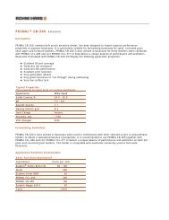
<strong>CVD</strong> ZINC SULFIDE<br />
Application<br />
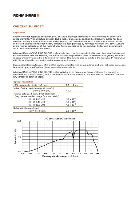
<strong>Chemical</strong>ly vapor deposited zinc sulfide (<strong>CVD</strong> ZnS) is the low lost alternative for infrared windows, domes and<br />
optical elements. With a fracture strength double that of zinc selenide and high hardness, zinc sulfide has been<br />
used successfully in many military applications requiring mechanical resistance to hostile environments. Missile<br />
domes and external windows for military aircraft have been produced by Advanced Materials’ <strong>CVD</strong> ZINC SULFIDE<br />
as the mechanical features of this material allow for high resistance to rain and dust. Its low cost also makes it<br />
attractive for commercial applications.<br />
Advanced Materials’ <strong>CVD</strong> ZINC SULFIDE is chemically inert, non-hygroscopic, highly pure, theoretically dense, and<br />
easily machined. Like zinc selenide, zinc sulfide displays a high level of index of refraction homogeneity and offers<br />
imaging uniformity across the 8-12 micron waveband. This material also transmits in the mid-wave IR region, but<br />
with higher absorption and scatter as the wavenumber increases.<br />
Custom diameters, rectangles, CNC-profiled blanks, generated lens blanks, prisms, and near-net shape domes can<br />
be made to your specifications. Sheet material is also available.<br />
Advanced Materials’ <strong>CVD</strong> ZINC SULFIDE is also available as an evaporative source material. It is supplied in<br />
specified lump sizes (2-20 mm), which to minimize surface contamination, are hand selected to be free from saw<br />
cut, abraded or polished edges.<br />
Optical Properties<br />
10% transmission limits (t=6 mm) 1.0 - 14 μm<br />
Index of refraction inhomogeneity (Δn/n)<br />
(ppm @ 10.6 μm)
Physical Properties<br />
<strong>The</strong>se properties are typical but do not constitute specifications.<br />
Crystal structure cubic<br />
Grain size (diameter) 2 - 8 μm<br />
Density (g cm -3 @ 298 K)<br />
4.09<br />
Resistivity (Ωcm) ≈10 12<br />
<strong>Chemical</strong> purity (%) 99.996<br />
For dielectric constant data, please request the Dielectric<br />
Properties bulletin.<br />
<strong>The</strong>rmal Properties<br />
Coefficient of <strong>The</strong>rmal Expansion<br />
(K -1 @ 273 K)<br />
(K -1 @ 373 K)<br />
(K -1 6.6 x 10<br />
@ 473 K)<br />
-6<br />
7.3 x 10 -6<br />
7.7 x 10 -6<br />
<strong>The</strong>rmal conductivity<br />
(JK -1 m -1 s -1 @ 298 K) 16.7<br />
Heat capacity (Jg -1 K -1 @ 298 K)<br />
0.469<br />
Maximum operating temperature will depend on the environment.
Indices of Refraction (n) of<br />
<strong>CVD</strong> ZINC SULFIDE 1<br />
as a function of wavelength at room temperature (20°C)<br />
Wavelength<br />
(μm) n<br />
Wavelength<br />
(μm) n<br />
0.42 2.516 7.00 2.232<br />
0.46 2.458 7.40 2.228<br />
0.50 2.419 7.80 2.225<br />
0.54 2.391 8.20 2.221<br />
0.58 2.371 8.60 2.217<br />
0.62 2.355 9.00 2.212<br />
0.66 2.342 9.40 2.208<br />
0.70 2.332 9.80 2.203<br />
0.74 2.323 10.20 2.198<br />
0.78 2.316 10.60 2.192<br />
0.82 2.310 11.00 2.186<br />
0.86 2.305 11.40 2.180<br />
0.90 2.301 11.80 2.173<br />
0.94 2.297 12.20 2.167<br />
0.98 2.294 12.60 2.159<br />
1.00 2.292 13.00 2.152<br />
1.40 2.275 13.40 2.143<br />
1.80 2.267 13.80 2.135<br />
2.20 2.263 14.20 2.126<br />
2.60 2.260 14.60 2.116<br />
3.00 2.257 15.00 2.106<br />
3.40 2.255 15.40 2.095<br />
3.80 2.253 15.80 2.084<br />
4.20 2.251 16.20 2.072<br />
4.60 2.248 16.60 2.059<br />
5.00 2.246 17.00 2.045<br />
5.40 2.244 17.40 2.030<br />
5.80 2.241 17.80 2.015<br />
6.20 2.238 18.20 1.998<br />
6.60 2.235
Transmission, Attenuation, and Absorption of Infrared Materials<br />
<strong>The</strong> discussion below is a simplified introduction to the complex subject of determining the transmission,<br />
attenuation, and absorption coefficients of Advanced Materials’ infrared materials. For a more detailed discussion,<br />
please refer to the many textbooks on optical materials.<br />
Transmission<br />
<strong>The</strong>rmo-optic Coefficient,<br />
<strong>CVD</strong> ZINC SULFIDE 1<br />
dn/dT (10 -5 K -1 )<br />
Wavelength (μm)<br />
Temp ºC 1.15 3.39 10.6<br />
-180 3.5 2.8 2.7<br />
-160 3.7 3.1 3.0<br />
-140 3.8 3.3 3.3<br />
-120 4.0 3.5 3.5<br />
-100 4.1 3.7 3.7<br />
-80 4.2 3.9 3.8<br />
-60 4.3 4.0 3.9<br />
-40 4.4 4.1 4.0<br />
-20 4.5 4.1 4.0<br />
0 4.5 4.2 4.1<br />
20 4.6 4.2 4.1<br />
40 4.6 4.3 4.1<br />
60 4.7 4.3 4.1<br />
80 4.7 4.3 4.1<br />
100 4.7 4.3 4.2<br />
120 4.8 4.4 4.2<br />
140 4.8 4.4 4.3<br />
160 4.9 4.4 4.4<br />
180 4.9 4.5 4.5<br />
200 5.0 4.6 4.7<br />
σ a 0.2 0.2 0.2<br />
a Standard deviation from a third degree polynomial fit.<br />
1 A. Feldman et al, Final Technical Report Feb. 1, 1978 - Sept 30, 1978, National<br />
Bureau of Standards Technical Note 933, 53-54<br />
Mechanical Properties<br />
Hardness Knoop, 50 gm load (kg mm -2 )<br />
Vickers, 1 kg load (kg mm -2 )<br />
200 - 235<br />
230<br />
Flexural Strength (modulus of rupture)<br />
4 pt. loading (psi) 15 x 10 3<br />
4 pt. loading (MPa) 103<br />
Disc Bursting (MPa) 84<br />
Fracture Toughness (critical stress intensity factor, K values)<br />
IC<br />
(MPa√m, Vickers, 1 Kg) 0.8<br />
Young’s Modulus (elastic modulus)<br />
(psi) 10.8 x 10 6<br />
(GPa) 74.5<br />
Poisson’s Ratio 0.29<br />
Rain erosion resistance will depend on the environment.<br />
<strong>CVD</strong> ZINC SELENIDE, <strong>CVD</strong> ZINC SULFIDE, CLEARTRAN, and TUFTRAN materials transmit energy in the<br />
visible and infrared regions of the electromagnetic spectrum.
All objects emit infrared radiation at temperatures above absolute zero. This radiation travels through the<br />
atmosphere as a waveform and is bent or refracted through transmitting media such as Advanced Materials’<br />
infrared materials. Infrared radiation follows many of the same physical laws that govern visible light and is<br />
referred to as light, radiation, or energy.<br />
Infrared external transmittance can be defined as the ratio of energy which emerges from the final surface of an<br />
optical material to the energy which first strikes the optical material. <strong>The</strong> percent transmittance in a plane parallel<br />
plate of an optical material would include the original energy less the amount reflected, scattered, and absorbed.<br />
<strong>The</strong> simplified diagram below shows the effect of reflection, absorption, and scatter on the original energy and<br />
resultant transmission.<br />
To determine the theoretical transmission through an uncoated optical material, an optical designer needs to know<br />
the material’s index of refraction. <strong>The</strong> index of refraction, n, is simply defined as the ratio of the velocity of light in<br />
the material to its velocity in a vacuum (n=1). <strong>The</strong> index is most often measured using a refractometer which<br />
measures the angle of refraction at a given wavelength. From the angle of refraction the index can then be<br />
computed. For <strong>CVD</strong> ZINC SELENIDE, <strong>CVD</strong> ZINC SULFIDE, and CLEARTRAN materials, the indices of refraction are<br />
available from Advanced Materials.<br />
When light originating in air (n ~ 1) is incident on the surface of an optically transparent material, some of the<br />
light is reflected from the surface and some is transmitted into the material. <strong>The</strong> fraction of light reflected is given<br />
by:
Eq. (1)<br />
where θ is the angle of incidence (measured from the normal to the surface) and n is the refractive index of the<br />
material. For normal incidence, i.e., cos θ = 1 and sin θ = 0, Eq. (1) reduces to:<br />
Eq. (2)<br />
This will determine reflection from the first (front) surface only. Before the ray of light can exit from the opposite<br />
side, it undergoes a second reflection from the inside of the second surface. This second reflection also bounces<br />
around and if all of this is added up, the total theoretical external transmittance of a polished, uncoated, plane<br />
parallel plate, taking into account multiple internal reflections, and assuming there is no absorption or scattering<br />
within the material, is:<br />
Eq. (3)<br />
where T is the total theoretical external transmittance, which is the maximum transmission possible for an<br />
max<br />
uncoated window. T is a function of wavelength since n varies with the wavelength of light.<br />
max<br />
Attenuation Coefficient<br />
<strong>The</strong> attenuation coefficient, α, is a measure of the loss in transmission due to absorption and scattering of light in<br />
the optical material. <strong>The</strong> measured transmission T, through an optical window of thickness t, is given by:<br />
Eq. (4)<br />
where R is defined in Eq. (2) and a is the attenuation coefficient which has units of reciprocal length, i.e., cm -1 . A<br />
less precise, but more commonly used formula is:<br />
Eq. (5)<br />
For example, if α = 0.1 cm -1 , t = 1 cm and R = 0.15, then T = 0.66 using Eq. (4) and T = 0.65 using Eq. (5).<br />
Since most commercially available conventional IR spectrophotometers have an accuracy of ± 1% for transmission<br />
measurements, in most cases Eq. (5) would be adequate to calculate attenuation coefficients from transmission<br />
data provided T < T . When T ≈ T Fourier Transform IR (FTIR) spectrometers can be used to determine α.<br />
max max<br />
FTIR spectrometers typically can achieve transmission accuracies of better than 0.1 %.<br />
Absorption Coefficient<br />
<strong>The</strong> most widely adopted method for measuring low level optical absorption losses in the infrared is adiabatic laser<br />
calorimetry. <strong>The</strong>rmocouples are attached to the sample periphery and, for a given incident laser power, the<br />
thermal rise and decay as a function of laser irradiation is recorded. <strong>The</strong> magnitude or rate of thermal rise in the<br />
sample is proportional to the absorption coefficient of the sample (both surface and bulk absorption). If the<br />
absorption coefficient of the material to be tested is small, then the following equation can be used to determine<br />
the absorption of the sample:<br />
Eq. (6)<br />
Here n = index of refraction, m = mass of the sample, c = heat capacity, Pt = power transmitted,<br />
(dT Gain /dt) T = slope of the rising part of the temperature vs. time curve at the temperature
= absolute value of the slope of the falling part of the temperature vs. time curve at<br />
a temperature T, and ß = fraction of the power absorbed by the sample.<br />
For a well designed calorimeter, the sample will be sufficiently thermally isolated so that |dT /dt| is small<br />
Loss T<br />
compared to (dT /dt) . This is accomplished by using a suitable sample holder and placing the sample in a<br />
Gain T<br />
vacuum. Care must be taken during measurements to ensure that no laser radiation hits the thermocouples<br />
directly. <strong>The</strong>refore, provisions must be taken to terminate (absorb) the reflected (Fresnel) light from the sample<br />
surfaces. This is usually accomplished by placing the sample to be measured at an angle (
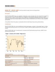
over two frequency ranges: 0.1 and 10.0 GHz, and 9.0 to 18 GHz. <strong>The</strong> high frequency data is good only below 15<br />
GHz. <strong>The</strong> results (including teflon calibration) are given in Figures 12-31.<br />
References:<br />
1. R.L. Taylor, R.F. Donadio, J.A. Fuller, T.S. Taylor and G.N. Hill, “ Development of a Dual Infrared and<br />
Millimeter-Wave Aperature Antenna,” work performed under Boeing Aerospace Co., P.O. CH6411,<br />
<strong>CVD</strong> TR - 025, Oct. 1983.<br />
2. J.A. Fuller, T.S. Taylor, T.B. Elf and G.N. Hill, “Dielectric Properties of Ceramics for Millimeter-Wave Tubes,”<br />
Contract No. F33615-82-C-1718, AFWAL-TR-84-1005, Feb. 1984.<br />
3. Questions should be referred to Mr. Brian Kent, AFWAL/AAWP-3, E-O Observables Group, Phone No.<br />
(513) 255-4465/5076.<br />
<strong>The</strong> measurements included in this document were not made directly by Advanced Materials, and questions concerning experimental detail,<br />
accuracy, etc., should be addressed to the specific performing organization.<br />
Safe Handling Information<br />
<strong>CVD</strong> ZINC SELENIDE and <strong>CVD</strong> ZINC SULFIDE do not present any chemical hazard in their finished form; however,<br />
their fabrication could potentially lead to generation of hazardous materials if necessary precautions are not taken.<br />
<strong>The</strong> hazards associated with the fabrication process depend upon the specific operation; the workpiece; the<br />
abrasive system in use; and the chemical nature of any cooling and/or suspension agents added to the process<br />
water. Grinding of these materials could potentially generate zinc selenide (ZnSe), zinc sulfide (ZnS), zinc oxides<br />
(dust or fume). Loose abrasives used in the lapping and polishing of ZnSe and ZnS may contribute to airborne<br />
contamination of the work area. Wet grinding/polishing is a commonly recommended practice to minimize airborne<br />
particulates, as well as to keep the workpiece surface cool.<br />
<strong>The</strong>se materials are sensitive to high temperature. For ZnS and ZnSe, oxidation and decomposition will occur at<br />
temperature above 200°C in oxidizing atmosphere (e.g., air, oxygen, etc...) and sublimation will occur at<br />
temperature greater than about 500°C. Treatment of our lenses under elevated temperatures must be properly<br />
controlled to prevent decomposition.<br />
<strong>CVD</strong> ZINC SELENIDE and <strong>CVD</strong> ZINC SULFIDE are incompatible with strong acids and strong bases. Cleaning of<br />
these materials using incompatible solvents will result in decomposition with the release of toxic gases such as<br />
hydrogen selenide and hydrogen sulfide.<br />
Controls<br />
Ventilation: If zinc selenide or zinc sulfide are machined, ground or polished, they should be done wet to<br />
suppress dust generation. <strong>The</strong> use of water on grinding operations, however, may not eliminate the need for<br />
ventilation control as water droplets can aerosolize or evaporate, leaving respirable airborne particles. Engineering<br />
controls such as local exhaust ventilation may be necessary, depending upon the degree of airborne particles<br />
being released from the operation.<br />
Personal protective equipment: Due to the possibility of dusts and fumes being generated during the<br />
fabrication of these materials, the following personal protective equipment is recommended; depending on the<br />
degree of exposure.<br />
� <strong>Chemical</strong> goggles, splash shields, or safety glasses to protect eyes<br />
� Rubber gloves<br />
� NIOSH-approved respirator, approved for toxic dusts, mists and fumes<br />
� Eye wash and safety shower stations available in case of eye or skin contact<br />
Care must be taken to maintain all personal protective equipment in a clean and sanitary manner. Food and<br />
beverages should be kept away from areas where zinc selenide and zinc sulfide dust may be present. Hands<br />
should be thoroughly washed before eating to prevent ingestion. Broken pieces of these materials should be<br />
treated like glass, because the material is brittle and forms sharp edges when broken.
<strong>CVD</strong> ZINC SELENIDE, <strong>CVD</strong> ZINC SULFIDE, CLEARTRAN, and TUFTRAN are trademarks of Rohm and Haas <strong>Company</strong>.<br />
<strong>The</strong>se suggestions and data are based on information we believe to be reliable. <strong>The</strong>y are offered in good faith, but without guarantee, as<br />
conditions and methods of use of our products are beyond our control.<br />
We recommend that the prospective user determine the suitability of our materials and suggestions before adopting them on a commercial<br />
scale.<br />
Suggestions for uses of our products or the inclusion of descriptive material from patents and the citation of specific patents in this<br />
publication should not be understood as recommending the use of our products in violation of any patent or as permission or license to use<br />
any patents of the Rohm and Haas <strong>Company</strong>.<br />
©Rohm and Haas, 2008 All rights reserved. May 2000