Technical Specifications - Gammex RMI
Technical Specifications - Gammex RMI
Technical Specifications - Gammex RMI

You also want an ePaper? Increase the reach of your titles
YUMPU automatically turns print PDFs into web optimized ePapers that Google loves.
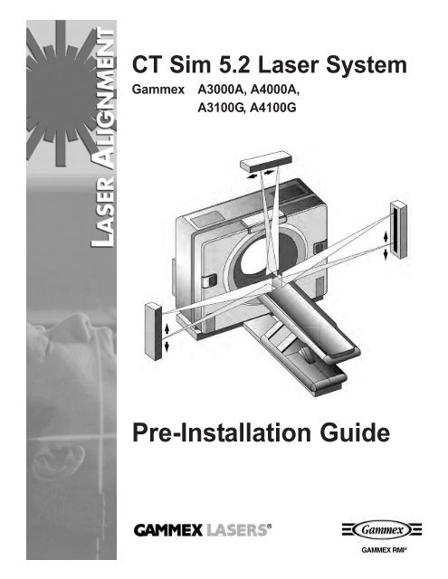
CT Sim 5.2 Laser System<br />
<strong>Gammex</strong> A3000A, A4000A,<br />
A3100G, A4100G<br />
Pre-Installation Guide<br />
GAMMEX <strong>RMI</strong> ®
Table of Contents<br />
1. Introduction...................................................................................... 1<br />
2. Installation Planning Considerations.............................................. 1<br />
3. Room Preparation .......................................................................... 2<br />
4. Considerations for Angled Walls .................................................... 4<br />
5. Electrical and Network Requirements ............................................ 5<br />
6. <strong>Technical</strong> <strong>Specifications</strong> - Red Laser Systems .............................. 7<br />
7. <strong>Technical</strong> <strong>Specifications</strong> - Green Laser Systems ........................... 8<br />
8. <strong>Technical</strong> Assistance and Warranty Information ............................. 9<br />
HARDWARE REQUIREMENTS<br />
The CT Sim 5.2 software has been validated using the computer<br />
and flat screen monitor normally provided with the system. If<br />
<strong>Gammex</strong> supplied computer and monitor are not used, <strong>Gammex</strong><br />
cannot guaantee the functionality and performance of the CT Sim<br />
5.2 Software.<br />
If the computer <strong>Gammex</strong> normally supplied is not used, the<br />
following minimum requirements must be met:<br />
Minimum Requirements, non-<strong>Gammex</strong> supplied Computer<br />
Microsoft Windows 2000 operating system<br />
Intel Pentium-based 1 GHz microprocessor<br />
1 GB free hard drive space<br />
128 MB RAM<br />
Network Interface card 10/100<br />
CD-ROM Drive<br />
256 color 800 x 600 display adapter<br />
2 Serial/Com Ports<br />
It is very important that only the operating system and the<br />
<strong>Gammex</strong> 5.2 Software is installed on the computer. <strong>Gammex</strong><br />
recommends Dell computers. The functionality and performance of<br />
any system not using the computer normally supplied by <strong>Gammex</strong><br />
must be verified by the assembler of the system.
1. Introduction<br />
PRODUCT DESCRIPTION<br />
The <strong>Gammex</strong> CT Sim Laser System consists of one to several<br />
moveable crosshair lasers (the actual number of lasers depends<br />
upon the laser system), a handheld pendant keypad, a power/control<br />
box, and a PC controller, which are operated by the CT Sim 5.2<br />
software. These lasers define the planes in the CT Simulator room.<br />
A calibration phantom is also included.<br />
A3000A System<br />
This red laser system consists of a moveable ceiling laser,<br />
defining the X plane, and two moveable side wall-mounted lasers,<br />
defining the Z plane.<br />
A4000A System<br />
This red laser system consists of a moveable ceiling laser,<br />
defining the X plane, and two side wall-mounted fixed lasers.<br />
A3100G System<br />
This green laser system consists of a moveable ceiling laser,<br />
defining the X plane, and two moveable side wall-mounted lasers,<br />
defining the Z plane.<br />
A4100G System<br />
This green laser system consists of a moveable ceiling laser,<br />
defining the X plane, and two side wall-mounted fixed lasers.<br />
2. Installation Planning Considerations<br />
<strong>Gammex</strong> laser alignment systems provide an accurate, repeatable<br />
optical aid for patient positioning. Proper room preparation ensures<br />
precision, maximizes the alignment accuracy and expedites the<br />
installation.<br />
This pre-installation guide presents the preferred methods for stable<br />
mounting of <strong>Gammex</strong> laser alignment systems. These techniques<br />
should be used for all new construction and can be used with existing<br />
rooms. With new construction, it is essential that these requirements<br />
are incorporated into the room plans as early as possible. For<br />
existing rooms where optimal methods cannot be used, alternate<br />
methods are described. All of the procedures focus on providing<br />
stability for the laser system, since even a slight motion or shift can<br />
degrade performance.<br />
Additional technical support is available from <strong>Gammex</strong> <strong>RMI</strong> Service<br />
Representatives, who are available to work with facility planners,<br />
architects and hospital personnel throughout the planning and<br />
installation process. <strong>Gammex</strong> <strong>RMI</strong> can be contacted at 1-800-232-<br />
9699 or 1-608-828-7000.<br />
NOTE: These lasers allow for direct mounting on angled<br />
walls without the use of unsightly and potentially unstable<br />
wall brackets. In cases where the walls are not accessible we<br />
offer stable laser stanchion systems to meet every need.<br />
Installation Planning Considerations<br />
Pre-Installation Guide<br />
1
CT Sim Laser Alignment Systems<br />
3. Room Preparation<br />
The primary concern for laser accuracy is stability. If stability is<br />
compromised, it will result in inferior performance. In all cases, it is<br />
important that the mounting surfaces are flat. Concrete subwalls<br />
provide the optimum mounting surface. However, this is not available<br />
in most CT rooms. Adding an aluminum/steel plate is needed in most<br />
cases.<br />
If architectural drawings are available use them to determine the<br />
isocenter and plate location.<br />
For drop ceilings, please do not install the ceiling tiles until installation<br />
is complete. Ceiling tile support runners should not cross over or<br />
obstruct the laser. A minimum of four inches clearance is needed for<br />
cover removal.<br />
MOUNTING TO CONCRETE<br />
No aluminum or steel plate is needed. The minimum space required<br />
is 54 x 15 in. (137 x 38 cm) (H, W) of bare concrete. The center of<br />
the concrete space should be placed at CT isocenter height, 600 mm in<br />
front of the CT scan plane. See figures 1 and 2. Use the mounting<br />
hardware provided.<br />
MOUNTING TO UNISTRUT<br />
A steel, or preferably aluminum mounting plate, is required with<br />
minimum dimensions of 54 x 20 x 3/8 in. (137 x 50.8 x 0.95 cm)<br />
(H,W,D). The plate thickness should not exceed 5/8 inch (1.6 cm).<br />
The center of the mounting plate should be placed at CT isocenter<br />
height, 600 mm in front of the CT scan plane. See figures 1 and 2.<br />
MOUNTING TO EXISTING WALLS<br />
An aluminum mounting plate of sufficient width to span three studs is<br />
required (minimum 20 in.) A steel plate may be substituted with wood<br />
stud construction, but should not be used with metal studs. The plate<br />
should have minimum dimensions of 54" high by 3/8" thick (137 x<br />
0.95). Thickness should not exceed 1/2 in. (1.27 cm). The center of<br />
the plate should be placed at CT isocenter height, 600 mm in front of<br />
the CT scan plane (See figures 1 and 2). Use 3 3/4 in. Number 12<br />
hardened steel deck screws to mount the aluminum plate to the wall<br />
studs (see the deck screw mounting configuration at right).<br />
NOTE: A solid mounting to the studs is required. Mounting<br />
plates must not be attached directly to drywall. Do NOT cover<br />
the plates with drywall after installation.<br />
The wall mounting location must be level to provide a planar surface<br />
for the laser and to allow the laser beams to project perpendicularly to<br />
the isocenter height but located 600 mm out of the scan plane. In<br />
some cases a stand off bracket may be required for the ceiling laser.<br />
This plate can be mounted 3.5 in. (8.9 cm) above the finished ceiling<br />
for flush mount lasers. If room is not available above the ceiling, the<br />
plate can be mounted flush with the ceiling or just below.<br />
NOTE: Walls at an angle to the CT scan plane require special<br />
consideration. Please see Figure 2 and Page 4.<br />
2<br />
Room Preparation<br />
Metal Plate<br />
Wall Studs<br />
Deck Screw Mounting<br />
Configuration<br />
54"
Control Room<br />
Control Room<br />
Mounting Plate<br />
Ceiling Plate<br />
String or<br />
Laser line<br />
Mounting Plate<br />
600 mm<br />
Figure 1: Side Wall Installation<br />
Mounting Plate<br />
Plate Shift Direction<br />
Ceiling Plate<br />
Plate Shift Direction<br />
Mounting Plate<br />
String or<br />
Laser line<br />
Figure 2: Angled Wall Installation<br />
Room Preparation<br />
Pre-Installation Guide<br />
Isocenter<br />
Isocenter<br />
600 mm<br />
3
CT Sim Laser Alignment Systems<br />
4. Considerations for Angled Walls<br />
The chart below is to help determine the plate shift needed so that<br />
the mounting plate will be centered properly. Plate shifts should<br />
always be towards the smaller angle. See figure 2 on page 3 and<br />
figure 3 on this page.<br />
Walls angled 80-90° will not need a plate shift<br />
Walls angled 75° will need a 1 /2" plate shift<br />
Walls angled 70° will need a 1" plate shift<br />
Walls angled 65° will need a 11 /4" plate shift<br />
Walls angled 60° will need a 111 /16" plate shift<br />
Walls angled 55° will need a 2" plate shift<br />
Walls angled 50° will need a 21 /2" plate shift<br />
Walls angled 45° will need a 3" plate shift<br />
Figure 3: This<br />
illustration shows how<br />
to determine the offset<br />
needed for mounting<br />
templates on angled<br />
walls. Place a protractor<br />
or similar device where<br />
the string or laser line<br />
contacts the wall to<br />
measure the wall’s angle<br />
to the scan plane.<br />
4<br />
Couch<br />
Mounting Plate<br />
String or<br />
Laser Line<br />
Considerations for Angled Walls<br />
600 mm<br />
Direction of Offset<br />
CT<br />
Scan<br />
Plane<br />
Isocenter<br />
Mounting Plate
Electrical and Network Requirements<br />
Pre-Installation Guide<br />
5. Electrical and Network Requirements<br />
Note: There should not be ground potential differences<br />
between the PC ground and the controller box ground.<br />
If so, equipotential grounding or additional protective<br />
grounding must be provided.<br />
A separate, 1 inch minimum metal conduit, raceway or equivalent<br />
should be placed between the three lasers and the control room<br />
where the computer will be located. Three separate 110/220 volt<br />
outlets will be needed to power the computer, monitor and controller<br />
box in the control room. See Figure 4<br />
An IP address/default gateway and sub net mask should be<br />
available to <strong>Gammex</strong> at the time of Installation.<br />
A live network connection along with network cable should be<br />
provided.<br />
The system can be wired as a branch or series circuit.<br />
See Figure 5 on page 6<br />
Figure 4: Conduit Wiring Diagram<br />
Junction Boxes for Z1 and Z2<br />
should be at the bottom or bottom<br />
left of the laser. For the X laser,<br />
mount the junction box on the left<br />
when viewed from the foot of the<br />
treatment couch.<br />
5
CT CT Sim Sim Laser Laser Alignment Alignment Systems Systems<br />
6<br />
Figure 5: CT Sim Wiring Diagrams<br />
Electrical and Network Requirements
<strong>Technical</strong> <strong>Specifications</strong> - Red<br />
Installation Guide<br />
6. <strong>Technical</strong> <strong>Specifications</strong><br />
A3000A and A4000A Red Laser Systems<br />
POWER REQUIREMENTS<br />
Laser Unit (Moving Laser, Power Module Input)<br />
Voltage: .............. 100-240 V~(auto-select)<br />
Current:............... 4.5A Max<br />
Frequency:.......... 60/50 Hz<br />
Laser Unit (Probe+ - A4000A only)<br />
Voltage: .............. 12 VDC<br />
Current:............... 300 mA<br />
Power: ................ 3.6 W<br />
LASER SPECIFICATIONS<br />
Less than 1.0 mW (each beam) Laser Class II<br />
Wavelength:........ 6350 Å (635nm) visible red<br />
ENVIRONMENTAL (SHIPPING AND STORAGE CONDITIONS)<br />
Temperature:<br />
Systems should be stored and shipped<br />
between -20°C to 70°C (-4°F and 150° F).<br />
Humidity:<br />
The operating and non-operating relative humidity<br />
(non-condensing) range is 10% and 95%.<br />
PHYSICAL DIMENSIONS<br />
Laser Unit (Moving Lasers): ..................... 117 x 21 x 9 cm (HWD)<br />
Laser Unit (Probe+; A4000A only): .......... 17.3 x 14 x 8 cm (HWD)<br />
Power Module: ......................................... 42 x 21 x 9 cm (HWD)<br />
WEIGHT<br />
Laser Unit (Moving Lasers): ..................... 11.6 kg<br />
Laser Unit (Probe+; A4000A only): .......... 1.8 kg<br />
Power Module: ......................................... 3.3 kg<br />
Communications: ...................................... Two RS-232 port<br />
DISPOSAL<br />
These units should be disposed of according to national<br />
laws and regulations. Recycle components as required.<br />
EMC INFLUENCES<br />
These units were tested under the IEC 601-1-2 standard and<br />
they should not be adversely affected by other outside influences.<br />
LEAKAGE REQUIREMENTS<br />
The personal computer (PC) must be plugged into a different and<br />
properly grounded branch circuit other than the power supply module<br />
for the lasers. This prevents the possibility of leakage currents in the<br />
event of a fault in the protective earth connection.<br />
7
CT Sim Laser Alignment Systems<br />
7. <strong>Technical</strong> <strong>Specifications</strong><br />
A3100G and A4100G Green Laser Systems<br />
POWER REQUIREMENTS<br />
Laser Unit (Moving Laser, Power Module Input)<br />
Voltage: .............. 100-240 V~(auto-select)<br />
Current:............... 3.0A Max<br />
Frequency:.......... 60/50 Hz<br />
Laser Unit (ProbeG - A4100G only)<br />
Voltage: .............. 100-240 VAC<br />
Current:............... 0.4 A<br />
Frequency:.......... 60/50 Hz<br />
LASER SPECIFICATIONS<br />
Less than 1.0 mW (each beam) Laser Class II<br />
Wavelength:........ 5320 Å (532nm) visible green<br />
ENVIRONMENTAL (SHIPPING AND STORAGE CONDITIONS)<br />
Temperature:<br />
Systems should be stored and shipped<br />
between -20°C to 70°C (-4°F and 150° F).<br />
Humidity:<br />
The operating and non-operating relative humidity<br />
(non-condensing) range is 10% and 95%.<br />
PHYSICAL DIMENSIONS<br />
Laser Unit (Moving Lasers): ..................... 117 x 21 x 9 cm (HWD)<br />
Laser Unit (ProbeG; A4100G only): ......... 27 x 14 x 8 cm (HWD)<br />
Power Module: ......................................... 42 x 21 x 9 cm (HWD)<br />
WEIGHT<br />
Laser Unit (Moving Lasers): ..................... 9.5 kg<br />
Laser Unit (ProbeG; A4100G only): ......... 3.2 kg<br />
Power Module: ......................................... 3.3 kg<br />
Communications: ...................................... Two RS-232 port<br />
DISPOSAL<br />
These units should be disposed of according to national<br />
laws and regulations. Recycle components as required.<br />
EMC INFLUENCES<br />
These units were tested under the IEC 601-1-2 standard and<br />
they should not be adversely affected by other outside influences.<br />
LEAKAGE REQUIREMENTS<br />
The personal computer (PC) must be plugged into a different and<br />
properly grounded branch circuit other than the power supply module<br />
for the lasers. This prevents the possibility of leakage currents in the<br />
event of a fault in the protective earth connection.<br />
8<br />
<strong>Technical</strong> <strong>Specifications</strong> - Green
8. <strong>Technical</strong> Support<br />
<strong>Technical</strong> support is available from <strong>Gammex</strong> <strong>RMI</strong> Service<br />
Representatives who are available to work with facility planners,<br />
architects and hospital personnel throughout the planning and<br />
installation process. Contact the <strong>Gammex</strong> <strong>RMI</strong> Service<br />
department at 1-800-232-9699.<br />
Product Warranty<br />
<strong>Gammex</strong> Inc. warrants its patient positioning equipment to be free<br />
from defects in materials and workmanship under normal use and<br />
service for 1 year from the date of shipment. The sole obligation of<br />
<strong>Gammex</strong> Inc. under this warranty is to repair or replace without<br />
charge or to refund the purchase price, at the option of <strong>Gammex</strong> Inc.,<br />
of any parts which its examination shall have disclosed to be<br />
defective, provided that Buyer shall have given to <strong>Gammex</strong> Inc., a<br />
written notice of the claimed defect no later than 7 days after the end<br />
of the warranty period (one (1) year of the date of shipment of such<br />
equipment to Buyer). At the request of <strong>Gammex</strong> Inc., Buyer, at its<br />
expense, shall return the claimed defective part to <strong>Gammex</strong> Inc.<br />
THIS CLASS II LASER PRODUCT COMPLIES<br />
WITH DHHS REQUIREMENTS PURSUANT TO<br />
21 CFR, SUB-CHAPTER J.<br />
DISCLAIMER OF OTHER WARRANTIES<br />
Pre-Installation Installation Guide Guide<br />
The aforesaid warranty rights are buyer's exclusive remedies and are in lieu of any<br />
other remedies, obligations, or rights, including, without limitation, any other warranties,<br />
expressed or implied (e.g., implied warranties of merchantability or fitness for a<br />
particular purpose). Under no circumstances shall <strong>Gammex</strong> Inc. be liable for any<br />
incidental, indirect, special or consequential damages or for any other loss, damage,<br />
penalty or expense of any kind, including, without limitation, loss of profits or overhead,<br />
reimbursement, personal injury or property damage. The aforesaid warranty obligation<br />
of <strong>Gammex</strong> Inc. constitutes its sole liability, and under no circumstances, shall the<br />
maximum liability of <strong>Gammex</strong> Inc., under any legal theory(e.g., contract, warranty,<br />
negligence, promisory estoppel, strict liability, misrepresentation, tort) and for any<br />
reason whatsoever(e.g., defect, delay or otherwise) exceed the purchase price of the<br />
defective part regardless whether the claim is asserted by buyer or any other person or<br />
entity. The liabilities of <strong>Gammex</strong> Inc. as above set forth, shall not be extended because<br />
of advice given by it in connection with the design, installation or use of the equipment<br />
or parts therefore.<br />
<strong>Technical</strong> Support and Warranty Information<br />
9
CT Sim Laser Alignment Systems<br />
10<br />
Notes<br />
Notes
Notes<br />
Pre-Installation Guide<br />
Notes<br />
11
CT Sim Laser Alignment Systems<br />
About GAMMEX <strong>RMI</strong>…<br />
<strong>Gammex</strong> <strong>RMI</strong> has been a leader in the manufacture and distribution<br />
of Quality Control devices for medical imaging and radiation therapy,<br />
including laser alignment systems, for over 35 years. <strong>Gammex</strong> was<br />
incorporated in 1969 as a manufacturer of laser alignment devices<br />
for use in medical imaging and oncology treatment. The acquisition<br />
of <strong>RMI</strong> in 1987 gave the company the ability to expand into the<br />
manufacture of quality control equipment for ultrasound, diagnostic<br />
radiology and mammography.<br />
<strong>Gammex</strong> <strong>RMI</strong> research and development team has patented a<br />
number of devices over the years. These include numerous patents<br />
on laser technology, optical chains, kV detecting devices and<br />
diagnostic phantoms. There are over 25 patents issued to <strong>Gammex</strong><br />
<strong>RMI</strong>.<br />
<strong>Gammex</strong> <strong>RMI</strong> corporate headquarters are located in Middleton, WI<br />
with production facilities in that location as well is in Milwaukee, WI<br />
and Benicia, CA. European and other overseas markets are<br />
serviced by <strong>Gammex</strong> <strong>RMI</strong>, Ltd. in Nottingham, UK and <strong>Gammex</strong><br />
<strong>RMI</strong> GmbH in Bad Münstereifel, Germany.<br />
With extensive domestic and international experience, ISO-9001 and<br />
EN 4600 certified <strong>Gammex</strong> <strong>RMI</strong> continues to explore new realms of<br />
technology while keeping its focus on you and your patients.<br />
When there is little room for error, choose the wide range of<br />
<strong>Gammex</strong> <strong>RMI</strong> quality assurance products!<br />
12
Product Ordering Information<br />
and Customer Service<br />
<strong>Gammex</strong> is committed to satisfying our customers’ needs. If you have any<br />
questions, comments or suggestions regarding our products and service, please<br />
call or fax us. Please contact a GAMMEX dealer or representative for a<br />
quotation or for a detailed description of our ordering policies, warranties,<br />
delivery policy, conditions of sale, damaged goods policy, and returned goods<br />
policy.<br />
In the United States, Sales Department hours are:<br />
7:00 a.m. through 6:00 p.m. (Central Time).<br />
SALES/CUSTOMER SERVICE: 608-828-7000<br />
TOLL FREE (U.S. and Canada only): 800-426-6391<br />
FAX: 608-828-7500<br />
Sales e-mail: sales@gammex.com<br />
In the United States, Service Department hours are:<br />
7:00 a.m. through 5:00 p.m. (Central Time).<br />
SERVICE DEPARTMENT: 608-828-7000<br />
TOLL FREE (U.S. and Canada only): 800-232-9699<br />
FAX: 608-831-0964<br />
Service e-mail: support@gammex.com<br />
GAMMEX, Inc.<br />
2500 W. Beltline Hwy<br />
P.O. Box 620327<br />
Middleton, WI 53562-0327 USA<br />
On the internet at: www.gammex.com<br />
VISA, MasterCard and American Express accepted.<br />
All products and specifications are subject to change without notice.<br />
© 2003 GAMMEX-<strong>RMI</strong>. All rights reserved.<br />
Printed in U.S.A. P/N 007084-00-01
GAMMEX <strong>RMI</strong><br />
P.O. Box 620327<br />
Middleton, WI 53562-0327 USA<br />
1-800-GAMMEX 1 (426-6391)<br />
1-608-828-7000<br />
Fax: 1-608-828-7500<br />
www.gammex.com<br />
e-mail: sales@gammex.com<br />
GAMMEX-<strong>RMI</strong> LTD<br />
Karlsruhe House<br />
18 Queens Bridge Road<br />
Nottingham NG2 1NB, England<br />
(+44) (0) 115 985-0808<br />
Fax: (+44) (0) 115-985-0344<br />
e-mail: sales@gammex-rmi.co.uk<br />
GAMMEX-<strong>RMI</strong> GMBH<br />
Odesheimer Weg 17<br />
53902 Bad Münstereifel<br />
Germany<br />
(+49) (0) 2257-823<br />
Fax: (+49) (0) 2257-1692<br />
e-mail: <strong>Gammex</strong>-<strong>RMI</strong>GmbH@t-online.de<br />
GAMMEX <strong>RMI</strong> ®