FAS366U Fast Architecture SCSI Processor
FAS366U Fast Architecture SCSI Processor
FAS366U Fast Architecture SCSI Processor

Create successful ePaper yourself
Turn your PDF publications into a flip-book with our unique Google optimized e-Paper software.
QLogic Corporation<br />
�������<br />
���� ������������ ���� ���������<br />
Features<br />
� Compliance with ANSI draft <strong>Fast</strong>–20 standard<br />
� Compliance with ANSI X3T10/855D <strong>SCSI</strong>–3<br />
parallel interface (SPI) standard<br />
� Compliance with ANSI <strong>SCSI</strong> configured<br />
automatically (SCAM) protocol levels 1 and 2<br />
� Sustained <strong>SCSI</strong> data transfer rates of up to:<br />
� 40 Mbytes/sec synchronous (ultra and wide<br />
<strong>SCSI</strong>)<br />
� 14 Mbytes/sec asynchronous (wide <strong>SCSI</strong>)<br />
� Synchronous DMA timing; DMA speed of<br />
50 Mbytes/sec<br />
� REQ and ACK programmable assertion and<br />
deassertion control<br />
DB BUS<br />
PAD BUS<br />
COMMAND<br />
RECOMMAND<br />
COUNTER<br />
TRANSFER<br />
COUNT<br />
SEL/RESEL<br />
BUS ID<br />
SEL/RESEL<br />
TIMEOUT<br />
SYNC PERIOD<br />
SYNC OFFSET/<br />
SYNC ASSERT/<br />
SYNC DEASSERT<br />
CLOCK<br />
CONVERSION<br />
CONFIGURATION<br />
TEST (SCAM)<br />
FIFO<br />
���� �����<br />
SEQUENCERS<br />
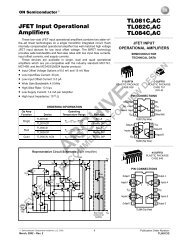
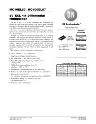
Figure 1. <strong>FAS366U</strong> Block Diagram<br />
� Support for hot plugging<br />
� Target and initiator block transfer sequences<br />
� Bus idle timer<br />
� Split–bus architecture<br />
� Pipelined command structure<br />
� On–chip, single–ended <strong>SCSI</strong> transceivers<br />
(48–mA drivers)<br />
� Initiator and target roles<br />
� Active negation<br />
� 16–bit recommand counter<br />
� Differential mode<br />
� <strong>SCSI</strong> bus reset watchdog timer<br />
BLOCK<br />
REGISTERS<br />
TRANSFER<br />
COUNTER<br />
INTERRUPT<br />
SEQUENCE<br />
STEP<br />
<strong>SCSI</strong><br />
DATA<br />
PARITY (2)<br />
DATA (16)<br />
<strong>SCSI</strong><br />
CONTROL<br />
53366–580–01 B <strong>FAS366U</strong> 1<br />
STATUS
QLogic Corporation<br />
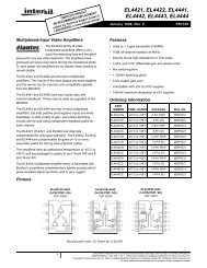
Product Description<br />
The <strong>FAS366U</strong> is a new addition to the QLogic fast<br />
architecture <strong>SCSI</strong> processor (FAS) chip family. The<br />
<strong>FAS366U</strong> supports advanced <strong>SCSI</strong>–3 options including<br />
ultra <strong>SCSI</strong> synchronous transfers. Also included is the<br />
advanced SCAM level 2 <strong>SCSI</strong> controller core.<br />
The <strong>FAS366U</strong> is a single–chip controller for use in<br />
host and peripheral applications. It is firmware and<br />
pin–out compatible with the QLogic FAS366 chip. The<br />
<strong>FAS366U</strong> block diagram is shown in figure 1.<br />
The <strong>FAS366U</strong> implements QLogic’s new <strong>SCSI</strong><br />
target and initiator block transfer sequences. The block<br />
sequences reduce firmware overhead and are composed<br />
of the following new commands: Target Block<br />
Sequence (including the bus idle timer), Initiator Block<br />
Sequence, Load/Unload Block Registers sequences,<br />
Abort Block Sequence, and Disconnect Abort Block<br />
Sequence.<br />
The <strong>FAS366U</strong> supports both single–ended and<br />
differential mode <strong>SCSI</strong> operations and operates in<br />
initiator and target roles. The <strong>FAS366U</strong> has been<br />
optimized for interaction with a DMA controller and<br />
the controlling microprocessor.<br />
The versatile split–bus architecture supports various<br />
microprocessor and DMA bus configurations. A<br />
separate 8–bit microprocessor bus (PAD) provides<br />
access to all internal registers, and a 16–bit DMA bus<br />
(DB) provides a path for DMA transfers through the<br />
FIFO. Each bus is protected by a parity bit (byte–wide<br />
parity) to improve data integrity. During data transfer,<br />
the microprocessor has instant access to status and has<br />
the ability to execute commands.<br />
SCAM Implementation<br />
The <strong>FAS366U</strong> supports levels 1 and 2 of the SCAM<br />
protocol. Refer to the latest revision of X3T10/855D,<br />
Annex B. The SCAM protocol requires direct access<br />
and control over the <strong>SCSI</strong> data bus and several of the<br />
<strong>SCSI</strong> phase and control signals. The majority of the<br />
SCAM protocol can be implemented in firmware at<br />
microprocessor speeds. The following SCAM features<br />
are supported in the hardware:<br />
� Arbitration without an ID<br />
� Slow response to selection with an unconfirmed ID<br />
� Detection of and response to SCAM selection<br />
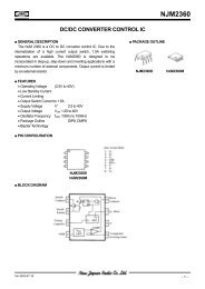
<strong>Fast</strong> DMA Protocol<br />
The fast DMA protocol is required for supporting<br />
the full bandwidth of ultra, wide <strong>SCSI</strong>.<br />
The DREQ signal initiates DMA transfers and runs<br />
asynchronous to the user’s clock. For read operations,<br />
DACK acts as a chip select to enable the <strong>FAS366U</strong><br />
drivers onto the DMA bus. The chip select role of<br />
DACK helps support the burst timing of fast DMA<br />
mode. DACK selects the <strong>FAS366U</strong> after DREQ is<br />
asserted and is removed either after DREQ is deasserted<br />
or when the DMA transfer is paused.<br />
DBRD requests data from the <strong>FAS366U</strong> and DBWR<br />
validates data sent to the <strong>FAS366U</strong>. Data is valid<br />
around the rising (trailing) edge of DBRD or DBWR.<br />
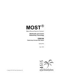
DMA transfers are terminated by deasserting<br />
DREQ. Deassertion of DREQ is triggered by the<br />
leading edge of DBRD or DBWR (see timing<br />
parameter t1 in figures 2 and 3) under any of the<br />
following conditions:<br />
� To prevent FIFO overrun conditions<br />
� To prevent FIFO underrun conditions<br />
� When the required amount of data has been<br />
transferred<br />
When DREQ is deasserted, the <strong>FAS366U</strong> ignores<br />
DBRD and DBWR. Data transfers do not take place<br />
unless DREQ is asserted.<br />
The <strong>FAS366U</strong> does not generate parity on the<br />
incoming DMA bus. Correct parity must always be<br />
supplied with the data.<br />
The DMA interface signals are given in table 1.<br />
DMA timing is given in table 2 and figures 2 and 3.<br />
Table 1. DMA Interface Signals<br />
Active<br />
Level<br />
Description<br />
DREQ ÁÁÁ<br />
O ÁÁÁÁÁ<br />
High The <strong>FAS366U</strong> DMA<br />
request line begins and<br />
ends DMA cycles.<br />
ÁÁÁÁÁÁÁÁ<br />
I Low DACKÁÁÁ<br />
The acknowledge is ÁÁÁÁÁ<br />
used<br />
as a chip select to activate<br />
<strong>FAS366U</strong> drivers and to<br />
acknowledge acceptance of<br />
DREQ.<br />
ÁÁÁ ÁÁÁÁÁÁÁÁ<br />
ÁÁÁÁÁ<br />
ÁÁÁÁÁÁÁÁ<br />
DBRDÁÁÁ ÁÁÁÁÁ<br />
ÁÁÁ I<br />
ÁÁÁ<br />
ÁÁÁ<br />
ÁÁÁÁÁ<br />
Rising edge<br />
ÁÁÁÁÁ<br />
ÁÁÁÁÁ<br />
ÁÁÁÁÁÁÁÁ<br />
The trailing edge accepts<br />
data ÁÁÁÁÁÁÁÁ<br />
from the <strong>FAS366U</strong> for<br />
DMA read ÁÁÁÁÁÁÁÁ<br />
operations.<br />
DBWR ÁÁÁ<br />
I<br />
ÁÁÁ<br />
ÁÁÁ<br />
ÁÁÁÁÁ<br />
Rising<br />
ÁÁÁÁÁ<br />
edge<br />
ÁÁÁÁÁ<br />
ÁÁÁÁÁÁÁÁ<br />
The trailing edge strobes<br />
ÁÁÁÁÁÁÁÁ<br />
data into the <strong>FAS366U</strong><br />
FIFO on DMA write<br />
ÁÁÁÁÁÁÁÁ<br />
operations.<br />
DB15–0 ÁÁÁ<br />
N/A This is the DMA data bus.<br />
ÁÁÁ<br />
ÁÁÁ<br />
PinÁÁÁ<br />
ÁÁÁ<br />
TypeÁÁÁÁÁ<br />
ÁÁÁÁÁ<br />
ÁÁÁÁÁÁÁÁ<br />
ÁÁÁ ÁÁÁÁÁÁÁÁ<br />
ÁÁÁ ÁÁÁÁÁ<br />
ÁÁÁ ÁÁÁÁÁÁÁÁ<br />
ÁÁÁÁÁ ÁÁÁÁÁÁÁÁ<br />
ÁÁÁ ÁÁÁ<br />
ÁÁÁ ÁÁÁÁÁ ÁÁÁÁÁÁÁÁ<br />
ÁÁÁ<br />
ÁÁÁÁÁÁÁÁ<br />
ÁÁÁÁÁÁÁÁ<br />
ÁÁÁ<br />
ÁÁÁ<br />
ÁÁÁ<br />
ÁÁÁ<br />
ÁÁÁ<br />
ÁÁÁ<br />
ÁÁÁ<br />
ÁÁÁ ÁÁÁÁÁ ÁÁÁÁÁÁÁÁ<br />
ÁÁÁ<br />
ÁÁÁ ÁÁÁ<br />
I/OÁÁÁÁÁ<br />
ÁÁÁÁÁ<br />
ÁÁÁÁÁÁÁÁ<br />
ÁÁÁÁÁÁÁÁ<br />
2 <strong>FAS366U</strong> 53366–580–01 B
Table 2. DMA Timing<br />
ÁÁÁÁÁÁÁÁÁÁÁ<br />
Symbol Description<br />
(ns)ÁÁÁÁÁÁ<br />
Minimum Maximum ÁÁÁ<br />
(ns) Note<br />
t1<br />
DBRD/DBWR low to DREQ low<br />
ÁÁÁÁ<br />
ÁÁÁÁÁ<br />
ÁÁÁÁÁ ÁÁÁÁÁÁ ÁÁÁ<br />
ÁÁÁÁ<br />
ÁÁÁÁÁÁÁÁÁÁÁ ÁÁÁÁÁ<br />
ÁÁÁÁÁÁÁÁÁÁÁ<br />
ÁÁÁÁÁ ÁÁÁÁ ÁÁÁÁÁÁÁÁÁÁÁ<br />
ÁÁÁÁÁÁ ÁÁÁ<br />
ÁÁÁÁ<br />
ÁÁÁÁÁÁ<br />
t2<br />
ÁÁÁ<br />
ÁÁÁÁ<br />
ÁÁÁÁÁÁÁÁÁÁÁ<br />
DACK high to DREQ ÁÁÁÁÁ<br />
high<br />
TBD<br />
ÁÁÁÁÁÁÁÁÁÁÁ ÁÁÁÁÁ<br />
ÁÁÁÁÁÁ<br />
ÁÁÁÁÁÁ ÁÁÁ<br />
ÁÁÁ<br />
t3 ÁÁÁÁ<br />
ÁÁÁÁ<br />
ÁÁÁÁÁÁÁÁÁÁÁ<br />
DACK high to DACK ÁÁÁÁÁ<br />
low<br />
40<br />
ÁÁÁÁÁÁÁÁÁÁÁ ÁÁÁÁÁ<br />
ÁÁÁÁÁÁ<br />
ÁÁÁÁÁÁ ÁÁÁ<br />
ÁÁÁÁÁ ÁÁÁ<br />
ÁÁÁÁ<br />
ÁÁÁÁÁÁ ÁÁÁ<br />
tR1 ÁÁÁÁÁÁÁÁÁÁÁ<br />
DACK low to DBRD low<br />
tR2 ÁÁÁÁÁÁÁÁÁÁÁ<br />
DBRD assertion pulse width<br />
tR3 ÁÁÁÁÁÁÁÁÁÁÁ<br />
DBRD deassertion pulse width<br />
ÁÁÁÁÁÁÁÁÁÁÁ ÁÁÁÁÁÁ ÁÁÁ<br />
ÁÁÁÁ<br />
ÁÁÁÁÁ<br />
ÁÁÁÁÁ<br />
ÁÁÁÁ ÁÁÁÁÁÁÁÁÁÁÁ<br />
ÁÁÁÁÁÁ ÁÁÁ<br />
ÁÁÁÁ<br />
ÁÁÁÁÁ ÁÁÁÁÁÁ ÁÁÁ<br />
ÁÁÁÁÁÁ ÁÁÁ<br />
tR4 ÁÁÁÁÁÁÁÁÁÁÁ<br />
DBRD high to DACK high<br />
tR5 ÁÁÁÁÁÁÁÁÁÁÁ<br />
DBRD low to DBRD low cycle<br />
ÁÁÁÁÁÁÁÁÁÁÁ ÁÁÁÁÁÁ<br />
ÁÁÁÁ<br />
ÁÁÁÁÁ<br />
ÁÁÁ<br />
ÁÁÁÁ ÁÁÁÁÁÁÁÁÁÁÁ ÁÁÁÁÁ<br />
ÁÁÁÁÁÁ<br />
ÁÁÁÁÁÁ ÁÁÁ<br />
ÁÁÁÁ<br />
ÁÁÁ<br />
ÁÁÁÁÁÁÁÁÁÁÁ<br />
ÁÁÁÁ<br />
ÁÁÁÁÁ<br />
ÁÁÁÁÁ<br />
ÁÁÁÁÁÁ<br />
ÁÁÁÁÁÁ ÁÁÁ<br />
ÁÁÁÁ<br />
ÁÁÁ<br />
tR6<br />
ÁÁÁÁ<br />
ÁÁÁÁÁÁÁÁÁÁÁ ÁÁÁÁÁ<br />
DACK low to DB15–0<br />
ÁÁÁÁÁ<br />
read<br />
ÁÁÁÁÁÁÁÁÁÁÁ<br />
on<br />
2<br />
ÁÁÁÁÁÁ<br />
ÁÁÁÁÁÁ ÁÁÁ<br />
ÁÁÁ<br />
c<br />
ÁÁÁÁ<br />
tR7<br />
ÁÁÁÁ<br />
ÁÁÁÁÁÁÁÁÁÁÁ<br />
DACK high to DB15–0<br />
ÁÁÁÁÁÁÁÁÁÁÁ<br />
read off<br />
ÁÁÁÁÁ<br />
ÁÁÁÁÁ ÁÁÁÁÁÁ<br />
15<br />
ÁÁÁÁÁÁ<br />
ÁÁÁ<br />
ÁÁÁ<br />
c<br />
ÁÁÁÁ<br />
tR8<br />
ÁÁÁÁ<br />
ÁÁÁÁÁÁÁÁÁÁÁ<br />
DBRD low to DB15–0<br />
ÁÁÁÁÁÁÁÁÁÁÁ<br />
read valid<br />
ÁÁÁÁÁ<br />
ÁÁÁÁÁ ÁÁÁÁÁÁ<br />
15<br />
ÁÁÁÁÁÁ<br />
ÁÁÁ<br />
ÁÁÁ<br />
c<br />
ÁÁÁÁ<br />
ÁÁÁÁÁ ÁÁÁÁÁÁ<br />
ÁÁÁÁÁÁÁÁÁÁÁ<br />
tR9 DBRD low to DB15–0 read<br />
ÁÁÁÁÁ<br />
invalid<br />
ÁÁÁÁÁÁ ÁÁÁÁ<br />
0<br />
ÁÁÁÁÁÁÁÁÁÁÁ<br />
ÁÁÁ<br />
ÁÁÁ c<br />
ÁÁÁÁÁÁ ÁÁÁ<br />
ÁÁÁÁÁ<br />
ÁÁÁÁÁÁÁÁÁÁÁ<br />
ÁÁÁÁ<br />
tW1<br />
tW2<br />
tW3<br />
DACK low to DBWR low<br />
DBWR assertion pulse width<br />
DBWR deassertion pulse width<br />
ÁÁÁÁ<br />
ÁÁÁÁÁÁÁÁÁÁÁ<br />
ÁÁÁÁÁÁÁÁÁÁÁ<br />
ÁÁÁÁÁÁÁÁÁÁÁ<br />
ÁÁÁ<br />
ÁÁÁÁÁ ÁÁÁÁÁÁ<br />
ÁÁÁÁ<br />
ÁÁÁ<br />
ÁÁÁÁÁÁÁÁÁÁÁÁÁÁÁÁÁÁÁÁÁÁÁÁÁÁÁÁÁ<br />
ÁÁÁÁ ÁÁÁÁÁÁÁÁÁÁÁ ÁÁÁÁÁ ÁÁÁÁÁÁ ÁÁÁ<br />
ÁÁÁÁÁÁ<br />
ÁÁÁÁÁ<br />
ÁÁÁÁÁÁÁÁÁÁÁ<br />
ÁÁÁÁ<br />
ÁÁÁÁÁÁÁÁÁÁÁ<br />
tW4 DBWR high to DACK ÁÁÁÁÁ<br />
high ÁÁÁÁÁÁ<br />
tW3 d<br />
ÁÁÁÁÁÁÁÁÁÁÁ<br />
tW5 DBWR low to DBWR low ÁÁÁÁÁ<br />
cycle ÁÁÁÁÁÁ<br />
40<br />
ÁÁÁÁÁÁÁÁÁÁÁ ÁÁÁÁÁÁ<br />
ÁÁÁÁ<br />
ÁÁÁÁÁÁÁÁÁÁÁÁÁÁÁÁ<br />
ÁÁÁÁÁ ÁÁÁÁÁÁÁÁÁ<br />
ÁÁÁ<br />
ÁÁÁÁÁÁ ÁÁÁ<br />
ÁÁÁÁ<br />
ÁÁÁÁÁÁÁÁÁÁÁ ÁÁÁÁÁ<br />
ÁÁÁÁÁÁ ÁÁÁÁ ÁÁÁÁÁÁÁÁÁÁÁ ÁÁÁÁÁ<br />
ÁÁÁ<br />
ÁÁÁÁ<br />
ÁÁÁ<br />
ÁÁÁÁÁÁ ÁÁÁÁ ÁÁÁÁÁÁÁÁÁÁÁ ÁÁÁÁÁ<br />
ÁÁÁ<br />
tW6 ÁÁÁÁÁÁÁÁÁÁÁ<br />
DB15–0 ÁÁÁÁ write setup to DBWR high ÁÁÁÁÁ<br />
10 ÁÁÁÁÁÁ ÁÁÁ<br />
ÁÁÁÁÁÁ ÁÁÁÁ ÁÁÁÁÁÁÁÁÁÁÁ ÁÁÁÁÁ<br />
ÁÁÁ<br />
ÁÁÁÁ<br />
ÁÁÁ<br />
ÁÁÁÁÁÁ ÁÁÁÁ ÁÁÁÁÁÁÁÁÁÁÁ ÁÁÁÁÁ<br />
ÁÁÁ<br />
ÁÁÁ<br />
ÁÁÁÁÁÁÁÁÁÁÁ<br />
tW7 DB15–0 write hold from DBWR ÁÁÁÁÁ<br />
high ÁÁÁÁÁÁ<br />
5<br />
Table Notes<br />
aDREQ loading is 30 pf.<br />
bDBRD low to DACK high�tR5<br />
cData loading is 50 pf.<br />
dDBWR low to DACK high�tW5<br />
QLogic Corporation<br />
53366–580–01 B <strong>FAS366U</strong> 3<br />
tR5<br />
15<br />
15<br />
tR3<br />
40<br />
tW5<br />
15<br />
15<br />
12<br />
a<br />
b
QLogic Corporation<br />
DREQ<br />
DACK<br />
DBRD<br />
DB15–0<br />
DREQ<br />
DACK<br />
DBWR<br />
DB15–0<br />
Figure 2. DMA Read Cycle<br />
Figure 3. DMA Write Cycle<br />
4 <strong>FAS366U</strong> 53366–580–01 B
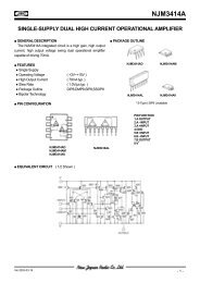
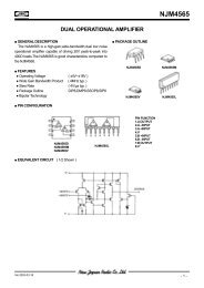
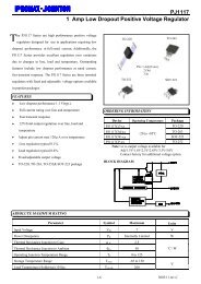
Interfaces<br />
QLogic Corporation<br />
The <strong>FAS366U</strong> interfaces consist of the microprocessor bus and the <strong>SCSI</strong> bus. Pins that support these interfaces<br />
and other chip operations are shown in figure 4.<br />
MICROPROCESSOR<br />
INTERFACE<br />
DMA AND<br />
MICROPROCESSOR<br />
INTERFACE<br />
RESET<br />
CLOCK<br />
POWER<br />
AND GROUND<br />
A3–0<br />
CS<br />
INT<br />
PAD7–0<br />
PADP<br />
PAUSE<br />
RD<br />
WR<br />
DACK<br />
DB15–0<br />
DBP1–0<br />
DBRD<br />
DBWR<br />
DREQ<br />
RESETI<br />
RESETO<br />
CLK<br />
VDD<br />
VSS<br />
42–45<br />
13<br />
<strong>FAS366U</strong><br />
3 61<br />
92–97, 99, 100<br />
91<br />
10<br />
14<br />
15 57<br />
9<br />
SEE NOTE<br />
127, 117<br />
4<br />
5<br />
8<br />
2<br />
1<br />
88<br />
SEE NOTE<br />
SEE NOTE<br />
Figure 4. <strong>FAS366U</strong> Functional Signal Grouping<br />
53366–580–01 B <strong>FAS366U</strong> 5<br />
58<br />
62<br />
33<br />
31<br />
56<br />
32<br />
SEE NOTE<br />
75, 63<br />
55<br />
11<br />
47<br />
39<br />
20<br />
38<br />
SEE NOTE<br />
86, 48<br />
36<br />
19<br />
41, 40<br />
SEE NOTE<br />
NOTE: DB15–0 = 126–122, 120–118, 116, 115, 113–108<br />
ESD15–0 = 101–104, 21–24, 49–52, 82–85<br />
NO CONNECT = 16, 37, 53, 60, 67, 90, 105<br />
SD15–0 = 76, 78–80, 26–28, 30, 64, 65, 68–70, 72–74<br />
VDD = 7, 12, 17, 35, 87, 106<br />
VSS = 6, 18, 25, 29, 34, 46, 54, 59, 66, 71, 77, 81, 89, 98, 107, 114, 121, 128<br />
ACK<br />
ATN<br />
BSY<br />
CD<br />
IO<br />
MSG<br />
REQ<br />
RST<br />
SD15–0<br />
SDP1–0<br />
SEL<br />
DIFFM<br />
DIFFSENS<br />
EBSY<br />
EIGS<br />
ERST<br />
ESD15–0<br />
ESDP1–0<br />
ESEL<br />
ETGS<br />
MODE1–0<br />
<strong>SCSI</strong><br />
INTERFACE<br />
DIFFERENTIAL<br />
MODE SUPPORT<br />
BUS CONFIGURATION<br />
NO CONNECT
QLogic Corporation<br />
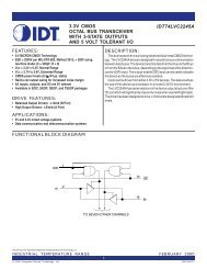
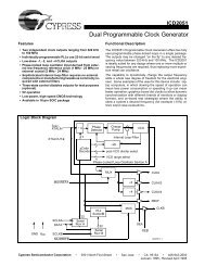
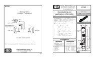
Packaging<br />
The <strong>FAS366U</strong> is available in a 128–pin plastic quad flat pack (PQFP). The pin diagram for this package is<br />
illustrated in figure 5. The <strong>FAS366U</strong> package dimensions are shown in figure 6.<br />
ESD13<br />
ESD12<br />
NC<br />
VDD<br />
VSS<br />
DB0<br />
DB1<br />
DB2<br />
DB3<br />
DB4<br />
DB5<br />
VSS<br />
DB6<br />
DB7<br />
DBP0<br />
DB8<br />
DB9<br />
DB10<br />
VSS<br />
DB11<br />
DB12<br />
DB13<br />
DB14<br />
DB15<br />
DBP1<br />
VSS<br />
ESD14<br />
ESD15<br />
PAD0<br />
PAD1<br />
102<br />
101<br />
100<br />
99<br />
98<br />
97<br />
96<br />
95<br />
94<br />
93<br />
92<br />
91<br />
103<br />
104<br />
105<br />
106<br />
107<br />
108<br />
109<br />
110<br />
111<br />
112<br />
113<br />
114<br />
115<br />
116<br />
117<br />
ÁÁ<br />
ÁÁ<br />
118<br />
119<br />
120<br />
ÁÁ<br />
ÁÁ<br />
121<br />
122<br />
123<br />
ÁÁ<br />
ÁÁ<br />
124<br />
125<br />
126<br />
127<br />
128<br />
ÁÁ<br />
ÁÁ<br />
1<br />
2<br />
3<br />
4<br />
5<br />
6<br />
7<br />
8<br />
9<br />
10<br />
11<br />
12<br />
13<br />
14<br />
15<br />
16<br />
17<br />
18<br />
19<br />
20<br />
21<br />
22<br />
23<br />
24<br />
25<br />
26<br />
27<br />
28<br />
29<br />
30<br />
31<br />
32<br />
33<br />
34<br />
35<br />
36<br />
37<br />
38<br />
ÁÁ<br />
ÁÁ<br />
RESETO<br />
RESETI<br />
INT<br />
DBRD<br />
PAD2<br />
VSS<br />
PAD3<br />
PAD4<br />
PAD5<br />
PAD6<br />
PAD7<br />
PADP<br />
NC<br />
VSS<br />
CLK<br />
VDD<br />
ESDP1<br />
ESD0<br />
ESD1<br />
ESD2<br />
ESD3<br />
VSS<br />
SD12<br />
SD13<br />
SD14<br />
VSS<br />
SD15<br />
SDP1<br />
90<br />
89<br />
88<br />
87<br />
86<br />
85<br />
84<br />
83<br />
82<br />
81<br />
80<br />
79<br />
78<br />
77<br />
76<br />
75<br />
74<br />
73<br />
72<br />
71<br />
70<br />
69<br />
68<br />
67<br />
66<br />
65<br />
<strong>FAS366U</strong><br />
DBWR<br />
VSS<br />
VDD<br />
DREQ<br />
DACK<br />
PAUSE<br />
DIFFM<br />
VDD<br />
CS<br />
RD<br />
WR<br />
NC<br />
VDD<br />
VSS<br />
ETGS<br />
EIGS<br />
ESD11<br />
ESD10<br />
ESD9<br />
ESD8<br />
VSS<br />
SD11<br />
NC = NO CONNECT<br />
Figure 5. <strong>FAS366U</strong> Pin Diagram<br />
SD0<br />
SD1<br />
SD2<br />
VSS<br />
SD3<br />
SD4<br />
SD5<br />
NC<br />
VSS<br />
SD6<br />
VSS<br />
SD8<br />
IO<br />
REQ<br />
CD<br />
VSS<br />
VDD<br />
ESEL<br />
NC<br />
ERST<br />
6 <strong>FAS366U</strong> 53366–580–01 B<br />
SD10<br />
SD9<br />
64<br />
63<br />
62<br />
61<br />
ÁÁ<br />
SD7<br />
SDP0<br />
ATN<br />
Á53 Á 52<br />
Á<br />
Á 51<br />
50<br />
Á<br />
Á 49<br />
Á48Á Á 47<br />
Á<br />
Á 46<br />
45<br />
Á<br />
Á<br />
60<br />
59<br />
58<br />
57<br />
56<br />
55<br />
54<br />
44<br />
Á43Á Á 42<br />
Á<br />
Á<br />
41<br />
40<br />
Á 39<br />
BSY<br />
NC<br />
VSS<br />
ACK<br />
RST<br />
MSG<br />
SEL<br />
VSS<br />
NC<br />
ESD4<br />
ESD5<br />
ESD6<br />
ESD7<br />
ESDP0<br />
DIFFSENS<br />
VSS<br />
A0<br />
A1<br />
A2<br />
A3<br />
MODE1<br />
MODE0<br />
EBSY
17.2 � 0.25<br />
PIN 102<br />
PIN 103<br />
14.00<br />
PIN 128<br />
PIN 1<br />
23.2 � 0.25<br />
20.00<br />
INDEX MARK<br />
Electrical Characteristics<br />
PIN 38<br />
PIN 65<br />
PIN 64<br />
PIN 39<br />
0.8 � 0.15<br />
Figure 6. <strong>FAS366U</strong> Mechanical Drawings<br />
QLogic Corporation<br />
53366–580–01 B <strong>FAS366U</strong> 7<br />
4� TYP<br />
Table 1. Operating Conditions<br />
A<br />
0.18 � 0.05<br />
1.6<br />
REF<br />
DETAIL A<br />
0.23 � 0.05<br />
0.5 � 0.1<br />
2.8 TYP<br />
3.4 MAX<br />
+ 0.1<br />
0.3<br />
–0.05<br />
NOTE: ALL DIMENSIONS ARE IN MILLIMETERS.<br />
Symbol Description Minimum Maximum Unit<br />
VDD Supply voltage 4.75 5.25 V<br />
IDD a Supply current (static IDD) TBD mA<br />
IDD b Supply current (dynamic IDD) TBD mA<br />
TA Ambient temperature 0 70 o C<br />
Table Notes<br />
Conditions not within the operating conditions but within the absolute maximum stress ratings may cause the chip to<br />
malfunction.<br />
a Static IDD is measured with no clocks running and all inputs forced to VDD, all outputs unloaded, and all<br />
bidirectional pins configured as inputs.<br />
b Dynamic IDD is dependent on the application.
QLogic Corporation<br />
Specifications are subject to change without notice.<br />
QLogic is a trademark of QLogic Corporation.<br />
�July 14, 1995 QLogic Corporation, 3545 Harbor Blvd., Costa Mesa, CA 92626, (800) ON–CHIP–1 or (714) 438–2200<br />
8 <strong>FAS366U</strong> 53366–580–01 B