
You also want an ePaper? Increase the reach of your titles
YUMPU automatically turns print PDFs into web optimized ePapers that Google loves.
<strong>DKG</strong>-<strong>215</strong><br />
MANUAL AND<br />
REMOTE START UNIT<br />
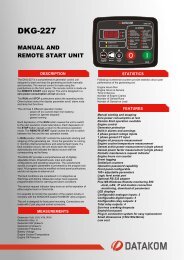
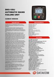
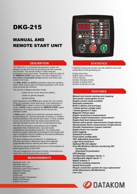
The <strong>DKG</strong>-<strong>215</strong> is a comprehensive generator control unit<br />
designed to start and stop the generating set both manually<br />
and remotely. The manual control is made using the<br />
pushbuttons on the front panel. The remote control is made via<br />
the REMOTE START input signal. The unit is designed in a<br />
zero power consumption at rest structure and draws zero<br />
current in off mode.<br />
The RUN, STOP and AUTO pushbuttons select the operating<br />
mode. Other buttons select the display parameter scroll, alarm<br />
mute and lamp test functions.<br />
The unit has 3 different operation modes:<br />
- power off (no current drain from battery)<br />
- power on (genset stopped)<br />
- genset running<br />
DESCRIPTION<br />
Each depression of the RUN button causes the unit to switch<br />
to the next operation mode listed above. Each depression of<br />
the STOP button causes a return to the previous operation<br />
mode. If AUTO mode is selectedi the REMOTE START signal<br />
causes the unit to switch between the first and the last<br />
operation modes.<br />
In RUN position, <strong>DKG</strong>-<strong>215</strong> controls the automatic starting of<br />
the generating set . Once the generator is running, it monitors<br />
internal protections and external fault inputs. If a fault condition<br />
occurs, the unit shuts down the engine automatically and<br />
indicates the failure source with the corresponding led lamp.<br />
The <strong>DKG</strong>-<strong>215</strong> provides a comprehensive set of digitally<br />
adjustable timers, threshold levels, input and output<br />
configurations and operating sequences. The unauthorized<br />
access to program parameters is prevented by the program lock<br />
input. All programs may be modified via front panel pushbuttons,<br />
and do not require an external unit.<br />
The fault conditions are considered in 2 categories as<br />
Warnings and Alarms. Measured values have separate<br />
programmable limits for warning and alarm conditions.<br />
The service request indicator lamp turns on at the expiration of<br />
either engine hours or time limits.<br />
The unit is designed for front panel mounting. Connections are<br />
made with 2 part plug and socket connectors.<br />
MEASUREMENTS<br />
Generator Volt: L1-N<br />
Generator Amp: L1<br />
Generator KW phase L1<br />
Generator power factor phase L1<br />
Generator Frequency<br />
Battery Voltage<br />
Engine rpm<br />
Engine Coolant Temperature<br />
Engine Oil Pressure<br />
Engine Fuel Level<br />
Following incremental counters provide statistics about past<br />
performance of the generating set:<br />
Engine Hours Run<br />
Engine Hours to Service<br />
Time to Service<br />
Number of Engine Cranks<br />
Number of Genset Runs<br />
Number of Genset on Load<br />
STATISTICS<br />
FEATURES<br />
Manual and remote starting and stopping<br />
Zero power consumption at rest<br />
Engine control mode available<br />
Generator protection<br />
Built in alarms and warnings<br />
1 phase genset voltage input<br />
1 phase genset CT input<br />
Magnetic Pickup input<br />
Engine oil pressure measurement<br />
Engine coolant temperature measurement<br />
Engine fuel level measurement<br />
Genset active power measurement (single phase)<br />
Genset power factor measurement (single phase)<br />
Periodic maintenance request indicator<br />
Engine hours run counter<br />
Event logging<br />
Statistical counters<br />
Front panel configurable<br />
100+ adjustable parameters<br />
Logic level serial port<br />
Optional RS-232 adapter<br />
Free MS-Windows Remote monitoring SW:<br />
-monitoring<br />
-download of parameters<br />
LED displays<br />
Configurable analogue inputs: 3<br />
Configurable digital inputs: 5<br />
Digital outputs: 5<br />
Survives cranking dropouts<br />
Sealed front panel<br />
Plug-in connection system for easy replacement<br />
Small dimensions (96x96x53mm)<br />
Low cost
TELEMETRY AND REMOTE PROGRAMMING<br />
The <strong>DKG</strong>-<strong>215</strong> module provides the user with large telemetry<br />
facilities via its optional logic level serial port.<br />
The PC program is used for below purposes:<br />
-parameter upload/download<br />
-remote monitoring<br />
-diagnostics and analysis<br />
EVENT LOGGING<br />
The <strong>DKG</strong>-<strong>215</strong> records last 12 events. Recorded events are:<br />
-alarms and warnings<br />
-generator run / stop information<br />
Event records are only displayed on the PC screen.<br />
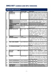
RELAY OUTPUTS<br />
The unit provides 5 digital outputs and 3 of them have<br />
programmable functions, selectable from a list.<br />
In addition to genset control signals, any specific alarm<br />
information may be output as a relay contact.<br />
DIGITAL INPUTS<br />
The unit has 5 configurable digital inputs. Each input has<br />
following programmable parameters:<br />
-alarm type: shutdown / warning / no alarm<br />
-alarm polling: on engine running / always<br />
-latching / non-latching operation,<br />
-contact type: NO / NC<br />
-switching: BAT+ / BAT-<br />
The REMOTE START input is not programmable and if used,<br />
should be supplied with the battery positive voltage.<br />
ANALOG INPUTS<br />
Engine analog inputs are provided for following functions:<br />
-Coolant temperature<br />
-Oil pressure<br />
-Fuel level<br />
The analog inputs connect to resistive sender units to provide<br />
precise and adjustable protection. The inputs have<br />
programmable sensor characteristics so that they are suitable<br />
for any type and any brand of sensors.<br />
TECHNICAL SPECIFICATIONS<br />
Alternator voltage: 15-300 V-AC (Ph-N)<br />
Alternator frequency: 0-100 Hz.<br />
Current input: from current transformer, .../5A. Max load 0.7VA<br />
Digital inputs: 0 - 30 V-DC<br />
Analog inputs: 0 to 5000 ohms<br />
Magnetic pickup input: 1 to 30V-AC, 0 to 10 KHz.<br />
DC Supply Range: 9.0 to 33.0 V-DC<br />
Cranking dropouts: survives 0 V for 100ms.<br />
Typical Standby Current: 0 mA-DC<br />
Maximum Operating Current: 100 mA-DC (digital outputs open)<br />
Digital Outputs: Negative pulling protected semiconductor<br />
outputs, 1 A / 28V<br />
Charge excitation current: 150mA minimum.<br />
Serial port: logic levels, 2400 bauds, no parity, 1 bit stop<br />
Operating temp.: -20�C (-4�F) to 70 �C (158�F).<br />
Storage temp.: -30�C (-22�F) to 80 �C (176�F).<br />
Maximum humidity: 95% non-condensing.<br />
IP Protection: IP65 from front panel, IP30 from the rear.<br />
Dimensions: 96 x 96 x 53 mm (WxHxD)<br />
Panel Cut-out Dimensions: 91x91 mm minimum.<br />
Mounting: Front panel mounted with rear retaining plastic<br />
brackets.<br />
Weight: 170 g (approx.)<br />
Case Material: High Temperature ABS (UL94-V0)<br />
Conformity (EU directives)<br />
-2006/95/EC (low voltage)<br />
-2004/108/EC (electro-magnetic compatibility)<br />
Norms of reference:<br />
EN 61010 (safety requirements)<br />
EN 61326 (EMC requirements)