DKG-317 MANUAL & REMOTE START UNIT - Datakom
DKG-317 MANUAL & REMOTE START UNIT - Datakom
DKG-317 MANUAL & REMOTE START UNIT - Datakom

Create successful ePaper yourself
Turn your PDF publications into a flip-book with our unique Google optimized e-Paper software.
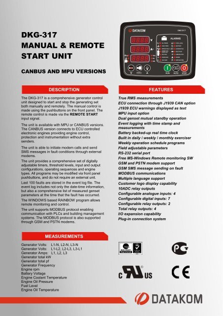
<strong>DKG</strong>-<strong>317</strong><br />
<strong>MANUAL</strong> & <strong>REMOTE</strong><br />
<strong>START</strong> <strong>UNIT</strong><br />
CANBUS AND MPU VERSIONS<br />
DESCRIPTION<br />
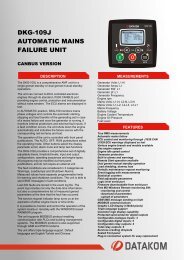
The <strong>DKG</strong>-<strong>317</strong> is a comprehensive generator control<br />
unit designed to start and stop the generating set<br />
both manually and remotely. The manual control is<br />
made using the pushbuttons on the front panel. The<br />
remote control is made via the <strong>REMOTE</strong> <strong>START</strong><br />
input signal.<br />
The unit is available with MPU or CANBUS versions.<br />
The CANBUS version connects to ECU controlled<br />
electronic engines providing engine control,<br />
protection and instrumentation without extra<br />
senders.<br />
The unit is able to initiate modem calls and send<br />
SMS messages in fault conditions through external<br />
modems.<br />
The unit provides a comprehensive set of digitally<br />
adjustable timers, threshold levels, input and output<br />
configurations, operating sequences and engine<br />
types. All programs may be modified via front panel<br />
pushbuttons, and do not require an external unit.<br />
Last 100 faults are stored in the event log file. The<br />
event log includes not only the date-time information,<br />
but also a comprehensive list of measured genset<br />
parameters at the time that the fault has occurred.<br />
The WINDOWS based RAINBOW program allows<br />
remote monitoring and control.<br />
The unit supports MODBUS protocol enabling<br />
communication with PLCs and building management<br />
systems. The MODBUS protocol is also supported<br />
through GSM and PSTN modems.<br />
MEASUREMENTS<br />
Generator Volts: L1-N, L2-N, L3-N<br />
Generator Volts: L1-L2, L2-L3, L3-L1<br />
Generator Amps: L1, L2, L3<br />
Generator total kW<br />
Generator total pf<br />
Generator Frequency<br />
Engine rpm<br />
Battery Voltage<br />
Engine Coolant Temperature<br />
Engine Oil Pressure<br />
Fuel Level<br />
Engine Oil Temperature<br />
FEATURES<br />
True RMS measurements<br />
ECU connection through J1939 CAN option<br />
J1939 ECU warnings displayed as text<br />
MPU input option<br />
Dual genset mutual standby operation<br />
Event logging with time stamp and<br />
measurements<br />
Battery backed-up real time clock<br />
Built in daily / weekly / monthly exerciser<br />
Weekly operation schedule programs<br />
Field adjustable parameters<br />
RS-232 serial port<br />
Free MS-Windows Remote monitoring SW<br />
GSM and PSTN modem support<br />
GSM SMS message sending on fault<br />
MODBUS communications<br />
Multiple language support<br />
Customer logo display capability<br />
10ADC relay outputs<br />
Configurable analogue inputs: 4<br />
Configurable digital inputs: 7<br />
Configurable relay outputs: 2<br />
Total relay outputs: 4<br />
I/O expansion capability<br />
Plug-in connection system
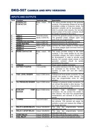
DIGITAL INPUTS<br />
The unit has 7 configurable digital inputs. Each input is fully<br />
configurable with selectable names, alarm type, polling,<br />
latching and contact type.<br />
ANALOG INPUTS<br />
Engine analog inputs are provided for coolant temperature, oil<br />
pressure, oil temperature and fuel level. The inputs have<br />
programmable sensor characteristics so that they are suitable<br />
for any type and brand of sensors.<br />
RELAY OUTPUTS<br />
The unit provides 4 relay outputs and 2 of them have<br />
programmable functions, selectable from a list. Any function or<br />
alarm condition may be output as a relay output.<br />
Using two Relay Expansion Modules, the number of relays<br />
may be increased to 20, 16 of them being volt-free contacts.<br />
EVENT LOGGING<br />
The unit records last 100 events with date-time stamp and a<br />
total of 18 measured parameters.<br />
TELEMETRY AND <strong>REMOTE</strong> PROGRAMMING<br />
The unit provides the user with large telemetry facilities via its<br />
standard RS-232 serial port, connecting either to a PC, PLC or<br />
a GSM or PSTN modem. It supports both RAINBOW and<br />
MODBUS communication protocols. The standard PC software<br />
offers local and modem operation capabilities as well as<br />
modem networking feature.<br />
The PC program is used for below purposes:<br />
-parameter upload/download<br />
-remote monitoring and control<br />
-diagnostics and analysis<br />
The MODBUS interface allows the unit to be integrated in<br />
building management systems.<br />
TECHNICAL SPECIFICATIONS<br />
Alternator voltage: 0 to 300 V-AC (Ph-N)<br />
Alternator frequency: 0-100 Hz.<br />
DC Supply Range: 9.0 to 33.0 V-DC<br />
Cranking dropouts: survives 0 V for 100ms.<br />
Typical Standby Current: 100 mA-DC<br />
Maximum Operating Current: 250 mA-DC (Relay outputs open)<br />
DC Outputs: 10A @ 28V<br />
Charge excitation: min 2 Watts<br />
Magnetic pickup input:: 0.5 – 30 V-AC.<br />
Magnetic pickup frequency: 10 KHz max.<br />
Current inputs: from CTs, .../5A. Max load 0.7VA per phase.<br />
Analog input range: 0-5000 ohms.<br />
Serial port: RS-232, 9600 bauds, no parity, 1 bit stop<br />
Operating temp.: -40°C (-40°F) to 70°C (158°F).<br />
Storage temp.: -55°C (-67°F) to 80°C (176°F).<br />
Maximum humidity: 95% non-condensing.<br />
Dimensions: 172x 134 x 46 mm (WxHxD)<br />
Panel Cut-out Dimensions: 151x111 mm minimum.<br />
Weight: 300 g (approx.)<br />
Case Material: High Temperature ABS/PC (UL94-V0)<br />
IP Protection: IP65 from front panel, IP30 from the rear<br />
CE Conformity reference standards:<br />
EN 61010 (safety requirements)<br />
EN 61326 (EMC requirements)<br />
UL / CSA Conformity: certificate # 20110527-E314374<br />
UL 508, Edition 17<br />
UL 2200, 1st Edition.<br />
UL 840 Edition 3<br />
CSA C22.2 NO. 14 - Edition 10