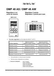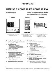
Operating Instructions DMP 48 AS / DMP 48 AW - Dold GmbH
Operating Instructions DMP 48 AS / DMP 48 AW - Dold GmbH
Operating Instructions DMP 48 AS / DMP 48 AW - Dold GmbH

Create successful ePaper yourself
Turn your PDF publications into a flip-book with our unique Google optimized e-Paper software.
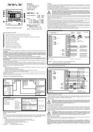
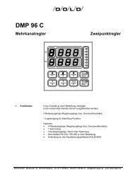
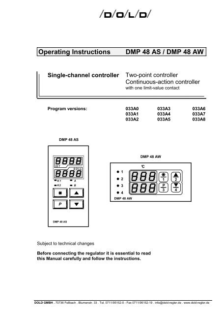
<strong>Operating</strong> <strong>Instructions</strong> <strong>DMP</strong> <strong>48</strong> <strong>AS</strong> / <strong>DMP</strong> <strong>48</strong> <strong>AW</strong><br />
Single-channel controller Two-point controller<br />
Continuous-action controller<br />
with one limit-value contact<br />
Program versions: 033A0 033A3 033A6<br />
033A1 033A4 033A7<br />
033A2 033A5 033A8<br />
IS T<br />
<strong>DMP</strong> <strong>48</strong> <strong>AS</strong><br />
K 1<br />
K2 B<br />
P<br />
<strong>DMP</strong> <strong>48</strong> <strong>AS</strong><br />
S O LL<br />
Subject to technical changes<br />
A<br />
<strong>DMP</strong> <strong>48</strong> <strong>AW</strong><br />
<strong>DMP</strong> <strong>48</strong> <strong>AW</strong><br />
Before connecting the regulator it is essential to read<br />
this Manual carefully and follow the instructions.<br />
1<br />
2<br />
3<br />
4<br />
1 2<br />
P<br />
3 4<br />
DOLD GMBH . 70736 Fellbach . Blumenstr. 33 . Tel. 0711/95152-0 - Fax 0711/95152-19 . info@dold-regler.de . www.dold-regler.de<br />
°C
DOLD GMBH <strong>Operating</strong> instructions <strong>DMP</strong> <strong>48</strong> <strong>AS</strong> / <strong>AW</strong><br />
Contents<br />
1. INSTALLING THE CONTROLLER:........................................................................4<br />
1.1 Terminal connection diagram:.......................................................................................................4<br />
1.2 Identification plate:.........................................................................................................................4<br />
1.3 Please note during installation:......................................................................................................5<br />
1.4 Mechanical Data:...........................................................................................................................5<br />
2. TECHNICAL DATA, INPUTS:.................................................................................6<br />
2.1 Analog inputs:................................................................................................................................6<br />
2.1.1 Technical Data, inputs:...............................................................................................................6<br />
2.1.2 Error-handling at input:...............................................................................................................7<br />
2.2 Digital inputs:.................................................................................................................................7<br />
3. CONTROL RESPONSE: ........................................................................................7<br />
3.1 Controller function: ........................................................................................................................7<br />
3.1.1 Two-point controller:...................................................................................................................7<br />
3.1.2 Continuous-action controller:......................................................................................................8<br />
3.1.3 Three-point response: ................................................................................................................8<br />
3.2 Actuator function: ..........................................................................................................................8<br />
4. OUTPUTS:..............................................................................................................9<br />
4.1 Potential-free relay contacts, make contact: .................................................................................9<br />
4.2 Logic output (optional):..................................................................................................................9<br />
4.3 Analog output: ...............................................................................................................................9<br />
4.3.1 Technical data, analog output: ...................................................................................................9<br />
4.4 Output responses in cases of error: ..............................................................................................9<br />
5. AUXILIARY POWER: ...........................................................................................10<br />
6. DISPLAY:..............................................................................................................10<br />
6.1 Upper 7-segment display ............................................................................................................10<br />
6.2 Lower 7-segment display.............................................................................................................11<br />
6.3 LED's 3mm:.................................................................................................................................11<br />
7. EXPLANATIONS OF SYMBOLS:.........................................................................11<br />
<strong>DMP</strong> <strong>48</strong> <strong>AS</strong> Version: 033 Number of pages: 2 of 25<br />
<strong>DMP</strong> <strong>48</strong> <strong>AW</strong> Edition: 08.08.2006 A0e033.doc
DOLD GMBH <strong>Operating</strong> instructions <strong>DMP</strong> <strong>48</strong> <strong>AS</strong> / <strong>AW</strong><br />
8. OPERATION:........................................................................................................12<br />
8.1 Setting parameters on the various levels: ...................................................................................12<br />
8.2 The various levels: ......................................................................................................................13<br />
8.3 Setting the setpoint:.....................................................................................................................13<br />
8.3.1 Setting the setpoint via the operator level: ...............................................................................13<br />
8.3.2 Setting the setpoint level via the setpoint entry level:...............................................................14<br />
8.4 The configuration level: ...............................................................................................................14<br />
8.4.1 Switching response of the K 2 limit-value contact: ...................................................................17<br />
8.5 The parameterization level: .........................................................................................................18<br />
8.6 The self-optimization level:..........................................................................................................19<br />
8.6.1 Monitoring the optimization process:........................................................................................21<br />
8.7 The information level: ..................................................................................................................22<br />
9. LINE COMPENSATION, ZERO-POINT OFFSET:................................................23<br />
9.1 Line compensation: .....................................................................................................................23<br />
9.2 Zero-point offset: .........................................................................................................................23<br />
10. ERROR MESSAGES:.........................................................................................24<br />
10.1 Error messages (display): .........................................................................................................24<br />
11. PROGRAM VERSION: .......................................................................................24<br />
12. IMMUNITY: .........................................................................................................24<br />
<strong>DMP</strong> <strong>48</strong> <strong>AS</strong> Version: 033 Number of pages: 3 of 25<br />
<strong>DMP</strong> <strong>48</strong> <strong>AW</strong> Edition: 08.08.2006 A0e033.doc
DOLD GMBH <strong>Operating</strong> instructions <strong>DMP</strong> <strong>48</strong> <strong>AS</strong> / <strong>AW</strong><br />
1. Installing the controller:<br />
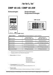
1.1 Terminal connection diagram:<br />
This connection diagram shows maximum terminal assignment for the controller when all connection<br />
possibilities are used. The appropriate terminal assignment (depending of the type of<br />
controller used) can be found in the accompanying connection diagram.<br />
Connection diagram number according to identification plate: <strong>AS</strong>P 675XXX<br />
+<br />
-<br />
+<br />
-<br />
1<br />
2<br />
3<br />
4<br />
5<br />
6<br />
7<br />
8<br />
9<br />
10<br />
11<br />
12<br />
13<br />
14<br />
15<br />
Resistance Resistance<br />
thermometer, thermometer,<br />
3-wire leads 2-wire leads<br />
K 1<br />
K 2<br />
Logic input<br />
+<br />
U/I output<br />
-<br />
Figure 1: <strong>DMP</strong> <strong>48</strong> <strong>AS</strong> / <strong>AW</strong> connection diagram<br />
1.2 Identification plate:<br />
The following information is<br />
important and should be given<br />
whenever you have any technical<br />
questions:<br />
Type of controller<br />
Factory number<br />
Model number<br />
Program version<br />
<strong>DMP</strong> <strong>48</strong> <strong>AS</strong><br />
<strong>Operating</strong> voltage:<br />
<strong>Operating</strong> voltage<br />
Relay outputs<br />
Logic outputs (optional)<br />
Switching capacity: 500 VA at 230 VAC<br />
Factory number:<br />
Input:<br />
Logic input:<br />
Outputs:<br />
<strong>AS</strong>P 675XXX<br />
XXX V +/-10%<br />
XXXXXX<br />
XXXXX<br />
configurable function<br />
relay<br />
Logic outputs<br />
Model No: 850XXX Program vers.XXXXX<br />
Figure 2: <strong>DMP</strong> <strong>48</strong> <strong>AS</strong> / <strong>AW</strong> identification plate<br />
Thermal converter<br />
Caution:<br />
Terminal 2 (-) and terminal 6 (-)<br />
do not have the same potential!<br />
<strong>DMP</strong> <strong>48</strong> <strong>AS</strong> Version: 033 Number of pages: 4 of 25<br />
<strong>DMP</strong> <strong>48</strong> <strong>AW</strong> Edition: 08.08.2006 A0e033.doc<br />
and<br />
+<br />
-<br />
Type of controller<br />
Terminal connection diagram number<br />
as per order<br />
as per order<br />
as per order<br />
Program version
DOLD GMBH <strong>Operating</strong> instructions <strong>DMP</strong> <strong>48</strong> <strong>AS</strong> / <strong>AW</strong><br />
1.3 Please note during installation:<br />
External safety monitoring should be provided.<br />
Before connecting or starting up the <strong>DMP</strong> <strong>48</strong> <strong>AS</strong> / <strong>AW</strong> controller it is absolutely necessary to<br />
make sure that supply voltage corresponds to the nominal voltage given on the identification<br />
plate.<br />
Electrical connections must be made according to the accompanying connection diagram and<br />
the regulations of the local energy supply company must be observed.<br />
The unit must be protected from dampness (especially condensation) and heavy soiling in order<br />
to prevent malfunctioning.<br />
The <strong>DMP</strong> <strong>48</strong> <strong>AS</strong> / <strong>AW</strong> controller must be equipped with an RC network filter to reduce the effects<br />
of interference from the power supply network.<br />
An additional external filter must be switched into the controller’s power feed or other appropriate<br />
measures taken to prevent malfunction in the event of power supply faults.<br />
Sensor lines must be shielded. Unshielded sensor lines can lead to malfunctions.<br />
Controller and inductive loads, as well as sensor lines and load lines must be arranged in such a<br />
way that they cannot cause any interference to each other.<br />
Down-stream contractor relays must be equipped with RC suppressor circuits as per manufacturer’s<br />
instructions. Failure to use suppressor circuits could lead to the occurrence of short, high<br />
voltage peaks, which in turn can cause malfunctioning and excessive wear on contactors.<br />
The equalizing line must extend all the way to the controller supply terminals.<br />
Ambient temperature must lie within the range between 0...+50°C.<br />
All pre-set parameters must be checked during initial start-up and adapted to local conditions<br />
(systems)!<br />
1.4 Mechanical Data:<br />
Protection class: VDE 0631<br />
Insulation group: C as per DIN VDE 0110 b<br />
Type of protection: As per DIN VDE 0470 (replaces DIN 40 050)<br />
EN 60 529 / IEC 529<br />
Front panel: IP 50 (optionally: IP 54 with the proper mounting<br />
and a suitable sealing ring)<br />
Housing: IP 30<br />
IP 20<br />
Housing: Pull-out housing for mounting control panel with a B fastener as<br />
per DIN 43 835 (M 4 screw clamp)<br />
Material: PPO, glass-fiber reinforced (Noryl GFN2SE1)<br />
self-extinguishing, non-dripping<br />
fire protection class UL 94 V1<br />
Front panel dimensions: 96 x <strong>48</strong> mm DIN 43 700<br />
Control panel cutout: 92 +0.8 x 45 +0.6 mm<br />
Recess depth: approx. 125 mm including screwed plug connector<br />
Terminal connections: Screwed socket strips<br />
nominal cross section 2.5 mm 2<br />
Weight: approx. 420 g<br />
<strong>DMP</strong> <strong>48</strong> <strong>AS</strong> Version: 033 Number of pages: 5 of 25<br />
<strong>DMP</strong> <strong>48</strong> <strong>AW</strong> Edition: 08.08.2006 A0e033.doc
DOLD GMBH <strong>Operating</strong> instructions <strong>DMP</strong> <strong>48</strong> <strong>AS</strong> / <strong>AW</strong><br />
Ambient conditions: <strong>Operating</strong> temperature range: 0...+50°C<br />
Storage temperature range: -30...+70°C<br />
Climatic utilization category: as per DIN 40 040,<br />
corresponding to 75% relative humidity<br />
without moisture condensation<br />
2. Technical data, inputs:<br />
2.1 Analog inputs:<br />
Input as per identification plate or sensor ID:<br />
• Pt 100 three-wire lead<br />
• Fe-CuNi thermal converter, Type L<br />
• Ni Cr-Ni thermal converter, Type K.<br />
Sensor ID:<br />
Sensor: Sensor<br />
ID:<br />
ID according to<br />
ordering key:<br />
Max. display<br />
range:<br />
Max. setpoint<br />
range:<br />
<strong>DMP</strong> <strong>48</strong> <strong>AS</strong> Version: 033 Number of pages: 6 of 25<br />
<strong>DMP</strong> <strong>48</strong> <strong>AW</strong> Edition: 08.08.2006 A0e033.doc<br />
Program<br />
version:<br />
Pt 100 P 1 P 1 -69...149°C -50...100°C 033A0<br />
Pt 100 P 2 P 2 -69...249°C -50...200°C 033A1<br />
Pt 100 P 3 P 3 -69...349°C -50...300°C 033A2<br />
Pt 100 P 4 P 4 -69...699°C -50...600°C 033A3<br />
Pt 100 P 5 P 5 -169...149°C -150...100°C 033A4<br />
Fe-CuNi Type L tL1 L 1 -24...499°C 0...450°C 033A5<br />
Fe-CuNi Type L tL2 L 2 -24...899°C 0...850°C 033A6<br />
Ni Cr-Ni Type K tn1 K 1 -24...649°C 0...600°C 033A7<br />
Ni Cr-Ni Type K tn2 K 2 -24...1299°C 0...1200°C 033A8<br />
(See Information Level, Section 8.7, for instructions on querying sensor ID).<br />
2.1.1 Technical Data, inputs:<br />
Pt 100: Sensor current: constant 1 mADC<br />
Calibration precision: ≤ 0,15 % F.S.<br />
Linearity error: ≤ 0,1% F.S.<br />
Temperature drift characteristics: ≤ 100 ppm/K<br />
Equipped with sensor breakage cutoff and short circuit fuse<br />
Pt 100 three-wire lead: Automatic line resistance compensation via software<br />
(maximum permissible line resistance: 50 Ω per lead)<br />
Pt 100 two-wire lead: Line resistance correction (line compensation) of max. 9 Ω<br />
possible via software (external bridge clamps 2-3),<br />
Thermal converter: Calibration precision: ≤ 0.15% F.S.<br />
Linearity error: ≤ 0.15% F.S.<br />
Temperature drift characteristics<br />
(without reference point compensation): ≤ 80 ppm/K<br />
Effect of line resistance: ≤ 2μV/Ω
DOLD GMBH <strong>Operating</strong> instructions <strong>DMP</strong> <strong>48</strong> <strong>AS</strong> / <strong>AW</strong><br />
Reference point compensation<br />
Error recognition using a controller reference point > 70°C<br />
Sensor breakage cutoff<br />
General: Measurement cycle: 1 sec<br />
Resolution: ≥ 12 bit<br />
RC and diode protection circuit for each input<br />
Measuring-circuit<br />
monitoring: Error shown on display<br />
Protective circuits: Hardware watchdog and power-fail<br />
Data backup: EPROM, semiconductor storage,<br />
Hardware-protected calibrated values<br />
2.1.2 Error-handling at input:<br />
If the input signal leaves the maximum display range (for sensor ID) this is recognized as an error,<br />
evaluated, and shown on the display (error message "Er 1")<br />
2.2 Digital inputs:<br />
Logic input via potential-free contact, with configurable function<br />
Function:<br />
Contact:<br />
Contact open Contact closed<br />
Setpoint switchover Enter value for setpoint 1 Enter value for setpoint 2<br />
Stop function - Control contact K 1 deactivated<br />
Programming block Programming function block Programming function release<br />
3. Control response:<br />
3.1 Controller function:<br />
Control response is configurable:<br />
• Two-point response for heating or cooling, with adjustable hysteresis<br />
• Two-point response for heating or cooling with PDPID – control characteristic and selfoptimization<br />
algorithm<br />
• Continuous-action control response for heating and cooling with PDPID – control characteristic<br />
and self-optimization algorithm<br />
• Three-point response with adjustable hysteresis<br />
• Three-point response with one-sided PDPID – control characteristic and self-optimization algorithm<br />
3.1.1 Two-point controller:<br />
Relay output K 1: Switching function configurable: Control contact or limit comparator<br />
<strong>DMP</strong> <strong>48</strong> <strong>AS</strong> Version: 033 Number of pages: 7 of 25<br />
<strong>DMP</strong> <strong>48</strong> <strong>AW</strong> Edition: 08.08.2006 A0e033.doc
DOLD GMBH <strong>Operating</strong> instructions <strong>DMP</strong> <strong>48</strong> <strong>AS</strong> / <strong>AW</strong><br />
Relay output K 2: Switching function configurable: Limit-value contact (with adjustable<br />
hysteresis) and limit comparator<br />
Options: Logic output in place of relay output K 1 or K 2,<br />
actual-value output.<br />
3.1.2 Continuous-action controller:<br />
Output 1: Characteristic curve configurable (heating or cooling):<br />
Control output (relay output K 1 eliminated)<br />
Relay output K 2: Switching function configurable: Limit-value contact (with adjustable<br />
hysteresis) or limit comparator<br />
Option: Logic output in place of relay output K 2<br />
3.1.3 Three-point response:<br />
Three-point response is configurable:<br />
Relay output K 1 heating, relay output K 2 cooling,<br />
Relay output K 1 cooling, relay output K 2 heating,<br />
Options: Logic output in place of relay output K 1 or K 2 ,<br />
actual-value output.<br />
3.2 Actuator function:<br />
Reconfiguration of the "Aut" parameter makes it possible to use the unit as an actuator (actuator<br />
mode: parameter "Aut" set to OFF on the configuration level)<br />
The<br />
key can be used to switch smoothly back and forth between the controller<br />
functions (automatic function) and the actuator (manual function).<br />
The manipulated variable (%) set on the operator or setpoint entry level is relative to the cycle<br />
time (with relay output) or to output deviation (with continuous-action output).<br />
The currently activated function is stored in the EE-PROM. When the unit is powered up it is in<br />
the state of the function last stored.<br />
Display:<br />
Function:<br />
Display:<br />
Upper 7-segment display Lower 7-segment display<br />
Controller current actual value setpoint<br />
Actuator current actual value alternation between<br />
" -y- " / manipulated variable<br />
<strong>DMP</strong> <strong>48</strong> <strong>AS</strong> Version: 033 Number of pages: 8 of 25<br />
<strong>DMP</strong> <strong>48</strong> <strong>AW</strong> Edition: 08.08.2006 A0e033.doc
DOLD GMBH <strong>Operating</strong> instructions <strong>DMP</strong> <strong>48</strong> <strong>AS</strong> / <strong>AW</strong><br />
4. Outputs:<br />
Outputs as per identification plate and accompanying terminal connection diagram:<br />
4.1 Potential-free relay contacts, make contact:<br />
Contact load: ≤ 250V AC, ≤ 8 A resistive load<br />
at 500 VA typically 10 6 switching cycles<br />
4.2 Logic output (optional):<br />
Logic outputs for activating solid-state relays,<br />
(in place of relay outputs K 1 or K 2):<br />
Open collector, not galvanically separated, short-circuit-proof,<br />
typically: 0/10 VDC, maximum: 20 mA.<br />
4.3 Analog output:<br />
Analog output as per order and identification plate<br />
Two-point controller: actual-value output (optional): range limits configurable<br />
Continuous-<br />
action controller: Control output: characteristic curve (heating or cooling) configurable<br />
Current output: output value configurable: 0...20 mA<br />
4...20 mA<br />
Voltage output: output value as per order: 0...1 VDC<br />
0...2 VDC<br />
0...5 VDC<br />
4.3.1 Technical data, analog output:<br />
Current and voltage output: resolution: 8 Bit<br />
Current output: load: ≤ 250 Ω<br />
Voltage output (short-circuit-proof): internal resistance Ri: ≤ 250 Ω<br />
Note: Any current output present but not needed must have a terminating resistor of ≤ 250 Ω<br />
or a bridge (terminals 5-6).<br />
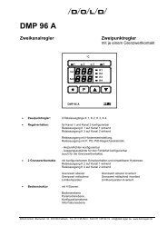
4.4 Output responses in cases of error:<br />
Output response in cases of sensor error:<br />
• Relay or logic outputs: Outputs assume the state defined on the configuration<br />
level.<br />
• Analog output: (continuous-action controller, actual-value output):<br />
output U: 0...1VDC, 0...2VDC, 0...5VDC: output signal: 0 VDC<br />
<strong>DMP</strong> <strong>48</strong> <strong>AS</strong> Version: 033 Number of pages: 9 of 25<br />
<strong>DMP</strong> <strong>48</strong> <strong>AW</strong> Edition: 08.08.2006 A0e033.doc
DOLD GMBH <strong>Operating</strong> instructions <strong>DMP</strong> <strong>48</strong> <strong>AS</strong> / <strong>AW</strong><br />
output I: 0...20 mA output signal: 0 mA<br />
output I: 4...20 mA output signal: 0 mA<br />
Incorrect actual-value response due to sensor error or response exceeding the set range:<br />
a) 0 VDC a) 0 VDC<br />
b) 0 VDC<br />
c) 0 VDC<br />
d) 0 mA<br />
e) 0 mA<br />
b) 0 VDC<br />
c) 0 VDC<br />
d) 0 mA<br />
e) 4 mA<br />
Max. display range<br />
Beginning of range "AnL" End of range "AnH"<br />
a) 0...1 VDC<br />
b) 0...2 VDC<br />
c) 0...5 VDC<br />
d) 0...20 mA<br />
e) 4...20 mA<br />
Set analog range<br />
Error message "Er.1" Error message "Er.1"<br />
(X < display range)<br />
(X > display range)<br />
Figure 3: Actual-value response in cases of error<br />
5. Auxiliary power:<br />
Auxiliary power (operating voltage) as per identification plate:<br />
a) 1 VDC a) 0 VDC<br />
b) 2 VDC<br />
c) 5 VDC<br />
d) 20 mA<br />
e) 20 mA<br />
b) 0 VDC<br />
c) 0 VDC<br />
d) 0 mA<br />
e) 0 mA<br />
Actual value X<br />
Standard: 230 VAC (±10%), <strong>48</strong>...62 Hz,<br />
Power consumption, depending on model: ≤ 4 VA,<br />
Not affected by voltage fluctuations within the defined range<br />
6. Display:<br />
• Actual-value and setpoint display: resolution adjustable<br />
• Setpoint display: display range adjustable.<br />
General information:<br />
Powering up:<br />
When power is turned on the following displays appear:<br />
• On the upper 7-segment display: the parameter "P.nr".<br />
• On the lower 7-segment display: the current program number "X.X".<br />
After approx. 5 sec. the controller switches to normal operating mode.<br />
Outputs are inactive during a cold start.<br />
6.1 Upper 7-segment display<br />
shows:<br />
• the actual value<br />
<strong>DMP</strong> <strong>48</strong> <strong>AS</strong> Version: 033 Number of pages: 10 of 25<br />
<strong>DMP</strong> <strong>48</strong> <strong>AW</strong> Edition: 08.08.2006 A0e033.doc
DOLD GMBH <strong>Operating</strong> instructions <strong>DMP</strong> <strong>48</strong> <strong>AS</strong> / <strong>AW</strong><br />
• parameter designation in entry mode<br />
6.2 Lower 7-segment display<br />
shows:<br />
• setpoint<br />
• parameter value in entry mode<br />
• alternation between " -y- " / manipulated variable when actuator function is activated (manual<br />
function)<br />
• alternation between setpoint (auxiliary setpoint) / "Opt" during the self-optimization procedure.<br />
6.3 LED's 3mm:<br />
LED: K 1 (1) yellow lights up when output K 1 is active<br />
LED: K 2 (2) yellow lights up when output K 2 is active<br />
LED: A (3) yellow lights up when continuous-action controller is functioning<br />
LED: B (4) yellow lights up when value for "setpoint 2" is entered<br />
7. Explanations of symbols:<br />
Display: Meaning:<br />
"P.nr" Current program number<br />
"SP.1" Setpoint 1<br />
"SP.2" Setpoint 2<br />
" -y- " Manipulated actuator value<br />
"Cod" Code entry<br />
"Con" Enter configuration level<br />
"Cor" Line compensation or zero-point offset<br />
"rA.H" Set upper limit of setpoint range<br />
"rA.L" Set lower limit of setpoint range<br />
"Co.1" Configuration, relay contact K 1<br />
"Co.2" Configuration, relay contact K 2<br />
"Fd.1" fault on control output K 1<br />
"Fd.2" fault on control output K 2<br />
"rES" Display resolution<br />
"Aut" Configuration of automatic function<br />
"Co.u" Configuration of setpoint setting<br />
"Co.A" Configuration of analog input<br />
"An.H" Setting of upper measuring range limit for actual-value output<br />
"An.L" Setting of lower measuring range limit for actual-value output<br />
"Co.L" Configuration of logic input<br />
"3-P" Configuration of three-point response<br />
"uSr" Enter setpoint entry level<br />
"PAr" Enter parameterization level<br />
"Pb.1" Proportional band, control contact K 1<br />
"ti.1" Reset time, control contact K 1<br />
"td.1" Derivative action time, control contact K 1<br />
"CY.1" Cycle time, control contact K 1<br />
"HY.1" Switching hysteresis, control contact K 1<br />
<strong>DMP</strong> <strong>48</strong> <strong>AS</strong> Version: 033 Number of pages: 11 of 25<br />
<strong>DMP</strong> <strong>48</strong> <strong>AW</strong> Edition: 08.08.2006 A0e033.doc
DOLD GMBH <strong>Operating</strong> instructions <strong>DMP</strong> <strong>48</strong> <strong>AS</strong> / <strong>AW</strong><br />
8. Operation:<br />
"bd.1" Symmetrical. spreading, limit comparator K 1<br />
"LA.2" Absolute setpoint value, limit-value contact K 2<br />
"Lr.2" Relative setpoint value, limit-value contact K 2<br />
"bd.2" Symmetrical. spreading, limit comparator K 2<br />
"HY.2" Switching hysteresis, limit-value contact K 2<br />
"noP" Relay contact K 2 deactivated<br />
"tun" Enter self-optimization level<br />
"HLP" Correcting setpoint<br />
"OPt" Self-optimization activated<br />
"inF" Enter information level<br />
"SEn" Sensor ID<br />
"Er.1" Sensor error message<br />
"Er.9" System error message<br />
The operating structure of the <strong>DMP</strong> <strong>48</strong> <strong>AS</strong> / <strong>AW</strong> controller includes six separate levels:<br />
Setting the setpoint (depending on configuration):<br />
• via the operator level.<br />
• via the setpoint entry level (by entering a code).<br />
• the configuration level, where line compensation, range limits, control functions, switching<br />
functions of the limit-value contact, and error allocations are defined.<br />
• the parameterization level, which contains all parameters for adjusting the controller to the<br />
control loop.<br />
• the self-optimization level for setting the correcting setpoint and for starting or aborting<br />
self-optimization.<br />
• the information level for querying current program number and sensor ID.<br />
8.1 Setting parameters on the various levels:<br />
P<br />
current value: +1<br />
after approx. 3 sec.: +10<br />
after approx. 6 sec.: +100<br />
current value: -1<br />
after approx. 3 sec.: -10<br />
after approx. 6 sec.: -100<br />
display value is accepted<br />
The program returns to normal operating mode after the last parameter has been confirmed.<br />
If no key is pressed within 20 seconds, the program automatically returns to normal operating<br />
mode without accepting any value that has been changed.<br />
After confirming an incorrect code number: Do not press any key for approx. 20 seconds.<br />
Wait for program to return to normal operating<br />
mode.<br />
Enter new code.<br />
<strong>DMP</strong> <strong>48</strong> <strong>AS</strong> Version: 033 Number of pages: 12 of 25<br />
<strong>DMP</strong> <strong>48</strong> <strong>AW</strong> Edition: 08.08.2006 A0e033.doc
DOLD GMBH <strong>Operating</strong> instructions <strong>DMP</strong> <strong>48</strong> <strong>AS</strong> / <strong>AW</strong><br />
8.2 The various levels:<br />
Press briefly<br />
Operator level (only when function is released)<br />
P (setpoint setting)<br />
P<br />
Press for 3 sec.<br />
Code<br />
100<br />
(only when function is released)<br />
Code<br />
155<br />
Code<br />
55<br />
Code<br />
111<br />
Figure 4: The various levels<br />
8.3 Setting the setpoint:<br />
Information level<br />
(querying of current program number, sensor)<br />
<strong>DMP</strong> <strong>48</strong> <strong>AS</strong> Version: 033 Number of pages: 13 of 25<br />
<strong>DMP</strong> <strong>48</strong> <strong>AW</strong> Edition: 08.08.2006 A0e033.doc<br />
P<br />
Configuration level<br />
P (configuration of range limits,<br />
control functions, etc.)<br />
P<br />
P<br />
Parameter level<br />
(setting of control parameters)<br />
Self-optimization level<br />
(starting and aborting of self-optimization)<br />
Code Setpoint entry level (only when function is released)<br />
77<br />
P<br />
(setpoint set by entering code)<br />
How the setpoint is set depends on configuration (parameter ”Co.u” on the configuration level).<br />
The setpoint can be set on the:<br />
• operator level (factory configuration)<br />
• setpoint entry level (setting made by entering a code number).<br />
8.3.1 Setting the setpoint via the operator level:<br />
P Press key briefly to jump to the operator level<br />
Display: Parameter: Range: Factory<br />
setting:<br />
"SP.1" Setpoint 1 "rA.L...rA.H" 0.0°C<br />
"SP.2" Setpoint 2<br />
(appears only for configuration "Co.L" = 01)<br />
"rA.L...rA.H" 0.0°C
DOLD GMBH <strong>Operating</strong> instructions <strong>DMP</strong> <strong>48</strong> <strong>AS</strong> / <strong>AW</strong><br />
" y " Setpoint manipulated variable<br />
(appears only for configuration "Aut" = OFF)<br />
P Display value is accepted<br />
0.0...100% 0.0%<br />
When configuring parameter ”Co.u” = on (setting setpoint via setpoint entry level) it is not possible<br />
to jump to the operator level.<br />
8.3.2 Setting the setpoint level via the setpoint entry level:<br />
P Press for approx. 3 sec. to get display: " Cod "<br />
<strong>DMP</strong> <strong>48</strong> <strong>AS</strong> Version: 033 Number of pages: 14 of 25<br />
<strong>DMP</strong> <strong>48</strong> <strong>AW</strong> Edition: 08.08.2006 A0e033.doc<br />
100<br />
Enter code: 77<br />
P Confirm code: Display: " uSr "<br />
P Jump to setpoint entry level.<br />
Display: Parameter: Range: Factory<br />
setting:<br />
"SP.1" Setpoint 1 "rA.L...rA.H" 0.0°C<br />
"SP.2" Setpoint 2<br />
(appears only for configuration "Co.L" = 01)<br />
" y " Setpoint manipulated variable<br />
(appears only for configuration "Aut" = OFF)<br />
P Displayed value is accepted<br />
"rA.L...rA.H" 0.0°C<br />
0.0...100% 0.0%<br />
When configuring parameter ”Co.u” = OFF (setting setpoint via operator level) it is not possible<br />
to jump to the setpoint entry level.<br />
8.4 The configuration level:<br />
P Press for approx. 3 sec. to get display: " Cod "<br />
100<br />
Enter code: 155<br />
P Confirm code: Display: " Con "
DOLD GMBH <strong>Operating</strong> instructions <strong>DMP</strong> <strong>48</strong> <strong>AS</strong> / <strong>AW</strong><br />
P Jump to configuration level.<br />
Display: Parameter: Range: Factory<br />
setting:<br />
"Cor" Line compensation and zero-point offset -25...25.0°C 0.0°C<br />
"rA.H" Set upper limit of setpoint range<br />
(end of setpoint range)<br />
"rA.L" Set lower limit of setpoint range<br />
(beginning of setpoint range)<br />
Note: With configuration "rA.H" = "rA.L" it is<br />
not possible to set the setpoint on the<br />
operator level.<br />
With configuration "rA.H" < "rA.L"<br />
the keys or can be used<br />
to switch back and forth between the<br />
set values<br />
"Co.1" Configuration of control output or limit comparator<br />
K 1<br />
Two-point controller / three-point response:<br />
01: Cooling controller with hysteresis<br />
setting towards plus<br />
02: Cooling controller with PID feedback<br />
03: Limit comparator closed in goodband<br />
(hysteresis fix at 0.5 K)<br />
04: Heating controller with adjustable<br />
hysteresis towards minus<br />
05: Heating controller with PID feedback<br />
06: Limit comparator open in goodband<br />
(hysteresis fix at 0.5 K)<br />
Continuous-action controller:<br />
(parameter "Co.A" = 03 or 04,<br />
relay contact K 1 deactivated).<br />
02: rising characteristic with PID "cooling"<br />
feedback<br />
05: falling characteristic with PID "heating"<br />
feedback<br />
max. setpoint<br />
range<br />
by sensor ID<br />
(Section 2.1)<br />
max. setpoint<br />
range<br />
by sensor ID<br />
(Section 2.1)<br />
<strong>DMP</strong> <strong>48</strong> <strong>AS</strong> Version: 033 Number of pages: 15 of 25<br />
<strong>DMP</strong> <strong>48</strong> <strong>AW</strong> Edition: 08.08.2006 A0e033.doc<br />
max. setpoint<br />
range<br />
by sensor ID<br />
(Section 2.1)<br />
0.0°C<br />
01...06 05
DOLD GMBH <strong>Operating</strong> instructions <strong>DMP</strong> <strong>48</strong> <strong>AS</strong> / <strong>AW</strong><br />
"Co.2" Configuration of limit-value contact K 2<br />
"Fd.1"<br />
"Fd.2"<br />
00: Relay deactivated (no function)<br />
01: Absolute limit value of make contact<br />
relative to rising temperature<br />
02: Limit value travels with setpoint,<br />
make contact relative to rising temp.<br />
03: Limit comparator closed in goodband<br />
(hysteresis fix at 0.5 K)<br />
04: Absolute limit value, break contact<br />
referenced to rising temperature<br />
05: Limit value travels with setpoint,<br />
break contact relative to rising temp.<br />
06: Limit comparator open in goodband<br />
(hysteresis fix at 0.5 K)<br />
Error allocation, outputs K 1; K 2<br />
Output K 1<br />
Output K 2<br />
on: Output active in the event of error<br />
OFF: Output inactive in the event of error<br />
"rES" Display resolution<br />
00: resolution 0.1K<br />
01: resolution 1K<br />
"Aut" Automatic function<br />
on: Automatic function mode activated<br />
(controller)<br />
OFF: Automatic function mode deactivated<br />
(actuator).<br />
The key can be used to<br />
switch from automatic function mode<br />
(controller) to manual function mode<br />
(actuator).<br />
"Co.u" Setting of setpoint via setpoint entry level<br />
on: Setting of setpoint via setpoint entry<br />
level activated<br />
OFF: Setting of setpoint via setpoint entry<br />
level deactivated (setpoint set via<br />
operator level).<br />
"Co.A" Analog output:<br />
Analog output of actual value (optional):<br />
00: Analog output deactivated<br />
01: Voltage/current output: 0...1 VDC,<br />
0...2 VDC, 0...5 VDC or 0...20 mA<br />
02: Current output: 4...20 mA<br />
Continuous-action controller:<br />
(parameter "Co.A" = 03 or 04),<br />
configure the desired control function (parameter<br />
"Co.1" = 02 or 05), (relay contact K 1<br />
is deactivated):<br />
03: Voltage/current output: 0...1 VDC,<br />
0...2 VDC, 0...5 VDC or 0...20 mA<br />
04: Current output: 4...20 mA<br />
"An.H" Analog output of actual value<br />
High-end value of measuring range limit<br />
00...06 00<br />
on...OFF<br />
<strong>DMP</strong> <strong>48</strong> <strong>AS</strong> Version: 033 Number of pages: 16 of 25<br />
<strong>DMP</strong> <strong>48</strong> <strong>AW</strong> Edition: 08.08.2006 A0e033.doc<br />
OFF<br />
OFF<br />
00...01 00<br />
on...OFF on<br />
on...OFF OFF<br />
00...04 00<br />
max. display<br />
range dependent<br />
on<br />
sensor ID<br />
(Section 2.1)<br />
end of setpoint<br />
range<br />
dependent<br />
on sensor ID<br />
(Section 2.1)
DOLD GMBH <strong>Operating</strong> instructions <strong>DMP</strong> <strong>48</strong> <strong>AS</strong> / <strong>AW</strong><br />
"An.L" Analog output of actual value<br />
Low-end value of measuring range limit<br />
"Co.L" Configuration of logic input<br />
00: Logic input deactivated<br />
01: Changing setpoint selection<br />
contact open: setpoint 1<br />
contact closed: setpoint 2<br />
02: Stop function<br />
(not in effect with continuous-action<br />
control output!)<br />
Contact closed:<br />
control contact K 1 deactivated and<br />
setpoint display goes dark<br />
(lower display)<br />
03: Programming block<br />
Contact closed:<br />
programming function released<br />
Contact open:<br />
programming function blocked<br />
(jump to configuration, para- meterization,<br />
setpoint entry and self- opti-<br />
mization levels blocked).<br />
"3-P" Three-point response<br />
on: Three-point response activated<br />
OFF: Three-point response deactivated<br />
Configuring three-point response<br />
e.g.: heating K 1: "Co.1" = 04 or 05,<br />
cooling K 2: "Co.2" = 02<br />
cooling K 1: "Co.1" = 01 or 02,<br />
heating K 2: "Co.2" = 05<br />
spreading (parameter ”Lr.2”) toward<br />
plus or setting towards minus.<br />
max. display 0.0°C<br />
range dependent<br />
on<br />
sensor ID<br />
(Section 2.1)<br />
00...03 00<br />
on...OFF OFF<br />
Important: After any change of configuration or reconfiguration of outputs K 1 and<br />
K 2 (parameters "Co.1" and "Co.2") the corresponding parameters on<br />
the parameterization must be set and adapted to the directly controlled<br />
member.<br />
After any change of configuration or reconfiguration of the setpoint range<br />
(parameters "rA.H" and "rA.L") the setpoint settings on the operator<br />
level, and the setpoint entry level must be checked and adapted to the<br />
setpoint range.<br />
8.4.1 Switching response of the K 2 limit-value contact:<br />
Switching function relative to rising actual value<br />
<strong>DMP</strong> <strong>48</strong> <strong>AS</strong> Version: 033 Number of pages: 17 of 25<br />
<strong>DMP</strong> <strong>48</strong> <strong>AW</strong> Edition: 08.08.2006 A0e033.doc
DOLD GMBH <strong>Operating</strong> instructions <strong>DMP</strong> <strong>48</strong> <strong>AS</strong> / <strong>AW</strong><br />
Absolute limit value<br />
Actual value X<br />
a) Make contact (01)<br />
b) Break contact (04)<br />
Limit comparator closed in commodity load area<br />
actual value X<br />
Coding (03)<br />
a) Hysteresis "HY.2"<br />
Setpoint value "LA.2"<br />
b) Hysteresis "HY.2"<br />
Symmetrical spreading "bd.2"<br />
Hysteresis 0.5 K<br />
Setpoint value "SP.X"<br />
Hysteresis 0.5 K<br />
Symmetrical spreading "bd.2"<br />
Limit value changing with setpoint value<br />
Actual value X<br />
a) Make contact (02)<br />
b) Break contact (05)<br />
Limit comparator closed in commodity load area<br />
Actual value X<br />
Setpoint value "SP.X"<br />
a) Hysteresis fix "HY.2"<br />
Spreading ("SP.X" + "Lr.2")<br />
b) Hysteresis fix "HY.2"<br />
Hysteresis 0.5 K<br />
Symmetrical Spreading "bd.2"<br />
Setpount value "SP.X"<br />
Symmetrical spreading "bd.2"<br />
Hysteresis 0.5 K<br />
Figure 5: Switching response of the K 2 limit-value contact<br />
8.5 The parameterization level:<br />
Setting control parameters:<br />
<strong>DMP</strong> <strong>48</strong> <strong>AS</strong> Version: 033 Number of pages: 18 of 25<br />
<strong>DMP</strong> <strong>48</strong> <strong>AW</strong> Edition: 08.08.2006 A0e033.doc<br />
Coding<br />
P Press for approx. 3 sec. to get display: " Cod "<br />
(06)<br />
100<br />
Enter code: 55<br />
P Confirm code: Display: " PAr "<br />
P Jump to parameterization level.<br />
Depending on the configuration of the outputs (configuration level) only those parameters are<br />
accessible which are needed for the specific function.<br />
Display: Parameter: Range: Factory<br />
setting:<br />
"Pb.1" Proportional band, control contact K 1<br />
(Xp = 0.1...200% relative to setpoint range<br />
according to sensor ID, Section 2.1)<br />
0.1...200%<br />
"Co.1" = 02, 05<br />
5.0%
DOLD GMBH <strong>Operating</strong> instructions <strong>DMP</strong> <strong>48</strong> <strong>AS</strong> / <strong>AW</strong><br />
"ti.1 " Reset time, control output K 1<br />
0...999 sec.<br />
(adjustment zero = time 0)<br />
"Co.1" = 02, 05<br />
"td.1" Derivative action time, control output K 1 0...500 sec.<br />
(adjustment zero = time 0)<br />
"Co.1" = 02, 05<br />
"CY.1" Cycle time, control output K 1 1...200 sec.<br />
"Co.1" = 02, 05<br />
"HY.1" Hysteresis, control output K 1 0.1...5% of setpoint<br />
range limit<br />
dependent on<br />
sensor ID<br />
"Co.1" = 01, 04<br />
"bd.1" Symmetrical spreading, limit comparator 0.1...99.9 K<br />
K 1 (hysteresis fix at 0.5 K)<br />
"Co.1" = 03, 06<br />
"LA.2" Absolute setpoint, limit-value contact K 2 max. display range<br />
dependent on<br />
sensor ID<br />
"Co.2" = 01, 04<br />
"Lr.2" Spreading, limit-value contact K 2 travel- -99...99.9 K<br />
ing with setpoint<br />
"Co.2" = 02, 05<br />
"bd.2" Symmetrical spreading, limit comparator 0.1...99.9 K<br />
K 2 (hysteresis fix at 0.5 K)<br />
"Co.2" = 03, 06<br />
"HY.2" Hysteresis, limit contact K 2 0.1...20% of setpoint<br />
range limit<br />
dependent on<br />
sensor ID<br />
"Co.2" = 01, 04<br />
8.6 The self-optimization level:<br />
<strong>DMP</strong> <strong>48</strong> <strong>AS</strong> Version: 033 Number of pages: 19 of 25<br />
<strong>DMP</strong> <strong>48</strong> <strong>AW</strong> Edition: 08.08.2006 A0e033.doc<br />
250 sec.<br />
50 sec.<br />
30 sec.<br />
1.0 K<br />
5.0 K<br />
0.0 °C<br />
0.0 K<br />
5.0 K<br />
1.0 K<br />
The <strong>DMP</strong> <strong>48</strong> <strong>AS</strong> / <strong>AW</strong> controller is equipped with an optimization routine for the automatic adaptation<br />
of the controller to the controlled system.<br />
The optimization algorithm is based on modified Ziegler-Nicols rules, according to which the<br />
characteristic data of the system are calculated after an oscillation test in a closed-loop control<br />
circuit.<br />
These characteristic data (particularly period and amplitude of oscillation) form the basis for calculating<br />
specific parameters.<br />
Depending on the control function (heating controller or cooling controller), parameters are calculated<br />
for either the heating or the cooling side.<br />
Starting and aborting optimization:<br />
Optimization can be started or aborted on the self-optimization level (only when function is released).<br />
Optimization optimizes for heating or cooling (heating controller or cooling controller, depending<br />
on configuration).<br />
P Press for approx. 3 sec. to get display: " Cod "<br />
100
DOLD GMBH <strong>Operating</strong> instructions <strong>DMP</strong> <strong>48</strong> <strong>AS</strong> / <strong>AW</strong><br />
Enter code: 111<br />
P Confirm code: Display: " tun "<br />
P Jump to self-optimization level.<br />
Display: Parameter: Range: Factory<br />
setting:<br />
"HLP" Correcting setpoint (see formula)<br />
70...100 % for heating<br />
100...130 % for cooling<br />
"Opt"<br />
"on"<br />
"Opt"<br />
"OFF"<br />
P Confirm<br />
P Confirm<br />
Start self-optimization<br />
Abort self-optimization<br />
70...130 % 90 %<br />
<strong>DMP</strong> <strong>48</strong> <strong>AS</strong> Version: 033 Number of pages: 20 of 25<br />
<strong>DMP</strong> <strong>48</strong> <strong>AW</strong> Edition: 08.08.2006 A0e033.doc<br />
"OFF"<br />
For optimization the algorithm uses a correcting setpoint which is spread by the value set for the<br />
setpoint (parameter "HLP").<br />
This correcting setpoint prevents temperature peaks occurring above the setpoint during optimization<br />
from damaging the controlled commodity. The optimization difference must be adjusted to<br />
the specific application.<br />
Corr. setpoint ( °C) =<br />
Setpoint ( °C) ⋅ Parameter " HLP" (%)<br />
100 (%)<br />
During the optimization process the controller works with a P-regulating characteristic curve<br />
(Xp = 0,1%). Setpoint (correcting setpoint) / "OPt" are appear alternately on the display as a visual<br />
check.<br />
To calculate parameters the controller requires two oscillations, after which it brings the control<br />
variable in line with the setpoint.<br />
After completion of the optimization process only the current setpoint appears in the lower display.<br />
The calculated parameters are stored in the power-outage-proof EE-PROM, from where<br />
they can be retrieved at any time and modified manually.<br />
Self-optimization is aborted during any interruption of power supply.
DOLD GMBH <strong>Operating</strong> instructions <strong>DMP</strong> <strong>48</strong> <strong>AS</strong> / <strong>AW</strong><br />
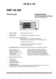
Example of heating optimization<br />
Contolled variable<br />
Optimization at<br />
startup<br />
Start optimization<br />
Example of cooling optimization<br />
Controlled variable<br />
Optimization at<br />
startup<br />
Start optimization<br />
Setpoint value<br />
Optimization difference<br />
Correcting setpoint value<br />
Setpoint value<br />
Figure 6: Self-optimization examples<br />
8.6.1 Monitoring the optimization process:<br />
Correcting setpoint value<br />
Optimization difference<br />
<strong>DMP</strong> <strong>48</strong> <strong>AS</strong> Version: 033 Number of pages: 21 of 25<br />
<strong>DMP</strong> <strong>48</strong> <strong>AW</strong> Edition: 08.08.2006 A0e033.doc<br />
t<br />
t<br />
Controlled variable<br />
Optimization to setpoint value<br />
after control<br />
Controlled variable<br />
Start optimization<br />
Optimization to setpoint value<br />
after control<br />
Start optimization<br />
Setpoint value<br />
Correcting setpoint value<br />
Setpoint value<br />
Sollwert<br />
The diagrams show possible incorrect settings with suggestions as to how to correct them.<br />
t<br />
Correcting Hilfssollwert setpoint value<br />
t
DOLD GMBH <strong>Operating</strong> instructions <strong>DMP</strong> <strong>48</strong> <strong>AS</strong> / <strong>AW</strong><br />
X<br />
(°C)<br />
W<br />
X<br />
(°C)<br />
W<br />
X<br />
(°C)<br />
W<br />
Pb too small<br />
Control oscillating<br />
Ti too small<br />
Td too large<br />
Figure 7: Incorrect settings of the feedback parameters<br />
8.7 The information level:<br />
P Press for approx. 3 sec. to get display: " Cod "<br />
<strong>DMP</strong> <strong>48</strong> <strong>AS</strong> Version: 033 Number of pages: 22 of 25<br />
<strong>DMP</strong> <strong>48</strong> <strong>AW</strong> Edition: 08.08.2006 A0e033.doc<br />
100<br />
P Display: " inF "<br />
P Jump to information level<br />
Display: Parameter:<br />
"Pnr" Current program number<br />
"SEn" Sensor ID as in table<br />
t<br />
t<br />
t<br />
X<br />
(°C)<br />
W<br />
X<br />
(°C)<br />
W<br />
X<br />
(°C)<br />
W<br />
Optimum setting<br />
Optimum setting<br />
Optimum setting<br />
t<br />
t<br />
t<br />
X<br />
(°C)<br />
W<br />
X<br />
(°C)<br />
W<br />
X<br />
(°C)<br />
W<br />
Pb too large<br />
slow start-up<br />
and poor control<br />
Ti too large<br />
Td too small<br />
t<br />
t<br />
t
DOLD GMBH <strong>Operating</strong> instructions <strong>DMP</strong> <strong>48</strong> <strong>AS</strong> / <strong>AW</strong><br />
Sensor ID:<br />
Sensor<br />
ID:<br />
ID by ordering<br />
key:<br />
Sensor: Max. display<br />
range:<br />
Max. setpoint<br />
range:<br />
<strong>DMP</strong> <strong>48</strong> <strong>AS</strong> Version: 033 Number of pages: 23 of 25<br />
<strong>DMP</strong> <strong>48</strong> <strong>AW</strong> Edition: 08.08.2006 A0e033.doc<br />
Display:<br />
P 1 P 1 Pt 100 -69...149°C -50...100°C 3 digits<br />
P 2 P 2 Pt 100 -69...249°C -50...200°C 3 digits<br />
P 3 P 3 Pt 100 -69...349°C -50...300°C 3 digits<br />
P 4 P 4 Pt 100 -69...699°C -50...600°C 3 digits<br />
P 5 P 5 Pt 100 -169...149°C -150...100°C 4 digits<br />
tL1 L 1 Fe-CuNi Type L -24...499°C 0...450°C 3 digi ts<br />
tL2 L 2 Fe-CuNi Type L -24...899°C 0...850°C 3 digi ts<br />
tn1 K 1 Ni Cr-Ni Type K -24...649°C 0...600°C 3 dig its<br />
tn2 K 2 Ni Cr-Ni Type K -24...1299°C 0...1200°C 4 d igits<br />
9. Line compensation, zero-point offset:<br />
9.1 Line compensation:<br />
Line compensation is required only with resistance thermometers in two-wire technology. Line<br />
resistance can be counterbalanced with the "Cor" parameter (configuration level).<br />
Proceed as follows to generate line compensation:<br />
1. Connect a 100 Ω resistor to the end of the sensor line (corresponds to 0°C).<br />
2. Read off the actual value from the display.<br />
3. Jump to the configuration level.<br />
4. Correct line resistance (display in °C) with the "Cor" parameter.<br />
Example: 1. Displayed actual value: +3.0°C<br />
2. "Cor" value to be set on the configuration level: -3.0°C<br />
3. Confirm the set value with the P key.<br />
Return to operating mode<br />
4. Display of actual value: 0.0°C<br />
5. Remove 100 Ω resistor from end of line.<br />
9.2 Zero-point offset:<br />
The "Cor" parameter can also be used for zero-point offset (offset value) towards plus or minus<br />
(as in the above example).
DOLD GMBH <strong>Operating</strong> instructions <strong>DMP</strong> <strong>48</strong> <strong>AS</strong> / <strong>AW</strong><br />
10. Error messages:<br />
10.1 Error messages (display):<br />
Error display: Cause: Remedy / Explanation:<br />
Er. 1 Pt 100 input: Sensor short circuit or<br />
Lower range limit exceeded,<br />
Sensor breakage or<br />
Upper range limit exceeded.<br />
Er. 1 Thermal converter input:<br />
Sensor breakage or<br />
Upper range limit exceeded,<br />
Sensor poles reversed or<br />
Upper range limit, exceeded<br />
Ambient temperature<br />
of controller > 70°C.<br />
<strong>DMP</strong> <strong>48</strong> <strong>AS</strong> Version: 033 Number of pages: 24 of 25<br />
<strong>DMP</strong> <strong>48</strong> <strong>AW</strong> Edition: 08.08.2006 A0e033.doc<br />
Check sensor<br />
Check sensor<br />
Check ambient temperature<br />
of controller<br />
Er. 9 System error Switch unit off/on<br />
11. Program version:<br />
Current program version:<br />
0 33 A0<br />
factory number<br />
current program number<br />
unit-specific number<br />
• Version 032: Status: 26.01.95 Basic version: Single-channel controller (twopoint<br />
controller, continuousaction<br />
controller) with analog<br />
output and logic input.<br />
• Version 033: Status: 14.02.95 Logic input function expanded: Programming<br />
block, sensor ID changed.<br />
12. Immunity:<br />
The immunity of the unit was tested with the following interference simulators manufactured by<br />
the Schaffner Company (Switzerland).
DOLD GMBH <strong>Operating</strong> instructions <strong>DMP</strong> <strong>48</strong> <strong>AS</strong> / <strong>AW</strong><br />
• NSG 222A: Interference pulses with broadband spectrum, short build-up time and low<br />
energy<br />
Test values: pulse amplitude ± 2500 V<br />
Rise time: 5 nsec.<br />
Symmetrical and asymmetric feed<br />
• NSG 225A: Interference pulse package with broad interference spectrum<br />
Test values: Stage 3: 2000 V<br />
Repetition frequency: 5 kHz<br />
• NSG 203A: Testing after power outages<br />
Test values: at 100% supply voltage dip: 50 msec.<br />
Repetition frequency: 1 Hz.<br />
<strong>DMP</strong> <strong>48</strong> <strong>AS</strong> Version: 033 Number of pages: 25 of 25<br />
<strong>DMP</strong> <strong>48</strong> <strong>AW</strong> Edition: 08.08.2006 A0e033.doc