Operating Instructions DMP 96 C Multi-channel ... - Dold GmbH
Operating Instructions DMP 96 C Multi-channel ... - Dold GmbH
Operating Instructions DMP 96 C Multi-channel ... - Dold GmbH

Create successful ePaper yourself
Turn your PDF publications into a flip-book with our unique Google optimized e-Paper software.
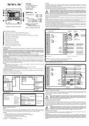
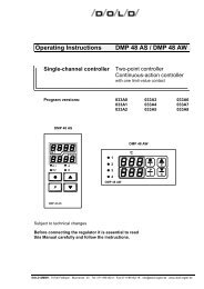
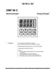
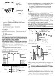
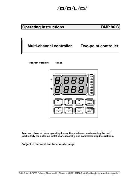
<strong>Operating</strong> <strong>Instructions</strong> <strong>DMP</strong> <strong>96</strong> C<br />
<strong>Multi</strong>-<strong>channel</strong> controller Two-point controller<br />
Program version: 11535<br />
°C<br />
°C<br />
1 2 3<br />
∗ P<br />
4 5<br />
Scan<br />
Static<br />
Read and observe these operating instructions before commissioning the unit<br />
(particularly the notes on installation, assembly and commissioning instructions).<br />
Subject to technical and functional change<br />
<strong>Dold</strong> <strong>GmbH</strong>, D70736 Fellbach, Blumenstr.33, Phone +49(0)711 95152-0, info@dold-regler.de, www.dold-regler.de<br />
Tune<br />
6<br />
1<br />
2<br />
3<br />
4<br />
5<br />
6<br />
7<br />
Start<br />
Stop
DOLD <strong>GmbH</strong> <strong>Operating</strong> <strong>Instructions</strong> <strong>DMP</strong> <strong>96</strong> C<br />
Index:<br />
1. The installation of the unit: .................................................................................. 3<br />
1.1 General: ........................................................................................................................................3<br />
1.2 Please note during installation:.....................................................................................................3<br />
1.3 Identification plate: ........................................................................................................................4<br />
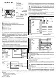
1.4 Terminal connection diagram:.......................................................................................................5<br />
1.5 Mechanical data:...........................................................................................................................5<br />
2. Inputs, technical data: .......................................................................................... 5<br />
2.1 Inputs <strong>channel</strong> 1 to <strong>channel</strong> 4:......................................................................................................5<br />
2.2 Possible inputs <strong>channel</strong> 1 to <strong>channel</strong> 4: .......................................................................................5<br />
2.3 Logic inputs ...................................................................................................................................6<br />
2.4 Technical data of the inputs:.........................................................................................................6<br />
2.4.1 Error-handling at inputs:.............................................................................................................6<br />
3. Controller character:............................................................................................. 7<br />
4. Outputs: ................................................................................................................. 7<br />
4.1 Potential-free relay contacts: ........................................................................................................7<br />
4.2 Logic outputs (optional):................................................................................................................7<br />
4.3 Output responses in cases of error:..............................................................................................7<br />
4.4 Optional analogue outputs (only valid for optional plug in PCB "C"): ...........................................8<br />
5. Auxiliary power: .................................................................................................... 8<br />
6. Display: .................................................................................................................. 8<br />
6.1 Upper 7-segment display:.............................................................................................................8<br />
6.2 Lower 7-segment display:.............................................................................................................9<br />
6.3 LED's:............................................................................................................................................9<br />
7. Operation:.............................................................................................................. 9<br />
7.1 The Different levels: ....................................................................................................................11<br />
7.2 Operation level:...........................................................................................................................12<br />
7.3 Extended Operation level:...........................................................................................................13<br />
7.3.1 Unlocking the limit contacts: ....................................................................................................14<br />
7.4 Configuration level: .....................................................................................................................14<br />
7.5 Parametrication level: .................................................................................................................17<br />
7.6 Self-tuning: ..................................................................................................................................21<br />
7.6.1 Monitoring the optimization process: .......................................................................................22<br />
8. Line Balancing, Zero Point Correction:............................................................. 23<br />
9. Error and Faults: ................................................................................................. 23<br />
9.1 List of possible error messages (display): ..................................................................................23<br />
10. Program version: .............................................................................................. 23<br />
11. Immunity:........................................................................................................... 25<br />
Supplement A: The serial interface (RS 485)<br />
(only for units with serial interface RS-485).<br />
Version: 115 Date: 08/2007 No. of pages: 25<br />
35E115B 07.doc<br />
2
DOLD <strong>GmbH</strong> <strong>Operating</strong> <strong>Instructions</strong> <strong>DMP</strong> <strong>96</strong> C<br />
1. The installation of the unit:<br />
1.1 General:<br />
The unit <strong>DMP</strong> <strong>96</strong> C is a microprocessor controlled multi <strong>channel</strong> controller. The unit is obtainable<br />
in different devices. It contains 2 to 4 <strong>channel</strong>s and between 0 and 8 freely configurable relays.<br />
The regulation function is configurable for each <strong>channel</strong>. In the following the maximum<br />
equipment with 4 <strong>channel</strong>s and 8 freely configurable relays is described. At slighter equipment<br />
the parameters, which do not refer to available parts, are not adjustable. The unit may be<br />
served only by competent personnel.<br />
1.2 Please note during installation:<br />
Important: These directions for the installation of<br />
DOLD devices have to be adhered to:<br />
If these directions are not adhered to the device may not work accurately, be destroyed<br />
or it may result in data being lost.<br />
Read all directions carefully before connecting the device.<br />
Connection to be carried out only by experts.<br />
This device is not a safety device. Safety devices have to be installed according to the relevant<br />
directions for use.<br />
Check if the power-supply voltage corresponds to rated voltage indicated on the identification<br />
plate before connecting and putting the device into operation. Fluctuations in the main voltage<br />
are only admissible within the indicated limits (specifications/identification plate).<br />
The described device is designated for the installation of switchboards.<br />
Electrical connections are to be carried out according to the connecting plan and the directions<br />
of the local electric supply company or the relevant regulations of the VDE respectively.<br />
Other consumers must not be connected to the mains terminals.<br />
In the event of mains interruptions, which lead to a malfunctioning of the device, relevant measures<br />
must be taken to avoid interruptions or interruptions must be filtered out by an external<br />
hum eliminator. The device is equipped with an internal hum eliminator.<br />
On installation the sensor lines have to be shielded. The screen must be single-ended. With regard<br />
to thermocouple pick-ups the compensating lead has to be laid as far as the control terminals.<br />
The device and inductive consumers as well as sensor lines/signal lines and high tension<br />
lines have to be placed in such a way that any mutual interference is excluded (placed separately;<br />
not parallely laid). go-and-return lines should be laid parallely and, if possible, twisted.<br />
Non-insulated sensors of a multi-<strong>channel</strong> control have to be adjusted to the same potential<br />
(max. potential difference: ±3.5 V eff.). Otherwise insulated sensors must be used (Warning:<br />
Ceramics insulations (Al-Oxide) can be conducting ≥400 °C).<br />
Post-connected contactors have to be equipped with RC protective allocations according to the<br />
manufacturer's instructions. If an internal protective allocation is mentioned in the connection<br />
plan of the device this has to be taken into account in the event of external allocation. If external<br />
allocation is missing short-term voltage peaks may result which lead to faster contact wear and<br />
may cause interference.<br />
The preadjustment of all parameters has to be checked during operation and adjusted to the local<br />
conditions (installation)! Wrongly adjusted parameters may cause serious malfunctions!<br />
Version: 115 Date: 08/2007 No. of pages: 25<br />
35E115B 07.doc<br />
3
DOLD <strong>GmbH</strong> <strong>Operating</strong> <strong>Instructions</strong> <strong>DMP</strong> <strong>96</strong> C<br />
Not all controlled systems can be controlled by parameters measured by means of selfoptimising;<br />
therefore, on principle, control response is to be checked for stability.<br />
The load circuits of the relays have to be protected against excessive currents in order to avoid<br />
the relay contacts becoming welded together.<br />
The device must not be installed in an ex-area.<br />
If used for purposes other than originally intended the device may be damaged and cause damage<br />
to connected installations.<br />
The life time of the relays is limited to 10 6 switching cycles at a load of 500 VA. Thus it is to a<br />
high degree dependent on the frequency of switching cycles.<br />
Time per switching cycle Time after which 10 6 switching cycles are reached<br />
(operation: 8 hours/day at a load of 500 VA)<br />
2 minutes about 11.4 years<br />
60 s about 5.7 years<br />
30 s about 2.8 years<br />
This table is invalid for Solid-State-Relay.<br />
At low loads life time increases with regard to the values indicated in the table.<br />
The device is to be protected against moisture (especially condensing moisture) and excessive<br />
contamination. If this is not assured the device is liable to malfunctions.<br />
Unplug connecting plugs only longitudinally to plug direction. Under no circumstances must the<br />
connecting plugs be plugged in or out obliquely!<br />
Furthermore care must be taken that the surrounding temperature corresponds to the values<br />
shown in the specifications. Sufficient air circulation must be provided.<br />
These operating instructions do not contain all directions to regulations, standards etc. which<br />
become effective when using this device in connection with other installations. These regulations,<br />
standards etc. must be ascertained and abided to by the purchaser.<br />
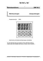
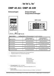
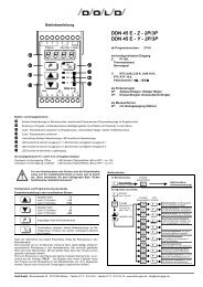
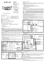
1.3 Identification plate:<br />
When making technical enquiries<br />
the following details are important<br />
unit type<br />
works number<br />
model number<br />
program version<br />
unit type<br />
operating volts:<br />
switching volts:<br />
works number:<br />
inputs:<br />
outputs:<br />
model number<br />
<strong>DMP</strong> <strong>96</strong> C<br />
Betriebsspannung<br />
Schaltleistung:<br />
Fabriknummer:<br />
Eingänge:<br />
Ausgänge:<br />
Ausf. Nr.: 850XXX<br />
Figure 1: Identification plate <strong>DMP</strong> <strong>96</strong> C<br />
Version: 115 Date: 08/2007 No. of pages: 25<br />
35E115B 07.doc<br />
ASP 675 XXX<br />
Terminal connection diagram number<br />
XXX V +/-10%<br />
according to order<br />
500 VA bei 230 V AC<br />
XXXXXX PXXFXXHXX<br />
500 VA at 230 V AC<br />
XXXXX according to order<br />
Relaisausgänge<br />
Logikausgänge<br />
Programmrelay<br />
outputs<br />
logic outputs<br />
according to order<br />
version: XXXXX program version<br />
4
DOLD <strong>GmbH</strong> <strong>Operating</strong> <strong>Instructions</strong> <strong>DMP</strong> <strong>96</strong> C<br />
1.4 Terminal connection diagram:<br />
The connection diagram shows maximum terminal assignment for the controller when all connection<br />
possibilities are used. The appropriate terminal assignment (depending of the type of<br />
controller used) can be found in the accompanying connection diagram.<br />
Connection diagram number according to identification plate: ASP 675XXX<br />
1.5 Mechanical data:<br />
Protection class: II<br />
Isolation group: C as per DIN VDE 0110 b<br />
Type of protection: As per DIN VDE 0470 (replaces DIN 40 050)<br />
EN 60 529 / IEC 529<br />
Front panel: IP 50 (optionally: IP 54 with the proper<br />
mounting and a suitable sealing ring)<br />
Housing: IP 30<br />
Connections: IP 20<br />
Housing: Pull-out housing for mounting control panel as per DIN 43 700<br />
with a B fastener as per DIN 43 835 (M 4 screw clamp)<br />
Material: PPO, glass-fiber reinforced (Noryl GFN2SE1), selfextinguishing,<br />
non-dripping, fire protection class UL 94 V1<br />
Front panel dimensions: <strong>96</strong> x <strong>96</strong> mm DIN 43 700<br />
Control panel cutout: 92 +0.8 x 92 +0.8 mm<br />
Recess depth: approx. 148 mm including screwed plug<br />
Terminal connections: Screwed socket strips, nominal cross section 2.5 mm 2<br />
Weight: approx. 420 g<br />
Ambient conditions: <strong>Operating</strong> temperature range: 0...+50°C<br />
Storage temperature range: -30...+70°C<br />
Climatic utilization category: as per DIN 40 040,<br />
corresponding to 75% relative humidity without moisture<br />
condensation<br />
2. Inputs, technical data:<br />
2.1 Inputs <strong>channel</strong> 1 to <strong>channel</strong> 4:<br />
• according to order<br />
• according to identification plate.<br />
2.2 Possible inputs <strong>channel</strong> 1 to <strong>channel</strong> 4:<br />
• Pt 100: Range: -100...600°C<br />
• Pt 100: Range: -200...100°C<br />
Pt 100: input 1 and 2 in three wire lead,<br />
input 3 and 4 in two wire lead<br />
• thermocouple Fe-CuNi: Range: 0...800°C<br />
• thermocouple Ni-CrNi: Range: 0...1200°C<br />
• standard signal voltage<br />
• standard signal current<br />
• mix of different inputs is possible<br />
Version: 115 Date: 08/2007 No. of pages: 25<br />
35E115B 07.doc<br />
5
DOLD <strong>GmbH</strong> <strong>Operating</strong> <strong>Instructions</strong> <strong>DMP</strong> <strong>96</strong> C<br />
• other inputs on demand<br />
2.3 Logic inputs<br />
Logic inputs controlled with external, potential-free contacts, contact voltage approx. 5 V DC<br />
Logic input 5: no function<br />
Logic input 6: no function<br />
Logic input 7: Start / Stop - function, controlled by level or by slope (configurable)<br />
2.4 Technical data of the inputs:<br />
Pt 100: Sensor current: constant 1 mA DC<br />
Calibration precision: ≤ 0,15 % F.S.<br />
Linearity error: ≤ 0,1% F.S.<br />
Temperature drift characteristics: ≤ 100 ppm/K<br />
Equipped with sensor breakage cutoff and short circuit fuse<br />
Pt 100 three-wire lead: Automatic line resistance compensation via software<br />
(maximum permissible line resistance: 50 Ω per lead)<br />
Pt 100 two-wire lead: Line resistance correction (line compensation) of maximum 11 Ω<br />
possible via software<br />
thermocouple: Calibration precision: ≤ 0.15% F.S.<br />
Linearity error: ≤ 0.15% F.S.<br />
Temperature drift characteristics<br />
(without reference point compensation): ≤ 80 ppm/K<br />
Effect of line resistance: ≤ 2μV/Ω<br />
Reference point compensation<br />
Error recognition using a controller reference point > 70°C<br />
Sensor breakage cutoff<br />
standard signal: Calibration precision: ≤ 0.15% F.S.<br />
Linearity error: ≤ 0,1% F.S.<br />
Temperature drift characteristics: ≤ 100 ppm/K<br />
standard signal current: input impedance: Ri = 100 Ω<br />
standard signal voltage: input impedance: Ri ≥ 10 kΩ<br />
General: Measurement cycle: 1 s<br />
Resolution:<br />
RC and diode protection circuit for each input<br />
≥ 14 bit<br />
Measuring-circuit monitoring: Error shown on display<br />
Protective circuits: Hardware watchdog and power-fail<br />
Data backup: EPROM, semiconductor storage,<br />
Hardware-protected calibrated values.<br />
2.4.1 Error-handling at inputs:<br />
If the input signal is leaving the measurement range around more than approx. 10% (according<br />
to chapters 2.2), it will be recognized as an error and indicated in the display. The regulation of<br />
the corresponding entrance is stopped and the outputs, which are associated to this entrance,<br />
according to the configuration activates or deactivates.<br />
Version: 115 Date: 08/2007 No. of pages: 25<br />
35E115B 07.doc<br />
6
DOLD <strong>GmbH</strong> <strong>Operating</strong> <strong>Instructions</strong> <strong>DMP</strong> <strong>96</strong> C<br />
3. Controller character:<br />
The controller character of <strong>channel</strong> 1 to <strong>channel</strong> 4 is configurable:<br />
• two point controller for heating with adjustable hysteresis<br />
• two point controller for cooling with adjustable hysteresis<br />
• two point controller for heating with PID controller characteristics<br />
• two point controller for cooling with PID controller characteristics<br />
4. Outputs:<br />
Outputs as per identification plate and accompanying terminal connection diagram:<br />
4.1 Potential-free relay contacts:<br />
Contact load: ≤ 250 V AC, ≤ 8 A resistive load<br />
at 500 VA typically 10 6 switching cycles<br />
K 1 to K 4, K 6, K 8: configurable relay outputs, make contact<br />
K 5, K 7: configurable relay outputs, change over<br />
K 9: relay output, change over,<br />
alarm contact, active in case of a sensor fault <strong>channel</strong> 1 to <strong>channel</strong> 4<br />
(fault-messages 10, 11, 12, 13) or in case a hardware fault (faultmessages<br />
30, 31, 32)<br />
The amount of available relays can be ordered between 1 and 8 relays. The controller functions<br />
and limit values functions are freely distributable to the available amount relays.<br />
Please note: Alarm contact K 9 and relay contacts (limit contacts K 1 to K 8), which<br />
are inserted as alarm contacts, offer no protection against all possibilities<br />
of errors. If necessary the employment recommends itself a further,<br />
independent checking equipment.<br />
4.2 Logic outputs (optional):<br />
Logic outputs for activating solid-state relays, (in place of relay outputs K 1 to K 4):<br />
Open collector, not galvanically separated, short-circuit-proof,<br />
typically: 0/10 V DC, maximum: 20 mA.<br />
4.3 Output responses in cases of error:<br />
Output response of the outputs K 1 to K 8 in cases of sensor error:<br />
• the regulation of the faulty <strong>channel</strong> will be stopped<br />
• outputs, which are associated to the faulty <strong>channel</strong> takes off the defined status to the configuration<br />
(configuration level)<br />
• approx. 20 s after removal of the error, the error message is picked up and the relay function<br />
is released again<br />
• the <strong>channel</strong>s and relays who are not affected works continue duly.<br />
Version: 115 Date: 08/2007 No. of pages: 25<br />
35E115B 07.doc<br />
7
DOLD <strong>GmbH</strong> <strong>Operating</strong> <strong>Instructions</strong> <strong>DMP</strong> <strong>96</strong> C<br />
4.4 Optional analogue outputs (only valid for optional plug in PCB "C"):<br />
Voltage or current output according to purchase order (ranges according to configuration):<br />
Output 1: actual value output of range of <strong>channel</strong> 1<br />
Output 2: actual value output of range of <strong>channel</strong> 2<br />
Output 3: actual value output of range of <strong>channel</strong> 3<br />
5. Auxiliary power:<br />
Auxiliary power (operating voltage) as per identification plate:<br />
Standard: 230 V AC (±10%), 48...62 Hz,<br />
Power consumption, depending on model: ≤ 15 VA,<br />
Not affected by voltage fluctuations within the defined range.<br />
6. Display:<br />
6.1 Upper 7-segment display:<br />
shows according to status of controller:<br />
6.1.1 after pushing the according operating key:<br />
1 Channel number 1 and actual value <strong>channel</strong> 1<br />
2 Channel number 2 and actual value <strong>channel</strong> 2<br />
3 Channel number 3 and actual value <strong>channel</strong> 3<br />
∗<br />
4<br />
Channel number 4 and actual value <strong>channel</strong> 4<br />
6.1.2. Scan - mode: switching automatically from <strong>channel</strong> to <strong>channel</strong> showing<br />
actual values and <strong>channel</strong> number one after another<br />
6.1.3. Static - mode: after pushing two <strong>channel</strong> number keys at the same time,<br />
the first actual value with its <strong>channel</strong> number is on display<br />
6.1.4. Parameter symbols in input mode.<br />
Version: 115 Date: 08/2007 No. of pages: 25<br />
35E115B 07.doc<br />
8
DOLD <strong>GmbH</strong> <strong>Operating</strong> <strong>Instructions</strong> <strong>DMP</strong> <strong>96</strong> C<br />
6.2 Lower 7-segment display:<br />
shows according to status of controller:<br />
6.2.1. after pushing the according operating key:<br />
6.3 LED's:<br />
1 set point value <strong>channel</strong> 1 (without <strong>channel</strong> number)<br />
2 set point value <strong>channel</strong> 2 (without <strong>channel</strong> number)<br />
3 set point value <strong>channel</strong> 3 (without <strong>channel</strong> number)<br />
∗<br />
4<br />
set point value <strong>channel</strong> 4 (without <strong>channel</strong> number)<br />
6.2.2. Scan - mode: set point display (without <strong>channel</strong> number)<br />
6.2.3. Static - mode: after pushing two <strong>channel</strong> number keys at the same time, the<br />
second actual value with its <strong>channel</strong> number is on display<br />
6.2.4. Parameter symbols in input mode (4 digits).<br />
LED 1 yellow lights up when output K 1 is active<br />
LED 2 yellow lights up when output K 2 is active<br />
LED 3 yellow lights up when output K 3 is active<br />
LED 4 yellow lights up when output K 4 is active<br />
LED 5 yellow lights up when output K 5 is active<br />
LED 6 yellow lights up when output K 6 is active<br />
LED 7 yellow lights up when output K 7 is active<br />
LED 8 red Scan / Static lights up in Scan - mode<br />
LED 9 red Start / Stop lights up when controller has been started.<br />
7. Operation:<br />
The program structure of the <strong>DMP</strong> <strong>96</strong> C controller has four clearly defined levels:<br />
• the Operation level to alter set point values<br />
• the Extended Operation level to alter limit contact outputs (optional)<br />
• the Parametrication level to adapt the control parameters to the regulation requirements<br />
and set point value ranges<br />
• the Configuration level to set up the line balance, the controller character, the error allocations,<br />
the interface (optional) and the limit contacts (optional).<br />
Version: 115 Date: 08/2007 No. of pages: 25<br />
35E115B 07.doc<br />
9
DOLD <strong>GmbH</strong> <strong>Operating</strong> <strong>Instructions</strong> <strong>DMP</strong> <strong>96</strong> C<br />
Setting parameters on the various levels:<br />
1<br />
1 and 2<br />
3<br />
3 and 2<br />
P<br />
5<br />
current value: +1<br />
current value: +10<br />
after 3 s: +100<br />
current value: -1<br />
current value: -10<br />
after 3 s: -100<br />
the value on display is entered.<br />
After confirming the last parameter, return to normal operating mode.<br />
If no key is pressed within 10 seconds, automatic return to normal operating mode, without accepting<br />
the changed parameters.<br />
To activate the regulation:<br />
Start<br />
Stop<br />
To activate self-tuning 1) :<br />
Tune<br />
6<br />
this key will enable or disable the regulation, providing the Start/Stop key is not<br />
disabled in the configuration level.<br />
To start or stop the self-tune operation in the respective <strong>channel</strong> set for with<br />
parameter "t.ch" 1) see 7.6. self-tuning.<br />
Start up the self-tuning is only possible, if to the discontinued <strong>channel</strong> also at least one relay is<br />
configured as controller output on this <strong>channel</strong>.<br />
Display mode:<br />
Scan<br />
Static<br />
Scan - mode: automatic display switch from one <strong>channel</strong> to the other for<br />
actual and set point values of all <strong>channel</strong>s.<br />
Static - mode: After pressing a <strong>channel</strong> select key the according actual <strong>channel</strong><br />
and set point value will appear on display.<br />
Version: 115 Date: 08/2007 No. of pages: 25<br />
35E115B 07.doc<br />
After pressing the same time two of the according <strong>channel</strong> select<br />
keys the according actual values are switched into the<br />
displays.<br />
10
DOLD <strong>GmbH</strong> <strong>Operating</strong> <strong>Instructions</strong> <strong>DMP</strong> <strong>96</strong> C<br />
7.1 The Different levels:<br />
P<br />
5<br />
P<br />
5<br />
1 1<br />
3<br />
press for short time<br />
to push for about 3 s<br />
Figure 2: The various levels<br />
Version: 115 Date: 08/2007 No. of pages: 25<br />
35E115B 07.doc<br />
P<br />
5<br />
Code<br />
100<br />
Code<br />
72<br />
Code<br />
155<br />
Code<br />
55<br />
Code<br />
109<br />
Operation level<br />
3<br />
and<br />
and<br />
Extended Operation level<br />
Configuration level<br />
Parametrication level<br />
Unlocking of the limit contacts<br />
2<br />
2<br />
11
DOLD <strong>GmbH</strong> <strong>Operating</strong> <strong>Instructions</strong> <strong>DMP</strong> <strong>96</strong> C<br />
7.2 Operation level:<br />
Set point adjustments:<br />
P<br />
5<br />
press for short time and jump to operation level<br />
Range: Parameter: Display: Works setting:<br />
" 1.rdo "..." 1.ruP " Common set point<br />
for <strong>channel</strong> 1 to <strong>channel</strong> 4<br />
(if configuration "4.SPt" = 0)<br />
Version: 115 Date: 08/2007 No. of pages: 25<br />
35E115B 07.doc<br />
" SP.1 " 0.0°C<br />
" 1.rdo "..." 1.ruP " Set point <strong>channel</strong> 1 " SP.1 " 0.0°C<br />
" 2.rdo "..." 2.ruP " Set point <strong>channel</strong> 2 " SP.2 " 0.0°C<br />
" 3.rdo "..." 3.ruP " Set point <strong>channel</strong> 3 " SP.3 " 0.0°C<br />
" 4.rdo "..." 4.ruP " Set point <strong>channel</strong> 4<br />
" SP.4 " 0.0°C<br />
0...4 Self-tuning for <strong>channel</strong> 1 to <strong>channel</strong> 4<br />
0: no self-tuning possible for <strong>channel</strong> 1<br />
to <strong>channel</strong> 4<br />
(Channel adjustment only possible if<br />
parameter "no.t" = 0,<br />
see parametrication level)<br />
(parameter only can be activated if<br />
regulation output is set for PID -<br />
control characteristic)<br />
" t.ch " 0<br />
12
DOLD <strong>GmbH</strong> <strong>Operating</strong> <strong>Instructions</strong> <strong>DMP</strong> <strong>96</strong> C<br />
7.3 Extended Operation level:<br />
Adjustment of the set point values of the configurable limit contacts:<br />
Set point values setting is only possible, when corresponding output is configured for limit contact.<br />
P<br />
5<br />
display to show: " Cod "<br />
100<br />
Key in code number: Code 72 with the keys<br />
Range: Parameter: Display: Works setting:<br />
"rdo" ... "rup"<br />
(in dependent of<br />
the selected chan-<br />
nel)<br />
Set point value or spreading of the<br />
limit contact<br />
Version: 115 Date: 08/2007 No. of pages: 25<br />
35E115B 07.doc<br />
" x.Li X "<br />
x: 1-8<br />
X: depending upon<br />
configuration<br />
"Li " limit contact absolute make contact<br />
"Li " limit contact absolute break contact<br />
"Li " limit contact relative to minus make<br />
contact<br />
"Li " limit contact relative to minus break<br />
contact<br />
"Li " limit contact relative to plus make<br />
contact<br />
"Li " limit contact relative to plus break<br />
contact<br />
"Li " limiting comparator make contact<br />
"Li " limiting comparator break contact<br />
"LI " limit contact absolute make contact<br />
with locking<br />
"LI " limit contact absolute break contact<br />
with locking<br />
"LI " limit contact relative to minus make<br />
contact with locking<br />
"LI " limit contact relative to minus break<br />
contact with locking<br />
"LI " limit contact relative to plus make<br />
contact with locking<br />
"LI " limit contact relative to plus break<br />
contact with locking<br />
"LI " limiting comparator make contact with<br />
locking<br />
"LI " limiting comparator break contact with<br />
locking<br />
0.5...50.0°C hysteresis limit contact " x.HYS "<br />
x: 1 - 8<br />
20.0°C<br />
1.0 °C<br />
13
DOLD <strong>GmbH</strong> <strong>Operating</strong> <strong>Instructions</strong> <strong>DMP</strong> <strong>96</strong> C<br />
7.3.1 Unlocking the limit contacts:<br />
After setting the code number the configured limit contacts can be unlocked.<br />
P<br />
5<br />
display to show: " Cod "<br />
100<br />
Key in code number: Code 109<br />
P<br />
5<br />
7.4 Configuration level:<br />
P<br />
5<br />
code number confirmed, enter to operation level<br />
display to show: " Cod "<br />
Version: 115 Date: 08/2007 No. of pages: 25<br />
35E115B 07.doc<br />
100<br />
Key in code number: Code 155 with the keys:<br />
or<br />
1<br />
1<br />
and<br />
current value +1<br />
2<br />
3 current value -1<br />
3 and<br />
P<br />
5<br />
2<br />
current value +10 after about 3 s +100<br />
current value -10 after about 3 s -100<br />
code number confirmed, jump to configuration level<br />
Range: Parameter: Display: Works setting:<br />
1...20 Low-pass filter,<br />
cycle time always is 1 s<br />
" ti.Fi " 3<br />
1: direct measurement<br />
2: two measurements are averaged<br />
2...maximum num-<br />
20: 20 measurements are averaged<br />
standard preadjustment is three,<br />
three measurements are averaged, the<br />
latest measure will be replaced<br />
Number of active <strong>channel</strong> "CH.no" according to<br />
ber of <strong>channel</strong><br />
order<br />
-30.0...+30.0°C Line balance <strong>channel</strong> 1, offset value " 1.Lin " 0.0°C<br />
will be added to actual value<br />
-30.0...+30.0°C Line balance <strong>channel</strong> 2, offset value<br />
will be added to actual value<br />
" 2.Lin " 0.0°C<br />
14
DOLD <strong>GmbH</strong> <strong>Operating</strong> <strong>Instructions</strong> <strong>DMP</strong> <strong>96</strong> C<br />
Range: Parameter: Display: Works setting:<br />
-30.0...+30.0°C Line balance <strong>channel</strong> 3, offset value<br />
will be added to actual value<br />
" 3.Lin " 0.0°C<br />
-30.0...+30.0°C Line balance <strong>channel</strong> 4, offset value<br />
will be added to actual value<br />
" 4.Lin " 0.0°C<br />
0...1 Standard signal <strong>channel</strong> 1,<br />
parameter only appears in configuration<br />
of standard signal<br />
" 1.i_4 " 0<br />
0: 0...20 mA or 0...10 V DC<br />
1: 4...20 mA or 2...10 V DC<br />
0...1 Standard signal <strong>channel</strong> 2,<br />
parameter only appears in configuration<br />
of standard signal<br />
" 2.i_4 " 0<br />
0: 0...20 mA or 0...10 V DC<br />
1: 4...20 mA or 2...10 V DC<br />
0...1 Standard signal <strong>channel</strong> 3,<br />
parameter only appears in configuration<br />
of standard signal<br />
" 3.i_4 " 0<br />
0: 0...20 mA or 0...10 V DC<br />
1: 4...20 mA or 2...10 V DC<br />
0...1 Standard signal <strong>channel</strong> 4,<br />
parameter only appears in configuration<br />
of standard signal<br />
" 4.i_4 " 0<br />
0: 0...20 mA or 0...10 V DC<br />
1: 4...20 mA or 2...10 V DC<br />
0...1 Set point <strong>channel</strong> 1 to <strong>channel</strong> 4 " 4.SPt " 1<br />
0: one common set point for<br />
<strong>channel</strong> 1 to <strong>channel</strong> 4<br />
1: separate set points for<br />
<strong>channel</strong> 1 to <strong>channel</strong> 4<br />
0...3 Configuration of controller type,<br />
controller output: <strong>channel</strong> 1<br />
" 1rtY " according to<br />
<strong>channel</strong> 2<br />
" 2rtY " order<br />
<strong>channel</strong> 3<br />
" 3rtY "<br />
<strong>channel</strong> 4<br />
" 4rtY "<br />
0: heating controller with PIDcharacter<br />
1: cooling controller with PIDcharacter<br />
2: cooling controller with hysteresis<br />
setting<br />
3: cooling controller with hysteresis<br />
setting<br />
0...28 Configuration relay 1 to relay 8 " rEL.1 " -<br />
" rEL.8 "<br />
5<br />
0; 6-8; 13-16; 21-24 no function (output deactivated)<br />
1: limit contact absolute, to close on<br />
rising temperature<br />
17: just as with locking<br />
2: limit contact tracking to minus, to<br />
close on rising temperature,<br />
18: just as with locking<br />
3: limit contact tracking to plus, to<br />
close on rising temperature,<br />
19: just as with locking<br />
Version: 115 Date: 08/2007 No. of pages: 25<br />
35E115B 07.doc<br />
15
DOLD <strong>GmbH</strong> <strong>Operating</strong> <strong>Instructions</strong> <strong>DMP</strong> <strong>96</strong> C<br />
Range: Parameter: Display: Works setting:<br />
4: limit comparator, closed in good<br />
band,<br />
20: just as with locking<br />
5: the output takes over the controller<br />
function heating or cooling belonging<br />
to the configured <strong>channel</strong><br />
9: limit contact absolute, to open on<br />
rising temperature,<br />
25: just as with locking<br />
10: limit contact tracking to minus, to<br />
open on rising temperature,<br />
26 just as with locking<br />
11: limit contact tracking to plus, to<br />
open on rising temperature,<br />
27 just as with locking<br />
12: limit comparator, open in good<br />
band<br />
28: just as with locking<br />
1 - 4 Channel selection for the corresponding<br />
output, the output works<br />
with the setting <strong>channel</strong><br />
1: <strong>channel</strong> 1<br />
2: <strong>channel</strong> 2<br />
3: <strong>channel</strong> 3<br />
4: <strong>channel</strong> 4<br />
0...2 Analogue output of actual value (optional)<br />
<strong>channel</strong> 1<br />
<strong>channel</strong> 2<br />
<strong>channel</strong> 3<br />
0: voltage 0...10 V DC<br />
current 0...20 mA<br />
1: voltage 0...5 V DC<br />
current 0...10 mA<br />
2: voltage 0...2 V DC<br />
current 0...4 mA<br />
3: voltage 2...10 V DC<br />
current 4...20 mA<br />
voltage / current according to order<br />
0...1 Automatic start - function<br />
0: no automatic start if controller is<br />
switched on<br />
1: controller automatically starts<br />
when switched on<br />
0...1 Start/stop - key - function<br />
0: normal start/stop-function via key<br />
1: no start/stop-function, controller<br />
automatically starts if switched on<br />
(independent of parameter "Auto")<br />
0...2 Start/stop - function with<br />
logic input 7<br />
0: no function<br />
1: controlled by level<br />
2 controlled by slope<br />
Version: 115 Date: 08/2007 No. of pages: 25<br />
35E115B 07.doc<br />
"r1.Ch" -<br />
"r8.Ch"<br />
" 1dAc "<br />
" 2dAc "<br />
" 3dAc "<br />
" Auto " 0<br />
" noSt " 0<br />
" Et.St " 0<br />
16
DOLD <strong>GmbH</strong> <strong>Operating</strong> <strong>Instructions</strong> <strong>DMP</strong> <strong>96</strong> C<br />
Range: Parameter: Display: Works setting:<br />
0...1 Display resolution<br />
0: without 1/10<br />
1: with 1/10<br />
0...1 Fault/error definitions<br />
0: output in case of fault disabled<br />
1: output in case of fault active<br />
output K 1<br />
output K 2<br />
output K 3<br />
output K 4<br />
output K 5<br />
output K 6<br />
output K 7<br />
output K 8<br />
Version: 115 Date: 08/2007 No. of pages: 25<br />
35E115B 07.doc<br />
"diSP" depending<br />
upon range<br />
" r1.FE "<br />
" r2.FE "<br />
" r3.FE "<br />
" r4.FE "<br />
" r5.FE "<br />
" r6.FE "<br />
" r7.FE "<br />
" r8.FE "<br />
0...<strong>96</strong> Baud rate<br />
" bAUd " 0<br />
0: interface disabled<br />
3: 300 Baud<br />
6: 600 Baud<br />
12: 1200 Baud<br />
24: 2400 Baud<br />
48: 4800 Baud<br />
<strong>96</strong>: <strong>96</strong>00 Baud<br />
1...32<br />
all other settings will result in 300 baud<br />
Device address " Adr " 1<br />
0...2 Parity<br />
" PAri " 0<br />
0: none<br />
1: odd<br />
2: even<br />
In case of parameter " 4.SPt " is reconfigured (one common set point or 4 different set<br />
points) the set point adjustments in the operation level have to be checked.<br />
Optional: in case of limit contactors are reconfigured its adjustments have to be checked<br />
in the extended operating level.<br />
7.5 Parametrication level:<br />
Setting of control parameters:<br />
P<br />
5<br />
display to show: " Cod "<br />
100<br />
Key in code number: Code 55 with the keys:<br />
or<br />
1<br />
1<br />
and<br />
current value +1<br />
2<br />
0<br />
0<br />
0<br />
0<br />
0<br />
0<br />
0<br />
0<br />
current value +10 after about 3 s +100<br />
17
DOLD <strong>GmbH</strong> <strong>Operating</strong> <strong>Instructions</strong> <strong>DMP</strong> <strong>96</strong> C<br />
3 current value -1<br />
3 and<br />
P<br />
5<br />
Version: 115 Date: 08/2007 No. of pages: 25<br />
35E115B 07.doc<br />
2<br />
current value -10 after about 3 s -100<br />
code number confirmed, jump to paramerication level<br />
Range: Parameter: Display: Works setting:<br />
0...30°C Tune difference from set point " t.di " 0.0°C<br />
0...1 Define self-tune <strong>channel</strong><br />
" no.t " 0<br />
0: self-tuning for <strong>channel</strong> 1 to 4<br />
1: disable the input of a self-tune<br />
<strong>channel</strong> "t.ch"<br />
0...60 s Scan - time display " Sc.t " 3<br />
According to the configuration of the controller outputs (according to the purchase order)<br />
only those parameters are on display which correspond to the according function!<br />
Function of controller:<br />
Two point controller with hysteresis setting<br />
Range: Parameter: Display: Works setting:<br />
according to purchase<br />
order or<br />
name plate<br />
according to purchase<br />
order or<br />
name plate<br />
Range start <strong>channel</strong> 1, range setting<br />
according to type of sensor; with input<br />
standard signal -200...1000 Digit<br />
Range end <strong>channel</strong> 1, range setting<br />
according to type of sensor; with input<br />
standard signal -200...1000 Digit<br />
" 1.rt_ "<br />
" 1.rt ─ "<br />
according to<br />
type of sensor<br />
according to<br />
type of sensor<br />
" 1.rt_ "..." 1.rt ─ " Lower set point limit <strong>channel</strong> 1 " 1.rdo " according to<br />
type of sensor<br />
" 1.rdo "..." 1.rt ─ " Upper set point limit <strong>channel</strong> 1 " 1.ruP " according to<br />
type of sensor<br />
0.2...10.0°C Switching hysteresis <strong>channel</strong> 1 " 1-HY " 0.5% of set<br />
point range<br />
according to pur- Range start <strong>channel</strong> 2, range setting " 2.rt_ " according to<br />
chase order or according to type of sensor; with input<br />
type of sensor<br />
name plate standard signal -200...1000 Digit<br />
according to purchase<br />
order or<br />
Range end <strong>channel</strong> 2, range setting<br />
according to type of sensor; with input<br />
" 2.rt<br />
name plate standard signal -200...1000 Digit<br />
─ " according to<br />
type of sensor<br />
" 2.rt_ "..." 2.rt ─ " Lower set point limit <strong>channel</strong> 2 " 2.rdo " according to<br />
type of sensor<br />
" 2.rdo "..." 2.rt ─ " Upper set point limit <strong>channel</strong> 2 " 2.ruP " according to<br />
type of sensor<br />
0.2...10.0°C Switching hysteresis <strong>channel</strong> 2 " 2-HY " 0.5% of set<br />
point range<br />
according to pur- Range start <strong>channel</strong> 3, range setting " 3.rt_ " according to<br />
chase order or according to type of sensor; with input<br />
type of sensor<br />
name plate standard signal -200...1000 Digit<br />
according to purchase<br />
order or<br />
Range end <strong>channel</strong> 3, range setting<br />
according to type of sensor; with input<br />
" 3.rt<br />
name plate standard signal -200...1000 Digit<br />
─ " according to<br />
type of sensor<br />
18
DOLD <strong>GmbH</strong> <strong>Operating</strong> <strong>Instructions</strong> <strong>DMP</strong> <strong>96</strong> C<br />
Range: Parameter: Display: Works setting:<br />
" 3.rt_ "..." 3.rt ─ " Lower set point limit <strong>channel</strong> 3 " 3.rdo " according to<br />
type of sensor<br />
" 3.rdo "..." 3.rt ─ " Upper set point limit <strong>channel</strong> 3 " 3.ruP " according to<br />
type of sensor<br />
0.2...10.0°C Switching hysteresis <strong>channel</strong> 3 " 3-HY " 0.5% of set<br />
point range<br />
according to pur- Range start <strong>channel</strong> 4, range setting " 4.rt_ " according to<br />
chase order or according to type of sensor; with input<br />
type of sensor<br />
name plate standard signal -200...1000 Digit<br />
according to purchase<br />
order or<br />
Range end <strong>channel</strong> 4, range setting<br />
according to type of sensor; with input<br />
" 4.rt<br />
name plate standard signal -200...1000 Digit<br />
─ " according to<br />
type of sensor<br />
" 4.rt_ "..." 4.rt ─ " Lower set point limit <strong>channel</strong> 4 " 4.rdo " according to<br />
type of sensor<br />
" 4.rdo "..." 4.rt ─ " Upper set point limit <strong>channel</strong> 4 " 4.ruP " according to<br />
type of sensor<br />
0.2...10.0°C Switching hysteresis <strong>channel</strong> 4 " 4-HY " 0.5% of set<br />
point range<br />
Two point controller with PID control characteristics:<br />
Range: Parameter: Display: Works setting:<br />
according to purchase<br />
order or<br />
name plate<br />
according to purchase<br />
order or<br />
name plate<br />
Range start <strong>channel</strong> 1, range setting<br />
according to type of sensor; with input<br />
standard signal -200...1000 Digit<br />
Range end <strong>channel</strong> 1, range setting<br />
according to type of sensor; with input<br />
standard signal -200...1000 Digit<br />
Version: 115 Date: 08/2007 No. of pages: 25<br />
35E115B 07.doc<br />
" 1.rt_ "<br />
" 1.rt ─ "<br />
according to<br />
type of sensor<br />
according to<br />
type of sensor<br />
" 1.rt_ "..." 1.rt ─ " Lower set point limit <strong>channel</strong> 1 " 1.rdo " according to<br />
type of sensor<br />
" 1.rdo "..." 1.rt ─ " Upper set point limit <strong>channel</strong> 1 " 1.ruP " according to<br />
type of sensor<br />
0.1...99.9% Proportional band <strong>channel</strong> 1<br />
Pb = 0.1...99.9% refer to<br />
range " 1.rt_ "..." 1.rt ─ "<br />
" 1-Pb" 10.0 %<br />
0...499 s Time derivative <strong>channel</strong> 1<br />
(set 0 = value 0)<br />
" 1-td " 100 s<br />
0...2000 s Time integral <strong>channel</strong> 1<br />
(set 0 = value 0)<br />
" 1-ti " 400 s<br />
0...100% Maximum integral <strong>channel</strong> 1 " 1-IE " 30 %<br />
2...60 s Cycle time <strong>channel</strong> 1 " 1 CY " 30 s relay<br />
5 s logic<br />
according to pur- Range start <strong>channel</strong> 2, range setting " 2.rt_ " according to<br />
chase order or according to type of sensor; with input<br />
type of sensor<br />
name plate standard signal -200...1000 Digit<br />
according to purchase<br />
order or<br />
Range end <strong>channel</strong> 2, range setting<br />
according to type of sensor; with input<br />
" 2.rt<br />
name plate standard signal -200...1000 Digit<br />
─ " according to<br />
type of sensor<br />
" 2.rt_ "..." 2.rt ─ " Lower set point limit <strong>channel</strong> 2 " 2.rdo " according to<br />
type of sensor<br />
" 2.rdo "..." 2.rt ─ " Upper set point limit <strong>channel</strong> 2 " 2.ruP " according to<br />
type of sensor<br />
19
DOLD <strong>GmbH</strong> <strong>Operating</strong> <strong>Instructions</strong> <strong>DMP</strong> <strong>96</strong> C<br />
Range: Parameter: Display: Works setting:<br />
0.1...99.9% Proportional band <strong>channel</strong> 2<br />
Pb = 0.1...99.9% refer to<br />
range " 2.rt_ "..." 2.rt ─ "<br />
" 2-Pb " 10.0 %<br />
0...499 s Time derivative <strong>channel</strong> 2<br />
(set 0 = value 0)<br />
" 2-td " 100 s<br />
0...2000 s Time integral <strong>channel</strong> 2<br />
(set 0 = value 0)<br />
" 2-ti " 400 s<br />
0...100% Maximum integral <strong>channel</strong> 2 " 2-IE " 30 %<br />
2...60 s Cycle time <strong>channel</strong> 2 " 2-CY " 30 s relay<br />
according to purchase<br />
order or<br />
name plate<br />
according to purchase<br />
order or<br />
name plate<br />
Range start <strong>channel</strong> 3, range setting<br />
according to type of sensor; with input<br />
standard signal -200...1000 Digit<br />
Range end <strong>channel</strong> 3, range setting<br />
according to type of sensor; with input<br />
standard signal -200...1000 Digit<br />
Version: 115 Date: 08/2007 No. of pages: 25<br />
35E115B 07.doc<br />
" 3.rt_ "<br />
" 3.rt ─ "<br />
5 s logic<br />
according to<br />
type of sensor<br />
according to<br />
type of sensor<br />
" 3.rt_ "..." 3.rt ─ " Lower set point limit channe 3 " 3.rdo " according to<br />
type of sensor<br />
" 3.rdo "..." 3.rt ─ " Upper set point limit <strong>channel</strong> 3 " 3.ruP " according to<br />
type of sensor<br />
0.1...99.9% Proportional band <strong>channel</strong> 3<br />
Pb = 0.1...99.9% refer to<br />
range " 3.rt_ "..." 3.rt ─ "<br />
" 3-Pb " 10.0 %<br />
0...499 s Time derivative <strong>channel</strong> 3<br />
(set 0 = value 0)<br />
" 3-td " 100 s<br />
0...2000 s Time integral <strong>channel</strong> 3<br />
(set 0 = value 0)<br />
" 3-ti " 400 s<br />
0...100% Maximum integral <strong>channel</strong> 3 " 3-IE " 30 %<br />
2...60 s Cycle time <strong>channel</strong> 3 " 3-CY " 30 s relay<br />
5 s logic<br />
according to pur- Range start <strong>channel</strong> 4, range setting " 4.rt_ " according to<br />
chase order or according to type of sensor; with input<br />
type of sensor<br />
name plate standard signal -200...1000 Digit<br />
according to purchase<br />
order or<br />
Range end <strong>channel</strong> 4, range setting<br />
according to type of sensor; with input<br />
" 4.rt<br />
name plate standard signal -200...1000 Digit<br />
─ " according to<br />
type of sensor<br />
" 4.rt_ "..." 4.rt ─ " Lower set point limit <strong>channel</strong> 4 " 4.rdo " according to<br />
type of sensor<br />
" 4.rdo "..." 4.rt ─ " Upper set point limit <strong>channel</strong> 4 " 4.ruP " according to<br />
type of sensor<br />
0.1...99.9% Proportional band <strong>channel</strong> 4<br />
Pb = 0.1...99.9% refer to<br />
range " 4.rt_ "..." 4.rt ─ "<br />
" 4-Pb" 10.0 %<br />
0...499 s Time derivative <strong>channel</strong> 4<br />
(set 0 = value 0)<br />
" 4-td " 100 s<br />
0...2000 s Time integral <strong>channel</strong> 4<br />
(set 0 = value 0)<br />
" 4-ti " 400 s<br />
0...100% Maximum integral <strong>channel</strong> 4 " 4-IE " 30 %<br />
2...60 s Cycle time <strong>channel</strong> 4 " 4-CY " 30 s relay<br />
5 s logic<br />
20
DOLD <strong>GmbH</strong> <strong>Operating</strong> <strong>Instructions</strong> <strong>DMP</strong> <strong>96</strong> C<br />
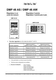
7.6 Self-tuning:<br />
For matching the regulator to the regulator path, the <strong>DMP</strong> <strong>96</strong> C is provided with a tuning facility.<br />
The tuning algorithm is based on modified Ziegler-Nichols rules, whereby the nominal data of<br />
the path are determined following an oscillation test in a closed control loop.<br />
These nominal data - in particular the oscillation cycle and amplitude - form the basis for calculating<br />
the relevant parameters.<br />
Initiation self-tuning:<br />
The tuning process can be activated at any time, if the controller has been started,<br />
by pressing the key<br />
Tune<br />
6 (5 seconds).<br />
Tuning is then effected on the <strong>channel</strong> selected by the parameter "t.ch".<br />
The tune facility must be cleared at the parametrication level.<br />
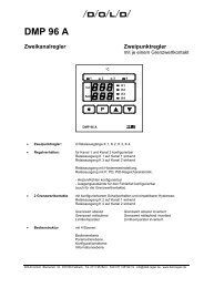
Tuning Example - heating<br />
Controlled variable Controlled variable<br />
Tuning on start-up<br />
Start of tuning<br />
Figure 3: Tuning example<br />
Set point<br />
Tuning variation<br />
Auxiliary set point<br />
Version: 115 Date: 08/2007 No. of pages: 25<br />
35E115B 07.doc<br />
t<br />
Tuning following regulation<br />
to set point<br />
Set point<br />
Start of tuning<br />
Auxiliary set point<br />
In the tuning procedure, the algorithm employs an auxiliary set point value, which diverges from<br />
the set point value by the amount preset in the parametrication level.<br />
Auxiliary set point = set point - "t.di"<br />
During the tuning procedure, the controller works with the P-regulating characteristic<br />
(Pb = 0,1%), and as an optical check, the set point and the "OPt" are shown alternately on the<br />
lower display.<br />
In order to calculate the parameters, the controller requires two oscillations following which it<br />
runs the control variable to the set point.<br />
Once the tuning procedure is finished, only the current set point appears on the lower display.<br />
The calculated parameters are saved to the EEPROM where they are protected against power<br />
failure. They can now be called up at any time and altered manually.<br />
t<br />
21
DOLD <strong>GmbH</strong> <strong>Operating</strong> <strong>Instructions</strong> <strong>DMP</strong> <strong>96</strong> C<br />
Aborting tuning:<br />
The tuning procedure can be aborted at any time by pressing<br />
The regulator confirms the aborted status by dimming the lower display.<br />
The key<br />
Version: 115 Date: 08/2007 No. of pages: 25<br />
35E115B 07.doc<br />
Tune<br />
6 (5 seconds).<br />
Tune<br />
6 must then be cleared to return the regulator to the normal mode.<br />
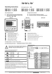
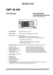
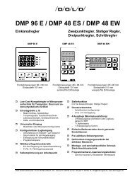
7.6.1 Monitoring the optimization process:<br />
The diagrams show possible incorrect settings with suggestions as to how to correct them.<br />
X<br />
(°C)<br />
W<br />
X<br />
(°C)<br />
W<br />
X<br />
(°C)<br />
W<br />
Pb too small<br />
Control oscillating<br />
Ti too small<br />
Td too large<br />
t<br />
t<br />
t<br />
X<br />
(°C)<br />
W<br />
X<br />
(°C)<br />
W<br />
X<br />
(°C)<br />
W<br />
Optimum setting<br />
Optimum setting<br />
Optimum setting<br />
Figure 4: Incorrect settings of the feedback parameters<br />
t<br />
t<br />
t<br />
X<br />
(°C)<br />
W<br />
X<br />
(°C)<br />
W<br />
X<br />
(°C)<br />
W<br />
Pb too large<br />
slow start-up<br />
and poor control<br />
Ti too large<br />
Td too small<br />
t<br />
t<br />
t<br />
22
DOLD <strong>GmbH</strong> <strong>Operating</strong> <strong>Instructions</strong> <strong>DMP</strong> <strong>96</strong> C<br />
8. Line Balancing, Zero Point Correction:<br />
Line balancing or zero point correction can be effected to the respective <strong>channel</strong> with the parameters<br />
" 1.Lin " to " 4.Lin " (<strong>channel</strong> 1 to <strong>channel</strong> 4).<br />
When the actual value is calculated, the offset value set is either added to, or subtracted from it.<br />
9. Error and Faults:<br />
9.1 List of possible error messages (display):<br />
Errordisplayed:<br />
Version: 115 Date: 08/2007 No. of pages: 25<br />
35E115B 07.doc<br />
Cause: Action /Description:<br />
1 Writing error I²C-bus Switch unit off/on<br />
2 Attempted division by zero Switch unit off/on<br />
3 Wrong low-pass filter entered Re-enter parameter " ti.Fi"<br />
(parameter " ti.Fi ")<br />
and switch unit off/on<br />
10 Sensor error <strong>channel</strong> 1 or<br />
sensor error <strong>channel</strong> 1 to 4 during<br />
self-tuning<br />
Check sensor<br />
11 Sensor error <strong>channel</strong> 2 Check sensor<br />
12 Sensor error <strong>channel</strong> 3 Check sensor<br />
13 Sensor error <strong>channel</strong> 4 Check sensor<br />
30 Reading error E²prom Switch unit off/on<br />
31 Device not calibrated Return unit for calibration<br />
32 Calibration faulty Return unit for calibration<br />
10. Program version:<br />
112 35<br />
actual software and program numbers:<br />
internal factory number<br />
actual software number<br />
• Version 010 22.12.93 basic version: multi <strong>channel</strong> PID controller<br />
• Version 020 08.03.94 added: limit contacts 1 to 5 (optional)<br />
• Version 021 09.05.94 added: configuration according to purchase order:<br />
heating or cooling PID controller, heating or<br />
cooling controller with adjustable switching<br />
hysteresis; for max. three analogue outputs.<br />
23
DOLD <strong>GmbH</strong> <strong>Operating</strong> <strong>Instructions</strong> <strong>DMP</strong> <strong>96</strong> C<br />
• Version 022 03.06.94 added: separate set points for <strong>channel</strong> 1 to 4,<br />
operation level changed.<br />
correction: 09.06.94: name of parameters "X.rdo" and<br />
"X.ruP" in the operation instructions.<br />
• Version 023 22.06.94 correction: two point controller with hysteresis setting:<br />
start up self-tuning disabled.<br />
• Version 024 05.08.94 new function: error acknowledgement by code 110;<br />
each relay can take off controller functions or<br />
limit values functions. The <strong>channel</strong> who refers<br />
the function, can be discontinued in the configu-<br />
ration level.<br />
Units with 2 and 3 <strong>channel</strong>s and free numbers<br />
of relay are disposable;<br />
units with analogue outputs current 4...20 mA<br />
are deliverable.<br />
• Version 025 05.08.94 correction: controlling of limit contacts 1 to 5.<br />
• Version 030 02.02.95 new function: insert a new interface routine for visual software,<br />
revision of the software program.<br />
• Version 031 09.02.95 new function: limit contacts with locking configurable.<br />
• Version 110 23.05.95 new function: Pt 100: <strong>channel</strong> 1 and <strong>channel</strong> 2 always three<br />
wire lead,<br />
controller character <strong>channel</strong> 1 to <strong>channel</strong> 4<br />
configurable,<br />
error-handling of the outputs changed,<br />
no total locking of the outputs in case of an input<br />
error.<br />
• Version 111 18.03.<strong>96</strong> correction: by switching on the unit in auto start - function<br />
the relays don't attract shortly.<br />
• Version 112 22.09.97 new function: start/stop - function by logic input 7,<br />
set point value setting by pressing the key for<br />
short time,<br />
parameter for lower range and upper range<br />
according to type of sensor,<br />
range of standard signal value configurable<br />
(0...20 mA / 4...20 mA or<br />
0...10 V DC / 2...10 V DC).<br />
• Version 113 18.05.98 new function: interface software expanded (parameter higher<br />
0x3ff now describable via interface).<br />
immunity added to operating manual.<br />
• Version 114 23.07.98 new function: additional parameters now accessible via<br />
interface,<br />
releasing function of the integrator changed.<br />
• Version 115 23.09.98 correction: evaluation of the logic inputs changed.<br />
• Version 115 21.08.07 change Company-Logo and-Address<br />
Version: 115 Date: 08/2007 No. of pages: 25<br />
35E115B 07.doc<br />
24
DOLD <strong>GmbH</strong> <strong>Operating</strong> <strong>Instructions</strong> <strong>DMP</strong> <strong>96</strong> C<br />
11. Immunity:<br />
The noise immunity of the controller has been tested using noise immunity test equipment of<br />
the Schaffner company (CH).<br />
• Type NSG 222A: interference simulator with fast interference pulses, a wide band<br />
interference spectrum, a very short rise time and little energy<br />
Version: 115 Date: 08/2007 No. of pages: 25<br />
35E115B 07.doc<br />
testdata: puls polarity: ± 2500 V<br />
rise time: 5 ns<br />
symmetrical and asymmetrical coupling<br />
• Type NSG 225A: burst simulator with a wide band interference spectrum and a very<br />
short rise time<br />
testdata: step 3: 2000 V<br />
frequency: 5 kHz<br />
• Type NSG 203A: test with mains line interruption<br />
testdata: 100% mains line interruption: 50 ms<br />
frequency: 1 Hz<br />
25