Universal Garage Door Remote Control - Home Alarm Systems ...
Universal Garage Door Remote Control - Home Alarm Systems ...
Universal Garage Door Remote Control - Home Alarm Systems ...

You also want an ePaper? Increase the reach of your titles
YUMPU automatically turns print PDFs into web optimized ePapers that Google loves.
<strong>Universal</strong> <strong>Garage</strong> <strong>Door</strong><br />
<strong>Remote</strong> <strong>Control</strong> Model G5V<br />
Thank you for your purchase of the Skylink garage door remote control,<br />
Model G5V. There are 3 different steps you need to set-up in order to use<br />
this universal garage door remote control to operate your existing garage<br />
door opener. These 3 steps are:<br />
1) Frequency switch – select the correct frequency according to the<br />
brand of your existing garage door opener.<br />
2) Brand jumpers – place the brand jumpers at the correct position<br />
according to the brand of your existing garage door opener.<br />
3) Code setting – Set the jumper connectors on the Model G5V so that<br />
they match the code setting of your existing garage door opener.<br />
In this package, you should find a garage door remote control with 12V<br />
alkaline battery and a clip.<br />
<strong>Garage</strong> <strong>Door</strong><br />
<strong>Remote</strong> <strong>Control</strong><br />
(Battery inside)<br />
Please follow the detailed instructions below in order to setup the<br />
Skylink Model G5V to work with your existing opener.<br />
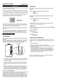
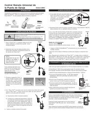
2. PROGRAMMING YOUR NEW TRANSMITTER<br />
1. SET FREQUENCY SWITCH<br />
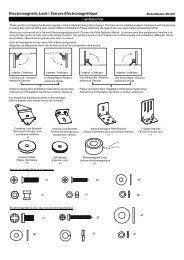
1a. Locate frequency switch on the top<br />
of the transmitter. (See diagram A)<br />
1b. Determine the brand of your garage<br />
door opener and set the frequency<br />
switch to the corresponding position.<br />
(See chart 1)<br />
Brand of your opener<br />
Chamberlain ®<br />
Lift-Master ®<br />
Sears ®<br />
Wayne Dalton ®<br />
Master Mechanic ®<br />
Genie ®<br />
Overhead ® 390MHz only<br />
Linear ®<br />
M-O-M ®<br />
Stanley ®<br />
Multi-Code ®<br />
Martec/Teckey ®<br />
Skylink ® UR-100<br />
Pulsar ® /Allstar ® /Allister ®<br />
Linear ® MegaCode TM<br />
Skylink ® 18 series<br />
2. SET BRAND JUMPER<br />
1. INTRODUCTION<br />
USA<br />
Set switch<br />
to position Frequency<br />
A or B<br />
A or B<br />
A or B<br />
D or A<br />
A<br />
A<br />
A<br />
C<br />
C<br />
C<br />
D or C<br />
D<br />
A<br />
Chart 1<br />
2a. To set the brand jumpers, open the<br />
case with a coin (see diagram B).<br />
390 or 315<br />
390 or 315<br />
390 or 315<br />
300 or 390<br />
390<br />
390<br />
390<br />
310<br />
310<br />
310<br />
300 or 310<br />
300<br />
390<br />
N/A<br />
N/A<br />
N/A<br />
Diagram A<br />
Diagram B<br />
A B C D<br />
CANADA<br />
Set switch<br />
to position Frequency<br />
C or A<br />
C or A<br />
C or A<br />
C or A<br />
C or A<br />
C or A<br />
A<br />
D<br />
D<br />
D<br />
D<br />
A<br />
B<br />
B<br />
B<br />
USA<br />
N/A<br />
A<br />
315 or 390<br />
315 or 390<br />
315 or 390<br />
315 or 390<br />
315 or 390<br />
315 or 390<br />
390<br />
310<br />
310<br />
310<br />
310<br />
390<br />
318<br />
318<br />
318<br />
B<br />
C<br />
D<br />
390 315 310 300<br />
CANADA 390 318 315 310<br />
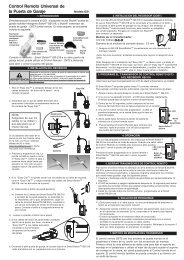
2b. The Model G5V contains 2 brand jumpers and 12 code connectors<br />
(see diagram C). The brand jumpers are located just above the<br />
battery with markings “A” and “B”. There are 2 connectors, one is<br />
placed on the “A” column, the other one is placed on the “B” column.<br />
For each column, there is a connector. If the connector is placed on<br />
the top and middle post of that column, that<br />
column is set on “+”. If the connector is<br />
placed on the middle and bottom posts, that<br />
column is set on “-“. If the connector is<br />
removed completely, that column is set on “0”<br />
(see diagram C). In order for the Model G5V to<br />
work with your existing garage door opener<br />
(motor), you need to set the brand jumpers<br />
based on the brand of your existing garage<br />
door opener. Please set these 2 brand jumpers<br />
“A” and “B” based on the brand jump ers setting<br />
on chart 2. Please identify the group number<br />
on chart 2 in order to determine which is the<br />
next step to proceed.<br />
Clip<br />
Code connector Location<br />
Brand<br />
Jumper<br />
BATTERY<br />
A = “+” B = “-”<br />
REMOVE JUMPER = “0”<br />
Diagram C<br />
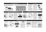
2. PROGRAMMING YOUR NEW TRANSMITTER (CONT)<br />
For garage door openers belonging to groups 1 to 5, please follow<br />
step 3 of the procedures, this will complete the setup. No need to proceed<br />
to step 4.<br />
For garage door openers belonging to groups 6 to 0, you can<br />
proceed directly to “Step 4 – Set Code Connector” after you have<br />
successfully set the brand jumpers. Please skip step 3 below.<br />
Group Brand Brand jumpers setting Proceed to<br />
1 Chamberlain ® , Sears ® , Lift-Master ®<br />
* Note:<br />
For Genie ® Intellicode TM & Overhead Code Dodger TM , if the brand<br />
jumper for group 3 cannot operate your garage door opener properly,<br />
please use setting A “-”, B “+”.<br />
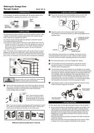
3. LEARN CODE<br />
Note:<br />
Proceed to this step only if the brand of your garage door opener<br />
belongs to either group 1, 2, 3, 4 or 5 on chart 2. Otherwise, proceed<br />
to Step 4 - Set code connector.<br />
3a. If your existing garage door opener belongs to any brand from group<br />
1, 2, 3, 4 or 5 then you should find a “learn” button from the garage door<br />
opener (the unit with the motor located on the ceiling of your garage,<br />
see diagram D). Press this learn button for approximately 2 seconds.<br />
The LED light beside the learn button will go on and then press the<br />
button on the Model G5V to activate it. The LED light on the garage<br />
door opener will flash then go off.<br />
The Model G5V is now programmed<br />
to your existing garage door opener<br />
and will operate your garage door.<br />
Programming is now completed<br />
and please refer to the “Battery”<br />
section of this manual for battery<br />
maintenance. Diagram D<br />
4. SET CODE CONNECTORS<br />
<strong>Garage</strong> <strong>Door</strong><br />
Opener (GDO)<br />
‘Learn’ Button<br />
Note:<br />
Proceed to this step only if the brand of your garage door opener<br />
belongs to either group 6, 7, 8, 9 or 0 on chart 2. Otherwise, proceed<br />
to Step 3 - Learn code.<br />
4a. If the brand of your garage door opener<br />
belongs to groups 6 to 0, that means you<br />
need to program the correct code setting<br />
in order for the Model G5V to work with<br />
your existing garage door opener. There<br />
are 12 code connectors on 12 columns<br />
from 1 to 12 (see diagram E). Each column<br />
has one connector. (see diagram F)<br />
A B<br />
(without DIP switches but with red, orange or purple + -<br />
learn button)<br />
2 Chamberlain ® , Lift-Master ® , Sears ® , Wayne Dalton ® , - 0<br />
Master Mechanic ® (without DIP switches but with<br />
yellow, white, gray or green learn button)<br />
3* Genie ® Intellicode TM * (without DIP switches) + +<br />
Overhead Code Dodger TM * (without DIP switches)<br />
4 Linear ® MegaCode TM (Canada only) 0 -<br />
5 Skylink ® 18 series (Canada only) 0 0<br />
6 Genie ® (with DIP switches), Overhead ®<br />
+ 0<br />
7 Chamberlain ® , Lift-Master ® , Sears ® , Wayne Dalton ® , - +<br />
Master Mechanic ® (with DIP switches)<br />
8 Stanley ® , Multi-Code ® , Martec ®<br />
9 Linear ® , Moore-O-Matic ®<br />
- -<br />
0 +<br />
0 Pulsar ® / Allstar ® / Allister ® (Canada only) 0 -<br />
Chart 2<br />
Proceed<br />
to Step 3.<br />
Proceed<br />
to Step 4,<br />
skip Step 3.<br />
Diagram E<br />
Diagram F<br />
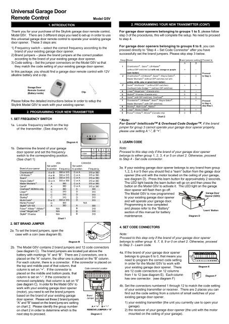
4b. Set the connectors numbered 1 through 12 to match the code setting<br />
of your existing transmitter or receiver. There are 2 places you can<br />
find out the code setting from a column of small switches of your<br />
existing garage door opener.<br />
1) your existing transmitter (the unit you currently use to open your<br />
garage).<br />
2) the receiver of your garage door opener (the unit with the motor<br />
mounted on the ceiling of your garage).
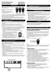
2. PROGRAMMING YOUR NEW TRANSMITTER (CONT)<br />
4c. If the connector is placed on the top and<br />
middle posts, that column is set on “ + ”<br />
or “ON” or “CLOSE”. If the connector is<br />
placed on the middle and bottom posts,<br />
that column is set on “ - ” or “OFF” or<br />
“OPEN”. If the connector is removed completely,<br />
(not placed on any posts), it is set<br />
to “ 0 ” or the neutral position. (see<br />
diagram G for examples of how to set a<br />
column to the three different positions).<br />
When removing a connector to set a<br />
column to the neutral position, save the<br />
connector in case you change the code<br />
at a later date.<br />
4d. To move the connectors, slide an opened<br />
paper clip into the side of a connector and<br />
lift. (see diagram H) When repositioning<br />
connectors, place a connector on the two<br />
chosen posts, then push down on the<br />
connector with your finger.<br />
Diagram H<br />
Set the connectors numbered 1 through 12 to match the switches of<br />
your existing transmitter or receiver. If your garage door opener is<br />
manufactured by (Stanley ®, Genie ® , Multi-Code ® , Linear ® , Moore-O-<br />
Matic ® ) these switches may only have two positions, ( “ + , ON, CLOSED”<br />
and “ - , OFF, OPEN”). (see diagram I) Set the connectors on the model<br />
G5V to “ + ” if your existing switches are either “ +, ON, CLOSE ” and<br />
set to “ - ” if your existing switches are either “ -, OFF, OPEN”. Do not<br />
use the blank position “0”.<br />
Existing<br />
Transmitter<br />
Code connector setting to match your opener/motor<br />
Examples of how to set Model G5V<br />
Diagram I<br />
If your existing transmitter has fewer than 12<br />
switches, match only the first corresponding<br />
connectors. Leave the remaining posts blank<br />
(remove the connectors). Press the button on<br />
the transmitter.<br />
If the garage door does not open, reverse all<br />
of the connectors on the model G5V. The “ + ”<br />
will be changed to the “ - ” position and the “ -<br />
” position will be changed to the “ + ” position.<br />
(see diagram J)<br />
Model G5V<br />
‘-’ or ‘OFF’ or ‘OPEN’<br />
‘+’ or ‘ON’ or CLOSE ‘0’ = BLANK<br />
Diagram G<br />
Linear Position 1 to 8 + OR -<br />
M-O-M Position 1 to 8 + OR -<br />
Stanley (310) Canada Position 1 to 10 + OR - 11,12 set to ‘+’ or ‘-’<br />
Stanley (300) Position 1 to 10 + OR - 11,12 set to ‘+’ or ‘-’<br />
Multi-Code Position 1 to 10 + OR - 11,12 set to ‘+’ or ‘-’<br />
Chamberlain Position 1 to 9 +, 0 (blank), OR -<br />
Lift-Master Position 1 to 9 +, 0 (blank), OR -<br />
Sears Position 1 to 9 +, 0 (blank), OR -<br />
Wayne Dalton Position 1 to 9 +, 0 (blank), OR -<br />
Master Mechanic Position 1 to 9 +, 0 (blank), OR -<br />
Genie (9 positions) Position 1 to 9 + OR -<br />
Genie (12 positions) Position 1 to 12 + OR -<br />
Overhead Position 1 to 9 +, 0 (blank), OR -<br />
Martec/Teckey Position 1 to 10 + OR - 11,12 set to ‘+’<br />
Pulsar/Allister/Allstar Position 1 to 9 +, 0 (blank), OR -<br />
Original Position<br />
Reversed Position<br />
Diagram J<br />
If your garage door opener is manufactured by (Chamb erlain ® ,Sears ® , Lift-<br />
Master ®, Wayne Dalton ® or Master Mechanic ®) the switches will have 3<br />
positions, (“ + , 0, - ”). Set the connectors on the model G5V to match their<br />
corresponding positions. If your opener is a Sears ®, Chamberlain ® or Lift-<br />
Master ® and the existing transmitter has three buttons, (see diagram K), the<br />
first connector in the model #G5V may need to be changed to another<br />
position. If your Chamberlain ® ,Sears ® , Lift-Master ® has 9 DIP switches,<br />
match them to the first 9 connectors on the model G5V and remove the<br />
last 3 connectors (connectors 10, 11, 12). If there are only 8 DIP switches<br />
on your Chamberlain ® ,Sears ® , Lift-Master ®, match them to the 2-9 position<br />
on the model G5V and remove the last 3 connectors (connectors 10, 11, 12).<br />
2. PROGRAMMING YOUR NEW TRANSMITTER (CONT)<br />
Now you may have to change the positioning<br />
of the #1 connector on the model G5V. If the large<br />
button of Diagram K is used to open the garage<br />
door, set the #1 connector to “ - ” position. If the<br />
middle button is used, set the #1 connector to the<br />
“ 0 ” or “blank” position. If the smaller button on the<br />
left is used, s et the #1 connector to the “ + ” position.<br />
3. OPERATION<br />
5. WARNING<br />
Diagram K<br />
To operate the model G5V with your GDO properly, please press the<br />
button on the model G5V.<br />
NOTE:<br />
Transmission range may be reduced with use on a metal garage door.<br />
12 volt alkaline battery (size 23A)<br />
included.<br />
4. BATTERY<br />
If this transmitter triggers other garage doors in your neighborhood, change all your<br />
transmitters and receiver to a new code setting.<br />
DO NOT let children use the garage door transmitter without adult supervision.<br />
Children can injure themselves or others by the garage door.<br />
6. FCC<br />
The <strong>Universal</strong> <strong>Garage</strong> <strong>Door</strong> <strong>Remote</strong> <strong>Control</strong> is approved by the FCC and it complies<br />
with Part 15 of the FCC Rules. Its operation is subject to the f ollowing two conditions :<br />
1. This device may not cause harmful interference.<br />
2. This device must accept any interference that may cause undesired operation.<br />
WARNING:<br />
Changes or modifications to this unit not expressly approved by the party<br />
responsible of compliance could void the user’s authority to operate the equipment.<br />
7. WARRANTY<br />
If, within one year from date of purchase, this product should become defective<br />
(except battery), due to faulty workmanship or materials, it will be repaired or<br />
replaced, without charge. Proof of purchase and a Return Authorization are required.<br />
8. CUSTOMER SERVICE<br />
If your Skylink <strong>Universal</strong> <strong>Remote</strong> <strong>Control</strong> does not activate your <strong>Garage</strong> <strong>Door</strong><br />
Opener, the reason may be that your GDO age or manufacturer is not listed on the<br />
compatibility chart.<br />
The solution is the Skylink SG-18R <strong>Universal</strong> Receiver.<br />
If you would like to order Skylink’s product or have difficulty getting your Skylink’s<br />
remote control to work, please :<br />
1. visit our FAQ section at www.skylinkhome.com , or<br />
2. email us at support@skylinkhome.com, or<br />
3. call our toll free at 1-800-304-1187 from Monday to Friday, 9 am to 5 pm EST.<br />
Fax (800) 286-1320<br />
CUSTOMER SERVICE<br />
17 Sheard Avenue, Brampton, Ontario, Canada L6Y 1J3<br />
Email:support@skylinkhome.com<br />
http://www.skylinkhome.com<br />
P/N. 101A398-001<br />
US Patent. D377458, 5680134, 5841390, 6005508, 6956460<br />
Patent Pending<br />
® are registered trademarks of their respective corporations<br />
©2005 SKYLINK GROUP