Front mounted light curtains (if applicable) - Albany Door Systems
Front mounted light curtains (if applicable) - Albany Door Systems
Front mounted light curtains (if applicable) - Albany Door Systems

You also want an ePaper? Increase the reach of your titles
YUMPU automatically turns print PDFs into web optimized ePapers that Google loves.
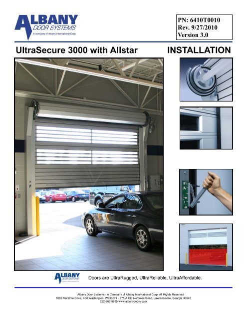
<strong>Door</strong>s are UltraRugged, UltraReliable, UltraAffordable.<br />
<strong>Albany</strong> <strong>Door</strong> <strong>Systems</strong> - A Company of <strong>Albany</strong> International Corp. All Rights Reserved<br />
1080 Maritime Drive, Port Washington, WI 53074 - 975-A Old Norcross Road, Lawrenceville, Georgia 30046<br />
262-268-9885 www.albanydoors.com<br />
PN: 6410T0010<br />
Rev. 9/27/2010<br />
Version 3.0<br />
UltraSecure 3000 with Allstar INSTALLATION
STATEMENT OF WARRANTY<br />
UltraSecure 3000 High Speed <strong>Door</strong>s<br />
ONE-YEAR WARRANTY ON MECHANICAL AND ELECTRICAL COMPONENTS<br />
<strong>Albany</strong> <strong>Door</strong> <strong>Systems</strong> warrants to the original owner of the door that the mechanical and electrical components will be<br />
free from defects in material and workmanship for a period of one (1) year from the date of shipment. The warranty does<br />
not cover fuses, heat lamp elements, bulbs, and seals.<br />
Only defects brought to the attention of <strong>Albany</strong> <strong>Door</strong> <strong>Systems</strong> during the warranty period will be covered by this warranty.<br />
<strong>Albany</strong> <strong>Door</strong> <strong>Systems</strong> will replace component parts covered by this warranty, which are found to be defective upon inspection<br />
by an <strong>Albany</strong> <strong>Door</strong> <strong>Systems</strong> representative. Installation or use of parts other than those authorized by <strong>Albany</strong><br />
<strong>Door</strong> <strong>Systems</strong> will void this warranty.<br />
PARTS AND ASSEMBLIES sold separately by <strong>Albany</strong> <strong>Door</strong> <strong>Systems</strong> that fail due to defects in material or workmanship<br />
within ninety (90) days from the date of shipment will be replaced under warranty provided installation has been carried<br />
out in accordance with all <strong>Albany</strong> <strong>Door</strong> <strong>Systems</strong> procedures. This warranty is limited to providing a replacement part only.<br />
This warranty does not cover freight, special charges, or any costs associated with the installation of the replacement part.<br />
This warranty covers material failure under normal wear conditions; it does not cover damage caused by collision or other<br />
abuse of the product. Adjustments made to the control panel or to the mechanical operation of the door without the authorization<br />
of <strong>Albany</strong> <strong>Door</strong> <strong>Systems</strong> will void this warranty. Any changes made to product configuration without the express<br />
written approval from <strong>Albany</strong> <strong>Door</strong> <strong>Systems</strong> may null and void this warranty.<br />
<strong>Albany</strong> <strong>Door</strong> <strong>Systems</strong>’ obligations under this warranty are limited to repairing or replacing the defective part including<br />
labor and <strong>Albany</strong> <strong>Door</strong> <strong>Systems</strong> shall not be responsible for any other losses or damages due to the operation of any<br />
door or parts covered by this warranty. Warranty parts will be shipped regular ground freight at the expense of <strong>Albany</strong><br />
<strong>Door</strong> <strong>Systems</strong>.<br />
This warranty shall be void in its entirety <strong>if</strong> the failure of any product shall be caused by any installation, operation, or maintenance<br />
of the product which does not conform with the requirements set forth by the seller in the <strong>applicable</strong> product<br />
manuals or is in the result of any cause other than a defect in the material or workmanship of the product.<br />
No other oral or written representations made by <strong>Albany</strong> <strong>Door</strong> <strong>Systems</strong> or its agents are a part of this warranty unless<br />
spec<strong>if</strong>ically set forth in writing by an authorized <strong>Albany</strong> <strong>Door</strong> <strong>Systems</strong> official.<br />
THE ABOVE SET FORTH WARRANTY IS SELLER'S SOLE WARRANTY. SELLER MAKES NO OTHER WARRANTY<br />
OF ANY KIND WHATSOEVER, EXPRESSED OR IMPLIED; AND ALL IMPLIED WARRANTIES OF MERCHANTABIL-<br />
ITY AND FITNESS FOR A PARTICULAR PURPOSE WHICH EXCEED THE AFORESTATED OBLIGATION ARE<br />
HEREBY DISCLAIMED BY SELLER AND EXCLUDED FROM THIS AGREEMENT.<br />
WARNING<br />
Do not install, operate or service the product unless you have read and understand<br />
the safety practices, warnings, installation and maintenance instructions contained<br />
In this manual.<br />
<strong>Albany</strong> <strong>Door</strong> <strong>Systems</strong> - A Company of <strong>Albany</strong> International Corp. All Rights Reserved<br />
1080 Maritime Drive, Port Washington, WI 53074 - 975-A Old Norcross Road, Lawrenceville, Georgia 30045<br />
262-268-9885 or 877-9252468<br />
v4202010<br />
Rev. 9/27/2010 Manual # 6410T0010 Page 2
INTRODUCTION<br />
The contents of this manual are designed to help you install UltraSecure 3000 high speed doors.<br />
DO NOT begin to install the high speed door unless you have read through the instructions in<br />
this manual.<br />
The safety alert symbol is used to ident<strong>if</strong>y safety information about hazards that can<br />
result in personal injury. A signal word (DANGER, WARNING, or CAUTION) is used<br />
with the safety alert symbol to indicate the likelihood and the potential severity of injury.<br />
In addition, a hazard symbol may be used to represent the type of hazard.<br />
Other symbols that may be used in this manual are:<br />
DANGER indicates a hazard that, <strong>if</strong> not avoided, will<br />
result in death or serious injury.<br />
WARNING indicates a hazard that, <strong>if</strong> not avoided,<br />
could result in death or serious injury.<br />
CAUTION indicates a hazard that, <strong>if</strong> not avoided,<br />
might result in minor or moderate injury.<br />
CAUTION, when used without the alert symbol, indicates<br />
a situation that could result in damage to the<br />
door.<br />
NOTICE is used to inform you of a method, reference,<br />
or procedure that could assist with spec<strong>if</strong>ic<br />
operations or procedures.<br />
Lock Out / Tag Out Crushing Fire Shock Read Manual<br />
Rev. 9/27/2010 Manual # 6410T0010 Page 3
WALL ANCHORING GUIDE<br />
<strong>Albany</strong> <strong>Door</strong> <strong>Systems</strong> does not supply hardware for mounting the door to the wall. Use proper hardware best<br />
suited for each particular door installation. Some examples are shown below. It is the responsibility of the<br />
door owner to ensure that the wall material is strong enough to support the forces of the door and all anchoring<br />
hardware. In general, <strong>Albany</strong> <strong>Door</strong> <strong>Systems</strong> recommends through-bolting wherever possible using ½ inch<br />
diameter bolts/threaded-rods or 1/2 inch diameter concrete expansion anchors.<br />
Rev. 9/27/2010 Manual # 6410T0010 Page 4
INSTALLATION REFERENCE MARKS – 3000R<br />
Measure from the inside of the left door jamb to the inside of the right door jamb and place a<br />
mark on the floor on the door opening centerline.<br />
Reference the door’s documentation and place a mark on the floor at <strong>Door</strong> Width<br />
2<br />
Rev. 9/27/2010 Manual # 6410T0010 Page 5
INSTALLATION REFERENCE MARKS – 3000STD<br />
Measure from the inside of the left door jamb to the inside of the right door jamb and place a<br />
mark on the floor on the door opening centerline.<br />
Reference the door’s documentation and place a mark on the floor at <strong>Door</strong> Width<br />
2<br />
Rev. 9/27/2010 Manual # 6410T0010 Page 6
INSTALLATION REFERENCE MARKS – 3000XL<br />
Measure from the inside of the left door jamb to the inside of the right door jamb and place a<br />
mark on the floor on the door opening centerline.<br />
Reference the door’s documentation and place a mark on the floor at <strong>Door</strong> Width<br />
2<br />
Rev. 9/27/2010 Manual # 6410T0010 Page 7
Delivery and Inspection<br />
Improper installation of anchoring devices or installation<br />
into aged or unsound concrete block, or other<br />
wall material may result in premature wear, product<br />
failure, property damage, or serious personal injury.<br />
Lock-Out Tag-out all electrical power supplied to<br />
the door before making any electrical installations<br />
or connections. Also Lock-out Tag-out any equipment<br />
near the installation site <strong>if</strong> that equipment may<br />
be inadvertently operated into the area used to assemble<br />
and install the door. Failure to properly<br />
deenergize electrical circuits and disable equipment<br />
during installation and/or maintenance could result<br />
in death or serious injury.<br />
Use proper l<strong>if</strong>ting equipment and techniques. Properly<br />
secure all loads. Failure to properly secure all<br />
l<strong>if</strong>ting loads could result in death or serious injury.<br />
Secure the work area so that persons<br />
not working directly on the installation<br />
do not enter the work area.<br />
SITE PREPARATION<br />
Electrical Supply<br />
Qual<strong>if</strong>ied electrician must make all electrical<br />
mountings and connections in accordance with<br />
all <strong>applicable</strong> regulating body(s) electrical codes<br />
and standards. The control box is equipped with<br />
primary voltage fusing.<br />
<strong>Door</strong> Opening<br />
1.Are the door jambs and support wall structurally<br />
sound providing a flat surface for the side<br />
columns to mount against?<br />
2.Check the width and height of the door opening<br />
and ver<strong>if</strong>y the measurements against the dimensions<br />
of the door.<br />
3.Is the opening square? Plumb?<br />
4.Is the floor level across the opening?<br />
Make all necessary structural repairs and improvements<br />
to provide a “yes” answer to each of the questions above.<br />
TOOLS AND MATERIALS REQUIRED<br />
Personnel<br />
Two people to install the door<br />
One person qual<strong>if</strong>ied to operate forkl<strong>if</strong>t, hoist,<br />
or crane<br />
Once electrician to install and connect the control<br />
panel and all electrical wiring<br />
Tools<br />
Assorted wrenches<br />
Tape measure<br />
Carpenter’s square<br />
Level (4ft minimum recommended)<br />
L<strong>if</strong>ting device (fork l<strong>if</strong>t, hoist, crane)<br />
L<strong>if</strong>ting Straps<br />
2 ladders or personnel l<strong>if</strong>ts (tall enough to reach<br />
above the door head)<br />
Other tools as needed for the type of anchoring<br />
chosen<br />
Materials<br />
Anchors appropriate for the type of wall the door<br />
and accessories are to be installed onto. <strong>Albany</strong><br />
<strong>Door</strong> <strong>Systems</strong> recommends throughbolting<br />
doors whenever possible.<br />
Wire as spec<strong>if</strong>ied on the electrical schematic<br />
Electrical supplies needed to comply with all<br />
regulating body electrical codes and standards.<br />
UNPACKING AND PREPARING<br />
1.Inspect and unpack the components. Report any damage<br />
immediately to <strong>Albany</strong> <strong>Door</strong> <strong>Systems</strong> at 262-268-<br />
9885. Refer to the serial number tag located on the<br />
door side frame.<br />
2.DO NOT cut the banding which holds the door in a roll<br />
until instructed to do so in a later procedure.<br />
The door panel and roll assembly could be<br />
damaged. Use evenly spaced padded supports<br />
to prevent rips, tears, or bending of<br />
the roll assembly. Failure to protect the roll<br />
assembly could result in damage to the<br />
door.<br />
Rev. 9/27/2010 Manual # 6410T0010 Page 8
PREPARATION FOR DOOR ASSEMBLY<br />
Prior to door installation, the door opening must be examined to insure the existing wall<br />
construction is sufficient to support the door. For all UltraSecure <strong>Door</strong> versions, the side<br />
frames should be supported by a steel structure or concrete wall. If the door opening is<br />
insufficient to support the door a steel column or equivalent construction must be installed prior to the door installation.<br />
Do not install the doors on insulated panel walls, honeycomb bricks or <strong>light</strong>weight partition walls.<br />
The door opening width and height must be checked to ensure that the door received is the same size as the opening.<br />
This can be achieved by comparing the manufactured door size listed in the corresponding door paperwork to the actual<br />
door measurements.<br />
The door opening must be closed to all vehicle or pedestrian traffic during the installation process.<br />
Prior to the installation the stretch wrap and/or shrink film needs to be removed from the shipping pallets. After this has<br />
occurred remove the springs and other loose door components from the inside of the side frames and place to the side.<br />
until required for installation.<br />
MOUNTING AND DISMOUNTING<br />
All UltraSecure <strong>Door</strong>s<br />
The top roll shipping pallet has two basic functions. The 1 st . is as a shipping pallet or support & the 2 nd is as an installation<br />
aid. Use of the fork guides is required to insure that the door does not tip or slide.<br />
The complete side frames assemblies are located on/in a separate shipping pallet.<br />
The Control box, drive unit and other materials for installation are located in a cardboard box, which is located in one of<br />
the shipping pallets.<br />
Rev. 9/27/2010 Manual # 6410T0010 Page 9
SIDE FRAME AND WIDTH GAUGE<br />
If the door opening declines or slopes from side to side 1 st attach the side frame that is located on<br />
the highest side. Both side frames must be placed at the same elevation.<br />
Attach the side frame within the upper mounting slots provided to the wall with at least four<br />
½” (12mm) or equivalent bolts or screws.<br />
Mounting Holes<br />
Attach the lower portion of the side frame using either the mounting slots in the back of the side<br />
frame or the holes located in the base plate. At least two bolts or screws required at this location.<br />
Rev. 9/27/2010 Manual # 6410T0010 Page 10
Place the second side frame on the wall and attach loosely once the width has been ver<strong>if</strong>ied.<br />
Using the same procedures as the first side frame attach the upper portion using the provided<br />
slots. Leave attachment screws loose until all side frame adjustments are made.<br />
Assemble lintel sealing profile before installing<br />
on the door. Use metal connector to join the<br />
profiles. Metal connector has a slotted hole<br />
used for wall anchoring. This bracket must be<br />
anchored.<br />
Double check door width by measuring<br />
between side frame black plastic wear<br />
strips.<br />
DO NOT USE THE LINTEL SEALING<br />
PROFILE TO SET THE WIDTH OF<br />
THE DOOR.<br />
Before attaching the lower portion of the side frame ver<strong>if</strong>y the door opening by measuring the<br />
distance between the black plastic wear guides. This measurement should be the same as the<br />
manufactured door size. After checking the measurement ver<strong>if</strong>y that the door is plumb in all<br />
directions.<br />
Attach the lower section using the same procedure as the first side frame.<br />
Rev. 9/27/2010 Manual # 6410T0010 Page 11
Side Frame Alignment for Light Curtains<br />
Run a mason’s line through the predrilled hole in the side frame to the same hole in the other frame.<br />
Next, measure the distance from the back of the frame to the mason’s line. Repeat this for the near<br />
and far side of the frame. The frame is properly aligned when the value for both measurements is<br />
the same. If the measurements are not the same, shim the rear of the frame on the side with the<br />
higher measured value. Repeat for both frames.<br />
Install <strong>light</strong> curtain using the pre-drilled holes. Space the <strong>light</strong> curtain off the frame using the<br />
supplied 3 fender washers with the mounting screws.<br />
The <strong>light</strong> curtain must be set so that the bottom of the <strong>light</strong> curtain is 2” off the floor.<br />
Be careful not to over tighten the screws as they can pull through the aluminium track of the <strong>light</strong><br />
curtain.<br />
Tighten the width gauge screws.<br />
The width gauge serves as a cable duct for the stationary photocells and <strong>light</strong> curtain wires.<br />
Rev. 9/27/2010 Manual # 6410T0010 Page 12
TOP ROLL<br />
DO NOT REMOVE THE PACKING STRAPS FROM THE TOP ROLL<br />
First loosen the three screws attaching the bearing flange to the bearing plate on both sides of the<br />
barrel. This will allow for easier positioning of the roll into the side frame cradle cut out.<br />
L<strong>if</strong>t the top roll onto the side frames using a forkl<strong>if</strong>t, crane or other equivalent device. Position the top<br />
roll so that the center of the bearing flange is centered over the cradle cut out. Lower the roll so that<br />
the flange rests on the cradle. The two piece bearing flange sandwiches the side frame.<br />
3000R ONLY. The drive unit must be installed on<br />
the top roll shaft prior to installing the top roll.<br />
Align the point of the mounting plate with the existing hole in the side frame.<br />
The picture at the left shows the standard<br />
and XL frame while the picture above shows<br />
the R frame.<br />
Rev. 9/27/2010 Manual # 6410T0010 Page 13
By hand, start all three of the M10 barrel fastening screws into the bearing plate. Next, tighten the bearing flange screws<br />
loosened earlier. Tighten the remaining 3 barrel fastening screws. Repeat the process on the other side.<br />
Once both sides are secure, the header l<strong>if</strong>ting cradle can be cut away.<br />
When cutting away the cradle, be careful not to cut the barrel securing straps.<br />
These straps will keep the barrel wound until the gear motor assembly is installed.<br />
Cutting these straps will result in the barrel free falling.<br />
The barrel may begin to turn when the cradle is removed. However, the plastic straps will prevent the panel from unwinding<br />
and falling.<br />
If FULL ROLL COVERS were purchased, mount the motor-side full roll cover<br />
plate. Refer to the full roll cover assembly section for details. Failure to follow<br />
this step will result in lost time removing and re-installing the gear motor.<br />
Attach the mounting plate to the side frame with the provided M10 screws. Next tighten the three bearing flange bolts.<br />
Repeat this step for both sides of the door.<br />
GEARMOTOR<br />
This section applies only to the standard and XL version of the UltraSecure.<br />
Slide the drive unit onto the shaft of the top roll. Align the motor hollow shaft to the top roll shaft with the use of a 6mm<br />
hex key driven from below the fan guard.<br />
Connect the torque arm to the drive and side frame as shown.<br />
Rotate the barrel to align the bottom slat to<br />
the side frame funnel by pulling down on the<br />
brake release handle and rotating the barrel<br />
by hand. Release the brake. You are now<br />
ready to cut the barrel straps.<br />
Rev. 9/27/2010 Manual # 6410T0010 Page 14
This section applies only to the R version.<br />
Release the brake to allow the motor torque arm to swing to position over the motor attachment<br />
bracket. Screw the attachment bolt through the vibration dampener until it bottoms out.<br />
From underneath the motor attachment bracket, use the nut and lock washer to complete the motor<br />
bracket assembly.<br />
Rev. 9/27/2010 Manual # 6410T0010 Page 15
COUNTERBALANCE<br />
This section applies only to the standard and XL version.<br />
Attach the counterbalance belts to the barrel under the metal bracket. Pre-wrap 2 turns of the belt in<br />
the opposite direction that the curtain will roll up.<br />
Run the counterbalancing belts behind the idler pullies and down the side frames. Please note that<br />
the belt must run flat against the pulley & free of any twisting.<br />
Rev. 9/27/2010 Manual # 6410T0010 Page 16
COUNTERBALANCE<br />
This section applies only to the R version.<br />
Attach the counterbalance belts to the barrel under the metal bracket. Pre-wrap 2 turns of the belt in<br />
the opposite direction that the curtain will roll up. Secure the belt by tightening the clamp plate<br />
screws.<br />
Adjust the belt guide so that with the door open,<br />
the funnel edge is just off of the belt.<br />
Rev. 9/27/2010 Manual # 6410T0010 Page 17
Run the counterbalance belts through the upper spring attachment bracket.<br />
With the door in the open position add the appropriate pre stretch to the spring length and set the upper spring<br />
bracket at this location.<br />
DH 2000mm (78.75”) � 6” of pre-stretch<br />
Hang the springs in the upper spring attachment brackets then stretch the springs down and attach to the<br />
lower brackets.<br />
Rev. 9/27/2010 Manual # 6410T0010 Page 18
This section applies to doors equipped with an electric<br />
reversing edge .<br />
The electric edge connection<br />
is made utilizing a cable chain<br />
assembly <strong>mounted</strong> in the drive<br />
side cabinet. The cable chain<br />
has an 8M plug on the end<br />
that will attach to a mating plug<br />
that is installed on the bottom<br />
slat end bracket as show to<br />
the left and right.<br />
Before cycling the door you<br />
must ver<strong>if</strong>y that the cable<br />
chain assembly does NOT<br />
make contact with the side<br />
frame base plate as shown in<br />
detail A below. You should<br />
have a clearance of 3/8” - 3/4”<br />
from the floor.<br />
Contact with the base plate<br />
can cause permanent damage<br />
to the cable chain assembly.<br />
Rev. 9/27/2010 Manual # 6410T0010 Page 19
Bottom L<strong>if</strong>t Strap Assembly<br />
Attach the l<strong>if</strong>t belt to Adapter 4 by wrapping the l<strong>if</strong>t belt under the adapter and passing the M5 x 20<br />
screw through the front and back holes of the belt. The washer is placed on the front and the<br />
threaded belt clamp is positioned behind. Use the fender washers provided. Repeat for both sides.<br />
Rev. 9/27/2010 Manual # 6410T0010 Page 20
Top position proximity switch<br />
The position of the top position<br />
proximity switch (1) is adjustable by<br />
loosening screw (2) and sliding the<br />
prox thru the slotted hole to obtain a<br />
gap of 3mm or 1/16” between the<br />
prox and the #4 adapter target<br />
plate. The target plate is shown<br />
pulled back away form the prox for<br />
clarity.<br />
NOTE: The standard 3000 and XL<br />
models have a prox orientation of<br />
vertical as shown to the right and<br />
the 3000R has a horizontal orientation<br />
as shown below.<br />
Either orientation requires adjustment.<br />
Rev. 9/27/2010 Manual # 6410T0010 Page 21
BRAKE RELEASE CABLE ROUTING<br />
Create a loop with 1 of 2 cable<br />
clamps supplied and hook the<br />
loop to the brake release handle<br />
spring.<br />
Once the slack of the inner cable<br />
is pulled thru you will now<br />
thread on the outer sheath making<br />
sure to include the ferrules<br />
on both ends of the sheath.<br />
On the R model thread the inner<br />
cable thru the small hole in the<br />
belt guide plate and pull all the<br />
slack thru.<br />
Now thread the inner cable down<br />
thru the brake release rod and pull<br />
the inner cable all the way thru<br />
until the outer sheath buts up to<br />
the brake release rod.<br />
On the Std and XL models the<br />
inner cable will thread thru the<br />
top support plate as shown and<br />
pull all the slack thru.<br />
Now loop the cable thru the grid<br />
on the fan shroud and pull all the<br />
slack thru. Tighten the cable<br />
clamp to retain the cable at this<br />
point.<br />
Proper operation of the brake release will allow for the outer sheath to push down on the brake release rod of the motor.<br />
S<strong>light</strong> tension adjustments of the cable may be required. Once adjusted, cut the cable excess leaving 4 or more inches.<br />
Use caution when pulling the brake release so as not to allow the door curtain<br />
to travel out of the top of the guides.<br />
Rev. 9/27/2010 Manual # 6410T0010 Page 22
SIDE FRAME COVERS<br />
Install the cover gussets using the appropriate slots located<br />
in the side frame (Standard and XL configuration only).<br />
Attach the outer covers using<br />
the appropriate slots located<br />
in the side frame and the provided<br />
hardware. It may be<br />
necessary to push the cover<br />
toward the door blade to start<br />
the screws. Use care not to<br />
cross thread the compression<br />
nut inserts.<br />
It is critical to have a smooth<br />
transition between the upper<br />
and lower plastic rails.<br />
The gap between the plastic rails & the curtain should be approximately 0.04” (1mm).<br />
The R model<br />
does not have<br />
an inner cover<br />
gusset as<br />
above. It only<br />
has a one<br />
piece outer<br />
cover. The<br />
bolting flange<br />
of the cover<br />
has slotted<br />
holes to allow<br />
for cover adjustment.<br />
There is also a<br />
reinforcement<br />
gusset at the<br />
top of the<br />
cover that will<br />
need to be<br />
bolted in place as well. Use care not to<br />
cross thread the compression nut inserts.<br />
High impact tools are not recommended for<br />
installing these bolts.<br />
The XL model has an additional outer cover that has<br />
slotted holes in the bolting flange which allows for<br />
the gap adjustment to be made as shown below.<br />
Rev. 9/27/2010 Manual # 6410T0010 Page 23
Install the side frame spring box covers with the provided hardware.<br />
<strong>Front</strong> <strong>mounted</strong> <strong>light</strong> <strong>curtains</strong> (<strong>if</strong> <strong>applicable</strong>)<br />
Mount <strong>light</strong> <strong>curtains</strong> to the<br />
bracket on the side frame using<br />
two M4 screws supplied with<br />
the <strong>light</strong> <strong>curtains</strong>. Plug the <strong>light</strong><br />
curtain cable into the supplied<br />
M12 cable.<br />
Rev. 9/27/2010 Manual # 6410T0010 Page 24
FULL ROLL AND MOTOR COVERS<br />
These instructions pertain to the Standard and XL versions only.<br />
Install the side cover (1) assembly before mounting the drive unit. After the remaining installation is<br />
completed install the front cover (3) and the top cover (4) with the provided hardware.<br />
Rev. 9/27/2010 Manual # 6410T0010 Page 25
Using the hardware provided install the motor cover back to the side plate (1). Next install the bottom<br />
cover (2), then the front cover (3), and finish by installing the top cover (4).<br />
These instructions below pertain to the 3000R version only.<br />
Install the support plates of the top roll cover at the side frames. Next attach the front cover followed<br />
by the top cover.<br />
Electrical Installation Manual:<br />
Allstar-w-Encoder-3000-Install-Manual 6401T0011<br />
Install the motor cover.<br />
Rev. 9/27/2010 Manual # 6410T0010 Page 26
Installation Checklist<br />
Please fill out below and return to <strong>Albany</strong> <strong>Door</strong> <strong>Systems</strong><br />
Customer Installation Date(s):<br />
Location: <strong>Door</strong> Serial #(s):<br />
Contact: Contact Phone #:<br />
Install Company: Contact & Phone #:<br />
Mechanical Installation (All <strong>Door</strong>s) Yes No<br />
Is the door secured to the wall using thru-bolts?<br />
If No, what type of anchor was used?<br />
Are the door roll and rear spreader level?<br />
Are the side columns plumb?<br />
Does the door have counterweights?<br />
If Yes, are the straps routed properly?<br />
Is the door caulked or sealed to the wall?<br />
Are there any visible gaps between the door and the<br />
wall?<br />
If No, did the customer contact approve of door to<br />
wall seal?<br />
Is there any visible damage to the door?<br />
If Yes, what is the damage?<br />
Was Customer Service not<strong>if</strong>ied of the damage?<br />
Rev. Was 9/27/2010 the customer contact not<strong>if</strong>ied Manual of the damage?<br />
# 6410T0010 Page 27
Electrical Installation Yes No<br />
Were the factory supplied cables (motor, encoder & 7wire)<br />
long enough?<br />
If No, which cables were too short?<br />
If No, was Customer Support contacted and new<br />
cables sent?<br />
Were the schematics easy to read for electrical hookup?<br />
What type of conduit was used to route the cables to<br />
the door?<br />
Is the conduit routed to the bottom of the control box?<br />
If No, did the customer approve this?<br />
If No, why?<br />
If Yes, who was the customer contact that approved?<br />
Rev. 9/27/2010 Manual # 6410T0010 Page 28
<strong>Door</strong> Start-Up Yes No<br />
Was the door start-up procedure easy to follow?<br />
If No, what problem(s) did you run into?<br />
Was Customer Support not<strong>if</strong>ied of these issues?<br />
Is the Reversing Edge working?<br />
Are the front and rear <strong>light</strong> <strong>curtains</strong> (or photo-eyes)<br />
working?<br />
Do the bottom bar breakaway switches work? N/A<br />
Does the door’s self-repair feature work when the door<br />
is broken away? N/A<br />
If the door has counterweights, does the egress work?<br />
Rev. 9/27/2010 Manual # 6410T0010 Page 29
Activation Yes No<br />
What type of activation is being used?<br />
Was the activation supplied by <strong>Albany</strong> <strong>Door</strong> <strong>Systems</strong>?<br />
Did the customer approve of the mounting and operation<br />
of the activators?<br />
Comments<br />
Please email digital pictures of the installed door to: support@albint.com<br />
Rev. 9/27/2010 Manual # 6410T0010 Page 30
Inspection Plan<br />
Observe the safety notices within the operation manual. Power to the door must be shut off prior to<br />
inspection of any door component.<br />
Before Installation checking fixings the following mentioned components the cover in front of the<br />
spring housing and eventually the existing top roll and motor cover must be<br />
dismantled.<br />
Drive unit<br />
Annually or 100,000 cycles.<br />
Check retainer of the torque support and buffer. Annually or 100,000 cycles.<br />
Check function of brake release lever. Annually or 100,000 cycles.<br />
Check self-opening/manual opening/egress<br />
Drive shaft<br />
Annually or 100,000 cycles.<br />
Check flange bearing retainers of drive shaft. Annually or 100,000 cycles.<br />
Check retainer of the spiral disk on the shaft. Annually or 100,000 cycles.<br />
Check condition of sound isolation or black dampener profiles on the spiral disks. Annually or 100,000 cycles.<br />
Exchange of flat l<strong>if</strong>ting belts.<br />
<strong>Door</strong> leaf<br />
500,000 cycles.<br />
Check surface of lamellas/slats for grinding and signs of damages. Annually or 100,000 cycles.<br />
Check exact position of lamella sealing. Annually or 100,000 cycles.<br />
Check fixing of lamellas on pulling device. Annually or 100,000 cycles.<br />
Check solid position of lamella adapter/endplates.<br />
Guiding rails<br />
Annually or 100,000 cycles.<br />
Check for wear and tear on guidingrails, especially in the area of funnel (
<strong>Albany</strong> <strong>Door</strong> <strong>Systems</strong> - A Company of <strong>Albany</strong> International Corp. All Rights Reserved<br />
1080 Maritime Drive, Port Washington, WI 53074 - 975-A Old Norcross Road, Lawrenceville, Georgia 30046<br />
262-268-9885 www.albanydoors.com<br />
Rev. 9/27/2010 Manual # 6410T0010 Page 32