

DSD/DSDQ Shear Load Connectors - Geo-Hidrol
DSD/DSDQ Shear Load Connectors - Geo-Hidrol
DSD/DSDQ Shear Load Connectors - Geo-Hidrol

Create successful ePaper yourself
Turn your PDF publications into a flip-book with our unique Google optimized e-Paper software.
CI/SfB<br />
Jh3<br />
March 2006<br />
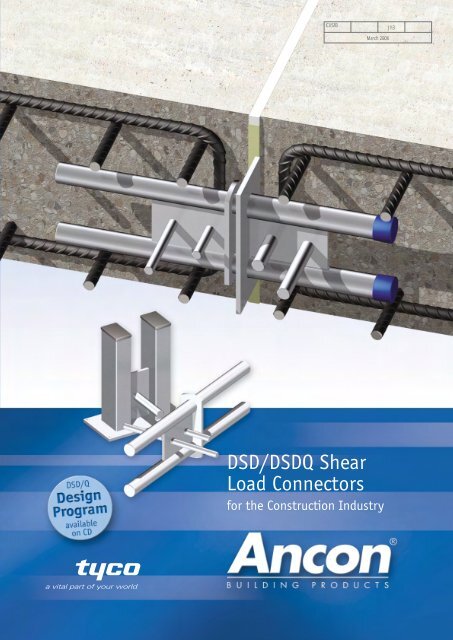
<strong>DSD</strong>/<strong>DSD</strong>Q <strong>Shear</strong><br />
<strong>Load</strong> <strong>Connectors</strong><br />
for the Construction Industry
Ancon designs and manufactures high integrity steel products for<br />
the construction industry. Through continuous programmes of<br />
new product development, inward investment and employee<br />
advancement, the company is committed to maintaining the<br />
highest level of customer service within a dynamic and<br />
challenging industry.<br />
Masonry Support Systems<br />
Windposts and Lintels<br />
Wall Ties and Restraint Fixings<br />
Channel and Bolt Fixings<br />
Tension Systems<br />
Special Fabrications<br />
Flooring & Formed Sections<br />
<strong>Shear</strong> <strong>Load</strong> <strong>Connectors</strong><br />
Reinforcing Bar Couplers<br />
Reinforcement Continuity Systems<br />
Punching <strong>Shear</strong> Reinforcement<br />
Insulated Balcony <strong>Connectors</strong><br />
Refractory Fixings<br />
Reinforced concrete is an important<br />
construction material. It offers strength,<br />
durability and can be formed into a variety of<br />
shapes. Concrete structures are designed with<br />
expansion and contraction joints at appropriate<br />
places to allow movement to take place. The<br />
design of the joint is important for the overall<br />
design to function correctly.<br />
Ancon shear load connectors offer significant<br />
advantages over conventional single dowels.<br />
Ancon Solution to Joints 4<br />
Ancon <strong>DSD</strong>/Q <strong>Shear</strong> <strong>Connectors</strong> 5<br />
Performance Details 6-7<br />
Dimensions and Spacings 8<br />
Reinforcement Details 9-10<br />
Material Properties 10<br />
Applications 11<br />
Other Ancon Products 11<br />
BS EN ISO 9001 : 2000<br />
FM12226<br />
3
4<br />
<strong>Shear</strong> <strong>Load</strong> <strong>Connectors</strong><br />
ANCON SOLUTION TO JOINTS<br />
In most cases conventional dowelled or<br />
corbelled joints can be replaced by joints<br />
incorporating Ancon shear connectors. These<br />
are more effective at transferring load and<br />
allowing movement to take place, easier to fix<br />
on site and a far more cost effective solution.<br />
They can be used for movement joints in floor<br />
slabs, suspended slabs, and for replacing<br />
double columns and beams at structural<br />
movement joints. Applications in civil<br />
engineering include joints in bridge parapets,<br />
bridge abutments and diaphragm wall<br />
construction.<br />
Comparison of Performance with<br />
Conventional Single Dowels<br />
Grade C30<br />
Concrete & Six 32mm<br />
Joint Width One Ancon Dia Dowel<br />
of 20mm <strong>DSD</strong>130 Bars<br />
Dowel<br />
Diameter mm<br />
2 @ 35 32<br />
Area of<br />
2 Dowel mm<br />
1924 4825<br />
Serviceability<br />
<strong>Load</strong> kN<br />
145 138<br />
1 Ancon <strong>DSD</strong> 130 Serviceability<br />
<strong>Load</strong> 145kN<br />
6 Dowel Bars 32mm Diameter<br />
Serviceability <strong>Load</strong> 138kN<br />
Conventional Joints<br />
Slip Joint<br />
Slab Corbel<br />
Structural Movement Joint<br />
Ancon Solutions<br />
Ancon <strong>DSD</strong><br />
Double Columns Ancon <strong>DSD</strong><br />
Floor to Wall Connection<br />
Corbel Support Ancon <strong>DSD</strong>
Tel: +44 (0) 114 275 5224 Web: www.ancon.co.uk<br />
ANCON SHEAR LOAD CONNECTORS<br />
The <strong>DSD</strong> range of connectors offers significant<br />
advantages over conventional single dowels.<br />
Each connector is a two-part assembly<br />
comprising a sleeve and a dowel component.<br />
Installation is a fast and accurate process,<br />
drilling of either formwork or concrete is not<br />
required. The sleeve is simply nailed to the<br />
formwork ensuring subsequent alignment with<br />
the dowel, essential for effective movement.<br />
They are manufactured from stainless steel to<br />
ensure a high degree of corrosion resistance<br />
with no requirement for additional protection.<br />
Free software is available from Ancon that<br />
simplifies the design of movement joints in<br />
reinforced concrete. For a given application,<br />
Ancon’s design program will calculate the size<br />
and quantity of shear load connectors<br />
required, the edge distance and spacings at<br />
which they should be installed, and details of<br />
the local reinforcement.<br />
Ancon <strong>DSD</strong> <strong>Shear</strong> <strong>Connectors</strong><br />
The Ancon <strong>DSD</strong> is the original two-part,<br />
double dowel, shear load connector. The<br />
dowel component can move longitudinally<br />
within the sleeve to accommodate movement.<br />
The connector is available in ten standard<br />
sizes and can transfer loads from around 20kN<br />
to over 450kN. The larger connectors can be<br />
used in joints up to 60mm wide. Larger joints<br />
can be accommodated using special dowels.<br />
Please contact Ancon’s Technical Department<br />
for further information.<br />
Ancon <strong>DSD</strong>Q <strong>Shear</strong> <strong>Connectors</strong><br />
The Ancon <strong>DSD</strong>Q shear load connector<br />
uses the same dowel component as the<br />
Ancon <strong>DSD</strong>, but the cylindrical sleeve is<br />
contained within a rectangular box section to<br />
allow lateral movement in addition to the<br />
longitudinal movement. Nine standard sizes<br />
can be used to transfer loads from around<br />
30kN to over 450kN.<br />
Dowel bar<br />
Web plate<br />
Ancon <strong>DSD</strong>Q <strong>Shear</strong> <strong>Connectors</strong> allowing<br />
rotation<br />
Plan<br />
Lateral movement<br />
or rotation<br />
Guide tube<br />
Longitudinal<br />
movement<br />
Longitudinal<br />
movement<br />
End plate with<br />
nail holes<br />
Cross dowels<br />
End cap<br />
<strong>DSD</strong><br />
Sleeve within<br />
rectangular<br />
box section<br />
<strong>DSD</strong>Q<br />
Ancon <strong>DSD</strong>Q <strong>Shear</strong> <strong>Connectors</strong> allowing<br />
movement in two directions<br />
Ancon <strong>DSD</strong>Q<br />
<strong>Shear</strong> <strong>Connectors</strong><br />
Slab movement will be<br />
in opposite directions in<br />
this area<br />
5
6<br />
<strong>Shear</strong> <strong>Load</strong> <strong>Connectors</strong><br />
Ultimate Failure <strong>Load</strong>s (kN) for Various Design Joint Widths (mm) and Slab Thickness (mm)*<br />
Slab <strong>DSD</strong>/<strong>DSD</strong>Q Ref 0 10 20 30 40 50 60<br />
160 61.2 52.0 46.0 39.9 31.0 - -<br />
180 66.5 56.5 50.0 39.9 31.0 - -<br />
200<br />
220<br />
25**<br />
72.2<br />
78.5<br />
61.4<br />
66.7<br />
54.3<br />
55.0<br />
39.9<br />
39.9<br />
31.0<br />
31.0<br />
-<br />
-<br />
-<br />
-<br />
240 81.6 69.3 55.0 39.9 31.0 - -<br />
260 81.6 69.3 55.0 39.9 31.0 - -<br />
180 94.0 87.0 78.8 58.3 45.6 - -<br />
200 101.2 93.6 78.8 58.3 45.6 - -<br />
220<br />
240<br />
30<br />
108.9<br />
117.3<br />
100.8<br />
108.6<br />
78.8<br />
78.8<br />
58.3<br />
58.3<br />
45.6<br />
45.6<br />
-<br />
-<br />
-<br />
-<br />
260 125.3 111.2 78.8 58.3 45.6 - -<br />
280 125.3 111.2 78.8 58.3 45.6 - -<br />
180 112.3 104.2 97.3 81.0 64.0 52.5 -<br />
200 120.8 112.2 104.7 81.0 64.0 52.5 -<br />
220<br />
240<br />
50<br />
130.1<br />
140.1<br />
120.8<br />
130.1<br />
107.5<br />
107.5<br />
81.0<br />
81.0<br />
64.0<br />
64.0<br />
52.5<br />
52.5<br />
-<br />
-<br />
260 149.6 139.0 107.5 81.0 64.0 52.5 -<br />
280 149.6 139.0 107.5 81.0 64.0 52.5 -<br />
200 147.5 138.4 130.3 108.4 86.4 71.2 -<br />
220 157.6 147.9 139.2 108.4 86.4 71.2 -<br />
240<br />
260<br />
65<br />
168.5<br />
180.1<br />
158.0<br />
168.9<br />
141.2<br />
141.2<br />
108.4<br />
108.4<br />
86.4<br />
86.4<br />
71.2<br />
71.2<br />
-<br />
-<br />
280 192.4 180.5 141.2 108.4 86.4 71.2 -<br />
300 196.6 184.4 141.2 108.4 86.4 71.2 -<br />
240 179.7 169.6 160.5 140.5 113.0 93.7 -<br />
260 190.0 179.2 169.6 140.5 113.0 93.7 -<br />
280<br />
300<br />
75<br />
200.8<br />
212.3<br />
189.4<br />
200.2<br />
179.3<br />
179.7<br />
140.5<br />
140.5<br />
113.0<br />
113.0<br />
93.7<br />
93.7<br />
-<br />
-<br />
320 224.4 211.6 179.7 140.5 113.0 93.7 -<br />
340 237.1 223.7 179.7 140.5 113.0 93.7 -<br />
320 303.8 289.9 277.2 235.7 199.4 170.7 148.2<br />
340 316.6 302.1 278.4 235.7 199.4 170.7 148.2<br />
360<br />
380<br />
100<br />
330.1<br />
336.7<br />
314.9<br />
318.8<br />
278.4<br />
278.4<br />
235.7<br />
235.7<br />
199.4<br />
199.4<br />
170.7<br />
170.7<br />
148.2<br />
148.2<br />
400 336.7 318.8 278.4 235.7 199.4 170.7 148.2<br />
420 336.7 318.8 278.4 235.7 199.4 170.7 148.2<br />
360 380.9 364.4 349.2 335.3 298.3 259.3 227.5<br />
380 395.2 378.0 362.3 345.0 298.3 259.3 227.5<br />
400<br />
420<br />
130<br />
410.0<br />
425.5<br />
392.2<br />
407.0<br />
375.9<br />
390.1<br />
345.0<br />
345.0<br />
298.3<br />
298.3<br />
259.3<br />
259.3<br />
227.5<br />
227.5<br />
440 441.5 422.4 395.9 345.0 298.3 259.3 227.5<br />
460 458.2 438.3 395.9 345.0 298.3 259.3 227.5<br />
450 505.7 488.0 469.8 452.8 430.3 381.3 339.4<br />
500 544.2 525.2 505.6 484.8 430.3 381.3 339.4<br />
550<br />
600<br />
150<br />
586.0<br />
599.7<br />
565.5<br />
583.0<br />
539.6<br />
539.6<br />
484.8<br />
484.8<br />
430.3<br />
430.3<br />
381.3<br />
381.3<br />
339.4<br />
339.4<br />
650 599.7 583.0 539.6 484.8 430.3 381.3 339.4<br />
700 599.7 583.0 539.6 484.8 430.3 381.3 339.4<br />
600 643.7 631.7 599.2 554.8 506.4 459.5 416.7<br />
650 643.7 631.7 599.2 554.8 506.4 459.5 416.7<br />
700<br />
750<br />
400<br />
643.7<br />
643.7<br />
631.7<br />
631.7<br />
599.2<br />
599.2<br />
554.8<br />
554.8<br />
506.4<br />
506.4<br />
459.5<br />
459.5<br />
416.7<br />
416.7<br />
800 643.7 631.7 599.2 554.8 506.4 459.5 416.7<br />
850 643.7 631.7 599.2 554.8 506.4 459.5 416.7<br />
650 1005.8 993.6 959.6 910.0 851.8 791.2 732.2<br />
700 1005.8 993.6 959.6 910.0 851.8 791.2 732.2<br />
750 1005.8 993.6 959.6 910.0 851.8 791.2 732.2<br />
800<br />
850<br />
450<br />
1005.8<br />
1005.8<br />
993.6<br />
993.6<br />
959.6<br />
959.6<br />
910.0<br />
910.0<br />
851.8<br />
851.8<br />
791.2<br />
791.2<br />
732.2<br />
732.2<br />
900 1005.8 993.6 959.6 910.0 851.8 791.2 732.2<br />
950 1005.8 993.6 959.6 910.0 851.8 791.2 732.2<br />
* In C25/30 concrete as defined in EN206-1 : 2000<br />
** <strong>DSD</strong> only<br />
1<br />
2<br />
3<br />
4<br />
5<br />
6<br />
Installation<br />
Direction<br />
of load
Tel: +44 (0) 114 275 5224 Web: www.ancon.co.uk<br />
Serviceability <strong>Load</strong>s (kN) for Various Design Joint Widths (mm) and Slab Thickness (mm)*<br />
Slab <strong>DSD</strong>/<strong>DSD</strong>Q Ref 0 10 20 30 40 50 60<br />
160 25.5 21.7 19.2 17.5 16.8 - -<br />
180 27.7 23.5 20.8 19.0 16.8 - -<br />
200<br />
220<br />
25**<br />
30.1<br />
32.7<br />
25.6<br />
27.8<br />
22.6<br />
24.6<br />
20.7<br />
21.7<br />
16.8<br />
16.8<br />
-<br />
-<br />
-<br />
-<br />
240 34.0 28.9 25.5 21.7 16.8 - -<br />
260 34.0 28.9 25.5 21.7 16.8 - -<br />
180 39.2 36.3 33.7 31.6 24.8 - -<br />
200 42.2 39.0 36.3 31.7 24.8 - -<br />
220<br />
240<br />
30<br />
45.4<br />
48.9<br />
42.0<br />
45.2<br />
39.1<br />
42.1<br />
31.7<br />
31.7<br />
24.8<br />
24.8<br />
-<br />
-<br />
-<br />
-<br />
260 52.2 48.3 42.8 31.7 24.8 - -<br />
280 52.2 48.3 42.8 31.7 24.8 - -<br />
180 46.8 43.4 40.5 38.0 34.8 28.5 -<br />
200 50.3 46.7 43.6 40.9 34.8 28.5 -<br />
220<br />
240<br />
50<br />
54.2<br />
58.4<br />
50.3<br />
54.2<br />
47.0<br />
50.6<br />
44.0<br />
44.0<br />
34.8<br />
34.8<br />
28.5<br />
28.5<br />
-<br />
-<br />
260 62.4 57.9 54.0 44.0 34.8 28.5 -<br />
280 62.4 57.9 54.0 44.0 34.8 28.5 -<br />
200 61.4 57.6 54.3 51.3 46.9 38.7 -<br />
220 65.7 61.6 58.0 54.8 46.9 38.7 -<br />
240<br />
260<br />
65<br />
70.2<br />
75.0<br />
65.9<br />
70.4<br />
62.0<br />
66.3<br />
58.6<br />
58.9<br />
46.9<br />
46.9<br />
38.7<br />
38.7<br />
-<br />
-<br />
280 80.2 75.2 70.8 58.9 46.9 38.7 -<br />
300 81.9 76.8 72.4 58.9 46.9 38.7 -<br />
240 74.9 70.6 66.9 63.5 60.4 50.9 -<br />
260 79.1 74.7 70.7 67.1 61.4 50.9 -<br />
280<br />
300<br />
75<br />
83.7<br />
88.4<br />
78.9<br />
83.4<br />
74.7<br />
79.0<br />
70.9<br />
74.9<br />
61.4<br />
61.4<br />
50.9<br />
50.9<br />
-<br />
-<br />
320 93.5 88.2 83.5 76.3 61.4 50.9 -<br />
340 98.8 93.2 88.2 76.3 61.4 50.9 -<br />
320 126.6 120.8 115.5 110.6 106.2 92.8 80.5<br />
340 131.9 125.9 120.4 115.3 108.4 92.8 80.5<br />
360<br />
380<br />
100<br />
137.5<br />
143.4<br />
131.2<br />
136.8<br />
125.5<br />
130.8<br />
120.2<br />
125.3<br />
108.4<br />
108.4<br />
92.8<br />
92.8<br />
80.5<br />
80.5<br />
400 149.5 142.6 136.4 128.1 108.4 92.8 80.5<br />
420 155.8 148.7 142.2 128.1 108.4 92.8 80.5<br />
360 158.7 151.8 145.5 139.7 134.3 129.4 123.6<br />
380 164.7 157.5 151.0 144.9 139.4 134.2 123.6<br />
400<br />
420<br />
130<br />
170.8<br />
177.3<br />
163.4<br />
169.6<br />
156.6<br />
162.5<br />
150.4<br />
156.0<br />
144.6<br />
150.1<br />
139.3<br />
140.9<br />
123.6<br />
123.6<br />
440 184.0 176.0 168.7 161.9 155.7 140.9 123.6<br />
460 190.9 182.6 175.0 168.0 161.6 140.9 123.6<br />
450 210.7 203.3 195.7 188.7 182.1 176.0 170.3<br />
500 226.8 218.8 210.7 203.1 196.0 189.4 183.2<br />
550<br />
600<br />
150<br />
244.2<br />
262.9<br />
235.6<br />
253.7<br />
226.8<br />
244.3<br />
218.6<br />
235.4<br />
211.0<br />
227.3<br />
203.9<br />
207.2<br />
184.5<br />
184.5<br />
650 280.9 271.0 260.9 251.5 233.8 207.2 184.5<br />
700 280.9 271.0 260.9 251.5 233.8 207.2 184.5<br />
600 319.0 308.8 299.2 290.1 275.2 249.7 226.5<br />
650 337.0 326.2 316.1 301.5 275.2 249.7 226.5<br />
700<br />
750<br />
400<br />
349.8<br />
349.8<br />
343.3<br />
343.3<br />
325.7<br />
325.7<br />
301.5<br />
301.5<br />
275.2<br />
275.2<br />
249.7<br />
249.7<br />
226.5<br />
226.5<br />
800 349.8 343.3 325.7 301.5 275.2 249.7 226.5<br />
850 349.8 343.3 325.7 301.5 275.2 249.7 226.5<br />
650 453.4 440.2 427.9 416.2 405.1 394.6 384.6<br />
700 477.0 463.2 450.2 437.9 426.2 415.2 397.9<br />
750 502.0 487.5 473.8 460.9 448.6 430.0 397.9<br />
800<br />
850<br />
450<br />
528.4<br />
546.6<br />
513.1<br />
540.0<br />
498.7<br />
521.5<br />
485.1<br />
494.5<br />
462.9<br />
462.9<br />
430.0<br />
430.0<br />
397.9<br />
397.9<br />
900 546.6 540.0 521.5 494.5 462.9 430.0 397.9<br />
950 546.6 540.0 521.5 494.5 462.9 430.0 397.9<br />
* In C25/30 concrete as defined in EN206-1 : 2000<br />
** <strong>DSD</strong> only<br />
7
8<br />
<strong>Shear</strong> <strong>Load</strong> <strong>Connectors</strong><br />
DIMENSIONS<br />
Dowel Component <strong>DSD</strong> Sleeve <strong>DSD</strong>Q Sleeve<br />
Dowel bar<br />
diameter<br />
Dowel length<br />
Anchor bar<br />
lengths<br />
Anchor bar<br />
position<br />
Projection<br />
Ref<br />
Dowel Component <strong>DSD</strong> Sleeve <strong>DSD</strong>Q Sleeve<br />
<strong>DSD</strong> Overall Dowel Dowel Dowel Anchor Bar Anchor Bar Overall Anchor Bar Anchor Bar Overall Anchor Bar Anchor Bar Lateral<br />
<strong>DSD</strong>Q Length Dia Centres Projection Position Lengths Length Position Lengths Length Position Length Mov’nt<br />
25* 250 14 40 120 31 80/140 120 28 80/140 - - - -<br />
30 260 16 48 120 31 80/140 120 28 80/140 140 33 100 26<br />
50 280 18 50 130 31 80/160 135 28 80/160 160 33 100 25<br />
65 300 20 65 150 31 80/160 155 29 80/160 175 33 150 21<br />
75 340 22 75 150 33 100/180 155 31 100/180 175 33 150 20<br />
100 400 30 100 210 34 100/200 210 36 100/200 235 54 200 41<br />
130 470 35 105 260 34 100/200 265 36 100/200 275 59 200 36<br />
150 550 42 120 270 54 100/240 275 41 100/240 305 54 210 21<br />
400 660 52 160 330 70 150/300 335 70 150/300 350 64 350 27<br />
450 690 65 180 360 80 180/350 370 80 180/350 400 89 350 54<br />
SPACINGS, SLAB & BEAM THICKNESSES<br />
Ancon <strong>DSD</strong> and <strong>DSD</strong>Q connectors should be<br />
positioned in slabs and beams within the<br />
minimum dimensions shown in the table below<br />
to ensure full load transfer. For information on<br />
reduced spacings or edge distances please<br />
contact Ancon.<br />
For slabs or beams with a thickness greater<br />
than the standard, the values for standard<br />
thickness apply. For slabs and beams with a<br />
thickness between the minimum and standard,<br />
use the formula shown.<br />
Ancon <strong>DSD</strong> and <strong>DSD</strong>Q Spacings and Minimum Concrete Thicknesses<br />
Ref<br />
Minimum Thickness Standard Thickness<br />
<strong>DSD</strong> Minimum Slab/ Minimum Minimum End Standard Slab/ Minimum Minimum End<br />
<strong>DSD</strong>Q Beam Thickness Centres Distance Beam Thickness Centres Distance<br />
25* 160 240 120 240 160 80<br />
30 180 270 135 270 180 90<br />
50 180 270 135 270 180 90<br />
65 200 300 150 300 200 100<br />
75 240 360 180 360 240 120<br />
100 320 480 240 480 320 160<br />
130 360 540 270 540 360 180<br />
150 450 675 337 675 450 225<br />
400 600 900 450 900 600 300<br />
450 650 975 487 975 650 325<br />
Minimum Centres =<br />
(2.5 x Min. Slab/Beam Thickness) – Actual Thickness<br />
End Distance = 0.5 x Minimum Centres<br />
Centres<br />
Notes:* <strong>DSD</strong> only. All dimensions are in millimetres (mm).<br />
Notes:* <strong>DSD</strong> only. All dimensions are in millimetres (mm).<br />
End<br />
distance Centres<br />
Anchor bar<br />
position<br />
Sleeve length<br />
Anchor bar<br />
lengths<br />
Example: Ancon <strong>DSD</strong>100 used in 350mm thick slab<br />
Minimum Centres = (2.5 x 320) - 350 = 450mm<br />
End Distance = 0.5 x 450 = 225mm<br />
=<br />
=<br />
Slab<br />
thickness<br />
Anchor bar<br />
position<br />
Sleeve length<br />
Anchor bar<br />
length<br />
Maximum<br />
lateral<br />
movement<br />
Beam thickness<br />
= =<br />
End<br />
distance<br />
Centres
Tel: +44 (0) 114 275 5224 Web: www.ancon.co.uk<br />
REINFORCEMENT<br />
Local Reinforcement<br />
Local reinforcement is required around each<br />
<strong>DSD</strong> dowel and sleeve component to bridge<br />
any fine cracks that develop in the concrete as<br />
the dowels transfer load. Correct detailing in<br />
accordance with BS 8110 and the<br />
recommendations provided here, will ensure<br />
the Ancon <strong>DSD</strong> and <strong>DSD</strong>Q shear connectors<br />
attain their full capacity.<br />
Slab Reinforcement<br />
Joint<br />
width<br />
Serviceability load<br />
Cover<br />
Bar diameter<br />
Vertical Reinforcement<br />
Cross Sectional Area (CSA) is calculated as<br />
CSA =<br />
2.4 x Serviceability <strong>Load</strong> x (Joint Width + Slab Thickness) x 103 follows:-<br />
0.87 x fy x (Slab Thickness - (2 x Cover) - Bar Diameter)<br />
Example <strong>DSD</strong>100 used in 400mm thick slab<br />
Actual serviceability load = 100kN Joint width = 20mm<br />
Bar diameter = 16mm fy = 500N/mm 2 Cover = 40mm<br />
CSA = = 762mm2 2.4 x 100 x (20 + 400) x 103<br />
0.87 x 500 x (400 - 80 - 16)<br />
Use 4 - H16 U-Bars (actual area - 804mm 2 )<br />
Top and Bottom Reinforcement<br />
CSA =<br />
Area of Vertical Reinforcement<br />
π<br />
From the example above<br />
CSA =<br />
762<br />
π<br />
= 243mm 2<br />
Use 6 - H8 (actual area - 301mm 2 )<br />
=<br />
=<br />
Slab<br />
Thickness<br />
100 100 100<br />
Typical Layout<br />
100<br />
(130 for<br />
<strong>DSD</strong> 400<br />
and above)<br />
Typical Layout<br />
Other U-bars<br />
top and bottom<br />
reinforcement<br />
not shown.<br />
Reinforcement Arrangement 1<br />
Ancon <strong>DSD</strong>25 - <strong>DSD</strong>150<br />
100<br />
100<br />
Reinforcement Arrangement 2<br />
Ancon <strong>DSD</strong>130 - <strong>DSD</strong>450<br />
9
10<br />
<strong>Shear</strong> <strong>Load</strong> <strong>Connectors</strong><br />
Beam Reinforcement<br />
The main consideration for beams is usually<br />
the design reinforcement to carry the shear<br />
load. This is provided in accordance with well<br />
established procedures set out in international<br />
codes, and will require shear links local to the<br />
Ancon <strong>DSD</strong> units.<br />
In addition to this reinforcement, particularly in<br />
thin beams, reinforcement must be added to<br />
prevent vertical splitting of the concrete. The<br />
reinforcement should be located as shown in<br />
the diagrams below.<br />
Cross Sectional<br />
Area of Local =<br />
Reinforcement<br />
Cross Sectional<br />
Area of Local =<br />
Reinforcement<br />
2.4 x Serviceability <strong>Load</strong> x 10 3<br />
π x 0.87 x fy<br />
Example: Ancon <strong>DSD</strong>100 in 350mm wide beam<br />
Actual serviceability load = 100kN<br />
fy of reinforcement = 500N/mm 2<br />
2.4 x 100 x 10 3<br />
π x 0.87 x 500<br />
Use 2 - H12 U-Bars (actual area - 226mm 2 )<br />
A<br />
A<br />
Width<br />
= =<br />
Section A-A<br />
= 176mm 2<br />
For further details of beam reinforcement, or<br />
for specific applications, please contact Ancon<br />
Building Products.<br />
75mm max<br />
Typical shape<br />
38 bar<br />
Typical shape<br />
60 bar<br />
Normal<br />
reinforcement<br />
Direction<br />
of load<br />
Typical<br />
shape<br />
38 bar<br />
Typical<br />
shape<br />
60 bar<br />
Normal<br />
reinforcement<br />
Wall Reinforcement<br />
Reinforcement in walls is designed in the<br />
conventional way as though the slab was<br />
integral with the wall. The additional local<br />
reinforcement is in the form of a square mesh<br />
or loose bar equivalent to the details as shown<br />
below.<br />
Minimum Width<br />
and Depth<br />
Ref Bar Maximum Minimum<br />
<strong>DSD</strong> Diameter Centres Width/Depth<br />
<strong>DSD</strong>Q (mm) (mm) (mm)<br />
25* 8 100 300<br />
30 8 100 300<br />
50 8 100 300<br />
65 10 100 400<br />
75 12 150 450<br />
100 12 150 450<br />
130 12 150 600<br />
150 12 175 700<br />
* <strong>DSD</strong> only<br />
Reinforcement for <strong>DSD</strong> 75s in a Wall<br />
H12 at 150mm<br />
max.centres<br />
450mm min.<br />
Wall Reinforcement<br />
Local Reinforcement<br />
to Connector<br />
<strong>DSD</strong>75<br />
Sleeve<br />
component<br />
450<br />
mm<br />
min.<br />
Cover<br />
Minimum cover to local reinforcement is to the<br />
recommendations of BS 8110 Part 1 : 1997.<br />
Maximum cover is as shown below:-<br />
Ref<br />
<strong>DSD</strong> Max Cover<br />
<strong>DSD</strong>Q to Face (mm)<br />
25* 30<br />
30 30<br />
50 30<br />
65 40<br />
75 50<br />
100 50<br />
130 50<br />
150 50<br />
400 60<br />
450 60<br />
* <strong>DSD</strong> only<br />
Cover<br />
Where a sleeve component<br />
is cast into a wall the<br />
thickness of the wall should<br />
be at least 50mm more than<br />
the length of the sleeve.<br />
50mm min.<br />
MATERIAL PROPERTIES<br />
Material Specification of Ancon <strong>DSD</strong><br />
<strong>Shear</strong> <strong>Connectors</strong><br />
Component Specification<br />
Dowel bar 1.4462<br />
Plate 1.4301<br />
Cross dowels 1.4301<br />
Material Strengths of Ancon <strong>DSD</strong>/Q<br />
Dowel Bars<br />
Ref 0.2% Tensile Elongation<br />
<strong>DSD</strong> Proof Stress Strength at Rupture<br />
<strong>DSD</strong>Q N/mm2 (Rp) N/mm2 (Rm) % (A10) 25* 780 850 15<br />
30 780 850 15<br />
50 780 850 15<br />
65 780 850 15<br />
75 780 850 15<br />
100 550 700 20<br />
130 550 700 20<br />
150 500 650 20<br />
400 350 650 25<br />
450 350 650 25<br />
* <strong>DSD</strong> only
Tel: +44 (0) 114 275 5224 Web: www.ancon.co.uk<br />
APPLICATIONS<br />
Channel Tunnel Terminal, UK<br />
Forum Shopping Centre, Algarve<br />
Melbourne Cricket Ground, Australia<br />
Scottish Widows, Edinburgh, UK<br />
Olympic Stadium, Sydney, Australia<br />
OTHER ANCON PRODUCTS<br />
Reinforcement Continuity Systems<br />
Reinforcement Continuity Systems are an<br />
increasingly popular means of maintaining<br />
continuity of reinforcement at construction<br />
joints in concrete. The system eliminates the<br />
need to drill shuttering and can simplify<br />
formwork design, thereby accelerating the<br />
construction process. The Ancon Eazistrip is<br />
available in both standard units and special<br />
configurations.<br />
Reinforcing Bar Couplers<br />
The use of reinforcing bar couplers can<br />
provide significant advantages over lapped<br />
joints. Design and construction of the concrete<br />
can be simplified and the amount of<br />
reinforcement required can be reduced.<br />
Because the strength of a mechanical splice is<br />
independent of the concrete in which it is<br />
located, the joint can also remain unaffected<br />
by any loss of cover. The range includes<br />
threaded and mechanically bolted couplers.<br />
Punching <strong>Shear</strong> Reinforcement<br />
Used within a slab to provide additional<br />
reinforcement around columns, Ancon <strong>Shear</strong>fix<br />
is the ideal solution to the design and<br />
construction problems associated with<br />
punching shear. The system consists of<br />
double-headed studs welded to flat rails,<br />
positioned in a symmetrical pattern around the<br />
column head. The shear load from the slab is<br />
transferred through the studs into the column.<br />
Insulated Balcony <strong>Connectors</strong><br />
Ancon Isolan connectors join external concrete<br />
balconies to internal floor slabs. Used to<br />
minimise cold bridging, they provide continuity<br />
to the thermal insulation. Standard systems,<br />
comprising rigid CFC-free polystyrene insulation<br />
and duplex stainless steel shear reinforcement,<br />
suit most depths of free cantilever and propped<br />
cantilever balconies. Conventional reinforcing<br />
bars are used to provide the tension and<br />
compression reinforcement.<br />
Channels and Bolts for Fixings to Concrete<br />
Cast-in channels are used for fixing masonry<br />
support systems to the edges of concrete<br />
floors and beams. Channels are available in<br />
different sizes ranging from simple self<br />
anchoring channels for restraints, to large<br />
capacity channels with integral anchors.<br />
A selection of channels can also be supplied<br />
plain-backed for surface fixing. Expansion<br />
bolts, resin anchors and set screws in stainless<br />
steel complete the range of fixings.<br />
11
Ancon Building Products<br />
President Way, President Park<br />
Sheffield S4 7UR<br />
United Kingdom<br />
Tel: +44 (0) 114 275 5224<br />
Fax: +44 (0) 114 276 8543<br />
Email: info@ancon.co.uk<br />
Visit: www.ancon.co.uk<br />
Ancon (Middle East) FZE<br />
PO Box 17225<br />
Jebel Ali<br />
Dubai<br />
United Arab Emirates<br />
Tel: +971 (0) 4 883 4346<br />
Fax: +971 (0) 4 883 4347<br />
Email: anconccl@emirates.net.ae<br />
Ancon Building Products<br />
114 Kurrajong Avenue<br />
Mount Druitt<br />
Sydney<br />
NSW 2770<br />
Australia<br />
Tel: +61 (0) 2 9675 1000<br />
Fax: +61 (0) 2 9675 3390<br />
Email: pac.ancon@anconbp.com.au<br />
Visit: www.anconbp.com.au<br />
These products are available from:<br />
© Ancon Building Products 2006<br />
Ancon (Schweiz) AG<br />
Gewerbezone Widalmi 10<br />
3216 Ried bei Kerzers<br />
Switzerland<br />
Tel: +41 (0) 31 750 3030<br />
Fax: +41 (0) 31 750 3033<br />
Email: info@ancon.ch<br />
Visit: www.ancon.ch<br />
Ancon Building Products GesmbH<br />
Gerspergasse 9/3 Top 1<br />
A-1210 Vienna<br />
Austria<br />
Tel: +43 (0) 1 259 58 62-0<br />
Fax: +43 (0) 1 259 58 62-40<br />
Email: info@ancon.at<br />
Visit: www.ancon.at<br />
Ancon GmbH<br />
Bartholomäusstrasse 26<br />
90489 Nuremberg<br />
Germany<br />
Tel: +49 (0) 911 955 1234 0<br />
Fax: +49 (0) 911 955 1234 9<br />
Email: info@anconbp.de<br />
Visit: www.anconbp.de<br />
The construction applications and details provided in this literature<br />
are indicative only. In every case, project working details should be<br />
entrusted to appropriately qualified and experienced persons.<br />
Whilst every care has been exercised in the preparation of this<br />
document to ensure that any advice, recommendations or<br />
information is accurate, no liability or responsibility of any kind is<br />
accepted in respect of Ancon Building Products.<br />
With a policy of continuous product development Ancon Building<br />
Products reserves the right to modify product design and<br />
specification without due notice.<br />
BS EN ISO 9001 : 2000<br />
FM12226