RMA ERMA - ERMA - Electronic GmbH
RMA ERMA - ERMA - Electronic GmbH
RMA ERMA - ERMA - Electronic GmbH

Create successful ePaper yourself
Turn your PDF publications into a flip-book with our unique Google optimized e-Paper software.
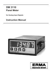
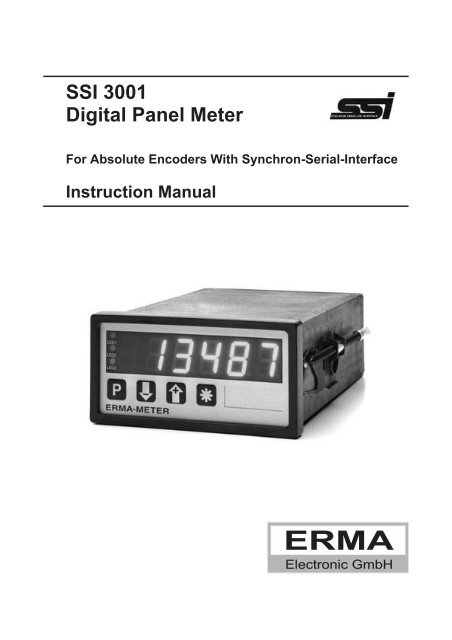
SSI 3001<br />
Digital Panel Meter<br />
For Absolute Encoders With Synchron-Serial-Interface<br />
Instruction Manual<br />
E<strong>RMA</strong><br />
<strong>Electronic</strong> <strong>GmbH</strong>
Warranty<br />
For delivered products our "Allgemeine Lieferungs- und Zahlungsbedingungen" are effective.<br />
In no event E<strong>RMA</strong>-<strong>Electronic</strong> or its suppliers shall be liable for any other damages whatsoever<br />
(including, without limitation, damages for loss of business profits, business interruption or<br />
other pecuniary loss) arising out of or inability to use this product.<br />
All products from E<strong>RMA</strong>-<strong>Electronic</strong> are warranted against defective material and workmanship<br />
for a period of two (2) years from date of delivery. If it is necessary to return the product to E<strong>RMA</strong>,<br />
the sender is responsible for shipping charges, freight, insurance and proper packaging to prevent<br />
breakage in transit. E<strong>RMA</strong>'s warranty does not apply to defects resulting from action of the<br />
buyer, such mishandling, improper interfacing, operation outside of design limits, improper repair<br />
or unauthorized modification.<br />
Trademarks<br />
All trademarks they are named ore portrayed in the text are registered trademarks of its<br />
owner. The trademarks are recognized by E<strong>RMA</strong>-<strong>Electronic</strong>.
CONTENTS<br />
1. Description . . . . . . . . . . . . . . . . . . . . . . . . . . . 5<br />
2. Safety instructions . . . . . . . . . . . . . . . . . . . . . . . 6<br />
2.1. Symbol explanation . . . . . . . . . . . . . . . . . . . . 6<br />
3. Mounting . . . . . . . . . . . . . . . . . . . . . . . . . . . . 7<br />
3.1. Place of operation . . . . . . . . . . . . . . . . . . . . . 7<br />
3.2. Mounting of digital panel meter . . . . . . . . . . . . . . 7<br />
3.2.1. Housing for switch board . . . . . . . . . . . . . 7<br />
3.2.2. Housing for mosaic systems . . . . . . . . . . . 8<br />
4. Electrical connections . . . . . . . . . . . . . . . . . . . . . 9<br />
4.1. General instructions . . . . . . . . . . . . . . . . . . . . 9<br />
4.2. Hints against noisy environment . . . . . . . . . . . . . . 9<br />
4.3. Connection and pin assignment . . . . . . . . . . . . . . 10<br />
4.4. Connection of absolute encoder . . . . . . . . . . . . . . 11<br />
4.5. Connection of digital user inputs . . . . . . . . . . . . . . 11<br />
4.6. Connection of alarm outputs (relay) . . . . . . . . . . . . 11<br />
4.7. Connection of accessory power supply output . . . . . . 12<br />
4.8. Connection of analog output . . . . . . . . . . . . . . . . 12<br />
4.9. Connection of RS 485 interface . . . . . . . . . . . . . . 12<br />
4.10. Connection of RS 232 interface . . . . . . . . . . . . . . 12<br />
4.11. Connection of Current-Loop interface . . . . . . . . . . . 13<br />
4.12. Connection of power supply voltage . . . . . . . . . . . . 13<br />
4.12.1. Supply voltage 95 ... 250 V AC . . . . . . . . . . 13<br />
4.12.2. Supply voltage 18 ... 36 V DC . . . . . . . . . . . 13<br />
5. Startup procedure . . . . . . . . . . . . . . . . . . . . . . . 14<br />
6. Pushbuttons- and LED-functions . . . . . . . . . . . . . . . 15<br />
6.1. Function of buttons and LEDs . . . . . . . . . . . . . . . 15<br />
7. Modes . . . . . . . . . . . . . . . . . . . . . . . . . . . . . . 16<br />
7.1. Operation level . . . . . . . . . . . . . . . . . . . . . . . 16<br />
7.2. Access-code level . . . . . . . . . . . . . . . . . . . . . 17<br />
7.3. Programming level . . . . . . . . . . . . . . . . . . . . . 18<br />
E<strong>RMA</strong>-<strong>Electronic</strong> <strong>GmbH</strong> 2
8. Procedure of programming . . . . . . . . . . . . . . . . . . 19<br />
8.1. Changing or controlling parameters . . . . . . . . . . . . 19<br />
8.2. Overview of the programming levels . . . . . . . . . . . 20<br />
8.3. Programming level for configuration P-00 . . . . . . . . . 21<br />
8.3.1. Scaling the display range . . . . . . . . . . . . . 23<br />
8.4. Programming level of alarms P-02 . . . . . . . . . . . . 24<br />
8.4.1. Alarm output functions . . . . . . . . . . . . . . . 26<br />
8.4.2. Alarm high setpoint . . . . . . . . . . . . . . . . 27<br />
8.4.3. Alarm low setpoint . . . . . . . . . . . . . . . . . 27<br />
8.5. Programming level for analog output P-03 . . . . . . . . 28<br />
8.5.1. Scaling of the analog output . . . . . . . . . . . . 28<br />
8.5.2. Analog output at failure Indication . . . . . . . . 29<br />
8.5.3. Analog output at overflow resp. underflow . . . . 29<br />
8.6. Programming level of serial interface P-04 . . . . . . . . 30<br />
8.6.1. Transmission-Mode . . . . . . . . . . . . . . . . 30<br />
8.6.2. Overview of serial interfaces . . . . . . . . . . . 31<br />
8.7. Programming quick reference . . . . . . . . . . . . . . . 32<br />
9. Software functions . . . . . . . . . . . . . . . . . . . . . . . 34<br />
9.1. Master/Slave-Mode . . . . . . . . . . . . . . . . . . . . 34<br />
9.2. Zero point adjustment . . . . . . . . . . . . . . . . . . . 34<br />
9.2.1. Zero point adjustment by pressing button . . . . . 34<br />
9.2.2. Zero point adjustment by offset value . . . . . . . 35<br />
9.3. Incremental measurement . . . . . . . . . . . . . . . . . 36<br />
9.4. Direction of rotation . . . . . . . . . . . . . . . . . . . . 36<br />
9.5. MIN/MAX value detection . . . . . . . . . . . . . . . . . 36<br />
9.6. Hold function . . . . . . . . . . . . . . . . . . . . . . . . 37<br />
9.7. Display test . . . . . . . . . . . . . . . . . . . . . . . . 37<br />
9.8. Main reset . . . . . . . . . . . . . . . . . . . . . . . . . 38<br />
10. Error codes . . . . . . . . . . . . . . . . . . . . . . . . . . . 38<br />
10.1. Encoder not connected “Err01" . . . . . . . . . . . . . . 38<br />
10.2. Waiting for data input “Err02" . . . . . . . . . . . . . . . 38<br />
10.3. External clock frequency too high “Err03" . . . . . . . . . 38<br />
11. Technical Specifications . . . . . . . . . . . . . . . . . . . . 39<br />
3 E<strong>RMA</strong>-<strong>Electronic</strong> <strong>GmbH</strong>
11.1. Electrical datas . . . . . . . . . . . . . . . . . . . . . . 39<br />
11.2. Mechanical datas . . . . . . . . . . . . . . . . . . . . . 40<br />
11.3. Environmental conditions . . . . . . . . . . . . . . . . . 40<br />
12. Ordering Information . . . . . . . . . . . . . . . . . . . . . . 41<br />
Stand : 03.12.02<br />
SI3001DE.PUB<br />
Technical subjects to change<br />
E<strong>RMA</strong>-<strong>Electronic</strong> <strong>GmbH</strong> 4
1. Description<br />
The digital panel meter Model SSI 3001 is an instrument for displaying and controlling<br />
absolute encoders with Synchronous-Serial-Interface (SSI)<br />
Standard hardware<br />
two relay alarm outputs<br />
two programmable digital input channels<br />
three programmable pushbuttons<br />
Standard software<br />
Programming of encoder datas<br />
Scaling-factor<br />
Zero point adjustment<br />
Offset value<br />
Display segment test<br />
Hold function<br />
MAX/MIN value detection<br />
Auto-Reset of MAX/MIN value<br />
Edit of the alarm value during normal measurement<br />
Display of error messages<br />
Following options are available<br />
analog output 0 - 10 V, 2 - 10 V, 0 - 20 mA, 4 - 20 mA<br />
two additional relay alarm outputs<br />
RS485 interface<br />
RS232 interface<br />
TTY, Current-Loop interface<br />
1. Description<br />
5 E<strong>RMA</strong>-<strong>Electronic</strong> <strong>GmbH</strong>
2. Safety instructions<br />
This instrument is produced in accordance with Class II of IEC 348 and VDE 0411.<br />
When delivered the instrument has been tested to meet all functions described.<br />
Before installing the instrument please read the mounting and servicing instructions.<br />
We have no liability or responsibility to customer or any other person or entity with<br />
respect to any liability, loss or damage caused or alleged to be caused directly or<br />
indirectly by equipment or software sold or furnished by us. Read the installation<br />
instruction carefully. No liability will be assumed for any damage caused by improper<br />
installation.<br />
Inspect the instrument module carton for obvious damage. Be shure there are no<br />
shipping and handing damages on the module before processing. Do not apply power<br />
to the instrument if it has been damaged.<br />
E<strong>RMA</strong>’s warranty does not apply to defects resulting from action of the buyer, such<br />
as mishandling, improper interfacing, operation outside of design limits, improper<br />
repair or unauthorized modifications.<br />
2.1. Symbol explanation<br />
Caution: Will be used at dangerous for life and health !<br />
Attention: Will cause damage<br />
2. Safety instructions<br />
Caution Attention Instruction Tip<br />
Instruction: If not noticed, trouble may occur<br />
Tip: Useful hints for better operation<br />
E<strong>RMA</strong>-<strong>Electronic</strong> <strong>GmbH</strong> 6
3. Mounting<br />
3.1. Place of operation<br />
Attention must be payed to the protection against humidity, dust and high temperatures<br />
at the place of operation.<br />
3.2. Mounting of digital panel meter<br />
3.2.1. Housing for switch board<br />
Insert the case into the panel cutout (according to DIN 43700: 92 +0,8 x45 +0,6 mm)<br />
Tighten the screws alternately, using enough pressure to get good retention and<br />
sealing at the panel.<br />
48,0<br />
45,0 +0,6<br />
LED1<br />
LED2<br />
LED3<br />
P<br />
E<strong>RMA</strong>-METER<br />
Panel Cutout<br />
DIN 43700<br />
96,0<br />
92,0 +0.8<br />
mm<br />
3. Mounting<br />
42,4<br />
89,5<br />
14,7<br />
141,0<br />
7 E<strong>RMA</strong>-<strong>Electronic</strong> <strong>GmbH</strong><br />
8,0
3.2.2. Housing for mosaic systems<br />
Insert the case into one of the following mosaic-systems:<br />
48,0<br />
a) Mosaic-system 8RU (M50x25) of Siemens<br />
b) Mosaic-system of Subklev<br />
LED1<br />
LED2<br />
LED3<br />
P<br />
E<strong>RMA</strong>-METER<br />
Mosaic-Systems:<br />
96,0<br />
Siemens 8RU (M50x25)<br />
Subklev<br />
mm<br />
3. Mounting<br />
42,4<br />
89,5<br />
14,7<br />
141,0<br />
E<strong>RMA</strong>-<strong>Electronic</strong> <strong>GmbH</strong> 8<br />
8,0
4. Electrical connections<br />
4.1. General instructions<br />
4. Electrical connections<br />
It is forbidden to plug or unplug connectors with voltage applied<br />
Attach input and output wires to the connectors only without voltages<br />
applied<br />
Cords must be provided with sleeves<br />
Attention must be paid that the power supply voltage applied will<br />
agree with voltage noticed at the name plate.<br />
The instrument has no power-on switch, so it will be in operation as<br />
soon as the power is connected.<br />
4.2. Hints against noisy environment<br />
All inputs and outputs are protected against noisy environment and high voltage<br />
spikes. Nevertheless the location should be selected to ensure that no capacitive or<br />
inductive interference can have an effect on the instrument or the connection lines.<br />
It is advisable:<br />
To use shielded cables.<br />
The wiring of shields and ground (0V) should be star-shaped.<br />
The distance to interference sources should be as long as possible.<br />
If necessary, protective screen or metal enclosures must be provided.<br />
Coils of relays must be supplied with filters.<br />
Parallel wiring of input signals and AC power lines should be avoided.<br />
9 E<strong>RMA</strong>-<strong>Electronic</strong> <strong>GmbH</strong>
4.3. Connection and pin assignment<br />
All inputs and outputs are connectors, designed as plug-in screw terminals.<br />
Pin assignment:<br />
signal inputs analog output<br />
16 17 18 19 20 21 22 23 24 25 26 27 28 29 30 31<br />
1 2 3 4 5 6 7 8<br />
RS485<br />
4. Electrical connections<br />
digital<br />
inputs<br />
-<br />
+<br />
sensorsupply<br />
9 10 11 12 13 14 15<br />
alarm 1 alarm 2<br />
1 RS 485, GND 16<br />
2 RS 485, B (-) to Signal input SSI<br />
3 RS 485, A (+) 23<br />
4 GND of digital inputs 24 Option analog output<br />
5 Digital user input 1 or option RS 232 interface<br />
6 Digital user input 2 to or option Current-Loop, TTY interface<br />
7 Accessory power supply output (-) or option two additional alarm outputs,<br />
8 Accessory power supply output (+) 31 relays<br />
9/10 Alarm (relay) output 1<br />
11/12 Alarm (relay) output 2<br />
13 Ground connection<br />
14 Power supply L, DC (-)<br />
15 Power supply N, DC (+)<br />
E<strong>RMA</strong>-<strong>Electronic</strong> <strong>GmbH</strong> 10<br />
L N
4.4. Connection of absolute encoder<br />
Encoder<br />
SSI<br />
4.5. Connection of digital user inputs<br />
Digital input 1<br />
active => Connecting Screw Terminal 4 to 5<br />
Connecting to Ground, low active<br />
Digital input 2<br />
active => Connecting Screw Terminal 4 to 6<br />
Connecting to Ground, low-active<br />
4.6. Connection of alarm outputs (relay)<br />
alarm 1 alarm 2<br />
4. Electrical connections<br />
1 2 3 4 5 6 7 8<br />
9 10 11 12 13 14 15<br />
optional<br />
alarm 3 alarm 4<br />
24 25 26 27<br />
8 7<br />
16 17 18 19 20 21 22 23<br />
24 V DC<br />
GND (0 V)<br />
clock (-)<br />
clock (+)<br />
data (+)<br />
data (-)<br />
GND (0 V)<br />
11 E<strong>RMA</strong>-<strong>Electronic</strong> <strong>GmbH</strong>
4.7. Connection of accessory power supply output<br />
24 V DC (only at AC-Version)<br />
1 2 3 4 5 6 7 8<br />
4.8. Connection of analog output<br />
voltage 0(2) .. 10 V current 0(4) .. 20 mA<br />
24 25 26 27 28 29 30 31 24 25 26 27 28 29 30 31<br />
4.9. Connection of RS 485 interface<br />
2 3 4 5 6 7 8<br />
1<br />
A(+)<br />
B(-)<br />
GND<br />
4.10. Connection of RS 232 interface<br />
24 25 26 27 28 29 30 31<br />
GND<br />
TxD<br />
RxD<br />
RTS<br />
CTS<br />
4. Electrical connections<br />
25-pin. 9-pin.<br />
7 GND 5 GND<br />
2 TxD 3 TxD<br />
3 RxD 2 RxD<br />
4RTS 7RTS<br />
-<br />
+<br />
+ - + -<br />
25 26 27 28 29 30 31<br />
5 CTS 8 CTS<br />
6 6<br />
8 1<br />
20 4 24<br />
GND<br />
TxD<br />
RxD<br />
with Handshake without Handshake<br />
A<br />
B<br />
A<br />
B<br />
25-pin. 9-pin.<br />
7 GND 5 GND<br />
2 TxD 3 TxD<br />
3 RxD 2 RxD<br />
4 RTS 7 RTS<br />
5 CTS 8 CTS<br />
6 6<br />
8 1<br />
20 4<br />
E<strong>RMA</strong>-<strong>Electronic</strong> <strong>GmbH</strong> 12
4.11. Connection of Current-Loop interface<br />
31<br />
30<br />
29<br />
28<br />
27<br />
26<br />
25<br />
24<br />
full-duplex, instrument TxD activ, RxD passiv full-duplex, instrument TxD & RxD passiv<br />
31<br />
30<br />
29<br />
28<br />
27<br />
26<br />
25<br />
24<br />
4. Electrical connections<br />
half-duplex, instrument aktiv half-duplex, instrument passiv<br />
4.12. Connection of power supply voltage<br />
4.12.1. Supply voltage 95 ... 250 V AC<br />
9 10 11 12 13 14 15<br />
L N<br />
4.12.2. Supply voltage 18 ... 36 V DC<br />
9 10 11 12 13 14 15<br />
13 E<strong>RMA</strong>-<strong>Electronic</strong> <strong>GmbH</strong><br />
- +<br />
31<br />
30<br />
29<br />
28<br />
27<br />
26<br />
25<br />
24<br />
31<br />
30<br />
29<br />
28<br />
27<br />
26<br />
25<br />
24
5. Startup procedure<br />
5. Startup procedure<br />
Attention must be paid that the power supply voltage applied will agree with<br />
the voltage noticed at the name plate. Switch the power supply on (supply<br />
voltage applied to 14 and 15). After about 2 seconds the display will indicate<br />
the applied input signal.<br />
When delivered, the instrument is programmed with a standard configuration<br />
(default values). By programming the customer can change the standard<br />
configuration according to his measuring task.<br />
Attention ! When the instrument is built in a machine and the customer<br />
wants to change the configuration, attention must be paid, that no damage<br />
will occur to the machine!<br />
E<strong>RMA</strong>-<strong>Electronic</strong> <strong>GmbH</strong> 14
6. Pushbuttons- and LED-functions<br />
There are four push buttons in the front. These push buttons can have different<br />
functions. The functions of the push buttons can be used for programming and for<br />
service.<br />
6.1. Function of buttons and LEDs<br />
LED1<br />
LED2<br />
LED3<br />
P<br />
E<strong>RMA</strong>-METER<br />
LED 1 LED 2 LED 3 Description<br />
x x off encoder- or hold value is displayed<br />
x x red MIN value is displayed<br />
x x green MAX value is displayed<br />
x x green/flashs programming mode is activated<br />
x off x alarm 2 is not activated<br />
x lights x alarm 2 is activated<br />
x flashs off alarm point 2 is displayed<br />
x flashs green/flashs alarm point 2 is changed<br />
off x x alarm 1 is not activated<br />
lights x x alarm 1 is activated<br />
flashs x off alarm point 1 is displayed<br />
flashs x green/flashs alarm point 1 is changed<br />
x = state of the LED is not considered<br />
LED1<br />
LED2<br />
LED3<br />
mm<br />
6 decades display<br />
insertion shield<br />
for dimension<br />
programming button function button<br />
button "-" / alarm 1 / alarm 2<br />
direct input-, average-, max-,<br />
min- or hold value<br />
button "+" / alarm 1 / alarm 2<br />
direct input-, average-, max-,<br />
min- or hold value<br />
6. Pushbuttons- and LED-functions<br />
15 E<strong>RMA</strong>-<strong>Electronic</strong> <strong>GmbH</strong>
7. Modes<br />
7. Modes<br />
The operation and the programming of the panel meter is organized in several states:<br />
Operation level<br />
Access-code level<br />
Programm level<br />
7.1. Operation level<br />
In the state “operation level” the normal functions of the instrument are activated. A<br />
normal measurement cycle looks like below:<br />
Read the value of encoder, calculate and display<br />
Evaluate the digital inputs<br />
Alarm outputs,Analog outputs and serial interface outputs<br />
Dependent on the programming of the parameter 0-14 (function of key ), 0-15<br />
(function of key ) and 0-13 (function of key ), following key-functions are<br />
available in the operation level.<br />
Parameter 0-13<br />
Function of pushbutton “*”<br />
By pressing<br />
0 No function<br />
1 Reset the MIN/MAX value<br />
2 Taring<br />
3 Clear tara value<br />
4 Incremental measurement<br />
5 Manual reset of alarms<br />
6 start single serial transmission<br />
Parameter 0-14<br />
Function of pushbutton “-”<br />
By pressing Pressing during 3 sec.<br />
0 No function -<br />
1 Display value of encoder -<br />
2 Display MAX value -<br />
3 Display MIN value -<br />
4 Display hold value -<br />
5 Display alarm point 1 Change alarm point 1<br />
6 Display alarm point 2 Change alarm point 2<br />
E<strong>RMA</strong>-<strong>Electronic</strong> <strong>GmbH</strong> 16
Parameter 0-15<br />
Function of pushbutton “+”<br />
By pressing Pressing during 3 sec.<br />
0 No function -<br />
1 Display value of encoder -<br />
2 Display MAX value -<br />
3 Display MIN value -<br />
4 Display hold value -<br />
5 Display alarm point 1 Change alarm point 1<br />
6 Display alarm point 2 Change alarm point 2<br />
7.2. Access-code level<br />
The state “access-code level” becomes active by pressing the pushbutton P during<br />
the state “operation level”. The display shows “c000". During the state ”access-code<br />
level" the normal functions of the instrument are active.<br />
pushbutton Function<br />
P Confirm of the displayed access-code<br />
Increase the access-code<br />
Decrease the access-code<br />
Programmed function<br />
7. Modes<br />
17 E<strong>RMA</strong>-<strong>Electronic</strong> <strong>GmbH</strong>
7.3. Programming level<br />
The state “programm level” becomes active by entering the right access-code. The<br />
access-code must be confirm by pressing the pushbutton<br />
organized in following steps:<br />
Selection of a programming level<br />
Selection of a parameter<br />
Change of the selected parameter<br />
P . The programming is<br />
Pushbutton Press<br />
Selection of<br />
Pressing during 3 sec.<br />
P - Programming level<br />
- Parameter<br />
Decrease of<br />
-<br />
- Programming level<br />
- Number of parameter<br />
- Value of parameter<br />
-<br />
Increase of<br />
- Programming level<br />
- Number of parameter<br />
- Value of parameter<br />
7. Modes<br />
- Break the programming routine<br />
E<strong>RMA</strong>-<strong>Electronic</strong> <strong>GmbH</strong> 18<br />
-
8. Procedure of programming<br />
The procedure of programming is organized in several different steps.<br />
Access to the selection of the programming levels<br />
Pressing pushbutton P => access-code enter is active<br />
The display shows “c000"<br />
Changing the access-code by pressing the pushbutton or and confirm<br />
the changed access-code by pressing the pushbutton P<br />
If the entered access-code is not correct, the instrument will jump back to the state<br />
“operation level”.<br />
8.1. Changing or controlling parameters<br />
Activating the programming routine<br />
Pressing pushbutton P<br />
LED 3 flashs green<br />
The display shows “c000"<br />
Changing the access-code by pressing the pushbutton or<br />
Confirm access-code by pressing the pushbutton<br />
The display shows “P-00"<br />
Leaving the programming routine<br />
Pressing the pushbutton or until the display shows “PEnd”<br />
Confirm the display “PEnd” by pressing the pushbutton<br />
LED 3 is off<br />
The active state of the panel meter is “operation level”<br />
Selection of the programming level<br />
8. Procedure of programming<br />
Selecting the programming level by pressing the pushbutton or<br />
Confirm the programming level by pressing the pushbutton P<br />
The display shows the number of the parameter of the selected programming level<br />
For example: “0-00" => parameter 0 of the programming level 0<br />
For example: ”2-00" => parameter 0 of the programming level 2<br />
19 E<strong>RMA</strong>-<strong>Electronic</strong> <strong>GmbH</strong><br />
P<br />
P
Leaving the programming level<br />
Pressing the pushbutton or until the display shows “xEnd”<br />
For example: “0End” => leaving programming level 0<br />
For example: “2End” => leaving programming level 2<br />
Confirm the display “xEnd” by pressing the pushbutton<br />
The display shows the programming level<br />
For example: “P-00" => for programming level 0<br />
For example: ”P-02" => for programming level 2<br />
Selection of the parameter<br />
8. Procedure of programming<br />
Selection the parameter by pressing the pushbutton or<br />
Confirm the parameter by pressing the pushbutton P<br />
The display shows the last programmed value of the selected parameter<br />
Change and controll the selected parameter<br />
Change the value of the parameter by pressing the pushbutton or<br />
Confirm the value of the parameter by pressing the pushbutton P<br />
The display shows the programming level and the number of the parameter<br />
For example: “0-05" => parameter number 5 of programming level 0<br />
For example: ”2-08" => parameter number 8 of programming level 2<br />
8.2. Overview of the programming levels<br />
The parameters of the panel meter are organized in different programming levels.<br />
According to the design of the panel meter there are several programming levels<br />
available.<br />
P-00: Programming level for configuration of the panel meter<br />
The configuration is used to adapt the absolute encoder and the panel meter.<br />
P-02: Programming level for the alarms<br />
This programming level is used to programm all settings for the alarm outputs.<br />
P-03: Programming level for the analog output<br />
This programming level is used to programm all settings of the analog output.<br />
P-04: Programming level of the serial interface<br />
This programming level is used to programm the address and baud rate of the serial<br />
interace.<br />
E<strong>RMA</strong>-<strong>Electronic</strong> <strong>GmbH</strong> 20<br />
P
8. Procedure of programming<br />
8.3. Programming level for configuration P-00<br />
Param. Description Setting range<br />
Default<br />
value<br />
0-00 Resolution (Bits)<br />
Output code<br />
10 .. 25 12<br />
0-01 0 -> Gray<br />
0..1 0<br />
1 -> Binary<br />
Master/Slave-Mode<br />
0-02 0 -> Instrument = Master<br />
0..1 0<br />
1 -> Instrument = Slave<br />
Clock for Master-Mode<br />
0-03 0 -> Frequency = 200 kHz<br />
0..1 0<br />
1 -> Frequency = 100 kHz<br />
Zero adjustment<br />
0-04 0 -> Zero adjustment without sign<br />
0..1 0<br />
1 -> Zero adjustment with ± display<br />
Counting direction<br />
0-05 0 -> increasing clockwise rotation<br />
0..1 0<br />
1 -> increasing anticlockwise rotation<br />
0-06 Scalingfactor 0.00001 .. 9.99999 1.00000<br />
0-07 Offset value<br />
Programmable decimal points<br />
-99999 .. 999999 0<br />
0 -> XXXXXX<br />
1 -> XXXXX.X<br />
0-08 2 -> XXXX.XX<br />
0..5 0<br />
3 -> XXX.XXX<br />
4 -> XX.XXXX<br />
5 -> X.XXXXX<br />
Data source of the display<br />
0 -> Encoder value<br />
0-09 1 -> MAX value<br />
0..3 0<br />
2 -> MIN value<br />
3 -> Hold value<br />
Reset time of the MIN/MAX value<br />
0-10 0 -> No automatically reset<br />
0..100 0<br />
X -> Reset time in seconds<br />
Function of digital user input 1<br />
0 -> No function<br />
0-11<br />
1 -><br />
2 -><br />
Reset MIN/MAX value<br />
Taring of encoder<br />
0..10 0<br />
3 -> Clear tara value of encoder<br />
4 -> Incremental measurement<br />
21 E<strong>RMA</strong>-<strong>Electronic</strong> <strong>GmbH</strong>
Param. Description Setting range<br />
0-11<br />
0-12<br />
0-13<br />
0-14<br />
8. Procedure of programming<br />
continue of 0-11:<br />
Function of digital input 1<br />
5 -> Manual reset of alarms<br />
6 -> Hold function<br />
7 -> Display test<br />
8 -> Display value of encoder<br />
9 -> Display MAX value<br />
10 -> Display MIN value<br />
11 -> start single serial transmission<br />
Function of digital user input 2<br />
0 -> No function<br />
1 -> Reset MIN/MAX value<br />
2 -> Taring of encoder<br />
3 -> Clear tara value of encoder<br />
4 -> Incremental measurement<br />
5 -> Manual reset of alarms<br />
6 -> Hold function<br />
7 -> Display test<br />
8 -> Display value of encoder<br />
9 -> Display MAX value<br />
10 -> Display MIN value<br />
11 -> start single serial transmission<br />
Function of push button “*”<br />
0 -> No function<br />
1 -> Reset MIN/MAX value<br />
2 -> Taring of encoder<br />
3 -> Clear tara value of encoder<br />
4 -> Incremental measurement<br />
5 -> Manual reset of alarm<br />
6 -> start single serial transmission<br />
Function of pushbutton “-”<br />
0 -> No function<br />
1 -> Display value of encoder<br />
2 -> Display MAX value<br />
3 -> Display MIN value<br />
4 -> Display hold value<br />
5 -> Display/change alarm point 1<br />
6 -> Display/change alarm point 2<br />
Default<br />
value<br />
0..11 0<br />
0..11 0<br />
0..6 0<br />
0..6 0<br />
E<strong>RMA</strong>-<strong>Electronic</strong> <strong>GmbH</strong> 22
8. Procedure of programming<br />
Param. Description<br />
Function of pushbutton “+”<br />
Setting range<br />
Default<br />
value<br />
0 -> No function<br />
1 -> Display value of encoder<br />
0-15<br />
2 -><br />
3 -><br />
Display MAX value<br />
Display MIN value<br />
0..6 0<br />
4 -> Display hold value<br />
5 -> Display/change alarm point 1<br />
6 -> Display/change alarm point 2<br />
0-16 Access-code 0 .. 999 0<br />
0End Leaving programming level 0<br />
8.3.1. Scaling the display range<br />
The scaling of the display range is matched by using a scaling-factor and an offset<br />
value. The calculation of the display value looks like below:<br />
Display = (Enc_value - Zero_adjustmet) x Sca_faktor + Offset value<br />
The overflow or underflow becomes active, if the displayed value is greater than<br />
999999 or smaller than -99999.<br />
When overflow is activ the display shows “nnnnnn”<br />
When underflow is active the display shows “uuuuuu”<br />
23 E<strong>RMA</strong>-<strong>Electronic</strong> <strong>GmbH</strong>
8.4. Programming level of alarms P-02<br />
Param. Description Setting range<br />
2-00<br />
2-01<br />
Alarm output 1, data source<br />
0 -> Alarm 1 off<br />
1 -> Alarm 1 to value of encoder<br />
2 -> Alarm 1 to maximum value<br />
3 -> Alarm 1 to minimum value<br />
4 -> Alarm 1 to hold value<br />
Alarm output 1, high or low<br />
0 -> Contact closed by low limit<br />
1 -> Contact closed by high limit<br />
2 -> Contact open by low limit<br />
3 -> Contact open by high limit<br />
Default<br />
value<br />
0..4 0<br />
0..3 0<br />
2-02 Alarm output 1, alarm point -99999 .. 999999 0<br />
2-03 Alarm output 1, hysteresis 1 .. 1000 1<br />
2-04<br />
2-05<br />
2-06<br />
2-07<br />
Alarm output 1, release delay time<br />
in seconds<br />
Alarm output 1, operate delay time<br />
in seconds<br />
Alarm output 2, data source<br />
0 -> Alarm 2 off<br />
1 -> Alarm 2 to value of encoder<br />
2 -> Alarm 2 to maximum value<br />
3 -> Alarm 2 to minimum value<br />
4 -> Alarm 2 to hold value<br />
Alarm output 2, high or low<br />
0 -> Contact closed by low limit<br />
1 -> Contact closed by high limit<br />
2 -> Contact open by low limit<br />
3 -> Contact open by high limit<br />
0..60 0<br />
0..60 0<br />
0..4 0<br />
0..3 0<br />
2-08 Alarm output 2, alarm point -99999 .. 999999 0<br />
2-09 Alarm output 2, hysteresis 1 .. 1000 1<br />
2-10<br />
2-11<br />
8. Procedure of programming<br />
Alarm output 2, release delay time<br />
in seconds<br />
Alarm output 2, operate delay time<br />
in seconds<br />
0..60 0<br />
0..60 0<br />
E<strong>RMA</strong>-<strong>Electronic</strong> <strong>GmbH</strong> 24
Param. Description Setting range<br />
2-12<br />
2-13<br />
Alarm output 3, data source<br />
0 -> Alarm 3 off<br />
1 -> Alarm 3 to value of encoder<br />
2 -> Alarm 3 to maximum value<br />
3 -> Alarm 3 to minimum value<br />
4 -> Alarm 3 to hold value<br />
Alarm output 3, high or low<br />
0 -> Contact closed by low limit<br />
1 -> Contact closed by high limit<br />
2 -> Contact open by low limit<br />
3 -> Contact open by high limit<br />
Default<br />
value<br />
0..4 0<br />
0..3 0<br />
2-14 Alarm output 3, alarm point -99999 .. 999999 0<br />
2-15 Alarm output 3, hysteresis 1 .. 1000 1<br />
2-16<br />
2-17<br />
2-18<br />
2-19<br />
Alarm output 3, release delay time<br />
in seconds<br />
Alarm output 3, operate delay time<br />
in seconds<br />
Alarm output 4, data source<br />
0 -> Alarm 4 off<br />
1 -> Alarm 4 to value of encoder<br />
2 -> Alarm 4 to maximum value<br />
3 -> Alarm 4 to minimum value<br />
4 -> Alarm 4 to hold value<br />
Alarm output 4, high or low<br />
0 -> Contact closed by low limit<br />
1 -> Contact closed by high limit<br />
2 -> Contact open by low limit<br />
3 -> Contact open by high limit<br />
0..60 0<br />
0..60 0<br />
0..4 0<br />
0..3 0<br />
2-20 Alarm output 4, alarm point -99999 .. 999999 0<br />
2-21 Alarm output 4, hysteresis 1 .. 1000 1<br />
2-22<br />
8. Procedure of programming<br />
Alarm output 4, release delay time<br />
in seconds<br />
2-23<br />
Alarm output 4, operate delay time<br />
in seconds<br />
2End Leave programming level P-02<br />
0..60 0<br />
0..60 0<br />
25 E<strong>RMA</strong>-<strong>Electronic</strong> <strong>GmbH</strong>
8.4.1. Alarm output functions<br />
Data sources of the alarms:<br />
Value of the encoder<br />
Maximum value<br />
Minimum value<br />
Hold value<br />
Indication of alarms<br />
Two relay output, LED 1 and LED 2 at the front for alarm output 1 and 2<br />
Two relays for alarm output 3 and 4 (option two additional relay alarm outputs)<br />
Programmable functions of the alarms<br />
Alarm value<br />
Hysteresis<br />
Release delay time and operate delay time<br />
High or low alarm<br />
Manual alarm reset<br />
In dependence of programming the digital inputs and the functional pushbutton<br />
is the alarm output latched or not latched.<br />
Alarm output latched:<br />
If the digital input 1, 2 (parameter 0-11 and 0-12) or the functional pushbutton<br />
(parameter 0-13) is programmed to manual alarm reset<br />
Reset the latched alarm output by activate the digital inputs or press the functional<br />
pushbutton<br />
Alarm output not latched:<br />
8. Procedure of programming<br />
If the digital inputs and the functional pushbutton are not programmed to<br />
manual alarm reset<br />
Display and edit the alarm values 1, 2, 3 and 4<br />
Inside the programmig routine, which is reached over the enter code. During the<br />
programming routine no measurement is taken.<br />
Display and edit the alarm value 1 and 2<br />
Outside the programming routine by pressing the pushbutton<br />
normal measurement are taken.<br />
or during<br />
The edition is end when pressing the pushbutton<br />
will be up to date.<br />
P . Therfore the alarm value<br />
E<strong>RMA</strong>-<strong>Electronic</strong> <strong>GmbH</strong> 26
8.4.2. Alarm high setpoint<br />
normally closed<br />
to high limit<br />
normally opened<br />
to high limit<br />
alarm value<br />
alarm valuehysteresis<br />
8.4.3. Alarm low setpoint<br />
normally closed<br />
to low limit<br />
normally opened<br />
to low limit<br />
alarm value +<br />
hysteresis<br />
alarm value<br />
8. Procedure of programming<br />
LED LED<br />
LED<br />
LED LED<br />
LED<br />
operate delay time release delay time t<br />
LED LED<br />
LED<br />
LED LED<br />
LED<br />
alarm watched<br />
signal<br />
alarm watched<br />
signal<br />
operate delay time release delay time t<br />
27 E<strong>RMA</strong>-<strong>Electronic</strong> <strong>GmbH</strong><br />
t<br />
t<br />
t<br />
t
8.5. Programming level for analog output P-03<br />
The parameters of this programming level P-03 exists only by instruments with the<br />
option analog output.<br />
Param. Description Seeting range<br />
3-00<br />
3-01<br />
3-02<br />
Analog Output, data source<br />
0 -> Value of encoder to analog output<br />
1 -> MAX value to analog output<br />
2 -> MIN value to analog output<br />
3 -> Hold value to analog output<br />
Analog Output, configuration<br />
0 -> 0 to 10 V<br />
1 -> 2 to 10 V<br />
2 -> 0 to 20 mA<br />
3 -> 4 to 20 mA<br />
Display value for minimal analog<br />
output signal<br />
3-03<br />
Display value for maximal analog output<br />
signal<br />
3End Leave programming level P-03<br />
Default<br />
value<br />
0..3 0<br />
0..3 0<br />
-99999 .. 999999 0<br />
-99999 .. 999999 4095<br />
8.5.1. Scaling of the analog output<br />
The scaling of the analog output range can be programmed with the parameter 3-02<br />
and 3-03. Any value between -99999 and 999999 can be set to minimal and maximal<br />
analog output signal.<br />
Data sources of the analog output:<br />
Value of encoder<br />
Maximum value<br />
Minimum value<br />
Hold value<br />
8. Procedure of programming<br />
E<strong>RMA</strong>-<strong>Electronic</strong> <strong>GmbH</strong> 28
8.5.2. Analog output at failure Indication<br />
Output signal<br />
Output value by<br />
“Err01"<br />
Voltage 0 to 10 V 0 V<br />
Voltage 2 to 10 V 1 V<br />
Current 0 to 20 mA 0 mA<br />
Current 4 to 20 mA 2 mA<br />
8.5.3. Analog output at overflow resp. underflow<br />
Output signal<br />
8. Procedure of programming<br />
Output value by<br />
overflow<br />
Output value by<br />
”Err02" and “Err03"<br />
current value won´t be<br />
changed<br />
Output value by<br />
underflow<br />
Voltage 0 to 10 V 10 V 0 V<br />
Voltage 2 to 10 V 10 V 2 V<br />
Current 0 to 20 mA 20 mA 0 mA<br />
Current 4 to 20 mA 20 mA 4 mA<br />
29 E<strong>RMA</strong>-<strong>Electronic</strong> <strong>GmbH</strong>
8.6. Programming level of serial interface P-04<br />
The parameters of this programming level P-04 exists anly by panel meters with the<br />
option serial interface. The interface moduls are bidirectional, isolated of the further<br />
electronic and works at the slave mode.<br />
Param. Description Setting range<br />
Default<br />
values<br />
4-00 Interface address<br />
Interface baud rate<br />
0 .. 31 1<br />
0 -> : 300 baud<br />
1 -> : 600 baud<br />
4-01<br />
2 -><br />
3 -><br />
: 1200 baud<br />
: 2400 baud<br />
0..6 6<br />
4 -> : 4800 baud<br />
5 -> : 9600 baud<br />
6 -> : 19200 aud<br />
Transmission-Mode<br />
4-02<br />
0 -><br />
1 -><br />
PC-Mode<br />
Terminal-Mode timer controlled<br />
0..2 0<br />
2 -> Terminal-Mode button/input controlled<br />
4-03<br />
Sendrate in sec.<br />
0 -> permanent transmission<br />
Data source for serial interface<br />
0..3600 0<br />
0 -> Value of encoder<br />
4-04 1 -> MAX value<br />
0..3 0<br />
2 -> MIN value<br />
3 -> Hold value<br />
Handshake for option RS 232<br />
4-05 0 -> without handshake<br />
0..1 0<br />
1 -> with handshake<br />
4End Leave programming level P-04<br />
The panel meter can be controlled completly wth the serial interface. That means the<br />
panel meter can initialized of a host (unit name, revision number). It can be adjust all<br />
parameters and it can be read all measured values resp. all values of the parameters.<br />
8.6.1. Transmission-Mode<br />
PC-Mode<br />
8. Procedure of programming<br />
In PC-Mode a single transmission is started with a special command from the PC.<br />
A complete list of all possible commands is available as additional manual.<br />
E<strong>RMA</strong>-<strong>Electronic</strong> <strong>GmbH</strong> 30
8. Procedure of programming<br />
Terminal mode by using the timer register<br />
A transmission can initialise by using the timer register (4-03). You can set the register<br />
to 0 sec (transmission by conversion rate) to 3600 sec to get periodical transmission.<br />
Terminal mode by manual data transfer release<br />
A transmission can initialise by using a external contact (0-11 = 11 resp. 0-12 = 11)<br />
or by using the button (0-13 = 6).<br />
8.6.2. Overview of serial interfaces<br />
RS 485 RS 232<br />
Current-Loop, TTY<br />
passive<br />
Mode of transmission symmetrical asymmetrical symmetrical<br />
length of cable max. 1200 m 15 m 300 m<br />
Number of transmitter 32 1 1<br />
Number of receiver 32 1<br />
Number of wires 2 3/5 2<br />
Transmitter output<br />
unused max.<br />
± 5 V ± 15 V 20 mA<br />
Transmitter output<br />
used min.<br />
± 1,5 V ± 5 V 20 mA (*)<br />
Receiver input<br />
min.<br />
± 0,3 V ± 3 V 10 mA<br />
(*) only when maximal burden is not exceeded<br />
31 E<strong>RMA</strong>-<strong>Electronic</strong> <strong>GmbH</strong>
8.7. Programming quick reference<br />
2<br />
0<br />
P<br />
+ -<br />
P<br />
+ -<br />
P<br />
+ -<br />
P<br />
+ -<br />
P<br />
+ -<br />
P<br />
+ -<br />
+ -<br />
P<br />
+ -<br />
P<br />
+ -<br />
P<br />
+ -<br />
P<br />
+ -<br />
P<br />
+ -<br />
P<br />
+ -<br />
P<br />
+ -<br />
P<br />
+ -<br />
P<br />
+ -<br />
+ -<br />
P<br />
+ -<br />
P<br />
+ - P<br />
+ -<br />
P<br />
+ -<br />
P<br />
+ - P<br />
+ -<br />
P<br />
+ -<br />
operation level<br />
Data source of alarm 1<br />
2-00<br />
2-01<br />
2-02<br />
2-03<br />
2-04<br />
2-05<br />
2-06 P<br />
2-07<br />
2-08<br />
2-09<br />
2-10<br />
2-11<br />
2-12<br />
2-13<br />
2-14<br />
2-15<br />
2-16 P<br />
2-17<br />
2-18<br />
2-19<br />
+ -<br />
P Output code:<br />
+ -<br />
P<br />
+ -<br />
P<br />
+ -<br />
P<br />
+ -<br />
P<br />
+ -<br />
+ -<br />
P<br />
+ -<br />
P<br />
+ - P<br />
+ -<br />
+<br />
P<br />
-<br />
-<br />
+<br />
+<br />
P<br />
+ - P<br />
+ -<br />
P<br />
+ - P<br />
+ - P<br />
+ - P<br />
+ -<br />
Resulution (bits)<br />
Alarm 1, high or low<br />
gray or binary<br />
0-00 P<br />
0-01<br />
0-02<br />
0-03<br />
0-04<br />
0-05<br />
wrong<br />
P Code<br />
P<br />
Value of alarm 1<br />
Master/Slave - mode<br />
Hysteresis of alarm 1<br />
Clock for Master-mode<br />
c000<br />
Fall off time of alarm 1<br />
Zero - adjustment<br />
P Code<br />
o.k.<br />
Put on time of alarm 1<br />
Counting derction<br />
0<br />
P<br />
Data source of alarm 2<br />
0-06 P Display - multiplier<br />
1<br />
P-00<br />
Alarm 2, high or low<br />
Offset - value<br />
-<br />
+<br />
8. Procedure of programming<br />
Value of alarm 2<br />
Programmable points<br />
2<br />
P<br />
Hysteresis of alarm 2<br />
Data source of the<br />
display<br />
Reset time of maxmin-<br />
and hold value<br />
Function of digital<br />
input 1<br />
Function of digital<br />
input 2<br />
0-07<br />
0-08<br />
0-09<br />
0-10<br />
0-11<br />
0-12<br />
0-13<br />
0-14<br />
0-15<br />
0-16<br />
0End<br />
3<br />
P-01<br />
Fall off time of alarm 2<br />
-<br />
-<br />
+<br />
Put on time of alarm 2<br />
4<br />
P<br />
P<br />
Data source of alarm 3<br />
5<br />
P-02<br />
Alarm 3, high or low<br />
Function of key "*"<br />
-<br />
+<br />
-<br />
+<br />
Value of alarm 3<br />
Function of key "-"<br />
6<br />
P<br />
Function of key "+"<br />
7<br />
P-03<br />
Hysteresis of alarm 3<br />
Fall off time of alarm 3<br />
access - code<br />
-<br />
+<br />
Put on time of alarm 3<br />
8<br />
P<br />
P<br />
9<br />
P-04<br />
Data source of alarm 4<br />
1<br />
Alarm 4, high or low<br />
-<br />
+<br />
Value of alarm 4<br />
PEnd<br />
Hysteresis of alarm 4<br />
Fall off time of alarm 4<br />
Put on time of alarm 4<br />
2-20<br />
2-21<br />
2-22<br />
2-23<br />
1End<br />
E<strong>RMA</strong>-<strong>Electronic</strong> <strong>GmbH</strong> 32<br />
P<br />
3
8<br />
6<br />
Interface<br />
address<br />
P<br />
P<br />
P<br />
P<br />
P<br />
P<br />
-<br />
-<br />
-<br />
-<br />
-<br />
-<br />
+<br />
+<br />
+<br />
+<br />
+<br />
+<br />
Data source of<br />
analog output<br />
+ -<br />
Analog output signal<br />
P<br />
P<br />
Baud rate<br />
Mode of<br />
transmission<br />
Display value for<br />
min. output signal<br />
Display value for<br />
max. output signal<br />
P<br />
P<br />
3-00<br />
3-01<br />
3-02<br />
3-03<br />
3End<br />
-<br />
-<br />
-<br />
-<br />
+<br />
+<br />
+<br />
+<br />
+ -<br />
8. Procedure of programming<br />
Sendrate<br />
Data source<br />
Handshake<br />
(RS232)<br />
4-00<br />
4-01<br />
4-02<br />
4-03<br />
4-04<br />
4-05<br />
4End<br />
7<br />
description<br />
33 E<strong>RMA</strong>-<strong>Electronic</strong> <strong>GmbH</strong><br />
9<br />
P - pressing the button<br />
P<br />
- pressing the button<br />
+<br />
- pressing the button<br />
-
9. Software functions<br />
9.1. Master/Slave-Mode<br />
9. Software functions<br />
Master-Mode Parameter 0-02 have to be programmed to 0<br />
For reading the value of the encoder the clock is generated by the instrument. The<br />
clock frequency can be programmed to 100 kHz or 200 kHz. (parameter 0-03)<br />
Slave-Mode: Parameter 0-02 have to be programmed to 1<br />
The clock signal have to be generated by an other instrument. The data transmission<br />
between the encoder and the instrument dependent on this “external clock”.<br />
In slave mode attention should be paid to:<br />
External clock may not exceed 125 kHz<br />
Pause of clock brushs have to be min. 500 µs<br />
The encoder value will be displayed with 28 values per second<br />
9.2. Zero point adjustment<br />
Sometimes an exactly mechanical zero point adjustment isn´t possible. But it´s<br />
possible to adjust the zero point by software.<br />
9.2.1. Zero point adjustment by pressing button<br />
The zero point can be changed by pressing the button. Parameter 0-13 have to<br />
be programmed to 2.<br />
1. Zero point adjustment with sign: Parameter 0-04 have to be programmed to 1<br />
Example:<br />
Absolute Encoder SSI-Encoder, singeltur´n<br />
Resolution: 4096 steps per rotation<br />
Display range without changing of the zero point<br />
3072<br />
0<br />
2048<br />
1024<br />
E<strong>RMA</strong>-<strong>Electronic</strong> <strong>GmbH</strong> 34
9. Software functions<br />
Display range with changing of the zero point<br />
The pushbutton have been pressed by a display<br />
of 2048<br />
2. Zero point adjustment without sign: Parameter 0-04 have to be programmed to 0<br />
Example:<br />
Absolute Encoder SSI-Encoder, singleturn<br />
Resolution: 4096 steps per rotation<br />
Display range without changing of the zero point<br />
Display range with changing of the zero point<br />
The pushbutton have been pressed by a display<br />
of 2048<br />
9.2.2. Zero point adjustment by offset value<br />
The calculation of the programmed offset value (parameter 0-07) looks like below:<br />
There can be a ± display, as a result of programming an offset value.<br />
Attention should be paid to:<br />
The charging of the offset value is followed after the charging of the<br />
scaling-factor.<br />
The Parameter 0-04 have to be programmed to 1<br />
1024<br />
3072<br />
1024<br />
2048<br />
0<br />
0<br />
2048<br />
2048<br />
Display = (Enc_yalue - Zero_adjustmet) x Sca_faktor + Offset value<br />
0<br />
-1024<br />
1024<br />
3072<br />
35 E<strong>RMA</strong>-<strong>Electronic</strong> <strong>GmbH</strong>
9. Software functions<br />
9.3. Incremental measurement<br />
A relative measurement can be made by using the incremental measurement<br />
function. Activating the incremental measurement function will happen, that a incremental<br />
measurement value will be stored to a non-volatile EEPROM even after<br />
switching of the instrument.<br />
Activating the incremental measurement function<br />
The digital input 1 (parameter 0-11)<br />
The digital input 2 (parameter 0-12)<br />
The functional pushbutton (parameter 0-13)<br />
Activating the incremental measurement function by pressing the functional pushbutton<br />
or activating digital input 1/digital input 2 (dependent on the programming<br />
of the parameter 0-11, 0-12 and 0-13), cause that the current encoder value is stored<br />
to an EEPROM. This value will be substracted from each current encoder value.<br />
Activating the function a second time will switch off the function and clear the incremtal<br />
measurement value of the EEPROM.<br />
9.4. Direction of rotation<br />
The direction of rotation can be changed by software function. The encoder will<br />
usually count in increasing direction, if the driving shaft turns with clockwise rotation<br />
(top view at the driving shaft).<br />
Increasing values with clockwise rotation (top view at the driving shaft),<br />
Parameter 0-05 have to be programmed to 0<br />
Increasing values with anti-clockwise rotation (top view at the driving shaft),<br />
Parameter 0-05 have to be programmed to 1<br />
9.5. MIN/MAX value detection<br />
The panel meter include a MIN/MAX value detection. The maximum and minimum<br />
value can be displayed with the frontal push buttons or the digital user inputs. Besides<br />
the maximum and minimum value can be controlled of the alarm output or can be<br />
used as the data source for the analog output<br />
Reset the minimum and maximum values:<br />
Automatically by the programmed memory reset time (parameter 0-10)<br />
By activating the digital inputs 1 or 2 (parameter 0-11 and 0-12)<br />
By pressing the functional pushbutton (parameter 0-13)<br />
By leaving the programming routine<br />
E<strong>RMA</strong>-<strong>Electronic</strong> <strong>GmbH</strong> 36
Display the minimum and maximum value<br />
By programming as data source of the display (parameter 0-09)<br />
By activating the digital input 1 or 2 (parameter 0-11 and 0-12)<br />
By pressing the pushbutton or (parameter 0-15 and 0-14)<br />
Indication of the displayed minimum and maximum value<br />
LED 3 lights red => minimum value is displayed<br />
LED 3 lights green => maximum value is displayed<br />
9.6. Hold function<br />
When activating the hold function the value of the data source, which is programmed<br />
in parameter 0-09, is taken over into the hold memory. If the hold function is not active<br />
the hold value is the same as the value of the data source, which is programmed in<br />
parameter 0-09.<br />
Activating the hold function by:<br />
Digital input 1 (parameter 0-11)<br />
Digital input 2 (parameter 0-12)<br />
Reset the hold value<br />
By leaving the programming routine<br />
Display the hold value by<br />
Programming as data source of the display (parameter 0-09)<br />
Pressing the pushbutton or (parameter 0-15 and 0-14)<br />
The hold value can:<br />
Show on display<br />
Watched by alarm output<br />
Set to the analog output<br />
9.7. Display test<br />
When activating the display test all segments of the display are light on. The display<br />
shows “8.8.8.8.8.8.”<br />
Activating the display test by:<br />
Digital input 1 (parameter 0-11)<br />
Digital input 2 (parameter 0-12)<br />
9. Software functions<br />
37 E<strong>RMA</strong>-<strong>Electronic</strong> <strong>GmbH</strong>
9.8. Main reset<br />
The main reset is performed by pressing a key combination at the front of the panel<br />
meter. By doing this all parameters are setting to the default value. The value of the<br />
parameter 0-00 (input range) is not changing by the main reset.<br />
During the main reset the display shows “Init.”.<br />
Perform the main reset by<br />
Pressing the pushbuttons P , and at the same time during 10 seconds.<br />
10. Error codes<br />
10. Error codes<br />
10.1. Encoder not connected “Err01"<br />
The display flashs and indicate “Err01"<br />
Signalizes that no encoder have been connected to the instrument<br />
10.2. Waiting for data input “Err02"<br />
The display flashs and indicate “Err02"<br />
Signalizes in slave-mode, that after the connection of an encoder no data input<br />
have been received by the instrument.<br />
10.3. External clock frequency too high “Err03"<br />
The display flashs and indicate “Err03"<br />
Signalizes in slave mode, that the clock frequency of the “external clock” is too<br />
high (> 125 kHz).<br />
E<strong>RMA</strong>-<strong>Electronic</strong> <strong>GmbH</strong> 38
11. Technical Specifications<br />
11.1. Electrical datas<br />
11. Technical Specifications<br />
SSI signal input : singleturn or multiturn<br />
Resolution : 10 .. 25 bit<br />
Code : binary or gray<br />
Clock output : driverRS 422/485<br />
Clock input : receiver RS 422/485<br />
Data input : receiver RS 422/485<br />
Master mode<br />
Clock frequency : internal, 100 kHz or 200 kHz<br />
Conversion rate : approximate 28 values/second<br />
Slave mode<br />
Clock frequency : external, max. 125 kHz<br />
Break of clock brushs : min. 500 µs<br />
Conversion rate : approximate 28 values/second<br />
Digital user inputs : 10 kΩ to +5 V<br />
Logic : NPN, max. 30 V<br />
Signal level : L-Pegel < 0,4 V<br />
: H-Pegel > 3,5 V<br />
Alarm outputs : 2 relays (programmable as<br />
opened contact or closed contact)<br />
Signaling : 2 LEDs at the front<br />
Switch voltage : 250 V AC / 250 V DC<br />
Switch current : 5 A AC / 5 A DC<br />
Switch power : 750 VA / 100 W<br />
Option analog output : resolution 16 bit<br />
Accuracy : ± 0,2 % of final value<br />
Voltage : 0/2 - 10 V, max. 10 mA<br />
Current : 0/4 - 20 mA, max. 500 Ω<br />
Isolation voltage : 3 kV / 1 min<br />
Option interfaces : RS 485, RS 232, TTY<br />
Protocol : DIN 66 019 / ISO 1745<br />
Baud rate : 300, 1200, 2400, 4800, 9600, 19200<br />
Data format : 1 Start, 8 Data, N-Parity, 1 Stop<br />
Isolation voltage : 1,6 kV / 1 min<br />
Power supply AC : 95 .. 250 V AC<br />
Power consumption : approx. 9 VA<br />
Isolation voltage : 2,5 kV / 1 min<br />
Option power supply DC : 18 .. 36 V DC<br />
Power consumption : approx. 70 mA<br />
39 E<strong>RMA</strong>-<strong>Electronic</strong> <strong>GmbH</strong>
Isolation voltage : 500 V / 1 min<br />
Accessory power supply (only at AC) : 24 V DC ± 10 %, max. 125 mA<br />
Isolation voltage : 500 V / 1 min<br />
11.2. Mechanical datas<br />
11. Technical Specifications<br />
Display : 6 decades, 14 mm, red<br />
: decimal point programmable<br />
: preliminary zero suppression<br />
: - sign at negative values<br />
Operation, keyboard design : front membrane with push buttons<br />
Case : switch board mounting DIN 43 700<br />
Dimensions (B x H x T) : 96 x 48 x 141 mm<br />
Depth : 148 mm incl. screw terminal<br />
Mounting : switch board mounting or<br />
: mosaic-system mounting<br />
Weight : approx. 400 g<br />
Connection : plug-in screw terminal<br />
Signal inputs : max. � 1,5 mm²<br />
Alarm outputs : max. � 2,5 mm²<br />
Power inputs : max. � 2,5 mm²<br />
11.3. Environmental conditions<br />
Operating temperature : 0 .. 50 °C<br />
Storage temperature : -20 .. 70 °C<br />
Humidity : < 80 %, not-condensing<br />
Protection : protection class II<br />
Front protection : IP 54<br />
: connectors IP 20<br />
Field of application : class 2<br />
: overvoltage protection II<br />
CE : in conform with 89/336/EWG<br />
: NSR 73/23/EWG<br />
E<strong>RMA</strong>-<strong>Electronic</strong> <strong>GmbH</strong> 40
12. Ordering Information<br />
SSI 3001 -<br />
12. Ordering Information<br />
Housing<br />
0 Switch board mounting<br />
1 Panel-clip<br />
Front framel color<br />
0 Black<br />
Front design<br />
0 E<strong>RMA</strong>-Meter logo<br />
1 No logo<br />
2 Customer designed logo<br />
Power supply<br />
0 95 .. 250 V AC<br />
1 18 .. 36 V DC<br />
Option interface<br />
0 No interface<br />
1 RS 485<br />
0 2 RS 232<br />
0<br />
Option<br />
3 Current-Loop, TTY<br />
0 No option<br />
1 With analog output<br />
4 2 additional alarm outputs (relay)<br />
41 E<strong>RMA</strong>-<strong>Electronic</strong> <strong>GmbH</strong>
E<strong>RMA</strong> - <strong>Electronic</strong> <strong>GmbH</strong><br />
Max-Eyth-Straße 8<br />
D-78194 Immendingen<br />
Telefon (+49 7462) 7381<br />
Fax (+49 7462) 7554<br />
email erma-electronic@t-online.de<br />
E<strong>RMA</strong><br />
<strong>Electronic</strong> <strong>GmbH</strong>