Central Battery System ZB-S with STAR Technology - CEAG
Central Battery System ZB-S with STAR Technology - CEAG
Central Battery System ZB-S with STAR Technology - CEAG

You also want an ePaper? Increase the reach of your titles
YUMPU automatically turns print PDFs into web optimized ePapers that Google loves.
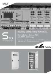
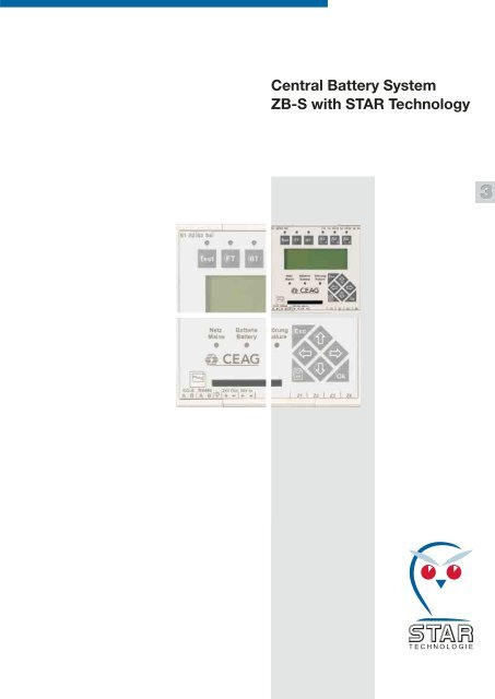
<strong>Central</strong> <strong>Battery</strong> <strong>System</strong><br />
<strong>ZB</strong>-S <strong>with</strong> <strong>STAR</strong> <strong>Technology</strong><br />
<strong>CEAG</strong> Notlichtsysteme GmbH 3/1<br />
3
S = Switching<br />
T = <strong>Technology</strong><br />
A = Advanced<br />
R = Revision<br />
What is <strong>ZB</strong>-S?<br />
Switch to safety!<br />
<strong>ZB</strong>-S is a logical onward development of the<br />
successful <strong>ZB</strong> 96 <strong>Central</strong> <strong>Battery</strong> <strong>System</strong>. For<br />
many years now the <strong>ZB</strong> 96 system has enjoyed<br />
an enviable reputation as a dependable supply<br />
and monitoring system, and features the fully<br />
automatic CEWA Guard function monitoring<br />
and individual monitoring system.<br />
The continuing development of this monitoring<br />
system has led to the creation of the<br />
Switching<br />
<strong>Technology</strong><br />
Advanced<br />
Revision,<br />
or <strong>STAR</strong> for short. This new CG-<strong>STAR</strong> technology<br />
allows different switching modes to be<br />
implemented in one and the same circuit, and<br />
the switching mode of each individual luminaire<br />
can be re-programmed at any time.<br />
As a result, the new technology offers not just<br />
the proven CEWA Guard safety when it comes<br />
to operating a safety lighting system, it also<br />
gives planners the confidence of knowing that<br />
the system can respond and adapt at any time<br />
to any changes that are made to a building and<br />
its use.<br />
<strong>CEAG</strong> Notlichtsysteme GmbH 3/2
DS<br />
DS<br />
BS<br />
BS<br />
BS<br />
BS<br />
DS<br />
DS<br />
The New <strong>STAR</strong>-<strong>Technology</strong> –<br />
Easy Planning<br />
Your Advantages:<br />
The number of outgoing circuits needed can be sharply reduced, since continuously operating,<br />
stand-by and switchable permanent lighting can be realised in one common circuit.<br />
This allows the use of shorter cable distances, reduces installation costs and minimises the<br />
effects of burning materials. Any mode of operation can be assigned at a later date – <strong>with</strong>out<br />
encroachment in the lighting installation. This enables simple project planning <strong>with</strong>out<br />
having to take all possible types of operation into account.<br />
DLS<br />
DLS<br />
DLS<br />
DLS<br />
Conventional Installation:<br />
Maintained light 1 (DS)<br />
Non-maintained light 1 (BS)<br />
Non-maintained light 2 (BS)<br />
Maintained light 2 (DS)<br />
Switched maintained light 1 (DLS)<br />
Switched maintained light 2 (DLS)<br />
■ Each type of switching mode requires two circuits<br />
■ Only one type of switching mode is<br />
possible per circuit<br />
■ Any later modifications involve a large<br />
amount of work and expense<br />
<strong>ZB</strong>-S Installation <strong>with</strong><br />
<strong>STAR</strong>-<strong>Technology</strong>:<br />
All types of switching modes<br />
All types of switching modes<br />
■ Only two outgoing circuits for all types<br />
of switching modes<br />
■ Maintained light, non-maintained<br />
light and switched maintained<br />
light are possible in one common<br />
circuit<br />
■ Later circuit modifications do not pose<br />
any problems<br />
<strong>CEAG</strong> Notlichtsysteme GmbH 3/3<br />
3
Cable entry from top<br />
Three-level neutral line disconnect terminal strips<br />
Control module, DC/DC, charger,<br />
2 x SKU 2 x 3 A CG-S<br />
Circuit change-over module 24 x SKU 2 x 3 A CG-S<br />
Load break switch, mains<br />
Terminal strip mains (optional)<br />
Load break switch, battery<br />
Terminal strip battery (optional)<br />
Boost charger 2.5 A<br />
Cable entry from bottom<br />
Boost chargers each <strong>with</strong> a charging<br />
current of 2.5 A<br />
The LT.1 2,5A charging module drives the boost<br />
chargers to which the standby power batteries that<br />
are installed outside the switch cabinet are connected.<br />
<strong>ZB</strong>-S:<br />
Inspired engineering for the switch cabinet<br />
Plenty of connection space for<br />
convenient wiring<br />
All connections are run to 3-level<br />
neutral disconnect terminals at the<br />
top of the switch cabinet.<br />
<strong>CEAG</strong> Notlichtsysteme GmbH 3/4
separate keys for<br />
Test (emergency function) ■<br />
Function test ■<br />
Duration test ■<br />
Connections for phase<br />
monitor and blocking switch<br />
<strong>with</strong> differential loop<br />
monitoring<br />
LEDs for operation display<br />
Terminals for data bus<br />
separate fuse protection for mains- and battery operation (two-pole)<br />
External DLS/3PH-Bus-Module<br />
for common switching of safety- and general lighting<br />
<strong>ZB</strong>-S:<br />
Inspired engineering for the switch cabinet<br />
Freely programmable control module<br />
Test book and device configuration<br />
easily stored on Smart Media Card.<br />
Easy programming from PC using<br />
disk adapter and <strong>CEAG</strong>’s software.<br />
fuses on front side of the module, easily accessible<br />
LED display for operation/ON and failure of each circuit<br />
Service key for direct display in clear text at the control<br />
module of the change-over module status<br />
Circuit change-over module SKU CG-S 2 x 3 A<br />
Freely programmable assignment of independent DLS inputs<br />
(2.5 mm 2 ) per emergency lighting circuit or per light<br />
8 DLS-inputs <strong>with</strong> LED display<br />
Three potential-free alarm<br />
contacts, freely assignable<br />
three function keys,<br />
freely assignable<br />
4 x 20 character display,<br />
backlit, contrast and<br />
brightness adjustable<br />
Seven control buttons<br />
for user-friendly navigation<br />
four 24 V-inputs,<br />
freely allocated<br />
can be used as phase monitor module and for light switch<br />
monitoring<br />
<strong>CEAG</strong> Notlichtsysteme GmbH 3/5<br />
3
<strong>Central</strong> <strong>Battery</strong> <strong>System</strong> <strong>ZB</strong>-S<br />
<strong>with</strong> <strong>STAR</strong> <strong>Technology</strong><br />
Programmable Switching<br />
■ Hybrid operation of all<br />
switching modes <strong>with</strong>in a<br />
single circuit<br />
■ Automatic search function<br />
■ Three separate test keys<br />
■ Three user-assignable function keys<br />
■ Module status can be polled directly<br />
■ Plain text display on the control<br />
module down to the last luminaire<br />
■ When there is a phase-to-ground<br />
fault in AC operation, fault-free DC<br />
operation can continue<br />
■ Flexible data storage for test log<br />
and system configuration <strong>with</strong><br />
Smart Media Card<br />
■ Electronic modules wired<br />
ready for connection to 3-level<br />
isolating neutral terminals 4 mm<br />
■<br />
2<br />
Individual monitoring of up to<br />
20 emergency luminaires per circuit<br />
As well as providing a dependable supply<br />
of power (230V AC/220 V DC) to safety<br />
and exit luminaires, the <strong>ZB</strong>-S automatically<br />
tests the system and individually monitors<br />
each CG-S luminaire (up to 20 per circuit),<br />
and it does all this using the power supply<br />
cable alone.<br />
The new type of <strong>STAR</strong> technology allows<br />
the switching mode of every connected<br />
CG-S luminaire to be freely programmed<br />
<strong>with</strong>in a 50 Hz supply network using the<br />
central battery system's controller. This<br />
means that maintained light, switched<br />
maintained light and non-maintained light<br />
modes can be combined in one and the<br />
same circuit – there is no need for separate<br />
data cables!<br />
The control module <strong>with</strong> its nonvolatile<br />
program memory and large LCD display<br />
monitors and controls the central battery<br />
system. It automatically tests all the<br />
functions of the devices and emergency<br />
luminaires that are connected to it, and<br />
reports any faults that occur.<br />
An integral search function automatically<br />
detects all system-dependent luminaires<br />
and modules that are assigned an address<br />
during installation.<br />
A central monitoring device can be<br />
connected via an interface.<br />
<strong>CEAG</strong> Notlichtsysteme GmbH 3/6
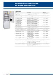
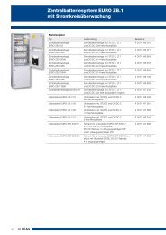
<strong>Central</strong> <strong>Battery</strong> <strong>System</strong> <strong>ZB</strong>-S<br />
<strong>with</strong> <strong>STAR</strong> <strong>Technology</strong><br />
Ordering information<br />
Type Scope of supply Order No.<br />
<strong>Central</strong> battery system <strong>Central</strong> battery system type <strong>ZB</strong>-S/26 4 0071 347 100<br />
<strong>ZB</strong>-S/26 incl. ST-S, LT.1 and DC/DC.2<br />
26 free module slots<br />
<strong>Central</strong> battery system <strong>Central</strong> battery system type <strong>ZB</strong>-S/18 4 0071 347 101<br />
<strong>ZB</strong>-S/18 incl. ST-S, LT.1 and DC/DC.2<br />
18 free module slots<br />
<strong>Central</strong> battery system <strong>Central</strong> battery system type <strong>ZB</strong>-S/10 C 4 0071 347 103<br />
<strong>ZB</strong>-S/10 C incl. ST-S, LT.1 and DC/DC.2<br />
10 free module slots<br />
<strong>Central</strong> battery system <strong>Central</strong> battery system type <strong>ZB</strong>-S/10 C6 4 0071 347 104<br />
<strong>ZB</strong>-S/10 C6 incl. ST-S, LT.1 and DC/DC.2<br />
10 free module slots<br />
<strong>Central</strong> battery system <strong>Central</strong> battery system type <strong>ZB</strong>-S/18 C3 4 0071 347 105<br />
<strong>ZB</strong>-S/18 C3 incl. ST-S, LT.1 and DC/DC.2<br />
18 free module slots<br />
<strong>Central</strong> battery system <strong>Central</strong> battery system type <strong>ZB</strong>-S/10 C3 4 0071 347 106<br />
<strong>ZB</strong>-S/10 C3 incl. ST-S, LT.1 and DC/DC.2<br />
10 free module slots<br />
<strong>Central</strong> battery system <strong>Central</strong> battery system type <strong>ZB</strong>-S/LAD 4 0071 347 102<br />
<strong>ZB</strong>-S/LAD incl. ST-S, LT.1 and DC/DC.2<br />
(2 free module slots possible)<br />
Substation US-S/36 Substation type US-S/36<br />
incl. ST-S and DC/DC.2<br />
36 free module slots<br />
4 0071 347 110<br />
Substation US-S/28 Substation type US-S/28<br />
incl. ST-S and DC/DC.2<br />
28 free module slots<br />
4 0071 347 111<br />
Substation US-S/21 Substation type US-S/21<br />
incl. ST-S and DC/DC.2<br />
21 free module slots<br />
4 0071 347 112<br />
Substation US-S/13 Substation type US-S/13<br />
incl. ST-S and DC/DC.2<br />
13 free module slots<br />
4 0071 347 113<br />
Substation US-S/5 Substation type US-S/5<br />
incl. ST-S and DC/DC.2<br />
5 free module slots<br />
4 0071 347 114<br />
Substation US-S/13 E30 Substation type US-S/13 E30<br />
incl. ST-S and DC/DC.2<br />
13 free module slots<br />
4 0071 347 115<br />
Substation US-S/9 E30 Substation type US-S/9 E30<br />
incl. ST-S and DC/DC.2<br />
9 free module slots<br />
4 0071 347 116<br />
Ordering information for accessories<br />
Type Order No.<br />
4 off DIN mounting rail incl. fixing accessories 4 0071 347 125<br />
3 off C-section rail incl. fixing accessories 4 0071 347 126<br />
200 mm plinth for <strong>ZB</strong>-S, depth 400 mm 4 0071 347 121<br />
100 mm plinth for <strong>ZB</strong>-S, depth 400 mm 4 0071 347 120<br />
200 mm plinth for <strong>ZB</strong>-S/18C3 and 10C3, depth 300 mm 4 0071 347 122<br />
3-piece baseplate for <strong>ZB</strong>-S, depth 400 mm, mouse-proof 4 0071 347 124<br />
Cable support rail 4 0071 347 123<br />
Metal flange plate for <strong>ZB</strong>-S battery cabinet, undrilled 4 0071 346 225<br />
Flange plate <strong>with</strong> foam rubber for <strong>ZB</strong>-S battery cabinet 4 0036 070 164<br />
Fireproof dowel M10 for E30 sub-distribution board,<br />
pack of 12, for installation in concrete walls<br />
4 0036 070 298<br />
Fireproof sealant, 310 ml cartridge,<br />
for sealing E30 fireproof trunking<br />
4 0036 070 297<br />
<strong>CEAG</strong> Notlichtsysteme GmbH 3/7<br />
3
Table of Covers<br />
Technical Data <strong>ZB</strong>-S<br />
Type <strong>ZB</strong>-S/26 <strong>ZB</strong>-S/18 <strong>ZB</strong>-S/LAD <strong>ZB</strong>-S/10 C <strong>ZB</strong>-S/10 C 6 <strong>ZB</strong>-S/18 C 3<br />
Rated voltage 400/230 V 400/230 V 400/230 V 230 V 230 V 230 V<br />
400/230 V 50 Hz 50 Hz 50 Hz 50 Hz 50 Hz 50 Hz 50 Hz<br />
Modules:<br />
Control module: ST-S 1 1 1 1 1 1<br />
DC/DC.2-converter 1 1 1 1 1 1<br />
Charging module 2.5 A 1 1 1 1 1 1<br />
Circuit module SKU CG-S 0-26 0-18 0-2 *2 0-10 0-10 0-18<br />
Charging booster 2.5 A 0-6 *1 0-6 *1 0-10 0-1 *3 0-2 *4 –<br />
Cabinet construction:<br />
Conductor size<br />
for mains and battery supply<br />
50 mm 2 50 mm 2 50 mm 2 16 mm 2 16 mm 2 16 mm 2<br />
Three-phase distribution yes yes yes no no no<br />
Conductor size 6 feeders, 6 feeders, 15 feeders, 1 feeder 1 feeder 1 feeder<br />
Outgoing circuits 16 mm 2 16 mm 2 16 mm 2 35 mm 2 35 mm 2 16 mm 2<br />
Max. conductor size<br />
Final circuit<br />
4 mm 2 4 mm 2 4 mm 2 4 mm 2 4 mm 2 4 mm 2<br />
Cable entry from top yes yes yes *7 yes yes yes<br />
Cable entry from bottom yes yes yes *7 no no no<br />
Enclosure class IP 21 IP 21 IP 21 IP 21 IP 21 IP 21<br />
Dimensions H x W x D (mm) 2050 x 2050 x 2050 x 2050 x 2050 x 1800 x<br />
800 x 400 800 x 400 800 x 400 800 x 400 800 x 600 600 x 300<br />
Base (optional) 100/200 100/200 100/200 200 – 200<br />
Lock 3 mm 3 mm 3 mm 3 mm 3 mm 3 mm<br />
two-way two-way two-way two-way two-way two-way<br />
<strong>Battery</strong> capacity,<br />
installed in:<br />
Compact cabinet – – – 5.5-52 Ah 5.5-80 Ah 5.5-24 Ah<br />
<strong>Battery</strong> cabinet 24-390 Ah *6 24-390 Ah *6 24-390 Ah *6 – – –<br />
<strong>Battery</strong> rack 24-390 Ah *6 24-390 Ah *6 24-390 Ah *6 – – –<br />
Other battery sizes on application<br />
*1 When 6 boosters are fitted, a double bus carrier is necessary.<br />
*2 Up to 8 boost chargers are possible when 2 SKU are fitted.<br />
*3 When 1 booster is fitted a single booster adapter is necessary.<br />
<strong>CEAG</strong> Notlichtsysteme GmbH 3/8
Table of Covers<br />
Technical Data <strong>ZB</strong>-S<br />
<strong>ZB</strong>-S/10 C3 US-S/36 US-S/28 US-S/21 US-S/13 US-S/5 US-S/13 E30<br />
230 V 400/230 V 400/230 V 230 V 230 V 230 V 230 V<br />
50 Hz 50 Hz 50 Hz 50 Hz 50 Hz 50 Hz 50 Hz<br />
1 1 1 1 1 1 1<br />
1 1-2 1-2 1 1 1 1<br />
1 – – – – – –<br />
0-10 0-36 *5 0-28 *5 0-21 0-13 0-5 0-13<br />
– – – – – – –<br />
16 mm 2 35 mm 2 35 mm 2 35 mm 2 16 mm 2 16 mm 2 16 mm 2<br />
no yes yes no no no no<br />
1 feeder – – – – – –<br />
16 mm 2<br />
4 mm 2 4 mm 2 4 mm 2 4 mm 2 4 mm 2 4 mm 2 4 mm 2<br />
yes yes yes yes yes yes yes<br />
no yes yes no no no no<br />
IP 21 IP 21 IP 21 IP 54 IP 54 IP 54 IP 41<br />
1800 x 2050 x 2050 x 1200 x 800 x 600 x<br />
600 x 300 800 x 400 800 x 400 600 x 300 600 x 250 400 x 250 –<br />
200 100/200 100/200 300 – – –<br />
3 mm 3 mm 3 mm 3 mm 3 mm 3 mm 3 mm<br />
two-way two-way two-way two-way two-way two-way two-way<br />
5.5-24 Ah – – – – – –<br />
– – – – – – –<br />
– – – – – – –<br />
*4 When 2 boosters are fitted a double booster adapter is necessary.<br />
*5 The DC/DC.2 converter can supply up to 26 SKU CG-S. A second DC/DC.2 converter for 27 SKU and more is necessary.<br />
*6 Higher battery capacities ≥ 130 Ah are achieved by connecting several battery sets in parallel.<br />
*7 Please indicate the cable entry when planning the system.<br />
<strong>CEAG</strong> Notlichtsysteme GmbH 3/9<br />
3
<strong>ZB</strong>-S<br />
<strong>System</strong> Components<br />
and Options<br />
■ Plug-in terminals for easy<br />
installation<br />
■ Later extension no problem<br />
■ Easily accessible fuses<br />
■ Quick-fixing devices for easy<br />
mounting<br />
For ease of installation, all modules are<br />
provided <strong>with</strong> plug-in terminals. Thereby,<br />
the modules can easily be replaced.<br />
All modules wired ready for connection to<br />
3-level isolating neutral terminals 4 mm 2 .<br />
The operating elements and displays as<br />
well as the fuses are easily accessible on<br />
the front of the modules.<br />
All modules are mounted by means of two<br />
quick-fixing devices so that their replacement<br />
is no problem at all. Care has to be<br />
taken that the removed modules are again<br />
fitted in the same place.<br />
<strong>CEAG</strong> Notlichtsysteme GmbH 3/10
<strong>ZB</strong>-S<br />
<strong>System</strong> Components<br />
and Options<br />
A freely programmable control module <strong>with</strong><br />
non-volatile program memory and 4-line<br />
alphanumeric display monitors and<br />
controls the central battery system. All<br />
functions such as charging, mains/<br />
emergency lighting selection and deep<br />
discharge protection of the devices and<br />
the emergency luminaires are tested<br />
automatically. Any faults that occur are<br />
signalled immediately. An interface enables<br />
a central monitoring facility to be<br />
connected. In the event of a short circuit or<br />
open circuit in current loops, differential<br />
monitors immediately power on the system<br />
(maintained light) or put the system in<br />
readiness.<br />
– Nonvolatile memory<br />
– Automatic luminaire search function<br />
– Individual luminaire monitoring<br />
– Automatic DLS/TLS search function<br />
– Selective manual reset/circuit<br />
– Selective emergency light/circuit<br />
– Password function<br />
– Final circuit fuse monitoring<br />
– Module-selective battery operation<br />
– Control module <strong>with</strong> multi-master-mode M3 Control module<br />
Sealed keypad <strong>with</strong> 3 keys for:<br />
– Test (mains failure - battery operation)<br />
– Function test start / cancel<br />
– Operating duration test start / cancel<br />
3 freely assignable function keys for:<br />
– <strong>System</strong> disable/enable<br />
– Manual reset<br />
– Cancel function test<br />
– Show fault list<br />
– Maintained light off/on<br />
– Power on complete safety lighting system<br />
(continuity lighting)<br />
– Mains failure simulation UV-A<br />
(emergency operation)<br />
– Reset deep discharge protection<br />
– Find insulation failure<br />
– Service Pin Message<br />
7 control keys<br />
for user-friendly navigation<br />
LED indicators for:<br />
– Mains<br />
– <strong>Battery</strong><br />
– Fault<br />
Display:<br />
4 x 20 characters, backlit, program<br />
adjustable contrast and brightness.<br />
Displays include:<br />
– Date/Time<br />
– Charging malfunction<br />
– Deep discharge protection<br />
– <strong>Battery</strong> voltage/charge current (+)<br />
– <strong>Battery</strong> discharge current in test or<br />
failure (-)<br />
– Manual reset<br />
– Test mode<br />
– Delay-time on mains return<br />
(remaining time in min.)<br />
– Luminaire failure <strong>with</strong> location label<br />
– Insulation fault <strong>with</strong> circuit indication<br />
– Failure mains sub DB (<strong>with</strong> location label)<br />
– Failure/programming information<br />
Connections:<br />
– Connection for disable switch:<br />
Control loops for blocking the installation<br />
during factory shutdowns <strong>with</strong> differential<br />
loop monitoring for short-circuit and<br />
open circuit detection.<br />
Differential monitoring: Short-circuit or<br />
open circuit result in readiness for<br />
operation of the system.<br />
– Connection for phase monitor:<br />
24V current loop for requesting<br />
emergency lighting using differential loop<br />
monitoring for the detection of shortcircuit<br />
and open circuits.<br />
Differential monitoring: Short-circuit or<br />
open circuit result in the immediate<br />
power on (maintained light) of the<br />
system.<br />
– Connection for floating signalling<br />
contacts and buzzer:<br />
3 floating relays, each 1x UM,<br />
24V 0.5A; buzzer<br />
One or more of 11 different signals can<br />
be assigned to each floating contact or<br />
to the buzzer. Freely programmable,<br />
DIN VDE 0108 requirement can be<br />
called at any time as a preset.<br />
– Connection for analog inputs:<br />
4 off freely assignable 24 V analog<br />
inputs, can be programmed negated<br />
and non negated, e.g. for start / cancel<br />
function test, start / cancel operating<br />
duration test, disable / enable system,<br />
manual reset, maintained light on / off,<br />
power on safety lighting as continuity<br />
lighting.<br />
<strong>CEAG</strong> Notlichtsysteme GmbH 3/11<br />
3
Programmable signalling contacts, each:<br />
1 x changer / 1 x 24 / 0 V and 0.5 A<br />
14 12<br />
11<br />
<strong>ZB</strong>-S<br />
<strong>System</strong> Components<br />
and Options<br />
Technical data<br />
Display 4 x 20 character display,<br />
program adjustable contrast<br />
Illumination backlighting, program adjustable brightness<br />
Keypad sealed, <strong>with</strong> 6 function and 7 control keys<br />
Readout <strong>Battery</strong> voltage<br />
<strong>Battery</strong> charge current (+)<br />
<strong>Battery</strong> discharge current in test or failure (-)<br />
Charge fault<br />
Luminaire failure <strong>with</strong> location label<br />
Deep discharge protection<br />
Manual reset<br />
Delay-time on mains return<br />
Failure mains sub DB (<strong>with</strong> location label)<br />
Test mode<br />
Date/Time<br />
Insulation fault <strong>with</strong> circuit label<br />
Failure information<br />
Programming information<br />
Status – Mains<br />
– <strong>Battery</strong><br />
– Controller<br />
Potential-free signal contacts, buzzer<br />
3 floating relays, each 1 x UM, 24 V 0.5 A; buzzer<br />
Freely programmable, VDE 0108 requirement can be called at any time as a preset.<br />
Status 11/12/14 21/22/24 31/32/33<br />
Group fault Ready <strong>Battery</strong> operation<br />
(Emerg operation)<br />
Mains operation – X –<br />
Mains failure – – X<br />
Mains failure S3-S4/LON – – X<br />
Charge failure X – –<br />
Converter failure X – –<br />
Luminaire failure X – –<br />
Group failure X – –<br />
Deep discharge protection X – –<br />
Insul. monitor X – –<br />
Function test – X X<br />
Operating duration test – X X<br />
Contact assignment<br />
11/14: N/C<br />
11/12: N/O<br />
21/24: N/C<br />
21/22: N/O<br />
31/34: N/C<br />
31/32: N/O<br />
X = active = 11/14 + 21/24 + 31/34 closed<br />
Ordering details<br />
Type Model Order No.<br />
Control module <strong>ZB</strong>-S compl. <strong>with</strong> SMC Plug-in module all devices 4 0071 347 050<br />
<strong>CEAG</strong> Notlichtsysteme GmbH 3/12
8-MB-SMC<br />
<strong>ZB</strong>-S<br />
<strong>System</strong> Components<br />
and Options<br />
Smart Media Card<br />
Flexible data storage <strong>with</strong> 8 MB capacity for<br />
system and log book configuration, e.g. of the<br />
mandatory archiving of log book information<br />
for a minimum of 2 years.<br />
The system can also be programmed at any PC<br />
using optional floppy disk adapter and <strong>CEAG</strong><br />
software. Texts can also be entered on the<br />
control module in the switch cabinet.<br />
Ordering details<br />
Type Model Order No.<br />
Smart media card Smart media card formatted for <strong>ZB</strong>-S 4 0071 347 153<br />
Adapter 3,5“ Floppy disk adapter for smart media card 4 0064 079 894<br />
Software Software for external programming<br />
of the <strong>ZB</strong>-S via PC 4 0071 347 152<br />
Basic information about the SMC<br />
(Smart Media Card)<br />
Removable configuration and<br />
log book storage<br />
SMC<br />
PC <strong>with</strong> <strong>CEAG</strong> software<br />
for SMC programming and<br />
analysis<br />
Storage of:<br />
● 360.000 log book entries<br />
● Location texts for the luminaires<br />
(20 characters per luminaire)<br />
● Location texts of external modules<br />
such as phase monitor, DLS, TLS<br />
(20 characters per module)<br />
● Circuit names<br />
(20 characters per circuit)<br />
● <strong>System</strong> name (20 characters)<br />
<strong>CEAG</strong> Notlichtsysteme GmbH 3/13<br />
3<br />
Programming<br />
– Easy system programming on an office<br />
PC from installation plans<br />
– <strong>System</strong> configuration can be stored in the PC
DC-DC converter.2<br />
Charging modul LT.1 2,5 A<br />
<strong>ZB</strong>-S<br />
<strong>System</strong> Components<br />
and Options<br />
DC/DC Converter.2<br />
The DC/DC converter.2 converts the 220 V DC<br />
battery voltage to 24 V DC and 6 V DC<br />
to supply the modules and processor.<br />
Technical data<br />
Fusing 2 AT/250 V, 6.3 x 32<br />
24 V external 20 W continuous rating<br />
Outgoing circuit <strong>with</strong> front panel connector<br />
Isolated voltage<br />
24 V internal 100 W continuous rating<br />
140 W peak rating (20 ms)<br />
Supplies max. 26 SKUs<br />
Ordering details<br />
Type Order No.<br />
DC/DC converter.2 4 0071 347 071<br />
Charging module LT.1 2,5 A<br />
The charging section is used to recharge 220 V<br />
batteries. The charging current is 2,5 A.<br />
Additional boost chargers <strong>with</strong> a charging current<br />
of 2,5 A are used for higher battery ratings.<br />
The boosters are driven by the LT.1 2,5 A.<br />
Signals such as failure, insulation fault and boost<br />
charging can be transmitted <strong>with</strong> the charger's<br />
Technical data<br />
Charging characteristic IU<br />
Terminals 2.5 mm2 rigid and flexible<br />
Mains fuse 6,3 AT/250 V/5 x 20<br />
<strong>Battery</strong> fuse 3,15 AT/250 V/5 x 20<br />
End-of-charge voltage<br />
Boost charge<br />
Trickle charge<br />
248 V DC<br />
240 V DC<br />
Max. charging current<br />
Charg. mod. LT 2.5<br />
Booster<br />
2.5 A<br />
2.5 A<br />
Deep discharge protection 183.6 V DC<br />
Floating signalling contacts<br />
11, 12, 21, 22, 31, 32<br />
0.5 A/24 V AC DC<br />
Ordering details<br />
A number of converters can be connected in<br />
parallel 6 V internal:<br />
– Supplies 26 SKUs CG-S 2 x 3 A<br />
– Incoming supply can be run via AC/AC<br />
– Rectifier in the DC/DC converter for AC supply<br />
floating signalling contacts. A display on the<br />
actual device indicates the current battery<br />
capacity (Capacity > 10 %, > 50 %, 100 %).<br />
The built-in insulation monitor reports an<br />
insulation fault between battery + and PE or<br />
battery – and PE.<br />
Type Scope of supply Order No.<br />
LT.1 2,5 A Plug-in module 4 0071 346 555<br />
Boost charger 2,5 Separate module 4 0071 346 345<br />
<strong>CEAG</strong> Notlichtsysteme GmbH 3/14
SKU CG-S 2 x 3 A<br />
SKU CG-S 1 x 6 A<br />
<strong>ZB</strong>-S<br />
<strong>System</strong> Components<br />
and Options<br />
SKU CG-S 2 x 3 A<br />
Hybrid operation of maintained light, nonmaintained<br />
light and switched maintained light<br />
in a single circuit can be programmed <strong>with</strong> no<br />
additional data cable.<br />
– Up to 20 luminaires can be monitored<br />
individually<br />
– Individual selection per AC/DC circuit<br />
– Separate fusing for mains and battery<br />
operation<br />
Technical data<br />
Fusing 5 AT/250 V, 6.3 x 32<br />
Continuous current rating 3 A per circuit<br />
Max. inrush current 250 A/ms per circuit<br />
Typical switch over time AC/DC approx. 200 ms<br />
Ordering details<br />
Type Scope of supply Order No.<br />
SKU Circuit changer SKU CG-S 2 x 3 A 4 0071 347 051<br />
SKU CG-S 1 x 6 A<br />
Hybrid operation of maintained light, nonmaintained<br />
light and switched maintained light<br />
in a single circuit can be programmed <strong>with</strong> no<br />
additional data cable.<br />
– Up to 20 luminaires can be monitored<br />
individually<br />
– Separate fusing for mains and battery<br />
operation<br />
Technical data<br />
Fusing 10 AT/250 V, 6.3 x 32<br />
Continuous current rating 6 A<br />
Max. inrush current 250 A/ms<br />
Typical switch over time AC/DC approx. 200 ms<br />
Ordering details<br />
– When there is a phase-to-ground fault in AC<br />
operation, fault-free DC operation can continue<br />
– Easy access to fuses<br />
– LED indicates fault and Run/ON for each<br />
circuit<br />
– Supplies ballast luminaires and incandescent<br />
lamps<br />
– Service-friendly modular units are wired up<br />
and ready to connect to 3-tier disonnect<br />
neutral terminals 4 mm 2<br />
Type Scope of supply Order No.<br />
SKU Circuit changer SKU CG-S 1 x 6 A 4 0071 347 345<br />
Light switch for luminaire 3<br />
Non-maintained light<br />
Maintained light<br />
Switched<br />
maintained light<br />
Operation of the <strong>STAR</strong> <strong>Technology</strong><br />
– When there is a phase-to-ground fault in AC<br />
operation, fault-free DC operation can continue<br />
– Easy access to fuses<br />
– LED indicates fault and Run/ON for each<br />
circuit<br />
– Supplies ballast luminaires and incandescent<br />
lamps<br />
– Service-friendly modular units are wired up<br />
and ready to connect to 3-tier disconnect<br />
neutral terminals 4 mm 2<br />
<strong>CEAG</strong> Notlichtsysteme GmbH 3/15<br />
3
SKU CG 2 x 3 A<br />
SKU CG 1 x 6 A<br />
<strong>ZB</strong>-S<br />
<strong>System</strong> Components<br />
and Options<br />
SKU CG 2 x 3 A<br />
Change-over module SKU,<br />
module <strong>with</strong>out S-Function<br />
– Up to 20 luminaires can be monitored<br />
individually<br />
– Individual selection per AC/DC circuit<br />
– Separate fusing for mains and battery<br />
operation<br />
– When there is a phase-to-ground fault in AC<br />
operation, fault-free DC operation can continue<br />
Technical data<br />
Fusing 5 AT/250 V, 6.3 x 32<br />
Continuous current rating 3 A per circuit<br />
Max. inrush current 120 A/ms per circuit<br />
Typical switch over time AC/DC approx. 200 ms<br />
Ordering details<br />
Type Scope of supply Order No.<br />
SKU Circuit changer SKU CG 2 x 3 A 4 0071 347 290<br />
SKU CG 1 x 6 A<br />
Change-over module SKU,<br />
module <strong>with</strong>out S-Function<br />
– Up to 20 luminaires can be monitored<br />
individually<br />
– Individual selection per AC/DC circuit<br />
– Separate fusing for mains and battery<br />
operation<br />
Technical data<br />
Fusing 10 AT/250 V, 6.3 x 32<br />
Continuous current rating 6 A<br />
Max. inrush current 180 A/ms<br />
Typical switch over time AC/DC approx. 200 ms<br />
Ordering details<br />
– Easy access to fuses<br />
– LED indicates fault and Run/ON for each<br />
circuit<br />
– Supplies ballast luminaires and incandescent<br />
lamps<br />
– Service-friendly modular units are wired up<br />
and ready to connect to 3-tier disconnect<br />
neutral terminals 4 mm 2<br />
– When there is a phase-to-ground fault in AC<br />
operation, fault-free DC operation can continue<br />
– LED indicates fault and Run/ON<br />
– Supplies ballast luminaires and incandescent<br />
lamps<br />
– Service-friendly modular units are wired up<br />
and ready to connect to 3-tier disconnect<br />
neutral terminals 4 mm 2<br />
Type Scope of supply Order No.<br />
SKU Circuit changer SKU CG 1 x 6 A 4 0071 347 346<br />
<strong>CEAG</strong> Notlichtsysteme GmbH 3/16
Printer PD 3<br />
CG IV relay module<br />
<strong>ZB</strong>-S<br />
<strong>System</strong> Components<br />
and Options<br />
Printer PD 3<br />
The printer logs and memorizes all function<br />
tests and mains failures of a <strong>ZB</strong>-S cover or a<br />
substation.<br />
After the performance of an automatic function<br />
test, the results are printed out in plain text<br />
stating also the time and date. The printing is<br />
made automatic by each entry into the log book<br />
of the control module. A mains failure is also<br />
logged <strong>with</strong> time and date.<br />
Technical data<br />
Printer paper woodfree printing paper<br />
Paper width 57.5 mm<br />
Max. dia. of the paper rol 61 mm<br />
Core hole dia. 12 mm<br />
Ordering details<br />
Type Scope of supply Order No.<br />
PD 3 Plug-in module 4 0071 347 316<br />
Spare part 1 roll printer paper 4 0078 079 666<br />
Spare part packet 1 inle ribbon and 1 roll printer paper 4 0071 346 042<br />
CG IV relay module<br />
The bipolar CG IV relay module transmits data<br />
and operational states of the covers/substations<br />
Technical data<br />
Terminals/plug-in terminals 2.5 mm 2 rigid and flexible<br />
Switching capacity of the contacts 24 V/0.5 A AC DC<br />
Ordering details<br />
to a central building management system.<br />
Type Scope of supply Order No.<br />
CG IV Plug-in module 4 0071 343 971<br />
ZLT<br />
Function test On/Off<br />
Emergency operation<br />
Mains operation<br />
Emergency light failure<br />
Charging fault<br />
Deep discharge protection<br />
Duration test On/Off<br />
The printer documents the operational state of<br />
emergency luminaires of a emergency lighting<br />
supply system.<br />
By means of the printer, the maintenance cost of<br />
an emergency lighting system can be reduced,<br />
since information on possible failures of the<br />
luminaires (e. g. defective lamp) is printed out in<br />
detail.<br />
CG IV<br />
<strong>CEAG</strong> Notlichtsysteme GmbH 3/17<br />
3
1 2 3<br />
Mains distribution board<br />
Mains distribution module D02-E18<br />
1 2 3<br />
<strong>Battery</strong> distribution board<br />
<strong>Battery</strong> distribution module D02-E18<br />
<strong>ZB</strong>-S<br />
<strong>System</strong> Components<br />
and Options<br />
Mains distribution board<br />
The mains supply to a <strong>ZB</strong>-S/26 or <strong>ZB</strong>-S/18<br />
system comes via a modular mains distribution<br />
board. This includes a size 00C load disconnector<br />
(1) <strong>with</strong> a maximum conductor size<br />
of 50 mm 2 (torque rating 3 Nm) and allows the<br />
connection of up to 6 slave stations to modular<br />
size D02-E18 outgoing mains circuits (2) <strong>with</strong> the<br />
necessary terminals for neutral and ground (3).<br />
Technical data<br />
Current rating 63 A<br />
Rated operating voltage 400 V<br />
Box terminal for circular conductor up to 16 mm 2<br />
Material Polyamide (PA 6.6), 30 % glass-fibre-reinforced<br />
Scope of supply includes 3 screw caps E18 and<br />
3 x 25 A D02 fuse-links<br />
Ordering details<br />
The same mains distribution boards must also be<br />
used three-phase for feeders to powerful slavestations<br />
(accommodates up to 2 slave stations in<br />
this case). The components are simply plugged<br />
on from the front and securely contacted. The<br />
mains power supplies for the smaller systems are<br />
assembled in the conventional way.<br />
Type Scope of supply Order No.<br />
Mains distribution module includes 3 screw caps E18 and<br />
for busbar mounting 3 x 25 A D02 fuse-links 4 0071 347 160<br />
<strong>Battery</strong> distribution board<br />
The battery supply to a <strong>ZB</strong>-S/26 or <strong>ZB</strong>-S/18<br />
system comes via a modular battery distribution<br />
board. This includes a size 00C load<br />
disconnector (1) <strong>with</strong> a maximum conductor size<br />
of 50 mm 2 (torque rating 3 Nm) and allows the<br />
connection of up to 6 slave stations to modular<br />
Technical data<br />
Current rating 63 A<br />
Rated operating voltage 400 V<br />
Box terminal for circular conductor up to 16 mm 2<br />
Material Polyamide (PA 6.6), 30 % glass-fibre-reinforced<br />
Scope of supply includes 2 screw caps E18 and<br />
2 x 25 A D02 fuse-links<br />
Ordering details<br />
size D02-E18 outgoing battery circuits (2) <strong>with</strong><br />
related terminals for ground (3). The components<br />
are simply plugged on from the front and<br />
securely contacted. The battery power supplies<br />
for the smaller systems are assembled in the<br />
conventional way.<br />
Type Scope of supply Order No.<br />
<strong>Battery</strong> distribution module includes 2 screw caps E18 and<br />
for busbar mounting 2 x 25 A D02 fuse-links 4 0071 347 161<br />
Technical data<br />
Busbar guard<br />
Cover strip for clip-mounting to the Ready cut to module width<br />
trunking section<br />
Material Hard PVC<br />
Ordering details<br />
Type Scope of supply Order No.<br />
Busbar cover strip Cover strip in module width for clip<br />
mounting to the trunking section 4 0071 347 162<br />
<strong>CEAG</strong> Notlichtsysteme GmbH 3/18
Boost charger 2.5 A<br />
Booster rack, 4-way<br />
Booster rack, 2-way<br />
Booster rack, single, compact<br />
<strong>ZB</strong>-S<br />
<strong>System</strong> Components<br />
and Options<br />
Charging booster<br />
As well as the charging module of the <strong>ZB</strong>-S<br />
<strong>Central</strong> <strong>Battery</strong> <strong>System</strong>, boost chargers must be<br />
individually installed to achieve the battery<br />
recharge time required by statute for configured<br />
battery sets.<br />
The number of additional boosters that are<br />
required for your configuration will be found in<br />
Tables 4 (to VDE 0108) and 4a (to DIN EN<br />
50171) on page 30 of this catalogue.<br />
Technical data<br />
Charge current 2.5 A<br />
The booster must be used in conjunction <strong>with</strong> the LT.1 charger (4 0071 346 555)<br />
The booster cuts in when boost charging is active and the charging voltage is < 247 V<br />
Ordering details<br />
Type Scope of supply Order No.<br />
Boost charger new Boost charger 2.5 A<br />
(only in conjunction <strong>with</strong> LT.1 charger<br />
Order No. 4 0071 346 555) 4 0071 346 345<br />
Booster rack<br />
A 4-way booster rack <strong>with</strong> 3-phase supply<br />
is mounted in system types <strong>ZB</strong>-S/26 and<br />
<strong>ZB</strong>-S/18. It is for supplying the 2.5 A boost<br />
chargers only!<br />
Technical data<br />
Supply voltage 400 V AC/220 V DC<br />
3-phase split slots<br />
Conductor size 4 mm 2 max.<br />
Ordering details<br />
The optional 2-way booster rack can be used to<br />
expand the system to 6 slots.<br />
Type Scope of supply Order No.<br />
Booster rack, 4-way Unit accommodates 4 x 2.5 A boost chargers<br />
for <strong>ZB</strong>-S/26 and <strong>ZB</strong>-S/18 4 0071 347 043<br />
Booster rack, 2-way Unit accommodates 2 extra<br />
2.5 A boost chargers for <strong>ZB</strong>-S/26 and <strong>ZB</strong>-S/18<br />
(only in conjunction <strong>with</strong> 4 0071 347 043) 4 0071 347 130<br />
Booster rack, compact<br />
The compact version of the booster rack is<br />
intended for use in <strong>ZB</strong>-S compact systems. The<br />
single and double compact booster racks have<br />
Technical data<br />
Supply voltage 230 V AC/220 V DC<br />
Conductor size 2.5 mm 2 max.<br />
Ordering details<br />
been designed for system types <strong>ZB</strong>-S/10 C and<br />
<strong>ZB</strong>-S/10 C6 respectively. They are for supplying<br />
the 2.5 A boost chargers only!<br />
Type Scope of supply Order No.<br />
Booster rack, single Unit accommodates 1 x 2.5 A boost charger<br />
compact for <strong>ZB</strong>-S/10 C 4 0071 347 167<br />
Booster rack, double Unit accommodates 2 x 2.5 A boost chargers<br />
compact for <strong>ZB</strong>-S/10 C6 4 0071 347 130<br />
<strong>CEAG</strong> Notlichtsysteme GmbH 3/19<br />
3
L1<br />
L2<br />
L3<br />
N<br />
UV-AV1<br />
Resistor<br />
1 kΩ<br />
3PH<br />
1 2 3 S/S<br />
L1<br />
L2<br />
L3<br />
N<br />
Three-phase monitor<br />
UV-AV2<br />
3PH<br />
1 2 3 S/S<br />
<strong>ZB</strong>-S<br />
<strong>System</strong> Components<br />
and Options<br />
Connection terminals<br />
Terminals up to 4 mm 2 rigid or flexible are<br />
provided for connecting the external phase<br />
monitors, monitoring equipment and control<br />
units.<br />
Current loop<br />
S3/S4<br />
Differential monitoring: A short or open circuit causes the system to energise<br />
immediately (maintained light).<br />
Phase monitor switch<br />
closed (1 kΩ): Normal system mode<br />
Three-phase monitor<br />
Technical data<br />
Dimensions (mm) (h x w x d) 85 x 52,5 x 65<br />
Enclosure Plastic<br />
Terminals 2.5 mm 2 rigid and flexible<br />
Type of mounting DIN rail<br />
Contact 1, 2, 3, S, S 0.5 A/24 V AC/DC<br />
Ordering details<br />
<strong>ZB</strong>-S<br />
When one phase fails, the module switches<br />
a relay contact and interrupts the standard<br />
electronic 24 V current loop in the <strong>ZB</strong>-S cover<br />
and/or the US-S substations.<br />
Terminals up to 4 mm 2 on DIN rail for rigid or<br />
flexible cables are provided for connecting the<br />
final circuits.<br />
The terminals are designed as 3-level neutral<br />
disconnect terminal.<br />
24 V current loop for emergency lighting request<br />
using differential loop monitoring for shortcircuit<br />
and open circuit detection.<br />
The emergency luminaires in non-maintained<br />
mode are switched to mains operation, if the<br />
mains voltage still applies to the <strong>ZB</strong>-S cover<br />
(MDB).<br />
Type Scope of supply Order No.<br />
Three-phase monitor Module ready for mounting 4 0071 343 430<br />
<strong>CEAG</strong> Notlichtsysteme GmbH 3/20
Mains operation<br />
<strong>Battery</strong> operation<br />
Sum failure<br />
Remote switch<br />
F3 remote indication<br />
–<br />
12<br />
22<br />
32<br />
S1<br />
S2<br />
+<br />
1k<br />
<strong>ZB</strong>-S<br />
<strong>System</strong> Components<br />
and Options<br />
Remote switch<br />
S1 S2 11 12 14 21 22 24 31 32 34 + –<br />
Terminal strip X1.1 24 V out<br />
S1/S2 Control loop for blocking<br />
the installation during factory<br />
shutdowns<br />
<strong>ZB</strong>-S<br />
Differential monitoring: A short-circuit or open circuit causes the system to be enabled.<br />
F3 switch closed: <strong>System</strong> ready<br />
F3 switch open (1 kΩ): <strong>System</strong> blocked<br />
F3 remote indication<br />
F3 remote indication flush-mounted<br />
AC Module<br />
F3 remote indication<br />
Operating from a battery supply, the F3 remote<br />
indication ensures the display of important<br />
operational information also in a mains fail<br />
condition. By means of the built-in key-operated<br />
switch, the connected <strong>ZB</strong>/US-S systems can be<br />
Control loop for blocking the installation during<br />
factory shutdowns <strong>with</strong> differential loop<br />
monitoring for short-circuit and open circuit<br />
detection.<br />
Technical data<br />
Terminals surface-mounted 2.5 mm 2 rigid and flexible<br />
Dimensions (mm) (h x w x d) 160 x 80 x 55<br />
Terminals flush-mounted 1.5 mm 2 rigid and 1 mm 2 flexible<br />
Dimensions (mm) (h x w x d) 80 x 80 x 55<br />
Ordering details<br />
centrally put out of operation. Thereby, the<br />
F3 remote indication complies <strong>with</strong> DIN VDE<br />
0108 part 1, para. 6.4.3.11 which permits a<br />
remote control only if the operation by unauthorized<br />
persons is prevented.<br />
Type Scope of supply Order No.<br />
F3 remote indication Module 4 0071 338 497<br />
F3-remote indication Performance for installation in the<br />
flush-mounted flush-mounted switch receptively empty<br />
space box acc. DIN VDE 0606 4 0071 347 490<br />
AC Module<br />
Together <strong>with</strong> the DC/DC converter.2, the<br />
optional AC module supplies the internal system<br />
Technical data<br />
Constructed to EN 61558/VDE 570<br />
Rated voltage 230 V 50 Hz<br />
Nominal power 240 VA<br />
Fusing 1.6 A<br />
Ordering details<br />
voltage when the battery supply is isolated,<br />
e.g. for maintenance.<br />
Type Scope of supply Order No.<br />
AC Module External transformer module AC/AC converter<br />
240 VA incl. fitting adapter 4 0071 347 162<br />
<strong>CEAG</strong> Notlichtsysteme GmbH 3/21<br />
3
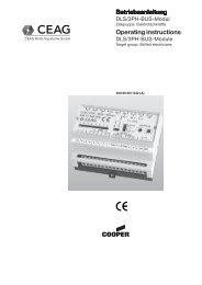
<strong>ZB</strong>-S<br />
<strong>System</strong> Components<br />
and Options<br />
External DLS/3Ph-Bus-Module<br />
The DLS/3PH bus module can be used as a<br />
phase monitor and for light switch polling for the<br />
common switching of safety and general lighting<br />
systems. The housing is suitable for DIN rail<br />
mounting.<br />
Technical data<br />
Device supply 24 V DC (min. 19 V, max. 30 V)<br />
Power consumption (all 8 channels connected) 20 mA ± 5 mA<br />
Degree of protection IP 20<br />
Insulation class I<br />
Ambient temperature -10 ° to + 40 °C<br />
Input channels 8 (optionally isolated) UN = 230 V<br />
DLS (channel 1-8) > 195 V -> ON < 138 V -> OFF<br />
3PH (channel 6-8) > 195 V -> ON < 138 V -> OFF<br />
Light switch inputs 8 off <strong>with</strong> LED display, or<br />
5 off <strong>with</strong> 3-phase monitor (selector)<br />
Monitoring threshold 60 - 85 % UNom (meets DIN EN 60598-2-22)<br />
Data bus RS 485<br />
Address range 1-25<br />
Weight 0.2 kg<br />
Dimensions (l x w x h) mm 105 x 85 x 60<br />
Mounting DIN rail<br />
Supply terminals/plug-on terminals 2.5 mm 2 rigid and flexible<br />
Ordering details<br />
The module has a service button, an RS 485<br />
bus port (integral 120 Ohm bus load resistor)<br />
<strong>with</strong> 24 V module supply, and is addressed <strong>with</strong><br />
encoding switches. Coloured LEDs indicate<br />
fault, ON status and operation.<br />
Type Scope of supply Order No.<br />
DLS/3Ph-Bus-Module Module for DIN rail mounting 4 0071 346 955<br />
DLS/3Ph-Bus-Module Module for DIN rail mounting<br />
inverse <strong>with</strong> inverse switching logic 4 0071 347 455<br />
DIN rails 4 off DIN rails for mounting<br />
external modules in the switch cabinet<br />
incl. fixing accessories 4 0071 347 125<br />
General lighting<br />
Safety lighting<br />
<strong>CEAG</strong> Notlichtsysteme GmbH 3/22
<strong>ZB</strong>-S<br />
<strong>System</strong> Components<br />
and Options<br />
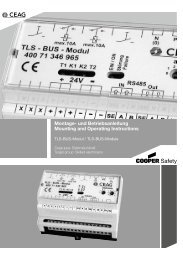
External TLS-Bus-Module<br />
The TLS bus module is used to poll stairwell<br />
light switches, to supply the glow lamps in<br />
mains and emergency operation and for the<br />
common switching of safety and general<br />
lighting. The housing is suitable for DIN rail<br />
mounting.<br />
The module has a service button, an RS 485<br />
bus port (integral 120 Ohm bus load resistor),<br />
Technical data<br />
Device supply 24 V DC (min. 19 V, max. 30 V)<br />
Power consumption at 24 V Standby 10 mA ± 3 mA<br />
1 button pushed 35 mA ± 5 mA<br />
2 buttons pushed 60 mA ± 6 mA<br />
Degree of protection IP 20<br />
Insulation class I<br />
Ambient temperature -10 °C to + 40 °C<br />
Connection T1/T2 max. 50 mA each<br />
e.g. 50 pushbuttons <strong>with</strong> 1 mA glow lamp<br />
Connection K1/K2 10 A/250 V AC<br />
Making current max. 120 A/ms<br />
Data bus RS 485<br />
Address range 1-25<br />
Weight 0.2 kg<br />
Dimensions (l x w x h) mm 105 x 85 x 60<br />
Mounting DIN rail<br />
Supply terminals/plug-in terminals 2.5 mm 2 rigid and flexible<br />
Number of IPB inputs 2 off incl. glow lamp supply<br />
(max. 50 mA)<br />
Load circuits for general lighting 2 off (10 A/120 A/ms)<br />
Variable On-time 1 to 15 min.<br />
Ordering details<br />
Type Scope of supply Order No.<br />
TLS-Bus-Module Module for DIN rail mounting 4 0071 346 965<br />
DIN rails 4 off DIN rails for mounting<br />
external modules in the switch cabinet<br />
incl. fixing accessories 4 0071 347 125<br />
Safety lighting<br />
Light IPB<br />
24 V module supply, and generates the glow<br />
lamp voltage. It also has a glow lamp flash<br />
function (30 s before On-time timeout). The<br />
TLS bus module is addressed <strong>with</strong> encoding<br />
switches. Coloured LEDs indicate fault, ON<br />
status and operation.<br />
General lighting<br />
<strong>CEAG</strong> Notlichtsysteme GmbH 3/23<br />
3
CG-S Bus<br />
max. length of bus 900 m<br />
extension via Router/Repeater<br />
CG-S RS485<br />
<strong>ZB</strong>-S<br />
terminal<br />
resistance<br />
120 Ω<br />
terminal<br />
resistance<br />
105 Ω<br />
RS 485<br />
max. length of bus 1200 m<br />
TLS<br />
DLS<br />
Electronic ballast/<br />
Luminaire control<br />
via cable of the<br />
final circuit.<br />
RS 485 Bus<br />
TLS<br />
CG-S Bus<br />
US-S2<br />
DLS<br />
max. length<br />
of bus 1200 m<br />
<strong>with</strong> JY(ST)Y<br />
4 x 2 x 0.8 mm<br />
US-S1<br />
max. length<br />
of bus 900 m<br />
<strong>with</strong> JY(ST)Y<br />
4 x 2 x 0.8 mm<br />
<strong>ZB</strong>-S<br />
<strong>ZB</strong>-S<br />
i<br />
<strong>ZB</strong>-S<br />
Bus technology<br />
Bus technology according to RS 485<br />
An RS 485 bus is used for data communication<br />
<strong>with</strong> external bus modules (DLS/3PH or TLS).<br />
CG-S RS485<br />
US-S<br />
RS 485<br />
max. length of bus 1200 m<br />
TLS<br />
max. 25 Busparticipants<br />
CG-<br />
Controller<br />
<strong>ZB</strong>-S<br />
TLS<br />
DLS<br />
Electronic ballast/<br />
Luminaire control<br />
via cable of the<br />
final circuit.<br />
DLS<br />
US-S3<br />
CG-Controller<br />
CG Vision<br />
GLT/BMS<br />
terminal<br />
resistance<br />
120 Ω<br />
terminal<br />
resistance<br />
105 Ω<br />
A connection to a central building services<br />
management system (BMS) can be made <strong>with</strong><br />
the CG-S bus.<br />
An isolated 24V/0.5 A power supply (SELV) is<br />
available for the external modules. The<br />
maximum line length depends on the required<br />
power and the conductor size.<br />
Overall structure of the bus system for<br />
communication <strong>with</strong> external switching modules<br />
and master control system<br />
RS485 bus for communication <strong>with</strong> external<br />
CG-S modules (DLS/3PH or TLS bus module).<br />
The terminating resistor (120 Ω, 0.5 W) can be<br />
connected in the modules.<br />
The <strong>ZB</strong>-S control cabinet also includes a<br />
resistor. This must be mounted in the <strong>ZB</strong>-S<br />
system if only one cable is laid.<br />
CG-S bus for communication by <strong>ZB</strong>-S or US-S<br />
systems <strong>with</strong> a CG controller <strong>ZB</strong>-S<br />
Notes:<br />
Bus topology: linear, double terminated (no spur lines allowed)<br />
The absolutely essential terminating resistors are supplied in a plastic pack in the control cabinet.<br />
Cable type (minimum requirement): JY(ST)Y 4 x 2 x 0.8 mm (twisted pair, screened)<br />
The conductor size required for the 24 V bus voltage will depend on the line length and the number<br />
of bus modules (Umin = 19 V DC)<br />
DLS = external maintained light switching module (DLS/3PH bus module)<br />
TLS = external stairwell light switching module<br />
BMS = Building Management <strong>System</strong><br />
<strong>CEAG</strong> Notlichtsysteme GmbH 3/24
CG-controller <strong>ZB</strong>-S<br />
8 MB Smart Media Card<br />
<strong>ZB</strong>-S<br />
CG-Controller<br />
CG-Controller <strong>ZB</strong>-S<br />
For the central monitoring of <strong>ZB</strong>-S, the novel<br />
<strong>CEAG</strong> CG-Controller offers a variety of new<br />
features:<br />
❒ Housing: degree of protection IP 65<br />
❒ Control and monitoring of up to<br />
32 emergency supply systems<br />
❒ 8 MB memory card for the storage of<br />
systems configuration, luminaire designation<br />
and log book<br />
❒ Programming of the CG-Controller<br />
via PC preprogrammed memory card<br />
via 8 MB SMC can be realized using a<br />
3,5¨ adapter disk<br />
Technical data<br />
Dimensions (mm) (H x W x D) 184 x 240 x 112<br />
Enclosure Plastic RAL 7035, <strong>with</strong> clear cover<br />
Degree of protection (IEC 529) IP 65<br />
Supply voltage 230 V 50/60 Hz/24 V DC<br />
Insulation class II<br />
Ambient temperature -5 °C to + 40 °C<br />
Connection terminals/plug-in terminals 2.5 mm2 rigid and flexible<br />
Display<br />
Illuminated, alphanumeric<br />
4 x 20 characters<br />
Keyboard membrane keypad 4 x 4<br />
Volt-free contact 1 x UM, 24 V 0.5 A; freely programmable<br />
Ordering details<br />
Type Supply source Order No.<br />
CG-Controller <strong>ZB</strong>-S Controller in enclosure incl. CG-S BUS-interface 4 0071 347 135<br />
Storage card Storage card reader,<br />
interface (SMC) ready for mounting CG-Controller <strong>ZB</strong>-S 4 0071 346 474<br />
Storage card SMC Storage card, 8 MB, 3.3 V<br />
formated for CG-Controller <strong>ZB</strong>-S 4 0071 347 145<br />
Adapter 3.5¨ Floppy disk adapter for smart media card 4 0064 079 894<br />
CG-S BUS Router for CG-S BUS for<br />
component DIN rail mounting 4 0071 347 142<br />
CG-S BUS Repeater for CG-S BUS for<br />
component DIN rail mounting 4 0071 347 143<br />
Software PC software for <strong>ZB</strong>-S, for alternative<br />
programming of the system configuration<br />
on PC. For Windows 95 and higher 4 0071 347 152<br />
CG Vision<br />
Fully automatic visual display, monitoring and<br />
programming software for standard PCs <strong>with</strong><br />
Windows 2000 or Windows XP Professional<br />
operating system, allows retrieval of<br />
detailed system-information about CG-S Bus<br />
technology at any time <strong>with</strong> just one bus line.<br />
Simple menu-assisted operation <strong>with</strong> short-info<br />
display. The CG-S Bus technology provides a<br />
continuous presence of the current operating<br />
status of all connected systems, <strong>with</strong> a<br />
continuous display of the last 5 events.<br />
Special features:<br />
● Up to 480 emergency lighting devices can<br />
be monitored and programmed<br />
● Emergency luminaires can be turned off in<br />
CG Vision via <strong>STAR</strong> technology<br />
❒ log book acc. to VDE 0108/10.89: Storage<br />
of results of funcitonal tests carried out for a<br />
period of 2 years<br />
❒ Storage of luminaire designation for<br />
6400 luminaires <strong>with</strong> 20 digits<br />
❒ Volt-free contact freely<br />
programmable for:<br />
● charging fault<br />
● luminaire fault<br />
● ISO failure<br />
● power failure or<br />
● battery operation<br />
● Programmable external LON switches on<br />
circuits<br />
● User can enter his own texts, e.g. for location<br />
labelling<br />
● Localised fault messages for each emergency<br />
light circuit and safety/exit luminaires,<br />
giving location in plain text.<br />
● Continuously updated information about<br />
charger and battery<br />
● Storage and retrieval of all log book data over<br />
a period of at least 2 years<br />
● Additional data storage on external magnetic<br />
media is possible at any time<br />
● User-programmable function and duration<br />
test<br />
<strong>CEAG</strong> Notlichtsysteme GmbH 3/25<br />
3
Main distribution board general lighting<br />
Visual display, monitoring and<br />
programming software<br />
Control and<br />
programming unit<br />
CG Controller<br />
<strong>ZB</strong>-S<br />
F3<br />
remote indicator<br />
R<br />
1)<br />
1) Operation CG-Controller<br />
<strong>ZB</strong>-S in combination <strong>with</strong><br />
CG Vision only in observer<br />
mode possible<br />
CG-S BUS<br />
7<br />
3<br />
2<br />
<strong>ZB</strong>-S<br />
Installation Example<br />
3<br />
ST-S<br />
3 (5)<br />
<strong>Central</strong> <strong>Battery</strong> <strong>System</strong> <strong>ZB</strong>-S<br />
3<br />
DLS<br />
3PH TLS<br />
3<br />
3<br />
3<br />
3<br />
3<br />
3<br />
General lighting<br />
RS485 BUS to other<br />
external modules<br />
to staircase light pushbuttons<br />
incl. glow lamp (230 V)<br />
to general lighting<br />
switches (230 V)<br />
Final circuits <strong>ZB</strong>-S<br />
max. 52 off per central<br />
Maintained light to substation<br />
3<br />
<strong>Battery</strong> cable E30 to substation<br />
Distribution to other substations<br />
CG-S BUS<br />
<strong>CEAG</strong> Notlichtsysteme GmbH 3/26
Sub distribution board general lighting<br />
3<br />
DLS<br />
3PH TLS<br />
ST-S<br />
<strong>ZB</strong>-S<br />
Installation Example<br />
Substation US-S<br />
3<br />
3<br />
3<br />
3<br />
3<br />
General lighting<br />
Final circuits US-S<br />
max. 72 off per substation<br />
RS485 BUS to other external modules<br />
to staircase light pushbuttons<br />
incl. glow lamp (230 V)<br />
to general lighting switches (230 V)<br />
CG-S BUS to other substations<br />
<strong>CEAG</strong> Notlichtsysteme GmbH 3/27<br />
3
Planning and Layout of the<br />
<strong>ZB</strong>-S Emergency Lighting Supply <strong>System</strong><br />
Based on the data given in the tables, planning<br />
the <strong>ZB</strong>-S central battery system can easily and<br />
quickly be carried out.<br />
We recommend the following procedure:<br />
1 Calculation of the required battery<br />
capacity and number of additional boost<br />
charging units.<br />
The number of required emergency<br />
luminaires is known from the emergency<br />
lighting design <strong>with</strong> the engineering<br />
guides which is included in part 1 of<br />
this catalogue.<br />
Example: The following number of luminaires<br />
has been calculated for the emergency lighting<br />
of a meeting hall (3 h rated duration and 10 h<br />
recharge period).<br />
100 pcs. 57011 CG each 30 mA 10 circuits =<br />
= 3.00 A 5 modules<br />
SKU CG-S 2 x 3 A<br />
280 pcs. 55011 CG each 30 mA 28 circuits =<br />
= 8.40 A 14 modules<br />
SKU CG-S 2 x 3 A<br />
120 pcs. EVG 13.2 each 47 mA 12 circuits =<br />
for 11 W TC-E = 5.64 A 6 modules<br />
SKU CG-S 2 x 3 A<br />
Drawn battery = 17.04 A 50 circuits =<br />
current 25 modules<br />
SKU CG-S 2 x 3 A<br />
Based on table 2 and depending on the required<br />
rated duration (1 h or 3 h), the battery capacity<br />
is to be calculated, depending on the maximum<br />
discharge current that has been determined<br />
on the basis of the total current drawn from the<br />
battery by all consumers. In the above example,<br />
the battery current drawn totals 17.04 A. For a<br />
required rated duration of 3 h, the 80 Ah battery<br />
is selected. The max. discharge current is<br />
21.7 A for 3 hours.<br />
In order to ensure the required recharge period<br />
of 10 h, 2 boost charging units will have to be<br />
installed according to table 3.<br />
2<br />
Fuse protection of the mains input<br />
In order to determine the fuse in the main<br />
distribution board of the general power supply,<br />
you must know the total connected load of<br />
the <strong>ZB</strong>-S system. It is made up of the sum<br />
of mains connected loads of the individual<br />
luminaires and consumers (see table 1 and 6)<br />
and of the ratings of the charging unit (charging<br />
module 2.5 A and boost charging unit 2.5 A).<br />
Example:<br />
100 pcs. 57011 CG each 16 VA = 1.60 kVA<br />
280 pcs. 55011 CG each 16 VA = 4.48 kVA<br />
120 pcs. EVG 13.2<br />
for 11 W TC-E each 22.5 VA = 2.70 kVA<br />
= 8.78 kVA<br />
LT 2,5 charging unit has 1 kVA<br />
Boost charging unit has 1 kVA (2x) = 3.00 kVA<br />
Total connected load = 11.78 kVA<br />
Fuse protection in the mains distribution board<br />
of the general power supply (MDB):<br />
Load break switch 63 A acc. to table 7 for<br />
connected loads of from 11 to 14 kVA.<br />
<strong>CEAG</strong> Notlichtsysteme GmbH 3/28
EVG 13.2 CG-S,<br />
EVG 18 CG-S, EVG 18C CG-S<br />
Dimensions (mm)<br />
EVG 13.2 CG<br />
27.5<br />
39<br />
21,5<br />
address switch<br />
131<br />
140<br />
Dimensions (mm)<br />
102<br />
112,5<br />
270<br />
260<br />
156<br />
6,3<br />
4.2<br />
4,4<br />
30<br />
28,5<br />
Electronic Ballast<br />
230 V AC/220 V DC<br />
EVG 13.2 CG-S / EVG 18 CG-S / EVG 18 C CG-S<br />
N-EVG 126 CG-S / N-EVG 136 CG-S / N-EVG 158 CG-S<br />
Table 1<br />
Electrical data EVG 13.2 CG-S, EVG 13.2, EVG 18 CG-S and EVG 18C CG-S<br />
for mains and battery operation<br />
International Lamp cap Type of EVG Lamp Power consump- Power Inrush<br />
term EVG ... load tion for battery- consumption current<br />
in [W] operation in [A] 1) in [VA] [A/ms]<br />
T 16 G 5 13.2 CG-S 4 0.020 10 3<br />
13.2 CG-S 6 0.025 12 3<br />
13.2 CG-S 8 0.030 16 3<br />
13.2 CG-S 13 0.050 25 3<br />
TC-SEL 2 G 7 13.2 CG-S 5 0.020 11 3<br />
13.2 CG-S 7 0.025 13 3<br />
13.2 CG-S 9 0.032 16 3<br />
13.2 CG-S 11 0.047 22.5 3<br />
TC-DEL G 24 q-1 13.2 CG-S 10 0.040 17.5 3<br />
13.2 CG-S 13 0.050 25 3<br />
G 24 q-2 18C CG-S 18 0.070 32.2 8<br />
TC-TEL GX 24 q-1 13.2 CG-S 13 0.050 25 3<br />
GX 24 q-2 18C CG-S 18 0.070 32.2 8<br />
T 26 G 13 18 CG-S 18 0.070 32.2 8<br />
TC-F 2 G 10 18 CG-S 18 0.070 32.2 8<br />
TC-L 2 G 11 18 CG-S 18 0.070 32.2 8<br />
1) for luminous flux �E/�N =75 %<br />
Table 1.1 / Electrical data N-EVG 126 CG-S, N-EVG 136 CG-S and N-EVG 158 CG-S<br />
for mains and battery operation<br />
International<br />
term T 26 TC-TEL TC-DEL<br />
Lamp cap G 13 GX 24 q-3 G 24 q-3<br />
Type N-EVG ... 158 CG-S 136 CG-S 126 CG-S<br />
Lamp load 58 W 36 W 26 W 26 W<br />
Current consumption in A<br />
at battery operation<br />
in switch position<br />
(Luminous flux �/� in %)<br />
E N<br />
0 (100%) 0.264 0.176 0.134 0.134<br />
1 ( 90%) 0.241 0.159 0.124 0.124<br />
2 ( 80%) 0.228 0.141 0.117 0.117<br />
3 ( 70%) 0.198 0.127 0.103 0.103<br />
4 ( 60%) 0.164 0.100 0.097 0.097<br />
5 ( 50%) 0.154 0.092 0.089 0.089<br />
6 ( 40%) 0.132 0.085 0.083 0.083<br />
7 ( 30%) 0.100 0.080 0.078 0.078<br />
Power consumption<br />
in VA<br />
62.7 38.7 34.2 34.2<br />
Inrush current [A/ms] 10 10 10 10<br />
Table 1.2 Current ratings of incandescent and tungsten halogen lamps<br />
220 V incandescent lamps (AGL) 12 V tungsten halogen lamps <strong>with</strong> 220 V<br />
electronic transformer<br />
Current consumption Lamp- Current rating Mains con-<br />
� rated from the battery rating from the battery nected load<br />
7 W 30 lm 30 mA 20 W 115 mA 33.6 VA<br />
15 W 90 lm 70 mA 35 W 200 mA 58.0 VA<br />
25 W 230 lm 110 mA 50 W 285 mA 84.0 VA<br />
40 W 430 lm 180 mA 75 W 420 mA 72.6 VA<br />
60 W 730 lm 270 mA 100 W 570 mA 168.0 VA<br />
75 W 960 lm 340 mA<br />
100 W 1380 lm 450 mA<br />
<strong>CEAG</strong> Notlichtsysteme GmbH 3/29<br />
3
Table 2<br />
Table 3<br />
Table 3a<br />
Table 4<br />
Table 4a<br />
Table 5<br />
Table 6<br />
Tables<br />
Calculation of the required battery capacity of maintenance free, sealed 216 V lead-acid gas recombination batteries<br />
(higher capacities on request)<br />
<strong>Battery</strong> capacity Ah 5.5 8,5 12 24 32 52 55 65 80 100 130 160 195 240 260 300 390<br />
max. discharge 1h1) 3.36 4.69 6.77 14.50 20.80 35.00 35.00 39.40 49.60 58.00 78.80 99.20 118.20 148.80 157.60 174.00 236.40<br />
current [A] <strong>with</strong> rated 1h2) 3.19 4.51 6.21 13.30 20.20 33.00 33.00 36.10 47.00 56.00 72.30 94.00 108.30 141.00 144.40 168.00 216.90<br />
operating time [h] 3h1) 1.56 2.19 2.92 6.24 9.30 14.90 14.90 16.90 21.70 23.00 33.80 43.40 50.70 65.10 67.60 69.00 101.40<br />
3h2) 1.51 2.14 2.75 5.71 9.10 14.30 14.30 15.50 20.50 25.00 30.90 41.00 46.50 61.50 62.00 75.00 92.70<br />
8h1) 0.68 1.00 1.36 2.76 3.90 6.70 6.70 7.48 9.70 12.00 15.00 19.40 22.44 29.10 29.92 36.00 45.00<br />
8h2) 0.67 0.99 1.32 2.54 3.70 6.50 6.50 6.89 9.30 11.00 13.80 18.60 20.67 27.90 27.56 33.00 41.40<br />
1) 2) 3) acc. VDE 0108 discharge to 1.70 V/cell / acc. DIN EN 50171 discharge to 1.80 V/cell / Special design<br />
Calculation of charging current [A] acc. VDE 0108 for recharging of:<br />
Recharging cycle [h] Ah 5.5 8.5 12 24 32 52 55 65 80 100 130 160 195 240 260 300 390<br />
10 hours / 90 % 1 0.34 0.53 0.75 1.49 1.99 3.23 3.42 4.04 4.97 6.21 8.07 9.94 12.11 14.90 16.15 18.63 24.22<br />
3 0.46 0.70 0.99 1.99 2.65 4.31 4.55 5.38 6.62 8.28 10.76 13.25 16.15 19.87 21.53 24.84 32.29<br />
8 0.51 0.79 1.12 2.24 2.96 4.84 5.12 6.05 7.45 9.32 12.11 14.90 18.16 22.36 24.22 27.95 36.33<br />
20 hours / 90 % 1 0.17 0.26 0.37 0.75 0.99 1.61 1.71 2.02 2.48 3.11 4.04 4.97 6.05 7.45 8.07 9.32 12.11<br />
3 0.23 0.35 0.50 0.99 1.32 2.15 2.28 2.69 3.31 4.14 5.38 6.62 8.07 9.94 10.76 12.42 16.15<br />
8 0.26 0.40 0.56 1.12 1.49 2.42 2.56 3.03 3.73 4.66 6.05 7.45 9.06 11.18 12.11 13.97 18.16<br />
Calculation of charging current [A] acc. DIN EN 50171 for recharging of:<br />
Recharging cycle [h] Ah 5.5 8.5 12 24 32 52 55 65 80 100 130 160 195 240 260 300 390<br />
12 hours / 80 % 1 0.25 0.39 0.55 1.10 1.47 2.39 2.53 2.99 3.68 4.60 5.98 7.36 8.97 11.04 11.96 13.80 17.94<br />
3 0.34 0.52 0.74 1.47 1.96 3.19 3.37 3.99 4.91 6.13 7.97 9.81 11.96 14.72 15.95 18.40 23.92<br />
8 0.38 0.59 0.83 1.66 2.21 3.59 3.80 4.49 5.52 6.90 8.97 11.04 13.46 16.56 17.94 20.70 26.91<br />
Additional number of 2.5 A boost charging units for recharge period acc. VDE 0108 of:<br />
Recharging cycle [h] Ah 5,5 8,5 12 24 32 52 55 65 80 100 130 160 195 240 260 300 390<br />
10 hours / 90 % 1 0 0 0 0 0 1 1 1 1 2 3 3 4 5 6 7 9<br />
3 0 0 0 0 1 1 1 2 2 3 4 5 6 7 8 9 12<br />
8 0 0 0 0 1 1 2 2 2 3 4 5 7 8 9 11 14<br />
20 hours / 90 % 1 0 0 0 0 0 0 0 0 0 1 1 1 2 2 3 3 4<br />
3 0 0 0 0 0 0 0 1 1 1 2 2 3 3 4 4 6<br />
8 0 0 0 0 0 0 1 1 1 1 2 2 3 4 4 5 7<br />
Additional number of 2.5 A boost charging units for recharge period acc. DIN EN 50171 of:<br />
Recharging cycle [h] Ah 5,5 8,5 12 24 32 52 55 65 80 100 130 160 195 240 260 300 390<br />
12 hours / 80 % 1 0 0 0 0 0 0 1 1 1 1 2 2 3 4 4 5 7<br />
3 0 0 0 0 0 1 1 1 1 2 3 3 4 5 6 7 9<br />
8 0 0 0 0 0 1 1 1 2 2 3 4 5 6 7 8 10<br />
Number of battery cabinets; battery weight<br />
Recharging cycle [h]<br />
No. of battery cabinest<br />
5,5 8,5 12 24 32 52 55 65 80 100 130 160 195 240 260 300 390<br />
(weight approx. 150 kg)<br />
per cabinet<br />
1* 1* 1* 1* 1* 1* 1* 1* 1* 2 2 2 3 3 4 6 6<br />
Total weight per<br />
battery set approx. kg<br />
45 65 100 165 243 325 396 420 540 720 840 1080 1260 1620 1680 2160 2520<br />
* <strong>ZB</strong>-S/10C, <strong>ZB</strong>-S/10C6, <strong>ZB</strong>-S/18C3 and <strong>ZB</strong>-S/10C3 battery cabinet is included<br />
Connected loads of the charging unit to determine the mains fuse<br />
No. of boost charging units 0 1 2 3 4 5<br />
single-phase mains connection 1 kVA 2 kVA 3 kVA 4 kVA 5 kVA 6 kVA<br />
3-phase mains connection 1 kVA 2 kVA 2 kVA 2 kVA 3 kVA 3 kVA<br />
Table 7 Total connected load bis 8 kVA 8-11 kVA 11-14 kVA 14-18 kVA 18-22 kVA<br />
Fuse protection (load break switch) 35 A 50 A 63 A 80 A 100 A<br />
To allow for the permissible voltage drop, the cable has to be<br />
dimensioned according to the distance and connected load.<br />
Max. voltage drop of mains line to substation: 3 %<br />
Max. voltage drop of battery line to substation: 3 %<br />
<strong>CEAG</strong> Notlichtsysteme GmbH 3/30<br />
3)<br />
3)<br />
3)
Example 1<br />
Example 2<br />
Example for<br />
the possible<br />
accomodation<br />
of a <strong>ZB</strong>-S and<br />
laying of cables<br />
which, however,<br />
depend on the<br />
building’s use.<br />
Table 9<br />
Walls and ceilings<br />
F30-B to<br />
DIN 4102 p. 2<br />
to the<br />
battery E30<br />
Door T 30<br />
Walls and ceilings<br />
F30-B to<br />
DIN 4102 p. 2<br />
Walls and ceilings<br />
F30 to<br />
DIN 4102 p. 2<br />
Ventilation<br />
<strong>ZB</strong><br />
US<br />
Door T 30<br />
<strong>ZB</strong><br />
Fire zone III<br />
Fire zone II<br />
F30<br />
Door<br />
T 30<br />
Fire zone I<br />
F90<br />
Door<br />
T 30<br />
<strong>Battery</strong> connecting<br />
cable E 30<br />
Maintained light<br />
cable<br />
Door T 30<br />
MDB<br />
DB<br />
MDB<br />
E30<br />
UVS<br />
E30<br />
HVS<br />
<strong>ZB</strong>-S<br />
Accomodation<br />
A number of rules and regulations apply to<br />
the accomodation of central battery systems,<br />
in particular the DIN VDE 0108, DIN EN 50272,<br />
part 2, MLAR and LBO.<br />
Depending on the constructional circumstances,<br />
the following possibilities of accomodation<br />
result from these rules and regulations.<br />
Example 1:<br />
Main distribution board of the general Lighting<br />
power supply (MDB) and main distribution board<br />
of the emergency Lighting power supply (<strong>ZB</strong>) in<br />
an electrical room.<br />
In case of an accomodation acc. to example 1,<br />
attention must be paid that the MDB and <strong>ZB</strong> are<br />
isolated from each other so that arcing is safely<br />
prevented.<br />
Example 2:<br />
Main distribution board of the emergency<br />
Lighting power supply (<strong>ZB</strong>) including the battery,<br />
in a separate electrical room.<br />
Ventilation of electrical rooms<br />
Dimensioning of the ventilation acc. to<br />
DIN EN 50272-2<br />
(The known DIN VDE 0510 part 2 is since<br />
01.04.2003 nonstandard.)<br />
The ventilation of rooms, cabinets or containers<br />
in the inside of which batteries are operated, is<br />
considered sufficient, if a min. air volume flow<br />
is ensured that has been calculated according<br />
to the following formula:<br />
Q = 0,05 x n x Igas x CN x 10 -3 [m 3 /h]<br />
Q = needed air volume flow, in m 3 /h<br />
0.05 = fixed factor<br />
n = no. of accumulator cells<br />
Igas = current in mA per Ah, fits 8 mA per Ah<br />
for Iboost <strong>with</strong> VRLA batteries<br />
CN = capacity C10 for lead acid at 20 °C<br />
Example for a <strong>ZB</strong> cover <strong>with</strong> 160 Ah lead-acid<br />
battery.<br />
Q = 0.05 x n x Igas x CN x 10 -3<br />
Q = 0.05 x 108 x 8 x 160 x 10 -3 m 3 /h<br />
Q = 6.912 m 3 /h<br />
In order to ensure the air volume flow of<br />
2.16 m 3 /h, the air inlets and outlets in the<br />
electrical distribution room must have the<br />
following min. cross-sections acc. to<br />
DIN EN 50272 part 2.<br />
Vent cross-section of the air inlets and outlets:<br />
A ≥ 28 x Q<br />
A ≥ 28 x 6.912 m 3 /h<br />
A ≥ 193.54 cm 2<br />
The required vents in the F90 walls must be<br />
guarded by fire protection measures, e. g.<br />
F90 fire shutters.<br />
As the calculation shows, the use of even the<br />
largest battery does not require an elaborate<br />
technical ventilation (e.g. explosion protected<br />
fans).<br />
Due to the installed low maintenance, sealed<br />
lead acid gas recombination batteries no further<br />
special constructional requirements such as a<br />
floor resistant to electrolyte or a floor covering<br />
(tiles) etc. have to be met.<br />
VRLA valve regulated lead acid monobloc<br />
batteries can operate in any position. Exeption<br />
on top.<br />
Calculation of ventilation of electrical rooms acc. DIN EN 50272-2 (calculated for boost charge):<br />
<strong>Battery</strong> 216 V<br />
Air volume flow req. for the<br />
5,5 8,5 12 24 32 52 55 65 80 100 130 160 195 240 260 300 390<br />
ventilation of the place of<br />
installation [m<br />
0.24 0.37 0.52 1.04 1.38 2.25 2.38 2.81 3.46 4.32 5.62 6.91 8.42 10.37 11.23 12.96 16.85<br />
3 /h]<br />
Vent corss-selection of the<br />
air inlets and outlets of the<br />
place of installation [cm<br />
6.65 10.28 14.52 29.03 38.71 62.90 66.53 78.62 96.77 120.96 157.25 193.54 235.87 290.30 314.50 362.88 471.74<br />
2 ]<br />
<strong>CEAG</strong> Notlichtsysteme GmbH 3/31<br />
3
E<br />
�<br />
2.4V/cell<br />
2.23V/cell<br />
1.7V/cell<br />
E<br />
�<br />
<strong>Battery</strong> Charging<br />
<strong>Technology</strong> of <strong>ZB</strong>-S<br />
deep discharge protection<br />
1min.<br />
1min.<br />
Assets of the environmentally<br />
friendly battery technology:<br />
low-maintenance, leak-proof gas<br />
recombination battery block<br />
extremely low gassing due to antimonyfree<br />
alloys and an internal recombination<br />
of the generated oxygen<br />
design life: 10 years<br />
density of acid between 1.24 kg/l and<br />
1.26 kg/l<br />
design acc. to DIN<br />
electrolyte and aerial oxygen proof<br />
pole bushing<br />
low self-discharge, therefore the<br />
possibility of long rest periods during<br />
transport and storage<br />
The patented <strong>CEAG</strong> charge<br />
monitoring method enables<br />
the recognition of:<br />
a blown fuse<br />
a failure in the charging circuit<br />
a faulty charging unit<br />
missing batteries<br />
battery voltage monitoring<br />
<strong>CEAG</strong> Notlichtsysteme GmbH 3/32