Central Battery System ZB-S with STAR Technology - CEAG
Central Battery System ZB-S with STAR Technology - CEAG
Central Battery System ZB-S with STAR Technology - CEAG

Create successful ePaper yourself
Turn your PDF publications into a flip-book with our unique Google optimized e-Paper software.
<strong>ZB</strong>-S<br />
<strong>System</strong> Components<br />
and Options<br />
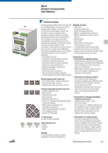
A freely programmable control module <strong>with</strong><br />
non-volatile program memory and 4-line<br />
alphanumeric display monitors and<br />
controls the central battery system. All<br />
functions such as charging, mains/<br />
emergency lighting selection and deep<br />
discharge protection of the devices and<br />
the emergency luminaires are tested<br />
automatically. Any faults that occur are<br />
signalled immediately. An interface enables<br />
a central monitoring facility to be<br />
connected. In the event of a short circuit or<br />
open circuit in current loops, differential<br />
monitors immediately power on the system<br />
(maintained light) or put the system in<br />
readiness.<br />
– Nonvolatile memory<br />
– Automatic luminaire search function<br />
– Individual luminaire monitoring<br />
– Automatic DLS/TLS search function<br />
– Selective manual reset/circuit<br />
– Selective emergency light/circuit<br />
– Password function<br />
– Final circuit fuse monitoring<br />
– Module-selective battery operation<br />
– Control module <strong>with</strong> multi-master-mode M3 Control module<br />
Sealed keypad <strong>with</strong> 3 keys for:<br />
– Test (mains failure - battery operation)<br />
– Function test start / cancel<br />
– Operating duration test start / cancel<br />
3 freely assignable function keys for:<br />
– <strong>System</strong> disable/enable<br />
– Manual reset<br />
– Cancel function test<br />
– Show fault list<br />
– Maintained light off/on<br />
– Power on complete safety lighting system<br />
(continuity lighting)<br />
– Mains failure simulation UV-A<br />
(emergency operation)<br />
– Reset deep discharge protection<br />
– Find insulation failure<br />
– Service Pin Message<br />
7 control keys<br />
for user-friendly navigation<br />
LED indicators for:<br />
– Mains<br />
– <strong>Battery</strong><br />
– Fault<br />
Display:<br />
4 x 20 characters, backlit, program<br />
adjustable contrast and brightness.<br />
Displays include:<br />
– Date/Time<br />
– Charging malfunction<br />
– Deep discharge protection<br />
– <strong>Battery</strong> voltage/charge current (+)<br />
– <strong>Battery</strong> discharge current in test or<br />
failure (-)<br />
– Manual reset<br />
– Test mode<br />
– Delay-time on mains return<br />
(remaining time in min.)<br />
– Luminaire failure <strong>with</strong> location label<br />
– Insulation fault <strong>with</strong> circuit indication<br />
– Failure mains sub DB (<strong>with</strong> location label)<br />
– Failure/programming information<br />
Connections:<br />
– Connection for disable switch:<br />
Control loops for blocking the installation<br />
during factory shutdowns <strong>with</strong> differential<br />
loop monitoring for short-circuit and<br />
open circuit detection.<br />
Differential monitoring: Short-circuit or<br />
open circuit result in readiness for<br />
operation of the system.<br />
– Connection for phase monitor:<br />
24V current loop for requesting<br />
emergency lighting using differential loop<br />
monitoring for the detection of shortcircuit<br />
and open circuits.<br />
Differential monitoring: Short-circuit or<br />
open circuit result in the immediate<br />
power on (maintained light) of the<br />
system.<br />
– Connection for floating signalling<br />
contacts and buzzer:<br />
3 floating relays, each 1x UM,<br />
24V 0.5A; buzzer<br />
One or more of 11 different signals can<br />
be assigned to each floating contact or<br />
to the buzzer. Freely programmable,<br />
DIN VDE 0108 requirement can be<br />
called at any time as a preset.<br />
– Connection for analog inputs:<br />
4 off freely assignable 24 V analog<br />
inputs, can be programmed negated<br />
and non negated, e.g. for start / cancel<br />
function test, start / cancel operating<br />
duration test, disable / enable system,<br />
manual reset, maintained light on / off,<br />
power on safety lighting as continuity<br />
lighting.<br />
<strong>CEAG</strong> Notlichtsysteme GmbH 3/11<br />
3