Testplan Cards and Inlays - AIT Austrian Institute of Technology
Testplan Cards and Inlays - AIT Austrian Institute of Technology
Testplan Cards and Inlays - AIT Austrian Institute of Technology

You also want an ePaper? Increase the reach of your titles
YUMPU automatically turns print PDFs into web optimized ePapers that Google loves.
MIFARE TM<br />
Test plan for MIFARE TM Air-Interface<br />
Compatibility<br />
Certification <strong>of</strong> <strong>Cards</strong><br />
Qualification <strong>of</strong> <strong>Inlays</strong><br />
Single <strong>and</strong> Double UID<br />
Version 2.12<br />
Date <strong>of</strong> Issue: 21.05.2012<br />
MIFARE is a registered trademark <strong>of</strong> NXP Semiconductors<br />
Document approved by Thomas Sumberger 21.05.2012<br />
Certification <strong>Institute</strong><br />
MIFARE TM<br />
Certification <strong>Institute</strong><br />
<strong>AIT</strong> – <strong>Austrian</strong> <strong>Institute</strong> <strong>of</strong> <strong>Technology</strong> G.m.b.H.<br />
A-1210 Vienna, Giefinggasse 2, Austria<br />
Phone: +43 (0) 50550 Ext. 6555 Fax: +43 (0) 50550 Ext. 6439 e-mail: mci@ait.ac.at
Revision History<br />
Revision Date Description Author<br />
2.10 20100112 Updated br<strong>and</strong> name (former Arsenal<br />
Research to <strong>AIT</strong> – <strong>Austrian</strong> <strong>Institute</strong> <strong>of</strong><br />
<strong>Technology</strong>)<br />
J. S<strong>and</strong>era<br />
2.11 20120215 Changed label Acceptance <strong>of</strong> Pause to<br />
PICC Reception<br />
Updated current dates <strong>of</strong> st<strong>and</strong>ards <strong>and</strong><br />
related documents<br />
Added additional waveforms to testplan to<br />
be according current st<strong>and</strong>ards (ISO_1,<br />
ISO_2 <strong>and</strong> ISO_2 – refer to Table III)<br />
Changed test limits <strong>of</strong> Hmax from 6 A/m to<br />
7.5 A/m <strong>and</strong> C-sideb<strong>and</strong> levels from 30/H 1.2<br />
to 22/H 0.5 - refer to Table I<br />
2.12 20120521 Added Revision history,<br />
Company Name (former ÖFPZ Arsenal<br />
GmbH to <strong>AIT</strong>- <strong>Austrian</strong> <strong>Institute</strong> <strong>of</strong><br />
<strong>Technology</strong> GmbH) updated<br />
T.Sumberger<br />
T.Sumberger<br />
<strong>AIT</strong> <strong>Austrian</strong> <strong>Institute</strong> <strong>of</strong> <strong>Technology</strong> Test plan cards V 2.12 Page 2/17<br />
MIFARE TM Certification <strong>Institute</strong> MIFARE TM Air-Interface Compatibility
Table <strong>of</strong> contents<br />
1. Introduction ........................................................................................................................ 4<br />
2. Terms <strong>and</strong> definitions ........................................................................................................ 4<br />
3. Certification ....................................................................................................................... 5<br />
3.1. Test samples ............................................................................................................ 5<br />
3.2. Certificate <strong>and</strong> test report ......................................................................................... 5<br />
3.3. Compatibility notes ................................................................................................... 5<br />
3.4. Certification <strong>of</strong> cards ................................................................................................ 5<br />
3.5. Qualification <strong>of</strong> inlays (prelams) ............................................................................... 6<br />
3.6. Validity period ........................................................................................................... 6<br />
3.7. Renewal <strong>of</strong> certificate ............................................................................................... 6<br />
3.8. Test sets ................................................................................................................... 6<br />
3.8.1. Full Card Certification or Inlay Qualification .................................................... 7<br />
3.8.2. Upgrade Certification ...................................................................................... 7<br />
3.8.3. Delta Certification ........................................................................................... 7<br />
3.9. St<strong>and</strong>ards <strong>and</strong> related documents ........................................................................... 8<br />
4. Test plan for MIFARE TM<br />
Air-Interface Compatibility .......................................................... 9<br />
5. Tests <strong>and</strong> Measurements in Detail .................................................................................. 11<br />
5.1. Coil size .................................................................................................................. 11<br />
5.2. Resonance frequency ............................................................................................ 11<br />
5.3. Minimum operating field ......................................................................................... 11<br />
5.4. PICC Reception (Acceptance <strong>of</strong> “Pause”) ............................................................. 12<br />
5.5. Miller decoder ......................................................................................................... 14<br />
5.6. Frame delay time PCD to PICC ............................................................................. 14<br />
5.7. Load modulation ..................................................................................................... 15<br />
5.8. Functional test ........................................................................................................ 15<br />
5.9. State machine test ................................................................................................. 16<br />
5.10. Maximum field strength .......................................................................................... 16<br />
5.11. Inlay identification check ........................................................................................ 17<br />
<strong>AIT</strong> <strong>Austrian</strong> <strong>Institute</strong> <strong>of</strong> <strong>Technology</strong> Test plan cards V 2.12 Page 3/17<br />
MIFARE TM Certification <strong>Institute</strong> MIFARE TM Air-Interface Compatibility
1. Introduction<br />
This document describes procedures for testing <strong>of</strong> MIFARE TM<br />
Air-Interface Compatibility <strong>of</strong><br />
cards. The purpose <strong>of</strong> the certification process is to ensure that any certified card <strong>of</strong> one<br />
manufacturer will be able to establish data exchange via the RF-interface with any certified<br />
terminal <strong>of</strong> any other manufacturer. To ensure compatibility a set <strong>of</strong> parameters <strong>and</strong> tests<br />
were defined, that have to be met by both cards <strong>and</strong> terminals.<br />
MIFARE TM<br />
cards are fulfilling this test plan comply with the relevant clauses <strong>of</strong><br />
ISO/IEC 14443 (type A) <strong>and</strong> ISO/IEC 10373-6.<br />
Currently they can be either Single UID (single 32 bit UID) or Double UID (cascaded UID, up<br />
to level 2).<br />
2. Terms <strong>and</strong> definitions<br />
The following list gives a short explanation <strong>of</strong> terms <strong>and</strong> shortcuts used in this document:<br />
Module Chip on a carrier material without connected antenna<br />
Inlay Carrier, containing a chip/module with connected antenna<br />
Card TAG with physical dimensions according to ISO/IEC 7810<br />
PICC Proximity card with physical dimensions according to ISO/IEC 7810<br />
PCD Proximity coupling device – read/write device for PICC<br />
DUT Device under test<br />
RF Radio frequency<br />
ASK Amplitude shift key (modulation)<br />
MCI MIFARE TM<br />
Certification <strong>Institute</strong> (<strong>AIT</strong>)<br />
EOP End <strong>of</strong> "PAUSE"<br />
EOC End <strong>of</strong> communication bit<br />
REQA Request comm<strong>and</strong> (ISO/IEC 14443)<br />
WUPA Wakeup comm<strong>and</strong> (ISO/IEC 14443)<br />
ATQA Answer to a request (ISO/IEC 14443)<br />
Card Identifier Card identification number for administration<br />
UID Unique identification number (Serial number)<br />
SEL Select comm<strong>and</strong> (ISO/IEC 14443)<br />
SAK Select acknowledge (ISO/IEC 14443)<br />
HLTA Halt comm<strong>and</strong> (ISO/IEC 14443)<br />
H Magnetic field strength<br />
C Modulation coefficient<br />
C-carrier Carrier signal load modulation coefficient<br />
C-upper Upper sideb<strong>and</strong> load modulation coefficient<br />
C-lower Lower sideb<strong>and</strong> load modulation coefficient<br />
C-min Minimum load modulation coefficient<br />
A Area<br />
FDT Frame Delay Time (ISO/IEC 14443)<br />
<strong>AIT</strong> <strong>Austrian</strong> <strong>Institute</strong> <strong>of</strong> <strong>Technology</strong> Test plan cards V 2.12 Page 4/17<br />
MIFARE TM Certification <strong>Institute</strong> MIFARE TM Air-Interface Compatibility
3. Certification<br />
3.1. Test samples<br />
Applicants seeking certification have to make available test samples <strong>of</strong> the cards in the<br />
required quantity. Test samples will be kept at MCI for reference. The applicant has to<br />
provide to MCI any information about the construction <strong>of</strong> the cards, used parts <strong>and</strong> their<br />
suppliers <strong>and</strong> subcontractors asked by MCI.<br />
3.2. Certificate <strong>and</strong> test report<br />
For cards having successfully passed all applicable tests <strong>of</strong> this test plan a certificate will be<br />
awarded with the MIFARE TM<br />
Air-Interface Compatible logo showing if the card is single or<br />
double UID. Besides the certificate, the test report containing the individual test results is<br />
h<strong>and</strong>ed out to the applicant.<br />
3.3. Compatibility notes<br />
MIFARE TM<br />
Air-Interface Compatibility is verifying the contactless RF interface only <strong>and</strong> is<br />
therefore applicable to all types <strong>of</strong> MIFARE TM<br />
cards. This certification ensures that basic data<br />
exchange can be established between the card <strong>and</strong> the terminal over the RF-interface only.<br />
No further functionality <strong>of</strong> the card is tested.<br />
MIFARE TM<br />
terminals certified according to the “Test plan for MIFARE TM<br />
Compatibility for<br />
Certification <strong>of</strong> Terminals <strong>and</strong> Qualification <strong>of</strong> Contactless Readers” up to version 2.1 are not<br />
verified to h<strong>and</strong>le cascaded UIDs correctly.<br />
The following table shows the compatibility matrix:<br />
Card<br />
3.4. Certification <strong>of</strong> cards<br />
Reader<br />
Single UID<br />
reader/terminal<br />
Double UID<br />
reader/terminal<br />
Single UID yes yes<br />
Double UID no yes<br />
MIFARE TM<br />
certification is available to card manufacturers for finished cards.<br />
Generally a card comprises <strong>of</strong> an inlay holding the chip <strong>and</strong> antenna coil, which is moulded<br />
into a plastic material, forming the card.<br />
A Full Certification Test is carried out on a submitted card that, in its entity or parts <strong>of</strong> it, has<br />
not been tested for certification or qualification according to this test plan or any prior version<br />
<strong>of</strong> it.<br />
An Upgrade Certification Test can be carried out if the inlay <strong>of</strong> the presented card has<br />
<strong>AIT</strong> <strong>Austrian</strong> <strong>Institute</strong> <strong>of</strong> <strong>Technology</strong> Test plan cards V 2.12 Page 5/17<br />
MIFARE TM Certification <strong>Institute</strong> MIFARE TM Air-Interface Compatibility
already been qualified according to this test plan to obtain a MIFARE TM<br />
Air-Interface<br />
Compatible certificate for the card.<br />
A Delta Certification Test is intended for customers already having a MIFARE TM<br />
Air-Interface<br />
Compatible certificate for their card, but having minor changes (e.g. card material or chip<br />
module). In this case a reduced test set is applicable for re-certification <strong>of</strong> their card.<br />
Test sets for the individual certification tests are described in section 3.8.<br />
3.5. Qualification <strong>of</strong> inlays (prelams)<br />
This test plan introduces the concept <strong>of</strong> qualification for inlays, produced by a third party<br />
manufacturer, who can apply for qualification <strong>of</strong> an inlay without having to produce a<br />
complete card. The test set for qualification <strong>of</strong> an inlay is the same as for certification <strong>of</strong> a<br />
card (Full Certification Test).<br />
By using an inlay that has been qualified according to this test plan a card manufacturer can<br />
apply for certification <strong>of</strong> his card by an Upgrade Certification Test.<br />
3.6. Validity period<br />
A MIFARE TM<br />
certificate <strong>and</strong> MIFARE TM<br />
qualification is valid for a period <strong>of</strong> two years from the<br />
day <strong>of</strong> issue as long as no changes are made to the product. If changes are necessary,<br />
information about the change has to be passed on to the MIFARE TM<br />
Certification <strong>Institute</strong>,<br />
which will decide if it is a minor or major change. For major changes a Full Certification is<br />
required, for minor changes a Delta Certification with a reduced test set is applicable.<br />
Note: A change <strong>of</strong> chip type or coil characteristics always constitute a major change.<br />
Exception: Exchange <strong>of</strong> the chip to another <strong>of</strong> the same type <strong>and</strong> manufacturer, but<br />
with different memory size.<br />
3.7. Renewal <strong>of</strong> certificate<br />
After the MIFARE TM<br />
certificate or MIFARE TM<br />
qualification has expired after two years <strong>and</strong> the<br />
product is still manufactured without change, a renewal <strong>of</strong> the certificate can be applied for<br />
within two years after the expiration. The test set for renewal is that <strong>of</strong> a Delta Certification.<br />
3.8. Test sets<br />
Test sets for the various types <strong>of</strong> certification <strong>and</strong> qualification are defined in the following<br />
tables.<br />
<strong>AIT</strong> <strong>Austrian</strong> <strong>Institute</strong> <strong>of</strong> <strong>Technology</strong> Test plan cards V 2.12 Page 6/17<br />
MIFARE TM Certification <strong>Institute</strong> MIFARE TM Air-Interface Compatibility
3.8.1. Full Card Certification or Inlay Qualification<br />
Test set<br />
Full<br />
Certification<br />
Inlay<br />
Qualification<br />
Number<br />
<strong>of</strong> cards<br />
3.8.2. Upgrade Certification<br />
Test set<br />
Upgrade<br />
Certification<br />
Performed tests<br />
<strong>Testplan</strong><br />
paragraph<br />
Test<br />
temperature<br />
1 Coil size 5.1 ---<br />
5 Maximum field strength 5.10 50°C<br />
10 Resonance frequency<br />
Minimum operating field<br />
PICC Reception<br />
Miller decoder<br />
Frame delay<br />
Load modulation<br />
Functional test<br />
State machine test<br />
Number<br />
<strong>of</strong> cards<br />
3.8.3. Delta Certification<br />
Test set<br />
Delta<br />
Certification<br />
Number<br />
<strong>of</strong> cards<br />
Performed tests<br />
<strong>AIT</strong> <strong>Austrian</strong> <strong>Institute</strong> <strong>of</strong> <strong>Technology</strong> Test plan cards V 2.12 Page 7/17<br />
MIFARE TM Certification <strong>Institute</strong> MIFARE TM Air-Interface Compatibility<br />
5.2<br />
5.3<br />
5.4<br />
5.5<br />
5.6<br />
5.7<br />
5.8<br />
5.9<br />
<strong>Testplan</strong><br />
paragraph<br />
23°C<br />
0 / 23 / 50°C<br />
0 / 23 / 50°C<br />
0 / 23 / 50°C<br />
0 / 23 / 50°C<br />
0 / 23 / 50°C<br />
23°C<br />
23°C<br />
Test<br />
temperature<br />
1 Inlay identification check 5.11 23°C<br />
3 Maximum field strength 5.10 50°C<br />
6 Resonance frequency<br />
Minimum operating field<br />
PICC Reception<br />
Miller decoder<br />
Frame delay<br />
Load modulation<br />
Functional test<br />
State machine test<br />
Performed tests<br />
5.2<br />
5.3<br />
5.4<br />
5.5<br />
5.6<br />
5.7<br />
5.8<br />
5.9<br />
<strong>Testplan</strong><br />
paragraph<br />
23°C<br />
0 / 23 / 50°C<br />
0 / 23 / 50°C<br />
0 / 23 / 50°C<br />
0 / 23 / 50°C<br />
0 / 23 / 50°C<br />
23°C<br />
23°C<br />
Test<br />
temperature<br />
1 Coil size 5.1 ---<br />
3 Maximum field strength 5.10 50°C<br />
6 Resonance frequency<br />
Minimum operating field<br />
PICC Reception<br />
Miller decoder<br />
Frame delay<br />
Load modulation<br />
Functional test<br />
State machine test<br />
5.2<br />
5.3<br />
5.4<br />
5.5<br />
5.6<br />
5.7<br />
5.8<br />
5.9<br />
23°C<br />
23°C<br />
23°C<br />
23°C<br />
23°C<br />
23°C<br />
23°C<br />
23°C
3.9. St<strong>and</strong>ards <strong>and</strong> related documents<br />
Document Title Status Edition/Date<br />
ISO/IEC 14443-1<br />
ISO/IEC 14443-2<br />
Identification cards – Contactless integrated<br />
circuit(s) cards – Proximity cards<br />
Part 1: Physical characteristics<br />
Identification cards – Contactless integrated<br />
circuit(s) cards – Proximity cards<br />
Part 2: Radio frequency power <strong>and</strong> signal<br />
interface<br />
ISO/IEC 14443-3 Identification cards – Contactless integrated<br />
circuit(s) cards – Proximity cards<br />
Part 3: Initialisation <strong>and</strong> anticollision<br />
ISO/IEC 10373-6<br />
Identification cards – Test Methods<br />
Part 6: Proximity cards<br />
IS Ed. 2/2008<br />
IS Ed. 2/2010<br />
IS Ed. 2/2011<br />
<strong>AIT</strong> <strong>Austrian</strong> <strong>Institute</strong> <strong>of</strong> <strong>Technology</strong> Test plan cards V 2.12 Page 8/17<br />
MIFARE TM Certification <strong>Institute</strong> MIFARE TM Air-Interface Compatibility<br />
IS<br />
Ed. 2/2011<br />
ISO/IEC 7810 Identification cards – Physical characteristics IS Ed. 3/2003<br />
MIFARE TM Application Note Card IC Coil Design Guide Rev 3.2 2006/07
4. Test plan for MIFARE TM<br />
Air-Interface Compatibility<br />
Compatibility testing is performed on a batch <strong>of</strong> sample cards, drawn by MCI from a manufacturer’s<br />
production lot.<br />
Tests are performed at st<strong>and</strong>ardised ambient temperature (23°C±3°C), as well as the upper<br />
<strong>and</strong> lower operating temperature limits (see table I).<br />
The test plan shown in table I gives an overview <strong>of</strong> the compatibility tests. The test lot is<br />
divided into two batches, one batch is loaded with maximum field strength according to test<br />
5.10 before all measurements <strong>of</strong> tests 5.2 to 5.9 are performed.<br />
<strong>Cards</strong> are tested under controlled temperature with a conditioning time <strong>of</strong> 30 seconds. For<br />
the actual test the RF field is turned on for 1 second. Measurements are taken at the end <strong>of</strong><br />
the on-time <strong>of</strong> the RF field.<br />
Minimum operating field strength is Hmin = 1.25 A/m (rms), maximum operating field strength<br />
is Hmax = 7.5 A/m (rms).<br />
<strong>AIT</strong> <strong>Austrian</strong> <strong>Institute</strong> <strong>of</strong> <strong>Technology</strong> Test plan cards V 2.12 Page 9/17<br />
MIFARE TM Certification <strong>Institute</strong> MIFARE TM Air-Interface Compatibility
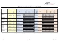
Test / Measurement Test Test<br />
configuration<br />
Coil size 5.1<br />
<strong>AIT</strong> <strong>Austrian</strong> <strong>Institute</strong> <strong>of</strong> <strong>Technology</strong> Test plan cards V 2.12 Page 10/17<br />
MIFARE TM Certification <strong>Institute</strong> MIFARE TM Air-Interface Compatibility<br />
Test limits Magnetic field strength Test temperature Measured value<br />
Aactive > 11200mm²<br />
Amean > 2778.5mm² 1 )<br />
Resonance frequency 5.2 14.5 – 18.5 MHz 23°C fres [MHz]<br />
Minimum Operating field 5.3 ISO/IEC 10373-6 2 ) C = 17.96mV 0°C, 23°C, 50°C<br />
PICC Reception 5.4 ISO/IEC 10373-6<br />
Miller decoder 5.5 ISO/IEC 10373-6<br />
Frame delay time PCD to<br />
PICC<br />
5.6 ISO/IEC 10373-6<br />
Load modulation 5.7 ISO/IEC 10373-6<br />
2<br />
) C-sideb<strong>and</strong> levels<br />
[mV peak] > 22/H 0.5<br />
2<br />
) C-sideb<strong>and</strong> levels<br />
[mV peak] > 22/H 0.5<br />
EOP threshold<br />
5% ... 60%<br />
2 ) C-sideb<strong>and</strong> levels<br />
[mV peak] > 22/H 0.5<br />
23°C<br />
H = 1.25 <strong>and</strong> 7.5 A/m 0°C, 23°C, 50°C<br />
H = 1.25 <strong>and</strong> 7.5 A/m 0°C, 23°C, 50°C<br />
Minimum field<br />
strength<br />
C-carrier <strong>and</strong><br />
C-sideb<strong>and</strong><br />
C-carrier <strong>and</strong><br />
C-sideb<strong>and</strong><br />
H = 1.25 <strong>and</strong> 7.5 A/m 0°C, 23°C, 50°C EOP threshold in %<br />
H = 1.25 - 3 - 4.5 - 6 –<br />
7.5 A/m<br />
0°C, 23°C, 50°C<br />
C-carrier <strong>and</strong><br />
C-sideb<strong>and</strong><br />
Functional test 5.8 H = 1.25 A/m 23°C ATQA, UID, SAK<br />
State machine test 5.9 H = 1.25 A/m 23°C Comm<strong>and</strong> sequence<br />
Maximum field strength 5.10 H = 12.0 A/m max. 50°C<br />
Inlay identification<br />
check 3 )<br />
Notes:<br />
5.11 see 5.11 23°C<br />
1 ) In case a coil <strong>of</strong> more than 4 turns is used, only the 4 largest windings are considered for calculation <strong>of</strong> the mean coil area.<br />
2 ) For the magnetic field strength H < 1.5A/m the load modulation coefficients are valid as calculated for 1.5A/m<br />
3 ) For Upgrade Certification only, see 3.4 <strong>and</strong> 3.5<br />
Table I: Summary <strong>of</strong> compatibility tests
5. Tests <strong>and</strong> Measurements in Detail<br />
The following chapter describes in detail the performed tests on short range <strong>and</strong> proximity<br />
cards (PICCs), their configuration, setup <strong>and</strong> limits for MIFARE TM Air-interface Compatibility<br />
certification.<br />
5.1. Coil size<br />
The card is screened with a high power fluorescent lamp to detect the location <strong>of</strong> the coil <strong>and</strong><br />
the chip inside the PICC. The coil size is checked with a diaphragm with an aperture showing<br />
the mean coil area defined in the MIFARE TM Card IC Coil Design Guide. The active coil area<br />
is the sum <strong>of</strong> the area enclosed by each turn <strong>of</strong> the coil <strong>and</strong> the mean coil area is the active<br />
coil area divided by the number <strong>of</strong> turns. Limits for the active coil area are Aactive > 11200mm²<br />
<strong>and</strong> for the mean coil area Amean > 2778.5mm². For cards with coils having more than 4 turns,<br />
only the 4 largest windings are considered for the calculation <strong>of</strong> the mean coil area Amean. The<br />
barycentre <strong>of</strong> the mean coil area shall be centric on the card with a maximum deviation <strong>of</strong><br />
±6mm from geometric card centre. (see MIFARE TM Card IC Coil Design Guide).<br />
5.2. Resonance frequency<br />
The resonance frequency <strong>of</strong> the card is measured using a RLC meter connected to the<br />
calibration coil (which is specified in ISO/IEC 10373-6 for field strength measurement). For<br />
the measurement the PICC to test is placed directly on the calibration coil to achieve close<br />
coupling. The value <strong>of</strong> the equivalent series resistor is measured for various frequencies<br />
finding out the frequency where the maximum <strong>of</strong> the equivalent series resistor is measured,<br />
which will be the resonance frequency <strong>of</strong> the card.<br />
The measurement is performed at st<strong>and</strong>ard ambient temperature.<br />
The limits for acceptance are:<br />
5.3. Minimum operating field<br />
min. max.<br />
fres in MHz 14.5 18.5<br />
The field strength is raised <strong>and</strong> the level at which the PICC begins to operate is measured.<br />
The minimum operating field has to be below Hmin = 1.25 A/m (rms value).<br />
The operation <strong>of</strong> the PICC is documented by the measurement <strong>of</strong> the load modulation<br />
coefficients which are valid for a field strength <strong>of</strong> 1.5 A/m (carrier <strong>and</strong> sideb<strong>and</strong> levels,<br />
see 5.7).<br />
The test PCD assembly as described in ISO/IEC 10373-6 (Annex A) is used to drive the<br />
PICC under test <strong>and</strong> to measure the response <strong>of</strong> it. The basic measurement equipment is<br />
shown in figure 1.<br />
For measurement <strong>of</strong> the magnetic field strength using the calibration coil see<br />
ISO/IEC 10373-6.<br />
<strong>AIT</strong> <strong>Austrian</strong> <strong>Institute</strong> <strong>of</strong> <strong>Technology</strong> Test plan cards V 2.12 Page 11/17<br />
MIFARE TM Certification <strong>Institute</strong> MIFARE TM Air-Interface Compatibility
The test is performed at ambient temperature as well as both minimum <strong>and</strong> maximum<br />
specified temperature.<br />
For this test a st<strong>and</strong>ard modulation pulse signal shall be used as shown in figure 2 with the<br />
rise <strong>and</strong> fall times defined in table II.<br />
Test pattern t1 t2 t3 t4<br />
[µs] [µs] [µs] [µs]<br />
T1 MID 2.5 1.0 1.0 0.4<br />
Table II: Timing parameters for st<strong>and</strong>ard modulation pulse<br />
Arbitrary<br />
Waveform<br />
Generator<br />
Amplifier<br />
trigger signal<br />
sense coil a<br />
DUT<br />
R sense<br />
Fig. 1: Basic PICC measurement setup<br />
5.4. PICC Reception (Acceptance <strong>of</strong> “Pause”)<br />
Digital Storage<br />
Oscilloscope<br />
PCD antenna<br />
sense coil b<br />
Calibration coil<br />
Communication between PCD <strong>and</strong> PICC takes place using the modulation principle <strong>of</strong> ASK<br />
with a modulation index <strong>of</strong> 100%, creating a pulse as shown in figure 4.2, called “PAUSE”.<br />
This test verifies the acceptance <strong>of</strong> the pulses with various length <strong>and</strong> shape sent by the<br />
PCD.<br />
The test setup is described in figure 1. Without a PICC in the test setup the amplifier level is<br />
adjusted until the desired field strength is reached, using the output <strong>of</strong> the calibration coil for<br />
calculating the magnetic field strength. Then the PICC is placed in the DUT position. A<br />
<strong>AIT</strong> <strong>Austrian</strong> <strong>Institute</strong> <strong>of</strong> <strong>Technology</strong> Test plan cards V 2.12 Page 12/17<br />
MIFARE TM Certification <strong>Institute</strong> MIFARE TM Air-Interface Compatibility
equest (REQA) comm<strong>and</strong>s is sent to the PICC while checking the response on the digital<br />
storage oscilloscope. The operation <strong>of</strong> the PICC is documented by the presence <strong>of</strong> load<br />
modulation coefficients (carrier <strong>and</strong> sideb<strong>and</strong> levels, see 5.7). The test is run with a set <strong>of</strong><br />
differently shaped pulses to test worst case conditions.<br />
The test is performed at ambient temperature as well as both minimum <strong>and</strong> maximum<br />
specified temperature (see table I). Tested field strengths are Hmin <strong>and</strong> Hmax.<br />
Envelope <strong>of</strong> carrier amplitude<br />
110%<br />
100%<br />
90%<br />
60%<br />
5%<br />
5%<br />
60%<br />
90%<br />
100%<br />
110%<br />
Test pattern<br />
<strong>AIT</strong> <strong>Austrian</strong> <strong>Institute</strong> <strong>of</strong> <strong>Technology</strong> Test plan cards V 2.12 Page 13/17<br />
MIFARE TM Certification <strong>Institute</strong> MIFARE TM Air-Interface Compatibility<br />
t4<br />
t2<br />
t1 t3<br />
Fig. 2: Modulation pulse “PAUSE”<br />
t1<br />
[µs]<br />
t2<br />
[µs]<br />
t3<br />
[µs]<br />
t4<br />
[µs]<br />
ISO Scenario 1 3.0 0.6 1.2 0.5<br />
ISO Scenario 2 2 ) 2.0 1.6 1.0 0.5<br />
ISO Scenario 3 2 ) 3.0 0.5 0.25 0.14<br />
T1 MAX 3 ) 3.0 1.4 1.0 0.4<br />
T1 MIN 3 ) 2.0 0.7 1.0 0.4<br />
T2 5% 3 ) 3.0 1.5 1.0 0.4<br />
HUMP 1 ) 3.0 1.0 1.0 0.4<br />
Table III: Timing parameters for modulation pulses<br />
1<br />
) Falling edge does not decrease monotonically but has a local maximum <strong>of</strong> 10% with a time<br />
interval <strong>of</strong> 0.5µs between the local maximum <strong>and</strong> the point <strong>of</strong> passing the 10%-level before.<br />
2<br />
) Waveforms with 10% overshoot<br />
3<br />
) This waveforms will be used for chip types, which were developed according to ISO<br />
14443:2001.<br />
t
5.5. Miller decoder<br />
This test verifies the correct decoding <strong>of</strong> the pulses sent to the PICC <strong>and</strong> checks the<br />
sensitivity to tolerances <strong>of</strong> the "PAUSE" pulse with respect to its position in the bit-frame.<br />
Fig. 3: Timing <strong>of</strong> pulses sent to PICC<br />
Limits stated in table IV shall apply for MIFARE TM Certification <strong>of</strong> PICCs.<br />
Pattern / Parameter<br />
MILLER MIN<br />
MILLER MAX<br />
periods <strong>of</strong><br />
fc = 13.56 MHz<br />
value in µs<br />
t1 116 8.47<br />
t2 180 13.14<br />
t3 244 17.81<br />
t1 140 10.22<br />
t2 204 14.89<br />
t3 268 19.56<br />
Table IV: Limits for "PAUSE" pulse timing with respect to bit-frame<br />
The test is performed in the setup described in figure 1 using wakeup (WUPA) comm<strong>and</strong>s,<br />
which are sent to the PICC while checking the response on the digital storage oscilloscope.<br />
As modulation pulse a “PAUSE” with a length <strong>of</strong> 36 periods (2,65µs) is used. The test is run<br />
with a set <strong>of</strong> maximum <strong>and</strong> minimum parameters to test worst case conditions. Timing values<br />
are measured as seen in Fig. 3..<br />
Tested field strengths are Hmin <strong>and</strong> Hmax. Test temperatures are ambient <strong>and</strong> both minimum<br />
<strong>and</strong> maximum (see table I).<br />
5.6. Frame delay time PCD to PICC<br />
The purpose <strong>of</strong> this test is to check that the card answers after an exactly defined time<br />
following the last bit sent by the reader, which is essential for the functioning <strong>of</strong> the<br />
anticollision. The test circuit is the same as for PICC Reception test. Test comm<strong>and</strong>s are<br />
sent to the card <strong>and</strong> the timing is measured. The first modulation bit sent by the PICC have<br />
to start exactly 1172 periods after the rising edge <strong>of</strong> the "PAUSE" <strong>of</strong> the EOC bit, if the last<br />
data bit transmitted is a logic "0", or 1236 periods after the last data bit, if it is a logic "1".<br />
By counting the periods backwards from the first modulation bit <strong>of</strong> the PICC the "End <strong>of</strong><br />
Pause"- (EOP-) threshold is measured using a "PAUSE"-pulse with a flat rising edge.<br />
Limits for the EOP are 5% (minimum) <strong>and</strong> 60% (maximum) <strong>of</strong> the unmodulated carrier level<br />
measured on the calibration coil (see figure 4.1).<br />
<strong>AIT</strong> <strong>Austrian</strong> <strong>Institute</strong> <strong>of</strong> <strong>Technology</strong> Test plan cards V 2.12 Page 14/17<br />
MIFARE TM Certification <strong>Institute</strong> MIFARE TM Air-Interface Compatibility
The test is performed in the setup described in figure 4.1 using request (REQA) comm<strong>and</strong>s,<br />
which are sent to the PICC while checking the response on the digital storage oscilloscope.<br />
Tested field strengths are Hmin <strong>and</strong> Hmax. Test temperatures are ambient <strong>and</strong> both minimum<br />
<strong>and</strong> maximum (see table I).<br />
5.7. Load modulation<br />
REQA to card Start <strong>of</strong> ATQA<br />
Fig. 4: Frame delay time measurement<br />
The test circuit defined in ISO/IEC10373-6 with the setup <strong>of</strong> figure 1 is used. A request<br />
(REQA) comm<strong>and</strong> is repeatedly sent to the PICC while checking the response on the digital<br />
storage oscilloscope. The magnetic field strength is set to the defined levels <strong>of</strong> 1.25 A/m, 3<br />
A/m, 4.5A/m, 6 A/m <strong>and</strong> 7.5 A/m by measurement through the calibration coil. The st<strong>and</strong>ard<br />
timing <strong>of</strong> modulation pulse “PAUSE” defined in figure 2 <strong>and</strong> table II shall be used. Stored<br />
data in the digital oscilloscope is read out <strong>and</strong> processed by a computer. Carrier <strong>and</strong><br />
sideb<strong>and</strong> levels are calculated by a discrete Fourier transformation as defined in ISO/IEC<br />
10373-6. The calculated load modulation amplitude shall be at least C = 22/H 0.5 (mVpeak),<br />
where H is the magnetic field strength in A/m (rms). For the magnetic field strength H <<br />
1.5A/m the load modulation coefficients are valid as calculated for 1.5A/m.<br />
Test temperatures are ambient <strong>and</strong> both minimum <strong>and</strong> maximum (see table I).<br />
5.8. Functional test<br />
A computer controlled test setup incorporating a reader module is used to test the basic<br />
functionality <strong>of</strong> the PICC. This tests check that the PICC answers correctly to a request<br />
(REQA) comm<strong>and</strong> with a answer to request (ATQA) <strong>and</strong> performs a full sequence<br />
anticollision loop as defined in ISO/IEC 14443-3. Then reading <strong>of</strong> the serial number (UID)<br />
<strong>and</strong> selecting <strong>of</strong> the PICC is tested. Finally a check <strong>of</strong> the acknowledge (SAK) sent by the<br />
PICC according to the definitions made in ISO/IEC 14443-3 is done. For PICCs with double<br />
UID the byte 'uid[0]' shall specify the IC-manufacturer as given in the Registration Sheet.<br />
Tested field strength is Hmin. Test temperature is ambient (see table I).<br />
<strong>AIT</strong> <strong>Austrian</strong> <strong>Institute</strong> <strong>of</strong> <strong>Technology</strong> Test plan cards V 2.12 Page 15/17<br />
MIFARE TM Certification <strong>Institute</strong> MIFARE TM Air-Interface Compatibility
5.9. State machine test<br />
A computer controlled test setup incorporating a reader module is used to test the correct<br />
sequence <strong>of</strong> comm<strong>and</strong>s according to the definitions made in ISO/IEC 14443-3 <strong>and</strong> a typical<br />
anticollision loop on two cards.<br />
Tested field strength is Hmin. Test temperature is ambient (see table I).<br />
REQA,<br />
WUPA,<br />
nAC,<br />
nSEL,<br />
HLTA<br />
Error<br />
REQA,<br />
WUPA,<br />
AC,<br />
nAC,<br />
SEL,<br />
nSEL<br />
Error<br />
5.10. Maximum field strength<br />
HALT<br />
State<br />
WUPA<br />
READY*<br />
State<br />
SEL<br />
ACTIVE*<br />
State<br />
REQA,<br />
AC<br />
nAC,<br />
SEL,<br />
nSEL,<br />
HLTA<br />
Error<br />
REQA,<br />
WUPA,<br />
AC,<br />
nAC,<br />
SEL,<br />
nSEL<br />
Error<br />
IDLE<br />
State<br />
REQA, WUPA<br />
READY<br />
State AC<br />
<strong>AIT</strong> <strong>Austrian</strong> <strong>Institute</strong> <strong>of</strong> <strong>Technology</strong> Test plan cards V 2.12 Page 16/17<br />
MIFARE TM Certification <strong>Institute</strong> MIFARE TM Air-Interface Compatibility<br />
AC<br />
Enter<br />
ISO/IEC 14443-4<br />
ISO/IEC 14443-4<br />
HLTA DESEL<br />
REQA,<br />
WUPA,<br />
nAC,<br />
nSEL,<br />
HLTA<br />
Error<br />
Fig. 5: State machine diagram<br />
Power OFF<br />
Reset<br />
SEL<br />
ACTIVE<br />
State<br />
HLTA<br />
AC<br />
nAC,<br />
SEL,<br />
nSEL,<br />
HLTA<br />
Error<br />
The tested cards are exposed to a magnetic field strength <strong>of</strong> 12A/m for 25s followed by an<br />
<strong>of</strong>f-state for 5s repeated twice at the carrier frequency (13.56MHz). This results in average<br />
field strength levels <strong>of</strong> 10A/m for an averaging period <strong>of</strong> 30s according<br />
to the definitions made in ISO/IEC 14443-1.
Ambient temperature is 50°C, total duration <strong>of</strong> exposure is one minute.<br />
After the exposure the full test programme will be performed <strong>and</strong> the results have to be within<br />
the specified limits.<br />
5.11. Inlay identification check<br />
This test is only applicable for a MIFARE TM Upgrade Certification. In this case it is necessary<br />
to prove that the inlay <strong>of</strong> the submitted card is the same as qualified earlier by a MIFARE TM<br />
Inlay Qualification.<br />
The inlay identification check comprises a test <strong>of</strong> visual <strong>and</strong> electrical parameters, defined in<br />
the following table:<br />
Test group Tests<br />
Visual<br />
Electrical<br />
All tests are carried out at 23°C only.<br />
<strong>Testplan</strong><br />
paragraph<br />
Max. deviation from qualified<br />
inlay<br />
Coil size <strong>and</strong> layout 5.1 ±0.5mm in either axis<br />
Coil type <strong>and</strong> material same type <strong>and</strong> material<br />
Module same module<br />
Resonance frequency 5.2 ±300 kHz<br />
Minimum operating field 5.3 ±0.1 A/m<br />
Load modulation 5.7 ±5mV<br />
<strong>AIT</strong> <strong>Austrian</strong> <strong>Institute</strong> <strong>of</strong> <strong>Technology</strong> Test plan cards V 2.12 Page 17/17<br />
MIFARE TM Certification <strong>Institute</strong> MIFARE TM Air-Interface Compatibility