

Preferential thermal nitridation to form pin-hole free - Oak Ridge ...
Preferential thermal nitridation to form pin-hole free - Oak Ridge ...
Preferential thermal nitridation to form pin-hole free - Oak Ridge ...

Create successful ePaper yourself
Turn your PDF publications into a flip-book with our unique Google optimized e-Paper software.
1018 M.P. Brady et al. / Scripta Materialia 50 (2004) 1017–1022<br />
Pin-<strong>hole</strong> defects are not an issue for <strong>thermal</strong> <strong>nitridation</strong><br />
and related oxidation reactions because at elevated<br />
temperatures thermodynamic and kinetic fac<strong>to</strong>rs favor<br />
reaction of all exposed metal surface. Rather, the key<br />
issues are the extent <strong>to</strong> which the desired element(s) in<br />
the alloy can be preferentially reacted <strong>to</strong> achieve the goal<br />
surface layer composition, the morphology of the layer<br />
(subsurface precipitates vs external continuous), and the<br />
adherence/possible cracking of the layer on cooling.<br />
Control of such phenomena is the basis for protective<br />
oxide scale <strong>form</strong>ation by heat-resistant alloys during<br />
high temperature corrosion e.g. [17,18], but have not<br />
been well explored as a synthesis method <strong>to</strong> <strong>form</strong> protective<br />
functional nitride surface layers.<br />
2. Experimental methods<br />
2.1. Nitridation<br />
Nitrides have been identified as candidate coatings<br />
for metallic bipolar plates due <strong>to</strong> their combination of<br />
high electrical conductivity and good corrosion resistance<br />
[6]. A nitrided model Ni–50Cr alloy was selected<br />
for study, based on screening polarization studies of a<br />
series of nitrided Ni–X base alloys (X ¼ Cr, Nb, Ti, V) in<br />
PEMFC environments [19]. Test coupons of the model<br />
Ni–50Cr (wt.%) alloy were manufactured from arc-cast<br />
and heat treated (1150 °C, 8 h) Ni–50Cr. The coupons<br />
were ground <strong>to</strong> a 240 grit surface finish. Nitridation was<br />
accomplished in an alumina vacuum furnace backfilled<br />
with high-purity nitrogen <strong>to</strong> 1 atm; the nitrogen flow<br />
was s<strong>to</strong>pped and the coupon was heated <strong>to</strong> 1100 °C, held<br />
for 1–2 h, and furnace cooled <strong>to</strong> room temperature. The<br />
mass gain due <strong>to</strong> nitrogen uptake was 1.9–2.3 mg/cm 2 .<br />
Nitridation for the anode and cathode plates for the fuel<br />
cell test were conducted in a graphite hot press. They<br />
were heated <strong>to</strong> 1100 °C in slowly flowing, high-purity<br />
nitrogen, held for 2.25 h, and furnace cooled. Mass<br />
gains were 2.25 and 1.75 mg/cm 2 , respectively, for the<br />
anode and cathode plates (nitrided in two separate<br />
runs).<br />
2.2. Corrosion test cell<br />
Long-term exposure in PEMFC anode (reducing)<br />
and cathode (oxidizing) bipolar plate environments was<br />
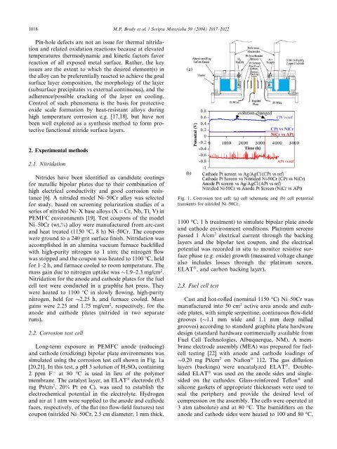
simulated using the corrosion test cell shown in Fig. 1a<br />
[20,21]. In this test, a pH 3 solution of H2SO4 containing<br />
2 ppm F at 80 °C is used in lieu of the polymer<br />
membrane. The catalyst layer, an ELAT â electrode (0.5<br />
mg Pt/cm 2 , 20% Pt on C), was used <strong>to</strong> establish the<br />
electrochemical potential in the electrolyte. Hydrogen<br />
and air at 1 atm were supplied <strong>to</strong> the anode and cathode<br />
faces, respectively, of the flat (no flow-field features) test<br />
coupon (nitrided Ni–50Cr, 2.5 cm diameter, 1 mm thick,<br />
Fig. 1. Corrosion test cell: (a) cell schematic and (b) cell potential<br />
transients for nitrided Ni–50Cr.<br />
1100 °C, 1 h treatment) <strong>to</strong> simulate bipolar plate anode<br />
and cathode environment conditions. Platinum screens<br />
passed 1 A/cm 2 electrical current through the backing<br />
layers and the bipolar test coupon, and the electrical<br />
potential was recorded in situ <strong>to</strong> moni<strong>to</strong>r resistive surface<br />
phase (e.g. oxide) growth (measured voltage change<br />
also includes losses through the platinum screen,<br />
ELAT â , and carbon backing layer).<br />
2.3. Fuel cell test<br />
Cast and hot-rolled (nominal 1150 °C) Ni–50Cr was<br />
manufactured in<strong>to</strong> 50 cm 2 active area anode and cathode<br />
plates, with simple serpentine, continuous flow-field<br />
grooves ( 1.1 mm wide and 1.1 mm deep milled<br />
grooves) according <strong>to</strong> standard graphite plate hardware<br />
design (standard hardware commercially available from<br />
Fuel Cell Technologies, Albuquerque, NM). A membrane<br />
electrode assembly (MEA) was prepared for fuelcell<br />
testing [22] with anode and cathode loadings of<br />
0.20 mg Pt/cm 2 on Nafion â 112. The gas diffusion<br />
layers (backings) were uncatalyzed ELAT â . Doublesided<br />
ELAT â was used on the anode sides and singlesided<br />
on the cathodes. Glass-reinforced Teflon â and<br />
silicone gaskets of appropriate thicknesses were used <strong>to</strong><br />
seal the periphery and provide the desired level of<br />
compression on the assembly. The cells were operated at<br />
3 atm (absolute) and at 80 °C. The humidifiers on the<br />
anode and cathode sides were heated <strong>to</strong> 100 and 80 °C,


