

A six-wafer combustion system for a silicon micro gas turbine engine ...
A six-wafer combustion system for a silicon micro gas turbine engine ...
A six-wafer combustion system for a silicon micro gas turbine engine ...

You also want an ePaper? Increase the reach of your titles
YUMPU automatically turns print PDFs into web optimized ePapers that Google loves.
JOURNAL OF MICROELECTROMECHANICAL SYSTEMS, VOL. 9, NO. 4, DECEMBER 2000 517<br />
A Six-Wafer Combustion System <strong>for</strong> a Silicon Micro<br />
Gas Turbine Engine<br />
Amit Mehra, Xin Zhang, Member, IEEE, Arturo A. Ayón, Member, IEEE, Ian A. Waitz, Martin A. Schmidt, and<br />
Christopher M. Spadaccini<br />
Abstract—As part of a program to develop a <strong>micro</strong> <strong>gas</strong> <strong>turbine</strong><br />
<strong>engine</strong> capable of producing 10–50 W of electrical power in<br />
a package less than one cubic centimeter in volume, we present<br />
the design, fabrication, packaging, and experimental test results<br />
<strong>for</strong> the 6-<strong>wafer</strong> <strong>combustion</strong> <strong>system</strong> <strong>for</strong> a <strong>silicon</strong> <strong>micro</strong><strong>engine</strong>. Comprising<br />
the main nonrotating functional components of the <strong>engine</strong>,<br />
the device described herein measures 2.1 cm 2.1 cm 0.38 cm<br />
and is largely fabricated by deep reactive ion etching through a<br />
total thickness of 3800 m. Complete with a set of fuel plenums,<br />
pressure ports, fuel injectors, igniters, fluidic interconnects, and<br />
compressor and <strong>turbine</strong> static airfoils, this structure is the first<br />
demonstration of the complete hot flow path of a multilevel <strong>micro</strong><br />
<strong>gas</strong> <strong>turbine</strong> <strong>engine</strong>. The 0.195 cmQ <strong>combustion</strong> chamber is shown<br />
to sustain a stable hydrogen flame over a range of operating mass<br />
flows and fuel–air mixture ratios and to produce exit <strong>gas</strong> temperatures<br />
in excess of 1600 K. It also serves as the first experimental<br />
demonstration of stable hydrocarbon <strong>micro</strong><strong>combustion</strong> within the<br />
structural constraints of <strong>silicon</strong>. Combined with longevity tests at<br />
elevated temperatures <strong>for</strong> tens of hours, these results demonstrate<br />
the viability of a <strong>silicon</strong>-based <strong>combustion</strong> <strong>system</strong> <strong>for</strong> <strong>micro</strong> heat<br />
<strong>engine</strong> applications. [539]<br />
Index Terms—Micro<strong>combustion</strong>, <strong>micro</strong>-<strong>gas</strong> <strong>turbine</strong> <strong>engine</strong>,<br />
power MEMS.<br />
I. INTRODUCTION<br />
RECENT advances in the field of <strong>silicon</strong> <strong>micro</strong>fabrication<br />
technology have opened the potential <strong>for</strong> miniature <strong>combustion</strong><br />
<strong>engine</strong>s <strong>for</strong> portable power generation and <strong>micro</strong> air vehicle<br />
propulsion applications [1]. As part of a current Massachusetts<br />
Institute of Technology (MIT) program to develop such<br />
technologies, Epstein et al. [2] and Groshenry [3] have reported<br />
the design <strong>for</strong> a <strong>micro</strong> <strong>gas</strong> <strong>turbine</strong> generator capable of producing<br />
10–50 W of electrical power while consuming 7 g of<br />
jet fuel per hour.<br />
A discussion of relevant combustor scaling laws and preliminary<br />
assessments of several combustor concepts <strong>for</strong> these appli-<br />
Manuscript received February 22, 2000. This work was supported by ARO,<br />
Dr. R. Paur technical manager, and by DARPA, Dr. S. Wilson technical manager.<br />
Portions of this work were presented at the International Conference on Solid<br />
State Sensors and Actuators, Sendai, Japan, 1999. Subject Editor, W. N. Sharpe,<br />
Jr.<br />
A. Mehra, I. Waitz, and C. Spadaccini are with the Gas Turbine Laboratory,<br />
Department of Aeronautics and Astronautics, Massachusetts Institute of Technology,<br />
Cambridge, MA 02139 USA.<br />
X. Zhang and M. Schmidt are with the Micro<strong>system</strong>s Technology Laboratories,<br />
Department of Electrical Engineering and Computer Science, Massachusetts<br />
Institute of Technology, Cambridge, MA 02139 USA.<br />
A. Ayón was with the Micro<strong>system</strong>s Technology Laboratories, Department of<br />
Electrical Engineering and Computer Science, Massachusetts Institute of Technology,<br />
Cambridge, MA 02139 USA. He is now with Sony Semiconductor, San<br />
Antonio, TX 78245 USA.<br />
Publisher Item Identifier S 1057-7157(00)10868-6.<br />
1057–7157/00$10.00 © 2000 IEEE<br />
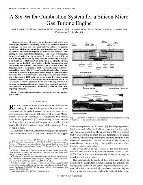
Fig. 1. Schematics of the baseline <strong>engine</strong> and combustor configurations, along<br />
with an SEM of the first <strong>silicon</strong> <strong>micro</strong>combustor.<br />
cations were presented by Waitz et al. [4]. Stable hydrogen <strong>combustion</strong><br />
in a <strong>micro</strong>fabricated <strong>silicon</strong> combustor <strong>for</strong> this <strong>engine</strong><br />
was first demonstrated by Mehra and Waitz [5], who showed<br />
that it was possible to attain exit <strong>gas</strong> temperatures in excess<br />
of 1800 K without compromising the structural integrity of the<br />
0.066 cm <strong>combustion</strong> chamber. An SEM of this <strong>silicon</strong> <strong>micro</strong>combustor<br />
is shown in Fig. 1, along with a schematic of the<br />
baseline <strong>engine</strong> configuration.<br />
The device shown in Fig. 1 served as the first demonstration<br />
of a high power density <strong>micro</strong><strong>combustion</strong> <strong>system</strong> ( 2000<br />
MW/m [6]); ef<strong>for</strong>ts were subsequently undertaken to integrate<br />
it with the rest of the <strong>engine</strong>.<br />
This paper reports the results of those integration ef<strong>for</strong>ts by<br />
presenting the design, fabrication, packaging, and experimental<br />
testing of the combustor in a typical <strong>engine</strong> configuration. Complete<br />
with fuel plenums and injection holes, pressure diagnostics,<br />
igniters, and compressor and <strong>turbine</strong> static airfoils, the re-
518 JOURNAL OF MICROELECTROMECHANICAL SYSTEMS, VOL. 9, NO. 4, DECEMBER 2000<br />
Fig. 2. Schematic and SEM cross-section of half of the axisymmetric 6-<strong>wafer</strong> static structure. (Note that the dies on the <strong>wafer</strong> had two types of combustor inlet<br />
holes-one type had slots as shown in Fig. 3, and the other had an annular opening as shown above.)<br />
sulting device is referred to as the “static structure” and serves<br />
as the first demonstration of the completed hot flow path of a<br />
multilevel <strong>micro</strong> <strong>gas</strong> <strong>turbine</strong> <strong>engine</strong>.<br />
The paper is specifically intended to<br />
1) describe the use of deep reactive ion etching and aligned<br />
fusion bonding to fabricate a 3800- m thick, 6-<strong>wafer</strong><br />
level static structure <strong>for</strong> a <strong>micro</strong><strong>engine</strong>;<br />
2) present a unique design that allows high-temperature,<br />
high-efficiency hydrogen <strong>micro</strong><strong>combustion</strong> in the device<br />
over a range of fuel–air ratios and with low overall heat<br />
loss;<br />
3) present the first experimental demonstration of stable<br />
hydrocarbon <strong>micro</strong><strong>combustion</strong> within the structural<br />
constraints of a <strong>silicon</strong> device.<br />
Be<strong>for</strong>e describing the detailed design, fabrication, and test results<br />
of the static structure, however, we begin by presenting an<br />
overview of the challenges facing <strong>micro</strong>combustor design.<br />
II. MICROCOMBUSTOR DESIGN ISSUES<br />
The ability to transfer the chemical energy of a fuel into a<br />
fluid at high mass flow rates and in small volumes makes the<br />
power density of a <strong>micro</strong>combustor particularly appealing <strong>for</strong><br />
portable power generation and <strong>micro</strong>propulsion applications<br />
[6]. The realization of high power density, however, requires<br />
effective completion of the <strong>combustion</strong> process within a small<br />
volume and is there<strong>for</strong>e fundamentally limited by the chemical<br />
reaction time constraints of the fuel. Tailoring the fluid flow<br />
to stabilize the flame and allow effective mixing of the cold<br />
reactants with the hot products is there<strong>for</strong>e critical to getting<br />
the fuel to completely react within a short time and constitutes<br />
a fundamental design challenge.<br />
This chemical kinetics constraint is also exacerbated by<br />
the enhanced heat transfer effects that result from the large<br />
surface area-to-volume ratio of these devices. Not only does<br />
this high heat loss make it impossible to achieve conventional<br />
combustor efficiencies in excess of 99.9%, but it also increases<br />
chemical reaction times by lowering the temperature of the<br />
flame stabilization zones. The coupling between the fluid<br />
dynamics, heat transfer, and chemical kinetics is there<strong>for</strong>e<br />
much more pronounced <strong>for</strong> these small <strong>system</strong>s and is a critical<br />
element of the design process.<br />
The design space is further complicated by the addition<br />
of a third factor—the material and fabrication constraints.<br />
While <strong>silicon</strong> <strong>micro</strong>fabrication is instrumental to achieving the<br />
economy and high tolerances necessary to make a <strong>micro</strong><strong>engine</strong><br />
viable, it is still largely limited to rudimentary 3-D geometries.<br />
Furthermore, while creep constraints in the rotating components<br />
limit wall temperatures to 900 K [7], chemical kinetics<br />
demand higher temperatures to achieve stable and efficient<br />
<strong>combustion</strong>. The walls of the combustor there<strong>for</strong>e have to<br />
be cooled below the operating <strong>gas</strong> temperatures inside the<br />
chamber. Since cooling the hot chamber walls can adversely<br />
impact the efficiency of the combustor, designing a device that<br />
is efficient, yet structurally durable, poses a significant design<br />
challenge.<br />
The design of a <strong>micro</strong>combustor there<strong>for</strong>e mandates careful<br />
tradeoffs between power output, thermodynamic cycle parameters<br />
associated with the <strong>engine</strong>, physical dimensions, and material<br />
and manufacturing capabilities. These design considerations<br />
are described in the following sections. 1<br />
III. DESIGN OF THE STATIC STRUCTURE<br />
A schematic of the static structure is shown in Fig. 2, alongside<br />
an SEM of the fully-bonded 6-<strong>wafer</strong> device. Detailed views<br />
of each of the <strong>wafer</strong>s prior to bonding are also shown in Fig. 3,<br />
along with an exploded 3-D schematic of the individual <strong>wafer</strong>s.<br />
As highlighted on the pictures, air enters the device axially and<br />
makes a right angle turn into the compressor. In the absence of<br />
a spinning rotor, stationary compressor blades are used to provide<br />
the requisite flow angle into the combustor. Fuel is injected<br />
through a circular array of holes and allowed to mix with the air<br />
as it flows through the combustor recirculation jacket. The flow<br />
then enters the combustor through an axial inlet, burns in the<br />
0.195 cm annular shaped volume, and finally exhausts through<br />
<strong>turbine</strong> static vanes that were designed to maintain an elevated<br />
operating pressure in the chamber by choking the flow. (In the<br />
<strong>engine</strong>, the flow would also pass through the spinning <strong>turbine</strong><br />
rotor <strong>for</strong> power extraction prior to being exhausted out of the<br />
<strong>engine</strong>.)<br />
1 The design and operation of such <strong>micro</strong><strong>system</strong>s is also complicated by the<br />
difficulty in instrumenting the small experimental rigs. The inapplicability of<br />
conventional diagnostics mandates the development of “on-chip” sensors <strong>for</strong><br />
temperature, pressure, etc.; ef<strong>for</strong>ts are currently underway to incorporate these<br />
transducers in future devices.
MEHRA et al.: 6-WAFER COMBUSTION SYSTEM FOR A SILICON MICRO GAS TURBINE ENGINE 519<br />
Fig. 3. Composite of 35 SEMs of the individual <strong>wafer</strong>s prior to bonding along<br />
with an exploded schematic showing the detailed fluid flow path. (Note that this<br />
die has slotted openings into the <strong>combustion</strong> chamber.)<br />
The volume of the <strong>combustion</strong> chamber in the static structure<br />
was determined by rescaling the volume of the 3-stack<br />
<strong>micro</strong>combustor, which operated at atmopheric pressure, in<br />
order to obtain the same residence time at the design operating<br />
conditions of the 6-stack [5]. The maximum die size was also<br />
limited to 2.1 cm to accommodate at least ten dies on a 4–in<br />
<strong>wafer</strong>. Table I shows the design operating parameters <strong>for</strong> the<br />
static structure and compares them with those <strong>for</strong> the previously<br />
demonstrated 3-stack <strong>micro</strong>combustor.<br />
A. Design of the Recirculation Jacket<br />
Previous experimental testing of the 3-stack <strong>micro</strong>combustor<br />
had shown that although ambient heat loss from the structure<br />
TABLE I<br />
OPERATING PARAMETERS FOR THE 3-STACK MICROCOMBUSTOR AND THE<br />
STATIC STRUCTURE (NOTE THAT THE FLOW RESIDENCE TIMES ARE BASED ON<br />
AN AVERAGE FLOW TEMPERATURE OF 1000 K)<br />
reduced the combustor efficiency to approximately 70%, it was<br />
instrumental to the survival of the <strong>silicon</strong>; the walls of the <strong>combustion</strong><br />
chamber operated at hundreds of Kelvin below the combustor<br />
<strong>gas</strong> temperature [5]. In an attempt to improve combustor<br />
efficiency without violating the structural integrity of the device,<br />
the static structure incorporated a combustor recirculation jacket<br />
as shown in Fig. 2. The recirculation jacket was designed to 1)<br />
recover the lost energy of the <strong>combustion</strong> chamber to preheat the<br />
incoming reactants, while 2) allowing the compressor discharge<br />
air to cool the hot walls of the chamber, enabling the <strong>silicon</strong> to<br />
survive at the high <strong>gas</strong> temperatures needed <strong>for</strong> stable <strong>combustion</strong>.<br />
Using computational fluid dynamics (CFD) solutions, 2 the<br />
size of the recirculation jacket was set at a maximum possible<br />
width of 400 m to minimize the pressure loss within the duct.<br />
In order to support the interior chamber, eight 100- m-wide<br />
bridges were used to connect it with the outer walls. These<br />
bridges were also intended to minimize the heat conduction between<br />
the <strong>combustion</strong> chamber and the outer walls of the device.<br />
Pictures of these features are shown in Fig. 4.<br />
B. Fuel Injector Design<br />
As shown in Fig. 2, the static structure was designed with<br />
three sets of fuel injectors located at different points along the<br />
flow path to evaluate the tradeoff between mixing effectiveness<br />
and potential upstream burning in the recirculation jacket. The<br />
size and spacing of the injector holes was determined by using<br />
semi-empirical models to optimize the penetration and lateral<br />
spreading of the jets in order to minimize the streamwise length<br />
needed <strong>for</strong> complete fuel–air mixing [9]. Four of the <strong>six</strong> dies on<br />
the <strong>wafer</strong> were optimized <strong>for</strong> hydrogen injection; the remaining<br />
<strong>six</strong> were intended <strong>for</strong> propane. The final design resulted in two<br />
sets of axial arrays located downstream of the compressor vanes<br />
at a radius of 4.8 mm and 8 mm, respectively, and one set of ra-<br />
2 These calculations were per<strong>for</strong>med using Fluent ver. 4.2. Details of the application<br />
of this code can be found in [8].
520 JOURNAL OF MICROELECTROMECHANICAL SYSTEMS, VOL. 9, NO. 4, DECEMBER 2000<br />
Fig. 4. Pictures of the eight 100-"m bridges that connected the <strong>combustion</strong><br />
chamber to the outer walls of the static structure.<br />
Fig. 5. Image of the fuel plenums and axial fuel injectors in the static structure.<br />
dial fuel injectors located at the base of the recirculation jacket.<br />
Their number and diameters ranged from 60–90 and 120–224<br />
m, respectively. A picture of these injectors is shown in Fig. 5.<br />
C. Design of the Flame Holders<br />
Since residence time constraints limited the completion of the<br />
chemical reactions inside the <strong>combustion</strong> chamber, a combination<br />
of CFD and chemical kinetic models were used to tailor<br />
the flame stabilization and flow recirculation zones inside the<br />
chamber. The objective of this exercise was to maximize the<br />
range of mass flows and heat loss conditions over which a stable<br />
flame could be sustained in the <strong>combustion</strong> chamber while at the<br />
same time maximizing the combustor efficiency. Recirculation<br />
zones are reservoirs <strong>for</strong> hot products and serve as the ignition<br />
source <strong>for</strong> the reactants flowing into the combustor. The size<br />
and shape of the recirculation zones within the combustor are<br />
set in part by the combustor inlet geometry. In designing the recirculation<br />
zones, one wants them to be large enough to serve as<br />
effective ignition and flame stabilization sources but not so large<br />
as to take up most of the conbustor volume, thereby reducing<br />
the residence time <strong>for</strong> the reactants and negatively impacting<br />
the combustor efficiency. Further, the temperature of the recirculation<br />
zones is a function of their size and shape, being set by<br />
interfacial exchange and mixing as well as heat loss at the wall.<br />
Two different designs were tested.<br />
1) The first configuration was composed of 60 slots that<br />
were 2.2 mm long, had an inner and outer radius of 7 mm<br />
and 9.2 mm, respectively, and produced many small recirculation<br />
zones at the entrance of the combustor. These<br />
would tend to increase combustor efficiency at the expense<br />
of stable operating range.<br />
2) The second configuration was a single annular opening<br />
that was 1.2 mm wide, producing a single large recirculation<br />
zone within the combustor. This configuration would<br />
Fig. 6. SEMs of the two combustor inlet configurations. (Note that the 100 "m<br />
wide supporting bridges can also be seen in the images. The slots are 2.2 mm<br />
long; the annulus is 1.2 mm wide.)<br />
be expected to allow operation over a wide range of conditions<br />
but with poorer combustor efficiency.<br />
SEMs of both these configurations are shown in Fig. 6.<br />
IV. FABRICATION PROCESS<br />
The fabrication of the static structure required ten deep dry<br />
anisotropic etches and two shallow etches. A total of 13 masks<br />
were required <strong>for</strong> the process, including one global alignment<br />
mask. The steps are illustrated in Fig. 7, and the process is listed<br />
as follows.<br />
A. Photolithography and Deep Reactive Ion Etching<br />
Wafer 1 required a single 400- m-deep dry anisotropic etch<br />
to define the inlet holes to the three fuel plenums, the pressure<br />
plenum, and the compressor.<br />
Wafer 2 was first 5 m shallow etched from the bottom to<br />
define the tip clearance <strong>for</strong> the compressor. (Even though there<br />
were no rotating blades in the static structure, the clearance was<br />
required to maintain the thermal insulation between the <strong>combustion</strong><br />
chamber and the outer walls of the device.) Following the<br />
shallow etch, the <strong>wafer</strong> was flipped, and 200- m-deep fuel and<br />
pressure plenums were anisotropically dry etched from the top.<br />
Finally, 200- m-deep axial fuel injector holes were anisotropically<br />
dry etched from the bottom.<br />
Wafer 3 comprised the inflow swirl vanes and involved two<br />
400- m-deep anisotropic etches. The 400- m compressor<br />
blades were first etched from the top side, the <strong>wafer</strong> was then<br />
flipped, and finally, the 400- m recirculation jacket was etched<br />
from the bottom.<br />
Wafer 4 comprised the 1000- m-deep <strong>combustion</strong> chamber<br />
and the <strong>turbine</strong> NGVs. First, 5- m-deep radial fuel injectors<br />
were etched on the bottom surface of the <strong>wafer</strong>. The 400- mdeep<br />
NGV blades were then etched from the bottom. Finally, the<br />
<strong>wafer</strong> was flipped, and the remaining 600 m of the <strong>combustion</strong><br />
chamber was etched from the top.<br />
Wafer 5 contained the combustor inlet holes, and like<br />
<strong>wafer</strong> 3, also involved two 400- m-deep anisotropic etches.<br />
The combustor inlet slots were first etched on the top side of<br />
the <strong>wafer</strong>. The remaining 400 m of the recirculation jacket<br />
was then etched from the bottom.<br />
Wafer 6 required a single 400- m etch <strong>for</strong> the exit hole, the<br />
igniter ports, and the aft pressure port.
MEHRA et al.: 6-WAFER COMBUSTION SYSTEM FOR A SILICON MICRO GAS TURBINE ENGINE 521<br />
Fig. 7. Illustration of the fabrication process <strong>for</strong> the 6-<strong>wafer</strong> static structure,<br />
along with a schematic cross-section of each of the <strong>wafer</strong>s prior to bonding.<br />
(Note that the cross-sections are not to scale.)<br />
For each of the patterning steps, 10 m of positive photoresist<br />
was used as a mask (Hoechst AZ 4620); the <strong>wafer</strong>s were patterned<br />
using double-sided infra-red alignment. The deep etches<br />
utilized a time-multiplexed inductively coupled plasma of SF<br />
etchant and C F passivating polymer. The per<strong>for</strong>mance of the<br />
etcher was optimized by characterizing the recipes over a wide<br />
parameter space [10], thereby allowing the fabrication of high<br />
tolerance and high aspect ratio structures such as the 400m-high<br />
compressor and <strong>turbine</strong> airfoils and a 1000- m-deep<br />
<strong>combustion</strong> chamber supported by 100- m-wide bridges.<br />
Fig. 8 shows pictures of the device along different axial<br />
planes.<br />
B. Aligned Fusion Bonding<br />
Following the completion of individual processing,<br />
the <strong>wafer</strong>s were aligned fusion bonded. The <strong>wafer</strong>s were<br />
RCA-cleaned first [11], then aligned bonded, and finally post<br />
annealed in an 1100 C furnace <strong>for</strong> 1 hr.<br />
Given the complexity of bonding <strong>six</strong> patterned <strong>wafer</strong>s with<br />
thicknesses varying between 400 m and 1000 m and a total<br />
Fig. 8. Die-level image of the different layers in the 6-<strong>wafer</strong> static structure.<br />
(Picture courtesy MIT Lincoln Laboratory.)<br />
Fig. 9. Infra-red image of the <strong>six</strong> <strong>wafer</strong> stack showing good bond quality over<br />
most of the <strong>wafer</strong>.<br />
stack thickness of 3800 m, this step posed a significant challenge.<br />
In fact, the first two builds of the static structure suffered<br />
from poor bonding yield and produced dies that leaked along<br />
the bondlines upon pressurization.<br />
This low bonding yield was traced to surface contamination<br />
resulting from passivating fluorocarbon deposits on the bottom<br />
surface of the <strong>wafer</strong>s during through-<strong>wafer</strong> DRIE. Subsequently,<br />
sacrificial oxide coatings were used to protect the back side of all<br />
<strong>wafer</strong>s during through-<strong>wafer</strong> etches. The bonding protocol was<br />
also improved to minimize <strong>wafer</strong> handling and to allow multiple<br />
<strong>wafer</strong> bonding of all <strong>six</strong> <strong>wafer</strong>s in one single step.<br />
As a result of these measures, <strong>wafer</strong> bonding on the final<br />
build produced 100% yield at diesaw; an infra-red image of this<br />
bonded stack is shown in Fig. 9.<br />
V. PACKAGING<br />
Packaging the static structure in an experimental test rig required<br />
1) five front side fluidic connections <strong>for</strong> main air, three fuel<br />
lines, and one upstream pressure port;<br />
2) one back side fluidic connection <strong>for</strong> the aft pressure port<br />
in the <strong>combustion</strong> chamber;<br />
3) one backside electrical connection <strong>for</strong> the igniter.<br />
The requirement <strong>for</strong> pressure-sealed electrical and mechanical<br />
interconnects was complicated by the high-temperature operating<br />
environment of the device. (The walls were expected to
522 JOURNAL OF MICROELECTROMECHANICAL SYSTEMS, VOL. 9, NO. 4, DECEMBER 2000<br />
Fig. 10. Illustration of the process used to make the glass bead interconnects<br />
to the static structure.<br />
Fig. 11. Pictures of the fully packaged static structure with mechanical and<br />
electrical igniter interconnects. (Note that the carbon fixture was used to align<br />
the kovar tubes.)<br />
operate at temperatures of approximately 1000K; the device was<br />
intended to be tested at pressures as high as 5 atm.)<br />
After initial attempts with high temperature ceramic adhesives,<br />
fluidic interconnects <strong>for</strong> the static structure were made via<br />
a glass bead interconnect scheme developed by London, Harrison,<br />
and Spearing <strong>for</strong> similar applications in a <strong>micro</strong> rocket<br />
<strong>engine</strong> [12]. As illustrated in Fig. 10, this interconnect was made<br />
by heating an annular-shaped glass-pre<strong>for</strong>m in a 1300 K furnace<br />
to directly bond a kovar tube to the <strong>silicon</strong> surface.<br />
An electrical igniter was also similarly packaged by potting a<br />
kovar wire in glass and pressure sealing the fixture through the<br />
back side of the static structure. The wire was then resistively<br />
heated to ignite the fuel–air mixture and initiate <strong>combustion</strong> inside<br />
the chamber.<br />
Fig. 11 shows pictures of the static structure in its final configuration.<br />
(The braze plate at the other end of the kovar tubes<br />
was directly attached to a macrofabricated fixture with conventional<br />
o-ring fittings.)<br />
Fig. 12. Exit and wall temperature measurements showing an increase in the<br />
static structure exit temperature and a decrease in outer wall temperatures.<br />
VI. EXPERIMENTAL TEST RESULTS<br />
Following satisfactory packaging of the device, the static<br />
structure was experimentally tested with the following instrumentation:<br />
1) mass flow controllers to monitor the fuel and air mass<br />
flow rates;<br />
2) two type K, 0.010–in sheathed thermocouples to measure<br />
the temperature of the outer walls;<br />
3) one type K, 0.010–in sheathed thermocouple to measure<br />
exhaust <strong>gas</strong> temperature at the exit;<br />
4) digital pressure transducers to measure the static pressure<br />
in the upstream recirculation jacket and inside the <strong>combustion</strong><br />
chamber.<br />
A. Effectiveness of the Recirculation Jacket<br />
In order to compare the per<strong>for</strong>mance of the static structure<br />
with that of the previously demonstrated 3-stack <strong>micro</strong>combustor<br />
[5], premixed hydrogen-air <strong>combustion</strong> tests were carried<br />
out in the static structure at the atmospheric design mass<br />
flow rate of the 3-stack <strong>micro</strong>combustor ( g/s).<br />
These tests were intended to compare the two devices under<br />
back-to-back test conditions and allow quantification of any per<strong>for</strong>mance<br />
increase that might result due to the presence of the<br />
recirculation jacket or from improved packaging schemes.<br />
Fig. 12 compares the experimentally measured exit and wall<br />
temperatures <strong>for</strong> the two devices under similar operating conditions.<br />
The plot shows an increase in static structure exit <strong>gas</strong><br />
temperature and a corresponding decrease in outer wall temperature.<br />
It also suggests that the static structure is capable of attaining<br />
the desired 1600 K <strong>turbine</strong> inlet temperature at a lower<br />
equivalence ratio; this results in a lower fuel consumption that<br />
is reflected in an increased efficiency as shown in Fig. 13.<br />
The presence of the recirculation jacket and a larger <strong>combustion</strong><br />
chamber there<strong>for</strong>e improves the efficiency of the combustor<br />
by 15–50% over the previously described 3-stack. The outer<br />
wall temperatures are also lower by approximately 100 K, reducing<br />
the overall heat loss and making packaging of the device<br />
somewhat easier.
MEHRA et al.: 6-WAFER COMBUSTION SYSTEM FOR A SILICON MICRO GAS TURBINE ENGINE 523<br />
Fig. 13. Efficiency measurements in the static structure and 3-stack<br />
<strong>micro</strong>combustor.<br />
Fig. 14. Exit temperature measurements in the static structure as a function<br />
of mass flow rate <strong>for</strong> different fuel–air equivalence ratios. (Note that the break<br />
in the 0 a HXSY HXT curves results <strong>for</strong>m the inability to measure exit <strong>gas</strong><br />
temperatures in excess of 1600 K; the 0 aHXU curve stops at a mass flow rate<br />
of 0.015 gm/s due to initiation of upstream <strong>combustion</strong> in the recirculation<br />
jacket at low mass flow rates and high fuel–air mixture ratios.)<br />
Overall, these tests demonstrate the feasibility of high-temperature,<br />
high-efficiency <strong>micro</strong><strong>combustion</strong> within the structural<br />
constraints of a <strong>silicon</strong> combustor and with low overall heat loss<br />
from the device.<br />
B. Hydrogen Combustion Tests<br />
Additional hydrogen-air tests were subsequently conducted<br />
inside the static structure in order to characterize the operating<br />
space <strong>for</strong> hydrogen-air <strong>combustion</strong>. Figs. 14 and 15 plot the exit<br />
<strong>gas</strong> temperatures and combustor efficiency as a function of mass<br />
flow rate <strong>for</strong> different fuel–air ratios. The corresponding outer<br />
wall temperature under these conditions is plotted in Fig. 16.<br />
The figures show exit <strong>gas</strong> temperatures in excess of 1600 K and<br />
overall efficiencies as high as 95%. The operating temperature<br />
of the outer wall is also seen to be limited below 750 K due to<br />
the insulating properties of the combustor recirculation jacket.<br />
Fig. 15. Efficiency measurements in the static structure.<br />
Fig. 16. Outer wall temperature measurements.<br />
Stable <strong>combustion</strong> could only be sustained up to approximately<br />
one third of the design mass flow rate of the device. The<br />
device was designed to operate with choked <strong>turbine</strong> vanes and,<br />
thus, elevated pressures in the <strong>combustion</strong> chamber. However,<br />
it was found during testing that the minimum ratio of residence<br />
time to chemical kinetic time did not occur at the design point<br />
but rather in the unchoked portion of the operating regime (<br />
less than approximately 0.2 g/s). This led to blow out prior to<br />
the attainment of the high operating pressures needed to sustain<br />
stable <strong>combustion</strong> inside the device at design mass flow rates.<br />
For at a mass flow rate of 0.16 g/s, the residence time in<br />
the combustor was approximately 0.65 ms. The minimum residence<br />
time at which a flame was stabilized in the device was<br />
approximately 0.42 ms.<br />
A closer examination of the heat transfer through the device<br />
also showed that at low mass flow rates, the heat loss to the<br />
ambient constituted a significant fraction of total heat generated<br />
inside the chamber. Along the left-hand side of the curves in<br />
Figs. 14 and 15, the per<strong>for</strong>mance of the combustor was there<strong>for</strong>e<br />
limited by the low thermal efficiency of the device.
524 JOURNAL OF MICROELECTROMECHANICAL SYSTEMS, VOL. 9, NO. 4, DECEMBER 2000<br />
As the mass flow rate of the device was increased along a constant<br />
equivalence ratio curve, the heat loss became a small fraction<br />
of the total heat generated (approximately 5 W out of 100).<br />
The thermal efficiency of the device there<strong>for</strong>e approached unity<br />
at high mass flow rates; however, decreasing residence time limited<br />
the chemical conversion efficiency in this regime. Along the<br />
right-hand side of the curves in Figs. 14 and 15, the per<strong>for</strong>mance<br />
of the combustor was there<strong>for</strong>e limited by the low chemical efficiency<br />
of the device. Further discussion of the analysis that<br />
supports these assertions is contained in Mehra [8].<br />
Ef<strong>for</strong>ts are currently underway to extend the blow out<br />
boundaries of the device by independently controlling the<br />
pressure-mass flow characteristic of the device in order to<br />
increase the operating pressure inside the chamber.<br />
Among the two different inlet geometries, the slotted inlet configuration<br />
was found to exhibit significantly higher efficiency<br />
near (95% <strong>for</strong> 0.044 g/s g/s) <strong>for</strong> the kinetically<br />
limited regime of the operating space. This was attributed to the<br />
presence of multiple, small recirculation zones between the slots;<br />
these were more effective in facilitating uni<strong>for</strong>m and rapid ignition<br />
of the incoming reactants, thereby increasing the chemical<br />
conversion efficiency of the device at high mass flow rates. As expected,<br />
the smaller recirculation zones were also less stable, resulting<br />
in quenching of the reaction at lower mass flow rates. The<br />
maximum stable operating range of the device was 10% lower<br />
than <strong>for</strong> the annular inlet geometry.<br />
C. Fuel Injection Tests<br />
In addition to premixed hydrogen–air <strong>combustion</strong> tests, nonpremixed<br />
tests were also conducted to evaluate the per<strong>for</strong>mance<br />
of the three fuel injection schemes. Fig. 17 plots the exit <strong>gas</strong> temperature<br />
and efficiency measurements <strong>for</strong> the three different fuel<br />
injection schemes and compares them with results from the premixed<br />
tests. The figure shows a five-point drop in efficiency due<br />
to fuel–air unmixedness upon injection through the first set of<br />
axial injectors; injection further downstream has up to a 50-point<br />
impact on efficiency.<br />
Injection through the first set of radially located holes is there<strong>for</strong>e<br />
considered to be acceptable; the mixing is expected to improve<br />
further as the injectors are operated closer to design conditions.<br />
Ef<strong>for</strong>ts are currently under way to do additional testing<br />
in order to evaluate the per<strong>for</strong>mance of the injectors at higher<br />
mass flow rates and pressures3 D. Materials and Structural Tests<br />
The static structure was tested at high temperatures and pressures<br />
<strong>for</strong> several hours. Fig. 18 plots the cold flow curves <strong>for</strong><br />
one of the devices after up to 38 hours of <strong>combustion</strong> testing.<br />
(The <strong>gas</strong> temperatures during these tests exceeded 1800K.) The<br />
curves show minimal change, suggesting that the device continues<br />
to pressure seal after high temperature operation. The ultimate<br />
failure resulted from <strong>silicon</strong> fracture due to initiation of<br />
the <strong>combustion</strong> in the recirculation jacket.<br />
3 A potential negative effect of injecting fuel through the first fuel injector<br />
configuration lies in the possibility of initiating <strong>combustion</strong> in the upstream recirculation<br />
jacket. However, since upstream <strong>combustion</strong> was only observed at<br />
very low mass flow rates, it is not expected to be a concern in the high mass<br />
flow, design-operating regime of the <strong>micro</strong><strong>engine</strong>.<br />
Fig. 17. Comparison of the temperature and efficiency measurements <strong>for</strong><br />
the three nonpremixed injection schemes with those from the premixed case<br />
showing acceptable per<strong>for</strong>mance <strong>for</strong> injection through the first set of axial<br />
injectors.<br />
Fig. 18. Cold flow curves <strong>for</strong> the static structure after progressive high<br />
temperature exposure.<br />
These results there<strong>for</strong>e demonstrate the structural integrity of<br />
the device at high temperatures and pressures up to 1.3 atm, as
MEHRA et al.: 6-WAFER COMBUSTION SYSTEM FOR A SILICON MICRO GAS TURBINE ENGINE 525<br />
long as the mixture does not burn in the upstream recirculation<br />
jacket. Ef<strong>for</strong>ts are currently underway to evaluate the structural<br />
integrity of the device at higher pressures and mass flow rates.<br />
E. Hydrocarbon Test Results<br />
Although the fast chemical reaction rates of hydrogen allow<br />
it to serve as an ideal fuel <strong>for</strong> a residence time-limited <strong>micro</strong><strong>engine</strong>,<br />
storage and increased energy density requirements ultimately<br />
dictate the use of a hydrocarbon fuel <strong>for</strong> <strong>micro</strong> air vehicle<br />
propulsion and portable power applications. Tests were there<strong>for</strong>e<br />
also carried out to identify the stable operating regime <strong>for</strong><br />
hydrocarbon <strong>combustion</strong> in the static structure.<br />
Based on the ratio of the laminar flame speed <strong>for</strong> hydrogen–air<br />
and hydrocarbon–air <strong>combustion</strong>, the reaction rate<br />
<strong>for</strong> hydrocarbon fuels can be expected to be slower than that <strong>for</strong><br />
hydrogen by a factor of 5–50 [13], [14]. This suggests the need<br />
<strong>for</strong> a larger <strong>combustion</strong> chamber <strong>for</strong> design point hydrocarbon<br />
operation in the <strong>micro</strong><strong>engine</strong>. Alternatively, <strong>for</strong> a given volume,<br />
hydrocarbon <strong>combustion</strong> may be stabilized at lower mass flow<br />
rates (and, hence, power densities).<br />
Figs. 19 and 20 plot the experimentally measured exit <strong>gas</strong><br />
temperatures <strong>for</strong> ethylene–air and propane–air <strong>combustion</strong> in<br />
the static structure. 4 To date, these tests have demonstrated<br />
stable ethylene–air <strong>combustion</strong> with exit <strong>gas</strong> temperatures in<br />
excess of 1600 K, combustor efficiencies between 60–80%,<br />
and a maximum power density of approximately 500 MW/m .<br />
Since the reaction rates <strong>for</strong> propane are much slower than<br />
those of ethylene, propane–air <strong>combustion</strong> could only be<br />
stabilized with power density levels of approximately 140<br />
MW/m . For ethylene–air, the minimum residence time <strong>for</strong><br />
which stable <strong>combustion</strong> was obtained was 0.72 ms, whereas<br />
<strong>for</strong> propane–air, it was 2.5 ms.<br />
These results serve as the first experimental demonstration of<br />
stable hydrocarbon <strong>combustion</strong> within the structural constraints<br />
of a <strong>silicon</strong> chamber. Ef<strong>for</strong>ts are currently under way to further<br />
examine the use of ethylene <strong>for</strong> a propulsion <strong>engine</strong> from a <strong>system</strong>s<br />
perspective and to develop alternative catalytic strategies<br />
<strong>for</strong> design point hydrocarbon <strong>combustion</strong> in the <strong>micro</strong><strong>engine</strong>.<br />
VII. CONCLUSIONS AND FUTURE WORK<br />
This paper presented the development of a 6-<strong>wafer</strong> <strong>combustion</strong><br />
<strong>system</strong> <strong>for</strong> a <strong>silicon</strong> <strong>micro</strong> <strong>gas</strong> <strong>turbine</strong> <strong>engine</strong>. Fabricated<br />
by deep reactive ion etching through a total thickness of 3800<br />
m, this structure serves as the first demonstration of the hot<br />
flow path of a multilevel <strong>micro</strong><strong>engine</strong>. The device was packaged<br />
with electrical and fluidic interconnects and tested under<br />
hot-flow conditions in order to characterize its per<strong>for</strong>mance<br />
<strong>for</strong> hydrogen–air and hydrocarbon–air <strong>combustion</strong>. It survived<br />
high-temperature operation <strong>for</strong> several tens of hours, thereby<br />
demonstrating the viability of <strong>silicon</strong>-based <strong>combustion</strong> <strong>system</strong>s<br />
<strong>for</strong> <strong>micro</strong> heat <strong>engine</strong> applications.<br />
Future research work will primarily focus on additional design<br />
point testing to establish <strong>combustion</strong> stability boundaries<br />
<strong>for</strong> the current design of the <strong>micro</strong><strong>engine</strong> and to further develop<br />
4 The reaction rates <strong>for</strong> ethylene are approximately twice as high as those <strong>for</strong><br />
propane [14]; hence, it was considered more favorable from a chemical kinetics<br />
perspective.<br />
Fig. 19. Exit <strong>gas</strong> temperature measurements <strong>for</strong> ethylene-air <strong>combustion</strong> in<br />
the static structure. (Again, the break in the curve results from the inability to<br />
measure <strong>gas</strong> temperatures in excess of 1600–1800 K.)<br />
Fig. 20. Exit <strong>gas</strong> temperature measurements <strong>for</strong> propane-air <strong>combustion</strong> in the<br />
static structure (0 a HXV).<br />
hydrocarbon <strong>combustion</strong> strategies <strong>for</strong> the <strong>engine</strong>. The hot static<br />
components will also be integrated with the rotating compressor<br />
and <strong>turbine</strong>; first builds of the entire <strong>engine</strong> are expected in 2000.<br />
ACKNOWLEDGMENT<br />
The authors are grateful to Prof. A. H. Epstein <strong>for</strong> his direction<br />
throughout the course of this research, to G. Simpson<br />
at Thunderline-Z <strong>for</strong> his creative and enabling packaging solutions,<br />
and to A. London, T. Harrison, and Prof. M. Spearing <strong>for</strong><br />
their help with the process. They also acknowledge the technical<br />
support provided by V. Dubrowski and J. LeTendre and<br />
thank L. Martinez, D. Park, and H. Anderson <strong>for</strong> administrative<br />
help. They also thank all the other members of the MIT <strong>micro</strong><strong>engine</strong><br />
team <strong>for</strong> their help and support, especially Dr. C. Cadou,<br />
Dr. E. Huang, S. Lukachko, J.-W. Lee, and S. Pennathur. All<br />
devices were fabricated at the MIT Micro<strong>system</strong>s Technology<br />
Laboratories; the support of the technical staff is gratefully acknowledged.
526 JOURNAL OF MICROELECTROMECHANICAL SYSTEMS, VOL. 9, NO. 4, DECEMBER 2000<br />
REFERENCES<br />
[1] Epstein et al., “Power MEMS and <strong>micro</strong><strong>engine</strong>s,” in IEEE Conf. Solid<br />
State Sensors Actuators, Chicago, IL, 1997.<br />
[2] , “Micro-heat <strong>engine</strong>s, <strong>gas</strong> <strong>turbine</strong>s, and rocket <strong>engine</strong>s,” in 28th<br />
AIAA Fluid Dyn. Conf. 4th AIAA Shear Flow Contr. Conf., Snowmass<br />
Village, CO, 1997.<br />
[3] C. Groshenry, “Preliminary study of a <strong>micro</strong>-<strong>gas</strong> <strong>turbine</strong> <strong>engine</strong>,” S.M.<br />
thesis, Mass. Inst. Technol., Cambridge, 1995.<br />
[4] Waitz et al., “Combustors <strong>for</strong> <strong>micro</strong>-<strong>gas</strong> <strong>turbine</strong> <strong>engine</strong>s,” ASME J.<br />
Fluids Eng., vol. 120, Mar. 1998.<br />
[5] A. Mehra and I. A. Waitz, “Development of a hydrogen combustor <strong>for</strong><br />
a <strong>micro</strong>fabricated <strong>gas</strong> <strong>turbine</strong> <strong>engine</strong>,” in Solid-State Sensor Actuator<br />
Workshop, Hilton Head, SC, 1998.<br />
[6] A. Mehra et al., “Microfabrication of high temperature <strong>silicon</strong> devices<br />
using <strong>wafer</strong> bonding and deep reactive ion etching,” IEEE/ASME J. Microelectromech.<br />
Syst., vol. 8, June 1999.<br />
[7] K.-S. Chen, “Materials characterization and structural design of ceramic<br />
<strong>micro</strong> turbomachinery,” Ph.D. dissertation, Mass. Inst. Technol., Cambridge,<br />
1999.<br />
[8] A. Mehra, “Development of a high power sensity <strong>combustion</strong> <strong>system</strong><br />
<strong>for</strong> a <strong>silicon</strong> <strong>micro</strong> <strong>gas</strong> <strong>turbine</strong> <strong>engine</strong>,” Ph.D. dissertation, Mass. Inst.<br />
Technol., Cambridge, 2000.<br />
[9] J. A. Schetz, “Injection and mixing in turbulent flow,” AIAA Prog. Aeronaut.<br />
Astronaut., vol. 68, 1980.<br />
[10] Ayón et al., “Characterization of a time multiplexed inductively coupled<br />
plasma etcher,” J. Electrochem. Soc., vol. 146, no. 1, Jan. 1999.<br />
[11] W. Kern and D. A. Puotinen, “Cleaning solutions based on hydrogen<br />
peroxide <strong>for</strong> use in <strong>silicon</strong> semiconductor technology,” RCA Rev., vol.<br />
31, pp. 187–206, 1970.<br />
[12] A. P. London, “Development and test of a <strong>micro</strong>fabricated bipropellant<br />
rocket <strong>engine</strong>,” Ph.D. dissertation, Dept. Aeronaut. Astronaut., Mass.<br />
Inst. Technol., Cambridge, 2000.<br />
[13] P. Coffee et al., “The overall reaction concept in premixed, laminar,<br />
steady-state flames. I. Stoichiometries,” Combust. Flame, vol. 54, pp.<br />
155–169, 1983.<br />
[14] K. K. Kuo, Principles of Combustion. New York: Wiley, 1986.<br />
Amit Mehra received the B.S. degree in <strong>engine</strong>ering<br />
and applied science from the Cali<strong>for</strong>nia Institute of<br />
Technology, Pasadena, in June 1995. He received the<br />
S.M. and Ph.D. degrees in aeronautics and astronautics<br />
from the Massachusetts Institute of Technology,<br />
Cambridge, in June 1997 and January 2000, respectively.<br />
His areas of research include turbomachinery<br />
fluid dynamics, <strong>combustion</strong>, and MEMS. He is currently<br />
working <strong>for</strong> a strategy consulting firm in Washington,<br />
D.C.<br />
Dr. Mehra is a Member of the American Society of<br />
Mechanical Engineers, the American Institute of Aeronautics and Astronautics,<br />
the Tau Beta Pi National Engineering Honor Society, and the Sigma Xi National<br />
Research Society.<br />
Xin Zhang (M’99) received the B.S. and M.S.<br />
degrees in materials science and <strong>engine</strong>ering from<br />
Northeastern University, Shenyang, China, in 1991<br />
and 1994, respectively. She received the Ph.D.<br />
degree in mechanical <strong>engine</strong>ering from Hong Kong<br />
University of Science and Technology, Hong Kong,<br />
in 1998. Her Ph.D. research focused on residual<br />
stress and mechanical properties of thin films <strong>for</strong><br />
MEMS applications.<br />
Since 1998, she has been with the Massachusetts<br />
Institute of Technology, Cambridge, where she is<br />
currently a Research Scientist with the Micro<strong>system</strong>s Technology Laboratories.<br />
Her research interests are in MEMS, especially the advanced <strong>micro</strong>fabrication<br />
technologies <strong>for</strong> realization of <strong>micro</strong>machined <strong>turbine</strong> <strong>engine</strong>s, and the issues<br />
related to materials science and <strong>engine</strong>ering, including materials science in<br />
MEMS, new materials <strong>for</strong> MEMS, and reliability of MEMS.<br />
Dr. Zhang is a Member of the IEEE Electron Devices Society, the Materials<br />
Research Society, the Electrochemical Society, and the American Vacuum Society.<br />
Arturo A. Ayón (M’95) was born in Navojoa,<br />
Mexico, on July 17, 1958. He received the B.S. degree<br />
in electronic <strong>engine</strong>ering from the Universidad<br />
de Guadalajara, Guadalajara, Mexico in 1983 and<br />
the Ph.D degree in nuclear science and <strong>engine</strong>ering<br />
from Cornell University, Ithaca, NY, in 1996.<br />
Beginning in 1983, based in Rochester, MN,<br />
he served as <strong>engine</strong>ering liaison between the IBM<br />
manufacturing plant in Mexico and the IBM development<br />
plant in the United States. In 1985, he was<br />
appointed Manufacturing and Quality Engineering<br />
Manager and moved to Mexico to oversee the operation of the newly installed<br />
manufacturing lines <strong>for</strong> computer <strong>system</strong>s. In 1986, he started a marketing and<br />
distribution center <strong>for</strong> plastic commodities in Guadalajara. He later sold this<br />
operation to return to graduate school. In 1996, he joined the Massachusetts<br />
Institute of Technology (MIT), Cambridge, where he actively participated in<br />
the emerging field of power MEMS. That ef<strong>for</strong>t involved the development<br />
and <strong>micro</strong>fabrication of turbomachinery, <strong>micro</strong>rockets, and power generation<br />
devices. During his commitment at MIT, he was extensively involved with<br />
deep reactive ion etching of <strong>silicon</strong>, thin-film characterization, and <strong>wafer</strong><br />
bonding. He is currently MEMS business Development Manager at the Sony<br />
semiconductor facility, San Antonio, TX.<br />
Dr. Ayón is a Member of the American Vacuum Society, the Electrochemical<br />
Society, and the IEEE Electron Devices Society.<br />
Ian A. Waitz received the B.S. degree in aerospace<br />
<strong>engine</strong>ering from Pennsylvania State University,<br />
State College, in 1986, the M.S. degree in aeronautics<br />
from Joint Institute <strong>for</strong> Advancement of Flight<br />
Sciences, NASA Langley Research Center, George<br />
Washington University, Hampton, VA, in 1988, and<br />
the Ph.D. degree in aeronautics from the Cali<strong>for</strong>nia<br />
Institute of Technology, Pasadena, in 1991.<br />
He is an Associate Professor of Aeronautics<br />
and Astronautics at the Massachusetts Institute<br />
of Technology (MIT), Cambridge, where he is<br />
Associate Director of the MIT Gas Turbine Laboratory, Director of the<br />
Aero-Environmental Research Laboratory, and the Raymond L. Bisplinghoff<br />
Faculty Fellow. His principal fields of interest include propulsion; fluid<br />
mechanics; thermodynamics; reacting flows; aeroacoustics; and, in particular,<br />
aspects of the above that relate to environmental issues associated with aircraft<br />
design and operation. He has written approximately 50 technical publications<br />
on these topics, holds two patents, and has served as a consultant <strong>for</strong> 20<br />
different organizations and as an Associate Editor of the AIAA Journal of<br />
Propulsion and Power.<br />
Dr. Waitz is an Associate Fellow of the AIAA, a Member of ASME and<br />
ASEE, and currently teaches graduate and undergraduate courses in the fields of<br />
thermodynamics and energy conversion, propulsion, fluid mechanics, and environmental<br />
effects of aircraft.<br />
Martin A. Schmidt is a Professor of Electrical<br />
Engineering with the Department of Electrical Engineering<br />
and Computer Science, the Massachusetts<br />
Institute of Technology (MIT), Cambridge. He<br />
is also Director of the Micro<strong>system</strong>s Technology<br />
Laboratory at MIT. His research interests are<br />
<strong>micro</strong>fabrication of sensors, actuators, and electronic<br />
devices, MEMS, the design of <strong>micro</strong>mechanical<br />
sensors, and actuator <strong>micro</strong>fabrication technology.<br />
He investigates <strong>micro</strong>fabrication technologies <strong>for</strong><br />
integrated circuits, sensors, and actuators; the design<br />
of <strong>micro</strong>mechanical sensor and actuator <strong>system</strong>s; mechanical properties of<br />
<strong>micro</strong>electronic materials, with emphasis on <strong>silicon</strong> <strong>wafer</strong> bonding technology;<br />
integrated <strong>micro</strong>sensors; and <strong>micro</strong>fluidic devices. His current research<br />
projects involve novel applications of MEMS technologies to a variety of fields,<br />
including miniature <strong>gas</strong> <strong>turbine</strong>s, miniature chemical reactors, <strong>micro</strong>switches,<br />
biological applications, and sensors monolithically integrated with electronics.
MEHRA et al.: 6-WAFER COMBUSTION SYSTEM FOR A SILICON MICRO GAS TURBINE ENGINE 527<br />
Christopher M. Spadaccini received the B.S. and<br />
M.S. degrees from the Department of Aeronautics<br />
and Astronautics, Massachusetts Institute of<br />
Technology (MIT), Cambridge, in 1997 and 1999,<br />
respectively. He is a graduate research assistant<br />
and is pursuing the Ph.D. degree with the MIT Gas<br />
Turbine Laboratory.<br />
His current research involves the development of<br />
a hydrocarbon-fueled <strong>micro</strong>scale <strong>combustion</strong> <strong>system</strong><br />
<strong>for</strong> a <strong>micro</strong> <strong>gas</strong> <strong>turbine</strong> <strong>engine</strong>. His research interests<br />
in the MEMS field include <strong>micro</strong>fluidics, <strong>combustion</strong> at the <strong>micro</strong>-scale, and<br />
high-speed <strong>micro</strong>-turbomachinery. Other areas of interest are aero-propulsion,<br />
fluid mechanics, reacting flows, thermodynamics and heat transfer, and shortduration<br />
turbomachinery testing.<br />
Mr. Spadaccini is a member of the American Society of Mechanical Engineers,<br />
the American Institute of Aeronautics and Astronautics, and the Sigma<br />
Xi National Research Society.