UML-to-ASCET Information Transfer - ETAS
UML-to-ASCET Information Transfer - ETAS
UML-to-ASCET Information Transfer - ETAS

Create successful ePaper yourself
Turn your PDF publications into a flip-book with our unique Google optimized e-Paper software.
By Marcel<br />
Hachmeister,<br />
Robert Bosch<br />
GmbH<br />
24<br />
RT 1.2007<br />
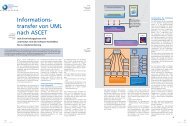
<strong>UML</strong>-<strong>to</strong>-<strong>ASCET</strong><br />
<strong>Information</strong> <strong>Transfer</strong><br />
Supporting all development phases from software<br />
architecture through implementation<br />
A core element of the transmission control software development process is the software<br />
continuity spanning the range from initial architecture design through implementation.<br />
This article discusses the manner in which fine-tuned <strong>to</strong>ols support each development phase<br />
while ensuring the consistency of the development process.<br />
T he<br />
increasing size and complexity<br />
of software complements call for<br />
description languages providing a<br />
higher level of abstraction. There is the<br />
old adage that a picture is worth a<br />
thousand words and, after assembler<br />
and C language programming, the<br />
trend points <strong>to</strong> graphical description<br />
languages.<br />
Therefore, in an effort <strong>to</strong> arrive at<br />
an efficient software development<br />
process, Robert Bosch GmbH deploys<br />
a precision-tuned combination of<br />
graphical design and development<br />
<strong>to</strong>ols in the development of software<br />
for transmission controls.<br />
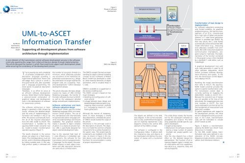
The software architecture or basic<br />
design is specified in <strong>UML</strong> (Ameos by<br />
Aonix), whereas the detailed design<br />
and the entry of implementation information<br />
are handled in <strong>ASCET</strong> by<br />
<strong>ETAS</strong>. The process au<strong>to</strong>matically transfers<br />
all of the required information<br />
from the <strong>UML</strong> model <strong>to</strong> <strong>ASCET</strong>. This<br />
transformation is handled by the<br />
aquin<strong>to</strong>s.M2M model converter <strong>to</strong>ol<br />
by model-<strong>to</strong>-model transformation<br />
specialist aquin<strong>to</strong>s (Figure 1).<br />
The results obtained in the various<br />
phases are subject <strong>to</strong> a fixed interrelation.<br />
This interdependency must not<br />
be lost, and it is therefore safeguarded<br />
by linking suitable <strong>to</strong>ols. In this way,<br />
high product quality is achieved and<br />
the number of recursions limited <strong>to</strong> a<br />
minimum, which effectively excludes<br />
any occurrence of the here<strong>to</strong>fore experienced<br />
inconsistencies (e.g., design<br />
documentation no longer matches the<br />
program code, etc.) caused by ”maverick<br />
developments” within individual<br />
development phases.<br />
This article discusses the basic design<br />
creation by means of <strong>UML</strong> (Unified<br />
Modeling Language), the transfer of<br />
the static software structure <strong>to</strong> <strong>ASCET</strong>,<br />
as well as the subsequent detailed<br />
design and software implementation.<br />
Software architecture and basic<br />
software subsystem design<br />
Robert Bosch GmbH uses the Unified<br />
Modeling Language (<strong>UML</strong>) in its transmission<br />
control projects. The use of<br />
this standardized and internationally<br />
recognized description language prevents<br />
misunderstandings and ensures<br />
readability. The graphical notation<br />
makes it possible <strong>to</strong> depict complex<br />
situations in a clearly structured manner.<br />
<strong>UML</strong> is specifically designed for<br />
object-oriented development tasks.<br />
Due <strong>to</strong> the required high level of<br />
C code efficiency in embedded realtime<br />
systems, the software for the<br />
transmission control is programmed in<br />
C language. For this reason, the possibilities<br />
inherent in both object orientation<br />
and <strong>UML</strong> description elements<br />
are used only <strong>to</strong> a limited extent.<br />
Figure 1:<br />
Phases of software<br />
development.<br />
Figure 2:<br />
<strong>UML</strong> class diagram.<br />
The OMOS concept (German acronym<br />
standing for object-oriented modeling<br />
concept for ECU software) of Robert<br />
Bosch GmbH was developed in order<br />
<strong>to</strong> utilize essential elements of object<br />
orientation, and <strong>to</strong> visualize these in<br />
C code.<br />
OMOS is available as a supplement in<br />
the Ameos modeling <strong>to</strong>ol.<br />
The OMOS concept is based on two<br />
major strategies:<br />
• Handling and configuration of software<br />
variants<br />
• Linkage between basic design and<br />
detailed design/implementation (e.g.,<br />
mapping object-oriented methods<br />
<strong>to</strong> C language by means of C code<br />
frame generation)<br />
Although the manner of implementation<br />
of these strategies is briefly<br />
described below, a detailed discussion<br />
of OMOS would exceed the scope of<br />
this article.<br />
Inheritance is the principle used in<br />
the description of variants. The objective<br />
is <strong>to</strong> model the common software<br />
components for a variety of projects in<br />
the parent class. The project-specific<br />
components are modeled in the child<br />
class. As shown in Figure 2, this stylistic<br />
device is also used <strong>to</strong> hide entire<br />
functions (<strong>to</strong> accommodate a variety<br />
of project requirements).<br />
SW System Architecture<br />
Architecture/Basic Design<br />
of Software Subsystem<br />
Detail Design<br />
of Software Subsystem<br />
<strong>ASCET</strong> Edi<strong>to</strong>r<br />
«1-Class»<br />
CL_TSiCnr<br />
«1-Class»<br />
CL_TSiDhl<br />
«1-Class»<br />
CL_TSiFo<br />
«1-Class»<br />
CL_TSiHil<br />
Partial Object Diagram ----><br />
Software Structuring<br />
Ameos<br />
Implementation + Code Generation<br />
of Software Subsystem<br />
«1-Class»<br />
CL_TSi_Bas<br />
«1-Class»<br />
CL_TSiHot<br />
«1-Class»<br />
CL_TSiWu<br />
«1-Class»<br />
CL_TSiWtr<br />
«1-Class»<br />
CL_TSiStgo<br />
The objects are defined in the <strong>UML</strong><br />
class diagram. In the current example,<br />
this is a class, and therefore the objects<br />
are not explicitly represented. Class<br />
diagrams comprise the central <strong>UML</strong><br />
element of the OMOS concept.<br />
The software is configured in the<br />
Configuration Edi<strong>to</strong>r. It defines both<br />
the originating class and objects <strong>to</strong><br />
be instantiated, and defines the association<br />
of classes with a (cus<strong>to</strong>mer)<br />
project.<br />
Transformation<br />
of Result of Basic<br />
Design/Formulation<br />
of Transformation<br />
Rules<br />
«1-Class»<br />
CL_TSiStgo<br />
«1-Class»<br />
CL_TSiStgo_Bas<br />
-bActv : bool<br />
-sDet: uint8<br />
-bDwnShft21: bool<br />
-ctDwnShft21: uint8<br />
-swtPlrTab_C: bool<br />
-tTraMax_C: uint8<br />
-rAccPedCst_C: uint8<br />
-drAccPedRngB_C:<br />
sint16<br />
-rAccPedRngA_C: uint8<br />
-rAccPedRngB_C: uint8<br />
-nTosRngA_C: uint16<br />
-nTosRngB_C: uint16<br />
-ctDwnShft21_C: uint8<br />
+CalcSituation()<br />
+Is_bActv() : bool<br />
«1-Class»<br />
CL_TloTra<br />
«1-Class»<br />
CL_TloTcp<br />
«1-Class»<br />
CL_TloPed<br />
«1-Class»<br />
CL_TloW<br />
Inheritance Diagram ----><br />
Representation of Variants.<br />
The CL_TSiStgo_Bas<br />
class can be removed<br />
through configuration.<br />
This initial phase creates the foundation<br />
for the subsequent software expandability<br />
and variance. The following<br />
properties provide specific support<br />
<strong>to</strong> developers:<br />
• Graphical description<br />
• Mechanisms for software characterized<br />
by a large number of variants<br />
(multiple use, project-specific variations)<br />
Only the class diagram has a direct<br />
effect on the detailed design/implementation.<br />
The function of all remaining<br />
diagram types is merely one<br />
of a descriptive and thus supplementary<br />
nature (e.g., sequence, state, and<br />
activity diagrams).<br />
Transformation of basic design <strong>to</strong><br />
implementation<br />
For software subsystems possessing<br />
only limited suitability for graphical<br />
programming (e.g., the memory management<br />
of an ECU, characterized<br />
by its high ratio of tables and pointer<br />
systems), a C code frame generation<br />
function is provided (see OMOS). By<br />
their very nature, the C code frames<br />
au<strong>to</strong>matically contain all essential <strong>UML</strong><br />
model information (e.g., measuring<br />
and calibration variables from attributes,<br />
INCLUDE instructions based on<br />
communication interrelations, program<br />
rumps for methods). The implementation<br />
of the function contained<br />
in the program rumps is then handled<br />
by a standard C code edi<strong>to</strong>r, such as<br />
CodeWright.<br />
A graphical development <strong>to</strong>ol with<br />
au<strong>to</strong> code generation is used for all<br />
other software subsystems, which<br />
further increases software development<br />
efficiency and quality. To this<br />
end, the transmission control department<br />
deploys <strong>ASCET</strong>.<br />
Handling the model transformation<br />
from <strong>UML</strong> <strong>to</strong> <strong>ASCET</strong>, the aquin<strong>to</strong>s.<br />
M2M model converter provides the<br />
option <strong>to</strong> specify transformation rules.<br />
The transmission control dept. is<br />
currently working on mapping the<br />
<strong>UML</strong>/OMOS models <strong>to</strong> <strong>ASCET</strong> V5.1.<br />
Because the consistent use of classes<br />
was not possible at the time of the<br />
pilot phase, the mapping process uses<br />
only modules in <strong>ASCET</strong>. The root<br />
cause originated in an internal <strong>to</strong>ol for<br />
the management of measurement and<br />
application variables.<br />
To gather experiences with regard <strong>to</strong><br />
the development process, the initial<br />
version is designed <strong>to</strong> serve as a pro<strong>to</strong>type.<br />
In the future, transformation<br />
rules will be extended <strong>to</strong> include<br />
<strong>ASCET</strong> classes as well.<br />
Figure 3 depicts a transformation<br />
aided by the M2M <strong>to</strong>ol. <strong>ASCET</strong> modeling<br />
occurs in modules.<br />
For the <strong>UML</strong> model classes, transformation<br />
rules were defined in consideration<br />
of the OMOS concept.<br />
Mapping includes all entity, communications,<br />
and inheritance relations.<br />
■➔<br />
25<br />
2007.1 RT
Figure 3:<br />
Transformation using<br />
aquin<strong>to</strong>s.M2M <strong>to</strong>ol.<br />
Figure 4:<br />
Excerpt from<br />
Architecture/Basic<br />
Design of ”Speed<br />
Selection” software<br />
subsystem.<br />
26<br />
RT 1.2007<br />
«1-Class»<br />
CL_FZGG<br />
«1-Class»<br />
CL_FZGG_KOMP<br />
«1-Class»<br />
CL_TDpDyn<br />
«1-Class»<br />
CL_TDpDyn_Bas<br />
-idRdoAct : uint8<br />
+GetGearReq( xGear:uint8 ) : uint8<br />
TDpDynDUsp<br />
TDpDynUsp<br />
TDpDynDsp<br />
«N-Class»<br />
CL_TDpDynTab<br />
-idAct : uint8<br />
-xCtlTab_C : uint8<br />
«1-Class»<br />
CL_SIWA<br />
«1-Class»<br />
CL_SIWA_CUST<br />
Ameos<br />
«RAM_Groesse» -FWA : uint8<br />
«RAM_Groesse» -CMO : uint8<br />
«Kennwert» -HDK : uint8<br />
«Kennwert» -CMOMIN : uint8<br />
«Kennlinie» -ECMO : uint16<br />
+IstWarmlauf( uint8 )<br />
+IstWaBew( uint8 )<br />
+ErmittleWarmlauf()<br />
+DetermineWarmUp()<br />
+ExitCondition( uint8 )<br />
<strong>ASCET</strong><br />
+IsActive( idSp:uint8 ) : bool<br />
+Reset()<br />
«1-Class»<br />
CL_MOT_LL<br />
«1-Class»<br />
CL_FSIT<br />
XMI-Interface<br />
COM API<br />
«1-Class»<br />
CL_MOT<br />
«1-Class»<br />
CL_MOT_AHK<br />
«1-Class»<br />
CL_MOT_ERW<br />
«1-Class»<br />
CL_FSIT_DEV<br />
«1-Class»<br />
CL_TloTra<br />
«1-Class»<br />
CL_TRcAdm<br />
The implementation by means of<br />
<strong>ASCET</strong> is carried out with the use of<br />
several useful segments of the <strong>UML</strong><br />
model (selection of individual classes).<br />
The selected classes are termed reference<br />
classes, and they are marked<br />
accordingly in the <strong>UML</strong> model. Because<br />
the inheritance principle is unknown<br />
in <strong>ASCET</strong>, inheritance relations<br />
are subject <strong>to</strong> the following rule cited<br />
here as an example:<br />
”Proceed through the inheritance tree<br />
of the reference class <strong>to</strong> the so-called<br />
parent class, and collect all of the<br />
attributes <strong>to</strong> be inherited. The attributes<br />
thus collected are then transferred<br />
<strong>to</strong> the reference class.”<br />
Multiple instantiations with <strong>ASCET</strong><br />
As discussed earlier, the use of <strong>ASCET</strong><br />
classes in transformation is not yet<br />
supported. To facilitate the use of<br />
multiple instantiations (N-classes) in<br />
<strong>ASCET</strong>, work on the extension of the<br />
transformation guideline is ongoing.<br />
The extension is depicted in the class<br />
diagram in Figure 4. The diagram describes<br />
interrelations between classes<br />
and defines the names and numbers<br />
of instantiations.<br />
Readily recognizable are the three<br />
instantiations of the CL_TDpDynTab<br />
class as well as the communications<br />
interrelations with adjacent classes.<br />
As depicted in Figure 5, the multiple<br />
instantiation must find its counterpart<br />
in <strong>ASCET</strong> if the detail design and<br />
implementation are <strong>to</strong> be effected.<br />
To this end, the CL_TDpDynTab class<br />
is created in <strong>ASCET</strong>. The methods and<br />
attributes are adopted from the<br />
class diagram. As shown in Figure 6,<br />
the three instantiations of the<br />
CL_TDpDynTab class are created in<br />
the form of local attributes in the<br />
CL_TDpDyn_Bas class.<br />
Detailed design, implementation,<br />
and au<strong>to</strong>matic code generation<br />
Both the detailed design and implementation<br />
are carried out with the aid<br />
of graphical programming – one of the<br />
core elements in <strong>ASCET</strong>. The block<br />
diagram frames for graphical programming<br />
are provided as a result of<br />
the transformation. Figure 5 depicts<br />
an example of graphical programming<br />
in the block diagram. The implementation<br />
information for measurement<br />
and calibration variables (attributes)<br />
is completed in <strong>ASCET</strong>. At this point,<br />
the au<strong>to</strong>matic code generation can be<br />
started.<br />
The code generation is handled by<br />
<strong>ASCET</strong>’s standard code genera<strong>to</strong>r with<br />
cus<strong>to</strong>mer-specific adaptations. The<br />
code genera<strong>to</strong>r writes well-defined<br />
C code. At the transmission control<br />
department, one C file is generated<br />
for each class, and optimizations for<br />
1-classes are au<strong>to</strong>matically considered<br />
by <strong>ASCET</strong>. The executable program<br />
(HEX file) is generated outside of<br />
<strong>ASCET</strong> by means of the standard development<br />
environment.<br />
The measurement and calibration<br />
variables (attributes) must be measurable<br />
by a calibration <strong>to</strong>ol. For the modules<br />
and classes, <strong>ASCET</strong> generates<br />
associated files in accordance with the<br />
MSRSW standard. The same standard<br />
also contains implementation information<br />
for C code. This information<br />
permits the generation of c and h files.<br />
In this way, the measurement and calibration<br />
variables are made available in<br />
the application program (Figure 7).<br />
<strong>ASCET</strong> and its code generation is<br />
successfully deployed in several divisions<br />
of Robert Bosch GmbH.<br />
Summary<br />
The development process under discussion<br />
provides developers with the<br />
capability <strong>to</strong> graphically describe their<br />
software from the point of designing<br />
the architecture <strong>to</strong> final implementation.<br />
Variant handling, which is so<br />
essential in the au<strong>to</strong>mobile industry,<br />
is integrated in the process. Each process<br />
phase makes use of specifically<br />
optimized <strong>to</strong>oling. Because the information<br />
belonging <strong>to</strong> individual development<br />
phases is permanently interlinked,<br />
it is not possible for these<br />
phases <strong>to</strong> become dissimilar or suffer<br />
from ”maverick development”. As part<br />
of the design process, the graphical<br />
<strong>UML</strong> notation unambiguously describes<br />
even complex circumstances.<br />
<strong>ASCET</strong> makes it possible <strong>to</strong> also perform<br />
function development at the<br />
graphical level. At the same time, the<br />
graphical modeling of algorithms<br />
provides an excellent documentation.<br />
The deployment of the described development<br />
process prevents recursions<br />
and significantly increases development<br />
efficiency.<br />
Three instantiations of<br />
CL_TDpDynTab class<br />
CL_TDpDynTab<br />
PAR_idTyp<br />
PAR_idRdo IsActive<br />
Usp<br />
CL_TDpDynTab<br />
PAR_idTyp<br />
PAR_idRdo IsActive<br />
DUsp<br />
CL_TDpDynTab<br />
PAR_idTyp<br />
PAR_idRdo IsActive<br />
Dsp<br />
Figure 5:<br />
CL_TDpDynTab<br />
class in <strong>ASCET</strong><br />
with Detail Design/<br />
Implementation.<br />
Figure 6:<br />
Local instantiations<br />
of CL_TDpDynTab class.<br />
Figure 7:<br />
Excerpts from<br />
<strong>ASCET</strong>-generated<br />
files for build<br />
process.<br />
C Language File MSRSW File<br />
27<br />
2007.1 RT