Product Families - MSC Vertriebs GmbH
Product Families - MSC Vertriebs GmbH
Product Families - MSC Vertriebs GmbH

You also want an ePaper? Increase the reach of your titles
YUMPU automatically turns print PDFs into web optimized ePapers that Google loves.
<strong>Product</strong> Overview 2009<br />
8 bit AVR RISC MCUs<br />
■ 1 - 256 kBytes ISP Flash / E 2<br />
■ picoPower TM<br />
The<br />
World of<br />
Microcontrollers<br />
■ On-Chip Debugging Interface<br />
■ LCD Drivers<br />
■ CAN Interface<br />
■ USB Interface<br />
<strong>MSC</strong> - Distributor of<br />
®
2<br />
Atmel’s RISC MCU <strong>Families</strong><br />
Welcome to the World of Atmel’s RISC microcontrollers<br />
Join the big world of Atmel’s 8-bit and 32-bit RISC MCU families!<br />
From lowest cost ATTINY, high performance ATMEGA or new XMEGA family, Atmel’s 8-bit AVR portfolio covers devices from<br />
16 MIPS up 32 MIPS with pin counts from 8 up to 100 pins. Flash memories from 1K up to 256K are available.<br />
Atmel’s new AVR32 32-bit core is introduced in UC3 fl ash based derivates and in the AP7 application processor products. A lot<br />
of intelligent technologies make this core the winner in performance and power consumption over all existing 32-bit technologies.<br />
Here, will fi nd fl ash based products up to 512K with a lot of communication interfaces as well as high performance processors<br />
with MMU and cashes especially for embedded Linux, which is supported directly by Atmel.<br />
Atmel’s SAM ARM ® families cover a broad range of products from fl ash based SAM7 and SAM9 MCU products as well as SAM9<br />
MPUs for Windows CE ® and embedded Linux.<br />
A rich set of communication peripherals, lots of smart implementations and different available development tools and operating<br />
systems in the market make this products very successful. In 2009 Atmel will introduce fi rst SAM3 ® Cortex-M3 Flash families,<br />
that will combine high MIPs power with low power consumption.<br />
Migration<br />
Both AVR32 and SAM ARM ® use many common peripherals,<br />
enabling migration between the families much more easier,<br />
than jumping between different MCU technology. Furthermore<br />
advanced XMEGA peripherals are included in Atmel’s<br />
32-bit MCUs.<br />
Common tools<br />
Common peripherals<br />
Atmel’s RISC architectures<br />
Tools<br />
AVR32, AVR and XMEGA products come with dedicated free<br />
of charge AVR Studios and can be debugged with JTAGICE-<br />
MK2. So feel free to start with AVR, enlarge your application to<br />
XMEGA and proceed to AVR32 MCUs with the same set of tools.
Family Overview<br />
ATMEL´s AVR ® microcontroller have a true 8-bit RISC core running single cycle<br />
instructions and a well-defi ned I/O structure that limits the need for external components.<br />
AVR ® Flash microcontrollers operate with clock rates up to 32 MHz, achieving close<br />
to 32 MIPS. With 32 general purpose registers, the AVR ® delivers unmatched performance<br />
and fl exibility, especially when you program in high-level languages, like<br />
C, Pascal or Basic.<br />
The AVR ® RISC core is a Havard architecture with separate buses and address<br />
spaces for program and data memories, load and store operations and a 32 byte<br />
register fi le. The AVR ® has up to 133 instructins which are either 16/32 bit wide and<br />
about 80% of these are executed in a single cycle.<br />
AVR ® Flash microcontrollers are a large family of processors that share a single<br />
core architecture. This makes it easy to reuse code in your next project and you can<br />
use the same development tool set for all AVR ® microcontrollers.<br />
The wide range of available devices from 8-pin / 1 KB Flash memory to 100-pin /<br />
256 KB Flash memory and the high integration level make it an ideal choice to low<br />
cost, small dimension to medium range applications from small actuators/sensors<br />
up to complex applications.<br />
The AVR ® devices are available in 3 families (tiny, mega and Xmega) plus different<br />
Application Specifi c Standard <strong>Product</strong>s (ASSP) like USB, PWM, LCD or CAN devices.<br />
The AVR ® mega and Xmega devices support self-programming fl ash, allowing<br />
them to upgrade their own fi rmware by using any existing communication interface.<br />
Lock-bits protect your code from being inappropriately read or copied.<br />
AVR Studio ® is a free-of-charge professional Integrated Development Environment<br />
(IDE) for writing and debugging AVR ® applications. It could handle all available Atmel<br />
tools like the starter kits or in-circuit-emulators. Nearly all AVRs devices have<br />
an on-chip debug interface (debugWIRE or JTAG).<br />
AVR ® Flash microcontrollers have up to six different sleep modes. Software controlled<br />
frequency makes it possible to use maximum speed when needed, saving power the rest<br />
of the time. High code density ensures that a minimum of instructions and clock cycles<br />
are needed to execute a task, thereby reducing the power consumption signifi cantly.<br />
3
4<br />
Temporary<br />
Buffer<br />
128 Byte RAM<br />
Segment RAM is not part<br />
of the internal Data RAM<br />
128 Byte Segment<br />
128 Byte Segment<br />
128 Byte Segment<br />
128 Byte Segment<br />
128 Byte Segment<br />
128 Byte Segment<br />
128 Byte Segment<br />
128 Byte Segment<br />
128 Byte Segment<br />
128 Byte Segment<br />
Boot Block Application Block<br />
Self-Programming Flash<br />
With on-chip in-system programmable Flash and EEPROM, the AVR is a perfect<br />
choice in order to optimise cost and offer lowest time-to-market. The core of the<br />
MEGA Family is also able to reprogram (self-program) the fl ash with the application<br />
software. To do that, the Flash is divided into individual erase/programmable<br />
small segments of 128 or 256 Bytes. The segments are joined together to<br />
an application block and a boot block. The core is able to execute instructions in<br />
the up to 8 kByte boot block while segments in the application block are erased or<br />
programmed. In addition the boot block has its own interrupt vector table and the<br />
reset vector can be confi gured (by a fuse bit) to point to the beginning of the boot<br />
block instead of the application block. As a result an application specifi c boot loader<br />
can be programmed with real time characteristics. An example of a boot loader is<br />
described in the application note AVR109 which can be downloaded free of charge<br />
at www.atmel.com. The in-system programmable Flash makes it easy to program<br />
your boot loader in a new device which is usually shipped without a boot loader.<br />
JTAG Interface<br />
All AVRs of the MEGA family with 16 kByte and more Flash memory have a JTAG<br />
interface for debugging, in-system testing and in-system programming. When the<br />
JTAG interface is used together with AVR Studio and the AT90JTAGICE for debugging<br />
you are able to set an unlimited number of breakpoints in your source code<br />
to do single stepping a.s.o. In addition it is possible to set data breakpoints in the<br />
I/O or data memory address space. When the program accesses this dedicated I/O<br />
or data memory addresses (for example variables or the end of a stack) program<br />
execution is stopped. When used for in-system testing you are able to use the<br />
boundary-scan register to individually confi gure each I/O pin for a maximum of testing<br />
effi ciency in your PCB end test. In addition to this you can use the JTAG interface<br />
to in-system program the devices with your PCB end test equipment. No additional<br />
programming voltage is necessary for JTAG, SPI or Self-Programming.<br />
DebugWIRE Interface<br />
DebugWIRE is a One-wire, bi-directional interface for all new AVRs with 16 kByte<br />
and less fl ash memory. It enables On-Chip debugging at the real target device.<br />
This debugging interface offers full execution and program fl ow control. In addition<br />
this presents an unlimited number of breakpoints, adjustment of I/O pins, monitor<br />
functionality and programming of nonvolatile memories. Additional pins are not<br />
required as the reset pin is used for connectivity.
<strong>Product</strong> <strong>Families</strong><br />
With a wide variety of package and performance and performance options, AVR<br />
controllers give you the versatility to meet any challenge and capture any opportunity.<br />
Different product families makes it easier for you to fi nd the best fi tting device.<br />
tiny AVR<br />
The tinyAVR devices are general purpose fl ash-based microcontroller. They offer an<br />
unrivaled combination of price, performance and fl exibility. The same Flash-based<br />
microcontroller can be used for design, prototype evaluation and volume production<br />
resulting in cost reduction by minimizing inventory. The tinyAVRs are available from<br />
1K bytes to 8K bytes Flash program memory in very small packages.<br />
Features<br />
■ Single cycle 8-bit RISC architecture<br />
■ high performance<br />
■ low power consumption<br />
■ internal RC Oscillator<br />
■ integrated EEPROM<br />
■ A/D Converter<br />
■ On-Chip 8-bit/16-bit timers and Watchdog<br />
■ High Frequency PWM with PLL<br />
■ On-Chip debug interface (debugWIRE)<br />
Mega AVR<br />
The megaAVR controllers are general purpose microcontroller with up to 256K Bytes<br />
self programming Flash Memory, 4K Bytes SRAM and EEPROM.<br />
The megaAVR devices are developed for applications that need to store a large<br />
amout of program code. The megaAVR offers substantial program and data<br />
memories, and performance approaching 1 MIPS per MHz. The megaAVR delivers<br />
the power of self-programmability for fast, secure, cost-effective remote upgrades.<br />
Features<br />
■ Single cycle 8-bit RISC architecture<br />
■ Complete Family with 4K to 256K Bytes Flash<br />
■ High performance<br />
■ Self programming Flash memory with boot block<br />
■ 10-bit A/D converter<br />
■ 8 x 8 Hardware Multiplier<br />
■ integrated EEPROM<br />
■ internal RC Oscillator<br />
■ USART, SPI and TWI compliant serial interfaces<br />
■ On-Chip 8-bit/16-bit timers and Watchdog<br />
■ On-Chip debug through JTAG or (debugWIRE)<br />
■ Extended voltage range<br />
■ Package range from 28-pin to 100-pin in DIP, TQFP and MLF types<br />
CAN AVR<br />
The CAN AVR family offers high performance together with extended CAN (Controller<br />
Area Network) capabilities. The devices are perfectly suited for many CAN networking<br />
and industrial applications, including factory and building automation, medical<br />
equipment, marine networking and print media. The fi rst available device features<br />
128K bytes Flash memory. This large amount of memory together with a high processing<br />
speed allows to operate higher layer protocol stack (CANopen, DeviceNet or J1939).<br />
Features<br />
■ High Performance 1 MIPS per MHz<br />
■ V2.0A/V2.0B CAN controller with 15 independent message objects<br />
■ Highly fl exible In-Application Programming capability via CAN, UART or SPI<br />
5
6<br />
<strong>Product</strong> <strong>Families</strong><br />
LCD AVR<br />
The LCD AVR devices have a integrated LCD driver with automatic contrast control.<br />
Designed for maximum fl exibility and highest possible integration, the LCD AVR<br />
family of high performance, low-power microcontrollers includes everything you<br />
need for human interface. The feature set includes keyboard interrupts, visual LCD<br />
driver with contrast control and interrupts for input switches.<br />
PWM AVR<br />
The PWM AVR family is specially designed for Lamp ballast and Motor Control<br />
applications.<br />
Developed together with the industry leading lamp ballast manufactures, Atmel‘s<br />
PWM AVR microcontroller are optimizied for Linear and Dimmable Flurescent<br />
tubes, as well as High Density Discharge (HID) ballasts. Their dedicated features<br />
allow for truly intelligent lighting networks, resulting in energy savings.<br />
The PWM AVRs are dedicated for motor control applications by their exceeding<br />
PWM part as well.<br />
USB AVR<br />
The AT90USB microcontrollers are designed to address the varied requirements of<br />
embedded applications needing USB connectivity.<br />
Four AVRs are available: the AT90USB1286 and AT90USB1287 have 128 Kbytes of<br />
In-System Programmable (ISP) Flash, 8 Kbytes of RAM and 4 Kbytes of EEPROM.<br />
The AT90USB646 and AT90USB647 are identical but with half the memory size.<br />
The AT90USB1286 and AT90USB646 and have USB interface for applications needing<br />
to communicate with USB host.<br />
The AT90USB1287 and AT90USB647 comply with the USB On-The-Go (OTG) standard<br />
for use as Dual Role Devices (DRD) in applications operating as either host or<br />
function on the USB. The USB host capability is key to embedded devices needing to<br />
communicate without PC intervention.<br />
picoPowerTM AVR<br />
The picoPowerTM AVR devices are designed to achieve even lower power comsumption<br />
with the same performance. The picoPowerTM technology incorporate a<br />
number of techniques for lower power consumption in sleep and active mode.<br />
The key elements are:<br />
■ True 1.8 Volt Supply Voltag<br />
■ Minimized Leakage Current<br />
■ Sleeping Brown Out Detection<br />
■ Ultra Low Power 32 kHz Crystal Oscillator<br />
■ Digital Input Disable Register<br />
■ Clock Gating<br />
■ Flash Sampling<br />
picoPowerTM AVRs will be identifi ed with a “P” added on the device name:<br />
i.e. ATmega169 becomes ATmega169P.
AVR ® Xmega<br />
Response Time<br />
100% CPU usage<br />
Battery Level<br />
Conventional MCU<br />
Conventional MCU<br />
XMEGA with Event System<br />
2nd generation<br />
picoPower TM<br />
Application complexity<br />
without DMA<br />
with DMA<br />
Communication rate<br />
picoPower technology<br />
Durability<br />
Atmel ® has introduced the new Xmega TM family.<br />
AVR Xmega microcontrollers have the same acclaimed characteristics as the<br />
established AVR devices, and operates from just 1.6 volt with up to 32 MIPS at 32<br />
MHz. Memory size range from 16 to 384 KB of Flash and they come in 44- to 100-pin<br />
packages. The Xmega devices are general purpose microcontrollers well suited for<br />
a variety of applications including audio systems, ZigBee ® , power tools, medical ,<br />
board controllers, networking, metering, optical transceivers, motor control, white<br />
goods and any battery powered product.<br />
With an impressive list of features and a drastically increased peripheral throughput,<br />
the CPU can spend less time handling peripherals and even more time in sleep mode.<br />
AVR CPU<br />
32 MHZ<br />
1.6 Volt<br />
12-bit Analog<br />
ADC and DAC<br />
2 Msps / 1 Msps<br />
Memories<br />
Flash, EEPROM, SRAM<br />
16-bit Timers<br />
Real-Time Counter<br />
Timer / Counters<br />
DNA Controller<br />
4 Channels<br />
Communicaton<br />
USART, SPI, TWI<br />
Event System<br />
Interrupt Controller<br />
Cryptography<br />
AES and DES<br />
Event System<br />
Like a refl ex in the human body, the innovative Xmega Event System enables interperipheral<br />
communication without CPU or DMA usage. This ensures 100% predictable<br />
and short response time. Up to 8 simultaneous events or interrupt conditions<br />
in the peripherals can automatically start actions in other peripherals.<br />
DMA Controller<br />
A 4-channel DMA Controller enables fast, CPU independent data transfer that<br />
signifi cantly boosts performance. The DMA Controller in Xmega handles transfers<br />
between all combinations of data memories and peripherals.<br />
Real 12-bit ADC and DAC<br />
For high analog accuracy the Xmega features high-speed 12-bit analog peripherals.<br />
Capable of up to 2 Msps, Xmega’s ADCs deliver the fastest sample rate and<br />
most accurate result compared to conventional MCUs. Since XMEGA also features<br />
two 12-bit digital-to-analog converters (DAC) with up to 1 Msps and four advanced<br />
analog comparators, XMEGA microcontrollers have leading analog integration.<br />
Compatibility and tools<br />
Xmega uses the same instruction set as existing AVR products, and code can<br />
easily be reused. All Xmega family members are pin and 100% code compatible, and<br />
designers can easily reuse both source and binary code in all projects.<br />
Xmega is supported by the easy-to-use tool chain already existing for AVR devices,<br />
and Compilers and development tools platforms are the same for all AVR microcontrollers.<br />
Programmable Multilevel Interrupt Controller<br />
All peripherals have software selectable interrupts and different interrupt vectors.<br />
Xmega has high, medium and low level interrupt which are user selectable for each<br />
interrupts source<br />
Second Generation picoPower TM<br />
Atmel’s picoPower technology have proven to be the industry leader in low power<br />
designs. With the 2nd generation picoPower technology, Xmega MCUs run a Real-<br />
Time Counter, Watchdog Timer and Brown-out Detector with only 2 µA current<br />
consumption.<br />
The Xmega also incorporates true 1.6 volt operation and elements like dynamic<br />
clock switching, and frequency scaling for optimal power management.<br />
7<br />
AVR<br />
32 M<br />
1.6
8<br />
Device Overview tiny<br />
AVR<br />
tiny AVR<br />
Device<br />
ATTINYs in 8-Pin Package<br />
ATTINY13V<br />
ATTINY13<br />
Flash in Kbyte<br />
RAM<br />
E 2<br />
I/Os<br />
10Bit ADC<br />
Serial I/Os<br />
8Bit Timer<br />
1 64 64 max. 6 4 1 with<br />
2 Comp.<br />
2 PWM<br />
Chan.<br />
ATTINY13A-xx 1 64 64 max. 6 4 USI 1 with<br />
2 Comp.<br />
2 PWM<br />
ATTINYx5 Family in 8-Pin Package<br />
ATTINY25V-10xx 2 128 128 max. 6 4 USI 2 with<br />
ATTINY25-20xx<br />
2 Comp.<br />
2 PWM<br />
Chan.<br />
ATTINY45V-10xx<br />
ATTINY45-20xx<br />
ATTINY85V-10xx<br />
ATTINY85-20xx<br />
4 256 256 max. 6 4 USI 2 with<br />
2 Comp.<br />
2 PWM<br />
Chan.<br />
8 512 512 max. 6 4 USI 2 with<br />
2 Comp.<br />
2 PWM<br />
Chan.<br />
ATTINYx4 Family in 14-Pin Package<br />
ATTINY24V-10xx 2 128 128 12 8 USI 1 with<br />
ATTINY24-20xx<br />
2 Comp.<br />
2 PWM<br />
Chan.<br />
ATTINY44V-10xx<br />
ATTINY44-20xx<br />
ATTINY84V-10xx<br />
ATTINY84-20xx<br />
4 256 256 12 8 USI 1 with<br />
2 Comp.<br />
2 PWM<br />
Chan.<br />
8 512 512 12 8 USI 1 with<br />
2 Comp.<br />
2 PWM<br />
Chan.<br />
ATTINYs in 20-Pin Package<br />
ATTINY2313V-10xx 2 128 128 max. 18 US-<br />
ART,<br />
ATTINY2313-20xx<br />
USI<br />
1 with<br />
2 Comp.<br />
2 PWM<br />
Chan.<br />
ATTINYx61 Family in 20-Pin Package<br />
ATTINY26L-8xx<br />
2 128 128 13 to 16 11 USI 1 + 1 with<br />
ATTINY26-16xx<br />
2 Comp.<br />
2 PWM Chan.<br />
ATTINY261V-10xx<br />
ATTINY261-20xx<br />
ATTINY461V-10xx<br />
ATTINY461-20xx<br />
ATTINY861V-10xx<br />
ATTINY861-20xx<br />
2 128 128 max. 16 11 USI 1 with<br />
3 Comp.<br />
3 PWM Chan.<br />
4 256 256 max. 16 11 USI 1 with<br />
3 Comp.<br />
3 PWM Chan.<br />
8 512 512 max. 16 11 USI 1 with<br />
3 Comp.<br />
3 PWM Chan.<br />
ATTINY167-15xx 16 512 512 16 11 SPI<br />
USI<br />
LIN<br />
ATTINYx8 Family in 32-Pin Package<br />
ATTINY48-xx 4 256 64 max.28 max.8 SPI,<br />
TWI<br />
ATTINY88-xx 8 512 64 max.28 max.8 SPI,<br />
TWI<br />
No responsibility is taken for the correctness of the informations<br />
1 with<br />
1 Comp.<br />
1 PWM<br />
16Bit Timer<br />
1 with 2 Comp.<br />
2 PWM Chan.<br />
1 with 2 Comp.<br />
2 PWM Chan.<br />
1 with 2 Comp.<br />
2 PWM Chan.<br />
1 with 1 Cap.<br />
2 Comp. 2 PWM<br />
Chan.<br />
1 with 2 Comp.<br />
2 PWM Can.<br />
1 with 2 Comp.<br />
2 PWM Chan.<br />
1 with 2 Comp.<br />
2 PWM Chan.<br />
1 with<br />
2 Comp.<br />
2 PWM<br />
1 with 2 Comp. 1 with 1 Cap.<br />
2 Comp. 2 PWM<br />
Chan.<br />
1 with 2 Comp. 1 with 1 Cap.<br />
2 Comp.<br />
2 PWM Chan.<br />
Extended Memory<br />
Interface<br />
Sub Clock<br />
Analog Comp.<br />
On-Chip RC Osc.<br />
in MHz<br />
Brown-Out Det.<br />
Max. Clock<br />
@Voltage Range<br />
✔ 0.128, 4.8, 9.6 ✔ 4MHz @ 1.8 to 5.5V<br />
10MHz @ 2.7 to 5.5V<br />
10MHz @ 2.7 to 5.5V<br />
20MHz @ 4.5 to 5.5V<br />
✔ 0.128, 4.8, 9.6 ✔ 0 - 4MHz @ 1.8 to 5.5V<br />
0 - 10MHZ @ 2.7 to 5.5V<br />
0 - 20MHz @ 4.5 to 5.5V<br />
✔ 6.4, 8 ✔ 4MHz @ 1.8 to 5.5V<br />
10MHz @ 2.7 to 5.5V<br />
10MHz @ 2.7 to 5.5V<br />
20MHz @ 4.5 to 5.5V<br />
✔ 6.4, 8 ✔ 4MHz @ 1.8 to 5.5V<br />
10MHz @ 2.7 to 5.5V<br />
10MHz @ 2.7 to 5.5V<br />
20MHz @ 4.5 to 5.5V<br />
✔ 6.4, 8 ✔ 4MHz @ 1.8 to 5.5V<br />
10MHz @ 2.7 to 5.5V<br />
10MHz @ 2.7 to 5.5V<br />
20MHz @ 4.5 to 5.5V<br />
✔ 8 ✔ 4MHz @ 1.8 to 5.5V<br />
10MHz @ 2.7 to 5.5V<br />
10MHz @ 2.7 to 5.5V<br />
20MHz @ 4.5 to 5.5V<br />
✔ 8 ✔ 4MHz @ 1.8 to 5.5V<br />
10MHz @ 2.7 to 5.5V<br />
10MHz @ 2.7 to 5.5V<br />
20MHz @ 4.5 to 5.5V<br />
✔ 8 ✔ 4MHz @ 1.8 to 5.5V<br />
10MHz @ 2.7 to 5.5V<br />
10MHz @ 2.7 to 5.5V<br />
20MHz @ 4.5 to 5.5V<br />
✔ 4, 8 ✔ 4MHz @ 1.8 to 5.5V<br />
10MHz @ 2.7 to 5.5V<br />
10MHz @ 2.7 to 5.5V<br />
20MHz @ 4.5 to 5.5V<br />
✔ 1, 2, 4, 8 ✔ 8MHz @ 2.7 to 5.5V<br />
16MHz @ 4.5 to 5.5V<br />
✔ 8 ✔ 4 MHz @ 1.8 to 5.5V<br />
10MHZ @ 2.7 to 5.5V<br />
10MHz @ 2.7 to 5.5V<br />
20MHz @ 4.5 to 5.5V<br />
✔ 8 ✔ 4MHz @ 1.8 to 5.5V<br />
10MHz @ 2.7 to 5.5V<br />
10MHz @ 2.7 to 5.5V<br />
20MHz @ 4.5 to 5.5V<br />
✔ 8 ✔ 4MHz @ 1.8 to 5.5V<br />
10MHz @ 2.7 to 5.5V<br />
10MHz @ 2.7 to 5.5V<br />
20MHz @ 4.5 to 5.5V<br />
✔ 8 ✔ 0 - 8MHZ @ 2.7 to 5.5V<br />
0 - 16MHz @ 4.5 to 5.5V<br />
✔ ✔ 0.128,8 ✔ 0 - 2MHz @ 1.8 to 5.5V<br />
0 - 6MHZ @ 2.7 to 5.5V<br />
0 - 12MHz @ 4.5 to 5.5V<br />
✔ ✔ 0.128,8 ✔ 0 - 2MHz @ 1.8 to 5.5V<br />
0 - 6MHZ @ 2.7 to 5.5V<br />
0 - 12MHz @ 4.5 to 5.5V
Starter-Kit<br />
In-Circuit-<br />
Emulator<br />
On-Chip<br />
Debugging<br />
Interface<br />
Automotive Spec.<br />
available<br />
ATSTK500 ATJTAGICE-MK2 debugWIRE DIL8<br />
SOP8<br />
MLF20<br />
ATSTK500 ATJTAGICE-MK2 debugWIRE TM DIL8<br />
SOP8<br />
MLF20<br />
MLF10<br />
ATSTK500 ATJTAGICE-MK2 debugWIRE ✔ DIL8<br />
SOP8<br />
MLF20<br />
ATSTK500 ATJTAGICE-MK2 debugWIRE ✔ DIL8<br />
SOP8<br />
MLF20<br />
ATSTK500 ATJTAGICE-MK2 debugWIRE ✔ DIL8<br />
MLF20<br />
ATSTK500 +<br />
ATSTK505<br />
ATSTK500 +<br />
ATSTK505<br />
ATSTK500 +<br />
ATSTK505<br />
Package<br />
ATJTAGICE-MK2 debugWIRE ✔ DIL14<br />
SOP14<br />
MLF20<br />
ATJTAGICE-MK2 debugWIRE ✔ DIL14<br />
SOP14<br />
MLF20<br />
ATJTAGICE-MK2 debugWIRE ✔ DIL14<br />
MLF20<br />
ATSTK500 ATJTAGICE-MK2 debugWIRE DIL20<br />
SOP20<br />
MLF20<br />
ATSTK500 DIL20<br />
SOP20<br />
MLF32<br />
ATSTK500 ATJTAGICE-MK2 debugWIRE ✔ DIL20<br />
SOP20<br />
MLF32<br />
ATSTK500 ATJTAGICE-MK2 debugWIRE ✔ DIL20<br />
SOP20<br />
MLF32<br />
ATSTK500 ATJTAGICE-MK2 debugWIRE ✔ DIL20<br />
SOP20<br />
MLF32<br />
ATSTK600 ATJTAGICE-MK2 debugWIRE TM ✔ SOIC-20<br />
TSSOP-20<br />
QFN-32<br />
ATSTK500 ATJTAGICE-MK2 debugWIRE DIL28<br />
TQFP32<br />
MLF32<br />
MLF28<br />
ATSTK500 ATJTAGICE-MK2 debugWIRE DIL28<br />
TQFP32<br />
MLF32<br />
MLF28<br />
Silicon Status<br />
Additional<br />
Features<br />
Mass <strong>Product</strong>ion Pin-Change Interrupt;<br />
Calibr. On-Chip Osc.<br />
Mass <strong>Product</strong>ion Pin-Change Interrupt<br />
sleeping BOD<br />
Mass <strong>Product</strong>ion Pin-Change Interrupt;<br />
On-Chip Temperature Sensor<br />
ADC with diff. Mode<br />
Mass <strong>Product</strong>ion Pin-Change Interrupt;<br />
On-Chip Temperature Sensor<br />
ADC with diff. Mode<br />
Mass <strong>Product</strong>ion Pin-Change Interrupt;<br />
On-Chip Temperature Sensor<br />
ADC with diff. Mode<br />
Mass <strong>Product</strong>ion Pin-Change Interrupt;<br />
On-Chip Temperature Sensor,<br />
ADC with diff. Mode<br />
Mass <strong>Product</strong>ion Pin-Change Interrupt;<br />
On-Chip Temperature Sensor,<br />
ADC with diff. Mode<br />
Mass <strong>Product</strong>ion Pin-Change Interrupt;<br />
On-Chip Temperature Sensor,<br />
ADC with diff. Mode<br />
Mass <strong>Product</strong>ion Calibr. On-Chip Osc.;<br />
Pin-Change Interrupt<br />
Mass <strong>Product</strong>ion Calibr. On-Chip Osc.;<br />
ADC with diff. Mode<br />
Pin-Change Interrupt<br />
Mass <strong>Product</strong>ion Pin-Change Interrupt<br />
On-Chip Temperature Sensor<br />
Mass <strong>Product</strong>ion Pin-Change Interrupt;<br />
Calibr. On-Chip Osc.<br />
On-Chip Temperature Sensor<br />
Mass <strong>Product</strong>ion Pin-Change Interrupt;<br />
Calibr. On-Chip Osc.<br />
On-Chip Temperature Sensor<br />
Samples in Q1/09 Operating Temperature up to<br />
150°C ;<br />
Hardware LIN<br />
Pin Compatible<br />
with<br />
tiny11<br />
ATtiny13<br />
ATTINY15<br />
ATTINY45<br />
ATTINY85<br />
ATTINY15<br />
ATTINY25<br />
ATTINY85<br />
ATTINY15<br />
ATTINY25<br />
ATTINY45<br />
ATTINY44<br />
ATTINY84<br />
ATTINY24<br />
ATTINY84<br />
ATTINY24<br />
ATTINY44<br />
ATTINY261<br />
ATTINY461<br />
ATTINY861<br />
ATTINY26<br />
ATTINY461<br />
ATTINY861<br />
ATTINY26<br />
ATTINY261<br />
ATTINY861<br />
ATTINY26<br />
ATTINY261<br />
ATTINY461<br />
Mass <strong>Product</strong>ion Pin-Change Interrupt ATTINY88<br />
Mass <strong>Product</strong>ion Pin-Change Interrupt ATTINY48<br />
5,3<br />
Pitch: 1,27<br />
9,0<br />
Pitch: 0,8<br />
7,0<br />
Pitch: 0,5<br />
Scale 1:1<br />
Dimensions in mm<br />
9,0<br />
12,8<br />
Pitch: 1,27<br />
Pitch: 0,5<br />
16,0<br />
Pitch: 0,8<br />
8,0<br />
5,0 Bottom View<br />
Pitch: 0,5<br />
12,0<br />
Pitch: 0,8<br />
5,0<br />
7,0<br />
9,0<br />
9,0<br />
10,4<br />
4,0 Bottom View<br />
Pitch: 0,5<br />
4,0<br />
12,0<br />
16,0<br />
SOP8<br />
SOP20<br />
SOP20<br />
MLF20<br />
MLF20<br />
MLF32<br />
MLF32<br />
TQFP32<br />
TQFP32<br />
MLF44<br />
TQFP44<br />
MLF64<br />
TQFP64<br />
9
10<br />
Device Overview mega (1)<br />
megaAVR<br />
Device<br />
Flash in Kbyte<br />
RAM in byte<br />
ATMEGAx8 Family in 32-Pin Package<br />
ATMEGA48(P)V-10xx 4 512 256 max.23 8 USART, SPI,<br />
ATMEGA48(P)-20xx<br />
TWI<br />
ATMEGA8L-8xx<br />
ATMEGA8-16xx<br />
ATMEGA88(P)V-10xx<br />
ATMEGA88(P)-20xx<br />
ATMEGA168(P)V-10xx<br />
ATMEGA168(P)-20xx<br />
EEPROM in byte<br />
I/Os<br />
10-Bit ADC<br />
Serial I/Os<br />
8 1K 512 max.23 8 USART, SPI,<br />
TWI<br />
8 1K 512 max.23 8 USART, SPI,<br />
TWI<br />
16 1K 512 max.23 8 USART, SPI,<br />
TWI<br />
ATMEGA328P-xx 32 2K 1K max.23 8 USART,<br />
SPI,TWI<br />
ATMEGAs in 44-Pin Package<br />
ATMEGA8515L-8xx<br />
ATMEGA8515-16xx<br />
ATMEGA162V-8xx<br />
ATMEGA162-16xx<br />
ATMEGA8535L-8xx<br />
ATMEGA8535-16xx<br />
ATMEGA16L-8xx<br />
ATMEGA16-16xx<br />
8-Bit Timer<br />
2 with<br />
2 Comp.<br />
2 PWM Chan.<br />
1 + 1 with<br />
1 Comp.<br />
1 PWM Chan.<br />
2 with<br />
2 Comp.<br />
2 PWM Chan.<br />
2 with<br />
2 Comp.<br />
2 PWM Chan.<br />
2 with 2<br />
Comp. 2<br />
PWM Chan.<br />
8 512 512 35 USART, SPI 1 with<br />
1 Comp.<br />
1 PWM Chan.<br />
16 1K 512 35 2xUSART, SPI 2 each with<br />
1 Comp.<br />
1 PWM Chan.<br />
8 512 512 32 8 USART, SPI,<br />
TWI<br />
16 1K 512 32 8 USART, SPI,<br />
TWI<br />
ATMEGA16A-xx 16 1K 512 32 8 USART,<br />
SPI,TWI<br />
ATMEGA32L-8xx<br />
ATMEGA32-16xx<br />
32 2K 1K 32 8 USART, SPI,<br />
TWI<br />
ATMEGA32A-XX 32 2K 1K 32 8 USART,<br />
SPI,TWI<br />
ATMEGAxx4 Family in 44-Pin Package<br />
ATMEGA164PV-10xx<br />
ATMEGA164P-20xx<br />
ATMEGA324PV-10xx<br />
ATMEGA324P-20xx<br />
ATMEGA644PV-10xx<br />
ATMEGA644P-20xx<br />
16 1K 512 32 8 2XUSART, SPI,<br />
TWI<br />
32 2K 1K 32 8 2XUSART, SPI,<br />
TWI<br />
64 4K 2K 32 8 2XUSART, SPI,<br />
TWI<br />
ATMEGA1284P-xx 128 16K 4K 32 8 2XUSART,<br />
SPI,TWI<br />
No responsibility is taken for the correctness of the informations<br />
2 each with<br />
1 Comp.<br />
1 PWM Chan.<br />
2 each with<br />
1 Comp.<br />
1 PWM Chan.<br />
2 each with<br />
1 Comp. 1<br />
PWM Chan.<br />
2 each with<br />
1 Comp.<br />
1 PWM Chan.<br />
2 each with<br />
1 Comp. 1<br />
PWM Chan.<br />
2 each with<br />
1 Comp.<br />
2 PWM Chan.<br />
2 each with<br />
1 Comp.<br />
2 PWM Chan.<br />
2 each with<br />
1 Comp.<br />
2 PWM Chan.<br />
2 each with 1<br />
Comp. 2<br />
PWM Chan.<br />
16-Bit Timer<br />
1 with 1 Cap.<br />
2 Comp. 2 PWM<br />
Chan.<br />
1 with 1 Cap.<br />
2 Comp. 2 PWM<br />
Chan.<br />
1 with 1 Cap.<br />
2 Comp. 2 PWM<br />
Chan.<br />
1 with 1 Cap.<br />
2 Comp. 2 PWM<br />
Chan.<br />
1 with 1 Cap. 2<br />
Comp. 2 PWM<br />
Chan.<br />
1 with 1 Cap.<br />
2 Comp. 2 PWM<br />
Chan.<br />
2 each with<br />
1 Cap. 2 Comp.<br />
2 PWM Chan.<br />
1 with 1 Cap.<br />
2 Comp. 2 PWM<br />
Chan.<br />
1 with 1 Cap.<br />
2 Comp.<br />
2 PWM Chan.<br />
1 with 1 Cap. 2<br />
Comp. 2 PWM<br />
Chan.<br />
1 with 1 Cap.<br />
2 Comp. 2 PWM<br />
Chan.<br />
1 with 1 Cap. 2<br />
Comp. 2 PWM<br />
Chan.<br />
1 with 1 Cap.<br />
2 Comp.<br />
2 PWM Chan.<br />
1 with 1 Cap.<br />
2 Comp.<br />
2 PWM Chan.<br />
1 with 1 Cap.<br />
2 Comp.<br />
2 PWM Chan.<br />
2 each with 2<br />
Comp. 3 PWM<br />
Chan.<br />
Extended Memory<br />
Interface<br />
Sub Clock<br />
Analog Comp.<br />
On-Chip RC Osc.<br />
in MHz<br />
Brown-Out Det.<br />
Max. Clock<br />
@Voltage Range<br />
✔ ✔ 0.128, 8 ✔ 4 MHz @ 1.8 to 5.5V 10MHZ @ 2.7 to 5.5V<br />
10MHz @ 2.7 to 5.5V 20MHz @ 4.5 to 5.5V<br />
✔ ✔ 1, 2, 4, 8 ✔ 8MHz @ 2.7 to 5.5V<br />
16MHZ @ 4.5 to 5.5V<br />
✔ ✔ 0.128, 8 ✔ 4 MHz @ 1.8 to 5.5V 10MHZ @ 2.7 to 5.5V<br />
10MHz @ 2.7 to 5.5V 20MHz @ 4.5 to 5.5V<br />
✔ ✔ 0.128, 8 ✔ 4 MHz @ 1.8 to 5.5V 10MHZ @ 2.7 to 5.5V<br />
10MHz @ 2.7 to 5.5V 20MHz @ 4.5 to 5.5V<br />
✔ ✔ 0.128, 8 ✔ 0 - 4MHz @ 1.8 to 5.5V<br />
0 - 10MHZ @ 2.7 to 5.5V<br />
0 - 20MHz @ 4.5 to 5.5V<br />
✔ ✔ 1, 2, 4, 8 ✔ 8MHz @ 2.7 to 5.5V<br />
16MHZ @ 4.5 to 5.5V<br />
✔ ✔ ✔ 1, 2, 4, 8 ✔ 1MHz @ 1.8 to 2.4V 8MHZ @ 2.4 to 5.5V<br />
8MHz @ 2.7 to 5.5V 16MHz @ 4.5 to 5.5V<br />
✔ ✔ 1, 2, 4, 8 ✔ 8MHz @ 2.7 to 5.5V<br />
16MHZ @ 4.5 to 5.5V<br />
✔ ✔ 1, 2, 4, 8 ✔ 8MHz @ 2.7 to 5.5V<br />
16MHZ @ 4.5 to 5.5V<br />
✔ ✔ 1, 2, 4, 8 ✔ 0 - 16MHZ @ 2.7 to 5.5V<br />
✔ ✔ 1, 2, 4, 8 ✔ 8MHz @ 2.7 to 5.5V<br />
16MHZ @ 4.5 to 5.5V<br />
✔ ✔ 1, 2, 4, 8 ✔ 0 - 16MHZ @ 2.7 to 5.5V<br />
✔ ✔ 0.128, 8 ✔ 4 MHz @ 1.8 to 5.5V 10MHZ @ 2.7 to 5.5V<br />
10MHz @ 2.7 to 5.5V 20MHz @ 4.5 to 5.5V<br />
✔ ✔ 0.128, 8 ✔ 4 MHz @ 1.8 to 5.5V 10MHZ @ 2.7 to 5.5V<br />
10MHz @ 2.7 to 5.5V 20MHz @ 4.5 to 5.5V<br />
✔ ✔ 0.128, 8 ✔ 4 MHz @ 1.8 to 5.5V 10MHZ @ 2.7 to 5.5V<br />
10MHz @ 2.7 to 5.5V 20MHz @ 4.5 to 5.5V<br />
✔ ✔ 0.128, 8 ✔ 0 - 4MHz @ 1.8 to 5.5V<br />
0 - 10MHZ @ 2.7 to 5.5V<br />
0 - 20MHz @ 4.5 to 5.5V
Starter-Kit<br />
In-Circuit-<br />
Emulator<br />
On-Chip<br />
Debugging<br />
Interface<br />
Automive Spec.<br />
available<br />
ATSTK500 ATJTAGICE-MK2 debugWIRE ✔ DIL28<br />
TQFP32<br />
MLF32<br />
MLF28<br />
ATSTK500 DIL28<br />
TQFP32<br />
MLF32<br />
ATSTK500 ATJTAGICE-MK2 debugWIRE ✔ DIL28<br />
TQFP32<br />
MLF32<br />
ATSTK500 ATJTAGICE-MK2 debugWIRE ✔ DIL28<br />
TQFP32<br />
MLF32<br />
ATSTK500 ATJTAGICE-MK2 debugWIRE TM ✔ DIL28<br />
TQFP32<br />
MLF32<br />
ATSTK500 DIL40<br />
PCCC44<br />
TQFP44<br />
ATSTK500 ATJTAGICE-MK2 JTAG DIL40<br />
TQFP<br />
MLF44<br />
ATSTK500 DIL40<br />
PCCC44<br />
TQFP44<br />
MLF44<br />
ATSTK500 ATJTAGICE-MK2 JTAG DIL40<br />
TQFP44<br />
MLF44<br />
ATSTK500 ATJTAGICE-MK2 JTAG DIL40<br />
TQFP44<br />
MLF44<br />
ATSTK500 ATJTAGICE-MK2 JTAG DIL40<br />
TQFP44<br />
MLF44<br />
ATSTK500 ATJTAGICE-MK2 JTAG DIL40<br />
TQFP44<br />
MLF44<br />
ATSTK500 ATJTAGICE-MK2 JTAG DIL40<br />
TQFP44<br />
MLF44<br />
ATSTK500 ATJTAGICE-MK2 JTAG DIL40<br />
TQFP44<br />
MLF44<br />
ATSTK500 ATJTAGICE-MK2 JTAG DIL40<br />
TQFP44<br />
MLF44<br />
ATSTK500 ATJTAGICE-MK2 JTAG DIL40<br />
TQFP44<br />
MLF44<br />
Package<br />
Silicon Status<br />
Mass<br />
<strong>Product</strong>ion<br />
Mass<br />
<strong>Product</strong>ion<br />
Mass<br />
<strong>Product</strong>ion<br />
Mass<br />
<strong>Product</strong>ion<br />
Samples<br />
now<br />
Mass<br />
<strong>Product</strong>ion<br />
Mass<br />
<strong>Product</strong>ion<br />
Mass<br />
<strong>Product</strong>ion<br />
Mass<br />
<strong>Product</strong>ion<br />
Mass<br />
<strong>Product</strong>ion<br />
Mass<br />
<strong>Product</strong>ion<br />
Mass<br />
<strong>Product</strong>ion<br />
Mass<br />
<strong>Product</strong>ion<br />
Mass<br />
<strong>Product</strong>ion<br />
Mass<br />
<strong>Product</strong>ion<br />
Samples in<br />
Q1/09<br />
PicoPower<br />
available<br />
Additional Features<br />
Pin Compatible<br />
with<br />
✔ Pin-Change Interrupt ATMEGA8<br />
ATMEGA88<br />
ATMEGA168<br />
ATMEGA48<br />
ATMEGA88<br />
ATMEGA168<br />
✔ Pin-Change Interrupt ATMEGA48<br />
ATMEGA8<br />
ATMEGA168<br />
✔ Pin-Change Interrupt ATMEGA48<br />
ATMEGA8<br />
ATMEGA88<br />
✔ Pin-Change Interrupt ATMEGA48<br />
ATMEGA8<br />
ATMEGA88<br />
ATMEGA168<br />
ATMEGA162<br />
Pin-Change Interrupt ATMEGA8515<br />
ADC with diff. Mode<br />
ADC with diff. Mode ATMEGA8535<br />
ATMEGA32<br />
ATMEGA164<br />
ATMEGA324<br />
ATMEGA644<br />
ADC with diff. Mode ATMEGA16<br />
ATMEGA32<br />
ATMEGA164<br />
ATMEGA324<br />
ATMEGA644<br />
ADC with diff. Mode ATMEGA8535<br />
ATMEGA16<br />
ATMEGA164<br />
ATMEGA324<br />
ATMEGA644<br />
ADC with diff. Mode ATMEGA16<br />
ATMEGA32<br />
ATMEGA164<br />
ATMEGA324<br />
ATMEGA644<br />
✔ ADC with diff. Mode<br />
Pin-change Interrupt<br />
✔ ADC with diff. Mode<br />
Pin-change Interrupt<br />
✔ ADC with diff. Mode<br />
Pin-change Interrupt<br />
✔ ADC with diff. Mode<br />
Pin-change Interrupt<br />
ATMEGA8535<br />
ATMEGA16<br />
ATMEGA32<br />
ATMEGA324<br />
ATMEGA644<br />
ATMEGA8535<br />
ATMEGA16<br />
ATMEGA32<br />
ATMEGA164<br />
ATMEGA644<br />
ATMEGA8535<br />
ATMEGA16<br />
ATMEGA32<br />
ATMEGA164<br />
ATMEGA324<br />
ATMEGA8535<br />
ATMEGA16<br />
ATMEGA32<br />
ATMEGA164<br />
ATMEGA324<br />
ATMEGA644<br />
5,3 5,3 5,3<br />
Pitch: Pitch: Pitch: 1,27<br />
1,27 1,27<br />
Pitch:<br />
Pitch:<br />
Pitch: Pitch: 0,5<br />
0,8<br />
0,5 0,5<br />
7,0 9,0<br />
9,0 9,0<br />
Pitch: Pitch: Pitch: 0,8 0,8 0,8<br />
7,0<br />
7,0 7,0<br />
Pitch: Pitch: Pitch: 0,5<br />
Pitch: 0,80,5<br />
0,5<br />
12,0<br />
9,0 12,0 12,0<br />
Pitch: 0,5<br />
Pitch: Pitch: Pitch: 0,8 0,8 0,8<br />
16,0<br />
9,0<br />
9,0 9,0<br />
8,0<br />
10,4<br />
8,0 8,0<br />
12,8<br />
4,0<br />
12,8 12,8<br />
Bottom View<br />
Pitch: Pitch: Pitch: 1,27 1,27 1,27<br />
4,4 5,0 Bottom View<br />
Pitch: Pitch: Pitch: 0,5 0,5 0,5<br />
5,0<br />
5,0 5,0 Bottom<br />
Bottom Bottom View<br />
View View<br />
9,0<br />
5,0 5,0 5,0<br />
12,0<br />
7,0 7,0 7,0<br />
9,0 9,0 9,0<br />
16,0<br />
Pitch: Scale Pitch: Pitch: 0,5 1:1 0,5 0,5<br />
Dimensions in mm<br />
16,0<br />
16,0 16,0<br />
Pitch: Pitch: Pitch: 0,8 0,8 0,8<br />
9,012,012,0<br />
12,0<br />
16,0 16,0 16,0<br />
SOP8 SOP20 SOP8<br />
10,4 10,4 10,4 MLF20<br />
SOP20 SOP20<br />
4,0<br />
4,4 5,0<br />
4,0 4,0 Bottom<br />
Bottom Bottom View<br />
View View<br />
Pitch: 0,5<br />
4,0 4,0 4,0<br />
9,0<br />
12,8<br />
Pitch: 0,5<br />
7,0<br />
9,0 9,0 9,0<br />
Pitch: 0,5<br />
12,0<br />
Pitch: 0,8<br />
4,0<br />
MLF28<br />
MLF32<br />
MLF20 MLF20<br />
MLF32<br />
TQFP32 MLF32<br />
MLF32<br />
MLF44 TQFP32<br />
TQFP32 TQFP32<br />
MLF44<br />
TQFP44 MLF44<br />
TQFP44<br />
MLF64<br />
TQFP44<br />
TQFP44<br />
MLF64 MLF64<br />
TQFP64<br />
TQFP64 TQFP64<br />
11
12<br />
Device Overview mega (2)<br />
megaAVR<br />
megaAVR<br />
Device<br />
ATMEGAs in 100-Pin Package<br />
ATMEGA3250PV-10xx<br />
ATMEGA3250P-20xx<br />
ATMEGA6450V-8xx<br />
ATMEGA6450-16xx<br />
ATMEGA640V-8xx<br />
ATMEGA640-16xx<br />
ATMEGA1280V-8xx<br />
ATMEGA1280-16xx<br />
ATMEGA2560V-8xx<br />
ATMEGA2560-16xx<br />
Flash in Kbyte<br />
RAM in byte<br />
ATMEGAxx5 Family in 64-Pin Package<br />
ATMEGA165(P)V-8xx 16 1K 512 53 8 USART, SPI,<br />
ATMEGA165(P)-16xx<br />
USI<br />
ATMEGA325PV-10xx<br />
ATMEGA325P-20xx<br />
ATMEGA645(P)V-8xx<br />
ATMEGA645(P)-16xx<br />
EEPROM in byte<br />
I/Os<br />
32 2K 1K 68 8 USART, SPI,<br />
USI<br />
64 4K 2K 68 8 USART, SPI,<br />
USI<br />
64 8K 4K 86 16 4xUSART, SPI,<br />
TWI<br />
128 8K 4K 86 16 4xUSART, SPI,<br />
TWI<br />
256 8K 4K 86 16 4xUSART, SPI,<br />
TWI<br />
No responsibility is taken for the correctness of the informations<br />
10-Bit ADC<br />
Serial I/Os<br />
32 2K 1K 53 8 USART, SPI,<br />
USI<br />
64 4K 2K 53 8 USART, SPI,<br />
USI<br />
ATMEGAs in 64-Pin Package<br />
ATMEGA64L-8xx 64 4K 2K 53 8 2xUSART, SPI,<br />
ATMEGA64-16xx<br />
TWI<br />
ATMEGA128L-8xx<br />
ATMEGA128-16xx<br />
ATMEGA1281V-8xx<br />
ATMEGA1281-16xx<br />
ATMEGA2561V-8xx<br />
ATMEGA2561-16xx<br />
128 4K 4K 53 8 2xUSART, SPI,<br />
TWI<br />
128 8K 4K 54 8 2xUSART, SPI,<br />
TWI<br />
256 8K 4K 54 8 2xUSART, SPI,<br />
TWI<br />
8-Bit Timer<br />
2 each with<br />
1 Comp.<br />
1 PWM Chan.<br />
2 each with<br />
1 Comp.<br />
1 PWM Chan.<br />
2 each with<br />
1 Comp.<br />
1 PWM Chan.<br />
2 each with<br />
1 Comp.<br />
1 PWM Chan.<br />
2 each with<br />
1 Comp.<br />
1 PWM Chan.<br />
2 each with<br />
2 Comp.<br />
2 PWM Chan.<br />
2 each with<br />
2 Comp.<br />
2 PWM Chan.<br />
2 each with<br />
1 Comp.<br />
1 PWM Chan.<br />
2 each with<br />
1 Comp.<br />
1 PWM Chan.<br />
2 each with<br />
2 Comp.<br />
2 PWM Chan.<br />
2 each with<br />
2 Comp.<br />
2 PWM Chan.<br />
2 each with<br />
2 Comp.<br />
2 PWM Chan.<br />
16-Bit Timer<br />
1 with 1 Cap.<br />
2 Comp.<br />
2 PWM Chan.<br />
1 with 1 Cap.<br />
2 Comp.<br />
2 PWM Chan.<br />
1 with 1 Cap.<br />
2 Comp.<br />
2 PWM Chan.<br />
2 each with<br />
1 Cap. 3 Comp.<br />
3 PWM Chan.<br />
2 each with<br />
1 Cap. 3 Comp.<br />
3 PWM Chan.<br />
4 each with<br />
1 Cap. 3 Comp.<br />
3 PWM Chan.<br />
4 each with<br />
1 Cap. 3 Comp.<br />
3 PWM Chan.<br />
1 with 1 Cap.<br />
2 Comp.<br />
2 PWM Chan.<br />
1 with 1 Cap.<br />
2 Comp.<br />
2 PWM Chan.<br />
4 each with<br />
1 Cap.<br />
3 Comp.<br />
3 PWM Chan.<br />
4 each with<br />
1 Cap.<br />
3 Comp.<br />
3 PWM Chan.<br />
4 each with<br />
1 Cap.<br />
3 Comp.<br />
3 PWM Chan.<br />
Extended Memory<br />
Interface<br />
Sub Clock<br />
Analog Comp.<br />
On-Chip RC Osc.<br />
in MHz<br />
Brown-Out Det.<br />
Max. Clock<br />
@Voltage Range<br />
✔ ✔ 8 ✔ 4 MHz @ 1.8 to 5.5V 8MHZ @ 2.7 to 5.5V<br />
8MHz @ 2.7 to 5.5V 16MHz @ 4.5 to 5.5V<br />
✔ ✔ 8 ✔ 4 MHz @ 1.8 to 5.5V 10MHZ @ 2.7 to 5.5V<br />
10MHz @ 2.7 to 5.5V 20MHz @ 4.5 to 5.5V<br />
✔ ✔ 8 ✔ 4 MHz @ 1.8 to 5.5V 8MHZ @ 2.7 to 5.5V<br />
8MHz @ 2.7 to 5.5V 16MHz @ 4.5 to 5.5V<br />
✔ ✔ ✔ 1, 2, 4, 8 ✔ 8MHz @ 2.7 to 5.5V<br />
16MHZ @ 4.5 to 5.5V<br />
✔ ✔ ✔ 1, 2, 4, 8 ✔ 8MHz @ 2.7 to 5.5V<br />
16MHZ @ 4.5 to 5.5V<br />
✔ ✔ ✔ 0.128, 8 ✔ 4 MHz @ 1.8 to 5.5V 8MHZ @ 2.7 to 5.5V<br />
8MHz @ 2.7 to 5.5V 16MHz @ 4.5 to 5.5V<br />
✔ ✔ ✔ 0.128, 8 ✔ 2 MHz @ 1.8 to 5.5V<br />
16MHz @ 4.5 to 5.5V<br />
8MHZ @ 2.7 to 5.5V<br />
✔ ✔ 8 ✔ 4 MHz @ 1.8 to 5.5V 10MHZ @ 2.7 to 5.5V<br />
10MHz @ 2.7 to 5.5V 20MHz @ 4.5 to 5.5V<br />
✔ ✔ 8 ✔ 4 MHz @ 1.8 to 5.5V 8MHZ @ 2.7 to 5.5V<br />
8MHz @ 2.7 to 5.5V 16MHz @ 4.5 to 5.5V<br />
✔ ✔ ✔ 0.128, 8 ✔ 4 MHz @ 1.8 to 5.5V 8MHZ @ 2.7 to 5.5V<br />
8MHz @ 2.7 to 5.5V 16MHz @ 4.5 to 5.5V<br />
✔ ✔ ✔ 0.128, 8 ✔ 4 MHz @ 1.8 to 5.5V 8MHZ @ 2.7 to 5.5V<br />
8MHz @ 2.7 to 5.5V 16MHz @ 4.5 to 5.5V<br />
✔ ✔ ✔ 0.128, 8 ✔ 4 MHz @ 1.8 to 5.5V 8MHZ @ 2.7 to 5.5V<br />
8MHz @ 2.7 to 5.5V 16MHz @ 4.5 to 5.5V
Starter-Kit<br />
ATSTK500 +<br />
ATSTK502<br />
ATSTK500 +<br />
ATSTK502<br />
ATSTK500 +<br />
ATSTK502<br />
ATSTK500 +<br />
ATSTK501<br />
ATSTK500 +<br />
ATSTK501<br />
ATSTK500 +<br />
ATSTK501<br />
ATSTK500 +<br />
ATSTK501<br />
ATSTK500 +<br />
ATSTK504<br />
ATSTK500 +<br />
ATSTK504<br />
ATSTK500 +<br />
ATSTK503<br />
ATSTK500 +<br />
ATSTK503<br />
ATSTK500 +<br />
ATSTK503<br />
In-Circuit-<br />
Emulator<br />
On-Chip<br />
Debugging<br />
Interface<br />
Automive Spec.<br />
available<br />
ATJTAGICE-MK2 JTAG TQFP100 Mass<br />
<strong>Product</strong>ion<br />
ATJTAGICE-MK2 JTAG TQFP100 Mass<br />
<strong>Product</strong>ion<br />
ATJTAGICE-MK2 JTAG TQFP100<br />
CBGA100<br />
ATJTAGICE-MK2 JTAG TQFP100<br />
CBGA100<br />
ATJTAGICE-MK2 JTAG TQFP100<br />
CBGA100<br />
Package<br />
ATJTAGICE-MK2 JTAG TQFP64<br />
MLF64<br />
ATJTAGICE-MK2 JTAG TQFP64<br />
MLF64<br />
ATJTAGICE-MK2 JTAG TQFP64<br />
MLF64<br />
ATJTAGICE-MK2 JTAG TQFP64<br />
MLF64<br />
ATJTAGICE-MK2 JTAG TQFP64<br />
MLF64<br />
ATJTAGICE-MK2 JTAG TQFP64<br />
MLF64<br />
ATJTAGICE-MK2 JTAG TQFP64<br />
MLF64<br />
Silicon Status<br />
Mass<br />
<strong>Product</strong>ion<br />
Mass<br />
<strong>Product</strong>ion<br />
Mass<br />
<strong>Product</strong>ion<br />
Mass<br />
<strong>Product</strong>ion<br />
Mass<br />
<strong>Product</strong>ion<br />
Mass<br />
<strong>Product</strong>ion<br />
Mass<br />
<strong>Product</strong>ion<br />
Mass<br />
<strong>Product</strong>ion<br />
Mass<br />
<strong>Product</strong>ion<br />
Mass<br />
<strong>Product</strong>ion<br />
PicoPower<br />
available<br />
Additional Features<br />
✔ Pin-Change Interrupt ATMEGA6450<br />
Pin-Change Interrupt ATMEGA3250<br />
ADC with diff. Mode<br />
Pin-change Interrupt<br />
ADC with diff. Mode<br />
Pin-change Interrupt<br />
ADC with diff. Mode<br />
Pin-change Interrupt<br />
Pin Compatible<br />
with<br />
✔ Pin-change Interrupt ATMEGA325<br />
ATMEGA645<br />
✔ Pin-change Interrupt ATMEGA165<br />
ATMEGA645<br />
✔ Pin-change Interrupt ATMEGA165<br />
ATMEGA325<br />
ADC with diff. Mode ATMEGA128<br />
ATMEGA1281<br />
ATMEGA2561<br />
ADC with diff. Mode ATMEGA64<br />
ATMEGA1281<br />
ATMEGA2561<br />
ADC with diff. Mode<br />
Pin-change Interrupt<br />
ADC with diff. Mode<br />
Pin-change Interrupt<br />
ATMEGA64<br />
ATMEGA128<br />
ATMEGA2561<br />
ATMEGA64<br />
ATMEGA128<br />
ATMEGA1281<br />
ATMEGA1280<br />
ATMEGA2560<br />
ATMEGA640<br />
ATMEGA2560<br />
ATMEGA640<br />
ATMEGA1280<br />
9,0<br />
Pitch: 0,8<br />
Pitch: 0,8<br />
9,0<br />
7,0<br />
Pitch: 0,5<br />
Pitch: 0,5<br />
16,0<br />
12,0<br />
Pitch: 0,8<br />
Pitch: 0,8<br />
9,0<br />
Pitch: 0,5<br />
16,0<br />
Pitch: 0,8<br />
9,0<br />
Pitch: 0,8<br />
7,0<br />
9,0<br />
9,0<br />
9,0<br />
12,0<br />
16,0<br />
12,0<br />
9,0<br />
16,0<br />
Scale 1:1<br />
Dimensions in mm<br />
TQFP44<br />
TQFP32<br />
MLF64<br />
MLF44<br />
TQFP64<br />
TQFP64 TQFP44<br />
MLF64<br />
MLF64<br />
TQFP100<br />
TQFP64<br />
CBGA<br />
13
14<br />
Device Overview Xmega<br />
XmegaAVR<br />
XmegaAVR<br />
Device<br />
Flash in Kbyte<br />
ATXMEGAs in 44-Pin Package<br />
ATXMEGAs in 100-Pin Package<br />
RAM in byte<br />
EEPROM in byte<br />
I/Os<br />
ATXMEGA16A4-xx 16+4 2K 1K 36 12-Channel 2-Channel 5 X USART<br />
2 X SPI<br />
2 X TWI<br />
ATXMEGA32A4-xx 32+4 4K 2K 36 12-Channel 2-Channel 5 X USART<br />
2 X SPI<br />
2 X TWI<br />
ATXMEGA64A4-xx 64+4 4K 2K 36 12-Channel 2-Channel 5 X USART<br />
2 X SPI<br />
2 X TWI<br />
ATXMEGA128A4-xx 128+4 8K 2K 36 12-Channel 2-Channel 5 X USART<br />
2 X SPI<br />
2 X TWI<br />
ATXMEGAs in 64-Pin Package<br />
ATXMEGA64A3-xx 64+4 4K 2K 50 2 X 8-Channel 2-Channel 7 X USART<br />
3 X SPI<br />
2 X TWI<br />
ATXMEGA128A3-xx 128+8 8K 2K 50 2 X 8-Channel 2-Channel 7 X USART<br />
3 X SPI<br />
2 X TWI<br />
ATXMEGA192A3-xx 192+8 16K 4K 50 2 X 8-Channel 2-Channel 7 X USART<br />
3 X SPI<br />
2 X TWI<br />
ATXMEGA256A3-xx 256+8 16K 4K 50 2 X 8-Channel 2-Channel 7 X USART<br />
3 X SPI<br />
2 X TWI<br />
ATXMEGA64A1-xx 64+4 4K 2K 78 2 X 8-Channel 2-Channel 8 X USART<br />
4 X SPI<br />
4 X TWI<br />
ATXMEGA128A1-xx 128+8 8K 2K 78 2 X 8-Channel 2-Channel 8 X USART<br />
4 X SPI<br />
4 X TWI<br />
ATXMEGA192A1-xx 192+8 16K 2K 78 2 X 8-Channel 2-Channel 8 X USART<br />
4 X SPI<br />
4 X TWI<br />
ATXMEGA256A1-xx 256+8 16K 4K 78 2 X 8-Channel 2-Channel 8 X USART<br />
4 X SPI<br />
4 X TWI<br />
ATXMEGA384A1-xx 384+8 32K 4K 78 2 X 8-Channel 2-Channel 8 X USART<br />
4 X SPI<br />
4 X TWI<br />
No responsibility is taken for the correctness of the informations<br />
12-Bit ADC<br />
12-Bit DAC<br />
Serial I/Os<br />
16-bit Timer<br />
3 with 4 Compare or<br />
Capture Channels;<br />
2 with 2 Compare or<br />
Capture Channels<br />
3 with 4 Compare or<br />
Capture Channels;<br />
2 with 2 Compare or<br />
Capture Channels<br />
3 with 4 Compare or<br />
Capture Channels;<br />
2 with 2 Compare or<br />
Capture Channels<br />
3 with 4 Compare or<br />
Capture Channels;<br />
2 with 2 Compare or<br />
Capture Channels<br />
4 with 4 Compare or<br />
Capture Channels;<br />
3 with 2 Compare or<br />
Capture Channels<br />
4 with 4 Compare or<br />
Capture Channels;<br />
3 with 2 Compare or<br />
Capture Channels<br />
4 with 4 Compare or<br />
Capture Channels;<br />
3 with 2 Compare or<br />
Capture Channels<br />
4 with 4 Compare or<br />
Capture Channels;<br />
3 with 2 Compare or<br />
Capture Channels<br />
4 with 4 Compare or<br />
Capture Channels;<br />
4 with 2 Compare or<br />
Capture Channels<br />
4 with 4 Compare or<br />
Capture Channels;<br />
4 with 2 Compare or<br />
Capture Channels<br />
4 with 4 Compare or<br />
Capture Channels;<br />
4 with 2 Compare or<br />
Capture Channels<br />
4 with 4 Compare or<br />
Capture Channels;<br />
4 with 2 Compare or<br />
Capture Channels<br />
4 with 4 Compare or<br />
Capture Channels;<br />
4 with 2 Compare or<br />
Capture Channels<br />
DMA Channels<br />
Event Channels<br />
Extended<br />
Memory Interface<br />
Analog Comp.<br />
On-Chip RC Osc.<br />
4 8 2 32 MHz<br />
2 MHz<br />
2 X 32 kHz<br />
4 8 2 32 MHz<br />
2 MHz<br />
2 X 32 kH<br />
4 8 2 32 MHz<br />
2 MHz<br />
2 X 32 kHz<br />
4 8 2 32 MHz<br />
2 MHz<br />
2 X 32 kHz<br />
4 8 4 32 MHz<br />
2 MHz<br />
2 X 32 kHz<br />
4 8 4 32 MHz<br />
2 MHz<br />
2 X 32 kHz<br />
4 8 4 32 MHz<br />
2 MHz<br />
2 X 32 kHz<br />
4 8 4 32 MHz<br />
2 MHz<br />
2 X 32 kHz<br />
4 8 ✔ 4 32 MHz<br />
2 MHz<br />
2 X 32 kHz<br />
4 8 ✔ 4 32 MHz<br />
2 MHz<br />
2 X 32 kHz<br />
4 8 ✔ 4 32 MHz<br />
2 MHz<br />
2 X 32 kHz<br />
4 8 ✔ 4 32 MHz<br />
2 MHz<br />
2 X 32 kHz<br />
4 8 ✔ 4 32 MHz<br />
2 MHz<br />
2 X 32 kHz
Max.<br />
Clock@Voltage<br />
Range<br />
0 - 12MHz @ 1.6 to 2.7V<br />
0 - 32MHZ @ 2.7 to 3.6V<br />
0 - 12MHz @ 1.6 to 2.7V<br />
0 - 32MHZ @ 2.7 to 3.6V<br />
0 - 12MHz @ 1.6 to 2.7V<br />
0 - 32MHZ @ 2.7 to 3.6V<br />
0 - 12MHz @ 1.6 to 2.7V<br />
0 - 32MHZ @ 2.7 to 3.6V<br />
0 - 12MHz @ 1.6 to 2.7V<br />
0 - 32MHZ @ 2.7 to 3.6V<br />
0 - 12MHz @ 1.6 to 2.7V<br />
0 - 32MHZ @ 2.7 to 3.6V<br />
0 - 12MHz @ 1.6 to 2.7V<br />
0 - 32MHZ @ 2.7 to 3.6V<br />
0 - 12MHz @ 1.6 to 2.7V<br />
0 - 32MHZ @ 2.7 to 3.6V<br />
0 - 12MHz @ 1.6 to 2.7V<br />
0 - 32MHZ @ 2.7 to 3.6V<br />
0 - 12MHz @ 1.6 to 2.7V<br />
0 - 32MHZ @ 2.7 to 3.6V<br />
0 - 12MHz @ 1.6 to 2.7V<br />
0 - 32MHZ @ 2.7 to 3.6V<br />
0 - 12MHz @ 1.6 to 2.7V<br />
0 - 32MHZ @ 2.7 to 3.6V<br />
0 - 12MHz @ 1.6 to 2.7V<br />
0 - 32MHZ @ 2.7 to 3.6V<br />
Starter-Kit<br />
In-Circuit-Emulator<br />
On-Chip Debugging<br />
Interface<br />
ATSTK600 ATJTAGICE-MK2 JTAG<br />
PDI<br />
ATSTK600 ATJTAGICE-MK2 JTAG<br />
PDI<br />
ATSTK600 ATJTAGICE-MK2 JTAG<br />
PDI<br />
ATSTK600 ATJTAGICE-MK2 JTAG<br />
PDI<br />
ATSTK600 ATJTAGICE-MK2 JTAG<br />
PDI<br />
ATSTK600 ATJTAGICE-MK2 JTAG<br />
PDI<br />
ATSTK600 ATJTAGICE-MK2 JTAG<br />
PDI<br />
ATSTK600 ATJTAGICE-MK2 JTAG<br />
PDI<br />
ATSTK600 ATJTAGICE-MK2 JTAG<br />
PDI<br />
ATSTK600 ATJTAGICE-MK2 JTAG<br />
PDI<br />
ATSTK600 ATJTAGICE-MK2 JTAG<br />
PDI<br />
ATSTK600 ATJTAGICE-MK2 JTAG<br />
PDI<br />
ATSTK600 ATJTAGICE-MK2 JTAG<br />
PDI<br />
Package<br />
TQFP44<br />
MLF44<br />
TQFP44<br />
MLF44<br />
TQFP44<br />
MLF44<br />
TQFP44<br />
MLF44<br />
TQFP64<br />
MLF64<br />
TQFP64<br />
MLF64<br />
TQFP64<br />
MLF64<br />
TQFP64<br />
MLF64<br />
TQFP100<br />
CBGA100<br />
TQFP100<br />
CBGA100<br />
TQFP100<br />
CBGA100<br />
TQFP100<br />
CBGA100<br />
TQFP100<br />
CBGA100<br />
Silicon Status<br />
Samples in<br />
Q2/09<br />
Samples in<br />
Q2/09<br />
Samples in<br />
Q4/09<br />
Samples in<br />
Q4/09<br />
Samples in<br />
Q1/09<br />
Samples in<br />
Q1/09<br />
Samples in<br />
Q1/09<br />
Samples in<br />
Q1/09<br />
<strong>Product</strong>ion AES & DES Crypto Engine<br />
Eight-channel Event System<br />
<strong>Product</strong>ion AES & DES Crypto Engine<br />
Eight-channel Event System<br />
Samples in<br />
Q3/09<br />
Samples in<br />
Q3/09<br />
Samples in<br />
Q3/09<br />
Additional<br />
Features<br />
AES & DES Crypto Engine<br />
Eight-channel Event System<br />
AES & DES Crypto Engine<br />
Eight-channel Event System<br />
AES & DES Crypto Engine<br />
Eight-channel Event System<br />
AES & DES Crypto Engine<br />
Eight-channel Event System<br />
AES & DES Crypto Engine<br />
Eight-channel Event System<br />
AES & DES Crypto Engine<br />
Eight-channel Event System<br />
AES & DES Crypto Engine<br />
Eight-channel Event System<br />
AES & DES Crypto Engine<br />
Eight-channel Event System<br />
AES & DES Crypto Engine<br />
Eight-channel Event System<br />
AES & DES Crypto Engine<br />
Eight-channel Event System<br />
AES & DES Crypto Engine<br />
Eight-channel Event System<br />
Pin Compatible<br />
with<br />
ATXMEGA32A4<br />
ATXMEGA64A4<br />
ATXMEGA128A4<br />
ATXMEGA16A4<br />
ATXMEGA64A4<br />
ATXMEGA128A4<br />
ATXMEGA16A4<br />
ATXMEGA32A4<br />
ATXMEGA128A4<br />
ATXMEGA16A4<br />
ATXMEGA32A4<br />
ATXMEGA64A4<br />
ATXMEGA128A3<br />
ATXMEGA192A3<br />
ATXMEGA256A3<br />
ATXMEGA64A3<br />
ATXMEGA192A3<br />
ATXMEGA256A3<br />
ATXMEGA64A3<br />
ATXMEGA128A3<br />
ATXMEGA256A3<br />
ATXMEGA64A3<br />
ATXMEGA128A3<br />
ATXMEGA192A3<br />
ATXMEGA128A1<br />
ATXMEGA192A1<br />
ATXMEGA256A1<br />
ATXMEGA384A1<br />
ATXMEGA64A1<br />
ATXMEGA192A1<br />
ATXMEGA256A1<br />
ATXMEGA384A1<br />
ATXMEGA64A1<br />
ATXMEGA128A1<br />
ATXMEGA256A1<br />
ATXMEGA384A1<br />
ATXMEGA64A1<br />
ATXMEGA128A1<br />
ATXMEGA192A1<br />
ATXMEGA384A1<br />
ATXMEGA64A1<br />
ATXMEGA128A1<br />
ATXMEGA192A1<br />
ATXMEGA256A1<br />
15
16<br />
Device Overview CAN/LCD/PWM/USB<br />
CAN<br />
LCD<br />
PWM<br />
USB<br />
Device<br />
Flash in Kbyte<br />
RAM in byte<br />
ATMEGA32C1-15xx 32 2K 1K 27 11 USART,<br />
LIN, SPI<br />
ATMEGA64C1-15xx 64 4K 2K 27 11 USART,<br />
LIN, SPI<br />
AT90CAN32-16xx 32 2K 1K 53 8 2xUSART,<br />
SPI, TWI<br />
AT90CAN64-16xx 64 4K 2K 53 8 2xUSART,<br />
SPI, TWI<br />
AT90CAN128-16xx 128 4K 4K 53 8 2xUSART,<br />
SPI, TWI<br />
ATMEGA169PV-8xx<br />
ATMEGA165P-16xx<br />
ATMEGA329PV-10xx<br />
ATMEGA329P-20xx<br />
ATMEGA649PV-8xx<br />
ATMEGA649P-16xx<br />
ATMEGA3290PV-10xx<br />
ATMEGA3290P-20xx<br />
ATMEGA6490V-8xx<br />
ATMEGA6490-16xx<br />
EEPROM in byte<br />
I/Os<br />
0-Bit ADC 1<br />
Serial I/Os<br />
16 1K 512 53 8 USART,<br />
SPI, USI<br />
32 2K 1K 53 8 USART,<br />
SPI, USI<br />
64 4K 2K 53 8 USART,<br />
SPI, USI<br />
32 2K 1K 68 8 USART,<br />
SPI, USI<br />
64 4K 2K 68 8 USART,<br />
SPI, USI<br />
AT90PWM2B-16SQ 8 512 512 19 8 USART,<br />
SPI, DALI<br />
AT90PWM3B-16xx 8 512 512 27 11 USART,<br />
SPI, DALI<br />
AT90PWM216B-16SQ 16 1K 512 19 8 USART,<br />
SPI, DALI<br />
AT90PWM316-16xx 16 1K 512 27 11 USART,<br />
SPI, DALI<br />
ATMEGA32M1-15xx 32 2K 1K 27 11 USART,<br />
LIN, SPI<br />
ATMEGA64M1-15xx 64 4K 2K 27 11 USART,<br />
LIN, SPI<br />
AT90USB646-16xx 64 4K 2K 48 8 USART,<br />
SPI,TWI<br />
AT90USB647-16xx 64 4K 2K 48 8 USART,<br />
SPI, TWI<br />
AT90USB1286-16xx 128 8K 4K 48 8 USART,<br />
SPI,TWI<br />
AT90USB1287-16xx 128 8K 4K 48 8 USART,<br />
SPI,TWI<br />
ATMEGA16U4-16xx 16 1.25K 512 26 12 USART,<br />
SPI,TWI<br />
ATMEGA32U4-16xx 32 2.5K 1K 26 12 USART,<br />
SPI,TWI<br />
AT90USB82-16xx 8 512 512 22 USART,<br />
SPI<br />
AT90USB162-16xx 16 512 512 22 USART,<br />
SPI<br />
No responsibility is taken for the correctness of the informations<br />
8-Bit Timer<br />
1 with 2 Comp.<br />
2 PWM Chan.<br />
1 with 2 Comp.<br />
2 PWM Chan.<br />
2 each with<br />
1 Comp.<br />
1 PWM Chan.<br />
2 each with<br />
1 Comp.<br />
1 PWM Chan.<br />
2 each with<br />
1 Comp.<br />
1 PWM Chan.<br />
2 each with<br />
1 Comp.<br />
1 PWM Chan.<br />
2 each with<br />
1 Comp.<br />
1 PWM Chan.<br />
2 each with<br />
1 Comp.<br />
1 PWM Chan.<br />
2 each with<br />
1 Comp.<br />
1 PWM Chan.<br />
2 each with<br />
1 Comp.<br />
1 PWM Chan.<br />
1 with<br />
2 Comp.<br />
2 PWM Chan.<br />
1 with<br />
2 Comp.<br />
2 PWM Chan.<br />
1 with<br />
2 Comp.<br />
2 PWM Chan.<br />
1 with<br />
2 Comp.<br />
2 PWM Chan.<br />
1 with 2 Comp.<br />
2 PWM Chan.<br />
1 with 2 Comp.<br />
2 PWM Chan.<br />
2 each with<br />
Comp.<br />
2 each with<br />
Comp.<br />
2 each with<br />
Comp.<br />
2 each with<br />
Comp.<br />
16-Bit Timer<br />
1 with 2 Comp.<br />
2 PWM Chan.<br />
1 with 2 Comp.<br />
2 PWM Chan.<br />
2 each with 1 Cap.<br />
3 Comp.<br />
3 PWM<br />
2 each with 1 Cap.<br />
3 Comp.<br />
3 PWM<br />
2 each with 1 Cap.<br />
3 Comp.<br />
3 PWM<br />
1 with 1 Cap.<br />
2 Comp.<br />
2 PWM Chan.<br />
1 with 1 Cap.<br />
2 Comp.<br />
2 PWM Chan.<br />
1 with 1 Cap.<br />
2 Comp.<br />
2 PWM Chan.<br />
1 with 1 Cap.<br />
2 Comp.<br />
2 PWM Chan.<br />
1 with 1 Cap.<br />
2 Comp.<br />
2 PWM Chan.<br />
1 with 2 Comp.<br />
2 PWM Chan.<br />
1 with 2 Comp.<br />
2 PWM Chan.<br />
1 with 2 Comp.<br />
2 PWM Chan.<br />
1 with 2 Comp.<br />
2 PWM Chan.<br />
1 with 2 Comp.<br />
2 PWM Chan.<br />
1 with 2 Comp.<br />
2 PWM Chan.<br />
2 each with<br />
1 Cap. 3 Comp.<br />
2 each with 1 Cap.<br />
3 Comp.<br />
2 each with 1 Cap.<br />
3 Comp.<br />
2 each with 1 Cap.<br />
3 Comp.<br />
Extended Memory<br />
Interface<br />
Sub Clock<br />
Analog Comp.<br />
On-Chip RC Osc.<br />
in MHz<br />
Brown-Out Det.<br />
Max. Clock@Voltage<br />
Range<br />
✔ 8 ✔ 8MHz @ 2.7 to 5.5V<br />
16MHZ @ 4.5 to 5.5V<br />
✔ 8 ✔ 8MHz @ 2.7 to 5.5V<br />
16MHZ @ 4.5 to 5.5V<br />
✔ ✔ ✔ 8 ✔ 8MHz @ 2.7 to 5.5V<br />
16MHZ @ 4.5 to 5.5V<br />
✔ ✔ ✔ 8 ✔ 8MHz @ 2.7 to 5.5V<br />
16MHZ @ 4.5 to 5.5V<br />
✔ ✔ ✔ 8 ✔ 8MHz @ 2.7 to 5.5V<br />
16MHZ @ 4.5 to 5.5V<br />
✔ ✔ 8 ✔ 4 MHz @ 1.8 to 5.5V, 8MHZ @ 2.7 to 5.5V<br />
8MHz @ 2.7 to 5.5V, 16MHz @ 4.5 to 5.5V<br />
✔ ✔ 8 ✔ 4 MHz @ 1.8 to 5.5V, 10MHZ @ 2.7 to 5.5V<br />
10MHz @ 2.7 to 5.5V, 20MHz @ 4.5 to 5.5V<br />
✔ ✔ 8 ✔ 4 MHz @ 1.8 to 5.5V, 8 MHZ @ 2.7 to 5.5V<br />
8MHz @ 2.7 to 5.5V, 16MHz @ 4.5 to 5.5V<br />
✔ ✔ 8 ✔ 4 MHz @ 1.8 to 5.5V, 10MHZ @ 2.7 to 5.5V<br />
10MHz @ 2.7 to 5.5V, 20MHz @ 4.5 to 5.5V<br />
✔ ✔ 8 ✔ 4 MHz @ 1.8 to 5.5V, 8MHZ @ 2.7 to 5.5V<br />
8MHz @ 2.7 to 5.5V, 16MHz @ 4.5 to 5.5V<br />
2 8 ✔ 8MHz @ 2.7 to 5.5V<br />
16MHZ @ 4.5 to 5.5V<br />
3 8 ✔ 8MHz @ 2.7 to 5.5V<br />
16MHZ @ 4.5 to 5.5V<br />
2 8 ✔ 8MHz @ 2.7 to 5.5V<br />
16MHZ @ 4.5 to 5.5V<br />
3 8 ✔ 8MHz @ 2.7 to 5.5V<br />
16MHZ @ 4.5 to 5.5V<br />
✔ 8 ✔ 8MHz @ 2.7 to 5.5V<br />
16MHZ @ 4.5 to 5.5V<br />
✔ 8 ✔ 8MHz @ 2.7 to 5.5V<br />
16MHZ @ 4.5 to 5.5V<br />
✔ ✔ ✔ 8 ✔ 8MHz @ 2.7 to 5.5V<br />
16MHZ @ 4.5 to 5.5V<br />
✔ ✔ ✔ 8 ✔ 8MHz @ 2.7 to 5.5V<br />
16MHZ @ 4.5 to 5.5V<br />
✔ ✔ ✔ 8 ✔ 8MHz @ 2.7 to 5.5V<br />
16MHZ @ 4.5 to 5.5V<br />
✔ ✔ ✔ 8 ✔ 8MHz @ 2.7 to 5.5V<br />
16MHZ @ 4.5 to 5.5V<br />
2 2 ✔ 8 ✔ 8MHz @ 2.7 to 5.5V<br />
16MHZ @ 4.5 to 5.5V<br />
2 2 ✔ 8 ✔ 8MHz @ 2.7 to 5.5V<br />
16MHZ @ 4.5 to 5.5V<br />
1 with<br />
1 Comp.<br />
2 PWM Chan.<br />
1 with 1 Comp.<br />
2 PWM Chan.<br />
1 with 1 Cap.<br />
1 Comp.<br />
3 PWM Chan.<br />
1 with 1 Cap.<br />
1 Comp.<br />
3 PWM Chan.<br />
✔ 8 ✔ 8MHz @ 2.7 to 5.5V<br />
16MHZ @ 4.5 to 5.5V<br />
✔ 8 ✔ 8MHz @ 2.7 to 5.5V<br />
16MHZ @ 4.5 to 5.5V
Starter-Kit<br />
ATSTK500 +<br />
ATSTK524 +<br />
ADAPCAN01<br />
ATSTK500 +<br />
ATSTK524 +<br />
ADAPCAN01<br />
ATSTK500<br />
+ ATSTK501<br />
+ ADAPCAN01<br />
ATSTK500<br />
+ ATSTK501<br />
+ ADAPCAN01<br />
ATSTK500<br />
+ ATSTK501<br />
+ ADAPCAN01<br />
ATSTK500<br />
+ ATSTK502<br />
ATSTK500<br />
+ ATSTK502<br />
ATSTK500<br />
+ ATSTK502<br />
ATSTK500<br />
+ ATSTK504<br />
ATSTK500<br />
+ ATSTK504<br />
ATSTK500<br />
+ ATSTK520<br />
ATSTK500<br />
+ ATSTK520<br />
ATSTK500<br />
+ ATSTK520<br />
ATSTK500<br />
+ ATSTK520<br />
ATSTK500 +<br />
ATSTK524 +<br />
ADAPCAN01<br />
ATSTK500 +<br />
ATSTK524 +<br />
ADAPCAN01<br />
ATSTK500 +<br />
ATSTK525<br />
ATSTK500 +<br />
ATSTK525<br />
ATSTK500 +<br />
ATSTK525<br />
ATSTK500 +<br />
ATSTK525<br />
In-Circuit-Emulator<br />
On-Chip Debugging<br />
Interface<br />
ATJTAGICE-MK2 debug-<br />
WIRE TM<br />
ATJTAGICE-MK2 debug-<br />
WIRE TM<br />
Package<br />
TQFP32<br />
QFN32<br />
TQFP32<br />
QFN32<br />
ATJTAGICE-MK2 JTAG TQFP64<br />
QFN64<br />
ATJTAGICE-MK2 JTAG TQFP64<br />
QFN64<br />
ATJTAGICE-MK2 JTAG TQFP64<br />
QFN64<br />
ATJTAGICE-MK2 JTAG TQFP64<br />
MLF64<br />
ATJTAGICE-MK2 JTAG TQFP64<br />
MLF64<br />
ATJTAGICE-MK2 JTAG TQFP64<br />
MLF64<br />
Automive Spec.<br />
available<br />
PicoPower available<br />
Silicon Status<br />
✔ Samples<br />
now<br />
✔ Samples<br />
in Q1/09<br />
✔ Mass<br />
<strong>Product</strong>ion<br />
✔ Mass<br />
<strong>Product</strong>ion<br />
✔ Mass<br />
<strong>Product</strong>ion<br />
✔ Mass<br />
<strong>Product</strong>ion<br />
✔ Mass<br />
<strong>Product</strong>ion<br />
✔ Mass<br />
<strong>Product</strong>ion<br />
ATJTAGICE-MK2 JTAG TQFP100 ✔ Mass<br />
<strong>Product</strong>ion<br />
ATJTAGICE-MK2 JTAG TQFP100 ✔ Mass<br />
<strong>Product</strong>ion<br />
ATJTAGICE-MK2 debug-<br />
WIRE<br />
ATJTAGICE-MK2 debug-<br />
WIRE<br />
ATJTAGICE-MK2 debug-<br />
WIRE<br />
ATJTAGICE-MK2 debug-<br />
WIRE<br />
ATJTAGICE-MK2 debug-<br />
WIRE TM<br />
ATJTAGICE-MK2 debug-<br />
WIRE TM<br />
SO24 Mass<br />
<strong>Product</strong>ion<br />
SO32<br />
MLF32<br />
Mass<br />
<strong>Product</strong>ion<br />
SO24 Mass<br />
<strong>Product</strong>ion<br />
SO32<br />
MLF32<br />
TQFP32<br />
QFN32<br />
TQFP32<br />
QFN32<br />
ATJTAGICE-MK2 JTAG TQFP64<br />
QFN64<br />
ATJTAGICE-MK2 JTAG TQFP64<br />
QFN64<br />
ATJTAGICE-MK2 JTAG TQFP64<br />
QFN64<br />
ATJTAGICE-MK2 JTAG TQFP64<br />
QFN64<br />
ATSTK600 ATJTAGICE-MK2 JTAG TQFP44<br />
QFN44<br />
ATSTK600 ATJTAGICE-MK2 JTAG TQFP44<br />
QFN44<br />
ATSTK500 +<br />
ATSTK526<br />
ATSTK500 +<br />
ATSTK526<br />
ATJTAGICE-MK2 debug-<br />
WIRE<br />
ATJTAGICE-MK2 debug-<br />
WIRE<br />
Mass<br />
<strong>Product</strong>ion<br />
✔ Samples<br />
now<br />
✔ Samples<br />
in Q1/09<br />
Mass<br />
<strong>Product</strong>ion<br />
Mass<br />
<strong>Product</strong>ion<br />
Mass<br />
<strong>Product</strong>ion<br />
Mass<br />
<strong>Product</strong>ion<br />
Samples<br />
in Q1/09<br />
Samples<br />
in Q1/09<br />
QFN32 Mass<br />
<strong>Product</strong>ion<br />
TQFP32<br />
QFN32<br />
Mass<br />
<strong>Product</strong>ion<br />
Additional<br />
Features<br />
LIN UART, CAN Controller<br />
temperature Range up to 150°C<br />
10-bit DAC<br />
LIN UART, CAN Controller<br />
Temperature Range up to 150°C<br />
10-bit DAC<br />
Pin-Change Interrupt<br />
CAN Controller<br />
extended Temperature Range<br />
Pin-Change Interrupt<br />
CAN Controller<br />
extended Temperature Range<br />
Pin-Change Interrupt<br />
CAN Controller<br />
extended Temperature Range<br />
Pin-change Interrupt<br />
25 x 4 LCD Controller<br />
Pin-change Interrupt<br />
25 x 4 LCD Controller<br />
Pin-change Interrupt<br />
25 x 4 LCD Controller<br />
Pin-change Interrupt<br />
40 x 4 LCD Controller<br />
Pin-change Interrupt<br />
40 x 4 LCD Controller<br />
Power Stage Controller, 64 MHz PLL<br />
extended Temperature Range<br />
Power Stage Controller, 64 MHz PLL<br />
extended Temperature Range, 10-bit DAC<br />
2x12-bit PWM generators, 64 MHz PLL<br />
extended Temperature Range<br />
Power Stage Controller, 64 MHz PLL<br />
extended Temperature Range, 10-bit DAC<br />
Power Stage Controller, 64 MHz PLL<br />
LIN UART, CAN Controller<br />
extended Temperature Range, 10-bit DAC<br />
Power Stage Controller, 64 MHz PLL<br />
LIN UART, CAN Controller<br />
extended Temperature Range, 10-bit DAC<br />
Pin-Change Interrupt,<br />
USB Interface (device)<br />
48 MHz PLL<br />
Pin-Change Interrupt,<br />
USB On-The-Go, Interface 48 MHz PLL<br />
Pin-Change Interrupt<br />
USB Interface (device), 48 MHz PLL<br />
Pin-Change Interrupt<br />
USB On-The-Go, Interface 48 MHz PLL<br />
Pin-Change Interrupt<br />
USB Interface (device), 48 MHz PLL<br />
Pin-Change Interrupt<br />
USB Interface (device), 48 MHz PLL<br />
Pin-Change Interrupt<br />
USB Interface (device), 48 MHz PLL<br />
Pin-Change Interrupt<br />
USB Interface (device), 48 MHz PLL<br />
Pin Compatible<br />
with<br />
ATMEGA64C1<br />
ATMEGA32C1<br />
AT90CAN64<br />
AT90CAN128<br />
AT90CAN32<br />
AT90CAN128<br />
AT90CAN32<br />
AT90CAN64<br />
ATMEGA329<br />
ATMEGA649<br />
ATMEGA169<br />
ATMEGA649<br />
ATMEGA169<br />
ATMEGA329<br />
ATMEGA6490<br />
ATMEGA3290<br />
AT90PWM216<br />
AT90PWM316<br />
AT90PWM2<br />
AT90PWM3<br />
ATMEGA64M1<br />
ATMEGA32M1<br />
AT90USB647<br />
AT90USB1286<br />
AT90USB1287<br />
AT90USB646<br />
AT90USB1286<br />
AT90USB1287<br />
AT90USB646<br />
AT90USB647<br />
AT90USB1287<br />
AT90USB647<br />
AT90USB647<br />
AT90USB1286<br />
ATMEGA32U4<br />
ATMEGA16U4<br />
Pitch: 0,8<br />
Pitch:<br />
7,0<br />
1,27<br />
Pitch: 4,0 0,5 Bottom View<br />
Pitch: 12,00,5<br />
9,0<br />
Pitch: 0,5<br />
16,0<br />
Pitch: 0,8<br />
7,0<br />
9,0<br />
Scale 1:1<br />
Dimensions in mm<br />
16,0<br />
TQFP32<br />
MLF44<br />
5,0<br />
12,0<br />
Bottom View<br />
5,0<br />
Pitch: 0,8<br />
TQFP44 QFN32<br />
MLF32<br />
Pitch: 0,5<br />
9,0<br />
Pitch: 0,8<br />
7,0<br />
Pitch: 0,5<br />
12,0<br />
Pitch: 0,8<br />
9,0<br />
12,8<br />
15,4<br />
Pitch: 0,5<br />
16,0<br />
Pitch: 1,27<br />
Pitch: 0,8<br />
4,0<br />
20,8<br />
Pitch: 1,27<br />
7,0<br />
9,0<br />
9,0<br />
10,4<br />
12,0<br />
10,4<br />
16,0<br />
SOP20<br />
MLF20<br />
MLF64<br />
MLF64<br />
TQFP32<br />
MLF44<br />
TQFP64<br />
TQFP64<br />
TQFP44<br />
TQFP100<br />
MLF64<br />
SOP 24<br />
TQFP64<br />
10,4 SOP 32<br />
17
18<br />
Starter Kits<br />
ATSTK501<br />
ATSTK502<br />
ATSTK500<br />
ATSTK503<br />
ATSTK500<br />
The STK500 Kit is a complete evaluation platform for taking your AVR design<br />
from conception to realisation. It’s a good way to get acquainted with the AVR<br />
microcontroller family. The Kit comes with a short manual, and the ATMEL<br />
CD-ROM which contains the datasheets of all devices, the AVR Studio Programming<br />
Software and many application notes. The latest data sheet, software and<br />
application notes are available free of charge at www.eu.atmel.com.<br />
The development board is complete with push-button, switches and LED’s to<br />
simulate the user applications. All of the microcontroller ports are accessible<br />
through 0.1“ headers on the board. The regulated power supply accepts a DC<br />
input voltage source.<br />
In addition there is a RS232 port with drivers included on the PCB. The supply<br />
voltage for the AVRs and also the reference voltage for the ADC are adjustable<br />
between 5V and 0V under the control of AVR Studio 3.21 or higher. This Starter-<br />
Kit supports serial, serial High Voltage and parallel programming of the listed<br />
devices. The Starter-Kit can also be used as a serial programmer for target<br />
hardware. Serial programming signals are available on the standard 10-pin or<br />
6-pin header. The programmer software is included in the AVR Studio 3.21 or<br />
higher.<br />
ATSTK501<br />
This Kit is required in addition to the ATSTK500 to support the ATMEGA64 and<br />
128 in TQFP64 package.<br />
ATSTK502<br />
This Kit is required in addition to the ATSTK500 to support the ATMEGA169, 329,<br />
649 in TQFP64 package.<br />
ATSTK503<br />
The STK503 board is a hardware expansion module for the STK500 Starter Kit.<br />
STK503 adds support for 100-pin AVR microcontrollers (Atmega2560, Atmega<br />
1280 and Atmega640).<br />
STK503 includes connectors and hardware allowing full utilization of the features<br />
of these devices, while the Zero Insertion Force (ZIF) socket makes it easy<br />
to use TQFP packages for prototyping.<br />
Features<br />
■ Zero Insertion Force (ZIF) socket for 100-pin TQFP packages<br />
■ Supports High Voltage Parallel Programming through STK500<br />
■ Supports Serial programming through STK500<br />
■ Port connectors for port E, F, G, H, J, K and L<br />
■ On-board RS-232 converter covering the whole operation range<br />
from 1.8 to 5.5 Volt<br />
■ Footprint for user-mountable SRAM chip<br />
■ On-board address latch for easy connection to memory and peripherals<br />
■ JTAG Connector for on-chip debugging using JTAGICE-MK2<br />
■ On-board 32 kHz crystal for easy Real Time Clock implementations
ATSTK504<br />
ATSTK505<br />
ATSTK520<br />
ATSTK524<br />
ATSTK504<br />
The STK504 board is a hardware expansion module for the STK500 Starter Kit.<br />
STK504 adds support for the 100-pin LCD AVR devices including mega3290 and<br />
mega6490, and High IO Pin AVR devices including mega3250 and mega6450.<br />
Features:<br />
■ Zero Insertion Force (ZIF) socket for 100-pin TQFP packages<br />
■ LCD glass for demonstrating the LCD controller<br />
■ Connector for external LCD display<br />
■ Supports high voltage parallel programming and serial programming<br />
through STK500<br />
■ JTAG connection for on-chip debugging using JTAGICE- MK2<br />
■ On-board 32 kHz crystal for easy real time clock implementations<br />
■ Port Connectors for port E, F, G, H and J<br />
ATSTK505<br />
The ATSTK505 board is a top module to the ATSTK500 development board.<br />
It adds support for the 14-pin and 20-pin AVR microcontrollers listed in the<br />
feature list below. ATSTK505 includes connectors and hardware allowing full<br />
utilization of the features of these devices.<br />
Features:<br />
■ Supports the ATtiny24 and ATtiny26<br />
■ Zero Insertion Force socket for 14-pin SOIC packages<br />
■ DIP socket for 20-pin PDIP packages<br />
■ Supports High Voltage Programming through ATSTK500<br />
■ Supports Low Voltage Programming through ATSTK500<br />
■ On-board crystal sockets<br />
ATSTK520<br />
The ATSTK520 board is a hardware expansion module for the ATSTK500 Starter<br />
Kit. It adds support for the 24-pin and 32-pin AT90PWM AVR family.<br />
The STK520 includes connectors, jumpers, potentiometer and hardware including<br />
a DALI Interface allowing full support for all features on the AT90PWM family.<br />
Features:<br />
■ Zero Insertion Force Socket for SO-24 & SO-32 packages<br />
■ DALI Hardware Interface<br />
■ Supports high voltage parallel programming and serial programming<br />
■ 6 Pin Connectors for On-Chip debugging using JTAGICE-MK2<br />
■ Potentiometer for Demo Applications<br />
ATSTK524<br />
The ATSTK524 board a hardware expansion module for the ATSTK500 Starter<br />
Kit. It is designed to support the ATmega32M1, ATmega32C1 products and<br />
future compatible derivatives.<br />
Features:<br />
■ Supports the ATmega32M1 and ATmega32C1.<br />
■ CAN Interface thru Port using hardware bridge included<br />
■ LIN Interface thru Port using hardware bridge included<br />
■ Zero Insertion Force Socket for TQFP32 Package.<br />
■ 6 Pin Connector for On-chip Debugging<br />
■ Potentiometer for the Demo Application.<br />
19
20<br />
Starter Kits<br />
ATSTK525<br />
ATSTK526<br />
AT90ADAPCAN01<br />
ATSTK600<br />
ATSTK525<br />
The ATSTK525 board is dedicated to the AT90USB microcontrollers. It supports<br />
JTAGICE mkll and AVRISP mkll via AVR Studio. It includes a number demonstration<br />
program with source and hex fi les. The parts can be directly programmed through<br />
the USB port with FLIP In-System Programming utility.<br />
Features:<br />
■ ISP connector<br />
■ JTAG connector<br />
■ On-board resources: 4+1 ways joystick, 4 LEDs, temperature sensor, micro<br />
phone, serial datafl ash memory<br />
ATSTK526<br />
The ATSTK526 board is dedicated to the AT90USB82 and AT90USB162 microcontrollers.<br />
It supports JTAGICE mkII and AVRISP mkII via AVR Studio. It includes a number<br />
demonstration program with source and hex fi les. The parts can be directly programmed<br />
through the USB port with FLIP In-System Programming utility.<br />
Features<br />
■ ISP connector<br />
■ USB connector<br />
■ RS232C port<br />
■ On-board resources:<br />
- 4+1-ways joystick<br />
- 4 LEDs<br />
- temperature sensor<br />
- serial datafl ash memory<br />
AT90ADAPCAN01<br />
The AT90ADAPCAN01 - STK501 CAN add-on is an extension to the STK500 and<br />
STK501 development boards adding support for the AVR AT90CAN128 device in a<br />
single development environment.<br />
The add-on board provides CAN transceivers, termination options and other features<br />
necessary to seamlessly connect the STK500 development environment to a<br />
CAN bus for application development and debugging.<br />
AT90DVK90CAN1<br />
This development kit is dedicated to the AT90CAN AVR microcontrollers. The board<br />
is designed to allow an easy evaluation of the product using demonstration software.<br />
To complement evaluation and enable additional development, the board can also<br />
be plugged into the STK500 starter-kit. This stand alone board has numerous serial<br />
interfaces (dual RS232, CAN, LIN, SPI & TWI) and resources (Keyboard, LEDs, voltage<br />
reading, light and temperature sensors and speaker).<br />
ATSTK600<br />
The Atmel ATSTK600 starter kit provides a complete programming and development<br />
system. It will support all AVR and AVR32 with fl fl ash memory memory (UC3 Family, ATtiny,<br />
ATmega and Xmega AVRs)<br />
Features<br />
■ Sockets for all devices:<br />
5 versions of top and routing cards<br />
■ USB interface to host PC<br />
■ Supports all programming modes<br />
■ Separate Target Voltage Circuit<br />
■ Improved clock generator<br />
- Numerous access points for test<br />
- System clock:<br />
External clock from ATSTK500 expand connectors<br />
8 MHz crystal
Demo Kits / Programmer<br />
ATAVRBFLY<br />
The AVR Butterfl y is a complete demonstration and evaluation<br />
kit for the ATmega169 AVR microcontroller with the<br />
size of a business card. It includes a 6 times 14 segment<br />
LCD glass, a 4Mbit serial DataFlash, joystick, light sensor<br />
(LDR), temperature sensor (NTC), a speaker, RS232<br />
Interface with level converter, and a button cell to run the<br />
board. The UART, USI, JTAG, In-System Programming<br />
lines and also PortB and PortD are available on standard<br />
100mil headers. The fi rmware of the ATmega169 included<br />
in the kit illustrates for example the time, date, your name,<br />
the current temperature, voltage measurement and it<br />
plays music. The Kit is also an ideal development board<br />
which supports all programming modes (serial In-System,<br />
JTAG and parallel). With the included bootloader you can<br />
also use AVR Studio to download your own fi rmware.<br />
AT90USBKEY<br />
The AT90USBKEY is a low-cost demonstration board based on the AT90USB1287<br />
microcontroller. It allows the quick evaluation of AVR microcontrollers and the<br />
AT90USB family. The AT90USBKEY simply connects to the USB port of a personal<br />
computer to retrieve on-board documentation and run AVR programs. Designers<br />
can either run demonstration programs or their own application. It also allows<br />
hardware developments by giving access to the JTAG port and all the IOs of the<br />
microcontroller.<br />
To increase its demonstrative capabilities, this stand alone board has numerous<br />
on-board resources like USB, joystick, data-fl ash and temperature sensor.<br />
ATAVRISP2<br />
The new AVRISP2 is low-cost In-System Programmer for all AVR microcontrollers<br />
with ISP interface.<br />
Features:<br />
■ Programs both Flash and EEPROM<br />
■ Supports fuses and lock bits programming<br />
■ Supports target voltages from 1.8V to 5.5V<br />
■ Adjustable programming speed<br />
■ USB 2.0 compliant (full speed, 12 Mbps)<br />
■ Powered from USB, does not require external power supply<br />
■ Target interface protection<br />
■ Short–circuit protection<br />
21
22<br />
In Circuit Emulators<br />
AT90JTAGICE-MK2<br />
ATJTAGICE-MK2<br />
The ATJTAGICE-MK2 is a new powerful development tool for on-chip debugging for all<br />
new AVRs. This tool includes now the traditional JTAG interface with the same feature<br />
set as the JTAGICE and in addition the new debugWIRE interface. The link to your<br />
PC is realized either by RS232 or USB 1.1 link.<br />
The emulator comes with the JTAG/debugWIRE box, a user manual, a RS232 cable<br />
and a USB cable.<br />
The ATJTAGICE-MK2 replaces the successful AVR JTAGICE.<br />
Features<br />
■ Full visibility of all MCU resources<br />
■ Unlimited number of breakpoints in<br />
program memory<br />
■ Limited number of breakpoints in<br />
data memory (not at debugWIRE)<br />
■ Watch facilities (updated when<br />
Emulator Stops)<br />
■ Execution control<br />
(Single Step, Step Over, ...)<br />
■ In-system programming of Flash and<br />
EEPROM<br />
■ Supports all on-chip peripherals<br />
■ Supported by AVR Studio<br />
AVR Dragon TM<br />
The AVR Dragon TM sets a new standard for very low cost development tools and it<br />
supports all programming modes for the AVR device family.<br />
Programming Interfaces<br />
■ In-System Programming<br />
■ High Voltage Serial Programming<br />
It also includes complete emulation support for devices with 32 Kbytes or less<br />
Flash memory.<br />
Emulation Interfaces<br />
■ JTAG<br />
■ debugWIRETM ■ Parallel Programming<br />
■ JTAG Programming<br />
The AVR Dragon TM uses the AVR Studio ® integrated development environment<br />
(IDE) available free of charge from Atmel website. The AVR Studio online-help<br />
contains an actual and complete list of supported AVR devices.<br />
The box contains:<br />
■ AVR Dragon tool<br />
■ Internet link to Software (http://www.atmel.com/avrdragon)<br />
There is no CD-ROM shipped with the AVR Dragon. The only way of getting the<br />
software is by downloading it directly from the Internet.<br />
You will also need (not included):<br />
■ PC with free USB connector or a USB HUB capable of delivering 500mA<br />
■ USB Cable<br />
■ AVR Studio 4.12 with Service Pack 3 or later<br />
■ 6/10 pin Header Connector<br />
(or similar cables to connect the AVR Dragon to the target board)<br />
Ordering Code : ATAVRDRAGON
<strong>MSC</strong> High-Tech Programming Services<br />
Save valuable time and money – Just use our Know-How and our systems<br />
for programming your components<br />
Programming<br />
Marking<br />
Taping<br />
Baking &<br />
Dry-Packing<br />
Component programming is becoming more and<br />
more complex. At the same time, package types are smaller<br />
and more difficult to handle with an increased risk of<br />
damage to pins. Keeping pace with developments requires<br />
continous investment in equipment to match the new products<br />
and packages: buying new sockets, acquiring new<br />
algorithms and, often, completely replacing the programmer.<br />
Specialist skilled staff require training and retraining.<br />
Profit from our expertise and use our capacities<br />
for your advantage.<br />
■ No capital investment<br />
■ Just fixed and predictable costs per device<br />
■ Logistic concepts<br />
■ Fully automated processes<br />
■ Shortest delivery times<br />
■ Complete tracking<br />
■ Achieved certification to DIN EN ISO 9001:2000<br />
23
<strong>MSC</strong> <strong>Vertriebs</strong> <strong>GmbH</strong><br />
Head Offi ce Stutensee<br />
Industriestraße 16 · 76297 Stutensee<br />
Tel. +49 7249 910 - 0 · Fax +49 7249 7993<br />
Stutensee@msc-ge.com<br />
Sales Offi ces Germany<br />
Berlin<br />
Tel. +49 30 720089 - 0<br />
Fax +49 30 720089 - 20<br />
Berlin@msc-ge.com<br />
Hamburg<br />
Tel. +49 4106 7764 - 0<br />
Fax +49 4106 7764 - 88<br />
Hamburg@msc-ge.com<br />
Hannover<br />
Tel. +49 511 616847 - 0<br />
Fax +49 511 616847 - 70<br />
Hannover@msc-ge.com<br />
Braunschweig<br />
Tel. +49 5341 2999 - 0<br />
Fax +49 5341 292043<br />
Braunschweig@msc-ge.com<br />
Duesseldorf<br />
Tel. +49 211 92593 - 0<br />
Fax +49 211 92593 - 88<br />
Duesseldorf@msc-ge.com<br />
Koblenz<br />
Tel. +49 2630 96239 - 11<br />
Fax +49 2630 96239 - 15<br />
Koblenz@msc-ge.com<br />
Rodgau<br />
Tel. +49 6106 26769-0<br />
Fax +49 6106 26769-11<br />
Rodgau@msc-ge.com<br />
Wiesbaden<br />
Tel. +49 611 97320 - 0<br />
Fax +49 611 97320 - 88<br />
Wiesbaden@msc-ge.com<br />
Frankenthal<br />
Tel. +49 6233 344 - 0<br />
Fax +49 6233 344 - 210<br />
Frankenthal@msc-ge.com<br />
Stuttgart<br />
Tel. +49 711 78336 - 0<br />
Fax +49 711 78336 - 210<br />
Stuttgart@msc-ge.com<br />
Ehningen<br />
Tel. +49 7034 27925 - 0<br />
Fax +49 7034 27925 - 20<br />
Ehningen@msc-ge.com<br />
Munich<br />
Tel. +49 89 945532 - 0<br />
Fax +49 89 945532 - 90<br />
<strong>MSC</strong>.Muenchen@msc-ge.com<br />
Nuremberg<br />
Tel. +49 911 43970 - 0<br />
Fax +49 911 43970 - 30<br />
Nuernberg@msc-ge.com<br />
Jena<br />
Tel. +49 3641 6825 - 0<br />
Fax +49 3641 6825 - 66<br />
Jena@msc-ge.com<br />
Sales Offi ces Europe<br />
<strong>MSC</strong> <strong>Vertriebs</strong> <strong>GmbH</strong><br />
Wiener Neudorf<br />
Tel. +43 2236 205066 - 0<br />
Fax +43 2236 205066 - 11<br />
Wien@msc-ge.com<br />
Velden<br />
Tel. +43 4274 23222 - 17<br />
Fax +43 4274 23222 - 20<br />
Velden@msc-ge.com<br />
<strong>MSC</strong> Schweiz AG<br />
Biel/Bienne<br />
Tel. +41 32 366 8565<br />
Fax +41 32 366 8566<br />
Biel@msc-ge.com<br />
Montreux<br />
Tel. +41 21 965 3500<br />
Fax +41 21 965 3501<br />
Montreux@msc-ge.com<br />
Rotkreuz<br />
Tel. +41 41 785 8200<br />
Fax +41 41 785 8209<br />
Rotkreuz@msc-ge.com<br />
<strong>MSC</strong>-<strong>Vertriebs</strong>-CZ s.r.o.<br />
Blansko<br />
Tel. +420 516 411494 - 15<br />
Fax +420 516 411494<br />
Blansko@msc-ge.com<br />
Prague<br />
Tel. +420 296 580260<br />
Fax +420 296 580262<br />
Praha@msc-ge.com<br />
<strong>MSC</strong>-<strong>Vertriebs</strong>-SK s.r.o.<br />
Zilina<br />
Tel. +421 41 5001243<br />
Fax +421 41 5652858<br />
Zilina@msc-ge.com<br />
<strong>MSC</strong> Iberia S.L.<br />
Barcelona<br />
Tel. +34 931 505 505<br />
Fax +34 931 505 506<br />
Barcelona@msc-ge.com<br />
Madrid<br />
Tel. +34 91 72169 - 51<br />
Fax +34 91 72169 - 56<br />
Madrid@msc-ge.com<br />
<strong>MSC</strong> France<br />
Paris<br />
Tel. +33 1 45128230<br />
Fax +33 1 41809289<br />
Paris@msc-ge.com<br />
Strasbourg<br />
Tel. +33 388 651843<br />
Fax +33 388 657526<br />
Strasbourg@msc-ge.com<br />
Grenoble<br />
Tel. +33 4 76 232991<br />
Fax +33 4 76 232853<br />
Grenoble@msc-ge.com<br />
Lyon<br />
Tel. +33 4 72 756020<br />
Fax +33 4 72 909234<br />
Lyon@msc-ge.com<br />
Lille<br />
Tel. +33 3 20 549267<br />
Fax +33 3 20 549267<br />
Lille@msc-ge.com<br />
Nantes<br />
Tel. +33 240 522020<br />
Fax +33 240 522021<br />
Nantes@msc-ge.com<br />
<strong>MSC</strong> (UK) LTD.<br />
Brighton<br />
Tel. +44 1273 622446<br />
Fax +44 1273 622533<br />
Brighton@msc-ge.com<br />
Chertsey<br />
Tel. +44 1932 796335<br />
Fax +44 1932 796674<br />
Chertsey@msc-ge.com<br />
<strong>MSC</strong> (Scotland) LTD.<br />
Tel. +44 1506 460555<br />
Fax +44 1506 461444<br />
Livingston@msc-ge.com<br />
<strong>MSC</strong> Budapest Kft.<br />
Tel. +36 1250 90 - 40<br />
Fax +36 1250 90 - 41<br />
Budapest@msc-ge.com<br />
<strong>MSC</strong> Italia Srl<br />
Tel. +39 339 1382708<br />
Italy@msc-ge.com<br />
<strong>MSC</strong> (Malta) LTD.<br />
Tel. +356 21 484804<br />
Fax +356 21 484803<br />
Malta@msc-ge.com<br />
<strong>MSC</strong> Nederland BV<br />
Tel. +31 78 6920 - 150<br />
Fax +31 78 6920 - 151<br />
Netherlands@msc-ge.com<br />
<strong>MSC</strong> Polska Sp. z o.o.<br />
Tel. +48 323 3054 - 50<br />
Fax +48 323 3054 - 52<br />
Gliwice@msc-ge.com<br />
<strong>MSC</strong>-Mibatron s.r.l.<br />
Bucharest<br />
Tel. +40 31 1023466<br />
+40 21 2302530<br />
Fax +40 21 2302521<br />
Bucuresti@msc-ge.com<br />
Rousse<br />
Tel. +359 82 840006<br />
Fax +359 82 840006<br />
Bulgaria@msc-ge.com<br />
<strong>MSC</strong> <strong>Vertriebs</strong> <strong>GmbH</strong><br />
Istanbul<br />
Tel. +90 216 411 - 2333<br />
Fax +90 216 411 - 3935<br />
Turkey@msc-ge.com<br />
Malmö<br />
Tel. +46 40 6012050<br />
Fax +46 40 6012051<br />
Sweden@msc-ge.com<br />
<strong>MSC</strong> <strong>Vertriebs</strong> <strong>GmbH</strong><br />
REP Nordic Area<br />
Tel. +47 69 889899<br />
Fax +47 69 889799<br />
johnny.antonsen@linknordic.com<br />
<strong>MSC</strong> <strong>Vertriebs</strong> <strong>GmbH</strong><br />
REP Israel Area<br />
Tel. +972 9 7654755<br />
Fax +972 9 7654840<br />
gur@octaly.com<br />
© <strong>MSC</strong>. All rights reserved. Although great care has been taken in preparing this printed matter, <strong>MSC</strong> can not be held responsible for any errors or omissions.<br />
All Information in here is subject to change without notice. All hardware and software names used are trade names and/or trademarks of the respective manufacturer.<br />
+49 211 92593 - 26 · atmel@msc-ge.com<br />
■ www.msc-ge.com<br />
VIII-11_2008-BGED-4308


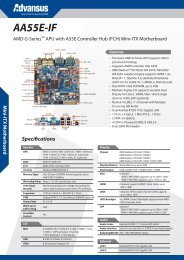

![Download [PDF 0,7MB] - MSC Vertriebs GmbH](https://img.yumpu.com/8276686/1/184x260/download-pdf-07mb-msc-vertriebs-gmbh.jpg?quality=85)
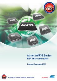
![Download [1.6 MB] - MSC Vertriebs GmbH](https://img.yumpu.com/8227971/1/184x260/download-16-mb-msc-vertriebs-gmbh.jpg?quality=85)