DWDI Nested Inlet Vanes - Twin City Fan & Blower
DWDI Nested Inlet Vanes - Twin City Fan & Blower
DWDI Nested Inlet Vanes - Twin City Fan & Blower

Create successful ePaper yourself
Turn your PDF publications into a flip-book with our unique Google optimized e-Paper software.
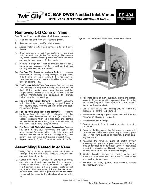
Removing Old Cone or Vane<br />
See Figure 2 for identification of all items referenced.<br />
1. Shut off fan and lock out electrical power.<br />
2. Remove belt guard and/or inlet screens.<br />
3. Adjust motor position and remove belts and drive<br />
sheave.<br />
4. Clean and remove rust from sections of fan shaft<br />
which extend through the fan bearings. File smooth<br />
any burrs. Remove bearing bolts and raise the shaft<br />
enough to take weight off the bearing.<br />
5. Working through fan outlet or through access door,<br />
block under periphery of fan wheel so that fan<br />
housing supports the fan wheel.<br />
6a. For <strong>Fan</strong> With Setscrew Locking Collars — Loosen<br />
setscrews in bearing. Using wedges or pry bars,<br />
slide bearing off end of shaft. If it is necessary to<br />
force bearing, use a brass rod to drive against inner<br />
race of bearing only.<br />
6b. For <strong>Fan</strong>s With Split Type Bearing — Remove bearing<br />
cap, bearing housing and bearing insert off end of<br />
shaft. If the bearing insert must be removed by<br />
inexperienced personnel, it is recommended that the<br />
bearing manufacturer be contacted to provide<br />
instructions for dismounting.<br />
7a. For Old <strong>Inlet</strong> Funnel Removal — Loosen fasteners<br />
which hold inlet cone and bearing support frame to<br />
the housing side. Remove old inlet cone and bearing<br />
support frame.<br />
7b. For Pre-1981 Style <strong>Inlet</strong> Vane Removal — Remove<br />
hardware from old vane which attaches it to the<br />
housing side. Remove control arm (or drive link).<br />
Loosen fasteners which hold inlet cone and bearing<br />
support frame to fan housing side, then remove old<br />
inlet vane and bearing support frame.<br />
7c. For Post-1981 Style <strong>Inlet</strong> Vane Removal — Remove<br />
nut (item 16) and pull connecting arm out of the<br />
way. Loosen fasteners which hold inlet vane and<br />
bearing support frame to the housing side, then<br />
remove the inlet vane and bearing support frame.<br />
8. Repeat steps 4, 6, and 7 on other side of the fan.<br />
Assembling <strong>Nested</strong> <strong>Inlet</strong> Vane<br />
BC, BAF <strong>DWDI</strong> Nestled <strong>Inlet</strong> <strong>Vanes</strong><br />
1. Using Figure 2 as a guide, assemble items 4<br />
through 16 to the inlet vane. Measure threaded linkage<br />
rod (item 6) to fit.<br />
2. Center inlet vane in location of old vane or cone,<br />
and rotate until inlet vane control ring is approximately<br />
in the same position as shown in Figure 3.<br />
If old control linkage is being reused, locate control<br />
ring clip so that connecting link can be reattached.<br />
Be sure that when vane is partially closed the entering<br />
air will be spun in the direction of wheel rotation.<br />
INSTALLATION, OPERATION & MAINTENANCE MANUAL<br />
©2004 <strong>Twin</strong> <strong>City</strong> <strong>Fan</strong> & <strong>Blower</strong><br />
3. For installation of new quadrant, using the dimensions<br />
in Figure 4, position quadrant (item 2 or 2A)<br />
to the housing side. Weld quadrant to the housing<br />
frame (or housing side).<br />
4. Drill a hole in the fan housing side to match the<br />
diameter of control rod (item 3).<br />
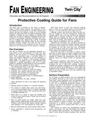
5. Reassemble bearing support frame and bolt it to fan<br />
housing as shown in Figure 1.<br />
6. Reassemble the bearing.<br />
ES-494<br />
May 2004<br />
Figure 1. BC, BAF <strong>DWDI</strong> <strong>Fan</strong> With <strong>Nested</strong> <strong>Inlet</strong> <strong>Vanes</strong><br />
7. Repeat steps 1, 2, 4, 5, and 6 on the other side<br />
of the fan.<br />
8. Remove blocking under the fan wheel and check to<br />
be sure the wheel turns freely. Adjust bearing position<br />
or inlet vane position as required. Tighten bearing<br />
fasteners.<br />
9. Assemble the remaining parts of control system<br />
according to Figure 2. Adjust position of connecting<br />
links as required to enable both vanes to open/close<br />
smoothly and uniformly. Threaded linkage rods (item<br />
6) may have to be cut to required length.<br />
10. Welded threaded linkage rod housing to hex nuts<br />
(item 14). Spot weld the control rod to vane handle<br />
and control linkage bar.<br />
11. Reinstall the drive, guards, inlet screens, access<br />
door hardware, etc.<br />
1 <strong>Twin</strong> <strong>City</strong> Engineering Supplement ES-494
Figure 2. <strong>Nested</strong> <strong>Inlet</strong> Vane Control System for <strong>DWDI</strong> BC, BAF <strong>Fan</strong>s<br />
AIRFLOW<br />
DRIVEN<br />
SIDE<br />
4<br />
2A<br />
9<br />
15<br />
12<br />
8A 10<br />
1<br />
8 10<br />
18<br />
19<br />
17<br />
2<br />
21<br />
11<br />
12<br />
20<br />
BLADE POSITION FOR<br />
CW (CLOCKWISE) FAN<br />
13<br />
14<br />
7<br />
BLADE POSITION FOR CCW<br />
(COUNTERCLOCKWISE) FAN<br />
VIEW FROM DRIVEN SIDE<br />
13<br />
8A<br />
14<br />
BLADE POSITION FOR<br />
CCW (COUNTER-<br />
CLOCKWISE) FAN<br />
NOTES:<br />
1. Items 8, 9, 10, and 11 are used for fan sizes 245 thru 890.<br />
2. Item 8A is used for fan sizes 165 thru 222.<br />
3. Item 2 is used for nonrotatable housing design and is to be welded to the fan housing frame.<br />
4. Item 2A is used for rotatable housing desing and is to be welded on the fan housing.<br />
5. Bearings are to be mounted on the outside of the fan housing.<br />
6. Items 7 and 14 are used for fan sizes 600 and larger.<br />
7. Measure threaded linkage rod length to fit.<br />
22<br />
6<br />
16<br />
5<br />
23<br />
14<br />
6<br />
13<br />
12<br />
7<br />
11<br />
15<br />
13<br />
14<br />
3<br />
8<br />
9<br />
4<br />
12<br />
16<br />
AIRFLOW<br />
19<br />
17<br />
BLADE POSITION FOR<br />
CW (CLOCKWISE) FAN<br />
23<br />
16<br />
VIEW FROM DRIVE SIDE<br />
2 <strong>Twin</strong> <strong>City</strong> Engineering Supplement ES-494<br />
5<br />
DRIVE<br />
SIDE<br />
ITEM DESCRIPTION<br />
01 VANE HANDLE<br />
02 QUADRANT<br />
03 CONTROL ROD<br />
04 CONTROL RING<br />
05 CONTROL LINKAGE BAR<br />
06 THREADED LINKAGE ROD<br />
07 THREADED LINKAGE ROD HSG.<br />
08 CONTROL RING CLIP<br />
09 UNISTRUT<br />
10 UNISTRUT CLAMPING NUT<br />
11 HEX NUT<br />
12 BALL JOINT<br />
13 HEX NUT<br />
14 HEX NUT<br />
15 HEX NUT<br />
16 HEX NUT<br />
17 HEX BOLT<br />
18 NEX NUT<br />
19 FLANGE BEARING<br />
20 SPRING LOCK WASHER<br />
21 FLAT WASHER<br />
22 HEX HEAD SCREW<br />
23 SQUARE HEAD SETSCREW<br />
24 SQUARE HEAD SETSCREW
Figure 3. Control Ring Position<br />
LEAD ROD TOP ON CTR. LEAD ROD TOP ON CTR.<br />
POS. R<br />
POS. L<br />
LEAD ROD TOP ON CTR. LEAD ROD TOP ON CTR.<br />
POS. R<br />
POS. L<br />
LEAD ROD TOP ON CTR. LEAD ROD TOP ON CTR.<br />
LEAD ROD TOP ON CTR. LEAD ROD TOP ON CTR.<br />
3 <strong>Twin</strong> <strong>City</strong> Engineering Supplement ES-494 <strong>Twin</strong> <strong>City</strong> Engineering Supplement ES-494 3<br />
POS. R<br />
POS. R<br />
POS. L<br />
FAN SIZES 165 — 222 CW ROTATION FAN SIZES 165 — 222 CCW ROTATION<br />
POS. L<br />
FAN SIZES 245 — 982 CW ROTATION FAN SIZES 245 — 982 CCW ROTATION<br />
Figure 4. <strong>Nested</strong> <strong>Inlet</strong> Vane Handle Location For Non-rotatable <strong>Fan</strong>s<br />
HOUSING VERT.<br />
CENTERLINE<br />
R<br />
L R<br />
NOTES:<br />
1. For POS. R:<br />
CW fan handle down is open.<br />
CCW fan handle down is closed.<br />
For POS L:<br />
CW fan handle down is closed.<br />
CCW fan handle down is open.<br />
2. Handle location on inlet side of<br />
fan.<br />
3. Reference of AS-13460.<br />
A<br />
THD DBD TAU BAU<br />
TAD UBD BHD<br />
A<br />
HORIZ.<br />
CENTER-<br />
LINE<br />
9.75<br />
PIVOT<br />
45° 1.00<br />
45°<br />
R L R<br />
L<br />
R<br />
OPPOSITE DRIVE SIDE SHOWN<br />
L<br />
R<br />
NOTES:<br />
1. For POS. R:<br />
CW fan handle down is open.<br />
CCW fan handle down is closed.<br />
For POS L:<br />
CW fan handle down is closed.<br />
CCW fan handle down is open.<br />
2. All dimensions are references to AS-13459.<br />
NESTED INLET VANE DIMENSION “A”<br />
FAN HANDLE LOCATION SWSI <strong>DWDI</strong><br />
SIZE<br />
DBD TAD THD TAU UBD BAU BHD CL I CL II<br />
CL III<br />
BCS 17<br />
CL IV<br />
BCS 22,26<br />
CL I CL II CL III<br />
165 L L R R R R L 12.88 12.88 12.88 12.88 12.88 12.88 12.88<br />
182 L L R R R R L 13.75 13.75 14.25 14.75 13.75 13.75 14.25<br />
200 L L R R R R L 14.75 14.75 15.25 15.75 14.75 14.75 15.25<br />
222 L L R R R R L 16.38 16.38 16.88 16.88 16.38 16.38 16.88<br />
245 L R R R R L L 17.50 17.50 18.00 18.00 17.50 17.50 18.00<br />
270 L R R R R L L 18.75 18.75 19.25 19.75 18.75 18.75 19.50<br />
300 L R R R R L L 21.25 21.25 21.75 21.75 21.25 21.25 22.00<br />
330 R R R R R L L 22.75 22.75 23.25 23.50 22.75 23.00 23.50<br />
365 R R R R R L L 24.75 24.75 25.50 25.50 24.75 25.00 25.50<br />
402 R R R R L L L 27.00 27.00 27.25 27.25 27.00 27.25 27.50<br />
445 R R R R L L L 29.00 29.00 29.25 29.75 29.25 29.25 29.50<br />
490 R R R R L L L 31.50 31.75 31.75 32.50 31.75 31.75 32.00<br />
542 R R R R L L L 34.25 34.50 34.50 35.25 34.50 34.75 34.75<br />
600 R R R R L L L 37.50 37.50 38.25 38.25 37.50 37.75 38.50<br />
660 R R R R L L L 41.00 41.00 41.25 41.75 41.25 41.25 41.50<br />
730 R R R R L L L 45.00 45.25 45.50 46.00 45.25 45.50 45.75<br />
807 R R R R L L L 48.75 49.00 49.75 50.00 49.00 49.25 50.00<br />
890 R R R R L L L 54.50 54.50 55.25 55.50 54.75 55.00 55.50<br />
982 R R R R L L L 62.25 62.50 58.50 58.75 62.50 62.75 58.75<br />
L
Figure 5. <strong>Nested</strong> <strong>Inlet</strong> Vane Handle Location For Rotatable <strong>Fan</strong>s<br />
HOUSING VERT.<br />
CENTERLINE<br />
A<br />
THD<br />
1.00<br />
TYP.<br />
A<br />
HORIZ.<br />
CENTER-<br />
LINE<br />
R R R R L<br />
R R<br />
9.75<br />
PIVOT<br />
TAU UBD BAU<br />
BHD<br />
45° 1.00<br />
45°<br />
B<br />
DBD<br />
TAD<br />
CW ROTATION INLET SIDE SHOWN<br />
IF <strong>DWDI</strong>, OPPOSITE DRIVE SIDE.<br />
FAN SIZE 165 182 200 222 245 270 300 330 365<br />
A 11.25 12.25 13.50 14.62 15.88 17.50 19.06 20.44 22.88<br />
B 1.69 1.69 1.69 21.9 2.19 2.19 2.69 2.69 2.69<br />
<strong>Twin</strong> ciTy fan & blower | www.Tcf.com<br />
NOTES:<br />
1. For POS. R:<br />
CW fan handle down is open.<br />
CCW fan handle down is closed.<br />
For POS L:<br />
CW fan handle down is closed.<br />
CCW fan handle down is open.<br />
2. For split housing, consult factory.<br />
5959 Trenton Lane N | Minneapolis, MN 55442 | Phone: 763-551-7600 | Fax: 763-551-7601