Turbo Pressure Blowers - Catalog 1250 - Twin City Fan & Blower
Turbo Pressure Blowers - Catalog 1250 - Twin City Fan & Blower
Turbo Pressure Blowers - Catalog 1250 - Twin City Fan & Blower

You also want an ePaper? Increase the reach of your titles
YUMPU automatically turns print PDFs into web optimized ePapers that Google loves.
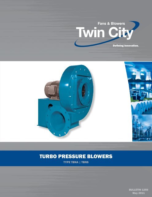
turbo pressure blowers<br />
tYpe tbNA | tbNs<br />
Defining Innovation.<br />
BULLETIN <strong>1250</strong><br />
May 2011
2<br />
TBN <strong>Turbo</strong> <strong>Pressure</strong> <strong><strong>Blower</strong>s</strong><br />
Introduction<br />
The TBN series of fans are low volume, high-pressure<br />
blowers designed for stable operation throughout their<br />
operating range. Multiple outlet sizes and wheel diameters<br />
allow the most efficient selections across a wide<br />
range of operating points. These units incorporate a<br />
high efficiency wheel design at an economical price.<br />
Typical Applications<br />
● Pneumatic conveying ● Chemical processes<br />
● Exhausting ● Thermal oxidation<br />
● Combustion air ● Aeration<br />
● Air knives ● Seal air<br />
Capabilities<br />
● Static pressures to 57" w.g.<br />
● Airflow capabilities to 5400 CFM<br />
● High temperature applications to 600°F<br />
● For higher performance requirements, see below.<br />
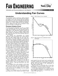
TBNA<br />
Aluminum<br />
Wheel<br />
TBNS<br />
Steel<br />
Wheel<br />
Wheel Construction<br />
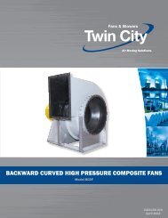
TBNA<br />
The TBNA offers a radial air handling wheel of riveted<br />
aluminum construction. A standard split taperlock<br />
bushing allows for easy wheel removal from<br />
shaft. This wheel is available in both narrow “N” and<br />
wide “W” widths for optimum performance and high<br />
efficiency. The TBNA is designed to handle clean<br />
air applications with temperatures up to 200°F. The<br />
TBNA wheel is a non-reversible design.<br />
TBNS<br />
The TBNS is an all welded radial design steel wheel<br />
that is available in a variety of special materials. The<br />
TBNS wheel is furnished with a split taper-lock bushing<br />
for easy removal and maintenance. This wheel is<br />
available in both narrow “N” and wide “W” widths to<br />
meet specific performance requirements. The TBNS<br />
is designed to handle fumes, light particulates, and<br />
temperatures up to 600°F. The TBNS design is less<br />
efficient than the TBNA and requires a BHP correction.<br />
See the table in the Engineering Data section<br />
for correction factors. The TBNS wheel is a reversible<br />
design.<br />
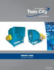
Housing Construction<br />
<strong>Twin</strong> <strong>City</strong> <strong>Fan</strong> & <strong>Blower</strong> also offers the Type<br />
TBA/TBR, Type MBO/MBR/MBW, and Type BCN<br />
<strong>Pressure</strong> <strong><strong>Blower</strong>s</strong>. These blowers offer multiple<br />
outlet sizes and a variety of wheel designs and<br />
diameters to allow the most efficient selections<br />
across a wide range of operating points.<br />
Capabilities: Static pressures to 125" w.g., volumes<br />
to 75,000 CFM, high temperature applications<br />
to 800°F.<br />
All TBN fans come standard with heavy gauge, continuously<br />
welded steel housings and pedestals for<br />
rugged, heavy duty, long term service. All housings<br />
are reversible and rotatable. TBN fans come standard<br />
with an inlet venturi with screen and a round punched<br />
flanged outlet connection.<br />
Type TBR<br />
Refer to Bulletins 1200 (TBA/TBR), 1400 (MBO/<br />
MBR/MBW), and 1450 (BCN) for more specific<br />
information.<br />
Type MBO<br />
©2004 <strong>Twin</strong> <strong>City</strong> <strong>Fan</strong> & <strong>Blower</strong>. All rights reserved throughout the world.<br />
Bulletin illustrations cover the general appearance of <strong>Twin</strong> <strong>City</strong> <strong>Fan</strong> & <strong>Blower</strong> products at the time of<br />
publication and we reserve the right to make changes in design and construction at any time without notice.<br />
<strong>Twin</strong> <strong>City</strong> Bulletin <strong>1250</strong>
3<br />
Arrangements<br />
Arrangement 1 (Belt Driven)<br />
The fan wheel on an Arrangement 1 is overhung on<br />
the shaft, i.e., mounted at the end of the shaft. The<br />
motor can be mounted in any of the four AMCA<br />
standard motor positions, W, X, Y or Z. The two fan<br />
bearings are mounted on the bearing pedestal, out<br />
of the airstream.<br />
Maximum Temperatures:<br />
200°F Aluminum Wheel – TBNA<br />
300°F Steel Wheel – TBNS<br />
600°F High Temperature Construction – TBNS<br />
Arrangement 4 (Direct Drive)<br />
The fan wheel on an Arrangement 4 is mounted<br />
directly on the motor shaft with the motor mounted<br />
on a pedestal. An Arrangement 4 offers a compact,<br />
low maintenance design, as there are no fan bearings,<br />
fan shaft or drive parts to maintain.<br />
Maximum Temperature: 180°F.<br />
Arrangement 8 (Direct Drive)<br />
An Arrangement 8 is a modified version of an<br />
Arrangement 1 used for direct drive. The bearing<br />
pedestal is extended to accommodate the motor. A<br />
flexible coupling connects the fan and motor shaft.<br />
Maximum Temperatures:<br />
200°F Aluminum Wheel – TBNA<br />
300°F Steel Wheel – TBNS<br />
600°F High Temperature Construction – TBNS<br />
Arrangement 4<br />
with Inlet Venturi &<br />
Screen<br />
Arrangement 4<br />
with Punched<br />
Outlet Flange<br />
Arrangement 8<br />
with Punched<br />
Inlet Flange<br />
Arrangement 1 with<br />
Optional Shaft &<br />
Bearing Guard<br />
<strong>Twin</strong> <strong>City</strong> Bulletin <strong>1250</strong>
4<br />
Inlet and Outlet Connections/Accessories<br />
Inlet Connections<br />
The following inlet connections are available at no<br />
additional charge:<br />
Inlet Venturi with Screen<br />
Recommended for all non-ducted inlet installations to<br />
obtain catalog performance. Unless otherwise specified,<br />
an inlet venturi with screen will be furnished.<br />
Flanged Inlet<br />
For bolted pipe or duct connections. Flanged inlet is<br />
punched to ANSI 125/150 hole pattern.<br />
Inlet Pipe Assembly<br />
For slip-on pipe or duct connections.<br />
Inlet Accessories<br />
The following optional inlet side accessories are available:<br />
Inlet Filter<br />
Cleanable wire mesh filter<br />
with mounting assembly. Filter<br />
suitable for atmospheric air<br />
only and cannot be used in<br />
a ducted inlet application.<br />
<strong>Fan</strong> must be specified with<br />
flanged inlet.<br />
Inlet Filter With Hood<br />
Inlet filter described above with a hood to protect<br />
against the elements.<br />
Inlet Silencer<br />
Welded steel construction with acoustical absorption<br />
material to reduce noise emanating from fan inlet.<br />
Flanged connection is suggested for mounting to the<br />
inlet of the fan. The opposite end of the silencer<br />
can be furnished with an inlet venturi, inlet flange, or<br />
inlet pipe assembly. Unless otherwise specified, the<br />
silencer will be furnished with flanges (punched) at<br />
both ends.<br />
Outlet Connections<br />
Flanged Outlet<br />
Outlet flange punched to ANSI 125/150 hole pattern<br />
for bolted connection is standard.<br />
Plain Pipe Outlet<br />
An optional plain pipe outlet is available for slip type<br />
connections. Refer to the dimensional drawings.<br />
Outlet Accessories<br />
The following optional outlet side accessories are<br />
available:<br />
Flexible Connector for Flanged Outlet<br />
Companion flange with rubber sleeve<br />
and clamps offers flexible connection<br />
between the fan and outlet ductwork.<br />
Flexible rubber sleeve is good to 200°F<br />
operation.<br />
Flexible Connector for Plain Pipe Outlet<br />
Rubber sleeve with clamps for fans<br />
ordered with optional plain pipe<br />
outlet.<br />
Outlet Blast Gate<br />
A wafer-type butterfly valve for<br />
mounting to outlet flange allows<br />
controlling flow to full shutoff.<br />
Available for automatic control.<br />
Maximum temperature 250°F.<br />
Built-in Outlet Damper<br />
A low cost single blade damper installed near the<br />
discharge of the fan housing for volume control<br />
where moderate leakage can be allowed. Available<br />
for manual control only.<br />
Outlet Silencer<br />
Reduces noise emanating from fan outlet. Construction<br />
similar to inlet silencer.<br />
<strong>Twin</strong> <strong>City</strong> Bulletin <strong>1250</strong>
5<br />
Accessories<br />
Shaft Closure Plate<br />
Aluminum plate to reduce air leakage from the fan<br />
housing.<br />
Shaft Seal<br />
Standard shaft seal is a<br />
ceramic felt material sandwiched<br />
between the housing<br />
and an aluminum retaining<br />
plate. Seal is good to 600°F.<br />
Shaft seal does not make fan<br />
gas tight. Contact factory for<br />
tighter sealing options.<br />
Drain<br />
Standard 3 ∕4" NPT half coupling located at the lowest<br />
point of the housing. Available with or without plug.<br />
Inspection Port<br />
Heavy duty bolted panel provides access for wheel<br />
inspection.<br />
Shaft & Bearing Guards<br />
OSHA style to enclose the shaft and bearings.<br />
Painted safety yellow.<br />
Belt Guards<br />
OSHA style to enclose the V-belt drive. Painted safety<br />
yellow.<br />
Optional Construction<br />
High Temperature Construction<br />
Available for Model TBNS only.<br />
301 to 500°F Package includes shaft seal, shaft<br />
cooler with guard, high temperature<br />
grease, and TCF blue enamel paint.<br />
501 to 600°F Package includes shaft seal, shaft<br />
cooler with guard, high temperature<br />
grease, and high temperature aluminum<br />
paint.<br />
Special Materials Stainless steel and other special<br />
alloys are available in the type<br />
TBNS radial design.<br />
Spark Resistant Construction<br />
Available for Model TBNA only. <strong>Fan</strong> applications may<br />
involve the handling of fumes or vapors. Such applications<br />
require careful consideration by the system<br />
Coupling Guards<br />
OSHA style to enclose the coupling. Painted safety<br />
yellow.<br />
Unitary Base (Arrangement 1<br />
only)<br />
Steel structural base for mounting fan and motor on<br />
common structure. Allows for complete assembly of<br />
fan, motor, and v-belt drive. Must be bolted to a rigid<br />
support structure.<br />
Isolation Base (Arrangements 1<br />
and 4)<br />
Unitary base with 1" deflection isolators. Not recommended<br />
for Arr. 8.<br />
Inertia Base (All Arrangements)<br />
Steel structural base complete with 1" deflection isolators<br />
and rebar. Concrete by others.<br />
Vibration Rails<br />
Available for Arrangement 4 with RIS isolators.<br />
Motors<br />
<strong>Twin</strong> <strong>City</strong> <strong>Fan</strong> & <strong>Blower</strong> provides and recommends<br />
3600 RPM motors with cast housings and cast feet<br />
or with a full length fabricated steel base for troublefree<br />
operation.<br />
designer to insure the safe handling of such gases.<br />
<strong>Twin</strong> <strong>City</strong> <strong>Fan</strong> & <strong>Blower</strong> offers the following classifications<br />
of spark resistant construction per AMCA<br />
Standard 99-0401-86. It is the specifier’s or the<br />
user’s responsibility to specify the type of spark resistant<br />
construction with full recognition of the potential<br />
hazards and the degree of protection required.<br />
Construction<br />
Type A All parts of the fan in contact with the airstream<br />
must be made of nonferrous material<br />
— usually aluminum and limited to 200°F.<br />
Type B The fan shall have a nonferrous wheel<br />
and nonferrous rub ring about the opening<br />
through which the shaft passes — usually<br />
aluminum wheel and rub ring and limited to<br />
200°F.<br />
Type C Not available.<br />
<strong>Twin</strong> <strong>City</strong> Bulletin <strong>1250</strong>
6<br />
Engineering Data<br />
Steel Wheel (TBNS)<br />
Horsepower Correction Factors<br />
(Increase BHP from curves when using steel wheel)<br />
SIZE BHP CORRECTION FACTOR<br />
14N to 18N 1.03<br />
14W to 18W 1.09<br />
19N to 22N 1.14<br />
19W to 22W 1.12<br />
23N to 26N 1.10<br />
23W to 26W 1.10<br />
<strong>Pressure</strong> Conversions<br />
MULTIPLY BY TO OBTAIN<br />
PSI 27.7123 IN. W.G.<br />
PSI 16 OSI<br />
OSI 1.732 IN. W.G.<br />
OSI 0.0625 PSI<br />
IN. W.G. 0.57737 OSI<br />
IN. W.G.<br />
PSI = Pounds per square inch<br />
OSI = Ounces per square inch<br />
In. W.G. = Inches water gauge<br />
0.03609 PSI<br />
Material Specifications<br />
SIZE<br />
SIDES<br />
HOUSING<br />
SCROLL FRAME<br />
MOTOR<br />
BASE<br />
SHAFT BEARING<br />
DIA. CODE MAX. RPM<br />
ARR. 1 & 8 ARR. 1 & 8 TBNA TBNS À<br />
14 to 18 10 GA. 10 GA. 0.25" x 2" 0.25" 13∕16 XHDB 4000 4000<br />
19 to 22 10 GA. 10 GA. 0.25" x 2" 0.25" 17∕16 RB 3900 3900<br />
23 to 26 10 GA. 10 GA. 0.25" x 2" 0.25" 17∕16 RB 3800 3600<br />
Derating of speed is not required for stainless steel or high temperature construction.<br />
Bare <strong>Fan</strong> Weights (Lbs.)<br />
Wheel Weights and<br />
WR 2 (moment of inertia in lb-ft 2 )<br />
WHEEL<br />
SIZE TBNA (ALUMINUM) TBNS (STEEL)<br />
WT. (LB) WR 2 (LB-FT 2 ) WT. (LB) WR 2 (LB-FT 2 )<br />
14N 10.5 3.3 13.1 1.9<br />
14W 10.5 4.0 12.8 2.0<br />
15N 10.6 3.4 14.6 2.5<br />
15W 10.6 4.1 14.6 2.7<br />
16N 10.7 3.5 16.2 3.2<br />
16W 10.7 4.2 16.5 3.4<br />
17N 10.8 3.7 18.0 4.0<br />
17W 10.9 4.5 18.5 4.3<br />
18N 11.0 3.9 19.8 5.0<br />
18W 11.1 4.7 20.5 5.4<br />
19N 14.7 8.1 21.7 6.1<br />
19W 14.9 9.7 22.0 6.4<br />
20N 14.8 8.4 23.7 7.4<br />
20W 15.2 10.1 24.1 7.8<br />
21N 15.0 8.8 25.8 8.9<br />
21W 15.5 10.6 26.4 9.5<br />
22N 15.2 9.3 28.0 10.7<br />
22W 15.8 11.2 28.8 11.3<br />
23N 19.8 16.8 43.2 19.3<br />
23W 21.1 21.6 43.9 20.3<br />
24N 20.1 17.5 46.8 22.7<br />
24W 21.5 22.5 47.8 24.1<br />
25N 20.3 18.2 50.6 26.6<br />
25W 21.9 23.4 51.9 28.2<br />
26N 20.5 19.0 54.5 31.0<br />
26W 22.3 24.4 56.1 32.9<br />
ARRANGEMENT 1 ARRANGEMENT 4 ARRANGEMENT 8<br />
SIZE TBNA TBNS TBNA TBNS TBNA TBNS<br />
14N to 18N 202 212 185 195 282 292<br />
14W to 18W 218 230 201 213 298 310<br />
19N to 22N 278 292 252 266 395 409<br />
19W to 22W 335 351 309 325 452 468<br />
23N to 26N 392 432 366 406 524 564<br />
23W to 26W 445 473 419 447 577 605<br />
Inlet Suction <strong>Pressure</strong> Correction<br />
If the inlet pressure is suction or negative, the static<br />
pressure required must be corrected by the inlet<br />
density ratio.<br />
Example: Operating conditions: 70°F at sea level.<br />
System resistance at the inlet of the fan is 40".<br />
The correction factor from the table at right is 0.902,<br />
or it can be calculated as follows:<br />
(407.5 – 40") ÷ 407.5 = 0.902<br />
Equivalent static pressure to be used for selection<br />
from the standard performance curves:<br />
40" ÷ 0.902 = 44.36"<br />
Actual air density at the inlet of the fan:<br />
0.075 lb/ft3 x 0.902 = 0.0676 lb/ft3 Inlet Suction <strong>Pressure</strong> Correction Factors<br />
INLET<br />
SUCTION CORRECTION<br />
PRESSURE FACTOR<br />
(IN. W.G.)<br />
5 0.988<br />
10 0.975<br />
15 0.963<br />
20 0.951<br />
25 0.939<br />
30 0.926<br />
Due to speed and load ratings,<br />
bearing substitution is not permitted.<br />
XHDB = Extra heavy duty ball bearings<br />
such as Link Belt<br />
P-U319<br />
RB = Roller bearings such as<br />
Link Belt PB22423<br />
INLET<br />
SUCTION CORRECTION<br />
PRESSURE FACTOR<br />
(IN. W.G.)<br />
35 0.914<br />
40 0.902<br />
45 0.890<br />
50 0.877<br />
55 0.865<br />
60 0.853<br />
Correction Factor = (407.5 – Inlet Suction <strong>Pressure</strong>) ÷ 407.5<br />
<strong>Twin</strong> <strong>City</strong> Bulletin <strong>1250</strong>
7<br />
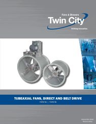
Performance Data<br />
Selection<br />
The performance curves shown are for type TBNA<br />
and are based on standard air density: 70°F at sea<br />
level (0.075 lb/ft 3 ). A brake horsepower correction factor<br />
must be applied for type TBNS (see page 6).<br />
Selection Steps<br />
1. Locate the CFM required on the horizontal axis.<br />
2. Follow a vertical line up to the fan curve closest to<br />
the required SP. This will determine the fan size.<br />
The dotted lines represent system characteristic<br />
curves.<br />
3. Interpolate BHP.<br />
Selection Example:<br />
Size = 22N4 RPM = 3500<br />
Density = 0.075 lb/ft 3 Outlet Velocity = 5727 FPM<br />
CFM = 500 BHP (TBNA) = 4.85<br />
SP = 33.8" BHP (TBNS) = 4.85 x 1.14 = 5.53<br />
19N4, 20N4, 21N4, 22N4 3500 RPM<br />
STATIC PRESSURE (IN. W.G.)<br />
CFM<br />
(OV)<br />
STATIC PRESSURE (IN. W.G.)<br />
40<br />
35<br />
30<br />
25<br />
20<br />
CFM<br />
(OV)<br />
0 50 100 150 200 250 300 350 400 450 500 550 600 650 700<br />
(0) (572) (1145) (1718) (2290) (2863) (3436) (4009) (4581) (5154) (5727) (6300) (6872) (7445) (8018)<br />
30<br />
25<br />
20<br />
15<br />
10<br />
2.5<br />
1<br />
2<br />
1.5<br />
1.25<br />
1<br />
1<br />
2.5<br />
1.5<br />
1.25<br />
2<br />
1.75<br />
3<br />
1.25<br />
1.25<br />
2.5<br />
3<br />
3.5<br />
2.5<br />
SYSTEM<br />
CURVE<br />
2<br />
1.75<br />
1.5<br />
2.25<br />
1.5<br />
1.5<br />
2<br />
1.75<br />
BHP<br />
3<br />
2.5<br />
1.75<br />
3.5<br />
1.75<br />
0 50 100 150 200 250 300 350 400 450 500 550 600 650 700<br />
(0) (572) (1145) (1718) (2290) (2863) (3436) (4009) (4581) (5154) (5727) (6300) (6872) (7445) (8018)<br />
4<br />
BHP<br />
2<br />
2<br />
Model Nomenclature<br />
3<br />
2.75<br />
2.25<br />
2<br />
3.5<br />
2.25<br />
SYSTEM<br />
CURVE<br />
2<br />
3<br />
4.5<br />
4<br />
2.5<br />
3.5<br />
3.25<br />
2.25<br />
TBNA 20 N 4<br />
MODEL OUTLET SIZE (IN.)<br />
TBNA – Aluminum wheel 4 6 8<br />
TBNS – Steel wheel (apply 10 12<br />
BHP correction factors<br />
from page 6)<br />
WHEEL DIAMETER (IN.) WHEEL WIDTH<br />
14 17 20 23 26 N – Narrow<br />
15 18 21 24 W – Wide<br />
16 19 22 25<br />
4 In. Outlet Outlet Area: 0.09 ft 2<br />
14N4, 15N4, 16N4, 17N4, 18N4 3500 RPM<br />
Performance shown is with a ducted outlet, and a ducted inlet or inlet with venturi.<br />
2.5<br />
4.5<br />
4<br />
5<br />
2.75<br />
4<br />
3.5 3.75<br />
2.5<br />
2.25<br />
3<br />
2.75<br />
5<br />
4.5<br />
3<br />
2.5<br />
3.25<br />
2.75<br />
22N4<br />
21N4<br />
20N4<br />
19N4<br />
40<br />
35<br />
30<br />
25<br />
20<br />
30<br />
<strong>Twin</strong> <strong>City</strong> Bulletin <strong>1250</strong><br />
4<br />
18N4<br />
17N4<br />
16N4<br />
15N4<br />
14N4<br />
25<br />
20<br />
15<br />
10<br />
STATIC PRESSURE (IN. W.G.)<br />
CFM<br />
(OV)<br />
STATIC PRESSURE (IN. W.G.)<br />
CFM<br />
(OV)
8<br />
STATIC PRESSURE (IN. W.G.)<br />
CFM<br />
(OV)<br />
STATIC PRESSURE (IN. W.G.)<br />
6 In. Outlet Outlet Area: 0.20 ft 2<br />
23N6, 24N6, 25N6, 26N6 3500 RPM<br />
STATIC PRESSURE (IN. W.G.)<br />
60<br />
55<br />
50<br />
45<br />
40<br />
30<br />
25<br />
20<br />
15<br />
1.5<br />
2<br />
7<br />
2.5<br />
2<br />
2<br />
6<br />
7.5<br />
7<br />
2.5<br />
7.5<br />
3<br />
6<br />
2.5<br />
2.5<br />
7<br />
8<br />
2<br />
8<br />
BHP<br />
3<br />
3.5<br />
BHP<br />
7.5<br />
7<br />
3<br />
9<br />
9<br />
8<br />
4<br />
3.5<br />
3<br />
SYSTEM<br />
CURVE<br />
7.5<br />
14W6, 15W6, 16W6, 17W6, 18W6 3500 RPM<br />
10<br />
0 100 200 300 400 500 600 700 800 900 1000 1100 1200 1300 1400<br />
(0) (510) (1020) (1530) (2040) (2551) (3061) (3571) (4081) (4591) (5102) (5612) (6122) (6632) (7142)<br />
3.5<br />
2.5<br />
10<br />
10<br />
CFM 0 100 200 300 400 500 600 700 800 900 1000 1100 1200 1300 1400 CFM<br />
(OV) (0) (510) (1020) (1530) (2040) (2551) (3061) (3571) (4081) (4591) (5102) (5612) (6122) (6632) (7142) (OV)<br />
8<br />
10<br />
4<br />
9<br />
SYSTEM<br />
CURVE<br />
19N6, 20N6, 21N6, 22N6 3500 RPM<br />
CFM<br />
(OV)<br />
40<br />
35<br />
30<br />
25<br />
20<br />
2.5<br />
3<br />
3.5<br />
2.5<br />
3<br />
3.5<br />
4<br />
BHP<br />
3<br />
3.5<br />
4.5<br />
4<br />
3.5<br />
5<br />
4<br />
4.5<br />
5.5<br />
SYSTEM<br />
CURVE<br />
0 100 200 300 400 500 600 700 800 900 1000 1100 1200 1300 1400<br />
(0) (510) (1020) (1530) (2040) (2551) (3061) (3571) (4081) (4591) (5102) (5612) (6122) (6632) (7142)<br />
Performance shown is with a ducted outlet, and a ducted inlet or inlet with venturi.<br />
4<br />
5<br />
4.5<br />
6<br />
4.5<br />
5.5<br />
5<br />
6.5<br />
6<br />
5<br />
4.5<br />
5.5<br />
7<br />
11<br />
6.5<br />
4.5<br />
4<br />
9<br />
6<br />
5.5<br />
5<br />
11<br />
7.5<br />
3.5<br />
10<br />
7<br />
3<br />
12<br />
8<br />
6.5<br />
6<br />
5<br />
12<br />
5.5<br />
4.5<br />
10<br />
11<br />
7.5<br />
4<br />
8.5<br />
6.5<br />
13<br />
6.5<br />
6<br />
5.5<br />
8<br />
3.5<br />
9<br />
13<br />
7<br />
12<br />
11<br />
4.5<br />
14<br />
8.5<br />
7<br />
4.5<br />
6.5<br />
7.5<br />
5.5<br />
14<br />
5<br />
9<br />
13<br />
12<br />
7.5<br />
7<br />
4<br />
15<br />
30<br />
<strong>Twin</strong> <strong>City</strong> Bulletin <strong>1250</strong><br />
8<br />
19N6<br />
6<br />
26N6<br />
25N6<br />
24N6<br />
23N6<br />
22N6<br />
21N6<br />
20N6<br />
18W6<br />
17W6<br />
16W6<br />
15W6<br />
14W6<br />
40<br />
60<br />
55<br />
50<br />
45<br />
40<br />
35<br />
30<br />
25<br />
20<br />
25<br />
20<br />
15<br />
STATIC PRESSURE (IN. W.G.)<br />
CFM<br />
(OV)<br />
STATIC PRESSURE (IN. W.G.)<br />
CFM<br />
(OV)<br />
STATIC PRESSURE (IN. W.G.)
9<br />
8 In. Outlet Outlet Area: 0.35 ft 2<br />
23N8, 24N8, 25N8, 26N8 3500 RPM<br />
STATIC PRESSURE (IN. W.G.)<br />
CFM<br />
(OV)<br />
55<br />
50<br />
45<br />
40<br />
35<br />
8<br />
10<br />
8<br />
BHP<br />
10<br />
8<br />
12<br />
10<br />
12<br />
10<br />
14<br />
SYSTEM<br />
CURVE<br />
12<br />
15<br />
14<br />
12<br />
16<br />
15<br />
14<br />
0 200 400 600 800 1000 1200 1400 1600 1800 2000 2200 2400 2600 2800<br />
(0) (573) (1146) (1719) (2292) (2865) (3438) (4011) (4585) (5157) (5730) (6303) (6876) (7449) (8022)<br />
19W8, 20W8, 21W8, 22W8 3500 RPM<br />
STATIC PRESSURE (IN. W.G.)<br />
CFM<br />
(OV)<br />
40<br />
35<br />
30<br />
25<br />
20<br />
5<br />
6<br />
5<br />
5<br />
5<br />
6<br />
7<br />
6<br />
7.5 8<br />
7<br />
6<br />
7.5<br />
7<br />
8<br />
9<br />
7.5<br />
7<br />
8<br />
9<br />
10<br />
7.5<br />
9<br />
8<br />
11<br />
10<br />
0 200 400 600 800 1000 1200 1400 1600 1800 2000 2200 2400 2600 2800<br />
(0) (573) (1146) (1719) (2292) (2865) (3438) (4011) (4585) (5157) (5730) (6303) (6876) (7449) (8022)<br />
16<br />
15<br />
11<br />
10<br />
12<br />
9<br />
18<br />
14<br />
13<br />
12<br />
11<br />
SYSTEM<br />
CURVE<br />
15W8, 16W8, 17W8, 18W8 3500 RPM<br />
STATIC PRESSURE (IN. W.G.)<br />
CFM<br />
(OV)<br />
25<br />
20<br />
15<br />
10<br />
0<br />
3<br />
3<br />
4<br />
3<br />
4<br />
5<br />
4<br />
5<br />
4<br />
6<br />
5<br />
6<br />
7<br />
SYSTEM<br />
CURVE<br />
0 200 400 600 800 1000 1200 1400 1600 1800 2000 2200 2400 2600 2800<br />
(0) (573) (1146) (1719) (2292) (2865) (3438) (4011) (4584) (5157) (5730) (6303) (6876) (7449) (8022)<br />
Performance shown is with a ducted outlet, and a ducted inlet or inlet with venturi.<br />
5<br />
7.5<br />
6<br />
7<br />
8<br />
7.5<br />
7<br />
6<br />
16<br />
8<br />
15<br />
10<br />
20<br />
18<br />
9<br />
13<br />
16<br />
BHP<br />
14<br />
7.5<br />
12<br />
BHP<br />
18<br />
9<br />
11<br />
22<br />
20<br />
15<br />
10<br />
8<br />
14<br />
18<br />
13<br />
7<br />
16<br />
12<br />
20<br />
15<br />
24<br />
22<br />
11<br />
14<br />
10<br />
7.5<br />
17<br />
9<br />
20<br />
16<br />
8<br />
13<br />
26<br />
22<br />
15<br />
24<br />
18<br />
17<br />
10<br />
14<br />
11<br />
24<br />
26<br />
23N8<br />
19<br />
16<br />
15W8<br />
18<br />
19W8<br />
26N8<br />
25N8<br />
24N8<br />
22W8<br />
21W8<br />
20W8<br />
18W8<br />
17W8<br />
16W8<br />
55<br />
50<br />
45<br />
40<br />
35<br />
40<br />
35<br />
30<br />
25<br />
20<br />
25<br />
20<br />
15<br />
10<br />
<strong>Twin</strong> <strong>City</strong> Bulletin <strong>1250</strong><br />
0<br />
STATIC PRESSURE (IN. W.G.)<br />
CFM<br />
(OV)<br />
STATIC PRESSURE (IN. W.G.)<br />
CFM<br />
(OV)<br />
STATIC PRESSURE (IN. W.G.)<br />
CFM<br />
(OV)
10<br />
10 In. Outlet Outlet Area: 0.55 ft 2<br />
23W10, 24W10, 25W10, 26W10 3550 RPM<br />
STATIC PRESSURE (IN. W.G.)<br />
CFM<br />
(OV)<br />
55<br />
50<br />
45<br />
40<br />
15<br />
15<br />
BHP<br />
15<br />
15<br />
20<br />
20<br />
SYSTEM<br />
CURVE<br />
20<br />
25<br />
20<br />
25<br />
0 300 600 900 1200 1500 1800 2100 2400 2700 3000 3300 3600 3900 4200<br />
(0) (550) (1100) (1651) (2201) (2752) (3302) (3853) (4403) (4954) (5504) (6055) (6605) (7155) (7706)<br />
21W10, 22W10 3550 RPM<br />
STATIC PRESSURE (IN. W.G.)<br />
CFM<br />
(OV)<br />
40<br />
35<br />
30<br />
25<br />
8<br />
8<br />
10<br />
BHP<br />
10<br />
12<br />
12<br />
14<br />
SYSTEM<br />
CURVE<br />
15<br />
14<br />
16<br />
15 16<br />
0 300 600 900 1200 1500 1800 2100 2400 2700 3000 3300 3600 3900 4200<br />
(0) (550) (1100) (1651) (2201) (2752) (3302) (3853) (4403) (4954) (5504) (6055) (6605) (7155) (7706)<br />
25<br />
18<br />
30<br />
18<br />
25<br />
30<br />
20<br />
30<br />
35<br />
22<br />
20<br />
35<br />
30<br />
24<br />
22<br />
25<br />
40<br />
35<br />
24<br />
40<br />
23W10<br />
25<br />
21W10<br />
19W10, 20W10 3550 RPM<br />
STATIC PRESSURE (IN. W.G.)<br />
CFM<br />
(OV)<br />
35<br />
30<br />
25<br />
20<br />
15<br />
6<br />
6<br />
8<br />
8<br />
10<br />
10<br />
12<br />
SYSTEM<br />
CURVE<br />
0 300 600 900 1200 1500 1800 2100 2400 2700 3000 3300 3600 3900 4200<br />
(0) (550) (1100) (1651) (2201) (2752) (3302) (3853) (4403) (4954) (5504) (6055) (6605) (7155) (7706)<br />
Performance shown is with a ducted outlet, and a ducted inlet or inlet with venturi.<br />
BHP<br />
12<br />
14<br />
15<br />
14<br />
16<br />
15<br />
16<br />
18<br />
18<br />
20<br />
26<br />
22<br />
19W10<br />
28<br />
40<br />
20W10<br />
26W10<br />
25W10<br />
24W10<br />
22W10<br />
55<br />
50<br />
45<br />
40<br />
40<br />
35<br />
30<br />
25<br />
35<br />
30<br />
25<br />
20<br />
15<br />
<strong>Twin</strong> <strong>City</strong> Bulletin <strong>1250</strong><br />
STATIC PRESSURE (IN. W.G.)<br />
CFM<br />
(OV)<br />
STATIC PRESSURE (IN. W.G.)<br />
CFM<br />
(OV)<br />
STATIC PRESSURE (IN. W.G.)<br />
CFM<br />
(OV)
11<br />
12 In. Outlet Outlet Area: 0.79 ft 2<br />
25W12, 26W12 3550 RPM<br />
STATIC PRESSURE (IN. W.G.)<br />
CFM<br />
(OV)<br />
60<br />
55<br />
50<br />
45<br />
40<br />
15<br />
15<br />
BHP<br />
20<br />
20<br />
25<br />
25<br />
SYSTEM<br />
CURVE<br />
30<br />
30<br />
0 400 800 1200 1600 2000 2400 2800 3200 3600 4000 4400 4800 5200 5600<br />
(0) (509) (1019) (1528) (2038) (2547) (3057) (3566) (4076) (4585) (5095) (5605) (6114) (6624) (7133)<br />
23W12, 24W12 3550 RPM<br />
STATIC PRESSURE (IN. W.G.)<br />
CFM<br />
(OV)<br />
50<br />
45<br />
40<br />
35<br />
15<br />
15<br />
20<br />
20<br />
SYSTEM<br />
CURVE<br />
0 400 800 1200 1600 2000 2400 2800 3200 3600 4000 4400 4800 5200 5600<br />
(0) (509) (1019) (1528) (2038) (2547) (3057) (3566) (4076) (4585) (5095) (5605) (6114) (6624) (7133)<br />
Performance shown is with a ducted outlet, and a ducted inlet or inlet with venturi.<br />
25<br />
BHP<br />
25<br />
30<br />
35<br />
35<br />
30<br />
40<br />
35<br />
40<br />
45<br />
35<br />
40<br />
45<br />
50<br />
40<br />
45<br />
50<br />
25W12<br />
23W12<br />
26W12<br />
24W12<br />
60<br />
55<br />
50<br />
45<br />
40<br />
<strong>Twin</strong> <strong>City</strong> Bulletin <strong>1250</strong><br />
50<br />
45<br />
40<br />
35<br />
STATIC PRESSURE (IN. W.G.)<br />
CFM<br />
(OV)<br />
STATIC PRESSURE (IN. W.G.)<br />
CFM<br />
(OV)
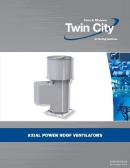
12<br />
DRAWN 12/20/99<br />
TYPE "TBNA" AND "TBNS" ARR. 1 SWSI ROTATABLE<br />
Z<br />
P<br />
HE HA<br />
HA + 1.63<br />
HH<br />
REVISED 10/01/03<br />
TWIN CITY FAN & BLOWER<br />
MINNEAPOLIS, MINNESOTA 55442<br />
HD<br />
DWG. No. BC16177D<br />
J-0.38<br />
J<br />
HC<br />
AA<br />
O.D.<br />
2.00<br />
C LDISCH.<br />
JOB:<br />
LOC.:<br />
S.O. NO.:<br />
CERT. BY:<br />
SIZE DISCH ROT<br />
UNIT #<br />
HB<br />
KL<br />
0.31<br />
DISCH.<br />
CL<br />
Q<br />
KS<br />
Q<br />
C<br />
O.D.<br />
FAN HSG.<br />
CL F<br />
O.D.<br />
PF<br />
I.D.<br />
FAN HSG.<br />
CL FAN HSG.<br />
CL D<br />
SD<br />
SE<br />
PLAIN PIPE OUTLET<br />
(OPTIONAL)<br />
TS<br />
OV<br />
BHP<br />
RPM<br />
SP<br />
CFM<br />
D<br />
CL FAN SHAFT<br />
HF<br />
CW TAU<br />
HC<br />
HB<br />
0.31<br />
HG<br />
ACCESSORIES REQ'D .<br />
INLET<br />
PIPE<br />
ASS'Y<br />
(OPTIONAL)<br />
FLANGED<br />
INLET<br />
(OPTIONAL)<br />
VENTURI<br />
INLET (STD)<br />
HD<br />
HA<br />
B OUTS. HSG.<br />
H<br />
(4) 0.56 DIA.<br />
BASE HOLES<br />
GC<br />
D<br />
D<br />
G<br />
A<br />
I.D.<br />
PF<br />
I.D.<br />
CW UBD CW TAD<br />
M<br />
HF<br />
CC<br />
O.D.<br />
F<br />
O.D.<br />
FAN HSG.<br />
CL CLOCKWISE ROTATION<br />
TOP HORIZONTAL DISCHARGE<br />
'CW THD'<br />
WITH STD. FLANGED OUTLET<br />
HB<br />
HE<br />
HA<br />
CL MOTOR SHAFT<br />
HH<br />
HG<br />
M<br />
"FN" NO. OF "DJ"<br />
HOLES EQUALLY<br />
SPACED ON "FB"<br />
BOLT CIRCLE<br />
"NH" NO. OF "DH"<br />
HOLES EQUALLY<br />
SPACED ON "BC"<br />
BOLT CIRCLE<br />
D<br />
HC<br />
D<br />
OUTLET FLANGE<br />
INLET FLANGE<br />
L K<br />
FOUNDATION PLAN<br />
NOTES:<br />
1. 'CW' ROTATION SHOWN, 'CCW' ROTATION<br />
SIMILAR BUT OPPOSITE<br />
2. BOLT PATTERNS ON INLET AND OUTLET<br />
FLANGES STRADDLE CENTERLINE<br />
3. INLET SCREEN INCLUDED WITH VENTURI INLET<br />
CW BHD CW BAU<br />
SIZE A AA B BC C CC D DH DJ F FBFN G GC H HA HB HC HD HE HF HG HH J K KL KS L M NH P PF Q SD SE Z<br />
14N4, 15N4 4.00 4.50 3.88 9.50 6.63 9.00 17.75 0.88 0.75 11.00 7.50 8 19.50 9.75 11.63 18.25 24.44 16.31 14.00 13.63 13.19 12.75 12.31 5.56 3.38 2.38 .25x.13 8.63 8.88 8 16.19 6.00 11.75 1.19 2.63 4.56<br />
16N4, 17N4, 18N4<br />
14W6, 15W6 6.00 6.63 6.25 11.75 8.63 11.00 17.75 0.88 0.88 13.50 9.50 8 19.50 9.75 11.63 18.25 25.13 17.31 14.00 13.63 13.19 12.75 12.31 6.69 4.50 2.38 .25x.13 8.63 8.88 8 17.38 8.00 11.75 1.19 2.63 6.38<br />
16W6, 17W6, 18W6<br />
15W8, 16W8 8.00 8.63 6.25 11.75 8.63 13.50 17.75 0.88 0.88 13.50 11.75 8 19.50 9.75 11.63 18.25 26.00 18.56 14.00 13.63 13.19 12.75 12.31 6.69 4.50 2.38 .25x.13 8.63 8.88 8 17.38 8.00 11.75 1.19 2.63 6.38<br />
17W8, 18W8<br />
19N4, 20N4 4.00 4.50 3.88 9.50 6.63 9.00 23.00 0.88 0.75 11.00 7.50 8 23.50 11.75 17.13 17.75 26.25 19.38 17.00 16.50 16.00 15.50 15.00 6.06 3.38 3.25 .38x.19 14.13 10.88 8 23.06 6.00 14.88 1.44 4.00 4.56<br />
21N4, 22N4<br />
19N6, 20N6 6.00 6.63 3.88 9.50 6.63 11.00 23.00 0.88 0.88 11.00 9.50 8 23.50 11.75 17.13 17.75 26.94 20.38 17.00 16.50 16.00 15.50 15.00 6.06 3.38 3.25 .38x.19 14.13 10.88 8 23.06 6.00 14.88 1.44 4.00 4.56<br />
21N6, 22N6<br />
19W8, 20W8 8.00 8.63 6.25 11.75 8.63 13.50 23.00 0.88 0.88 13.50 11.75 8 23.50 11.75 17.13 17.75 27.88 21.63 17.00 16.50 16.00 15.50 15.00 6.69 4.50 3.25 .38x.19 14.13 10.88 8 24.13 8.00 14.88 1.44 3.88 6.38<br />
21W8, 22W8<br />
19W10, 20W10 10.00 10.75 6.25 14.25 8.63 16.00 23.00 1.00 1.00 16.00 14.25 12 23.50 11.75 17.13 21.75 31.56 22.88 17.00 16.50 16.00 15.50 15.00 6.69 4.50 3.25 .38x.19 14.13 10.88 12 24.13 10.00 14.88 1.44 3.88 6.38<br />
21W10, 22W10<br />
23N6, 24N6 6.00 6.63 5.00 11.75 8.63 11.00 24.00 0.88 0.88 13.50 9.50 8 23.50 11.75 17.13 19.00 29.81 23.13 20.00 19.50 18.88 18.25 17.69 6.94 3.88 3.88 .38x.19 14.13 10.88 8 24.13 8.00 17.63 1.44 4.50 5.25<br />
25N6, 26N6<br />
23N8, 24N8 8.00 8.63 5.00 11.75 8.63 13.50 24.00 0.88 0.88 13.50 11.75 8 23.50 11.75 17.13 19.00 30.69 24.38 20.00 19.50 18.88 18.25 17.69 6.94 3.88 3.88 .38x.19 14.13 10.88 8 24.13 8.00 17.63 1.44 4.50 5.25<br />
25N8, 26N8<br />
23W10, 24W10 10.00 10.75 7.25 14.25 10.75 16.00 24.00 1.00 1.00 16.00 14.25 12 23.50 11.75 17.13 23.00 34.38 25.63 20.00 19.50 18.88 18.25 17.69 7.19 5.00 3.88 .38x.19 14.13 10.88 12 25.25 10.00 17.63 1.44 4.50 6.88<br />
25W10, 26W10<br />
23W12, 24W12 12.00 12.75 7.25 17.00 10.75 19.00 24.00 1.00 1.00 19.00 17.00 12 23.50 11.75 17.13 23.00 35.44 27.13 20.00 19.50 18.88 18.25 17.69 7.19 5.00 3.88 .38x.19 14.13 10.88 12 25.25 12.00 17.63 1.44 4.50 6.88<br />
25W12, 26W12<br />
DIMENSIONS ARE NOT TO BE USED FOR CONSTRUCTION. CERTIFIED DRAWINGS AVAILABLE UPON REQUEST.<br />
<strong>Twin</strong> <strong>City</strong> Bulletin <strong>1250</strong>
13<br />
DRAWN 11/2/99<br />
TYPE "TBNA" AND "TBNS" ARR. 4 SWSI ROTATABLE<br />
Z<br />
P<br />
HE HA<br />
HA + 1.63<br />
HH<br />
REVISED 10/01/03<br />
DWG. No. BC16176D<br />
TWIN CITY FAN & BLOWER<br />
MINNEAPOLIS, MINNESOTA 55442<br />
HD<br />
J-0.38<br />
J<br />
HC<br />
2.00<br />
CL DISCH.<br />
AA<br />
O.D.<br />
JOB<br />
CL DISCH.<br />
HB<br />
LOC<br />
Q<br />
0.31<br />
Q<br />
S.O. NO.<br />
C L<br />
FAN HSG<br />
CERT BY:<br />
C<br />
O.D.<br />
PF F<br />
I.D. O.D.<br />
C L<br />
FAN HSG<br />
D<br />
C L<br />
FAN HSG<br />
UNIT #<br />
DISCH ROT<br />
SIZE<br />
PLAIN PIPE OUTLET<br />
(OPTIONAL)<br />
TS<br />
OV<br />
BHP<br />
RPM<br />
SP<br />
CFM<br />
CW TAU<br />
HC<br />
D<br />
ACCESSORIES REQ'D<br />
INLET PIPE<br />
ASSEMBLY<br />
(OPTIONAL)<br />
0.31<br />
FLANGED<br />
INLET<br />
(OPTIONAL)<br />
CL MOTOR SHAFT<br />
HF HB<br />
HG<br />
VENTURI INLET<br />
(STD)<br />
HD<br />
HA<br />
B OUTS. HSG.<br />
H<br />
(4) 0.56 DIA.<br />
BASE HOLES<br />
GC<br />
D<br />
D<br />
G<br />
A<br />
I.D.<br />
PF<br />
I.D.<br />
CW UBD CW TAD<br />
C L<br />
FAN HSG<br />
M<br />
CC<br />
O.D.<br />
F<br />
O.D.<br />
HB HF<br />
HE<br />
HA<br />
CL MOTOR SHAFT<br />
CLOCKWISE ROTATION<br />
TOP HORIZONTAL DISCHARGE<br />
'CW THD'<br />
WITH STD. FLANGED OUTLET<br />
HH<br />
HG<br />
M<br />
'FH' No. of 'DJ'<br />
Holes Equally<br />
Spaced on 'FB'<br />
Bolt Circle<br />
OUTLET FLANGE<br />
'NH' No. of 'DH'<br />
Holes Equally<br />
Spaced on 'BC'<br />
L K<br />
Bolt Circle<br />
FOUNDATION PLAN INLET FLANGE<br />
NOTES"<br />
1. 'CW' ROTATION SHOWN, 'CCW'<br />
ROTATION SIMILAR BUT OPPOSITE<br />
2. BOLT PATTERNS ON INLET AND OUTLET<br />
FLANGES STRADDLE CENTERLINE<br />
3. INLET SCREEN INCLUDED WITH<br />
D<br />
D HC<br />
VENTURI INLET<br />
CW BAU<br />
CW BHD<br />
SIZE MOTOR FR A AA B BC C CC D DH DJ F FB FNG GC H HA HB HC HD HE HF HG HH J K L M NH P PF Q Z<br />
14N4, 15N4 143T & 145T 4.00 4.50 3.88 9.50 6.63 9.00 17.75 0.88 0.75 11.00 7.50 8 19.50 9.75 11.63 18.25 24.44 16.31 14.00 13.63 13.19 12.75 12.31 5.56 3.38 8.63 8.88 8 13.56 6.00 11.75 4.56<br />
16N4, 17N4, 18N4 182T & 184T 19.00 17.13<br />
14.13 19.06<br />
14W6, 15W6 143T & 145T 6.00 6.63 6.25 11.75 8.63 11.00 17.75 0.88 0.88 13.50 9.50 8 19.50 9.75 11.63 18.25 25.13 17.31 14.00 13.63 13.19 12.75 12.31 6.69 4.50 8.63 8.88 8 14.75 8.00 11.75 6.38<br />
16W6, 17W6, 18W6 182T & 184T 19.00 17.13<br />
14.13 20.25<br />
15W8, 16W8 182T & 184T 8.00 8.63 6.25 11.75 8.63 13.50 19.00 0.88 0.88 13.50 11.75 8 19.50 9.75 17.13 18.25 26.00 18.56 14.00 13.63 13.19 12.75 12.31 6.69 4.50 14.13 8.88 8 20.25 8.00 11.75 6.38<br />
17W8, 18W8 213T & 215T 19.75 17.13<br />
14.13 20.25<br />
19N4, 20N4 145T 4.00 4.50 3.88 9.50 6.63 9.00 23.00 0.88 0.75 11.00 7.50 8 23.50 11.75 17.13 17.75 26.25 19.38 17.00 16.50 16.00 15.50 15.00 6.06 3.38 14.13 10.88 8 19.06 6.00 14.88 4.56<br />
21N4, 22N4 182T & 184T 24.00 17.13<br />
14.13 19.06<br />
19N6, 20N6 182T & 184T 6.00 6.63 3.88 9.50 6.63 11.00 24.00 0.88 0.88 11.00 9.50 8 23.50 11.75 17.13 17.75 26.94 20.38 17.00 16.50 16.00 15.50 15.00 6.06 3.38 14.13 10.88 8 19.06 6.00 14.88 4.56<br />
21N6, 22N6 213T & 215T 24.75 17.13<br />
14.13 19.06<br />
19W8, 20W8 182T & 184T 8.00 8.63 6.25 11.75 8.63 13.50 24.00 0.88 0.88 13.50 11.75 8 23.50 11.75 17.13 17.75 27.88 21.63 17.00 16.50 16.00 15.50 15.00 6.69 4.50 14.13 10.88 8 20.25 8.00 14.88 6.38<br />
21W8, 22W8 213T & 215T 24.75 17.13<br />
14.13 20.25<br />
254T & 256T 26.00 22.50<br />
19.50 25.63<br />
19W10, 20W10 213T & 215T 10.00 10.75 6.25 14.25 8.63 16.00 24.75 1.00 1.00 16.00 14.25 12 23.50 11.75 17.13 21.75 31.56 22.88 17.00 16.50 16.00 15.50 15.00 6.69 4.50 14.13 10.88 12 20.25 10.00 14.88 6.38<br />
21W10, 22W10 254T & 256T 26.00 22.50<br />
19.50 25.63<br />
284TS 26.75 22.50<br />
19.50 25.63<br />
23N6, 24N6<br />
184T 6.00 6.63 5.00 11.75 8.63 11.00 24.00 0.88 0.88 13.50 9.50 8 23.50 11.75 17.13 19.00 29.81 23.13 20.00 19.50 18.88 18.25 17.69 6.94 3.88 14.13 10.88 8 19.63 8.00 17.63 5.25<br />
25N6, 26N6 213T & 215T 24.75 17.13<br />
14.13 19.63<br />
254T & 256T 26.00 22.50<br />
19.50 25.00<br />
23N8, 24N8 213T & 215T 8.00 8.63 5.00 11.75 8.63 13.50 24.75 0.88 0.88 13.50 11.75 8 23.50 11.75 17.13 19.00 30.69 24.38 20.00 19.50 18.88 18.25 17.69 6.94 3.88 14.13 10.88 8 19.63 8.00 17.63 5.25<br />
25N8, 26N8 254T & 256T 26.00 22.50<br />
19.50 25.00<br />
23W10, 24W10 254T & 256T 10.00 10.75 7.25 14.25 10.75 16.00 26.00 1.00 1.00 16.00 14.25 12 23.50 11.75 22.50 23.00 34.38 25.63 20.00 19.50 18.88 18.25 17.69 7.19 5.0 19.50 10.88 12 26.13 10.00 17.63 6.88<br />
25W10, 26W10 284TS 26.75 22.50<br />
19.50 26.13<br />
286TS 28.25 26.50<br />
23.50 30.13<br />
324TS & 326TS 29.25 26.50 23.50<br />
30.13<br />
23W12, 24W12 286TS 12.00 12.75 7.25 17.00 10.75 19.00 28.25 1.00 1.00 19.00 17.00 12 23.50 11.75 26.50 23.00 35.44 27.13 20.00 19.50 18.88 18.25 17.69 7.19 5.00 23.50 10.88 12 30.13 12.00 17.63 6.88<br />
25W12, 26W12 324TS & 326TS 29.25 26.50<br />
23.50 30.13<br />
DIMENSIONS ARE NOT TO BE USED FOR CONSTRUCTION. CERTIFIED DRAWINGS AVAILABLE UPON REQUEST.<br />
<strong>Twin</strong> <strong>City</strong> Bulletin <strong>1250</strong>
14<br />
DRAWN 12/17/99<br />
TYPE "TBNA" AND "TBNS" ARR. 8 SWSI ROTATABLE<br />
P Z<br />
ML<br />
(APPROX.)<br />
HE HA<br />
HA + 1.63<br />
REVISED 10/01/03<br />
J-0.38<br />
AA<br />
O.D.<br />
0.50<br />
SHAFT GAP<br />
HC<br />
2.00<br />
DWG. No. BC16341D<br />
TWIN CITY FAN & BLOWER<br />
MINNEAPOLIS, MINNESOTA 55442<br />
CL DISCH.<br />
JOB:<br />
LOC:<br />
S.O. NO.:<br />
CERT. BY:<br />
SIZE DISCH ROT<br />
UNIT #<br />
KL<br />
CL DISCH.<br />
0.31<br />
Q<br />
KS<br />
Q<br />
C<br />
O.D.<br />
FAN HSG<br />
CL F<br />
PF<br />
I.D.<br />
FAN HSG<br />
CL FAN HSG<br />
CL SE SD<br />
PLAIN PIPE OUTLET<br />
(OPTIONAL)<br />
TS<br />
OV<br />
BHP<br />
RPM<br />
SP<br />
CFM<br />
D<br />
0.31<br />
MOTOR SHAFT<br />
C L<br />
ACCESSORIES REQ'D<br />
INLET<br />
PIPE<br />
ASS'Y<br />
(OPTIONAL)<br />
FLANGED<br />
INLET<br />
(OPTIONAL)<br />
VENTURI<br />
INLET (STD)<br />
HH<br />
HD<br />
B OUTS. HSG.<br />
H<br />
GC<br />
G<br />
HB<br />
FAN HSG<br />
CL (8) 0.56 DIA.<br />
BASE HOLES<br />
M<br />
CLOCKWISE ROTATION<br />
TOP HORIZONTAL DISCHARGE<br />
'CW THD'<br />
WITH STD FLANGED OUTLET<br />
D<br />
CL CL MOTOR SHAFT<br />
FAN SHAFT<br />
M<br />
PF<br />
A<br />
CW TAU<br />
I.D.<br />
I.D.<br />
HC HG<br />
HF<br />
HF<br />
HE<br />
HB<br />
HA<br />
HB<br />
F<br />
CC<br />
LA L K<br />
O.D.<br />
O.D.<br />
HA<br />
HD<br />
2.88<br />
HG<br />
HH<br />
FOUNDATION PLAN<br />
"FN" NO. OF "DJ"<br />
"NH" NO. OF "DH"<br />
NOTES:<br />
HOLES EQUALLY<br />
D<br />
D HC<br />
D<br />
HOLES EQUALLY<br />
D<br />
SPACED ON "FB"<br />
1. 'CW' ROTATION SHOWN. 'CCW' ROTATION SIMILAR BUT OPPOSITE.<br />
SPACED ON "BC"<br />
BOLT CIRCLE<br />
BOLT CIRCLE<br />
2. BOLT PATTERNS ON INLET AND OUTLET FLANGES STRADDLE CENTERLINE.<br />
CW UBD CW TAD<br />
3. INLET SCREEN INCLUDED WITH VENTURI INLET.<br />
CW BHD CW BAU<br />
INLET FLANGE OUTLET FLANGE<br />
SIZE MOTOR FR. A AA B BC C CC D DH DJ F FB FN G GC H HA HB HC HD HE HF HG HH J K KL KS L LA M ML NH P PF Q SD SE Z<br />
14N4, 15N4 143T & 145T 4.00 4.50 3.88 9.50 6.63 9.00 17.75 0.88 0.75 11.00 7.50 8 19.50 9.75 28.63 18.25 24.44 16.31 14.00 13.63 13.19 12.75 12.31 5.56 3.38 2.38 .25x.13 8.63 14.13 8.88 14.38 8 16.19 6.00 11.75 1.19 2.63 4.56<br />
16N4, 17N4, 18N4 182T & 184T 32.50<br />
18.00 18.13<br />
14W6, 15W6 143T & 145T 6.00 6.63 6.25 11.75 8.63 11.00 17.75 0.88 0.88 13.50 9.50 8 19.50 9.75 28.63 18.25 25.13 17.31 14.00 13.63 13.19 12.75 12.31 6.69 4.50 2.38 .25x.13 8.63 14.13 8.88 14.38 8 17.38 8.00 11.75 1.19 2.63 6.38<br />
16W6, 17W6, 18W6 182T & 184T 32.50<br />
18.00 18.13<br />
15W8, 16W8 182T & 184T 8.00 8.63 6.25 11.75 8.63 13.50 17.75 0.88 0.88 13.50 11.75 8 19.50 9.75 32.50 18.25 26.00 18.56 14.00 13.63 13.19 12.75 12.31 6.69 4.50 2.38 .25x.13 8.63 18.00 8.88 18.13 8 17.38 8.00 11.75 1.19 2.63 6.38<br />
17W8, 18W8 213T & 215T 33.50<br />
19.00 20.13<br />
19N4, 20N4 143T & 145T 4.00 4.50 3.88 9.50 6.63 9.00 23.00 0.88 0.75 11.00 7.50 8 23.50 11.75 35.50 17.75 26.25 19.38 17.00 16.50 16.00 15.50 15.00 6.06 3.38 3.25 .38x.19 14.13 15.50 10.88 14.38 8 23.06 6.00 14.88 1.44 4.00 4.56<br />
21N4, 22N4 182T & 184T 39.38<br />
19.38 18.13<br />
19N6, 20N6 182T & 184T 6.00 6.63 3.88 9.50 6.63 11.00 23.00 0.88 0.88 11.00 9.50 8 23.50 11.75 39.38 17.75 26.94 20.38 17.00 16.50 16.00 15.50 15.00 6.06 3.38 3.25 .38x.19 14.13 19.38 10.88 18.13 8 23.06 6.00 14.88 1.44 4.00 4.56<br />
21N6, 22N6 213T & 215T 40.38<br />
20.38 20.13<br />
19W8, 20W8 182T & 184T 8.00 8.63 6.25 11.75 8.63 13.50 23.00 0.88 0.88 13.50 11.75 8 23.50 11.75 39.38 17.75 27.88 21.63 17.00 16.50 16.00 15.50 15.00 6.69 4.50 3.25 .38x.19 14.13 19.38 10.88 18.13 8 24.13 8.00 14.88 1.44 3.88 6.38<br />
21W8, 22W8 213T & 215T 40.38<br />
20.38 20.13<br />
254T & 256T 45.38<br />
25.38 25.75<br />
19W10, 20W10 213T & 215T 10.00 10.75 6.25 14.25 8.63 16.00 23.00 1.00 1.00 16.00 14.25 12 23.50 11.75 40.38 21.75 31.56 22.88 17.00 16.50 16.00 15.50 15.00 6.69 4.50 3.25 .38x.19 14.13 20.38 10.88 20.13 12 24.13 10.00 14.88 1.44 3.88 6.38<br />
21W10, 22W10 254T & 256T 45.38<br />
25.38 25.75<br />
284TS & 286TS 46.50<br />
26.50 27.50<br />
23N6, 24N6 182T & 184T 6.00 6.63 5.00 11.75 8.63 11.00 24.00 0.88 0.88 13.50 9.50 8 23.50 11.75 40.00 19.00 29.81 23.13 20.00 19.50 18.88 18.25 17.69 6.94 3.88 3.88 .38x.19 14.13 20.00 10.88 18.13 8 24.13 8.00 17.63 1.44 4.50 5.25<br />
25N6, 26N6 213T & 215T 41.00<br />
21.00 20.13<br />
254T & 256T 46.00<br />
26.00 25.75<br />
23N8, 24N8 213T & 215T 8.00 8.63 5.00 11.75 8.63 13.50 24.00 0.88 0.88 13.50 11.75 8 23.50 11.75 41.00 19.00 30.69 24.38 20.00 19.50 18.88 18.25 17.69 6.94 3.88 3.88 .38x.19 14.13 21.00 10.88 20.13 8 24.13 8.00 17.63 1.44 4.50 5.25<br />
25N8, 26N8 254T & 256T 46.00<br />
26.00 25.75<br />
23W10, 24W10 254T & 256T 10.00 10.75 7.25 14.25 10.75 16.00 24.00 1.00 1.00 16.00 14.25 12 23.50 11.75 46.00 23.00 34.38 25.63 20.00 19.50 18.88 18.25 17.69 7.19 5.00 3.88 .38x.19 14.13 26.00 10.88 25.75 12 25.25 10.00 17.63 1.44 4.50 6.88<br />
25W10, 26W10 284TS & 286TS 47.13<br />
27.13 27.50<br />
324TS & 326TS<br />
50.38<br />
30.38 30.50<br />
23W12, 24W12 284TS & 286TS 12.00 12.75 7.25 17.00 10.75 19.00 24.00 1.00 1.00 19.00 17.00 12 23.50 11.75 47.13 23.00 35.44 27.13 20.00 19.50 18.88 18.25 17.69 7.19 5.00 3.88 .38x.19 14.13 27.13 10.88 27.50 12 25.25 12.00 17.63 1.44 4.50 6.88<br />
25W12, 26W12 324TS & 326TS 50.38<br />
30.38 30.50<br />
DIMENSIONS ARE NOT TO BE USED FOR CONSTRUCTION. CERTIFIED DRAWINGS AVAILABLE UPON REQUEST.<br />
<strong>Twin</strong> <strong>City</strong> Bulletin <strong>1250</strong>
15<br />
Typical Specifications<br />
<strong>Fan</strong>s shall be Type TBNA or TBNS <strong>Turbo</strong> <strong>Pressure</strong> <strong><strong>Blower</strong>s</strong> as manufactured by <strong>Twin</strong> <strong>City</strong> <strong>Fan</strong> & <strong>Blower</strong>,<br />
Minneapolis, Minnesota.<br />
PERFORMANCE — <strong>Fan</strong>s shall be tested and rated in accordance with industry accepted test codes and shall<br />
be guaranteed by the manufacturer to deliver rated published performance levels.<br />
HOUSING — <strong>Fan</strong> housings shall be constructed of continuously welded heavy gauge steel and shall be rotatable<br />
and reversible. A choice of inlet connections at no additional charge shall include an inlet venturi with<br />
screen, an inlet pipe assembly and a punched flange to ANSI 125/150. The outlet connection shall be flanged<br />
and punched to ANSI 125/150 with the option of a plain pipe assembly.<br />
WHEEL — Type TBNA wheels shall be constructed of aluminum alloy with riveted construction. Type TBNS<br />
wheels shall be constructed of continuously welded heavy gauge steel or from a variety of special materials.<br />
Wheels shall be available in narrow and wide widths to meet specific performance requirements. Wheels shall<br />
be statically and dynamically balanced. The complete fan assembly shall be test balanced at the operating<br />
speed prior to shipment.<br />
SHAFT (ARR. 1 & 8 ONLY) — Shafts shall be AISI 1040 or 1045 hot rolled steel, accurately turned, ground,<br />
polished, and ring gauged for accuracy. Shafts shall be sized for the first critical speed of at least 1.43 times<br />
the maximum speed.<br />
BEARINGS (ARR 1, 8 ONLY) — Bearings shall be heavy duty, grease lubricated, anti-friction ball or roller, selfaligning,<br />
pillow block type and selected for a minimum average bearing life (AFBMA L-50) in excess of 200,000<br />
hours at the maximum fan RPM.<br />
FINISH AND COATING — The entire fan assembly, excluding the shaft, shall be thoroughly degreased and<br />
deburred before application of a rust-preventative primer. After the fan is completely assembled, a finish coat<br />
of paint shall be applied to the entire assembly. The fan shaft shall be coated with a petroleum-based rust<br />
protectant. Aluminum components shall be unpainted.<br />
ACCESSORIES — When specified, accessories such as inlet filters, inlet filters with hoods, inlet and outlet<br />
silencers, flexible connectors for flanged outlet and plain pipe outlets, outlet blast gates, built-in outlet dampers,<br />
shaft closure plates, shaft seals, drains, inspection ports, shaft and bearing guards, belt guards, couplings,<br />
coupling guards, unitary bases, isolation bases, inertia bases, and vibration rails shall be provided by <strong>Twin</strong> <strong>City</strong><br />
<strong>Fan</strong> & <strong>Blower</strong> to maintain one source responsibility.<br />
FACTORY RUN TEST — All fans prior to shipment shall be completely assembled and test run as a unit at<br />
operating speed or maximum RPM allowed for the particular construction type. Each wheel shall be statically<br />
and dynamically balanced to in accordance with ANSI/AMCA 204-96 “Balance Quality and Vibration Levels<br />
for <strong>Fan</strong>s” to <strong>Fan</strong> Application Category BV-3, Balance Quality Grade G6.3. Balance readings shall be taken by<br />
electronic type equipment in the axial, vertical, and horizontal directions on each of the bearings. Records shall<br />
be maintained and a written copy shall be available upon request.<br />
GUARANTEE — Manufacturer shall guarantee the workmanship and materials for its <strong>Turbo</strong> <strong>Pressure</strong> <strong><strong>Blower</strong>s</strong> for<br />
at least one (1) year from startup or eighteen (18) months from shipment, whichever occurs first.<br />
<strong>Twin</strong> <strong>City</strong> Bulletin <strong>1250</strong>
A <strong>Twin</strong> <strong>City</strong> <strong>Fan</strong> Company<br />
1MWG12/10<br />
IndustrIal & CommerCIal <strong>Fan</strong>s<br />
Centrifugal <strong>Fan</strong>s | Utility Sets | Plenum & Plug <strong>Fan</strong>s | Inline Centrifugal <strong>Fan</strong>s<br />
Mixed Flow <strong>Fan</strong>s | Tubeaxial & Vaneaxial <strong>Fan</strong>s | Propeller Wall <strong>Fan</strong>s | Propeller Roof Ventilators<br />
Centrifugal Roof & Wall Exhausters | Ceiling Ventilators | Gravity Ventilators | Duct <strong><strong>Blower</strong>s</strong><br />
Radial Bladed <strong>Fan</strong>s | Radial Tip <strong>Fan</strong>s | High Efficiency Industrial <strong>Fan</strong>s | <strong>Pressure</strong> <strong><strong>Blower</strong>s</strong><br />
Laboratory Exhaust <strong>Fan</strong>s | Filtered Supply <strong>Fan</strong>s | Mancoolers | Fiberglass <strong>Fan</strong>s | Custom <strong>Fan</strong>s<br />
TwIn cITy fan & blower | www.Tcf.com<br />
5959 Trenton lane n | minneapolis, mn 55442 | Phone: 763-551-7600 | fax: 763-551-7601