Features 62 Series - Power relays 16 A - Finder
Features 62 Series - Power relays 16 A - Finder
Features 62 Series - Power relays 16 A - Finder

Create successful ePaper yourself
Turn your PDF publications into a flip-book with our unique Google optimized e-Paper software.
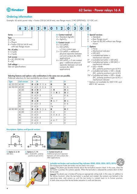
Ordering information<br />
Example: <strong>62</strong> series power relay + Faston 250 (6.3x0.8 mm), rear flange mount, 2 NO (DPST-NO), 12 V DC coil.<br />
4<br />
6 2<br />
<strong>Series</strong><br />
Type<br />
2 = PCB<br />
3 = Plug-in<br />
8 = Faston 250 (6.3x0.8 mm)<br />
with rear flange mount<br />
No. of poles<br />
2 = 2 pole<br />
3 = 3 pole<br />
Coil version<br />
8 = AC (50/60 Hz)<br />
9 = DC<br />
Coil voltage<br />
See coil specifications<br />
. 8 2 . 9 . 0 1 2 . 0 3<br />
Type Coil version A B C D<br />
<strong>62</strong>.22/23 AC-DC 0 - 4 0 - 3 - 5 - 6 0 0<br />
<strong>62</strong>.32/33 AC-DC 0 - 4 0 - 3 - 5 - 6 0 0 - 6<br />
AC-DC 0 - 4 0 - 5 2 - 4 0 - 6<br />
AC 0 - 4 0 2 - 3 - 4 - 5 0 - 6<br />
AC 0 - 4 0 - 3 3 0 - 6<br />
AC 0 - 4 0 54 /<br />
DC 0 - 4 0 4 - 6 - 7 0 - 6<br />
DC 0 - 4 0 - 3 6 0 - 6<br />
DC 0 - 4 0 74 /<br />
<strong>62</strong>.82/83 AC-DC 0 - 4 0 - 3 - 5 - 6 0 0 - 9<br />
AC-DC 0 - 4 0 - 5 2 - 4 0<br />
AC 0 - 4 0 2 - 3 - 4 - 5 0<br />
AC 0 - 4 0 - 3 3 0<br />
DC 0 - 4 0 4 - 6 - 7 0<br />
DC 0 - 4 0 - 3 6 0<br />
A B C D<br />
A: Contact material<br />
0 = Standard AgCdO<br />
4 = AgSnO2 B: Contact circuit<br />
0 = CO (nPDT)<br />
3 = NO (nPST),<br />
≥ 3 mm contact gap<br />
5 = CO (nPDT) + additional<br />
physical separator between<br />
coil and contacts (for SELV<br />
applications)<br />
6 = NO (nPST), ≥ 3 mm contact<br />
gap + additional physical<br />
separator between coil and<br />
contacts (for SELV<br />
applications)<br />
Selecting features and options: only combinations in the same row are possible.<br />
Preferred selections for best availability are shown in bold.<br />
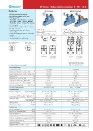
Descriptions: Options and Special versions<br />
C: Option 3, 5, 54<br />
LED (AC)<br />
1<br />
C: Option 6, 7, 74<br />
LED + diode (DC, polarity<br />
positive to pin A/A1)<br />
2<br />
3<br />
B: Contact circuit 5, 6<br />
Additional physical separator<br />
between coil and contacts (for<br />
SELV applications)<br />
<strong>62</strong> <strong>Series</strong> - <strong>Power</strong> <strong>relays</strong> <strong>16</strong> A<br />
0 0<br />
D: Special versions<br />
0 = Standard<br />
6 = Rear flange mount<br />
9 = Type <strong>62</strong>.82/83 without rear flange<br />
mount<br />
C: Options<br />
0 = None<br />
2 = Mechanical indicator<br />
3 = LED (AC)<br />
4 = Lockable test button +<br />
mechanical indicator<br />
5* = Lockable test button + LED (AC)<br />
54* = Lockable test button + LED (AC) +<br />
mechanical indicator<br />
6* = LED + diode<br />
(DC, polarity positive to pin A/A1)<br />
7* = Lockable test button + LED + diode<br />
(DC, polarity positive to pin A/A1)<br />
74* = Lockable test button + LED + diode<br />
(DC, polarity positive to pin A/A1) +<br />
mechanical indicator<br />
* Options not available for 220 V DC and<br />
400 V AC versions.<br />
Lockable test button and mechanical flag indicator (0040, 0050, 0054, 0070, 0074)<br />
The dual-purpose <strong>Finder</strong> test button can be used in two ways:<br />
Case 1) The plastic pip (located directly above the test button) remains intact. In this case, when the<br />
test button is pushed, the contacts operate. When the test button is released the contacts return to their<br />
former state.<br />
Case 2) The plastic pip is broken-off (using an appropriate cutting tool). In this case, (in addition to<br />
the above function), when the test button is pushed and rotated, the contacts are latched in the<br />
operating state, and remain so until the test button is rotated back to its former position.<br />
In both cases ensure that the test button actuation is swift and decisive.<br />
P A T E N T<br />
E U R O P E A N E U R O P E A N