Features 62 Series - Power relays 16 A - Finder
Features 62 Series - Power relays 16 A - Finder
Features 62 Series - Power relays 16 A - Finder

Create successful ePaper yourself
Turn your PDF publications into a flip-book with our unique Google optimized e-Paper software.
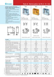
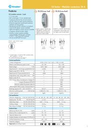
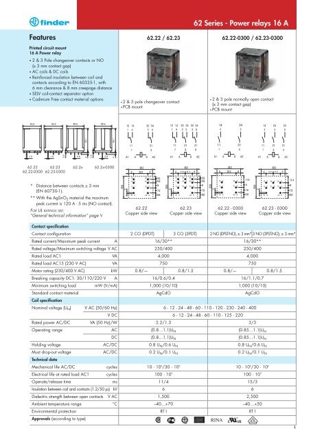
<strong>Features</strong><br />
Printed circuit mount<br />
<strong>16</strong> A <strong>Power</strong> relay<br />
2 & 3 Pole changeover contacts or NO<br />
(≥ 3 mm contact gap)<br />
AC coils & DC coils<br />
Reinforced insulation between coil and<br />
contacts according to EN 60335-1, with<br />
6 mm clearance & 8 mm creepage distance<br />
SELV coil-contact separator option<br />
Cadmium Free contact material options<br />
<strong>62</strong>.22<br />
<strong>62</strong>.22-0300<br />
<strong>62</strong>.23<br />
<strong>62</strong>.23-0300<br />
<strong>62</strong>.2x<br />
<strong>62</strong>.2x-0300<br />
* Distance between contacts ≥ 3 mm<br />
(EN 60730-1).<br />
** With the AgSnO2 material the maximum<br />
peak current is 120 A - 5 ms (NO contact).<br />
FOR UL RATINGS SEE:<br />
“General technical information” page V<br />
Contact specification<br />
Contact configuration<br />
Rated current/Maximum peak current A<br />
Rated voltage/Maximum switching voltage V AC<br />
Rated load AC1 VA<br />
Rated load AC15 (230 V AC) VA<br />
Motor rating (230/400 V AC) kW<br />
Breaking capacity DC1: 30/110/220 V A<br />
Minimum switching load<br />
Standard contact material<br />
Coil specification<br />
mW (V/mA)<br />
Nominal voltage (UN) V AC (50/60 Hz)<br />
V DC<br />
Rated power AC/DC VA (50 Hz)/W<br />
Operating range AC<br />
DC<br />
Holding voltage AC/DC<br />
Must drop-out voltage<br />
Technical data<br />
AC/DC<br />
Mechanical life AC/DC cycles<br />
Electrical life at rated load AC1 cycles<br />
Operate/release time ms<br />
Insulation between coil and contacts (1.2/50 µs) kV<br />
Dielectric strength between open contacts V AC<br />
Ambient temperature range<br />
Environmental protection<br />
Approvals (according to type)<br />
°C<br />
<strong>62</strong>.22 / <strong>62</strong>.23 <strong>62</strong>.22-0300 / <strong>62</strong>.23-0300<br />
2 & 3 pole changeover contact<br />
PCB mount<br />
<strong>62</strong> <strong>Series</strong> - <strong>Power</strong> <strong>relays</strong> <strong>16</strong> A<br />
2 & 3 pole normally open contact<br />
(≥ 3 mm contact gap)<br />
PCB mount<br />
<strong>62</strong>.22 <strong>62</strong>.23 <strong>62</strong>.22 - 0300 <strong>62</strong>.23 - 0300<br />
Copper side view Copper side view Copper side view Copper side view<br />
2 CO (DPDT) 3 CO (3PDT) 2 NO (DPST-NO), ≥ 3 mm* 3 NO (3PST-NO), ≥ 3 mm*<br />
<strong>16</strong>/30** <strong>16</strong>/30**<br />
250/400 250/400<br />
4,000 4,000<br />
750 750<br />
0.8/— 0.8/1.5 0.8/— 0.8/1.5<br />
<strong>16</strong>/0.6/0.4 <strong>16</strong>/1.1/0.7<br />
1,000 (10/10) 1,000 (10/10)<br />
AgCdO AgCdO<br />
6 - 12 - 24 - 48 - 60 - 110 - 120 - 230 - 240 - 400<br />
6 - 12 - 24 - 48 - 60 - 110 - 125 - 220<br />
2.2/1.3 3/3<br />
(0.8…1.1)UN (0.85…1.1)UN (0.8…1.1)UN (0.85…1.1)UN 0.8 UN/0.6 UN 0.8 UN/0.6 UN 0.2 UN/0.1 UN 0.2 UN/0.1 UN 10 · 10 6 /30 · 10 6<br />
10 · 10 6 /30 · 10 6<br />
100 · 10 3<br />
100 · 10 3<br />
11/4 15/3<br />
6 6<br />
1,500 2,500<br />
–40…+70 –40…+50<br />
RT I RT I<br />
1
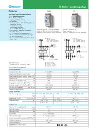
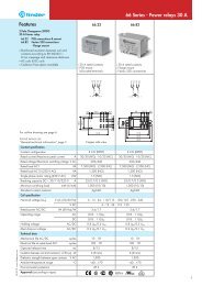
<strong>Features</strong><br />
Plug-in mount/Faston 187<br />
<strong>16</strong> A <strong>Power</strong> relay<br />
Plug-in (92 series sockets) or Faston 187<br />
(4.8x0.5 mm) with optional mounting adaptors<br />
2 & 3 Pole changeover contacts or NO<br />
(≥ 3 mm contact gap)<br />
AC coils & DC coils<br />
UL Listing (certain relay/socket combinations)<br />
LED, mechanical indicator & test button options<br />
Reinforced insulation between coil and<br />
contacts according to EN 60335-1, with<br />
6 mm clearance & 8 mm creepage distance<br />
SELV coil-contact separator option<br />
Cadmium Free contact material options<br />
Sockets and accessories<br />
European Patent<br />
<strong>62</strong>.32 <strong>62</strong>.33<br />
<strong>62</strong>.32-0300 <strong>62</strong>.33-0300<br />
* Distance between contacts ≥ 3 mm (EN 60730-1).<br />
** With the AgSnO2 material the maximum<br />
peak current is 120 A - 5 ms (NO contact).<br />
FOR UL RATINGS SEE:<br />
“General technical information” page V<br />
Contact specification<br />
Contact configuration<br />
Rated current/Maximum peak current A<br />
Rated voltage/Maximum switching voltage V AC<br />
Rated load AC1 VA<br />
Rated load AC15 (230 V AC) VA<br />
Motor rating (230/400 V AC) kW<br />
Breaking capacity DC1: 30/110/220 V A<br />
Minimum switching load<br />
Standard contact material<br />
Coil specification<br />
mW (V/mA)<br />
Nominal voltage (UN) V AC (50/60 Hz)<br />
V DC<br />
Rated power AC/DC VA (50 Hz)/W<br />
Operating range AC<br />
DC<br />
Holding voltage AC/DC<br />
Must drop-out voltage<br />
Technical data<br />
AC/DC<br />
Mechanical life AC/DC cycles<br />
Electrical life at rated load AC1 cycles<br />
Operate/release time ms<br />
Insulation between coil and contacts (1.2/50 µs) kV<br />
Dielectric strength between open contacts V AC<br />
Ambient temperature range<br />
Environmental protection<br />
Approvals (according to type)<br />
°C<br />
2<br />
<strong>62</strong>.3x<br />
<strong>62</strong>.3x-0300<br />
<strong>62</strong>.32 / <strong>62</strong>.33 <strong>62</strong>.32-0300 / <strong>62</strong>.33-0300<br />
2 & 3 pole changeover contact<br />
Plug-in / Faston 187<br />
<strong>62</strong> <strong>Series</strong> - <strong>Power</strong> <strong>relays</strong> <strong>16</strong> A<br />
2 & 3 pole normally open contact<br />
(≥ 3 mm contact gap)<br />
Plug-in / Faston 187<br />
<strong>62</strong>.32 <strong>62</strong>.33 <strong>62</strong>.32-0300 <strong>62</strong>.33-0300<br />
2 CO (DPDT) 3 CO (3PDT) 2 NO (DPST-NO), ≥ 3 mm* 3 NO (3PST-NO), ≥ 3 mm*<br />
<strong>16</strong>/30** <strong>16</strong>/30**<br />
250/400 250/400<br />
4,000 4,000<br />
750 750<br />
0.8/— 0.8/1.5 0.8/— 0.8/1.5<br />
<strong>16</strong>/0.6/0.4 <strong>16</strong>/1.1/0.7<br />
1,000 (10/10) 1,000 (10/10)<br />
AgCdO AgCdO<br />
6 - 12 - 24 - 48 - 60 - 110 - 120 - 230 - 240 - 400<br />
6 - 12 - 24 - 48 - 60 - 110 - 125 - 220<br />
2.2/1.3 3/3<br />
(0.8…1.1)UN (0.85…1.1)UN (0.8…1.1)UN (0.85…1.1)UN 0.8 UN/0.6 UN 0.8 UN/0.6 UN 0.2 UN/0.1 UN 0.2 UN/0.1 UN 10 · 10 6 /30 · 10 6<br />
10 · 10 6 /30 · 10 6<br />
100 · 10 3<br />
100 · 10 3<br />
11/4 15/3<br />
6 6<br />
1,500 2,500<br />
–40…+70 –40…+50<br />
RT I RT I
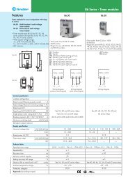
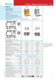
<strong>Features</strong><br />
Flange mount/Faston 250<br />
<strong>16</strong> A <strong>Power</strong> relay<br />
<strong>62</strong>.82<br />
<strong>62</strong>.82-0300<br />
Faston 250 (6.3x0.8 mm) termination Flange<br />
or optional mounting adaptors<br />
2 & 3 Pole changeover contacts or NO<br />
(≥ 3 mm contact gap)<br />
AC coils & DC coils<br />
LED, mechanical indicator & test button options<br />
Reinforced insulation between coil and<br />
contacts according to EN 60335-1, with<br />
6 mm clearance & 8 mm creepage distance<br />
SELV coil-contact separator option<br />
Cadmium Free contact material options<br />
European Patent<br />
<strong>62</strong>.83<br />
<strong>62</strong>.83-0300<br />
<strong>62</strong>.8x<br />
<strong>62</strong>.8x-0300<br />
* Distance between contacts ≥ 3 mm<br />
(EN 60730-1).<br />
** With the AgSnO2 material the maximum<br />
peak current is 120 A - 5 ms (NO contact).<br />
FOR UL RATINGS SEE:<br />
“General technical information” page V<br />
Contact specification<br />
Contact configuration<br />
Rated current/Maximum peak current A<br />
Rated voltage/Maximum switching voltage V AC<br />
Rated load AC1 VA<br />
Rated load AC15 (230 V AC) VA<br />
Motor rating (230/400 V AC) kW<br />
Breaking capacity DC1: 30/110/220 V A<br />
Minimum switching load<br />
Standard contact material<br />
Coil specification<br />
mW (V/mA)<br />
Nominal voltage (UN) V AC (50/60 Hz)<br />
V DC<br />
Rated power AC/DC VA (50 Hz)/W<br />
Operating range AC<br />
DC<br />
Holding voltage AC/DC<br />
Must drop-out voltage<br />
Technical data<br />
AC/DC<br />
Mechanical life AC/DC cycles<br />
Electrical life at rated load AC1 cycles<br />
Operate/release time ms<br />
Insulation between coil and contacts (1.2/50 µs) kV<br />
Dielectric strength between open contacts V AC<br />
Ambient temperature range<br />
Environmental protection<br />
Approvals (according to type)<br />
°C<br />
<strong>62</strong>.82 / <strong>62</strong>.83 <strong>62</strong>.82-0300 / <strong>62</strong>.83-0300<br />
2 & 3 pole changeover contact<br />
Flange mount / Faston 250<br />
<strong>62</strong> <strong>Series</strong> - <strong>Power</strong> <strong>relays</strong> <strong>16</strong> A<br />
2 & 3 pole normally open contact<br />
(≥ 3 mm contact gap)<br />
Flange mount / Faston 250<br />
<strong>62</strong>.82 <strong>62</strong>.83 <strong>62</strong>.82-0300 <strong>62</strong>.83-0300<br />
2 CO (DPDT) 3 CO (3PDT) 2 NO (DPST-NO), ≥ 3 mm* 3 NO (3PST-NO), ≥ 3 mm*<br />
<strong>16</strong>/30** <strong>16</strong>/30**<br />
250/400 250/400<br />
4,000 4,000<br />
750 750<br />
0.8/— 0.8/1.5 0.8/— 0.8/1.5<br />
<strong>16</strong>/0.6/0.4 <strong>16</strong>/1.1/0.7<br />
1,000 (10/10) 1,000 (10/10)<br />
AgCdO AgCdO<br />
6 - 12 - 24 - 48 - 60 - 110 - 120 - 230 - 240 - 400<br />
6 - 12 - 24 - 48 - 60 - 110 - 125 - 220<br />
2.2/1.3 3/3<br />
(0.8…1.1)UN (0.85…1.1)UN (0.8…1.1)UN (0.85…1.1)UN 0.8 UN/0.6 UN 0.8 UN/0.6 UN 0.2 UN/0.1 UN 0.2 UN/0.1 UN 10 · 10 6 /30 · 10 6<br />
10 · 10 6 /30 · 10 6<br />
100 · 10 3<br />
100 · 10 3<br />
11/4 15/3<br />
6 6<br />
1,500 2,500<br />
–40…+70 –40…+50<br />
RT I RT I<br />
3
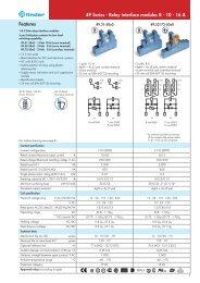
Ordering information<br />
Example: <strong>62</strong> series power relay + Faston 250 (6.3x0.8 mm), rear flange mount, 2 NO (DPST-NO), 12 V DC coil.<br />
4<br />
6 2<br />
<strong>Series</strong><br />
Type<br />
2 = PCB<br />
3 = Plug-in<br />
8 = Faston 250 (6.3x0.8 mm)<br />
with rear flange mount<br />
No. of poles<br />
2 = 2 pole<br />
3 = 3 pole<br />
Coil version<br />
8 = AC (50/60 Hz)<br />
9 = DC<br />
Coil voltage<br />
See coil specifications<br />
. 8 2 . 9 . 0 1 2 . 0 3<br />
Type Coil version A B C D<br />
<strong>62</strong>.22/23 AC-DC 0 - 4 0 - 3 - 5 - 6 0 0<br />
<strong>62</strong>.32/33 AC-DC 0 - 4 0 - 3 - 5 - 6 0 0 - 6<br />
AC-DC 0 - 4 0 - 5 2 - 4 0 - 6<br />
AC 0 - 4 0 2 - 3 - 4 - 5 0 - 6<br />
AC 0 - 4 0 - 3 3 0 - 6<br />
AC 0 - 4 0 54 /<br />
DC 0 - 4 0 4 - 6 - 7 0 - 6<br />
DC 0 - 4 0 - 3 6 0 - 6<br />
DC 0 - 4 0 74 /<br />
<strong>62</strong>.82/83 AC-DC 0 - 4 0 - 3 - 5 - 6 0 0 - 9<br />
AC-DC 0 - 4 0 - 5 2 - 4 0<br />
AC 0 - 4 0 2 - 3 - 4 - 5 0<br />
AC 0 - 4 0 - 3 3 0<br />
DC 0 - 4 0 4 - 6 - 7 0<br />
DC 0 - 4 0 - 3 6 0<br />
A B C D<br />
A: Contact material<br />
0 = Standard AgCdO<br />
4 = AgSnO2 B: Contact circuit<br />
0 = CO (nPDT)<br />
3 = NO (nPST),<br />
≥ 3 mm contact gap<br />
5 = CO (nPDT) + additional<br />
physical separator between<br />
coil and contacts (for SELV<br />
applications)<br />
6 = NO (nPST), ≥ 3 mm contact<br />
gap + additional physical<br />
separator between coil and<br />
contacts (for SELV<br />
applications)<br />
Selecting features and options: only combinations in the same row are possible.<br />
Preferred selections for best availability are shown in bold.<br />
Descriptions: Options and Special versions<br />
C: Option 3, 5, 54<br />
LED (AC)<br />
1<br />
C: Option 6, 7, 74<br />
LED + diode (DC, polarity<br />
positive to pin A/A1)<br />
2<br />
3<br />
B: Contact circuit 5, 6<br />
Additional physical separator<br />
between coil and contacts (for<br />
SELV applications)<br />
<strong>62</strong> <strong>Series</strong> - <strong>Power</strong> <strong>relays</strong> <strong>16</strong> A<br />
0 0<br />
D: Special versions<br />
0 = Standard<br />
6 = Rear flange mount<br />
9 = Type <strong>62</strong>.82/83 without rear flange<br />
mount<br />
C: Options<br />
0 = None<br />
2 = Mechanical indicator<br />
3 = LED (AC)<br />
4 = Lockable test button +<br />
mechanical indicator<br />
5* = Lockable test button + LED (AC)<br />
54* = Lockable test button + LED (AC) +<br />
mechanical indicator<br />
6* = LED + diode<br />
(DC, polarity positive to pin A/A1)<br />
7* = Lockable test button + LED + diode<br />
(DC, polarity positive to pin A/A1)<br />
74* = Lockable test button + LED + diode<br />
(DC, polarity positive to pin A/A1) +<br />
mechanical indicator<br />
* Options not available for 220 V DC and<br />
400 V AC versions.<br />
Lockable test button and mechanical flag indicator (0040, 0050, 0054, 0070, 0074)<br />
The dual-purpose <strong>Finder</strong> test button can be used in two ways:<br />
Case 1) The plastic pip (located directly above the test button) remains intact. In this case, when the<br />
test button is pushed, the contacts operate. When the test button is released the contacts return to their<br />
former state.<br />
Case 2) The plastic pip is broken-off (using an appropriate cutting tool). In this case, (in addition to<br />
the above function), when the test button is pushed and rotated, the contacts are latched in the<br />
operating state, and remain so until the test button is rotated back to its former position.<br />
In both cases ensure that the test button actuation is swift and decisive.<br />
P A T E N T<br />
E U R O P E A N E U R O P E A N
Technical data<br />
Insulation according to EN 61810-1<br />
<strong>62</strong> <strong>Series</strong> - <strong>Power</strong> <strong>relays</strong> <strong>16</strong> A<br />
2 CO - 3 CO 2 NO - 3 NO<br />
Nominal voltage of supply system V AC 230/400 230/400<br />
Rated insulation voltage V AC 400 400<br />
Pollution degree 3 3<br />
Insulation between coil and contact set<br />
Type of insulation Reinforced Reinforced<br />
Overvoltage category III III<br />
Rated impulse voltage kV (1.2/50 µs) 6 6<br />
Dielectric strength V AC 4,000 4,000<br />
Insulation between adjacent contacts<br />
Type of insulation Basic Basic<br />
Overvoltage category III III<br />
Rated impulse voltage kV (1.2/50 µs) 4 4<br />
Dielectric strength V AC 2,500 2,500<br />
Insulation between open contacts<br />
Type of disconnection Micro-disconnection Full-disconnection<br />
Overvoltage category — III<br />
Rated impulse voltage kV (1.2/50 µs) — 4<br />
Dielectric strength<br />
Conducted disturbance immunity<br />
V AC/kV (1.2/50 µs) 1,500/2 2,500/4<br />
Burst (5...50)ns, 5 kHz, on A1 - A2 EN 61000-4-4 level 4 (4 kV)<br />
Surge (1.2/50 µs) on A1 - A2 (differential mode)<br />
Other data<br />
EN 61000-4-5 level 4 (4 kV)<br />
Bounce time: NO/NC ms 1/5 (changeover) 3/— (normally open)<br />
Vibration resistance (10…150)Hz: NO/NC g 20/8<br />
Shock resistance g 15<br />
<strong>Power</strong> lost to the environment 2 pole (CO) 3 pole (CO) 2 pole (NO) 3 pole (NO)<br />
without contact current W 1.3 1.3 3 3<br />
with rated current W 3.3 4.3 5 6<br />
Recommended distance between <strong>relays</strong> mounted on PCB mm ≥ 5<br />
5
Contact specification<br />
F <strong>62</strong> - Electrical life (AC) v contact current<br />
6<br />
Cycles<br />
H <strong>62</strong> - Maximum DC1 breaking capacity<br />
Changeover contacts<br />
DC breaking current (A)<br />
Resistive load - cosϕ = 1<br />
Inductive load - cosϕ = 0.4<br />
contacts in series<br />
Voltage DC (V)<br />
H <strong>62</strong> - Maximum DC1 breaking capacity<br />
Normally open contacts<br />
DC breeaking current (A)<br />
<strong>62</strong> <strong>Series</strong> - <strong>Power</strong> <strong>relays</strong> <strong>16</strong> A<br />
contacts in series<br />
Voltage DC (V)<br />
When switching a resistive load (DC1) having voltage and current values under the curve, an electrical life of ≥ 100·10 3 can be expected.<br />
In the case of DC13 loads, the connection of a diode in parallel with the load will permit a similar electrical life as for a DC1 load.<br />
Note: the release time of the load will be increased.
Coil specifications<br />
DC version data<br />
Nominal Coil Operating range Resistance Rated coil<br />
voltage code consumption<br />
U N U min U max R I at U N<br />
V V V Ω mA<br />
6 9.006 4.8 6.6 28 214<br />
12 9.012 9.6 13.2 110 109<br />
24 9.024 19.2 26.4 445 54<br />
48 9.048 38.4 52.8 1,770 27<br />
60 9.060 48 66 2,760 21.7<br />
110 9.110 88 121 9,420 11.7<br />
125 9.125 100 138 12,000 10.4<br />
220 9.220 176 242 37,300 5.8<br />
Nominal Coil Operating range Resistance Rated coil<br />
voltage code consumption<br />
U N U min U max R I at U N<br />
V V V Ω mA<br />
6 9.006 5.1 6.6 12 500<br />
12 9.012 10.2 13.2 48 250<br />
24 9.024 20.4 26.4 192 125<br />
48 9.048 40.8 52.8 770 63<br />
60 9.060 51 66 1,200 50<br />
110 9.110 93.5 121 4,200 26<br />
125 9.125 106 138 5,200 24<br />
220 9.220 187 242 17,600 12.5<br />
AC version data<br />
<strong>62</strong> <strong>Series</strong> - <strong>Power</strong> <strong>relays</strong> <strong>16</strong> A<br />
Nominal Coil Operating range Resistance Rated coil<br />
voltage code consumption<br />
U N U min U max R I at U N (50Hz)<br />
V V V Ω mA<br />
6 8.006 4.8 6.6 4.6 367<br />
12 8.012 9.6 13.2 19 183<br />
24 8.024 19.2 26.4 74 90<br />
48 8.048 38.4 52.8 290 47<br />
60 8.060 48 66 450 37<br />
110 8.110 88 121 1,600 20<br />
120 8.120 96 132 1,940 18.6<br />
230 8.230 184 253 7,250 10.5<br />
240 8.240 192 264 8,500 9.2<br />
400 8.400 320 440 19,800 6<br />
DC (NO/nPST-NO) version data - ≥ 3 mm AC (NO/nPST-NO) version data - ≥ 3 mm<br />
R <strong>62</strong> - DC coil operating range v ambient temperature<br />
Changeover contacts<br />
R <strong>62</strong> - DC coil operating range v ambient temperature<br />
Normally open contacts<br />
1 - Max. permitted coil voltage.<br />
2 - Min. pick-up voltage with coil at ambient temperature.<br />
Nominal Coil Operating range Resistance Rated coil<br />
voltage code consumption<br />
U N U min U max R I at U N (50Hz)<br />
V V V Ω mA<br />
6 8.006 5.1 6.6 4 540<br />
12 8.012 10.2 13.2 14 275<br />
24 8.024 20.4 26.4 <strong>62</strong> 130<br />
48 8.048 40.8 52.8 220 70<br />
60 8.060 51 66 348 55<br />
110 8.110 93.5 121 1,200 30<br />
120 8.120 106 137 1,350 24<br />
230 8.230 196 253 5,000 14<br />
240 8.240 204 264 6,300 12.5<br />
400 8.400 340 440 14,700 7.8<br />
R <strong>62</strong> - AC coil operating range v ambient temperature<br />
Changeover contacts<br />
R <strong>62</strong> - AC coil operating range v ambient temperature<br />
Normally open contacts<br />
1 - Max. permitted coil voltage.<br />
2 - Min. pick-up voltage with coil at ambient temperature.<br />
7
Accessories<br />
0<strong>62</strong>.10<br />
0<strong>62</strong>.10 with relay<br />
0<strong>62</strong>.60<br />
0<strong>62</strong>.60 with relay<br />
8<br />
0<strong>62</strong>.05<br />
<strong>62</strong> <strong>Series</strong> - <strong>Power</strong> <strong>relays</strong> <strong>16</strong> A<br />
Mounting adaptor for types <strong>62</strong>.3x and <strong>62</strong>.8x.xxxx.xxx9 (M4) 0<strong>62</strong>.10<br />
0<strong>62</strong>.10<br />
0<strong>62</strong>.10 with relay<br />
Flange mounting adaptor for types <strong>62</strong>.3x and <strong>62</strong>.8x.xxxx.xxx9 0<strong>62</strong>.60<br />
0<strong>62</strong>.60<br />
0<strong>62</strong>.60 with relay<br />
Top flange mount for types <strong>62</strong>.3x and <strong>62</strong>.8x.xxxx.xxx9 0<strong>62</strong>.05<br />
0<strong>62</strong>.05 with relay 0<strong>62</strong>.05 0<strong>62</strong>.05 with relay<br />
0<strong>62</strong>.07<br />
0<strong>62</strong>.07 with relay<br />
Top 35 mm rail (EN 60715) mount for types <strong>62</strong>.3x and <strong>62</strong>.8x.xxxx.xxx9 0<strong>62</strong>.07<br />
0<strong>62</strong>.07 0<strong>62</strong>.07 with relay
Accessories<br />
0<strong>62</strong>.08<br />
<strong>62</strong> <strong>Series</strong> - <strong>Power</strong> <strong>relays</strong> <strong>16</strong> A<br />
Rear 35 mm rail (EN 60715) mount for types <strong>62</strong>.3x and <strong>62</strong>.8x.xxxx.xxx9 0<strong>62</strong>.08<br />
0<strong>62</strong>.08 with relay 0<strong>62</strong>.08 0<strong>62</strong>.08 with relay<br />
060.72<br />
Sheet of marker tags for <strong>62</strong> series <strong>relays</strong>, plastic, 72 tags, 6x12 mm 060.72<br />
9
92.03<br />
Approvals<br />
(according to type):<br />
L 92 - Rated current vs ambient temperature<br />
Rated current (A)<br />
86.00<br />
86.30<br />
99.02<br />
Approvals<br />
(according to type):<br />
DC Modules with<br />
non-standard polarity<br />
(+A2) on request.<br />
10<br />
92 <strong>Series</strong> - Sockets and accessories for <strong>62</strong> series <strong>relays</strong><br />
Screw terminal (Box clamp) socket 92.03 92.03.0<br />
panel or 35 mm rail (EN 60715) mount Blue Black<br />
For relay type <strong>62</strong>.32, <strong>62</strong>.33<br />
Accessories<br />
Metal retaining clip (supplied with socket - packaging code SMA) 092.71<br />
Identification tag 092.00.2<br />
Modules (see table below) 99.02<br />
Timer modules (see table below) 86.00, 86.30<br />
Technical data<br />
Rated values <strong>16</strong> A - 250 V<br />
Dielectric strength 6 kV (1.2/50 µs) between coil and contacts<br />
Protection category IP 20<br />
Ambient temperature °C –40…+70 (see diagram L92)<br />
Screw torque Nm 0.8<br />
Wire strip length mm 10<br />
Max. wire size for 92.03 socket solid wire stranded wire<br />
mm 2 1x10 / 2x4 1x6 / 2x4<br />
AWG 1x8 / 2x12 1x10 / 2x12<br />
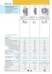
86 series timer modules<br />
Multi-voltage: (12…240)V AC/DC;<br />
Multi-functions: AI, DI, SW, BE, CE, DE, EE, FE; (0.05s…100h) 86.00.0.240.0000<br />
(12…24)V AC/DC; Bi-function: AI, DI; (0.05s…100h) 86.30.0.024.0000<br />
(110...125)V AC; Bi-function: AI, DI; (0.05s…100h) 86.30.8.120.0000<br />
(230...240)V AC; Bi-function: AI, DI; (0.05s…100h) 86.30.8.240.0000<br />
Approvals<br />
(according to type):<br />
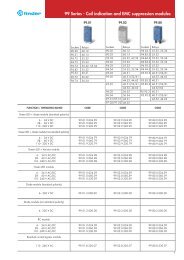
99.02 coil indication and EMC suppression modules for 92.03 socket<br />
Diode (+A1, standard polarity) (6...220)V DC 99.02.3.000.00<br />
LED (6...24)V DC/AC 99.02.0.024.59<br />
LED (28...60)V DC/AC 99.02.0.060.59<br />
LED (110...240)V DC/AC 99.02.0.230.59<br />
LED + Diode (+A1, standard polarity) (6...24)V DC 99.02.9.024.99<br />
LED + Diode (+A1, standard polarity) (28...60)V DC 99.02.9.060.99<br />
LED + Diode (+A1, standard polarity) (110...220)V DC 99.02.9.220.99<br />
LED + Varistor (6...24)V DC/AC 99.02.0.024.98<br />
LED + Varistor (28...60)V DC/AC 99.02.0.060.98<br />
LED + Varistor (110...240)V DC/AC 99.02.0.230.98<br />
RC circuit (6...24)V DC/AC 99.02.0.024.09<br />
RC circuit (28...60)V DC/AC 99.02.0.060.09<br />
RC circuit (110...240)V DC/AC 99.02.0.230.09<br />
Residual current by-pass (110...240)V AC 99.02.8.230.07
92.13<br />
Approvals<br />
(according to type):<br />
92.33<br />
Approvals<br />
(according to type):<br />
Packaging code<br />
92 <strong>Series</strong> - Sockets and accessories for <strong>62</strong> series <strong>relays</strong><br />
PCB socket 92.13 (blue) 92.13.0 (black)<br />
For relay type <strong>62</strong>.32, <strong>62</strong>.33<br />
Accessories<br />
Metal retaining clip (supplied with socket - packaging code SMA) 092.54<br />
Technical data<br />
Rated values 10 A - 250 V<br />
Dielectric strength 2.5 kV AC<br />
Ambient temperature °C –40…+70<br />
<strong>62</strong>.3x plug on 92.13 is 63.3 mm high<br />
Panel mount solder socket mounted with M3 screw 92.33 (blue)<br />
For relay type <strong>62</strong>.32, <strong>62</strong>.33<br />
Accessories<br />
Metal retaining clip (supplied with socket - packaging code SMA) 092.54<br />
Technical data<br />
Rated values 10 A - 250 V<br />
Dielectric strength 2.5 kV AC<br />
Ambient temperature °C –40…+70<br />
How to code and identify retaining clip and packaging options for sockets.<br />
Example:<br />
9 2<br />
9 2<br />
.<br />
.<br />
0 3<br />
0 3<br />
S M A<br />
A Standard packaging<br />
SM Metal retaining clip<br />
Without retaining clip<br />
11