DETAILING STAIRS: - AISC
DETAILING STAIRS: - AISC
DETAILING STAIRS: - AISC

Create successful ePaper yourself
Turn your PDF publications into a flip-book with our unique Google optimized e-Paper software.
Modern Steel Construction / October 1999<br />
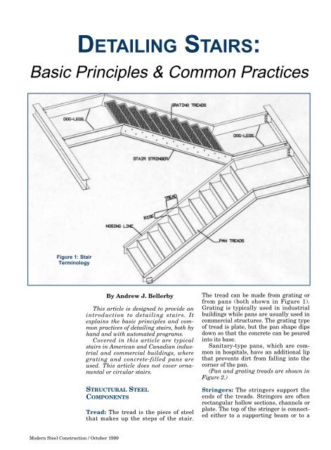
<strong>DETAILING</strong> <strong>STAIRS</strong>:<br />
Basic Principles & Common Practices<br />
Figure 1: Stair<br />
Terminology<br />
By Andrew J. Bellerby<br />
This article is designed to provide an<br />
introduction to detailing stairs. It<br />
explains the basic principles and common<br />
practices of detailing stairs, both by<br />
hand and with automated programs.<br />
Covered in this article are typical<br />
stairs in American and Canadian industrial<br />
and commercial buildings, where<br />
grating and concrete-filled pans are<br />
used. This article does not cover ornamental<br />
or circular stairs.<br />
STRUCTURAL STEEL<br />
COMPONENTS<br />
Tread: The tread is the piece of steel<br />
that makes up the steps of the stair.<br />
The tread can be made from grating or<br />
from pans (both shown in Figure 1).<br />
Grating is typically used in industrial<br />
buildings while pans are usually used in<br />
commercial structures. The grating type<br />
of tread is plate, but the pan shape dips<br />
down so that the concrete can be poured<br />
into its base.<br />
Sanitary-type pans, which are common<br />
in hospitals, have an additional lip<br />
that prevents dirt from falling into the<br />
corner of the pan.<br />
(Pan and grating treads are shown in<br />
Figure 2.)<br />
Stringers: The stringers support the<br />
ends of the treads. Stringers are often<br />
rectangular hollow sections, channels or<br />
plate. The top of the stringer is connected<br />
either to a supporting beam or to a
dog leg (see Figure 3).<br />
The bottom of the stringer is connected<br />
to a supporting beam, a dog leg, or<br />
the ground. If attached to a supporting<br />
beam, the stringer can be bolted or<br />
welded. If attached to a dog leg, the<br />
stringer will be welded.<br />
Supporting Beam: The supporting<br />
beam supports the stringer or the dog<br />
leg (if it exists). Each stringer can be<br />
independently supported. Alternately,<br />
both stringers can be supported with<br />
the same supporting beam. The supporting<br />
beams are usually wide flange<br />
sections or channels.<br />
Dog legs: The location of the supporting<br />
beams determines whether dog legs<br />
are actually needed (as shown in Figure<br />
4). A dog leg is needed when a viable<br />
connection cannot be made to the supporting<br />
beam directly from the stringer.<br />
The dog leg can be the support for the<br />
landing at the top of the stair, if one<br />
exists.<br />
Special pans: These are required at<br />
the top and bottom of a pan stair. One<br />
special pan closes the stair against the<br />
concrete or platform, and the other pan<br />
closes off the top of the stair (see Figure<br />
5).<br />
Figure 4:<br />
Determining<br />
whether a dog-leg<br />
is required<br />
Figure 2: Grating and<br />
Pan Threads<br />
Figure 3:<br />
Typical<br />
Stringer &<br />
Dog Leg<br />
Connection<br />
Modern Steel Construction / October 1999
Modern Steel Construction / October 1999<br />
Figure 5: Special<br />
pans at top and<br />
bottom of stair<br />
Figure 6: Stringer<br />
offset (T.O.S. to<br />
Nosing Line)<br />
LOCATION<br />
The main parameters for<br />
locating the stairs are:<br />
• Rise and tread<br />
Nosing points and nosing line<br />
Stringer offset values<br />
Dog leg to nosing point height<br />
Safe rise and safe run<br />
Number of treads<br />
An explanation of these terms<br />
follows:<br />
Rise and tread: Although the<br />
actual stair step is called the<br />
tread, there is also a measurement,<br />
as shown in Figure 1,<br />
which is termed the 'tread'. This<br />
is the horizontal distance<br />
between two consecutive treads.<br />
The rise is the vertical distance<br />
between two consecutive treads.<br />
Nosing line and nosing<br />
points: In order for the stair to<br />
be set up properly, every corner<br />
of every tread should pass<br />
through a single line. That line<br />
is called the nosing line, and the<br />
corner points on the tread<br />
through which the line traverses<br />
are called the nosing points.<br />
Stringer offset value (top of<br />
steel of stringer to nosing<br />
line): As shown in Figure 6, the<br />
stringer offset is the perpendicular<br />
distance between the top of<br />
steel of the stringer and the nosing<br />
line. The stringer offset<br />
value is required for locating the<br />
stringer in space.<br />
Dog leg to nosing point<br />
height: Where dog legs are<br />
required (i.e. cases where the<br />
stringer can't directly make a<br />
viable connection to the supporting<br />
beam), it is necessary to<br />
locate the dog legs. The top dog<br />
leg to nosing point height is the<br />
distance from the top nosing<br />
point to the top of steel of the top<br />
dog leg. The bottom dog leg to<br />
nosing point height is the distance<br />
from the bottom nosing<br />
point to the top of steel of the<br />
bottom dog leg.
Safe rise and safe run: The following<br />
general guidelines are<br />
typically used for indoor stairs in<br />
insuring that the stair is safe:<br />
3 /16 maximum variation in rise<br />
or tread is allowable.<br />
2 x rise + tread should be<br />
between 24” and 25”.<br />
Rise + tread should be<br />
between 17” and 17 1 /2”.<br />
Angle of the stair should be<br />
between 20 and 50 degrees.<br />
Note: tread minimum and rise<br />
maximum, as well as other<br />
important parameters are governed<br />
by local or state codes.<br />
Number of treads: The number<br />
of treads is obtained by dividing<br />
the total rise by the safe rise, or<br />
alternately by dividing the total<br />
run by the safe run.<br />
CONNECTIONS<br />
Grating to stringer: A typical<br />
grating to stringer connection is<br />
shown in Figure 7. The grating<br />
manufacturer specifies the location<br />
of the bolt holes.<br />
Pan to stringer: A typical pan<br />
to stringer connection is shown in<br />
Figure 7. Other connection types<br />
include double angles with a<br />
square rod bent around the pan<br />
and welded to both the pan and<br />
the stringer.<br />
Stringer to dog leg: A common<br />
stringer to dog leg connection is<br />
shown in Figure 3. This is a<br />
welded connection with both<br />
ends mitered.<br />
Stringer to ground: A common<br />
stringer to concrete floor connection<br />
is shown in Figure 3.<br />
Sketch 1: Stair nosing set-out points<br />
Figure 7: Typical<br />
trtead to stringer<br />
connections<br />
Modern Steel Construction / October 1999
Modern Steel Construction / October 1999<br />
Sketch 2: Stair layout with<br />
stringer connections<br />
Sketch 3: Stair layout<br />
with detail dimensions<br />
Sketch 4: Stair layout<br />
with detail dimensions<br />
HAND <strong>DETAILING</strong> OF <strong>STAIRS</strong><br />
Information from the engineer:<br />
The detailer must first<br />
review the engineer's layout<br />
drawings to determine whether<br />
or not all the required information<br />
is present (see "Information<br />
which designers should provide<br />
to detailers"). If this information<br />
is not present then the detailer<br />
should submit an RFI to the<br />
engineer.<br />
Layout of the nosing points:<br />
If the required information is<br />
available, then the supporting<br />
steel can be drawn to scale using<br />
construction lines, and the nosing<br />
lines can be drawn. See<br />
Sketch 1.<br />
Adding the main members:<br />
Next, draw the main stringers,<br />
and if required, draw the dog<br />
legs onto the stair layout. See<br />
Figure 5 for the method of determining<br />
whether dog legs are<br />
required. Once the main members<br />
are in position then the<br />
stringer connections are detailed<br />
both to the concrete floor and / or<br />
to the supporting steel. See<br />
Sketch 2.<br />
Adding the Pans or Grating<br />
Treads: Draw in the gratings or<br />
pans along the nosing line at the<br />
calculated positions. If a pan<br />
stair is being detailed, only the<br />
top, bottom and one typical<br />
intermediate pan are required to<br />
draw the nosing line. See Sketch<br />
3.<br />
Completing the Detail: After<br />
the completion of the stair diagram<br />
the dimensions for fabrication<br />
can be calculated and added<br />
to the detail. The weights must<br />
also be calculated for the Bill of<br />
Materials to complete the stair<br />
drawing. See Sketch 4.<br />
The entire process in 2-D,<br />
including drawing the connections,<br />
can be completed in about<br />
two to three hours.
Sketch 5: General<br />
3D layout<br />
3-D <strong>STAIRS</strong><br />
Because fabrication and erection<br />
of stairs is a 3-dimensional<br />
problem, using 3-dimensional<br />
modeling can be a very useful<br />
method of detailing. In 3-D, the<br />
detailer models a physical full<br />
size representation of the structure,<br />
and the computer then<br />
automatically produces the fabrication<br />
drawings. The detailer<br />
can walk around the structure<br />
and view it from any perspective,<br />
and build any connection. Every<br />
aspect of the structure is seen on<br />
the screen in front of the detailer<br />
so potential problem areas can<br />
be eliminated immediately. The<br />
general layout for 3D stairs is<br />
shown in Sketch 5.<br />
Method of producing stairs<br />
in 3-D: A stair will usually connect<br />
either to concrete or to a<br />
steel platform, so the detailer<br />
must tell the computer which<br />
type of platform to use.<br />
The detailer specifies whether<br />
a pan or a grating tread will be<br />
used, the number of risers<br />
required, the stringer section<br />
size and the stringer offset (or<br />
distance from top of steel of<br />
stringer to the nosing line). The<br />
tread vs. rise ratio and whether<br />
the stair is generally safe (see<br />
the section on 'safe rise and safe<br />
run') are automatically determined.<br />
If a standard rise and tread<br />
are selected then the pan can be<br />
picked from a database of existing<br />
sections. If not, then the new<br />
pan section will be created automatically<br />
(an automatically modeled<br />
pan is shown in Figure 8).<br />
The detailer can specify dimensions<br />
for the tread thickness and<br />
the toe space but the tread and<br />
rise is automatically determined.<br />
From beginning to end, the<br />
entire stair, including modeling<br />
the stair, producing the drawing<br />
and drawing the connections, can<br />
be completed in less than 10 minutes.<br />
Conclusions<br />
Stairs can be detailed manually<br />
in 2D, or automatically in 3D.<br />
Although complex, manual drafting<br />
is very common and is widely<br />
used. Automatic detailing of<br />
stairs in 3D is becoming increasingly<br />
common because it is simple<br />
and fast, helps the checker<br />
(because the stair can be visualized<br />
in 3-D), and ensures a good<br />
fit and subsequent ease of erection.<br />
Information which designers<br />
should provide to detailers<br />
Number of treads and the rise<br />
(typically given as 16@6 1 /2")<br />
Stringer size and type of<br />
stringer (i.e. channel, or tube)<br />
Supporting beam sizes and<br />
positions<br />
Nosing points (if possible)<br />
Connection details (if possible)<br />
Modern Steel Construction / October 1999
Figure 8: Automatic<br />
modeling of pans<br />
Andrew J. Bellerby is the<br />
Taining and Support Manager<br />
for AceCad Software’s support<br />
and development office in Exton,<br />
PA. He can be reached via the<br />
world wide web at<br />
www.strucad.com.<br />
The authors and publisher do<br />
not warrant, and assume no liability<br />
for the accuracy or completeness<br />
of the text, or its fitness<br />
for any particular purpose. It is<br />
the responsibility of readers to<br />
apply their professional knowledge<br />
in using the information<br />
contained in this article, and if<br />
they themselves are not professional<br />
engineers to consult the<br />
professional engineer when<br />
appropriate.<br />
Modern Steel Construction / October 1999