ABOUT WINGLETS - Ultraligero.Net
ABOUT WINGLETS - Ultraligero.Net
ABOUT WINGLETS - Ultraligero.Net

Create successful ePaper yourself
Turn your PDF publications into a flip-book with our unique Google optimized e-Paper software.
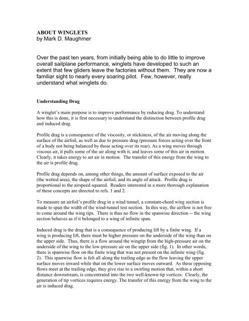
<strong>ABOUT</strong> <strong>WINGLETS</strong><br />
by Mark D. Maughmer<br />
Over the past ten years, from initially being able to do little to improve<br />
overall sailplane performance, winglets have developed to such an<br />
extent that few gliders leave the factories without them. They are now a<br />
familiar sight to nearly every soaring pilot. Few, however, really<br />
understand what winglets do.<br />
Understanding Drag<br />
A winglet’s main purpose is to improve performance by reducing drag. To understand<br />
how this is done, it is first necessary to understand the distinction between profile drag<br />
and induced drag.<br />
Profile drag is a consequence of the viscosity, or stickiness, of the air moving along the<br />
surface of the airfoil, as well as due to pressure drag (pressure forces acting over the front<br />
of a body not being balanced by those acting over its rear). As a wing moves through<br />
viscous air, it pulls some of the air along with it, and leaves some of this air in motion.<br />
Clearly, it takes energy to set air in motion. The transfer of this energy from the wing to<br />
the air is profile drag.<br />
Profile drag depends on, among other things, the amount of surface exposed to the air<br />
(the wetted area), the shape of the airfoil, and its angle of attack. Profile drag is<br />
proportional to the airspeed squared. Readers interested in a more thorough explanation<br />
of these concepts are directed to refs. 1 and 2.<br />
To measure an airfoil’s profile drag in a wind tunnel, a constant-chord wing section is<br />
made to span the width of the wind-tunnel test section. In this way, the airflow is not free<br />
to come around the wing tips. There is thus no flow in the spanwise direction -- the wing<br />
section behaves as if it belonged to a wing of infinite span.<br />
Induced drag is the drag that is a consequence of producing lift by a finite wing. If a<br />
wing is producing lift, there must be higher pressure on the underside of the wing than on<br />
the upper side. Thus, there is a flow around the wingtip from the high-pressure air on the<br />
underside of the wing to the low-pressure air on the upper side (fig. 1). In other words,<br />
there is spanwise flow on the finite wing that was not present on the infinite wing (fig.<br />
2). This spanwise flow is felt all along the trailing edge as the flow leaving the upper<br />
surface moves inward while that on the lower surface moves outward. As these opposing<br />
flows meet at the trailing edge, they give rise to a swirling motion that, within a short<br />
distance downstream, is concentrated into the two well-known tip vortices. Clearly, the<br />
generation of tip vortices requires energy. The transfer of this energy from the wing to the<br />
air is induced drag.
This process can be idealized as a “horseshoe” vortex system (fig. 3). As a consequence<br />
of producing lift, “an equal and opposite reaction” must occur -- air must be given a<br />
downward velocity, or downwash. With this downwash comes spanwise flow, tip<br />
vortices, and induced drag. The goal is to minimize this drag by minimizing the amount<br />
of energy used in producing the required downwash -- to reduce the energy that is<br />
“wasted” in creating unnecessary spanwise flow and in the rolling up of the tip<br />
vortices.<br />
In observing the flowfield around the wing in Fig.2, it should be clear that the greater the<br />
span, the less the tip effect is felt on the inboard portions of the wing. That is, the greater<br />
the span, the more “two-dimensional like” will be the rest of the wing and, consequently,<br />
the less its induced drag. As the span approaches infinity, the downwash and induced<br />
drag approach zero. Likewise, if the wing is not producing lift, there will be no<br />
downwash and thus no induced drag.<br />
It is found that the induced drag is a function of the inverse of the square of the airspeed--<br />
it is smallest at high speeds and increases as the aircraft slows down. It also depends on<br />
the weight squared divided by the span squared, (W/b) 2 , how much weight each foot of<br />
wing is asked to support. Thus, it increases with the square of the aircraft weight and<br />
decreases with the inverse of the span squared.<br />
Induced drag also depends on the wing design itself -- how efficiently it produces lift. As<br />
a reference point, the most efficient planar wing (a wing with no dihedral or a winglet) is<br />
one that has an elliptical loading (greatest at the root and decreasing toward the tip,<br />
following the equation of an ellipse). Typical planar wings are slightly less efficient,<br />
while non-planar geometries can be somewhat better than the elliptical case.<br />
Controlling Induced Drag<br />
It has been known for over a century that an endplate at the tip of a finite wing can reduce<br />
spanwise flow and induced drag. Unfortunately, to be effective at this, the endplate must<br />
be so large that the increase in skin friction drag due to excessive wetted area far<br />
outweighs the reduction in induced drag.<br />
A winglet provides a way to do better. 3 Rather than being a simple “fence,” it carries an<br />
aerodynamic load. The idea is to produce a flowfield that interacts with that of the main<br />
wing to reduce the amount of spanwise flow. That is, the spanwise induced velocities<br />
from the winglet oppose and thereby cancel those generated by the main wing.<br />
This effect has been measured experimentally (Fig. 4). Here it is observed that the<br />
spanwise flow has been largely eliminated by the presence of the winglet. In essence, the<br />
winglet diffuses or spreads out the influence of the tip vortex such that the downwash,<br />
and thereby the induced drag, is reduced. In this way, the winglet acts like an endplate in<br />
reducing the spanwise flow but, by carrying the proper aerodynamic loading, it
accomplishes this with much less wetted area. Nevertheless, recalling the penalty of<br />
profile drag with increasing airspeeds, the designer’s goal is to gain the most reduction in<br />
induced drag for the smallest increase in profile drag.<br />
The Winglet Design Process<br />
My involvement began over a decade ago when I was asked by Peter Masak to help in<br />
the design of winglets for the then-current crop of 15-meter racing sailplanes. Early<br />
design procedures were based on the idea of a crossover point -- a breakeven airspeed<br />
below which winglets improves performance by reducing induced drag and above which<br />
their extra wetted area adds enough profile drag that performance is lower. Our first<br />
successful winglets for sailplanes were guided by this notion. A trial-and-error approach<br />
was employed that eventually led to some significant improvements. 4 In 1989, one of<br />
these designs was adopted by Schempp-Hirth as the “factory winglet” for the Ventus. In<br />
retrospect, with the understanding that has come since, it seems that this process, while<br />
systematic and logical, was accompanied with a great deal of luck. It now seems<br />
somewhat remarkable that with the tool then at hand, we were able to come up with a<br />
design that worked so well.<br />
In spite of some success, I was somewhat frustrated by the lack of tools then available to<br />
analyze or design winglets. Thus, along with a succession of excellent students, a<br />
research effort was begun at Penn State to better this situation. In 1994, a collaborative<br />
research arrangement with M&H Soaring (Monty Sullivan and Heinz Weissenbueller) in<br />
Elmira, New York was begun. Their close proximity to Penn State, along with their<br />
acceptance that it would not be a trivial matter to fabricate and flight test the number of<br />
trials needed to develop and validate sound design methods, resulted in a fruitful and<br />
enjoyable cooperation that continues still.<br />
As our ability to predict the induced drag for a given wing geometry improved, 5 so did<br />
the ability to predict the effects on sailplane performance due to small changes in<br />
geometry. With this, it became possible to design winglets that much more closely<br />
achieved the intended results.<br />
Some rules-of-thumb were established. First, whether it be with up-turned tips or<br />
winglets, it can be beneficial to go “out-of-plane.” Second, while a great deal of work<br />
has been directed toward achieving the minimum induced drag, 6 our experience is that<br />
driving a winglet toward this optimum penalizes the profile drag far more than it benefits<br />
the reduction in induced drag. The design goal is clearly to minimize the overall drag,<br />
not just the induced drag.<br />
The cross-country performance of a sailplane can now be predicted with enough accuracy<br />
to determine whether small changes in winglet geometry are beneficial or not. To do<br />
this, straight flight and turning speed polars are calculated, including the influence of<br />
variations in the spanwise lift distribution over the speed range, profile drag of the
aerodynamic surfaces as they depend on Reynolds number, flap deflections, and trim<br />
drag. 7 Optimum flap settings over the speed range are also computed. These results are<br />
then used to predict average cross-country speeds in given weather conditions. After the<br />
optimum bank angles are determined for a range of thermal strengths, sizes, and lift<br />
profiles, a MacCready climb/glide analysis shows the average cross-country speed of the<br />
glider as a function of thermal strength. So rather than design the winglet to simply not<br />
hurt the lift-to-drag ratio below a certain airspeed, the winglet can be tailored to give the<br />
best cross-country performance over a wide range of operating conditions.<br />
Performance Gains: A Case Study<br />
To see the performance increases that are possible with winglets, the predicted speed<br />
polars for the Schempp-Hirth Discus 2, with and without winglets, ballasted and<br />
unballasted, are shown in Fig. 5. Although gains are demonstrated, they are difficult to<br />
assess using the polars shown. Thus, the data are replotted in terms of L/D verses<br />
velocity in Fig. 6. In addition to demonstrating the gains from carrying water ballast at<br />
higher cruising speeds, the benefit of winglets can now be seen. To get an even better<br />
idea of the gains in L/D, in Fig.7 these data are again replotted in terms of the percentage<br />
increase in L/D relative to the unballasted and ballasted glider without winglets. Note<br />
how this winglet's crossover point occurs at airspeeds that are above the maximum<br />
allowable -- there are no allowable flight conditions in this case for which the winglets<br />
penalize performance. Although a slight overall gain could be achieved by tailoring the<br />
winglet more for climb, this would result in relatively large penalties at high speeds.<br />
While the percentage gain in L/D does not appear to be very great, it is significant that it<br />
comes without any penalty at higher speeds.<br />
The effect of winglets on the percentage change in average cross-country speed relative<br />
to that of the baseline aircraft is presented in Fig. 8. The winglets improve the crosscountry<br />
performance for all the thermals considered, that is, for thermals having a 500’<br />
radius and strengths of up to 12 kts. As expected, the performance gain is very<br />
significant for weak thermals -- having winglets allows for some climb rate, whereas<br />
without them it is minimal or zero. As the thermal strengths increase, the benefits<br />
decrease; however, for this glider winglets do not hurt cross-country speed even for<br />
average thermal strengths of more than 12 kts.<br />
The point at which full water ballast becomes beneficial is indicated by the crossing of<br />
the unballasted and ballasted curves at an average thermal strength of about 8 kts,<br />
corresponding to a climb rate with full ballast that is predicted to be about 5.2 kts. In this<br />
case, “full ballast” corresponds to a wingloading of 10.6 lbs/ft 2 rather than the 9.0 lbs/ft 2<br />
allowed by U.S. Standard Class rules. As indicated, ballast causes a reduction in average<br />
cross-country speed for average thermal strengths of less than 8 kts. For thermal<br />
strengths greater than this, winglets improve the cross-country speed, but only by a halfpercent<br />
or so. The glider with winglets, however, can profitably carry ballast in slightly<br />
weaker conditions than can the glider without winglets.
Other Issues<br />
From the experience of designing winglets for a variety of sailplanes (as well as for a few<br />
non-sailplane applications), it seems that all wings can be improved with winglets,<br />
although the better the original wing from an induced drag standpoint, the smaller the<br />
gain possible with winglets (and the more difficult is the design process).<br />
It is sometimes heard that winglets were tried on a certain glider and did not work. What<br />
this really says is that a particular poor design did not work. As an example of how<br />
critical some of the design issues are, the effect of toe (incidence) angles on the Discus 2<br />
winglet design is presented in Fig. 9. Obviously, a small deviation from the optimum can<br />
cause the winglet to become a speed brake. Furthermore, each glider must have winglets<br />
specifically designed for it -- rules of thumb can be disastrous. From personal<br />
experience, there is no doubt that it is much easier to make a glider worse with winglets<br />
than it is to make it better!<br />
Winglets sometimes can fix problems of the original wing. For example, in the case of a<br />
flapped glider, it is important that the flaps/ailerons extend to the wingtip. Otherwise,<br />
when the flaps are deflected upward for high-speed cruise, the tips are loaded far more<br />
than they should be. Although only a small portion of the wing is influenced, it can result<br />
in a very significant induced drag increase. In these cases, cutting the tip back to the<br />
aileron in order to mount the winglet has resulted in unexpected gains, especially at high<br />
speeds.<br />
By understanding of how winglets achieve induced drag reduction, it also becomes clear<br />
how they can produce other performance and handling gains. In particular, it has been<br />
found that winglets improve the flow in the tip region and thereby improve the<br />
effectiveness of the ailerons. This is in part due to the local angle of attack in the vicinity<br />
of the ailerons being reduced less by the reduced downwash velocities, and by the<br />
reduction of spanwise flow helping to keep the ailerons effective. One of the benefits of<br />
greater control effectiveness is that smaller aileron deflections are required for a given<br />
rolling moment. This means less drag for a given roll rate and a higher maximum roll<br />
rate. Likewise, woolen tufts attached to glider wings have shown that much of the flow<br />
over the inside tip during turning flight is separated, which is nearly eliminated by the<br />
presence of a winglet. Winglets also benefit safety -- ailerons remain effective much<br />
deeper into a stall than before.<br />
The improvement in handling qualities are very succinctly described by Werner Meuser,<br />
the current 15-Meter Class World Champion, in a message sent to me by the Schempp-<br />
Hirth factory describing his first impressions of the new Ventus 2ax winglets. “…..very<br />
impressed by the handling change. He reported the glider got more gentle and harmless<br />
at low speeds and felt very ‘clean’ close to stall speed., which seems to have decreased<br />
remarkably. Even in steep circles, there was no tendency to stall or ‘misbehave’. Before<br />
anything at the wing started to separate, he felt the tailplane couldn’t handle the angle of<br />
attack anymore. Allover, very positive impressions….”
Conclusions<br />
Although performance gains achieved with winglets are only a few percent at moderate<br />
thermal strengths, such small differences can be important in determining the outcome of<br />
many cross-country flights and contests. For example, in the 1999 U.S. Open Class<br />
Nationals, just 68 points separated the first six places. This difference amounted to less<br />
than 1.5% -- far less than the performance advantage that can be achieved using welldesigned<br />
winglets.<br />
Since their shaky introduction many years ago, the acceptance of winglets is now<br />
widespread. At the World Championships in Uvalde, Texas in 1991, of 105 competing<br />
gliders, 19 used winglets. At the most recent championships in South Africa, essentially<br />
every glider entered had winglets or some type of tip treatment.<br />
Thus, after more than a decade of winglets being applied to sailplanes, it is clear that the<br />
benefits are far-reaching. If properly designed such that the profile drag penalty is of<br />
little consequence over the range of airspeeds at which the glider is flown, then there<br />
seems to be no reason whatsoever not to take advantage of the performance and handling<br />
qualities benefits that winglets offer.<br />
Finally, although some of the spinning characteristics of gliders with winglets have been<br />
explored, testing has not been extensive. The anecdotal evidence indicates that gliders<br />
with winglets are more reluctant to spin, but once they do, the altitude required for<br />
recovery is somewhat greater. Given that many glider fatalities are a consequence of<br />
stall/spin accidents during approach, at altitudes from which safe recovery is not possible,<br />
a question worth pondering is whether even the most basic training gliders might benefit<br />
from the installation of winglets.<br />
------------------------------------------------------------------------------------------------------------<br />
References<br />
1Thomas,<br />
F., Fundamentals of Sailplane Design, Translated by Judah Milgram, College Park<br />
Press, MD, 1999.<br />
2<br />
Falk, T.J. and Matteson, F. H., “Sailplane Aerodynamics,” American Soaring Handbook,<br />
Soaring Society of America, 1971.<br />
3<br />
Whitcomb, R.T., “A Design Approach and Selected Wind-Tunnel Result at High Subsonic<br />
Speed for Wing-Tip Mounted Winglets,” NASA TN D-8260, July 1976.<br />
4<br />
Masak, P.C., �Design of Winglets for Sailplanes,� Soaring, June 1993, pp. 21-27.<br />
5<br />
Mortara, K.W. and Maughmer, M.D., “A Method for the Prediction of Induced Drag for Planar<br />
and Non-Planar Wings,” AIAA Paper 93-3420, Aug. 1993.<br />
6<br />
Munk, M.M., “Minimum Induced Drag of Aerofoils,” NACA Technical Report No. 121, 1921.<br />
7 Maughmer, M.D. and Kunz, P.J., �Sailplane Winglet Design,� Technical Soaring, Vol.<br />
XXll, No. 4, Oct. 1998, pp. 116-123.
Fig. 1 Higher pressure air on the wing lower surface flowing around<br />
wingtip to upper surface.<br />
Fig. 2 Spanwise flow on a finite wing - solid lines, upper surface;<br />
dashed lines, lower surface.
Fig. 3 Idealized “horseshoe” vortex system.<br />
Fig. 4 Experimentally determined flowfield crossflow velocity vectors<br />
behind model with and without winglets. 6
V S (kts)<br />
V (kts)<br />
0<br />
0<br />
40 60 80 100 120<br />
2<br />
4<br />
6<br />
8<br />
Discus 2, 685 lbs<br />
Discus 2 WL, 685 lbs<br />
Discus 2, 1060 lbs<br />
Discus 2 WL, 1060 lbs<br />
Fig. 5 Predicted straight flight polars of unballasted and ballasted<br />
Discus 2, with and without winglets.<br />
L/D<br />
50<br />
40<br />
30<br />
20<br />
10<br />
0<br />
Discus 2, 685 lbs<br />
Discus 2 WL, 685 lbs<br />
Discus 2, 1060 lbs<br />
Discus 2 WL, 1060 lbs<br />
40 60 80 100 120<br />
V (kts)<br />
Fig. 6 Comparison of predicted lift-to-drag ratios for unballasted<br />
and ballasted Discus 2, with and without winglets.
∆∆L/D %<br />
%<br />
3<br />
2<br />
1<br />
0<br />
-1<br />
Discus 2 WL, 685 lbs<br />
Discus 2 WL, 1160 lbs<br />
40 60 80 100 120<br />
V (kts)<br />
Fig. 7 Percentage gain in predicted lift-to-drag ratios due to<br />
winglets for unballasted and ballasted Discus 2.<br />
∆V CC %<br />
5<br />
4<br />
3<br />
2<br />
1<br />
0<br />
-1<br />
Baseline: Discus 2, 685 lbs<br />
Discus 2 WL, 685 lbs<br />
Discus 2, 1160 lbs<br />
Discus 2 WL, 1160 lbs<br />
2 4 6 8 10<br />
Thermal Strength (kts)<br />
Fig. 8 Percentage gain in predicted average cross-country speed<br />
due to winglets and ballast relative to unballasted Discus 2 (685 lbs)<br />
without winglets.
∆V CC %<br />
5<br />
4<br />
3<br />
2<br />
1<br />
0<br />
-1<br />
Baseline: Discus 2, 685 lbs<br />
Winglet Toe Angles<br />
(From zero-lift angle)<br />
-3 deg<br />
1 deg<br />
5 deg<br />
2 4 6 8 10<br />
Thermal Strength (kts)<br />
Fig. 9 Percentage change in predicted average cross-country speed<br />
as it depends on winglet toe angle for an unballasted Discus 2. Toe<br />
angles are measured relative to the zero-lift angle of attack.
WINGLET DESIGN<br />
FOR SAILPLANES<br />
Peter Masak<br />
IN THE ONGOING QUEST for higher performance<br />
sailplanes, winglets have provided a<br />
means for improving the performance with<br />
only a modest price per L/D point gain. Winglets<br />
act to reduce induced drag and act to<br />
control the crossflow in the tip region of the<br />
wings in such a way as to improve the handling<br />
characteristics at the same time.<br />
By introducing a vertical cambered surface<br />
at the tip, the downwash field behind the wing<br />
is spread horizontally by several inches. Since<br />
the induced drag is inversely proportional to<br />
the effective width of this downwash field, the<br />
winglet therefore acts to reduce induced drag<br />
by displacing the vortices outward. Presumably<br />
the greatest effect would be obtained by<br />
introducing a high lift large surface winglet<br />
which would displace more air outward and<br />
alter the circulation pattern in a more significant<br />
way. However, the design of winglets<br />
involves the compromise of maximizing the<br />
low speed improvement without sacrificing<br />
high speed performance. Pilots will not fly<br />
with winglets if they perceive any deterioration<br />
of high speed performance.<br />
BACKGROUND<br />
First use of winglets<br />
Winglets for modern aircraft were first proposed<br />
by Dr. Richard Whitcomb, at NASA<br />
Langley in the mid–1970’s. At that time, wind<br />
tunnel models and subsequent full size flight<br />
tests on a Boeing 707 commercial jetliner demonstrated<br />
a significant reduction in total drag<br />
at high lift coefficients.<br />
After the publication of the design philosophy,<br />
numerous researchers in industry tackled<br />
winglet design with varying degrees of<br />
success. Most tried to use potential flow methods<br />
for predicting tip inflow angles and surface<br />
pressure distributions, however given the<br />
nature of the flow field at the tip, this has lead<br />
many investigators to the wrong conclusions.<br />
Potential flow analysis seems to steer the designer<br />
in the direction of excessively large<br />
winglets, while experimental data suggests<br />
that large winglets pay a greater–than–predicted<br />
penalty in high speed performance.<br />
Since potential flow methods cannot accurately<br />
predict the vortex roll–up at the tip, or<br />
the influence of secondary flows on the boundary<br />
layer, these methods have not provided<br />
the complete picture of the effect of winglets<br />
on performance. Also, potential flow methods<br />
do not show the significant influence of the<br />
effect of the fore–aft position of the winglets.<br />
Experience with sailplanes<br />
In sailplane racing circles, winglets were tried<br />
and then dropped by a number of university<br />
flying groups (Darmstadt, Braunschweig), and<br />
6<br />
the French manufacturer Centrair. The overriding<br />
concern repeatedly expressed by racing<br />
pilots was that the winglets, although they<br />
were known to provide a significant gain at<br />
low speed, would detract from performance<br />
at the high speed cruise condition, with a<br />
resulting net loss or perhaps no achieved gain<br />
in overall performance.<br />
This concern is justified since winglets act to<br />
reduce both induced drag and drag due to<br />
crossflow at the tip; however, at high speed<br />
neither of these effects are large and thus<br />
there is some speed at which the overall surface<br />
friction drag of the winglet exceeds the<br />
induced/interference drag reduction provided<br />
by the winglet. The graphs below show this<br />
effect with large winglets added to an ASW–<br />
19 at Braunschweig. Clearly the key is to provide<br />
a minimum drag surface which does not<br />
stall at circling speeds.<br />
Prompted by interest from Dr. David Marsden<br />
at the University of Alberta, and my own successful<br />
experience a decade ago with a homebuilt<br />
HP–18, the challenge was struck to<br />
sink rate – m/s<br />
0<br />
L/D<br />
0.4<br />
0.8<br />
1.2<br />
1.6<br />
2.0<br />
40<br />
35<br />
30<br />
25<br />
20<br />
speed polars<br />
60 80 100 120 km/h 140 160<br />
lift – drag polars<br />
Figure 2 — Influence of winglets on the performance of an ASW–19<br />
design an efficient pair of winglets for a Nimbus<br />
III for the World championships in 1989<br />
at Wiener Neustadt, Austria.<br />
Marsden had proposed using an unusual double<br />
element winglet on the Nimbus III (emulating<br />
the primary wing feathers of a soaring<br />
bird) which was inspired by a successful version<br />
on Marsden’s DG–200. His experiments<br />
had shown that he was obtaining a significant<br />
improvement in lift capability of a tip section<br />
fitted with winglets.<br />
Experiments with dual winglets<br />
The initial promise of dual winglets on the<br />
Nimbus III tips did not prove out in either<br />
flight tests or wind tunnel tests. Although a<br />
gain in lift was measured, the interference<br />
drag of the two lifting surfaces caused the<br />
airflow across the rear winglet to be separated<br />
at even modest lift coefficients. This resulted<br />
in the winglet not being effective at<br />
either high or low flight speeds. At speeds<br />
below 55 knots, the rear winglet would experience<br />
massive separation (seen with tufts);<br />
and at speeds higher than that, the winglet<br />
with winglets<br />
without winglets<br />
free flight 2/92
friction drag due to the highly cambered airfoils<br />
was so high as to cause an overall loss.<br />
Second Iteration<br />
The narrow tip chord of the Nimbus III (9 in)<br />
forced an abnormally low chord for the dual<br />
winglets (3–4 in). The resulting low Reynold’s<br />
number of the winglet elements probably contributed<br />
to the separation problem and high<br />
drag. Thus it was evident that this design<br />
could be improved by going back to the conventional<br />
single element winglet. (An airfoil’s<br />
Reynold’s number is related to its size — all<br />
else being equal, a small airfoil does not<br />
“work” as well as a large one. The R e of a<br />
typical sailplane wing is 1,000,000. ed.)<br />
DESIGN OPTIMIZATION<br />
Apart from the selection of a winglet airfoil,<br />
there were five key parameters that had to be<br />
chosen to optimize the design:<br />
• Cant angle • Twist distribution<br />
• Sweepback • Taper ratio<br />
• Ratio of winglet root chord to sailplane<br />
tip chord<br />
Cant angle<br />
The selection of cant angle evolved from an<br />
unusual consideration specific to sailplanes:<br />
the narrow and highly flexible wings provide<br />
for a wingtip angle in flight which can<br />
approach 30 degrees on some sailplanes<br />
when flying with water ballast. A more common<br />
angle for modern 15 metre ships is 7–12<br />
degrees.<br />
On winglets that are nominally set to a cant<br />
angle of 0 degrees (at right angles to the<br />
wing), as the wing deflects, the winglet generates<br />
a sideload in flight which has a component<br />
oriented downward. This is a self<br />
defeating situation, since the winglet is generating<br />
additional drag by contributing to the<br />
weight of the aircraft. Thus a more reasonable<br />
approach is to set the winglets at least<br />
at a cant angle on the ground of 0 degrees<br />
plus the in–flight local tip deflection angle.<br />
Sweepback<br />
The selection of the sweepback angle was<br />
based on experimental observations. It was<br />
first believed that the sweepback angle for<br />
the winglet should be equal to that for the<br />
main wing (0 degrees), however experience<br />
proves otherwise. If a vertical winglet with no<br />
sweepback is built, it will be observed that<br />
the root of the winglet will stall first and that<br />
the tip will remain flying.<br />
The optimum situation from an aerodynamic<br />
standpoint is to have the aerodynamic loading<br />
such that the entire winglet surface stalls<br />
uniformly. This can be achieved by sweeping<br />
back the winglet, which will increase the loading<br />
on the tip. Because of the rapid variation<br />
in angle of attack of the winglet as a function<br />
of height, a large degree of sweepback is<br />
required to load the tip correctly. For our winglets,<br />
a 30 degree leading edge sweep angle<br />
was used to achieve this effect.<br />
Ratio of winglet root chord to sailplane tip chord<br />
It would seem that the winglet might ideally<br />
be designed as an extension of the wing, and<br />
thus the optimum winglet would be a smooth<br />
transition of the wing from horizontal to vertical.<br />
Experiments suggest otherwise.<br />
If the root chord of the winglet is equal to the<br />
tip chord of the wing, then the inflow angle at<br />
the tip will be less than when the winglet is a<br />
smaller fraction of the tip chord. The result<br />
will be that at high speed, the inflow angle<br />
may not be sufficient so as to prevent separation<br />
of the airflow from the outer (lower) surface<br />
of the winglet. Since other considerations<br />
require that a toe–out angle be set (about<br />
–3 degrees), it is desirable to allow some vortex<br />
induced flow to wrap around the wingtip<br />
and provide a positive angle of attack for the<br />
winglet at all flight speeds.<br />
For the various winglets fabricated, the following<br />
ratios of root chord of the winglet to tip<br />
chord of the wing were used:<br />
• DG–600 0.60 • Discus 0.70<br />
• Ventus 0.57 • Nimbus III 0.95<br />
• ASW–20 0.50<br />
The choice of the root chord of the winglet is<br />
also constrained by the nominal tip chord of<br />
the wing, and by considering Reynold’s number<br />
effects. Too small a winglet chord can<br />
result in extensive laminar separation and high<br />
drag. For the Nimbus III and Discus winglets,<br />
the small nominal tip chords force the winglet<br />
geometry to be smaller than would be desirable<br />
from a Reynold’s number consideration.<br />
Twist distribution<br />
The twist distribution on a winglet is normally<br />
selected so as to provide a uniform load distribution<br />
across the winglet span. Since the<br />
inflow angle is higher at the base, the winglet<br />
is twisted to higher angles of attack toward<br />
the tip. This is opposite to the general design<br />
methodology for wings, which normally have<br />
washout (either geometric or aerodynamic)<br />
so as to decrease the angle of attack towards<br />
the tips.<br />
The determination of optimum twist for our<br />
winglets was made by iterating experimentally.<br />
When flight tested, the first set of winglets<br />
fabricated stalled at the root first with a<br />
progressive stall developing upwards towards<br />
the winglet tip. By twisting the winglet to increase<br />
the angle of attack at the tip, the entire<br />
surface of the winglet could be made to<br />
stall simultaneously. Two degrees of twist from<br />
root to tip proved to be optimum.<br />
The second benefit of positive twist on the<br />
winglet is that the high speed performance is<br />
enhanced — there is less likelihood of developing<br />
separation on the outer surface of the<br />
winglet at low inflow angles (high speed =<br />
low coefficient of lift, C l).<br />
Taper ratio<br />
The effect of taper ratio on inflow angles and<br />
the resulting optimum twist distribution was<br />
analyzed theoretically by K.H. Horstmann in<br />
his PhD thesis. It was shown that as taper<br />
ratio increases, the optimum twist distribution<br />
for the winglet varies more linearly from root<br />
to tip. From a construction standpoint it is<br />
also easier and more accurate to build a winglet<br />
with a linear change in twist angle along<br />
the winglet span. This favours a winglet with a<br />
larger tip chord. We also want to try to maximize<br />
the tip chord so as to maximize the<br />
Reynold’s number. Accordingly, a ratio of tip<br />
to root chord of 0.6 was selected.<br />
Toe–out<br />
The determination of toe–out was based on<br />
the simple consideration that we were trying<br />
to maximize the speed at which no further<br />
benefit is gained from the winglet, and thus<br />
select an angle of attack (α) setting for the<br />
winglet that will minimize the high speed drag.<br />
Considering the C l–vs–α prediction for the<br />
PSU–90–125 winglet airfoil, an angle of attack<br />
of –3 degrees corresponds to a C l of 0. Given<br />
the fact that even at high speed there is a<br />
small inflow component at the tip, the winglet<br />
will actually be generating a slightly positive<br />
lift, even with the –3 degree root toe–out. Calculations<br />
show that when the wing is operating<br />
at a nominal lift coefficient of 1.0 (which<br />
corresponds to the circling lift coefficient), the<br />
lift coefficient of the winglet is 0.6 at the root<br />
and reduces to zero at the tip.<br />
WINGLET AIRFOIL<br />
The winglet airfoil was designed with the following<br />
criteria in mind:<br />
• to minimize drag at low C l conditions<br />
• to design the winglet airfoil to be tolerant<br />
of low R e<br />
• to maximize tolerance to negative α<br />
These design requirements are different than<br />
for a conventional sailplane airfoil. The resulting<br />
custom airfoil designed by Dr. Maughmer<br />
and Mr. Selig of Pennsylvania State University<br />
is shown in the figure below. Dr. Maughmer<br />
described the airfoil design philosophy<br />
as follows:<br />
“The airfoil has the traditional undercamber<br />
removed from the lower surface trailing edge<br />
area, which minimizes the tendency to form<br />
detrimental laminar separation bubbles at low<br />
or negative angles of attack. At the price of a<br />
little C lmax, which isn’t important for a winglet<br />
anyway, the drag is lower than other sailplane<br />
airfoils everywhere up to C l = 0.85, as well as<br />
0 50 percent of chord 100<br />
PSU–90–125 winglet airfoil<br />
2/92 free flight 7
at negative Cl’s, so that sideslips and horizontal<br />
gusts can be tolerated. The corners of<br />
the laminar bucket have been rounded to<br />
avoid unstable yawing moments that would<br />
be generated otherwise if the sailplane yawed<br />
to angles exceeding those corresponding to<br />
the sharp corners of the traditional Wortmann<br />
sailplane airfoils. Finally, the airfoil was designed<br />
to avoid laminar separation bubbles<br />
down to R e = 350,000.”<br />
WING AERODYNAMICS<br />
The change in the lift distribution of a wing<br />
with and without winglets is shown below. The<br />
boundary condition at the wingtip of the main<br />
wing no longer requires that the lift taper to<br />
zero at the tip. The assumed lift distribution<br />
for a wing with a winglet is assumed to terminate<br />
at an imaginary point equal to unfolding<br />
the vertical winglet in the horizontal plane. As<br />
a result the outer portion of the wing carries a<br />
higher load than it does without the winglet.<br />
Recent calculations on sailplanes with double<br />
trapezoidal planforms such as the ASW–<br />
20 or LS–6 suggest that this outer tip loading<br />
is more efficient from the standpoint of induced<br />
drag.<br />
Secondly, the additional lift capability of the<br />
main wing means that the Clmax of the overall<br />
wing is increased and the sailplane’s circling<br />
performance will be enhanced.<br />
Structural Loading<br />
One of the key advantages of winglets is that<br />
they provide a performance increase while<br />
only fractionally increasing the root bending<br />
moment on the spar compared to a span extension.<br />
Whereas the moment arm of a span<br />
extension is one–half the semi–span of the<br />
wing (about 7.5 metres), the moment arm of a<br />
winglet is only equal to approximately one–<br />
half the vertical span (0.3 m) plus the deflected<br />
wing elevation at the tip. For sailplanes<br />
which are certified with tip extensions, one<br />
can be assured that the winglet will not overload<br />
the wing and all standard operating limitations<br />
will apply (Ventus, ASW–20, DG–600).<br />
8<br />
moment arm<br />
of winglet lift<br />
span loading without winglet<br />
FINAL DESIGN<br />
span loading with winglet<br />
Lift distribution on a wing with and without winglet<br />
The final choice of design parameters is reflected<br />
in the design of the Ventus and ASW–<br />
20 winglets, which have been highly successful<br />
in competition. The ASW–20 winglet went<br />
through two iterations and the Ventus, three,<br />
before it was concluded that the design had<br />
reached a high level of refinement.<br />
FLIGHT TEST RESULTS<br />
Competition Results<br />
The response of pilots flying with winglets in<br />
competition has been very positive overall.<br />
Certainly one of the measures of the success<br />
of the design is the fact that pilots after a<br />
period of evaluation have chosen to fly with<br />
the winglets. At the 1991 World contest in<br />
Uvalde, Texas, ten pilots chose to fly with our<br />
winglets – 8 Ventus, 1 ASW–20B, and 1 Nimbus<br />
III. At the end of the contest, a Ventus<br />
flying with our winglets had won four of twelve<br />
contest days and on the fastest day of the<br />
contest, the top five places in the 15 metre<br />
class went to sailplanes flying with our winglets.<br />
Additionally the trophy for the highest<br />
speed achieved overall went to Jan Anderson<br />
of Denmark, flying a Ventus with our winglets<br />
(his speed also exceeded the highest<br />
achieved in the Open Class). Two weeks prior,<br />
at the 15 metre Nationals in Hobbs, New<br />
Mexico, Reinhard Schramme from Germany<br />
established an unofficial record of sorts by<br />
flying his Ventus–C around a closed course<br />
of greater than 500 km with an average speed<br />
of 171 km/h (he would have won were it not<br />
for a photo penalty).<br />
Bruno Gantenbrink and Hermann Hajek of<br />
Germany chose to retrofit winglets to their<br />
Ventus–C’s and were delighted with the handling<br />
and performance qualities that they observed.<br />
Mr. Hajek noted as a particular advantage<br />
the improvement in his ability to maintain<br />
constant bank angle and speed with a<br />
full load of water. With winglets the effective<br />
dihedral is increased and the sailplane can<br />
be banked steeper while retaining control.<br />
moment arm of lift from span extension<br />
additional lift from wing<br />
in presence of winglet<br />
The dolphining performance is naturally improved<br />
with the winglets since they act to<br />
reduce induced drag while pulling positive<br />
‘g’, and several pilots have perceived their<br />
sailplanes to have improved glide performance<br />
even at high cruising speeds in strong<br />
weather.<br />
Flight Test Data<br />
These positive results are confirmed by flight<br />
tests based on three high tows with each sailplane<br />
type which show the following performance<br />
gains as measured by the two–glider<br />
comparison technique.<br />
ASW–20 flight test data:<br />
(pilots –Striedieck, Seymour)<br />
speed duration Δ with Δ<br />
winglets ft/min<br />
50 mi/h 5 min + 30 ft 6<br />
65 mi/h 5 min + 7 ft 1.5<br />
80 mi/h 2 min + 10 ft 5<br />
100 mi/h 2 min 0 0<br />
Ventus flight test data:<br />
(pilots –Mockler, Masak)<br />
speed (knots) flap Δ with<br />
winglets<br />
40 dry, 53 wet +2 9.1 ft/min<br />
50 dry, 66 wet 0 9.0 ft/min<br />
60 dry, 79 wet 0 9.8 ft/min<br />
84 dry, 110 wet –2 3.3 ft/min<br />
Maximum performance gains<br />
with Masak winglets<br />
sailplane winglet airfoil L/D gain<br />
ASW–20 NASA Van Dam 2.1<br />
Discus PSU–90–125 2.5<br />
Ventus PSU–90–125 3.5<br />
CONCLUSIONS<br />
The overall performance gains measured in<br />
free flight on sailplanes retrofitted with winglets<br />
are impressive and are supported by positive<br />
contest results. Handling qualities are improved<br />
in all cases, including improvement in<br />
roll rate and roll authority at high lift conditions.<br />
The performance measurements have shown<br />
a higher gain in performance than would otherwise<br />
be predicted by conventional theory.<br />
It is believed that major benefits are derived<br />
from inhibiting the secondary flow that contaminates<br />
the boundary layer near the tip region.<br />
Prediction of this phenomenon requires<br />
computational power out of my grasp, and<br />
the present designs have been developed<br />
via experimentation and in–flight testing.<br />
By August 1991, there were over forty–five<br />
sailplanes in the world flying with winglets<br />
designed and fabricated by the author. No<br />
negative reports or dangerous incidents (ie.<br />
flutter) of any kind have been reported. As a<br />
result of the positive service experience,<br />
Transport Canada have recently issued a supplementary<br />
type certificate for flight with winglets<br />
on the Ventus model, using JAR–22 as a<br />
basis for compliance. •<br />
A bibliography is on page 13<br />
free flight 2/92
Do winglets work?<br />
Steve Smith<br />
from Pacific Soaring Council West Wind<br />
W<br />
ELL, in a word, yes. But don’t they<br />
hurt high speed performance? Not<br />
necessarily. It seems I’m often discussing<br />
winglets with glider pilots. So I’d like to try<br />
to provide some technical framework for<br />
understanding what winglets do.<br />
Sources of Drag First, in order to understand<br />
winglets, you need to understand drag.<br />
Airplanes have three primary sources of<br />
drag. The first source is often called parasite<br />
drag or profile drag, and this has to do<br />
with the skin friction created by airflow over<br />
the aircraft surface. The second source is<br />
called induced drag, which is a result of<br />
generating lift with a finite wing span –<br />
an infinite wing would be nice, but it<br />
won’t fit in your trailer! The third drag<br />
source is caused by compressibility effects<br />
on aircraft that fly nearly as fast as<br />
the speed of sound, or faster. Except for<br />
John McMaster’s Altostratus, we don’t<br />
need to worry about compressibility<br />
drag. The primary effect of winglets is to<br />
reduce the induced drag.<br />
Parasite drag is naturally affected by the<br />
amount of wetted surface area. It also<br />
depends on whether the boundary layer<br />
is laminar or turbulent – but that’s another<br />
story. For now, you need to know<br />
that parasite drag increases in proportion<br />
to the square of the airspeed. This<br />
turns out to be sort of universal – most<br />
aerodynamic forces increase in proportion<br />
to the square of the velocity, because the<br />
ability of the air to produce forces is related<br />
to the kinetic energy in the flow:<br />
Dparasitic = kμV2 Induced drag is a bit more complicated. A<br />
finite wing ends with a wingtip, where the<br />
higher pressure air under the wing can leak<br />
around the end and fill the low pressure<br />
area on top of the wing. This flow around<br />
the tip forms a vortex that trails off downstream.<br />
The flow around the tip also reduces<br />
the lift in the area near the tip by<br />
tending to equalize the low pressure above<br />
the wing. The vortex contains energy in the<br />
form of the swirling flow velocity. We call<br />
the force required to pull the wing along to<br />
produce these tip vortices “induced drag”.<br />
The mechanism through which the wing<br />
“feels” the presence of the tip vortices is the<br />
downward velocity induced on the wing by<br />
the vortices. It is as if the wing is flying in a<br />
self-generated region of sink.<br />
This concept is very oversimplified – a more<br />
realistic explanation requires a fair bit of<br />
math and physics. What really happens is<br />
that vorticity is shed all along the trailing<br />
16<br />
50<br />
40<br />
30<br />
20<br />
10<br />
edge, not just at the tip. The distribution of<br />
lift along the span of the wing determines<br />
how much vorticity is shed along the trailing<br />
edge. It can be proven that for a planar<br />
wing (no winglets), the induced drag is the<br />
smallest when the spanwise distribution of<br />
lift is shaped like an ellipse. This lift distribution<br />
produces the vorticity distribution<br />
with the minimum energy. In steady flight,<br />
induced drag varies in proportion to the<br />
square of the weight, and inversely with the<br />
square of the wingspan and velocity:<br />
Dinduced = kμ(W/bV) 2<br />
If the aircraft is heavier, it needs more lift,<br />
and so produces more induced drag. If the<br />
lift is distributed over a longer wingspan,<br />
Typical drag curve for a sailplane in steady flight<br />
drag (lbs)<br />
stall<br />
total<br />
induced<br />
parasitic<br />
airspeed (kts) 30 60 90 120<br />
the trailing vorticity is spread out more as<br />
well, dissipating less energy. If the aircraft<br />
flies faster, it produces the same lift with<br />
less angle of attack, less disturbance to the<br />
flow, and creates weaker vorticity in the<br />
trailing wake.<br />
For a given aircraft weight, the total drag is<br />
the combination of the parasite drag and<br />
the induced drag. Looking at the above<br />
diagram, you can see that a minimum drag<br />
point occurs where the parasite drag and<br />
the induced drag are equal. At lower speeds,<br />
the parasite drag is small, but the induced<br />
drag increases very fast. At higher speeds,<br />
parasite drag increases but induced drag<br />
becomes small. This trade-off between parasite<br />
drag and induced drag is what makes<br />
the design of winglets interesting.<br />
How do winglets reduce induced drag?<br />
Adding a winglet to a wing has a similar<br />
effect to adding wing span. By providing<br />
more length of trailing edge, the vorticity is<br />
spread out more for the same total lift, so<br />
the energy loss is less. The detailed interactions<br />
between the wing and winglet are a<br />
bit different than a simple span extension,<br />
but the effect is similar. In both cases, the<br />
induced downwash is reduced. A well designed<br />
winglet is equivalent to about half<br />
its height in span increase. At the same time,<br />
the winglet adds much less additional structural<br />
load to the wing than a tip extension<br />
does. Detailed studies of the combined structural<br />
and aerodynamic effects of winglets<br />
on transport aircraft show that they are not<br />
quite equal in overall performance to a simple<br />
span extension. Current conventional<br />
wisdom states that winglets should only be<br />
used in cases where there is some limiting<br />
constraint on wingspan. Applying these results<br />
to sailplane design would indicate that<br />
winglets should not be used on Open class<br />
sailplanes, but should be used on 15 metre<br />
and Standard class sailplanes.<br />
What about high speed performance?<br />
Looking at the figure, you can see that induced<br />
drag becomes unimportant at high<br />
speeds, whereas the parasite drag becomes<br />
dominant. A crossover point occurs where<br />
the induced drag benefit of the winglet is<br />
outweighed by the increase in parasite drag.<br />
Here’s a realistic example. Suppose a winglet<br />
is installed that reduces the induced<br />
drag by 10% and adds 1% to the parasite<br />
drag. At the speed for best L/D,<br />
where induced drag and parasite drag<br />
are equal, the net improvement would<br />
be 4.5% (.5 x .1 – .5 x .01 = .045). This<br />
amounts to about 6 ft/min for a typical<br />
15 metre sailplane. At a speed of 1.73<br />
times the best L/D speed, parasite drag<br />
is 90% of the total, and induced drag<br />
only 10%. At this speed, the net improvement<br />
is almost zero (.1 x .1 – .9 x<br />
.01 = .001). For a sailplane with a best<br />
L/D speed of 60 knots, the theoretical<br />
crossover speed for these winglets is 104<br />
knots. Above this speed, these winglets<br />
degrade performance.<br />
But overall cross-country performance<br />
is a balance between the low and high speed<br />
performance. Classical MacCready theory<br />
indicates that 50% of the time is spent cruising<br />
and 50% climbing. In this case, the<br />
break-even speed would occur where the<br />
disadvantage at high speed equals the advantage<br />
at low speed. Because the actual<br />
drag is much higher at cruise, we can’t compare<br />
on a percentage basis. The comparison<br />
must be made based on actual sink<br />
rate. Since half the time is spent cruising,<br />
the break-even cruise speed occurs where<br />
the increased sink rate equals the reduced<br />
sink rate at low speed. In other words, how<br />
fast do you need to fly so that the sink rate<br />
with winglets is 6 ft/min greater than without<br />
winglets? For the example used here,<br />
this occurs at 2.3 x best L/D speed or 138<br />
knots. It’s pretty rare that your MacCready<br />
directed speed to fly would be this fast!<br />
You might point out that as soaring conditions<br />
become stronger, the MacCready<br />
model doesn’t apply: the fraction of time<br />
spent circling becomes much smaller. But<br />
that doesn’t necessarily mean that the time<br />
spent flying slow (near best L/D) also becomes<br />
small. Efficient use of cloud streets<br />
still dictates flying slowly in good lift. So,<br />
free flight 4/97
suppose you never fly slower than 70 knots.<br />
At this speed, the winglets improve your<br />
sink rate by almost 4 ft/min. You would<br />
need to fly 118 knots in order for the winglet<br />
penalty to be 4 ft/min, negating the benefit.<br />
About the only situation where soaring<br />
speed is consistently high enough that winglets<br />
would actually hurt overall is ridge running.<br />
Even in ridge soaring, there may be<br />
long gaps to cross where the benefit of the<br />
winglets would offset any cruise penalty.<br />
Can the same argument be applied<br />
to tip extensions?<br />
Well, that depends on the structural limitations<br />
on the sailplane. First of all, for<br />
the same improvement in induced drag, a<br />
shorter span extension will be required<br />
(about half, right?) but the tip extension has<br />
more wetted area, so more parasite drag.<br />
This added area is needed to prevent the tip<br />
extension from stalling at low speed. The<br />
reason winglets don’t need the same area<br />
to prevent stalling will be explained later.<br />
Anyway, a tip extension equivalent to the<br />
winglet example might improve induced<br />
drag 11%, but add 2% in parasite drag. At<br />
the best L/D speed: .5 x .11 – .5 x .02 =<br />
.045 (once again). But there is a crucial<br />
assumption hidden in these examples. The<br />
comparison is made at constant weight. If<br />
you install your tip extensions, are you allowed<br />
to ballast the sailplane to the same<br />
weight? If so, then the example is still valid.<br />
Now compare the performance of this tip<br />
extension at 1.73 times the best L/D speed,<br />
where parasite drag is 90% of the total, and<br />
we find: .1 x .11 – .9 x .02 = -.007. So,<br />
now the tip extension that appeared to be<br />
equivalent at low speed degrades high speed<br />
performance 0.7% at the speed where the<br />
winglets still provide a 0.1% benefit. One<br />
way to explain this is to say that the tip<br />
extension reduced the wing loading. What<br />
is really happening is that the parasite drag<br />
was increased for the same weight. What if<br />
you must reduce the gross weight when<br />
you install the tip extensions? In that case,<br />
the tip extensions hurt even more. This<br />
also illustrates why high wing loading is<br />
so important for Open class sailplanes.<br />
The results here depend on many assumptions,<br />
but they do challenge the conventional<br />
wisdom that winglets are not as good<br />
as tip extensions. One major difference<br />
between sailplanes and transport aircraft is<br />
the range of speeds over which they perform.<br />
Transport aircraft adjust their cruising<br />
altitude so that they cruise only slightly faster<br />
than the best L/D speed, but sailplanes are<br />
expected to perform well at almost twice<br />
the best L/D speed.<br />
What about stall? I mentioned that tip<br />
extensions are prone to tip stall, but winglets<br />
are not. Two effects come into play<br />
here. First is that fact that as you scale down<br />
an airfoil, the critical angle of attack for<br />
stall is reduced. This is called a “Reynolds<br />
number effect”. In essence, the basic character<br />
of the flow is affected by the size of<br />
the wing. To achieve the desired elliptical<br />
lift distribution, you would like to make the<br />
tip chord very small, but if the chord is too<br />
small, it will be prone to stall early. So,<br />
now you want to put a tip extension on the<br />
wing, and you still try to achieve that elliptical<br />
lift distribution, but the tip chord must<br />
not get too small. So, you maintain more<br />
surface area and compensate by reducing<br />
the airfoil camber or twisting the wing<br />
slightly to reduce the tip angle of attack.<br />
The added wetted surface area increases<br />
the parasite drag. The second effect explains<br />
why winglets can have such a small chord<br />
(and therefore smaller wetted area) without<br />
stalling. As the sailplane slows down and<br />
the angle of attack increases to maintain<br />
the lift equal to the weight, the tip extension<br />
experiences the same angle of attack<br />
increase, but a winglet does not. The flow<br />
angle experienced by the winglet is determined<br />
by the strength and distribution of<br />
the trailing vorticity, which is indirectly influenced<br />
by the increased angle of attack.<br />
The net result is that the effective increase<br />
in angle of attack for the winglet is much<br />
less than the increase in angle of attack on<br />
the wing. So, the lift doesn’t build up as fast<br />
on the winglet and the wing stalls first. In<br />
practise, this effect is exploited to reduce<br />
the wetted area of the winglet as much as<br />
possible to the point where, ideally, the<br />
wing and winglet would stall at about the<br />
same time.<br />
Other good things about winglets<br />
Aside from the performance improvement<br />
offered by winglets, there are other benefits.<br />
The most notable of these are the<br />
increase in dihedral, increase in aileron<br />
effectiveness, and the reduction of adverse<br />
yaw. The increase in effective dihedral improves<br />
handling in thermals. There is less<br />
need for “top stick” to prevent a spiral dive.<br />
KR-03a “Krosno”<br />
the trainer we’ve all been<br />
waiting for<br />
Ed Hollestelle, 2371 Dundas St. London ON N5V 1R4<br />
(519) 461-1464 phone & fax<br />
103002.722@compuserve.com<br />
The impression is that the aircraft “grooves”<br />
better in a turn. The increase in aileron effectiveness<br />
and the reduction in adverse yaw<br />
both come from the lift of the winglet when<br />
the aileron is deflected. When the aileron is<br />
deflected, there is less “tip loss” of the added<br />
lift. There is much less of an increase in the<br />
tip vortex strength, again because the vorticity<br />
is spread out along the longer trailing<br />
edge, and the tip is further away. As a result,<br />
adverse yaw may be eliminated. For<br />
heavily ballasted sailplanes, the increased<br />
control and safety offered by the winglets<br />
may be a big advantage, regardless of any<br />
improvement in glide performance.<br />
Other bad things about winglets<br />
One disadvantage that is not often discussed<br />
is the reduction in flutter speed. Classical<br />
flutter occurs when the natural frequency<br />
in bending and the natural frequency in<br />
torsion get too close together. The torsion<br />
frequency is always somewhat higher than<br />
the bending frequency. By adding weight<br />
above the plane of the wing, the torsional<br />
moment of inertia is increased, which reduces<br />
the torsion frequency of the wing.<br />
Of course, tip extensions also reduce flutter<br />
speed. Both can be compensated for by<br />
clever addition of balance weights to the<br />
wing, but this is a complex problem requiring<br />
sophisticated analysis.<br />
Conclusion I hope I’ve answered more<br />
questions than I’ve raised. I’m happy to discuss<br />
winglets in more detail with anyone,<br />
feel free to contact me by email at<br />
scsmith@mail.arc.nasa.gov ❖<br />
Steve Smith is a Senior Aerospace Engineer<br />
at the NASA Ames Research Center. A full<br />
discussion of winglet design concepts can<br />
be found in “free flight” 2/92 p6.<br />
• safe and docile handling<br />
• affordable price for clubs<br />
• fantastic cockpit visibility<br />
• advanced corrosion control<br />
and polyurethane finish<br />
• robust metal structure has been<br />
fatigue tested to 18,000 hours<br />
SOLAIRE<br />
CANADA<br />
4/97 free flight 17<br />
KR-03A<br />
Now flying<br />
in Canada!