MicroNet™ TMR 5009C Digital Control System - DSF Technologies
MicroNet™ TMR 5009C Digital Control System - DSF Technologies
MicroNet™ TMR 5009C Digital Control System - DSF Technologies

Create successful ePaper yourself
Turn your PDF publications into a flip-book with our unique Google optimized e-Paper software.
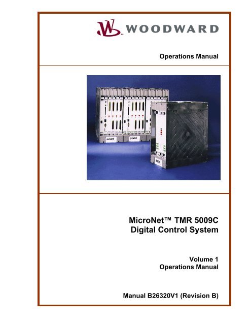
Operations Manual<br />
MicroNet <strong>TMR</strong> <strong>5009C</strong><br />
<strong>Digital</strong> <strong>Control</strong> <strong>System</strong><br />
Volume 1<br />
Operations Manual<br />
Manual B26320V1 (Revision B)
WARNING—DANGER OF DEATH OR PERSONAL INJURY<br />
WARNING—FOLLOW INSTRUCTIONS<br />
Read this entire manual and all other publications pertaining to the work to be performed<br />
before installing, operating, or servicing this equipment. Practice all plant and safety<br />
instructions and precautions. Failure to follow instructions can cause personal injury and/or<br />
property damage.<br />
WARNING—OUT-OF-DATE PUBLICATION<br />
This publication may have been revised or updated since this copy was produced. To verify<br />
that you have the latest revision, be sure to check the Woodward website:<br />
www.woodward.com/pubs/current.pdf<br />
The revision level is shown at the bottom of the front cover after the publication number. The<br />
latest version of most publications is available at:<br />
www.woodward.com/publications<br />
If your publication is not there, please contact your customer service representative to get<br />
the latest copy.<br />
WARNING—OVERSPEED PROTECTION<br />
The engine, turbine, or other type of prime mover should be equipped with an overspeed<br />
shutdown device to protect against runaway or damage to the prime mover with possible<br />
personal injury, loss of life, or property damage.<br />
The overspeed shutdown device must be totally independent of the prime mover control<br />
system. An overtemperature or overpressure shutdown device may also be needed for<br />
safety, as appropriate.<br />
WARNING—PROPER USE<br />
Any unauthorized modifications to or use of this equipment outside its specified<br />
mechanical, electrical, or other operating limits may cause personal injury and/or property<br />
damage, including damage to the equipment. Any such unauthorized modifications: (i)<br />
constitute "misuse" and/or "negligence" within the meaning of the product warranty<br />
thereby excluding warranty coverage for any resulting damage, and (ii) invalidate product<br />
certifications or listings.<br />
CAUTION—POSSIBLE DAMAGE TO EQUIPMENT OR PROPERTY<br />
CAUTION—BATTERY CHARGING<br />
To prevent damage to a control system that uses an alternator or battery-charging device, make<br />
sure the charging device is turned off before disconnecting the battery from the system.<br />
CAUTION—ELECTROSTATIC DISCHARGE<br />
Electronic controls contain static-sensitive parts. Observe the following precautions to<br />
prevent damage to these parts.<br />
• Discharge body static before handling the control (with power to the control turned off,<br />
contact a grounded surface and maintain contact while handling the control).<br />
• Avoid all plastic, vinyl, and Styrofoam (except antistatic versions) around printed circuit<br />
boards.<br />
• Do not touch the components or conductors on a printed circuit board with your hands<br />
or with conductive devices.<br />
IMPORTANT DEFINITIONS<br />
• A WARNING indicates a potentially hazardous situation which, if not avoided, could result in<br />
death or serious injury.<br />
• A CAUTION indicates a potentially hazardous situation which, if not avoided, could result in<br />
damage to equipment or property.<br />
• A NOTE provides other helpful information that does not fall under the warning or caution<br />
categories.<br />
Revisions—Text changes are indicated by a black line alongside the text.<br />
Woodward Governor Company reserves the right to update any portion of this publication at any time. Information<br />
provided by Woodward Governor Company is believed to be correct and reliable. However, no responsibility is<br />
assumed by Woodward Governor Company unless otherwise expressly undertaken.<br />
© Woodward 2005<br />
All Rights Reserved
Manual 26320V1 <strong>5009C</strong> Operations<br />
Contents<br />
ELECTROSTATIC DISCHARGE AWARENESS ................................................. IV<br />
CHAPTER 1. GENERAL INFORMATION........................................................... 1<br />
Introduction.............................................................................................................1<br />
<strong>Control</strong> <strong>System</strong> Installation Procedure...................................................................1<br />
CHAPTER 2. DESCRIPTION........................................................................... 3<br />
General...................................................................................................................3<br />
<strong>Control</strong> Fault Tolerance..........................................................................................3<br />
<strong>5009C</strong> <strong>Control</strong> <strong>System</strong> Inputs and Outputs..........................................................20<br />
Pilot Valve <strong>Control</strong> (Cascade Position Loop) .......................................................27<br />
PC Interface Program...........................................................................................29<br />
CHAPTER 3. CONTROL FUNCTIONALITY OVERVIEW .................................... 31<br />
<strong>Control</strong> Overview ..................................................................................................31<br />
Block Diagrams ....................................................................................................35<br />
CHAPTER 4. CONTROL FUNCTIONALITY ..................................................... 38<br />
Introduction...........................................................................................................38<br />
Valves Selection ...................................................................................................38<br />
Turbine Start Modes.............................................................................................42<br />
Valve Limiters .......................................................................................................48<br />
Turbine Start Routine ...........................................................................................49<br />
Speed <strong>Control</strong> Overview ......................................................................................53<br />
Speed PID Operational Modes.............................................................................54<br />
Valve Redundancy <strong>Control</strong>ler...............................................................................58<br />
Cascade <strong>Control</strong>...................................................................................................76<br />
Cascade Droop.....................................................................................................78<br />
Remote Cascade Set Point ..................................................................................78<br />
Seal GAS PID <strong>Control</strong> ..........................................................................................79<br />
Emergency Shutdown ..........................................................................................80<br />
<strong>Control</strong>led Shutdown ............................................................................................81<br />
Relays...................................................................................................................84<br />
CHAPTER 5. <strong>5009C</strong> CONTROL SYSTEM OPERATION .................................. 85<br />
Introduction...........................................................................................................85<br />
<strong>5009C</strong> <strong>System</strong> Power-up .....................................................................................85<br />
Valve / Actuator Calibration & Test ......................................................................86<br />
Turbine Start.........................................................................................................89<br />
General Field Tuning Guidelines..........................................................................99<br />
Speed, Casc, Decoupling, Seal Gas PID, and Ext/Adm Dynamics<br />
Adjustments........................................................................................................101<br />
Overspeed Test Function ...................................................................................103<br />
Operation Information.........................................................................................105<br />
CHAPTER 6. SERVICE OPTIONS ............................................................... 109<br />
Product Service Options.....................................................................................109<br />
Returning Equipment for Repair.........................................................................110<br />
Replacement Parts.............................................................................................111<br />
How to Contact Woodward.................................................................................111<br />
Engineering Services .........................................................................................112<br />
Technical Assistance..........................................................................................113<br />
DECLARATIONS....................................................................................... 114<br />
Woodward i
<strong>5009C</strong> Operations Manual 26320V1<br />
Illustrations and Tables<br />
Figure 2-1. <strong>System</strong> Module Diagram......................................................................4<br />
Figure 2-2. Double Exchange and Vote Structure .................................................5<br />
Figure 2-3. Fault Tolerant Analog Input..................................................................7<br />
Figure 2-4. Fault Tolerant Discrete Input................................................................8<br />
Figure 2-5. Fault Tolerant Analog Output.............................................................10<br />
Figure 2-6. Fault Tolerant Single Coil Actuator Output ........................................12<br />
Figure 2-7. Fault Tolerant Dual Coil Actuator Output...........................................13<br />
Figure 2-8. Fault Tolerant Discrete Output...........................................................16<br />
Figure 2-9. Fault Tolerant DDE Communication Ports.........................................17<br />
Figure 2-10. Fault Tolerant Modbus Communication Ports .................................18<br />
Figure 2-11. Fault Tolerant Modbus Communication Ports .................................19<br />
Figure 2-12. Interface/Communications Logic .....................................................20<br />
Figure 2-13. Proportional <strong>Control</strong>ler Diagram ......................................................22<br />
Figure 2-14. P <strong>Control</strong>ler Diagram .......................................................................23<br />
Figure 2-15. PI <strong>Control</strong>ler Diagram ......................................................................23<br />
Figure 2-16. PI Lag <strong>Control</strong>ler Diagram ...............................................................24<br />
Figure 2-17. PI Lead Lag <strong>Control</strong>ler Diagram ......................................................24<br />
Figure 2-18. Three-Wire Transducer....................................................................25<br />
Figure 2-19. Four-Wire Transducer......................................................................26<br />
Figure 2-20. Five-Wire Transducer ......................................................................26<br />
Figure 2-21. Six-Wire Transducer ........................................................................26<br />
Figure 2-22. Main Screen.....................................................................................30<br />
Figure 3-1. Typical Extraction and/or Admission Steam Turbine.........................31<br />
Figure 3-2. Split Range or Admission Type of Turbine Configuration..................32<br />
Figure 3-3. Extraction and/or Admission Steam Turbine .....................................33<br />
Figure 3-4. Overview of <strong>5009C</strong> <strong>Control</strong> <strong>System</strong> Functionality Notes...................35<br />
Figure 3-5. Single or Split-Range Turbine Configurations (Speed PID with<br />
Remote Set Point) ...........................................................................36<br />
Figure 3-6. Single or Split-Range Turbine Configurations ...................................36<br />
Figure 3-7. Extraction and/or Admission Turbine Configurations (coupled<br />
mode)...............................................................................................36<br />
Figure 3-8. Example of a Single Stage Turbine using Dual Loop Actuator and<br />
Remote Speed Set Point .................................................................37<br />
Figure 4-1. Typical Dual Loop Valve with Cylinder’s LVDT and Pilot’s LVDT as<br />
Represented in Woodward’s HMI....................................................40<br />
Figure 4-2. Dual <strong>Control</strong> Loop Valve With Cylinder’s LVDT and Pilot’s LVDT and<br />
Degraded Mode ...............................................................................41<br />
Figure 4-3. Manual Start Mode Example..............................................................43<br />
Figure 4-4. Semiautomatic Start Mode Example .................................................44<br />
Figure 4-5. Automatic Start Mode Example .........................................................45<br />
Figure 4-6. Automatic Start Sequence .................................................................50<br />
Figure 4-7. Speed <strong>Control</strong> Functional Diagram....................................................53<br />
Figure 4-8. Speed Relationships ..........................................................................57<br />
Figure 4-9. Typical Redundant I/H <strong>System</strong> with a Transfer Valve .......................59<br />
Figure 4-10. Typical Redundant I/P <strong>System</strong> with a Pressure Selecting Relay<br />
Valve ................................................................................................59<br />
Figure 4-11. Ext/Adm <strong>Control</strong> Diagram ................................................................64<br />
Figure 4-12. Coupled HP & LP Mode...................................................................74<br />
Figure 4-13. Decoupled Inlet or Exhaust Mode....................................................75<br />
Figure 4-14. Decoupled HP&LP Mode.................................................................76<br />
Figure 4-15. Cascade Functional Diagram ..........................................................77<br />
Figure 5-1. Proportional Gain Setting Effects.......................................................92<br />
Figure 5-2. Open Loop Proportional and Integral Response ...............................93<br />
ii Woodward
Manual 26320V1 <strong>5009C</strong> Operations<br />
Illustrations and Tables<br />
Figure 5-3. Closed Loop Proportional and Integral Response.............................94<br />
Figure 5-4. Integral Gain (Reset) Setting Responses ..........................................95<br />
Figure 5-5. Closed Loop Proportional and Derivative Action ...............................96<br />
Figure 5-6. Derivative Setting Effects...................................................................97<br />
Figure 5-7. Closed Loop Proportional, Integral and Derivative Action.................98<br />
Figure 5-8. Typical Response to Load Change..................................................100<br />
Table 2-1. Redundancy Manager Truth Table .......................................................8<br />
Table 6-1. Actuator combo Driver Limits..............................................................86<br />
Woodward iii
<strong>5009C</strong> Operations Manual 26320V1<br />
Electrostatic Discharge Awareness<br />
All electronic equipment is static-sensitive, some components more than others.<br />
To protect these components from static damage, you must take special<br />
precautions to minimize or eliminate electrostatic discharges.<br />
Follow these precautions when working with or near the control.<br />
1. Before doing maintenance on the electronic control, discharge the static<br />
electricity on your body to ground by touching and holding a grounded metal<br />
object (pipes, cabinets, equipment, etc.).<br />
2. Avoid the build-up of static electricity on your body by not wearing clothing<br />
made of synthetic materials. Wear cotton or cotton-blend materials as much<br />
as possible because these do not store static electric charges as much as<br />
synthetics.<br />
3. Keep plastic, vinyl, and Styrofoam materials (such as plastic or Styrofoam<br />
cups, cup holders, cigarette packages, cellophane wrappers, vinyl books or<br />
folders, plastic bottles, and plastic ash trays) away from the control, the<br />
modules, and the work area as much as possible.<br />
4. Do not remove the printed circuit board (PCB) from the control cabinet<br />
unless absolutely necessary. If you must remove the PCB from the control<br />
cabinet, follow these precautions:<br />
• Do not touch any part of the PCB except the edges.<br />
• Do not touch the electrical conductors, the connectors, or the<br />
components with conductive devices or with your hands.<br />
• When replacing a PCB, keep the new PCB in the plastic antistatic<br />
protective bag it comes in until you are ready to install it. Immediately<br />
after removing the old PCB from the control cabinet, place it in the<br />
antistatic protective bag.<br />
CAUTION—ELECTROSTATIC DISCHARGE<br />
To prevent damage to electronic components caused by improper handling,<br />
read and observe the precautions in Woodward manual 82715, Guide for<br />
Handling and Protection of Electronic <strong>Control</strong>s, Printed Circuit Boards, and<br />
Modules.<br />
iv Woodward
Manual 26320V1 <strong>5009C</strong> Operations<br />
Chapter 1.<br />
General Information<br />
Introduction<br />
The technical documentation for the <strong>5009C</strong> control system consists of the<br />
following volumes:<br />
Volume 1—provides information on system application, control functionality, fault<br />
tolerant logic, control logic, PID setting instructions, and system operation<br />
procedures.<br />
Volume 2—provides hardware descriptions, mechanical and electrical<br />
installation instructions, hardware specifications, hardware troubleshooting help,<br />
and basic repair procedures.<br />
Volume 3—provides installation procedures for the <strong>5009C</strong> control’s personal<br />
computer based interface software program (PCI), information on all PCI<br />
features and modes (Program, Service and Run), and a lists of the control’s<br />
Modbus ® * registers and DDE tag names.<br />
*—Modbus is a registered trademark of Modicon, Inc.<br />
Volume 4 (future)—provides details on installation and operation of the<br />
OpView operator control station, if provided with your system.<br />
<strong>Control</strong> <strong>System</strong> Installation Procedure<br />
1. Review all system manuals to gain an understanding of the control system.<br />
2. Create a site specific wiring diagram by referencing Volume 2’s wiring<br />
diagrams, then perform mechanical and electrical installation following<br />
Volume 2 instructions and the generated wiring diagram.<br />
3. Apply power to the <strong>5009C</strong> <strong>Control</strong> and reset all three CPU’s (refer to Volume<br />
2).<br />
4. Connect the provided RS-232 serial cable between the control’s CPU-C or<br />
SIOA J4 or SIO-B J3 serial port and a computer which will have the PCI<br />
program installed.<br />
5. Install the PCI programming software on a Windows ® 95, Windows 2000 or<br />
Windows NT ® based computer. Configure the system using the PCI’s menudriven<br />
programming screens (refer to Volume 3).<br />
6. Perform a full system checkout; clear all system trips and alarms; adjust<br />
linkages and stroke actuators.<br />
When ready to start the turbine, follow the operation instructions of Chapter 5 in<br />
this volume. During initial start-up, the dynamics of each PID controller will need<br />
to be adjusted (Chapter 5).<br />
Woodward 1
<strong>5009C</strong> Operations Manual 26320V1<br />
This volume provides control system description, and operation instructions for<br />
the Woodward MicroNet <strong>TMR</strong> <strong>5009C</strong> <strong>Control</strong> <strong>System</strong>. It includes:<br />
• General description of the control system<br />
• Detailed functionality descriptions including I/O handling<br />
• <strong>Control</strong> system operation<br />
• Information on optional equipment<br />
• Detailed functionality description of start up procedures<br />
• Detailed information on alarm and trip messages<br />
• Detailed information on Modbus parameters<br />
This manual applies to all <strong>5009C</strong> <strong>Control</strong> <strong>System</strong>s but does not include<br />
information that is unique to your system. The <strong>5009C</strong> <strong>Control</strong> <strong>System</strong> can be<br />
provided in a number of hardware configurations: with different power supply<br />
configurations, with or without a cabinet, with or without an OpView, or with or<br />
without a Rolling Restart Station. Because this manual addresses all<br />
configurations, many of the system software and hardware descriptions may not<br />
apply to your particular <strong>5009C</strong> <strong>System</strong>.<br />
When an optional cabinet is included with the <strong>5009C</strong> <strong>Control</strong> <strong>System</strong> package,<br />
all equipment is pre-wired and the control is shipped fully assembled within the<br />
cabinet. If a cabinet is not included with the system, each component is<br />
packaged separately. After a control system is received each item must be<br />
located and installed via this manual’s instructions.<br />
This manual does not contain instructions for the operation of the complete<br />
turbine system. For turbine or plant operating instructions, contact the plantequipment<br />
manufacturer.<br />
2 Woodward
Manual 26320V1 <strong>5009C</strong> Operations<br />
Chapter 2.<br />
Description<br />
General<br />
The <strong>5009C</strong> Fault-Tolerant <strong>Control</strong> <strong>System</strong> is designed to control single valve,<br />
split- range valve, single controlled-extraction, single controlled-admission, or<br />
single controlled-extraction/admission steam turbines. The <strong>5009C</strong> <strong>Control</strong><br />
<strong>System</strong> is field programmable which allows a single design to be used in many<br />
different control applications and reduces both cost and delivery time. It uses<br />
Windows-based computer program (PCI) to allow a user to configure the control,<br />
perform on-line program changes, perform on-line hardware tests, and<br />
alternatively operate the turbine from HMI. This control can be used as a standalone<br />
unit or in conjunction with a plant’s Distributed <strong>Control</strong> <strong>System</strong> (DCS).<br />
<strong>Control</strong> Fault Tolerance<br />
The basis of this control’s fault tolerance architecture is to detect control related<br />
faults, annunciate these faults, and allow on-line service/replacement of modules<br />
and/or transducers to correct these faults.<br />
This control’s architecture allows it to operate with any single point of failure,<br />
without shutting down the turbine. A CPU fault tolerance logic of 3-2-0 allows the<br />
control to function normally with any CPU module failed or removed. An analog<br />
I/O fault tolerance logic of 3-2-1-0 allows the control to function normally with any<br />
one or two analog modules failed or removed. A discrete I/O fault tolerance logic<br />
of 3-2-0 allows the control to function normally with any one discrete module<br />
failed or removed. A power supply fault tolerance logic of 2-1-0 allows the control<br />
to function normally with any one power supply failed or removed.<br />
Three isolated kernel sections (A, B & C) each house a Kernel Power Supply<br />
module, CPU module, Analog I/O module, and a Discrete I/O module. Kernels A<br />
and B each house a Serial Input/Output (SIO) module (see Figure 2-1). A single<br />
motherboard supplies nine electrically isolated data paths. Each CPU has a data<br />
path to its VME modules and two separate data paths, one to each of the other<br />
CPU modules. There is a total of six paths between CPUs allowing for<br />
redundancy and error checking.<br />
All control inputs and outputs are Triple Modular Redundant (<strong>TMR</strong>) with the<br />
exception of the actuator cards (dual redundant); meaning that each individual<br />
analog and speed input is monitored by all three <strong>5009C</strong> <strong>Control</strong> <strong>System</strong> kernels,<br />
then voted upon to insure that the correct input value is used for control. Each<br />
input is split at one of the control’s field termination module, and routed to the<br />
three kernels (A,B,C) via separate I/O cables; this allows on-line module<br />
replacement. Each control output signal is the sum of the three kernels outputs.<br />
Because the control monitors the health of each kernel’s output signal, it can<br />
detect, alarm, and react to any system output fault.<br />
The <strong>5009C</strong> <strong>Control</strong> <strong>System</strong> allows redundancy to be extended beyond the<br />
control, by allowing multiple transducers to be used for any critical control<br />
parameter. Optionally the control can be configured to accept up to three speed<br />
sensor inputs, and three analog input signals (from separate transducers) for any<br />
single critical control parameter.<br />
Woodward 3
<strong>5009C</strong> Operations Manual 26320V1<br />
A fourth speed input can be configured for null speed detection. If used, the<br />
control will use this signal during start-up to control the engine at a very low<br />
speed.<br />
Figure 2-1. <strong>System</strong> Module Diagram<br />
Each CPU module runs the identical software application as the other two. All<br />
inputs from each kernel are distributed to the other two kernels. Each CPU then<br />
compares the value it read, with the value the other two CPUs read, before<br />
outputting a signal to the application software. Depending on the configuration, a<br />
total of nine values for the same input parameter could be used in the voting<br />
logic to provide the best signal to the application software. Even if a data value<br />
has been corrupted along any one of the data paths shown in Figure 2-2, all<br />
CPUs use the same correct data for their application calculations. All CPUs use<br />
the same voted input signals in the same application calculations to generate the<br />
same outputs.<br />
All output values are exchanged between kernels, the results are voted and the<br />
appropriate value is output from each kernel. Since the system can handle<br />
significant single errors, even multiple errors may not shutdown a kernel section.<br />
In the event of consistent errors from one of the kernel section, an alarm will be<br />
annunciated and that particular kernel will be shut down. Figure 2-2 shows the<br />
input to output structure of the MicroNet <strong>TMR</strong>.<br />
The <strong>5009C</strong> <strong>Control</strong> <strong>System</strong>’s redundancy architecture allows all control modules<br />
to be replaced one at a time while the turbine is on-line and operating at full<br />
power (sometimes referred to a Hot Replacement). This type of architecture also<br />
allows it to perform all control system functions while only utilizing the following<br />
modules:<br />
• Main Power Supply module (2 typical)<br />
• 2 Kernel Power Supply modules (3 typical)<br />
• 2 CPU modules (3 typical)<br />
• 2 Discrete I/O modules (3 typical)<br />
• 1 Analog I/O module (3 typical)<br />
• 1 Actuator module (2 typical)<br />
• 1 Serial I/O module (2 typical)<br />
4 Woodward
Manual 26320V1 <strong>5009C</strong> Operations<br />
Speed Inputs<br />
Figure 2-2. Double Exchange and Vote Structure<br />
The control can accept one, two, or three speed inputs. Each speed input is<br />
monitored by all three kernels. With nine possible speed signals from which to<br />
control with, the control can withstand multiple speed input failures with no loss<br />
of control functionality. Only one of the possible nine inputs is required for speed<br />
control.<br />
All speed inputs are connected to the control, via analog termination modules<br />
(ATMs). An input’s termination module is used to terminate customer control<br />
wiring and distribute each input signal to all three kernels. After the control’s<br />
kernels double exchange their input values, and vote out any erroneous values,<br />
the Application Software Redundancy Manager then compares each kernel’s<br />
voted result to select a value to be used within the application logic. Figure 2-3 is<br />
a graphical view of a control input’s architecture. Table 2-1 displays the<br />
redundancy manager’s input selection logic, for each possible input condition.<br />
A speed input signal is determined to be faulty and is taken out of the input<br />
voting logic when it is below its “Speed Failure Level” setting. This failure level<br />
setting is common to all inputs and can be adjusted via the PCI program’s<br />
Service mode. Refer to Volume 3 for all PCI program procedures.<br />
Woodward 5
<strong>5009C</strong> Operations Manual 26320V1<br />
An input deviation alarm is also used to annunciate if any of the three possible<br />
speed input channels is sensing a value that is different then the voted-good<br />
value used by the application. If an input channel’s sensed value deviates from<br />
the voted-good signal value, by a greater margin than the speed control’s “Max<br />
Deviation” setting, an input channel alarm will be issued. This type of<br />
annunciation can be used to indicate when an input channel, or magnetic pickup<br />
unit is intermittently failing high or low. Max Deviation input settings are tunable<br />
via the PCI program’s Service mode, and are defaulted to 1% (deviation range =<br />
.01 to 20%) of the “Overspeed Limit” setting. If a deviation alarm condition<br />
occurs, the alarmed input is not removed from the control’s voting logic and still<br />
can be used to control with, in case all other channels fail.<br />
The voting logic when more than one speed input (MPU or proximity probe) is<br />
used is as follows:<br />
• With 3 good sensors, use the median value<br />
• With 2 good sensors, use the higher value<br />
• With 1 good sensor, use the good sensor’s value<br />
Zero Speed Inputs<br />
The Speed input #4 channel is separated from the others. Its range can be set<br />
for a low speed detection. During start-up, this reading will be used by the<br />
control, up to the maximum range of this sensor.<br />
Relay output configured for speed level will use this channel to increase the<br />
accuracy of the reading for very low speed.<br />
The usage of this channel is recommended, while a turning gear must not start<br />
while engine is still rotating.<br />
Special protection feature have been added for this channel, in conjunction with<br />
relay output configured for null speed detection.<br />
The signal from channel #4 , is compared with the other channels and an alarm<br />
will be initiated if discrepancy is notice. Null speed relay won’t energize until null<br />
speed detection function is re-armed, via a dedicated input (Modbus/hardware).<br />
Normal RESET won’t re-arm this function.<br />
When zero speed is reached, a delay can be applied before the “null speed”<br />
relay energize.<br />
To increase the zero speed detection safety, a contact input called “ zero speed<br />
permissive” can be configured. If configured, the null speed relay will energize<br />
only if this contact is closed.<br />
The zero speed probe is always used in the control. Should no extra protections<br />
be needed to detect zero speed, a relay can be set as a level switch on speed<br />
with a very low speed level.<br />
Analog Inputs<br />
The control can accept one, two, or three transducer inputs for all critical<br />
parameters (ext/adm, decoupling, casc inputs). Only one input signal is accepted<br />
for non-critical functions (remote set point inputs). Each analog input can<br />
withstand up to two failures with no loss of control functionality. If any two of an<br />
analog input’s three “legs” are failed, the control uses the third healthy leg’s<br />
sensed input signal from which to control with.<br />
6 Woodward
Manual 26320V1 <strong>5009C</strong> Operations<br />
All analog inputs are connected to the control, via analog termination modules<br />
(ATMs). An input’s termination module is used to terminate customer control<br />
wiring and distribute each input signal to all three kernels. After the control’s<br />
kernels double exchange their input values, and vote out any erroneous values,<br />
the Application Software Redundancy Manager then compares each kernel’s<br />
voted result to select a value to be used within the application logic. Figure 2-3 is<br />
a graphical view of a control’s input architecture. Table 2-1 displays the<br />
redundancy manager’s input selection logic, for each possible input condition.<br />
Optionally, each leg of an input channel can be tested and its calibration verified<br />
through the PCI program’s Service mode, by individually removing the other two<br />
input legs. Refer to Volume 3 for all PCI program mode procedures.<br />
An analog input signal is determined to be faulty when it is below 2 mA , or<br />
above 22 mA. and 22 mA respectively. If an input is determined to be failed, that<br />
input is removed from the control’s voting logic.<br />
Input deviation alarms are used to annunciate if any of the input channels or<br />
input legs are sensing a value that is different then the voted-good value used by<br />
the application. If an input channel’s sensed value deviates from the voted-good<br />
value, by a greater margin than its “Max Deviation” setting, an input channel<br />
alarm will be issued. This type of annunciation can be used to indicate when an<br />
input channel, or system transducer is going out of calibration. Max Deviation<br />
settings are tunable via the PCI program’s Service mode, and are defaulted to<br />
1% (deviation range = .1 to 10%) of the configured input range. If a deviation<br />
alarm condition occurs the alarmed input is not removed from the control’s voting<br />
logic, and still can be used to control with, in case all other channels fail.<br />
TRANSDUCER #1<br />
TRANSDUCER #2<br />
TRANSDUCER #3<br />
ATM<br />
ATM<br />
ATM<br />
MOD<br />
A<br />
MOD<br />
B<br />
MOD<br />
C<br />
MOD<br />
A<br />
MOD<br />
B<br />
MOD<br />
C<br />
MOD<br />
A<br />
MOD<br />
B<br />
MOD<br />
C<br />
INPUT 1<br />
VOTING<br />
INPUT 2<br />
VOTING<br />
INPUT 3<br />
VOTING<br />
Figure 2-3. Fault Tolerant Analog Input<br />
INPUT<br />
VOTING<br />
855−662<br />
02−12−31<br />
CONTROL<br />
LOGIC<br />
Woodward 7
<strong>5009C</strong> Operations Manual 26320V1<br />
Discrete Inputs<br />
Table 2-1. Redundancy Manager Truth Table<br />
Each discrete input can withstand up to two failures with no loss of control<br />
functionality. If any two of a discrete input’s three “legs” fail, the control uses the<br />
third healthy leg’s sensed input signal from which to control with.<br />
All discrete inputs are connected to the control via discrete termination modules<br />
(DTMs). A DTM is used to terminate customer control wiring and distribute each<br />
input signal to all three kernels. After the control’s kernels double exchange their<br />
input values and vote out any erroneous inputs, the Application Software<br />
Redundancy Manager then compares each kernel’s voted result to select a value<br />
to be used within the application logic. Figure 2-4 is a graphical view of the<br />
control’s discrete input architecture.<br />
Figure 2-4. Fault Tolerant Discrete Input<br />
A discrete input signal is determined to be faulty when it is determined to be<br />
different then the voted-good value used by the application. If an input is<br />
determined to be faulty, the input is removed from the control’s voting logic and<br />
an input channel alarm is issued. Once the input fault is corrected the alarm<br />
condition can be reset by issuing a control “Reset” command.<br />
8 Woodward
Manual 26320V1 <strong>5009C</strong> Operations<br />
Readouts (Analog Outputs)<br />
Each control readout can withstand up to two failures with no loss of output<br />
functionality. Any leg of an output channel can drive a readout’s full 4–20 mA<br />
current signal. After each CPU generates an analog output signal, the signals are<br />
exchanged between CPUs, voted on, and sent to the Redundancy Manager for<br />
output. The Redundancy Manager divides the output signal based on the number<br />
of known good output channels and distributes each portion of the signal to the<br />
respective output channel.<br />
Precision resistors are used in each channel’s readback circuitry to measure and<br />
verify the health of each output “leg”. If a fault condition is detected, the faulty<br />
output leg is disabled, and the Redundancy Manager redistributes the output<br />
signal to the remaining legs. In a case where two failures are experienced at the<br />
same time within different legs, the single good channel (leg) will drive the entire<br />
output. Figure 2-5 shows a Fault Tolerant Analog Output’s architecture. The<br />
Analog Termination Module (ATM) combines each analog output signal from all<br />
three kernels into one signal at the ATM’s terminal blocks.<br />
An output is considered failed, and an alarm issued, if a channel’s combined<br />
output or any leg of the output measures a difference of more than 10% from the<br />
output demand. Optionally, each leg of a readout channel can be tested and its<br />
calibration verified through the PCI program’s Service mode, by individually<br />
removing the other two output legs. Refer to Volume 3 for all PCI program<br />
functionality.<br />
With this output architecture, any single output driver failure results in the output<br />
signal only stepping to 66.66% of its original value. The time between when a<br />
failure is sensed and when the control corrects for it by redistributing current<br />
through the other drivers can be as long as 50 milliseconds.<br />
Upon the correction of an output failure, and a “<strong>Control</strong> Reset” command, each<br />
failed output performs a continuity check though the its external load before<br />
current is again redistributed evenly between all output drivers. This continuity<br />
check entails, the failed driver to output a small amount of current through its<br />
output load, and compare that value with what is readback. The time between<br />
when a continuity check is performed and when the control redistributes current<br />
through the all drivers can be as long as 50 milliseconds.<br />
Woodward 9
<strong>5009C</strong> Operations Manual 26320V1<br />
Figure 2-5. Fault Tolerant Analog Output<br />
Actuator Outputs from Combo card<br />
Each actuator output can withstand up to two failures with no loss of output<br />
functionality. Any leg of an output channel can drive an output’s full current signal<br />
(4–20 mA or 20–160 mA). After each CPU generates an actuator output signal,<br />
the signals are exchanged between CPUs, voted on, and sent to the<br />
Redundancy Manager for output. The Redundancy Manager divides the output<br />
signal based on the number of known good output channels and distributes each<br />
portion of the signal to the respective output channel.<br />
Precision resistors are used in each channel’s readback circuitry to measure and<br />
verify the health of each output “leg”. If a fault condition is detected, the faulty<br />
output leg is disabled, and the Redundancy Manager redistributes the output<br />
signal to the remaining legs. In a case where two failures are experienced at the<br />
same time within different legs, the lone good channel (leg) will drive the entire<br />
output. Figures 2-6 and 2-7 show a Fault Tolerant Actuator Output’s architecture.<br />
The Analog Termination Module (ATM) combines each actuator output signal<br />
from all three kernels into one signal at the ATM’s terminal blocks.<br />
10 Woodward
Manual 26320V1 <strong>5009C</strong> Operations<br />
An output is considered failed, and an alarm issued, if a channel’s combined<br />
output or any leg of the output measures a difference of more than 10% from the<br />
output demand. Optionally, each leg of a readout channel can be tested and its<br />
calibration verified through the PCI program’s Service mode, by individually<br />
removing the other two output legs. Refer to Volume 3 for all PCI program<br />
functionality.<br />
Actuator outputs, or HP and LP valve outputs, are treated the same way as the<br />
other analog outputs, with the exception of a an added precision resistor in the<br />
actuator output’s return path. This resistor is used to measure and detect ground<br />
loops and coil shortages that are possible when interfacing to an actuator. If a<br />
single coil actuator is being driven, the dual coil terminal blocks are jumpered<br />
(wired) to the single coil terminal blocks and the redundancy manager shares the<br />
current equally between all three kernels. In the event of a fault, the Redundancy<br />
Manager will redistribute the load.<br />
If the actuator connected to is a dual coil actuator, the Redundancy Manager<br />
shares half the current evenly between Kernels A & B outputs, and the other half<br />
comes from the Kernel C output. In the event of a fault, the Redundancy<br />
Manager redistributes load current.<br />
With this output architecture, any single output driver failure results in the output<br />
signal only stepping to 66.66% of its original value (possibly 50% for dual coil<br />
applications). The time between when a failure is sensed and when the control<br />
corrects for it by redistributing current through the other drivers can be as long as<br />
50 milliseconds.<br />
Upon the correction of an output failure, and a “<strong>Control</strong> Reset” command, each<br />
failed output performs a continuity check though the actuator before current is<br />
again redistributed evenly between all output drivers. This continuity check<br />
entails, the failed driver to output a small amount of current through its output<br />
load, and compare that value with what is readback. The time between when a<br />
continuity check is performed and when the control redistributes current through<br />
the all drivers can be as long as 50 milliseconds.<br />
Woodward 11
<strong>5009C</strong> Operations Manual 26320V1<br />
Figure 2-6. Fault Tolerant Single Coil Actuator Output<br />
12 Woodward
Manual 26320V1 <strong>5009C</strong> Operations<br />
Figure 2-7. Fault Tolerant Dual Coil Actuator Output<br />
Actuator card Outputs Setup<br />
Because the <strong>5009C</strong> offers so many options for actuation control, read this<br />
section carefully in order to choose the correct equipment and settings.<br />
Though each actuator acts independently according to the <strong>5009C</strong> control logic,<br />
each of the two actuator pairs’ output configuration and tuning consists of the<br />
same parameters, and as such, actuator setup will be discussed here<br />
generically. This does not mean that all actuators must be the same; they may<br />
be applied and setup differently as needed.<br />
Woodward 13
<strong>5009C</strong> Operations Manual 26320V1<br />
WARNING—SHUT OFF STEAM<br />
Before calibrating or testing, the unit must be tripped and the steam supply<br />
removed. This is to ensure that opening the control valve(s) will not allow<br />
steam into the turbine. Overspeeding the turbine may cause damage to<br />
turbine and can cause severe injury or death to personnel. STEAM TO THE<br />
TURBINE MUST BE SHUT OFF BY OTHER MEANS DURING THIS PROCESS.<br />
The <strong>5009C</strong> can be configured to utilize Woodward 2 Channel Actuator Modules<br />
and FTMs to drive a current source to the actuators. Each Valve is assigned two<br />
actuator drivers, whether wired in parallel to one actuator coil or separately to<br />
each coil in a dual coil actuator. If wired in parallel to one coil, no diode or<br />
suppression devices should be necessary in the circuit.<br />
For analysis purposes, position demand, position feedback, and the output of 2channel<br />
actuator controller modules are in %. To obtain the actuator current,<br />
multiply the output of the controller by:<br />
Proportional Actuator: (MA_AT_100 - MA_AT_0)(MA) / 100%<br />
Integrating Actuator (all others): (MAX_I - MIN_I)(MA) / 200%<br />
Setup information is identical for each coil in a redundant set and is entered only<br />
once for each redundant pair. Settings are first entered on the Configuration -><br />
Valve Setup screen of the PCI Configuration Tool. On this page of the<br />
Configuration Tool the Actuator <strong>Control</strong>ler Type, Actuator Direction, Position<br />
Feedback Transducer Type and Excitation Amplitude must be selected.<br />
Command Trim Enable may be deselected if the Actuator <strong>Control</strong>ler Type is<br />
Proportional.<br />
Proportional gain, integral gain, lead time constant, lag time constant and dither<br />
current amplitude are configured in PCI software only.<br />
The following descriptions will discuss choosing the correct settings for each of<br />
the following configuration parameters:<br />
Actuator <strong>Control</strong>ler Type<br />
Command Trim Enable<br />
Actuator Direction<br />
Position Transducer Type<br />
Excitation Amplitude<br />
And the following tuning parameters:<br />
Proportional Gain = KP<br />
Integral Gain = KI<br />
Lead Time Constant = T_LEAD<br />
Lag Time Constant = LAG_RATIO<br />
Dither Current Amplitude<br />
Enable Open Circuit Alarm<br />
Feedback Fail High / Low Select<br />
Configuration Parameters can be adjusted at any time but will not take affect until<br />
the <strong>5009C</strong> is reset. Tuning parameters may be adjusted at any time and will<br />
instantaneously update operation with the new values.<br />
14 Woodward
Manual 26320V1 <strong>5009C</strong> Operations<br />
Relay Outputs<br />
Twelve fault tolerant relay outputs are provided with this control. With this<br />
control’s architecture, a six relay configuration is used to form each fault tolerant<br />
relay output. When a relay output is closed, the contacts of all six relays are<br />
closed. Because of the series-parallel configuration that the relays are in, the<br />
failure of any individual relay will not cause the output to be open. This series-<br />
parallel configuration also allows any single relay of the six relay configuration to<br />
be removed and replaced “on-line” with no affect on the state of the fault tolerant<br />
relay output.<br />
When a relay output is open, the contacts of all six relays are open. Because of<br />
the series-parallel configuration that the relays are in, the failure or removal of<br />
any one relay will not cause the output to be closed. The relay output would<br />
continue to be open.<br />
Since this control’s fault tolerant architecture can tolerate a single fault, it is<br />
possible for this fault to go undetected. This is called a latent fault. If a second<br />
fault occurs while a latent fault exists, the state of the fault tolerant relay output<br />
may be affected, possibly resulting in a shutdown condition. This is why it is<br />
important to detect and annunciate latent faults in a fault tolerant system.<br />
Latent fault detection is provided with this control to detect any relay related<br />
failure without affecting the state of the overall relay output. Each individual relay<br />
output can be configured to use or not use latent fault detection. A latent fault<br />
detection test is performed periodically or on command through the PCI. The<br />
period of time between tests can be set from 1 to 3000 hours.<br />
A relay output is tested by cycling the output’s individual relays closed then open<br />
(or vice-versa depending on the output state), to ensure that they are in the<br />
correct state, and that they can change state. Position readback circuitry allows<br />
the state of each relay contact to be detected. Any failures are annunciated, and<br />
further testing is disabled without affecting the state of the relay output contact or<br />
control operation.<br />
Each fault tolerant relay configuration consists of 6 relays, driven by two discrete<br />
outputs from each kernel (as shown in Figure 2-8). The relays are configured in<br />
three legs of two relays each. Customer circuit power is connected to one side of<br />
the resulting configuration, and customer load to the other side. Field selectable<br />
jumpers, located on system FTMs, are provided to allow each output’s latent fault<br />
detection logic to be compatible with the circuit being interfaced to. Latent fault<br />
detection is used to monitor the actual contact positions of each of the six relays,<br />
and to momentarily change states of each relay one at a time. This verifies each<br />
relay’s “normally open” or “normally closed” contacts.<br />
Woodward 15
<strong>5009C</strong> Operations Manual 26320V1<br />
Figure 2-8. Fault Tolerant Discrete Output<br />
Latent fault detection (LFD) is not usable with all applications or circuits. The<br />
control’s LFD logic can only work with circuits using voltages between 18- 32Vdc,<br />
100-150Vdc, or 88-132Vac. For latent fault detection to work, a small leakage<br />
current is passed through the circuit’s load. Depending on the size of the load,<br />
the leakage current may be enough to cause a load to be on or active, when a<br />
relay contact is open. In this case, the individual relay’s latent fault detection logic<br />
may be disabled, eliminating the leakage current, or a shunt resister can be used<br />
across the load to reduce the leakage current. Refer to Volume 2 of this manual<br />
to determine if Latent Fault Detection can be used with a circuit.<br />
DDE Communication Ports<br />
The CPU-C RS-232 port is dedicated for the use with the control’s PCI program<br />
(communicating via DDE). Serial Input/Output (SIO) modules are provided in the<br />
A and B kernel sections to increase communication redundancy or the number of<br />
available communications port. SIO-A port 4 (RS-232/422/485) and SIO-B port 3<br />
(RS-232/422/485) can be configured to communicate with the PCI program<br />
(DDE).<br />
CPU-B (RS-232) can also be configured to revert from its normal<br />
communications function to PCI (DDE) communications in the event that the<br />
kernel-C CPU fails. Once the Kernel-C CPU is restored and reset, the CPU-B<br />
port will revert back to its original functionality (Modbus or printer).<br />
16 Woodward
Manual 26320V1 <strong>5009C</strong> Operations<br />
Figure 2-9. Fault Tolerant DDE Communication Ports<br />
All communication input values and commands from each port are double<br />
exchanged between all three CPUs and voted on to vote out any erroneous input<br />
values or commands before the application software is given the value or<br />
command. All communication output values or indications are also double<br />
exchanged between all three CPUs and voted on to vote out any erroneous<br />
output values or indications before the value or indication is output to the<br />
communications port.<br />
Modbus Communication Ports<br />
The CPU-A and CPU-B RS-232 ports can be configured for Modbus<br />
Communications with a distributed control system (DCS) or other serial operator<br />
control panel.<br />
Serial Input/Output (SIO) module are provided in the A and B kernel sections to<br />
increase communication reliability, redundancy or the number of available<br />
communication ports. When an SIO is installed, it will replace the CPU port for<br />
Modbus communication. SIO-A port 3 (RS-232/422/485) will replace CPU-A port,<br />
and SIO-B port 4 (RS-232/422/485) will replace CPU-B (if configured for<br />
Modbus). SIO-A port 4 (RS-232/422/485) and SIO-B port 3 (RS-232/422/485)<br />
can be configure as redundant Modbus lines.<br />
Woodward 17
<strong>5009C</strong> Operations Manual 26320V1<br />
All communication input values and commands from each port are double<br />
exchanged between all three CPUs and voted on to vote out any erroneous input<br />
values or commands before the application software is given the value or<br />
command. All communication output values or indications are also double<br />
exchanged between all three CPUs and voted on to vote out any erroneous<br />
output values or indications before the value or indication is output to the<br />
communications port.<br />
Figure 2-10. Fault Tolerant Modbus Communication Ports<br />
Printer Communication Ports<br />
The CPU-B RS-232 port can be configured to interface with a serial line-printer to<br />
provide a hard-copy of any Major alarm or trip condition. Serial Input/Output<br />
(SIO) modules are provided in the A and B kernel sections to increase<br />
communication redundancy or the number of available communication ports. All<br />
SIO module ports are dedicated to a communication protocol or function. Each<br />
SIO module’s port # 1 is dedicated to function as a Major Alarm/Trip printer port.<br />
With two SIO modules in one <strong>5009C</strong> <strong>Control</strong>, up to three ports are available for<br />
Major Alarm/Trip printer communications.<br />
All communication output indications are also double exchanged between all<br />
three CPUs and voted on to vote out any erroneous output indications before the<br />
indication is output to the communications port.<br />
18 Woodward
Manual 26320V1 <strong>5009C</strong> Operations<br />
Figure 2-11. Fault Tolerant Modbus Communication Ports<br />
Interface/ Communications Logic<br />
Internal control logic referred to as LOCAL/REMOTE functionality, permits a<br />
combination of Modbus ports and or contact input commands to be temporarily<br />
disabled. This logic allows a user at one interface panel to lockout commands<br />
from other turbine/control interface panels. For safety reasons, the PCI<br />
(engineering workstation) ports are not affected by this logic.<br />
The selection of the “Local” interface mode disables all ports so configured. The<br />
selection of the “Remote” interface mode enables all interfaces. Modbus port 1,<br />
Modbus port 2, and the control’s contact input commands, each have individual<br />
Local mode settings to allow a customer to configure the interface lockout<br />
functionality desired. Optionally the control can be configured such that all<br />
interfaces are enabled at all times. Refer to Figure 2-12 for a graphical view of<br />
the control’s interface logic.<br />
Woodward 19
<strong>5009C</strong> Operations Manual 26320V1<br />
Figure 2-12. Interface/Communications Logic<br />
<strong>5009C</strong> <strong>Control</strong> <strong>System</strong> Inputs and Outputs<br />
Speed Sensor Inputs<br />
Available Speed Sensor Inputs: 3+1(null speed)<br />
Of the 3 available fault-tolerant speed sensor inputs, one input is required for<br />
operation and the 3 additional inputs are optional for system redundancy. Each<br />
speed input can interface with a passive speed probe (magnetic pickup unit -<br />
MPU) or an active speed probe (proximity). Refer to Volume 2 for input wiring<br />
and specifications.<br />
Analog Inputs<br />
Available Analog Inputs: 8<br />
Any analog input can be configured to perform any of the listed control input<br />
functions. This control only accepts 4–20 mA signals. These 4–20 mA inputs,<br />
however, can be configured to interface with loop-powered or self-powered<br />
transducers, through ATM input wiring. Refer to Volume #3 for a complete list of<br />
all possible analog input functions.<br />
20 Woodward
Manual 26320V1 <strong>5009C</strong> Operations<br />
Discrete Inputs<br />
Available Discrete Inputs: 24<br />
Of the 24 total discrete inputs, 7 are dedicated and 17 are configurable. The<br />
seven dedicated inputs are Emergency Trip#1, Emergency Trip#2, <strong>Control</strong><br />
Reset, Start Command, Speed Set Point Raise, Speed Set Point Lower, and<br />
Halt/Continue Start Sequence. Only one discrete input may be programmed for<br />
any one listed option; more than one will result in a configuration error. Refer to<br />
Volume #3 for a complete list of all possible discrete input functions.<br />
First out—By configuring multiple discrete inputs to function as external trips or<br />
alarms, the control can function as a “First-Out” monitor to assist in system<br />
troubleshooting. The other discrete inputs are not time stamped.<br />
Readouts—Analog Outputs<br />
Available Readouts: 4<br />
Any readout can be configured to perform any of the listed control readout<br />
functions. These readouts only drive an output current of 4–20 mA. There are no<br />
configuration limitations on the analog output programming. For example, all four<br />
outputs could be configured to function as a speed readouts, if desired. These<br />
outputs are driven at a slower rate than the actuator outputs, and are not<br />
intended to function as actuator drivers. Refer to Volume #3 for a complete list of<br />
all possible readout functions.<br />
Actuator Combo Outputs<br />
Available Actuator Outputs: 2<br />
Each actuator output can be configured to output current ranges of 4–20 mA or<br />
20–160 mA, and to interface with single or dual coil actuators. When a single-coil<br />
actuator is used, all three kernel output drivers are tied together and share<br />
current proportionally. When a dual-coil actuator is used all three also share<br />
output current, however, kernels A & B are tied directly together through the ATM<br />
to the coil #1 output and kernel C provides the coil #2 output.<br />
The usage of the actuator output is configurable in PCI software.<br />
The options available are:<br />
• HP valve<br />
• HP2 valve (split or redundant)<br />
• LP valve (if extraction turbine only)<br />
• LP2 valve (split, Extraction & Admission with separated valves)<br />
If an actuator combo output is not used to control a valve, then it can be<br />
configured as a simple 4–20 mA Analog readout, with the same option as for<br />
normal analog readouts.<br />
Woodward 21
<strong>5009C</strong> Operations Manual 26320V1<br />
Actuator Cards-<strong>Control</strong>ler Type<br />
Proportional actuators will simply scale the demand (0-100%) to the actuator<br />
module to a 0% milliamp and 100% milliamp. If no feedback is used, then<br />
command trim enable must not be used and positioning will be open loop based<br />
on the 0% and 100% parameters set during actuator calibration. If feedback is<br />
used with command trim enable, then positioning will be based on the 0% and<br />
100% milliamp values but position will also be adjusted to trim out any error<br />
between the output and feedback. Proportional actuators will only use the<br />
actuator mA at 0% and actuator mA at 100% parameters during calibration.<br />
Integrating actuators utilize a null current and minimum current and maximum current<br />
settings to position the valve based on a closed loop with position feedback. 0%<br />
demand does not correspond to minimum current nor does 100% demand correspond<br />
to maximum current. Changing the demand to the module will create an error between<br />
demand and feedback and the module will accordingly increase or decrease current to<br />
get a different position feedback and correct the error. In a forward acting controller,<br />
maintaining constant demand will output the null current and maintain the actuator<br />
position. Increasing demand will cause the module to increase current above the null<br />
and will increase actuator position. Decreasing demand will cause the module to<br />
decrease the current below the null setting and will decrease actuator position. The<br />
amount by which current increases above, or decreases below, the null current results<br />
from the magnitude of the demand – position error and along with the controller<br />
settings affects how fast the actuator reacts. Integrating actuators will only use the<br />
minimum output current, maximum output current and null current parameters during<br />
calibration.<br />
The type chosen in the configuration tool (Figure 2-13) will be one of the<br />
following:<br />
1 - Proportional (proportional)<br />
2 - P (integrating)<br />
3 - PI (integrating)<br />
4 - PI Lag (integrating)<br />
5 - PI Lead (integrating)<br />
Following are further descriptions of each type.<br />
Proportional Actuator (Proportional or PROP):<br />
Figure 2-13. Proportional <strong>Control</strong>ler Diagram<br />
CTRL_TYPE = PROP<br />
KP = N/A<br />
KI = integral time constant<br />
T_LEAD = N/A<br />
LAG_RATIO = lag time constant<br />
22 Woodward
Manual 26320V1 <strong>5009C</strong> Operations<br />
The proportional actuator controller uses a "command trim" scheme to reduce<br />
steady-state position errors. When the CT_ENBL input is false, the output equals<br />
the input. When CT_ENBL is true, the integrator trims the error between the<br />
position demand and the position feedback to zero. The output of the integrator<br />
is limited to 10% of the range defined by MA_AT_0 and MA_AT_100. The lag<br />
block reduces overshoot when the position demand changes faster than the<br />
actuator can respond. Ideally, the lag exactly matches the response of the<br />
actuator and therefore no change is required out of the Ki/s block.<br />
Integrating Actuator (P):<br />
CTRL_TYPE = P<br />
KP = proportional gain<br />
KI = N/A<br />
T_LEAD = N/A<br />
LAG_RATIO = N/A<br />
Figure 2-14. P <strong>Control</strong>ler Diagram<br />
The P controller is the simplest controller, is very robust and works well for<br />
systems that aren't very sensitive to position errors. Steady-state errors will exist<br />
if the NULL_I input value does not equal the actual null current of the actuator.<br />
Tuning can be accomplished by increasing the gain until the actuator just starts<br />
to oscillate, then reducing the gain by a factor of 2.<br />
Integrating Actuator (PI):<br />
CTRL_TYPE = PI<br />
KP = proportional gain<br />
KI = integral gain<br />
T_LEAD = N/A<br />
LAG_RATIO = N/A<br />
Figure 2-15. PI <strong>Control</strong>ler Diagram<br />
Woodward 23
<strong>5009C</strong> Operations Manual 26320V1<br />
The PI controller is suitable for most applications. The following procedure may<br />
be used as a starting point to finding the optimal dynamic settings:<br />
1. Adjust Ki to a minimum value.<br />
2. Increase Kp until the actuator just starts to oscillate. Record the Period of<br />
the oscillation (Posc) and Kp (Kosc).<br />
3. Set Kp = 0.45 * Kosc and I = 1.2/Posc.<br />
This gives stable response. Test the actuator response and further refine the<br />
tuning until the desired performance is obtained.<br />
Integrating Actuator (PI Lag or PI_LAG):<br />
CTRL_TYPE = PI_LAG<br />
KP = proportional gain<br />
KI = integral gain<br />
T_LEAD = N/A<br />
LAG_RATIO = lag time constant<br />
Figure 2-16. PI Lag <strong>Control</strong>ler Diagram<br />
The PI-Lag controller is a PI controller with a lag block conditioning the demand<br />
signal. The lag term may be used to cancel, or partially cancel, a zero in the<br />
closed-loop transfer function. Tuning of this control is exactly the same as the PI<br />
control. Use this control only if you have a critical process which cannot tolerate<br />
overshoots. This control will limit actuator response although the lag can be set<br />
to a very low value to avoid excessive delay.<br />
Integrating Actuator (PI Lead or PI_LEADLAG):<br />
CTRL_TYPE = PI_LEADLAG<br />
KP = proportional gain<br />
KI = integral gain<br />
T_LEAD = lead time constant<br />
LAG_RATIO = lead/lag ratio<br />
Figure 2-17. PI Lead Lag <strong>Control</strong>ler Diagram<br />
24 Woodward
Manual 26320V1 <strong>5009C</strong> Operations<br />
The PI-Lead/Lag controller is a PI controller with a lead/lag block conditioning the<br />
demand signal. The T_LEAD input sets the lead time constant. Note that the lag<br />
time constant is not entered directly. The LAG_RATIO input sets the lead/lag<br />
ratio. Tuning this control is the same as the PI control. The lead/lag term may be<br />
used to set the actuator response to some ideal value. The lead/lag may be used<br />
for increasing or decreasing the apparent bandwidth of the actuator thereby<br />
tailoring performance for the application. Of course, the control cannot force the<br />
actuator to exceed its physical limits, e.g., slew rate and dead time.<br />
Command Trim Enable<br />
Command trim enable is only available when actuator type is selected to be<br />
proportional. When command trim is disabled, the proportional controller acts as<br />
an open loop position demand. When enabled the proportional controller will still<br />
position based on milliamp at 0% and milliamp at 100% settings, but will also<br />
adjust demand to correct any error between it and % position feedback.<br />
Actuator Direction<br />
When Actuator Direction is selected to be FORWARD, then an increasing<br />
position demand will result in an increasing current output. When actuator<br />
direction is selected to be REVERSE then an increasing position demand will<br />
result in a decreasing current output.<br />
Position Feedback Transducer Type<br />
The position transducer must be an LVDT or an RVDT. The Position Feedback<br />
Transducer Type field determines how the signals from the transducer are<br />
interpreted. In the configuration tool enter:<br />
• “None” if no position feedback will be used.<br />
• "A" for devices with a single pair of return wires,<br />
• "A–B" is for devices with two pairs of return wires that have a simple<br />
difference output.<br />
• "(A–B)/(A+B)" is for devices with two pairs of return wires that have a<br />
difference/sum (also known as constant sum, or D/S) output.<br />
For devices with two pairs of return wires, the device manufacturer's drawing<br />
should be consulted to determine if it is a difference type or difference/sum type.<br />
Wiring methods for different transducer examples are shown below:<br />
Figure 2-18. Three-Wire Transducer<br />
Woodward 25
<strong>5009C</strong> Operations Manual 26320V1<br />
The three-wire device has no primary-to-secondary isolation, which prevents the<br />
open-wire detection circuit from functioning properly. Under the tune menu of the<br />
configuration tool, uncheck the enable open circuit alarm checkbox to avoid<br />
nuisance feedback open and feedback failure alarms.<br />
Figure 2-19. Four-Wire Transducer<br />
The "+" and "-" designations shown here are arbitrary. Note: The output voltage<br />
of devices with a single pair of return wires must not pass through zero volts.<br />
Figure 2-20. Five-Wire Transducer<br />
The "+" and "-" designations for the exciter are arbitrary. The (-) side of<br />
feedbacks 1A and 1B should be tied to the output center tap as shown. This<br />
device could be a simple difference or difference/sum type. Consult manufacturer<br />
to determine if this is an “A–B” or “(A–B)/(A+B)” type transducer.<br />
Figure 2-21. Six-Wire Transducer<br />
26 Woodward
Manual 26320V1 <strong>5009C</strong> Operations<br />
The "+" and "-" designations shown here are arbitrary. This device could be a<br />
simple difference or difference/sum type. Consult manufacturer to determine if<br />
this is an “A–B” or “(A–B)/(A+B)” type transducer.<br />
Excitation Amplitude<br />
Consult the position transducer’s manufacturer for the ideal excitation amplitude.<br />
Proportional Gain (KP)<br />
Used for P, PI, PI Lag, PI Lead controller types. See Figures 2-1—2-17.<br />
Integral Gain (KI)<br />
Used for Proportional with command trim enable, PI, PI Lag, PI Lead controller<br />
types. See Figures 2-13, 2-15—2-17.<br />
Lag Time Constant (LAG_RATIO)<br />
Used for PI Lag and PI Lead controller types. See Figures 2-16 and 2-17.<br />
Lead Time Constant (T_LEAD)<br />
Used for PI Lead controller types. See Figure 2-17.<br />
Enable Open Circuit Alarm<br />
Uses feedback open circuit detection. Generally will not work with a 3-wire<br />
transducer. See Figure 2-18.<br />
LVDT Linearization<br />
In some cases, after calibration (at zero and 100%), the LVDT position readouts<br />
at mid position may not match. This difference can result in a small “bump” in the<br />
valve position in case of failure of one of the LVDTs.<br />
To compensate, it is possible in service mode (see volume 3) to linearize the<br />
LVDT connected in kernel A (card A106), so that the position matches with the<br />
LVDT connected in kernel C (card C106).<br />
Pilot Valve <strong>Control</strong> (Cascade Position Loop)<br />
Normal Mode<br />
The <strong>5009C</strong> can be configured to control a valve with a dual position loop<br />
(cascade loop). The primary loop (Integrating pilot) needs to be enabled in PCI<br />
software. Pilot LVDT signals can be simplex or dual redundant.<br />
In any case, this signal must be connected to the FDBK2 input of the<br />
actuator card, while the cylinder LVDT is to be connected to FDBK1.<br />
K pilot * (Pilot null position- Pilot position) will be added to the valve demand. K<br />
pilot is the gain of this loop. Pilot null position is the pilot position when valve is<br />
stable.<br />
Range and null position are easy to set during Valve calibration.<br />
Woodward 27
<strong>5009C</strong> Operations Manual 26320V1<br />
Degraded Mode<br />
The degraded mode can be enabled in PCI software.<br />
If the LVDT signal of the pilot is lost, and only because the <strong>5009C</strong> scanning time<br />
is extremely fast, the control will maintain a stable operation of the valve, by<br />
extrapolating the pilot position, based on the cylinder LVDT derivative signal.<br />
This mode needs to be tested and tuned during valve calibration, prior to be<br />
enabled in normal operation.<br />
Valve stroke must be performed with very big step (>20%) to verify the stability of<br />
this loop during sudden load changes.<br />
In service mode, estimated values are available. During valve calibration, in<br />
manual stroke mode, the estimated value must first be reset.<br />
The valve demand must be raised/lowered prior to collecting data.<br />
This procedure must be performed for different manual rates (tunable with the<br />
PCI software only).<br />
Relay Outputs<br />
Available Relay Outputs: 12<br />
Of the 12 relay outputs, 3 are dedicated and 9 are configurable. Relay #1 and #2<br />
are to dedicated outputs for Emergency Trip (10 ms), and realy#3 is used for<br />
Alarm condition.<br />
There are no configuration limits on relay output programming. For example, all 9<br />
of the programmable relays could be configured to function as a Speed PID In-<br />
<strong>Control</strong> indication, if desired.<br />
Communication Ports<br />
Available Communication Ports: a total of 11 RS-232 ports are provided with<br />
each system by the addition of two SIO modules (4 ports each).<br />
The CPU-A RS-232 port is dedicated for Modbus Communications with a<br />
distributed control system (DCS) or other serial operator control panel.<br />
The CPU-B RS-232 port can be configured to function as a Modbus<br />
Communications port like CPU-A’s port or interface with a serial line-printer to<br />
provide a hard-copy of any alarm or trip condition. Alternatively this port can also<br />
be configured to act as a backup PCI communications port in-case the Kernel-C<br />
CPU fails.<br />
The CPU-C RS-232 port is dedicated for use with the control’s PCI program. The<br />
PCI program is loaded on to a site computer to act as unit engineering<br />
workstation. The PCI program is used to configure the control, perform on-line<br />
program changes, perform on-line hardware tests, and alternatively operate the<br />
turbine from.<br />
The control’s CPU module communication ports are configured for RS-232<br />
communications only. RS-232 communications is limited to a distance of 50 feet.<br />
In cases where a device which is being interfaced to is located a distance of<br />
greater than 50 feet from the control, it is recommended that an RS-232-to-<br />
RS-422 converter, RS-232-to-RS-485 converter, or a Woodward SIO Module be<br />
used.<br />
28 Woodward
Manual 26320V1 <strong>5009C</strong> Operations<br />
To allow an RS-232-based port to reach farther than 50 feet, a Model 285<br />
Superverter from Telebyte Technology Inc. of Greenlawn NY, or equivalent can<br />
be used as an RS-422 or RS-485 interface converter. RS-422 and RS-485<br />
communications also support multidropping (multiple slaves on a single<br />
communications line); RS-232 communications does not.<br />
Each SIO module has four ports, with each port dedicated to a particular<br />
function: Port1 - Alarm/Trip printing, Port2 - ServPanel Com, Port3 - Modbus,<br />
Port4 - DDE Com. The Modbus and DDE Com ports are configurable for RS-<br />
232, RS-422, or RS-485 communications. With the use of RS-422 or RS-485<br />
communications the control can interface with a device through serial<br />
communications up to 4000 feet from the control. Two SIO modules are installed<br />
within the control’s chassis.<br />
PC Interface Program<br />
The <strong>5009C</strong> <strong>Control</strong> <strong>System</strong> is a field configurable steam turbine control that<br />
utilizes a DDE Windows-based PC Interface program to configure, operate, and<br />
service the <strong>5009C</strong> <strong>Control</strong>. Two software application programs are provided with<br />
the control (ServLink & PCI).<br />
The ServLink program communicates directly with the control, and allows any<br />
program that can communicate via Dynamic Data Exchange (DDE) to access<br />
control data. Most Microsoft based programs (Excel, Access, Word) use DDE<br />
protocol to link to other programs, and can be used in conjunction with the<br />
ServLink program to access and record control data. The DDE interface program<br />
allows non-Woodward software applications access to control data, for<br />
monitoring, trending, and report creating purposes. Refer to Volume 3 for details<br />
on connecting to the control via the ServLink program.<br />
The PCI program, is a user interface program, which like Microsoft based<br />
programs interfaces with the control through the ServLink program using DDE<br />
communications. This interface program has three levels of access (Program,<br />
Service, Run). Each of these access levels have different levels of password<br />
security. These security levels allow only users who are qualified (and have<br />
access to the mode’s password) access to perform changes in a specific<br />
interface mode.<br />
All three PCI interface modes can be monitored at any time, however, changes<br />
cannot be made in the Program and Service modes unless the correct password<br />
has been entered. The program’s “Start” mode has no password protection.<br />
Refer to Volume 3 for details on the PCI program and its functionality.<br />
The Program mode is used to initially configure the control to the application. The<br />
Service mode is used to perform changes to the control’s configuration, test<br />
control hardware, and calibrate control I/O, all while on-line at any operating<br />
level.<br />
The Run mode is used to start the turbine, stop the turbine, and enable or<br />
disable any operating mode. The run mode options are limited. It should be used<br />
only during commissioning/services.<br />
Woodward 29
<strong>5009C</strong> Operations Manual 26320V1<br />
Figure 2-22. Main Screen<br />
30 Woodward
Manual 26320V1 <strong>5009C</strong> Operations<br />
Chapter 3.<br />
<strong>Control</strong> Functionality Overview<br />
<strong>Control</strong> Overview<br />
This control is designed to control single valve, split-range valve, single<br />
controlled-extraction, single controlled-admission, or single controlled-extraction/<br />
admission steam turbines. Refer to the following turbine control descriptions and<br />
block diagrams to match the control’s configuration to your type of turbine and<br />
application.<br />
Single Valve or Split Range Valve Turbines<br />
This control can be configured to control turbines with one or two turbine control<br />
valves (or valve racks) feeding into a single steam chest, or separate steam<br />
chests. With this type of configuration the control interfaces with the turbine<br />
control valve(s) to control one parameter at a time and limit an additional<br />
parameter if desired.<br />
With this type of turbine, the one controlled parameter is typically speed,<br />
however, the control could be utilized to control: turbine inlet pressure or flow,<br />
exhaust (back) pressure or flow, first stage pressure, compressor inlet or<br />
discharge pressure or flow, process temperature, or any other turbine related<br />
process parameter. Refer to the following block diagrams for possible control<br />
configurations, and PID relationships.<br />
When the control is configured for a split-range turbine type, HP2 can be<br />
configured to begin opening at an offset value of actuator output #1 position. If<br />
this offset setting is 50%, then Valve #2 will begin opening when Valve #1<br />
reaches 50%. The control will continue to open both valves to 100%, with a<br />
position difference of 50%.<br />
INLET<br />
STEAM<br />
INLET<br />
STEAM<br />
T&T<br />
VALVE<br />
T&T<br />
VALVE<br />
GOVERNOR VALVE<br />
GOVERNOR VALVE<br />
EXHAUST<br />
STEAM<br />
Figure 3-1. Typical Extraction and/or Admission Steam Turbine<br />
855−664<br />
98−03−12 JMM<br />
Woodward 31
<strong>5009C</strong> Operations Manual 26320V1<br />
Figure 3-2. Split Range or Admission Type of Turbine Configuration<br />
(depending on the parameters being controlled)<br />
Extraction Turbines<br />
855−665<br />
98−03−12 JMM<br />
When configured to operate single controlled-extraction steam turbines, the<br />
control, manages the interaction between the turbine’s governor valve (HP) and<br />
extraction valve (LP) valve to control two turbine related parameters at the same<br />
time, while minimizing the affect each parameter has on the other.<br />
Single controlled-extraction turbines have a high pressure stage and a low<br />
pressure stage, each controlled by a valve. Steam enters the turbine through the<br />
HP valve (see Figure 3-3). At the downstream end of the HP turbine stage and<br />
before the LP valve, steam can be extracted. The LP valve controls the entry of<br />
steam into the LP turbine stage, and the diverting of steam out the extraction line.<br />
As the LP valve is opened, more steam enters the LP stage and less is<br />
extracted.<br />
When configured for an extraction type of turbine, this control uses Ratio/Limiter<br />
logic to control the interaction of the HP and LP valves. Due to a turbine’s design,<br />
the positioning of either valve (HP or LP) has an effect on both parameters being<br />
controlled. This interaction between valves (controlled parameters) can cause<br />
undesirable fluctuations in a process not requiring a change.<br />
The ratio logic controls the interaction of both HP and LP valves to maintain<br />
desired turbine speed ( or Cascade PID processes) and extraction pressure/flow<br />
levels (or Inlet/Exhaust pressure) . Because a single extraction turbine has only<br />
two control valves, only two parameters at a time can be controlled. By<br />
controlling valve interaction, the ratio logic minimizes the effects of one controlled<br />
process on the other controlled process.<br />
When system conditions cause a turbine to reach an operating limit (Min LP),<br />
only one process parameter can be controlled. The control’s limiter logic allows<br />
the process parameter which has priority on that limit to be controlled by limiting<br />
the second parameter.<br />
32 Woodward
Manual 26320V1 <strong>5009C</strong> Operations<br />
The interaction of both valves is automatically calculated by the <strong>5009C</strong> <strong>Control</strong><br />
<strong>System</strong>’s ratioing logic, based on entered turbine performance parameters. HP &<br />
LP valve decoupling modes are available, depending on the process parameters<br />
being controlled. Refer to the following block diagrams for possible control<br />
configurations, and PID relationships. Refer to the Ratio/Limiter section of this<br />
Volume for Ratio/limiter configuration options.<br />
INLET<br />
STEAM<br />
TRIP AND<br />
THROTTLE<br />
VALVE<br />
Admission Turbines<br />
HP VALVE LP VALVE<br />
EXTRACTION OR<br />
ADMISSION STEAM<br />
EXHAUST STEAM<br />
Figure 3-3. Extraction and/or Admission Steam Turbine<br />
855−666<br />
98−03−12 JMM<br />
When configured to operate single controlled-admission steam turbines, the<br />
control, manages the interaction between the turbine’s governor valve (HP) and<br />
extraction valve (LP) valve to control two turbine related parameters at the same<br />
time, while minimizing the affect each parameter has on the other.<br />
Typical single automatic admission turbines have a high pressure stage and a<br />
low pressure stage, each controlled by a valve. Steam enters the turbine through<br />
the HP valve (see Figure 3-3) and at the downstream end of the HP turbine<br />
stage, before the LP valve. The LP valve controls the entry of steam into the LP<br />
turbine stage and through the admission line. As the LP valve is opened, more<br />
steam enters the LP stage.<br />
When configured for an admission type of turbine, this control uses Ratio/Limiter<br />
logic to control the interaction of the HP and LP valves. Due to a turbine’s design,<br />
the positioning of either valve (HP or LP) has an effect on both parameters being<br />
controlled. This interaction between valves (controlled parameters) can cause<br />
undesirable fluctuations in a process not requiring a change.<br />
The ratio logic controls the interaction of both HP and LP valves to maintain<br />
desired turbine speed (or Cascade PID processes) and admission pressure/flow<br />
levels (or Inlet/Exhaust pressure via decoupling) . Because a single admission<br />
turbine has only two control valves, only two parameters at a time can be<br />
controlled. By controlling valve interaction, the ratio logic minimizes the effects of<br />
one controlled process on the other controlled process.<br />
Woodward 33
<strong>5009C</strong> Operations Manual 26320V1<br />
When system conditions cause a turbine to reach an operating limit (Min LP),<br />
only one process parameter can be controlled. The control’s limiter logic allows<br />
the process parameter which has priority on that limit to be controlled by limiting<br />
the second parameter.<br />
The interaction of both valves is automatically calculated by the <strong>5009C</strong> <strong>Control</strong><br />
<strong>System</strong>’s ratioing logic, based on entered turbine performance parameters. HP &<br />
LP valve decoupling modes are available, depending on the process parameters<br />
being controlled. Refer to the following block diagrams for possible control<br />
configurations, and PID relationships. Refer to the Ratio/Limiter section of this<br />
Volume for Ratio/Limiter configuration options.<br />
Extraction/ Admission Turbines<br />
When configured to operate single controlled-extraction/admission steam<br />
turbines, the control, manages the interaction between the turbine’s governor<br />
valve (HP) and ext/adm valve (LP) valve to control two turbine related<br />
parameters at the same time, while minimizing the affect each parameter has on<br />
the other.<br />
Single automatic extraction/admission turbines have a high pressure stage and a<br />
low pressure stage, each controlled by a valve. Steam enters the turbine through<br />
the HP valve. At the downstream end of the HP turbine stage and before the LP<br />
valve, steam can either be extracted or admitted (inducted) into the LP turbine<br />
stage. The LP valve controls the entry of steam into the LP turbine stage. As the<br />
LP valve is opened, more steam enters the LP stage and less is extracted.<br />
When configured for an ext/adm type of turbine, this control uses Ratio/Limiter<br />
logic to control the interaction of the HP and LP valves. Due to a turbine’s design,<br />
the positioning of either valve (HP or LP) has an effect on both parameters being<br />
controlled. This interaction between valves (controlled parameters) can cause<br />
undesirable fluctuations in a process not requiring a change.<br />
The ratio logic controls the interaction of both HP and LP valves to maintain<br />
desired turbine speed (or Cascade PID processes) and ext/adm pressure/flow<br />
levels. Because a single ext/adm turbine has only two control valves, only two<br />
parameters at a time can be controlled. By controlling valve interaction, the ratio<br />
logic minimizes the effects of one controlled process on the other controlled<br />
process.<br />
When system conditions cause a turbine to reach an operating limit (Min LP),<br />
only one process parameter can be controlled. The control’s limiter logic allows<br />
the process parameter which has priority on that limit to be controlled by limiting<br />
the second parameter.<br />
The interaction of both valves is automatically calculated by the <strong>5009C</strong> <strong>Control</strong><br />
<strong>System</strong>’s ratioing logic, based on entered turbine performance parameters. HP &<br />
LP valve decoupling modes are available, depending on the process parameters<br />
being controlled. Refer to the following block diagrams for possible control<br />
configurations, and PID relationships. Refer to the Ratio/Limiter section of this<br />
Volume for Ratio/Limiter configuration options.<br />
The <strong>5009C</strong> is also capable to be configured for Extraction & Admission turbines<br />
having two separated LP valves. One used for extraction, one used for<br />
admission.<br />
34 Woodward
Manual 26320V1 <strong>5009C</strong> Operations<br />
The ratio limiter will position the Extraction and admission valves, depending on<br />
the null flow line. The admission valve will start to open, when the extraction flow<br />
through Extraction valve is null, according steam Map configured, and when lees<br />
pressure is requested.<br />
Block Diagrams<br />
Overviews of possible <strong>5009C</strong> <strong>Control</strong> <strong>System</strong> configurations are shown in<br />
Figures 3-5 through 3-11. Use these block diagrams to match the control<br />
features to the site-specific application requirements. Figure 3-4 lists symbols<br />
and their respective explanations. The Cascade and Decoupling PIDs are<br />
optional controllers, and are shown in the following diagrams for PID relationship<br />
purposes only. For more information on the functionality of the Ratio/Limiter<br />
block, refer to the Ratio/Limiter Section of this manual.<br />
Figure 3-4. Overview of <strong>5009C</strong> <strong>Control</strong> <strong>System</strong> Functionality Notes<br />
Woodward 35
<strong>5009C</strong> Operations Manual 26320V1<br />
REMOTE<br />
INPUT<br />
(4−20mA)<br />
ENABLE CASCADE<br />
RAISE<br />
LOWER<br />
SETPOINT<br />
TURBINE SPEED<br />
SPEED<br />
VALVE<br />
LIMITER<br />
LSS<br />
Figure 3-5. Single or Split-Range Turbine Configurations<br />
(Speed PID with Remote Set Point)<br />
SETPOINT<br />
CASCADE INPUT<br />
CASC<br />
PERCENT<br />
TO RPM<br />
CONVERSION<br />
SETPOINT<br />
TURBINE SPEED<br />
ENABLE CASCADE<br />
SETPOINT PERCENT<br />
CASC<br />
TO RPM<br />
CASCADE INPUT<br />
CONVERSION<br />
SPEED<br />
HP VALVE<br />
LIMITER<br />
Figure 3-6. Single or Split-Range Turbine Configurations<br />
SETPOINT<br />
TURBINE SPEED<br />
SETPOINT<br />
EXT/ADM INPUT<br />
SPEED<br />
E/A<br />
DROOP<br />
E/A DEMAND<br />
SETPOINT<br />
ENABLE<br />
EXT/ADM<br />
SCALING<br />
SCALING<br />
ACTUATOR<br />
DRIVER 1<br />
ACTUATOR<br />
DRIVER 2<br />
36 Woodward<br />
C<br />
S<br />
LSS<br />
RATIO/<br />
LIMITER<br />
P’<br />
P<br />
HP<br />
LP<br />
LP VALVE<br />
LIMITER<br />
Figure 3-7. Extraction and/or Admission Turbine Configurations (coupled mode)<br />
S’ Dc<br />
SCALING<br />
SCALING<br />
HP VALVE<br />
LIMITER<br />
HSS<br />
LSS<br />
LSS<br />
C<br />
ADM<br />
OR EXT/ADM<br />
CONFIGURED<br />
855−769<br />
05−9−12<br />
ACTUATOR<br />
DRIVER 1<br />
ACTUATOR<br />
DRIVER 2<br />
HP ACTUATOR<br />
LP ACTUATOR
Manual 26320V1 <strong>5009C</strong> Operations<br />
Serial<br />
Ports<br />
Modbus<br />
2<br />
RS485<br />
SIO<br />
<strong>5009C</strong><br />
Steam<br />
Turbine <strong>Control</strong><br />
L/R<br />
Local/<br />
Remote<br />
LOP LOCAL/REMOTE SWITCH<br />
(HMI STATION)<br />
AL<br />
Logic<br />
Serial<br />
Ports<br />
Modbus<br />
1<br />
RS485<br />
SIO<br />
Serv<br />
Link<br />
Port<br />
SIO<br />
RS485OPC<br />
Up/Dn<br />
Feedback<br />
Redundancy<br />
manager<br />
LD<br />
V1 VALVE FEEDBACK A<br />
PCI LINK<br />
V1 VALVE FEEDBACK B<br />
Load<br />
Calculated<br />
Pilot<br />
Deviation<br />
LD<br />
Serv<br />
Link<br />
Port<br />
V1 VALVE FEEDBACK<br />
SIO<br />
RS232<br />
Up/Dn<br />
Load<br />
LD<br />
EVENT PRINTER<br />
(optional)<br />
Null<br />
Current<br />
Pilot<br />
-<br />
+<br />
Null<br />
Position<br />
Pilot<br />
Feedback<br />
Redundancy<br />
manager<br />
ACT1<br />
Actuator<br />
Driver 1<br />
ACT1<br />
Actuator<br />
Driver 2<br />
Actuator<br />
RedundancyManager<br />
FLT<br />
+<br />
+<br />
-<br />
+<br />
Kp<br />
Multiply<br />
Kp<br />
K-Pilot<br />
Gain<br />
Kp<br />
Multiply<br />
L/R<br />
AL<br />
SD<br />
Speed sensor<br />
Diagnostic<br />
DO AO<br />
LSS<br />
N<br />
SHAFT SPEED PICKUP #1<br />
Internal<br />
Selected<br />
Analog<br />
Outputs<br />
PID<br />
- +<br />
HSS<br />
DO AO<br />
N<br />
SHAFT SPEED PICKUP #2<br />
+ +<br />
Speed<br />
Ref<br />
and<br />
Ramp<br />
Critical<br />
Speed Logic<br />
N<br />
SHAFT SPEED PICKUP #3<br />
DO AO<br />
OVERSPEED TEST BUTTON<br />
Woodward 37<br />
DO AO<br />
DO AO<br />
SEL<br />
RAISE SPEED CONTACT<br />
DO<br />
SEL<br />
LOWER SPEED CONTACT<br />
10 x<br />
Internal<br />
Selected<br />
Outputs<br />
Modbus<br />
Lamp test<br />
DO<br />
HP<br />
RAMP<br />
STARTED<br />
SEL1<br />
100 DMD1<br />
SEL2<br />
-1 DMD2<br />
START BUTTON<br />
REMOTE SPEED SETPOINT<br />
ENABLE/DISABLE<br />
REMOTE SPEED SETPOINT AI<br />
Remote Speed<br />
DMD<br />
Logic<br />
AL<br />
START PERMISSIVE PERM<br />
PERM<br />
RESET LIMIT SWITCH<br />
Auto Start<br />
SEL<br />
Sequence<br />
HOLD/CONTINUE SWITCH<br />
Logic<br />
DMD<br />
Figure 3-8. Example of a Single Stage Turbine using Dual Loop Actuator and<br />
Remote Speed Set Point<br />
AUTOMATIC/MANUAL SELECTION SEL<br />
AL<br />
Configured<br />
Alarms<br />
SEL<br />
DO<br />
ESD TRIP CONTACT<br />
DMD<br />
-1<br />
Shutdown<br />
Logic<br />
E-STOP BUTTON<br />
DO<br />
RESET BUTTON<br />
DO<br />
Shutdown<br />
Relay<br />
Logic<br />
(Reset clears trip<br />
Output)<br />
Internal<br />
Configured<br />
Shutdowns<br />
AL<br />
All actuator<br />
Card Faillure
<strong>5009C</strong> Operations Manual 26320V1<br />
Chapter 4.<br />
<strong>Control</strong> Functionality<br />
Introduction<br />
The <strong>5009C</strong> <strong>Control</strong> <strong>System</strong> may be programmed to operate single valve, splitrange<br />
valve, single extraction, single admission, or single extraction/admission<br />
turbines. For each of the extraction and/or admission turbine applications, the<br />
<strong>5009C</strong> <strong>Control</strong>’s Ratio/Limiter logic may be configured to allow the turbine’s HP<br />
and LP valves interact differently depending on the turbine’s function within a<br />
system. When there is no controlled-extraction, a Ratio/Limiter is not used. In<br />
addition, none of the extraction/admission logic is used either.<br />
NOTE<br />
In this manual the term “HP valve” refers to a non-extraction turbine’s inlet<br />
control valve, or an extraction/admission turbine’s High Pressure inlet<br />
control valve. If configuring the control for a non- extraction turbine, ignore<br />
all references to the LP valve, extraction control, and ratio/limiter.<br />
Valves Selection<br />
The <strong>5009C</strong> has been specially designed to handle different type of valves.<br />
Therefore, no specific actuator channels have been allocated for HP and LP<br />
valves.<br />
Up to two HP valves, and two LP valves, can be configured in the control.<br />
The channel to be used for HP1, HP2 (if used), LP and LP2 (if used) valves can<br />
only be set in Program mode, using PCI software (see volume 3). The options<br />
are:<br />
• Actuator combo 1: channel 1 of HD combo cards<br />
• Actuator combo 2: channel 2 of HD combo cards<br />
• Actuator card channel 1: channel 1 of actuator cards A/C106<br />
• Actuator card channel 2: channel 2 of actuator cards A/C106<br />
The PCI software will take care that for each valve, only one channel is allocated.<br />
NOTE<br />
If the <strong>5009C</strong> has been purchased without actuator cards, these actuator<br />
channels must NOT be selected from PCI. Engine will be holding a<br />
Shutdown condition in case of error.<br />
NOTE<br />
For Extraction valves, care should be taken that an actuator channel has<br />
been allocated for LP valve using the PCI software. Failure to do so, will<br />
maintain the LP closed, resulting to a possible damage of the engine while<br />
starting.<br />
38 Woodward
Manual 26320V1 <strong>5009C</strong> Operations<br />
Single Loop Valve<br />
This type valves is the most common valve.<br />
The possibilities are:<br />
1. Proportional only without LVDT.<br />
The actuator current is directly proportional to the valve lift.<br />
The current is:<br />
4–20 or 20–160 for channels from actuator combo<br />
±200 mA maximum for actuator card channels. (Max range can be changed<br />
on special requested to increase resolution )<br />
2. Proportional (P) with LVDT.<br />
Only actuator card channels can be used in this case.<br />
The valve will generally, integrate when the card output deviated form the null<br />
current. When the demand equal to the LVDT position, the current output equals<br />
the null current and the valve doesn’t move (see volume #2 for more details).<br />
3. Proportional Integrating with LVDT/with or without LAG/LEAD<br />
Only actuator card channels can be used in this case.<br />
The valve will generally, integrate when the card output deviated form the null<br />
current. When the demand equal to the LVDT position, the current output equals<br />
the null current + integration part, and the valve doesn’t move.<br />
LAG/LEAD option is described in volume #2.<br />
Dual Loop Valves (or Cascade Type Valves)<br />
This type of valve can only be handled by actuator card channels.<br />
1. Normal operation<br />
In normal operation, the Pilot valve position will be integrating when the actuator<br />
current output is not equal the null current.<br />
When the current output equals the null current, the pilot doesn’t move<br />
The cylinder movement will depend on the pilot NULL position.<br />
When the pilot deviates from its null position, the cylinder will continuously open<br />
or close (integrating).<br />
Therefore, it is necessary to control not only the cylinder position, but also the<br />
pilot position.<br />
Woodward 39
<strong>5009C</strong> Operations Manual 26320V1<br />
Figure 4-1. Typical Dual Loop Valve with Cylinder’s LVDT and Pilot’s LVDT as<br />
Represented in Woodward’s HMI<br />
2. Degraded mode<br />
Dual loop valve cannot be operated without the Pilot position feedback.<br />
A failure of this signal will result in instabilities of the valve position and will<br />
necessitate to SD the turbine in a very short delay.<br />
Due to the valve’s design, it might be impossible to install redundant Pilot<br />
LVDT.<br />
To compensate this lack of redundancy, Woodward has developed a unique<br />
algorithm, capable to maintain the valve in stable operation, even if the Pilot<br />
valve feedback position as failed.<br />
This mode called “degraded mode” will extrapolate the pilot deviation from its<br />
null position, based on the derivative signal of the Cylinder LVDT.<br />
This calculation will be then used by the control.<br />
If the valve is not moving, the pilot is supposed to be at its null position.<br />
If the valve are opening/closing, the deviation is proportional the<br />
opening/closing rate (%/s)<br />
Special protections will verify integrity of this loop and perform if necessary, a<br />
phase correction in case of instabilities during sudden load changes.<br />
Tuning parameters are available in service mode, to extrapolate the<br />
deviation based on the opening/closing rate.<br />
In any case at 0%/s opening/closing rate, the deviation (%) must be set at<br />
zero.<br />
40 Woodward
Manual 26320V1 <strong>5009C</strong> Operations<br />
Feedback<br />
Redundancy<br />
manager<br />
LD<br />
VALVE FEEDBACK A106<br />
Calculated<br />
Pilot<br />
deviation<br />
LD<br />
VALVE FEEDBACK C106<br />
LD<br />
PILOT V1 VALVE FEEDBACK<br />
Null<br />
Current<br />
Pilot<br />
-<br />
+<br />
Null<br />
Position<br />
Pilot<br />
Feedback<br />
Redundancy<br />
manager<br />
Woodward 41<br />
ACT1<br />
Actuator<br />
A106<br />
-<br />
+<br />
Kp<br />
ACT1<br />
Actuator<br />
C106<br />
Actuator<br />
RedundancyManager<br />
fault<br />
+<br />
+<br />
Multiply<br />
Kp<br />
K-Pilot<br />
Gain<br />
Kp<br />
Multiply<br />
Figure 4-2. Dual <strong>Control</strong> Loop Valve With Cylinder’s LVDT and Pilot’s LVDT and<br />
Degraded Mode<br />
+ +<br />
Valve demand from ratio
<strong>5009C</strong> Operations Manual 26320V1<br />
Turbine Start Modes<br />
This control can be configured for any of three possible turbine start modes<br />
(manual, semi-automatic or automatic). These start-up modes determine how the<br />
turbine is taken from a shutdown state to low idle or minimum turbine speed<br />
position. One of these start modes must be chosen and programmed to perform<br />
a system start-up.<br />
Once a turbine is started and the control is controlling turbine speed, the<br />
configured “Turbine Start Routine” determines the control sequence used to<br />
bring the turbine from an idle speed up to the turbine’s rated speed. Refer to the<br />
Turbine Start Routines section of this chapter for details.<br />
Once a ‘Start’ command is issued, the valve limiter and speed setpoint are<br />
manipulated manually or automatically, depending on the start mode selected.<br />
After a turbine start has been completed, turbine speed will be controlled at a<br />
minimum controlling speed. The minimum controlling is low idle.<br />
A ‘Start’ command may be issued from the PCI program, an external contact, or<br />
through Modbus. with External Start’ contact, a ‘Start’ command is issued when<br />
the contact is closed. If the contact is closed prior to start-up it must be opened<br />
and re-closed to issue a ‘Start’ command.<br />
If turbine speed is sensed when a ‘Start’ command is issued, the control will<br />
instantly set the Speed Set Point to the sensed speed and hold for an operator<br />
command or continue towards the next highest idle speed setting, depending on<br />
the start mode selected. In the event the sensed turbine speed is greater than<br />
the minimum controlling speed setting, the Speed Set Point will match this<br />
sensed speed, the Speed PID will control at this point, and the control will wait<br />
for further action to be taken by the operator.<br />
If turbine speed is first sensed within a critical speed band, the control will take<br />
control of turbine speed, ramp the Speed Set Point to the upper limit of the<br />
critical speed band setting, and wait for action to be taken by the operator.<br />
Start mode are selected using PCI software.<br />
However, in some cases, depending on external conditions, it may be desired to<br />
switch the type of start mode.<br />
In this case, it is always possible to request a manual start when engine is ready<br />
to start , Using Modbus/Hardware. When engine is started, the start mode cannot<br />
be changed.<br />
At shutdown, the software will automatically re-select the start mode configured<br />
with the PCI software.<br />
Manual Start Mode<br />
The Manual Start Mode can be used to allow an operator to start the turbine via<br />
a hand-operated throttle valve. With this mode, when a start command is issued<br />
the inlet HP valve will be raised to its maximum limit. For extraction turbines, this<br />
maximum limit depends on the steam map parameters entered, and may be less<br />
than 100%. When turbine speed increases to the minimum controlling speed<br />
(idle or min control speed), the control’s Speed PID will take control of turbine<br />
speed through positioning the turbine’s inlet HP valve. The following start-up<br />
procedure is employed when the Manual start mode is configured:<br />
42 Woodward
Manual 26320V1 <strong>5009C</strong> Operations<br />
100%<br />
1. Issue a RESET command (to reset all alarms and shutdowns)<br />
• If programmed for an extraction-only turbine, the LP valve position will<br />
ramp to its maximum limit until extraction is enabled.<br />
• If programmed for admission or ext/adm turbines, the LP valve position<br />
will follow the turbine’s steam map to try to maintain zero flow.<br />
2. Issue a START command (verify Trip & Throttle (T&T) valve is closed before<br />
issuing)<br />
• At this point the control will ramp open the governor (HP) valve to its<br />
maximum position at the HP valve limiter rate.<br />
• The Speed Set Point will ramp from zero to its low idle speed setting at<br />
the Rate-to-min rate. It can be later on manipulated, even if speed is not<br />
sensed.<br />
3. Open HP T&T valve at a controlled rate<br />
• When turbine speed increases to the actual speed reference, the<br />
control’s Speed PID will take control of turbine speed through<br />
positioning the turbine’s inlet HP valve.<br />
4. Open HP T&T valve to 100%<br />
• Speed will remain at the minimum controlling speed until action is taken<br />
by the operator or the auto start sequence, if programmed, will continue<br />
its sequence.<br />
The HP valve limiter rate, and the rate-to-min settings are tunable via the PCI<br />
program’s Service mode.<br />
WARNING—OVERSPEED<br />
The HP trip-and-throttle valve must be closed before pushing the ‘START’<br />
key in Manual Start mode. If a START command is given while the trip-andthrottle<br />
valve is open, there exists a possibility of turbine runaway with<br />
resultant serious injury or loss of life.<br />
0%<br />
START SPEED<br />
TIME<br />
COMMAND<br />
CONTROL<br />
VALVE LIMITER<br />
TRIP & THROTTLE<br />
VALVE<br />
SPEED<br />
ACTUATOR<br />
Operator Must Throttle<br />
Open Trip & Throttle Valve<br />
Figure 4-3. Manual Start Mode Example<br />
Woodward 43
<strong>5009C</strong> Operations Manual 26320V1<br />
Semiautomatic Start Mode<br />
The Semiautomatic Start Mode can be used to allow an operator to open the unit<br />
Trip & Throttle valve (T&T valve), then start the turbine by manually increasing<br />
the control’s inlet HP valve limiter. With this mode, when a start command is<br />
issued the inlet HP valve will stay at 0% until the control’s inlet HP valve limiter is<br />
manually raised. The HP valve limiter can be raised, via PCI program, external<br />
contact, or Modbus commands. When turbine speed increases to the minimum<br />
controlling speed (Low idle), the control’s Speed PID will take control of turbine<br />
speed through positioning the turbine’s inlet HP valve. The following start-up<br />
procedure is employed when the Semiautomatic Start mode is configured:<br />
Issue a RESET command (to reset all alarms and shutdowns)<br />
• If programmed for an extraction-only turbine, the LP valve position will<br />
ramp to its maximum limit until extraction is enabled.<br />
• If programmed for admission or ext/adm turbines, the LP valve position<br />
will follow the turbine’s steam map to try to maintain zero flow.<br />
1. Open the HP Trip & Throttle valve (verify that the turbine does not accelerate).<br />
2. Issue a START command.<br />
• At this point the Speed Set Point will ramp to its lowest speed setting at<br />
the Rate-to-min rate.<br />
3. Raise the control’s HP valve limiter at a controlled rate.<br />
• When turbine speed increases to the minimum controlling speed, the<br />
control’s Speed PID will take control of turbine speed through<br />
positioning the turbine’s inlet HP valve.<br />
4. Raise the control’s HP Valve Limiter to 100%.<br />
• Speed will remain at the minimum controlling speed until action is taken<br />
by the operator or the auto start sequence, if programmed, will continue<br />
its sequence.<br />
The HP valve limiter will open at the HP valve limiter rate and may be moved via<br />
PCI, external contacts, or Modbus commands. The HP valve limiter rate, and the<br />
rate-to-min settings are tunable via the PCI program’s Service mode.<br />
100%<br />
0%<br />
TRIP & THROTTLE<br />
VALVE<br />
START SPEED TIME<br />
COMMAND<br />
CONTROL<br />
VALVE LIMITER<br />
SPEED<br />
Operator Must Manually<br />
Raise Valve Limiter<br />
Figure 4-4. Semiautomatic Start Mode Example<br />
ACTUATOR<br />
44 Woodward
Manual 26320V1 <strong>5009C</strong> Operations<br />
Automatic Start Mode<br />
The Automatic Start Mode can be used to allow an operator to open the unit Trip<br />
& Throttle valve (T&T valve), then start the turbine by issuing a Start command.<br />
With this mode, when a start command is issued the inlet HP valve will ramp<br />
from 0% towards V1% until the control’s Speed PID takes control of the inlet HP<br />
valve and speed is above low Idle. Then, the HP ramp will go to 100%.<br />
The HP valve limiter is used to ramp the HP valve open and can be halted at any<br />
time by momentarily issuing a HP valve limiter raise or lower command. When<br />
turbine speed increases to the Low Idle speed, the control’s Speed PID will take<br />
control of turbine speed through positioning the turbine’s inlet HP valve.<br />
A Turbine Start Command must be issued to re-initiate an automatic ramp up,<br />
while the HP ramp has been manually stopped.<br />
The following start-up procedure is employed when the Automatic start mode is<br />
configured:<br />
1. Issue a RESET command (to reset all alarms and shutdowns)<br />
• If programmed for an extraction-only turbine, the LP valve position will<br />
ramp to its maximum limit until extraction is enabled.<br />
• If programmed for admission or ext/adm turbines, the LP valve position<br />
will follow the turbine’s steam map to try to maintain zero flow.<br />
2. Open the HP Trip & Throttle valve (verify that the turbine does not<br />
accelerate)<br />
3. Issue a START command<br />
• At this point the <strong>5009C</strong> <strong>Control</strong> will ramp open the HP valve limiter to its<br />
maximum position at the HP valve limiter rate setting.<br />
• The Speed Set Point will ramp to its lowest speed setting at the Rate-to-<br />
min rate.<br />
• When turbine speed increases and matches the ramping Speed Set<br />
Point, the control’s Speed PID will take control of turbine speed through<br />
positioning the turbine inlet HP valve.<br />
• Speed will ramp up to and remain at the minimum controlling speed until<br />
action is taken by the operator or the auto start sequence, if<br />
programmed, will continue its sequence.<br />
100%<br />
0%<br />
TRIP & THROTTLE<br />
VALVE<br />
START<br />
COMMAND<br />
SPEED<br />
CONTROL<br />
TIME<br />
Figure 4-5. Automatic Start Mode Example<br />
VALVE LIMITER<br />
SPEED<br />
ACTUATOR<br />
Woodward 45
<strong>5009C</strong> Operations Manual 26320V1<br />
The automatic start routine may be aborted at any time by issuing a halt<br />
command, HP valve limiter raise or lower commands, speed raise or lower<br />
commands, or an Emergency Shutdown command. Once halted this routine can<br />
be continued by issuing a continue command. The HP valve limiter rate, and the<br />
rate-to-min settings are tunable via the PCI program’s Service mode.<br />
The automatic start sequence can also be:<br />
• Automatically enabled at shutdown: It will remain enabled as long as the<br />
engine is tripped.<br />
• Automatically disabled at shutdown: It will remain disabled as long as the<br />
engine is tripped.<br />
• Not affected by the shutdown condition: It can be enabled/Disabled at any<br />
time.<br />
The selection is done in program mode and service mode under start settings<br />
folder (see volume 3 for more details)<br />
V1 Initial Position<br />
This option is always available”. If it used is not desired, V1 must be set to 100%.<br />
• When start command is issued mode, the V1 (HP) valve can be set to ramp<br />
to a specific position (0–100%) upon a start command.<br />
• The “V1 Init Position” programmed will be the percentage the inlet control<br />
(HP) valve limiter is initialized to when a Start command is given. From this<br />
position, the HP limiter can be lowered as desired.<br />
• When the 5009 is in control of the speed and speed is above low idle, HP<br />
ramp will automatically ramp to 100%.<br />
• A feature like this may be desirable to increase the resolution of the Trip &<br />
Throttle valve, allowing an operator using the T&T valve to have better<br />
control of turbine speed during start-up.<br />
If the option in PCI software “SD if Rotor stuck” (not available in manual mode) is<br />
set true, the engine will trip if the HP valve reaches V1 position and Low idle<br />
speed is not reached.<br />
Max speed deviation protection<br />
• In PCI Software a maximum speed deviation can be configured.<br />
• Once Low Idle speed is reached, this protection will compare the actual<br />
speed and the actual speed reference.<br />
• If the difference is greater than the max speed deviation authorized, during<br />
more than the Alarm delay, an alarm will be generated.<br />
• If SD option is selected, ff the difference is greater than the max speed<br />
deviation authorized, during more than the SD delay, a shutdown will be<br />
generated.<br />
46 Woodward
Manual 26320V1 <strong>5009C</strong> Operations<br />
Zero Speed Signal Override<br />
The <strong>5009C</strong> <strong>Control</strong> issues a shutdown if no speed signal is detected (magnetic<br />
pickup voltage less than 1Vrms or speed is less than the ‘Failed Speed Level’).<br />
To allow the control to start with speed not being sensed, this shutdown logic<br />
must be overridden. The control can be configured to provide an automatic<br />
speed override, or allow a manual speed override. The status of the MPU<br />
override logic may be viewed in the PCI program’s Service mode or through<br />
Modbus communications. This override logic applies to both passive and active<br />
speed probes.<br />
Automatic Speed Override—The control’s automatic speed override logic is<br />
used, if the “Override Speed Sensor Fault” contact is not programmed. This<br />
logic, overrides the “loss of speed detection circuit” when the turbine is being<br />
started, or when any other shutdown command is given. During a turbine start<br />
routine, this logic overrides the “loss of speed detection circuit” until the sensed<br />
turbine speed exceeds the programmed failed speed level setting + 250 rpm.<br />
Once turbine speed exceeds this level, the loss of speed detection circuit is<br />
enabled and the control will execute a system shutdown if sensed speed drops<br />
below the failed speed level setting.<br />
Alternatively, an Override Timer can be configured (in the PCI program’s Service<br />
mode) as an extra level of protection. A sixty minute maximum time limit is<br />
applied to a manual override command (as defaulted in the Service Mode). This<br />
timer starts when the START command is initiated and re-arms the loss-of-speed<br />
detection logic when the time expires. The <strong>5009C</strong> <strong>Control</strong> will execute a system<br />
shutdown if turbine speed is not above the ‘Failed Speed Level’ setting when the<br />
time expires.<br />
Manual Speed Override—Manual Speed override functionality is selected by<br />
configuring an “Override Speed Sensor Fault” contact. If the ‘Override Speed<br />
Sensor Fault’ function is assigned to a contact input, the ‘loss-of-speed detection<br />
circuit’ is overridden as long as this contact is closed. Opening the assigned<br />
contact input, enables the ‘loss of speed detection circuit”, and the control will<br />
execute a system shutdown if sensed speed drops below the failed speed level<br />
setting.<br />
Alternatively, an Override timer can be configured (in the PCI program’s Service<br />
mode) as an extra level of protection in the event the contact input is left closed.<br />
A sixty minute maximum time limit is applied to a manual override command (as<br />
defaulted in the Service Mode). This timer starts when a START command is<br />
initiated and enables the ‘loss of speed detection circuit’ when the time expires.<br />
The <strong>5009C</strong> <strong>Control</strong> will execute a system shutdown if turbine speed is not above<br />
the ‘Failed Speed Level’ setting when the time expires.<br />
Underspeed Configuration<br />
When this option is selected from PCI Software, once the engine has reached<br />
min governor speed, this protection is activated.<br />
If the speed PV becomes lower than the underspeed level, during more than the<br />
alarm delay, an alarm is generated, and, if configured a shutdown can be<br />
generated.<br />
Woodward 47
<strong>5009C</strong> Operations Manual 26320V1<br />
Start Permissible Contact<br />
An external contact may be used as a turbine start-up permissive. When<br />
configured for this functionality, the contact input must be closed in order for a<br />
‘Start’ command to be executed. Should the contact be open when a ‘START’<br />
command is given, an alarm will be issued and the <strong>5009C</strong> display will indicate<br />
that the start permissive was not met. The contact must be closed, before the<br />
<strong>5009C</strong> <strong>Control</strong> will accept a ‘START’ command. After a ‘START’ command has<br />
been accepted, the start permissive contact has no effect on operation. If used,<br />
this input is typically connected to a Trip & Throttle valve’s closed limit switch to<br />
verify that it is in the closed position before a turbine start-up is performed.<br />
Valve Limiters<br />
There are two valve limiters (HP & LP) available when the unit is programmed as<br />
an extraction turbine control and only one (inlet, HP) when used in a non-<br />
extraction control application. The HP and LP valve limiters are used to limit the<br />
HP and LP valve outputs to aid in starting and shutting down the turbine and in<br />
enabling of extraction control. In a non-extraction control, only the HP valve<br />
limiter is used. The limiters can be adjusted through the PCI program, external<br />
contact closures, or Modbus commands.<br />
In a non-extraction application, the output of HP valve limiter is the output of the<br />
LSS bus. The lowest signal will control the HP valve position. Thus, the HP valve<br />
limiter limits the maximum HP valve position (and HP2 valve position, if<br />
configured).<br />
In an extraction application, the output of the HP valve limiter is low-signal<br />
selected with the output of the ratio/limiter. The lowest signal will control the HP<br />
valve position. Thus, the HP valve limiter limits the maximum HP valve position.<br />
The LP Limiter is only used when the unit is configured for extraction, admission, or<br />
extraction/admission type turbines. The output of the LP valve limiter is high- signal<br />
selected with the output of the ratio/limiter when configured for extraction steam<br />
turbines, and low-signal selected when configured for admission or<br />
extraction/admission steam turbines. Thus, the LP valve limiter limits the minimum<br />
or maximum LP valve position depending on the configuration selected.<br />
Refer to the Starting Procedures section of this Volume for information on using the<br />
valve limiters during start-up. Valve limiters also can be used to troubleshoot<br />
system dynamic problems. If it is believed that the <strong>5009C</strong> <strong>Control</strong> is the source of<br />
system instability, the valve limiters can be positioned to manually take over control<br />
of the valve positions. Care should be taken when using the valve limiters in this<br />
fashion, so as not to allow the system to reach a dangerous operating point.<br />
The level of each valve limiter can be adjusted through the PCI program, contact<br />
inputs, or Modbus communications. When raise or lower commands are<br />
received, the respective limiter ramps up or down, at its programmed valve<br />
limiter rate. In all cases a limiter’s range is defaulted to 0-100%. Each valve<br />
limiter’s rate and maximum valve position setting can be adjusted via the PCI<br />
program’s Service Mode.<br />
When automatic start is selected, any R/L command on the HP valve limiter will<br />
stop the automatic ramp up.<br />
To re-initiate an automatic ramp-up, START command must be given (even if<br />
engine is already running)<br />
48 Woodward
Manual 26320V1 <strong>5009C</strong> Operations<br />
Minimum HP and LP Lift Limiters<br />
The minimum HP lift limiter is used with only Admission or Extraction applications<br />
to limit the HP valve’s minimum position above 0% to insure HP section cooling<br />
steam. This limiter prevents the Ratio/Limiter from taking the HP valve fully<br />
closed. Unless specified by the turbine manufacture, this setting should be set to<br />
zero. The minimum HP lift limiter is only active if the following conditions are true:<br />
• Unit is programmed for Adm or Extr/Adm applications<br />
• Ext/Adm control is enabled<br />
• HP valve demand is above the Minimum HP lift limiter<br />
The minimum LP lift limiter is used to limit the LP valve’s minimum position. With<br />
the exception of shutdown conditions, this limiter is active at all times and<br />
prevents the Ratio/Limiter from taking the LP valve fully closed. During shutdown<br />
conditions the LP valve is taken fully closed. Unless specified by the turbine<br />
manufacture, this setting should be set to zero.<br />
Turbine Start Routine<br />
Once a turbine is started and the control is controlling turbine speed, the Turbine<br />
Start Routine configured determines the control sequence used to bring the<br />
turbine from low idle speed up to the turbine’s rated speed. The minimum<br />
governor controlling speed will depend on normal plant starting procedures and<br />
turbine manufacturer’s recommendations.<br />
The start routine allows the control to perform a hot start routine, cold start<br />
routine, or an in-between start routine depending on how long the turbine has<br />
been shutdown. With this routine, the turbine’s starting ramp rates and idle speed<br />
hold times change depending on the length of time the unit was shut down. This<br />
routine may be used with any of the three start modes (manual, semiautomatic,<br />
automatic), and is initiated by a START command.<br />
This routine uses three idle settings or hold points between zero and min<br />
governor speed, referred to as low idle, medium Idle and high idle. With this<br />
routine the Speed Set Point ramps to a low idle setpoint, holds at this setting for<br />
a duration (and until turbine speed is at or above this setting), ramps to a<br />
medium idle setpoint, holds at this setting for a duration ramps to a high idle<br />
setpoint, holds at this setting for a duration, then ramps the Speed Set Point to a<br />
rated speed setting. All ramp rates and hold times are programmable for both hot<br />
start and cold start conditions.<br />
• If Medium/High idle are desired, they can be disable using PCI software.<br />
• Disabling Low idle, will result to an IDLE/Rate start.<br />
When a START command is given, the automatic start sequence logic<br />
determines what ramp rates and delay times (at the idle settings) to use during<br />
the start routine, based on the hours-since-trip timer. This timer starts when a<br />
shutdown has been executed and turbine speed has decreased below the low<br />
idle speed setting.<br />
Woodward 49
<strong>5009C</strong> Operations Manual 26320V1<br />
RATED<br />
HIGH IDLE<br />
SPEED (RPM)<br />
CRITICAL AVOIDANCE BAND<br />
LOW IDLE<br />
START<br />
COMMAND<br />
RATE TO MIN<br />
TIME AT<br />
LOW IDLE<br />
CRITICAL SPEED<br />
RATE<br />
RATE TO<br />
HIGH IDLE<br />
TIME<br />
RATE TO<br />
HIGH IDLE<br />
CRITICAL SPEED BAND<br />
Figure 4-6. Automatic Start Sequence<br />
TIME AT<br />
HIGH IDLE<br />
RATE TO<br />
RATED<br />
With this sequence, a set of hot-start ramp rates and hold times is programmed<br />
for use when a START command is given and the turbine has been shutdown for<br />
less than the programmed ‘HOT START’ time setting. A set of cold-start ramp<br />
rates and hold times is also programmed for use when a START command is<br />
given and the turbine has been shutdown for longer than the programmed ‘COLD<br />
START’ time setting.<br />
If a turbine START command is given when the length of time the system has<br />
been shutdown is between the ‘HOT START’ and ‘COLD START’ time settings,<br />
the control will interpolate between the hot and cold programmed start values to<br />
determine starting rates and hold times. For example, if the unit had the following<br />
automatic start sequence settings:<br />
COLD START (> xx HRS) = 22 HRS<br />
HOT START (< xx HRS) = 2 HRS<br />
LOW IDLE SETPT = 1000 RPM<br />
LOW IDLE DELAY (COLD) = 30 MINIMUM<br />
LOW IDLE DELAY (HOT) = 10 MINIMUM<br />
MEDIUM IDLE SETPT = 1500 RPM<br />
RATE TO MEDIUM IDLE (COLD) = 5 RPM/SEC<br />
RATE TO MEDIUM IDLE (HOT) = 15 RPM/SEC<br />
HI IDLE SETPT = 2000 RPM<br />
RATE TO HI IDLE (COLD) = 5 RPM/SEC<br />
RATE TO HI IDLE (HOT) = 15 RPM/SEC<br />
HI IDLE DELAY TIME (COLD) = 20 MINIMUM<br />
HI IDLE DELAY TIME (HOT) = 30 MINIMUM<br />
RATE TO RATED (COLD) = 10 RPM/SEC<br />
RATE TO RATED (HOT) = 20 RPM/SEC<br />
RATED SETPT = 3400 RPM<br />
LOADING GRADIENT (COLD) = 10 RPM/S<br />
LOADING GRADIENT (HOT) = 20 RPM/S<br />
50 Woodward
Manual 26320V1 <strong>5009C</strong> Operations<br />
If the unit was tripped for 12 hours, the control would interpolate between the hot<br />
and cold parameters and use the following rates and delays (viewed in the<br />
Service Mode, see Volume 3):<br />
LOW IDLE DELAY = 20 MINIMUM<br />
RATE TO MEDIUM IDLE = 10 RPM/SEC<br />
MEDIUM IDLE DELAY = 10 MINIMUM<br />
RATE TO HI IDLE = 10 RPM/SEC<br />
HI IDLE DELAY = 10 MINIMUM<br />
RATE TO RATED = 15 RPM/SEC<br />
HOT RESET LEVEL = 3500 RPM<br />
HOT RESET DELAY = 10 MINUTES<br />
Based on the example’s configuration and trip time, the Speed Set Point would<br />
ramp to 1000 rpm at the rate to minimum setting and hold for 20 minutes (turbine<br />
speed must also be at or above 1000rpm), move to 1500 rpm at 10 rpm/sec and<br />
hold there for 10 minutes, move to 2000 rpm at 10 rpm/sec and hold there for 10<br />
minutes and lastly, move to 3400 rpm at 15 rpm/sec. At 3400 rpm, the sequence<br />
would be completed.<br />
• The Speed reference rate will be the loading gradient, in any case.<br />
• However, speed must be above the HOT RESET LEVEL during more than<br />
HOT RESET DELAY, to fully use the HOT parameter<br />
• This will protect the engine to be loaded too fast after the start-up, when its<br />
still not a its rated temperature.<br />
• If the unit was tripped for 2 hours or less and restarted, the control would<br />
use the hot start parameters. If the unit was tripped for 22 hours or longer<br />
and restarted, the control would use the cold start parameters.<br />
NOTE<br />
The control will automatically set the hours-since-trip timer to its maximum<br />
setting after a power up or upon exiting the Program mode. The hours-sincetrip<br />
timer will reset only when a unit trip has occurred and turbine speed has<br />
decreased below the minimum governor speed setting.<br />
It is also possible to configure an Analog input called “remote HOT/COLD timer.<br />
In this case, the internal timer is by-passed, and the start-up logic will use this<br />
4–20 mA signal to determine the start-up up curve to be used.<br />
In case of failure of this signal, the internal timer is re-enabled.<br />
The auto start sequence can be halted or continued at any time through the PCI,<br />
a contact input, or Modbus communications. The last command given from any<br />
of these three sources determines the mode of operation. The routine can be<br />
halted by a halt command, a raise or lower Speed Set Point command.<br />
When the sequence is halted, the delay timers do not stop if they have already<br />
started counting down. The sequence will resume when a continue command is<br />
issued. If there were 15 minutes remaining to hold at an idle speed and the halt<br />
command was issued for 10 minutes before a issuing a continue command, the<br />
sequence would remain at the idle speed for the remainder of the hold time,<br />
which in this example is 5 minutes.<br />
However, if the speed reference is above the Idle level (manually raised), the<br />
autostart sequence will ramp to the next level, regardless to the hold timer.<br />
Woodward 51
<strong>5009C</strong> Operations Manual 26320V1<br />
Alternatively, this routine can be configured via the Service mode to halt at each<br />
idle setting until given a continue command. By selecting the “Automatically Halt<br />
at Idle Set Points” option in the Service mode, the control will then halt at each<br />
idle setting and wait for a continue command to be given by the operator.<br />
Optionally a relay can be programmed to indicate when the auto start sequence<br />
is halted.<br />
If the contact input halt/continue command is used, the sequence is halted when<br />
the contact is open, and continued when the contact is closed. The halt/continue<br />
contact can be either open or closed when a reset command is given. If the<br />
contact is closed, it must be opened to allow the sequence to be halted. If the<br />
contact is open, it must be closed and reopened to halt.<br />
If Low idle priority is selected in PCI, when Auto Start Sequence is halted from<br />
Modbus/PCI or contact input, the engine will ramp down to low idle.<br />
This setting is only valid during start-up.<br />
Note: If R/L speed are pressed, then the Auto Start Sequence is halted, but<br />
speed set point remains at its positions. To ramp back to Low Idle, Auto Start<br />
Sequence must Enabled/Disabled.<br />
Critical Speed Avoidance<br />
In many turbines it is desirable to avoid certain speeds or speed ranges (or pass<br />
through them as quickly as possible) due to excessive turbine vibration or other<br />
factors. This control allows up to two critical speed ranges to be configured. The<br />
idle/rated or auto start sequence functions must be programmed to allow critical<br />
speed avoidance to be configured.<br />
The Speed Set Point cannot be stopped in the critical band. If a raise or lower<br />
Speed Set Point command is issued while in a critical band, the Speed Set Point<br />
will ramp up or down (depending on raise or lower command) until out of the<br />
critical range. Since the lower Speed Set Point has priority over a raise setpoint,<br />
issuing a lower command while increasing through the band will reverse the<br />
setpoint direction and return it to the lower limit of the band. If a lower Speed Set<br />
Point command is given while in a critical band, turbine speed must reach the<br />
bottom of the band before another command can be executed.<br />
In PCI software, the Lower command can be by-passed if desired, when engine<br />
is in critical speed.<br />
If another controlling parameter, besides the Speed PID, drives the turbine’s<br />
speed into a critical band for longer than five seconds, the Speed Set Point can<br />
be configured to go back to the bottom of the critical range and a “Stuck in<br />
Critical” alarm will occur.<br />
During a start-up routine if the Speed PID cannot accelerate the unit though a<br />
critical speed band within a calculated length of time, a stuck in critical alarm will<br />
occur and the Speed Set Point can be configured to go back to the bottom of the<br />
critical range .<br />
. The calculated length of time is a value of five times the length of time it should<br />
normally take to accelerate through the band (based on the critical speed rate &<br />
range). If the “stuck in critical” alarm occurs on a regular basis, it may be<br />
indicating that the critical speed rate is set too fast for the turbine to respond to.<br />
52 Woodward
Manual 26320V1 <strong>5009C</strong> Operations<br />
Critical speed bands are defined in the Program mode on the Start Settings page<br />
(see Volume 3). All critical speed band settings must be set between the idle<br />
speed and the minimum governor Speed Set Point settings. A configuration error<br />
will occur if an idle setpoint is programmed within a critical speed band. The rate<br />
in which the Speed Set Point moves through a critical speed band is set by the<br />
critical speed rate setting. The critical speed rate setting should be set no higher<br />
than the turbine’s rated maximum acceleration rate.<br />
It can be decide, not to use a fixed rate, but still using the HOT/Cold rates. In this<br />
case, the Configuration can be done in PCI.<br />
Also, when a critical band is passed, the control can be configured to not allow<br />
any more, the speed reference to become less than the MAX critical speed (MAX<br />
critical becomes min speed option in PCI).<br />
Speed <strong>Control</strong> Overview<br />
Turbine speed is sensed through one to Three MPUs or proximity probes. The<br />
MPU gear ratio and the teeth seen by MPU settings are configured to allow the<br />
<strong>5009C</strong> <strong>Control</strong> to calculate actual turbine speed. Any combination of MPUs and<br />
proximity probes can be used at the same time. However, they must be mounted<br />
on the same gear since the gear ratio and teeth seen by the MPU must be the<br />
same for all four inputs. The <strong>5009C</strong> <strong>Control</strong>’s Speed PID compares this speed<br />
signal to a setpoint to generate a speed/load demand signal to the Ratio/Limiter<br />
in an extraction and/or admission turbine, and to the low signal select bus for a<br />
non- extraction turbine.<br />
Figure 4-7. Speed <strong>Control</strong> Functional Diagram<br />
Woodward 53
<strong>5009C</strong> Operations Manual 26320V1<br />
Speed <strong>Control</strong><br />
Speed PID Operational Modes<br />
The <strong>5009C</strong> <strong>Control</strong> Speed PID operates in a Speed <strong>Control</strong> mode at all times. All<br />
pertinent Speed <strong>Control</strong> parameters are available through the <strong>5009C</strong> <strong>Control</strong> PC<br />
Interface and Modbus.<br />
Feed-Forward <strong>Control</strong><br />
Normal Loop<br />
In some case, while the engine is for example controlling the suction pressure of<br />
a compressor with Cascade, a coupling effect can be noticed between the Antisurge<br />
controller (external) and the Cascade controller.<br />
If the anti-surge valve opens to protect the compressor, the suction pressure will<br />
increase. The cascade controller will raise the speed. By raising the speed, the<br />
flow through the compressor will increase, and the anti-surge controller will close<br />
the anti-surge valve, resulting in a decrease of pressure etc. Stabilizing the<br />
process might be very difficult.<br />
The feed-forward should solve this problem when configured.<br />
An analog Input must be configured as feed-forward. The signal should be the<br />
anti-surge valve demand.<br />
In PCI software only, configuration parameters (range delay, etc) are available.<br />
When Min governor speed is reached, and when enabled via contact input or<br />
Modbus, this loop will be activated.<br />
Based on (Feed-forward signal minus Feed-forward Lagged), the speed<br />
reference will be temporary corrected, regardless of the internal reference.<br />
For protection, speed reference cannot be lower than Min Governor and higher<br />
than Max Governor in any cases.<br />
The filter time (LAG) must be set quite long (typically 120 seconds).<br />
When the anti-surge valve moves, the amount of speed correction should match<br />
with the expected speed variation needed to maintain the pressure.<br />
Later, the speed correction will slowly ramp back to zero, based on the LAG time<br />
configured (typically 120 second). During this recovering, the cascade controller,<br />
(slow controller), should correct its outputs to perfectly maintain the pressure<br />
(see volume 3 for more details).<br />
WARNING—TRAINED PERSONNEL<br />
This loop can only be tuned by experienced people.<br />
Emergency Loop<br />
An emergency feed-forward loop can also be activated. At the difference of the<br />
normal loop, its action time (LAG) should be equal or lower than the surge time<br />
loop, and will not correct the speed in normal operation.<br />
In case of compressor surge, huge speed upset may occur, and recovery might<br />
be very difficult.<br />
54 Woodward
Manual 26320V1 <strong>5009C</strong> Operations<br />
When this even occurs, in order to decrease the amplitude of the speed<br />
oscillations, Emergency Feed-forward must act on the speed reference.<br />
If the anti-surge valve opens very fast, the engine speed must be raised<br />
immediately, even if probably, due to the surge, real speed is far higher.<br />
With this, coupling effect will be limited.<br />
The action of this loop must be limited the surge time loop.<br />
Trigger level must be tuned perfectly, to avoid accidental activation of this loop<br />
(see volume 3 for more details).<br />
WARNING—TRAINED PERSONNEL<br />
This loop can only be tuned by experienced people.<br />
Direct action<br />
When configured for direct action, the feed-forward loop will correct the speed<br />
directly, proportionally to its 4–20 mA calibration.<br />
The direct action cannot be used the decrease speed below Min governor, and<br />
above Max Governor.<br />
HP Pressure Compensation<br />
This new feature, when configured, intent to compensate the effect of any<br />
variation of the Inlet Steam pressure.<br />
When, during start-up of even in normal operation the Inlet Steam pressure<br />
derivate from its normal value, speed PID settings might become too slow or too<br />
fast.<br />
For extraction turbines, the steam MAP has been specified for a specific Inlet<br />
and extraction pressure. Estimated flow is calculated based of these standard<br />
pressures.<br />
Any variation of these pressures might generate an error in the calculation.<br />
During turbine start, if the Inlet pressure is really lower than specified, the steam<br />
MAP limitation might limit the HP opening.<br />
The pressure compensation calculation will directly correct the HP valve<br />
demand. The action level should be the square root of P standard/P actual.<br />
A curve is available in PCI software, to determine the action level (range 0.1–2)<br />
This action level will become a multiply fact on the HP valve demand.<br />
• If the Pressure is higher than standard pressure, the compensation should<br />
be lower than 1 (min value possible is 0.1)<br />
• If the Pressure is lower than standard pressure, the compensation should<br />
be higher than 1 (max value possible is 2)<br />
• To avoid interaction with the speed controller, the HP compensation signal<br />
should be Delayed (Lagged).<br />
It is also possible to use the cascade input as a pressure compensation signal<br />
(configurable in PCI)<br />
Woodward 55
<strong>5009C</strong> Operations Manual 26320V1<br />
LP Pressure compensation<br />
This new feature, when configured, intent to compensate the effect of any<br />
variation of the Extraction Steam pressure.<br />
In normal operation, if the Extraction Steam pressure derivate from its normal<br />
value, speed PID settings and/or extraction PID settings might become too slow<br />
or too fast.<br />
The steam MAP has been specified for a specific Inlet and extraction pressure.<br />
Estimated flow is calculated based of these standard pressures.<br />
Any variation of these pressures might generate an error in the calculation.<br />
While running in decoupled mode Inlet & speed, the LP valve is controlling the<br />
speed. Extraction pressure must be controlled by an external device.<br />
A coupling effect could be noticed between the LP valve movement, and the<br />
Extraction Pressure control valve (external) resulting in oscillations. These<br />
Oscillations might become critical, in case of sudden loss of an extraction steam<br />
User.<br />
The LP compensation will dump these oscillations.<br />
The pressure compensation calculation will directly correct the LP valve demand.<br />
The action level should be the square root of P standard/P actual.<br />
A curve is available in PCI software, to determine the action level (range 0.1–2)<br />
This action level will become a multiply fact on the LP valve demand.<br />
• If the Pressure is higher than standard pressure, the compensation should<br />
be lower than 1 (min value possible is 0.1)<br />
• If the Pressure is lower than standard pressure, the compensation should<br />
be higher than 1 (max value possible is 2)<br />
• To avoid interaction with the speed controller, the LP compensation signal<br />
should be lagged.<br />
It is possible to use the Extraction input or another signal configured has “ LP<br />
compensation” as a pressure compensation signal (configurable in PCI)<br />
Speed Set Point<br />
The Speed PID’s setpoint may be adjusted from the <strong>5009C</strong> <strong>Control</strong> PC Interface,<br />
contact inputs, Modbus, or through a 4–20 mA analog input. The Cascade PID<br />
also directly controls this setpoint when it is used.<br />
The Speed Set Point range must be defined in the program mode. The minimum<br />
and maximum governor Speed Set Points define the normal operating speed<br />
range of the turbine. The Speed Set Point cannot be raised above the maximum<br />
governor Speed Set Point setting unless an overspeed test is performed. Once<br />
the Speed Set Point is taken above the minimum governor Speed Set Point, it<br />
cannot be varied below this setting again unless a controlled stop is selected.<br />
56 Woodward
Manual 26320V1 <strong>5009C</strong> Operations<br />
Figure 4-8. Speed Relationships<br />
Once turbine speed is equal to or greater than the minimum governor Speed Set<br />
Point, the Speed Set Point may be adjusted through discrete raise and lower<br />
commands. When a raise or lower speed command is issued, the setpoint<br />
moves at the programmed Speed Set Point slow rate. If a speed raise/lower<br />
command is selected for longer than three seconds, the Speed Set Point will<br />
then move at a faster rate which is the loading gradient rate. The Speed Set<br />
Point slow rate delay can all be adjusted in the Service Mode (see volume 3).<br />
• A speed setpoint can be entered directly from Modbus/PCI. A “Go To” target<br />
command must be send from Modbus to get this setpoint an any new target<br />
accepted.<br />
• When the engine is starting up, the minimum possible entered speed is Low<br />
Idle.<br />
• Autostart sequence will be de-activated when a speed setpoint is entered.<br />
• An entered speed cannot be set inside any critical band.<br />
• When Startup is completed, the minimum entered speed is “Min governor<br />
speed”.<br />
Dual Speed Dynamics<br />
The Speed PID has two sets of dynamics; Off-Line and On-Line. When a system<br />
has variable response times, do to changing system conditions, these dynamic<br />
variables allow the Speed PID to be tuned for optimal response.<br />
The <strong>5009C</strong> <strong>Control</strong> uses the programmed minimum governor Speed Set Point’<br />
setting to determine which set of dynamic values are used by the Speed PID.<br />
The Speed PID’s off-line dynamics are selected when turbine speed is below the<br />
minimum governor Speed Set Point. The Speed PID’s On-Line dynamics are<br />
selected when turbine speed is above the minimum governor Speed Set Point.<br />
(see Table 5-1).<br />
Remote Speed Set Point<br />
The Speed Set Point can be positioned remotely through an analog signal by<br />
programming the Remote Speed Set Point (RSS) analog input. This allows the<br />
Speed Set Point to be set remotely by a process control or distributed plant<br />
control system.<br />
The RSS range is determined by the programmed analog input’s 4 mA and 20<br />
mA settings. The RSS range is tunable in the Service Mode, but cannot control<br />
outside of the minimum and maximum governor Speed Set Points.<br />
Woodward 57
<strong>5009C</strong> Operations Manual 26320V1<br />
Since RSS is a secondary speed setting function, the Speed PID must be incontrol<br />
of the <strong>5009C</strong> <strong>Control</strong>’s LSS bus to allow the RSS to position the actuator.<br />
The cascade controls are automatically disabled if RSS is enabled.<br />
The RSS may be enabled or disabled from the <strong>5009C</strong> PC Interface, external<br />
contact or Modbus. The last command given from any of these three sources<br />
dictates the enabled/disabled state.<br />
A contact input can be programmed to perform as an external RSS enable.<br />
When this programmed contact is open the RSS is disabled, and when it is<br />
closed the RSS is enabled. The contact may be either open or closed when a trip<br />
condition is cleared. If the contact is open it must be closed to enable the RSS. If<br />
the contact is closed it must be opened and re-closed to enable the RSS.<br />
If the milliamp signal to the RSS is out of range (below 2 mA or above 22 mA) an<br />
alarm will occur and the RSS will be inhibited until the input signal is corrected<br />
and the alarm is cleared.<br />
If, when enabled, the RSS does not match the Speed Set Point value, the Speed<br />
Set Point will ramp to the RSS at the “RSS Not-Matched-Rate. Once the RSS<br />
function is “in control” of the Speed Set Point, the Speed Set Point will move at<br />
the same rate as analog input value, up to the “Rmt Sept Max Rate setting” rate.<br />
(If the RSS maximum rate was set at 10 rpm/sec and the RSS instantly moved<br />
from 3600 rpm to 3700 rpm, the Speed Set Point will move to 3700 rpm at 10<br />
rpm/sec.)<br />
Refer to Volume #3 of this manual for information on related Service Mode<br />
tunables.<br />
Valve Redundancy <strong>Control</strong>ler<br />
The <strong>5009C</strong> can be applied in single-coil, dual-coil, or dual/redundant actuator<br />
systems in extraction or non-extraction steam turbines. When the actuator output<br />
configuration is programmed as a “Dual Redundant” system, both actuator driver<br />
circuits provide full current to the driven device, whereas the dual-coil option only<br />
provides one-half of the total required current from each driver. For example if<br />
the actuator demand is 50% and a 4–20 mA driver is programmed, the dualredundant<br />
circuits will each drive 50% or 12 mA verses 25% or 8 mA for the<br />
dual-coil.<br />
Selection between converter output signals can be accomplished using either<br />
shuttle valves or solenoid transfer valves. Converter status (I/H or I/P) and<br />
pressure feedback signals can be optionally programmed into the <strong>5009C</strong>. If<br />
required, relay outputs can be programmed to transfer between converter<br />
outputs. Manual transfer between converters can be initiated through discrete<br />
input, Modbus, or pc interface commands. Automatic transfer between<br />
converters is provided by the <strong>5009C</strong> based on driver failure(s), converter status,<br />
converter output pressures, and servo input pressure feedback signals.<br />
58 Woodward
Manual 26320V1 <strong>5009C</strong> Operations<br />
Figure 4-9. Typical Redundant I/H <strong>System</strong> with a Transfer Valve<br />
Figure 4-10. Typical Redundant I/P <strong>System</strong> with a Pressure Selecting Relay<br />
Valve<br />
Woodward 59
<strong>5009C</strong> Operations Manual 26320V1<br />
Utilizing a dual redundant actuator output configuration provides redundancy all<br />
the way to the actuator level. The typical redundant I/H (or I/P) system will<br />
convert the <strong>5009C</strong> actuator milliamp output into a corresponding hydraulic (or<br />
pneumatic) pressure positioning the servo-cylinder. Both converters are<br />
supplying the appropriate pressure to position the steam valves to the demand<br />
requested by the control. One of the converters will be in control of the valve<br />
demand and the other will be in a standby mode. Selection between converter<br />
output signals can be accomplished using either shuttle valves or solenoid<br />
transfer valves. The shuttle valve will select the higher pressure output between<br />
the two converters whereas the solenoid transfer valve selects one converter<br />
output and transfers between converters based on a relay command from the<br />
<strong>5009C</strong> control. Either valve type can be used, refer to the transfer valve section<br />
for additional information on advantages/disadvantages of each.<br />
Converter status (I/H or I/P) and pressure feedback signals can be optionally<br />
programmed into the <strong>5009C</strong>. If required, relay outputs can be programmed to<br />
transfer between converter outputs. Manual transfer between converters can be<br />
initiated through discrete input, Modbus, or PC interface commands. Automatic<br />
transfer between converters is provided by the 5009 based on driver failure(s),<br />
converter status, converter output pressures, and servo input pressure feedback<br />
signals. In addition, an automatic transfer based on elapsed time can be<br />
programmed to test system transfers.<br />
Automatic transfer is based on the I/O programmed (refer to I/O options<br />
available). If a converter malfunction discrete input is programmed, then it is<br />
used for malfunction alarming and automatic transfer. Similarly for the converter<br />
output pressures and servo valve input pressure, if programmed then it’s used<br />
for position error alarming and converter transfer.<br />
Properly installed isolation valves allow on-line converter replacement.<br />
Transfer Valve Selection<br />
Selection between converter output signals can be accomplished using either<br />
shuttle valves or solenoid transfer valves. The shuttle valve selects the higher<br />
pressure output between the two converters whereas the solenoid transfer valve<br />
selects one converter output and transfers between converters based on a relay<br />
command from the <strong>5009C</strong> control.<br />
The advantage of the pressure selecting valve is that transfer occurs automatically<br />
on pressure loss. In addition, there is no I/O required for monitoring and control<br />
transfer. Care must be taken to ensure the converters will not fail to a high pressure<br />
output condition. The Woodward CPC (I/H) for example, will not fail high, on an<br />
internal failure the hydraulic pressure is ported to drain. The converters must be set<br />
up with an offset such that one is the primary controller and the other is the backup,<br />
without an offset the controllers would tend to fight each other.<br />
The solenoid transfer valve provides complete isolation between converters but<br />
requires a relay command from the <strong>5009C</strong> to select between a primary and<br />
standby converter. The control automatically transfers to the standby controller<br />
upon a converter malfunction, on a <strong>5009C</strong> fault, or on a position error. The<br />
transfer between converters can also be done manually. The Woodward CPC I/H<br />
converter provides a discrete output and an analog output which can be<br />
optionally programmed into the <strong>5009C</strong> to monitor the health of the converter and<br />
transfer on a malfunction or position error of the output pressure. Position error<br />
detection can be utilized if an analog input is programmed for either converter<br />
output pressure feedback or for servo input pressure feedback. Position error<br />
transfers are only used if a pressure feedback analog input is programmed.<br />
60 Woodward
Manual 26320V1 <strong>5009C</strong> Operations<br />
A limit switch on the transfer valve can also be programmed to provide feedback<br />
to the <strong>5009C</strong> to minimize any potential failed/uncompleted transfers. If a<br />
completed transfer is not detected as indicated by the transfer valve position, the<br />
<strong>5009C</strong> will transfer back if the original converter is healthy. The maximum time to<br />
detect a completed transfer is set in the Service Mode and is defaulted to 5<br />
seconds. When the transfer valve position does not match the <strong>5009C</strong> selected<br />
position, a transfer is initiated and an alarm is issued.<br />
The switching time of the transfer valve will determine the amount of “bump” the<br />
system will see on a failure, a transfer time of less than 200 ms is recommended.<br />
Similarly with the shuttle valve, a larger the offset will result in a larger disturbance<br />
on a failure of the primary converter loop. At the same time an offset that is too<br />
small will result in poorer performance due to fighting of the two converter outputs.<br />
Automatic Transfer (Backup Converter Test/Health Monitoring)<br />
An option is available to transfer to the backup valve automatically based on<br />
elapsed time. If used, the automatic time-based transfer has 2 options. The first<br />
option simply transfer to the standby unit after the elapsed interval timer expires.<br />
The second option, referred to as the Transfer Back mode, assumes a primary<br />
converter (I/H-1) is in normal operation and merely transfers to the standby<br />
converter (I/H-2) for a short period of time to make sure it is operational.<br />
Using Transfer Back Mode option, the <strong>5009C</strong> transfers to the standby unit and<br />
waits a pre-programmed time to determine if the standby unit is operating<br />
correctly and then transfers back to the primary converter. If a problem is<br />
detected in the standby unit or if a completed transfer is not detected, control is<br />
immediately transferred back to the primary unit and the problem is alarmed.<br />
The completed transfer is based on the transfer valve’s position feedback contact<br />
closure. If a Transfer Valve Position indication contact input is not programmed<br />
and this feature is used, the transfer back will always occur on the ‘max time to<br />
detect transfer’ delay time-out. An alarm is issued whenever a max transfer time<br />
delay occurs.<br />
With both transfer options, the auto transfer interval timer sets the frequency of<br />
the transfer test. This elapsed timer is based on the latter of the last transfer or<br />
the last fault cleared. See Program and Service Modes for details on the I/H Auto<br />
Transfer option settings.<br />
Transfer Back Feature Summary<br />
The Auto Transfer to standby unit is initiated when:<br />
• the Auto Transfer Interval timer expires (MUST be in converter #1 control for<br />
timer to count) .<br />
• The Transfer Back occurs when either:<br />
• the Max Time to Detect Standby timer expires (Service Mode adjustment<br />
defaulted to 5 seconds) OR<br />
• the Standby <strong>Control</strong> Duration timer expires (this is the time delay required,<br />
after standby control is confirmed, to determine the health of the standby<br />
unit).<br />
Woodward 61
<strong>5009C</strong> Operations Manual 26320V1<br />
Transfer Commands/Permissives<br />
Transfer between controllers, when using a transfer valve, requires a selection<br />
relay output from the 5009 to determine the primary and standby units. Transfer<br />
can occur automatically or manually. A manual transfer can be initiated from a<br />
discrete input, from a PC Interface command, or from either Modbus<br />
communications link.<br />
A discrete input options available, selects the Actuator B when closed, if and A<br />
when opened. If the contact input is closed, and actuator A has been selected<br />
from HMI, then the contact must be opened/closed to accept another transfer<br />
The Transfer to I/H-1 permissives are:<br />
• I/H #1 not failed (unless both I/H are failed)<br />
• I/H #1 not by-passed<br />
The Transfer to I/H-2 permissives are:<br />
• I/H #2 not failed (unless both I/H are failed)<br />
• I/H #2 not by-passed<br />
A Transfer to I/H-2 is initiated if I/H-2 is healthy and any of the following occurs<br />
(similarly for transfer to #1):<br />
• I/H #A Malfunction is detected (contact input opens)<br />
• I/H #A 5009 Fault detected (kernel, module, driver, load)<br />
Fallback Modes<br />
The following is a summary of the fallback modes based on the control mode.<br />
If the I/H-1 pressure input is programmed and fails (22 mA), only an<br />
alarm is issued .Transfer can be operated manually.<br />
If the pressure of the I/H in control is higher then a tolerated deviation, the<br />
transfer will be done automatically, and if a bypass solenoids is used, it will be<br />
isolated.<br />
If the I/H-1 pressure input is programmed and fails (22 mA), only an<br />
alarm is issued .Transfer can be operated manually.<br />
If an I/H-1 Malfunction contact input is programmed and opens, an alarm is<br />
issued and control is transferred to I/H-2. Transfer to I/H-1 is not allowed until the<br />
problem is fixed and reset, however, if both I/H drivers have faults then transfer is<br />
allowed (similarly for I/H-2).<br />
If the <strong>5009C</strong> detects a fault in I/H-1 the driver, an alarm is issued and control is<br />
transferred to I/H-2. Transfer to I/H-1 is not allowed until the problem is fixed and<br />
reset, however, if both I/H drivers have faults then transfer is allowed (similarly<br />
for I/H-2).<br />
If both I/H are determined to be failed, an alarm is issued - the 5009 can be<br />
programmed to trip, see Programming options. If both I/H have faults and one I/H<br />
becomes healthy, the output will automatically transfer to the healthy I/H.<br />
62 Woodward
Manual 26320V1 <strong>5009C</strong> Operations<br />
Inputs/Outputs (I/O) Options Available<br />
The following itemizes all available I/O for Dual-Redundant output control. The<br />
only I/O points that are required are the “Output Selector” relays and only if a<br />
solenoid transfer valve is used to select which converter output is to be used by<br />
the servo. All additional I/O listed is optional, however, if an I/O point is<br />
programmed it will be used in the logic for transferring control.<br />
Analog Input Options<br />
RED-1 (2) I/H-A Output Pressure Converter controlled output pressure<br />
RED-1 (2) I/H-B Output Pressure Converter controlled output pressure<br />
Discrete Input Options<br />
RED-1(2) I/H-A Malfunction Indicates a problem with the converter (open = fault)<br />
RED-1(2) I/H-B Malfunction Indicates a problem with the converter (open = fault)<br />
RED-1(2) I/H-B Transfer Front Edge closure toggles control to actuator B<br />
Command<br />
Front Edge opening toggles to actuator A<br />
RED-1(2)- B selected Contact closure indicates position of transfer valve<br />
Discrete Output Options<br />
RED1 (2) I/H-B Output Selector Selects converter B (required if using transfer valve)<br />
RED1 position error Indicates a discrepancy between the actuator requested and<br />
the transfer valve position<br />
Actuator Selection<br />
Two valve’s redundancy controller can be configured in the<br />
<strong>5009C</strong>.(REDundancy1 and REDundancy2)<br />
For each one, the redundant valves must be defined.<br />
The options are:<br />
1. ACT1:When configured to be Dual redundant, one actuator will be<br />
connected to A&B output, and the other to C output<br />
2. ACT2: When configured to be Dual redundant, one actuator will be<br />
connected to A&B output, and the other to C output<br />
3. ACT1-2: When both actuator output are controlling the same valve, via two<br />
different actuators<br />
4. ACT-FDBK 1-2: When actuator cards Channel 1 and Channel 2 outputs are<br />
controlling the same valve, via two different actuators<br />
Woodward 63
<strong>5009C</strong> Operations Manual 26320V1<br />
Extraction, Admission, or Extr/Adm Turbine <strong>Control</strong><br />
The control (extraction, admission, or extraction/admission) can receive up to<br />
three input (4–20 mA) signals from pressure or flow transducers. The Ext/Adm<br />
PID controller then compares the voted good input signal to its setpoint to<br />
generate an output signal to the Ratio/Limiter. The Ratio/Limiter receives input<br />
signals from the Speed/Aux LSS bus and the Ext/Adm PID. The ratio logic ratios<br />
these signals based on the turbine performance parameters to produce two<br />
output signals, one to control the HP valve and one to control the LP valve. The<br />
limiter logic keeps the outputs to the valves within the boundaries of the turbine<br />
steam map.<br />
Extraction-Only Turbine <strong>Control</strong><br />
When configured to operate single controlled extraction steam turbines, the<br />
control manages the interaction between the turbine’s governor valve (HP) and<br />
extraction valve (LP) valve to control two turbine related parameters at the same<br />
time. With this type of configuration, the control’s LP valve limiter is high signal<br />
selected with LP Valve demand output, allowing an operator to manually limit<br />
extraction flow if desired.<br />
During turbine start-up the LP valve limiter (and LP Valve) is held at 100% to<br />
allow the inlet steam to pass non-restricted through the turbine’s front and back-<br />
sections. After a shutdown, and before a turbine start, the LP valve limiter is<br />
ramped to its 100% position upon issuing a reset command to the control. This<br />
allows the turbine to warm-up and expand evenly, before starting the turbine.<br />
Upon a shutdown condition, the LP valve limiter is taken to 0%.<br />
Figure 4-11. Ext/Adm <strong>Control</strong> Diagram<br />
64 Woodward
Manual 26320V1 <strong>5009C</strong> Operations<br />
The Extraction PID can be enabled automatically or manually. Extraction control is<br />
enabled by lowering the LP valve limiter to its 0% position. After a start-up, the HP<br />
and LP valve limiters should normally both be fully open. If the HP valve limiter is<br />
not fully opened, it will act as a speed/load limiter and will interfere with automatic<br />
governor operation. Typically, a turbine is controlled at a rated speed setting or<br />
loaded to a minimum load point before Extraction <strong>Control</strong> is enabled. All related<br />
Extraction permissives must be met before the <strong>5009C</strong> <strong>Control</strong> will allow the<br />
Extraction PID to take control of a process. The enable permissives are:<br />
• Ext/Adm input not failed<br />
• Turbine speed above programmed permissive speed<br />
Manual Enable/Disable—To manually enable Extraction <strong>Control</strong> slowly lower<br />
the LP valve limiter until the Extraction PID takes control of its process, then<br />
continue running the LP valve limiter to its minimum (closed) position. If the LP<br />
valve limiter is not fully closed, it will act as an Extraction limiter and will interfere<br />
with automatic governor operation. All related Extraction permissives must be<br />
met and Extraction <strong>Control</strong> enabled before the <strong>5009C</strong> <strong>Control</strong> will allow the LP<br />
valve limiter to be lowered.<br />
To disable Extraction <strong>Control</strong> slowly raise the LP valve limiter until the Extraction<br />
PID loses control of its respective process. Continue running the LP valve limiter<br />
to its maximum (open) position.<br />
Automatic Enable/Disable—If the “Use Automatic Enable” function is selected,<br />
the LP valve can be lowered automatically by issuing an “Ext/Adm <strong>Control</strong><br />
Enable” command. After receiving an enable command, the <strong>5009C</strong> <strong>Control</strong> will<br />
automatically lower the LP valve limiter at the LP valve limiter rate. Once the<br />
Extraction PID takes control of its process, the LP valve limiter will continue<br />
lowering to its minimum (closed) position.<br />
The LP valve limiter may be stopped at any time during the automatic enabling<br />
routine by momentarily issuing a LP limiter raise or lower command (or by<br />
entering a valid setpoint). Upon stopping the automatic enabling routine from<br />
lowering the LP valve limiter, the Extraction PIDs output will still continue to be<br />
enabled. This allows an operator to continue the enabling routine manually as<br />
desired. By re-issuing an enable command, the enable routine will continue<br />
lowering the LP valve limiter. If a contact is programmed for this function it will<br />
have to be opened and re-closed to re-issue an enable command.<br />
The <strong>5009C</strong> <strong>Control</strong> only accepts an Extraction enable command if all related<br />
permissives are met (see above list). An enable/disable command may be issued<br />
through the PCI, a contact input, or Modbus. The last command given from any<br />
of these three sources dictates the state of the Extraction <strong>Control</strong>.<br />
When a contact input is programmed to function as an “Ext/Adm <strong>Control</strong> Enable”<br />
command, a closed state represents an enable command and an open state<br />
represents a disable command. This contact can either be open or closed when<br />
a <strong>5009C</strong> <strong>Control</strong> trip condition is cleared. If the contact is open it must be closed<br />
to issue an enable command. If the contact is closed, it must be opened and reclosed<br />
to issue an enable command.<br />
Upon receiving a disable command the <strong>5009C</strong> <strong>Control</strong> will instantly step the LP<br />
valve limiter to the LP valve’s current position and then raise the LP limiter to its<br />
maximum (open) position at the LP valve limiter rate. At some point, depending<br />
on system conditions, the Extraction PID will lose control of its process.<br />
Woodward 65
<strong>5009C</strong> Operations Manual 26320V1<br />
The LP valve limiter may be stopped at any time during the automatic disabling<br />
routine by momentarily issuing an LP limiter raise or lower command. Once<br />
stopped, an operator can continue to manually adjust the valve limiter as desired<br />
or issue a disable command. By issuing a disable command the disable routine<br />
will continue raising the LP valve limiter to its maximum (open) position. With<br />
automatic Extraction enabling programmed, an operator can also enable and<br />
disable extraction control manually if desired.<br />
Depending on the configuration, when extraction has been enabled, the<br />
extraction PID can be put in Manual or in Automatic mode at any time.<br />
When Extraction PID is in manual mode, the operation can increase/decrease<br />
the extraction flow manually using R/L extraction demand external contact, R/L<br />
command form PCI or R/L Modbus commands.<br />
The transfer manual/automatic and automatic/manual is 100% bumpless.<br />
In case of extraction sensor failure, the control can be configured to put the PID<br />
in manual mode automatically.<br />
In some cases, it is not desired to control the extraction (Inlet/Exhaust decoupling<br />
mode only).<br />
The control can be configured to never enable the automatic mode of this PID.<br />
Admission-Only or Extraction/ Admission Turbine <strong>Control</strong><br />
The procedure for enabling the Ext/Adm PID with admission or extraction/<br />
admission applications is the same. In all cases it is assumed that an external<br />
trip valve or a trip-and-throttle valve is used to completely stop any admission<br />
steam from entering the turbine upon a system shutdown condition.<br />
Admission or Extraction/Admission <strong>Control</strong> can be enabled and performed after<br />
one of the three starts has been performed. After a start-up, the HP and LP valve<br />
limiters should normally both be fully open. If either limiter is not fully opened, it<br />
will interfere with automatic governor operation.<br />
Demand Set Point—To perform a bumpless transfer into Ext/Adm <strong>Control</strong> the<br />
pressures on each side of the admission trip valve or T&T valve should be<br />
matched, before control is enabled. The Ext/Adm Demand setpoint is used to<br />
manually change a unit’s flow demand, thus the turbine’s internal pressure at the<br />
admission header’s inlet. An operator must manually vary the Ext/Adm Demand<br />
setpoint to manually match the turbine’s internal pressure to that of the pressure<br />
on the plant side of the Ext/Adm T&T valve.<br />
The Demand setpoint is a manual admission or ext/adm flow demand, and<br />
allows an operator to manually change the turbine’s adm or ext/adm flow. When<br />
the Ext/ Adm PID is not enabled, this flow setpoint is the “P” term input into the<br />
control’s Ratio/Limiter. This flow demand setpoint is defaulted to 100% for<br />
Admission turbines, and to a calculated zero ext/adm flow point for Extr/Adm<br />
turbines. All default settings can be changed via the PCI program’s Service<br />
mode.<br />
66 Woodward
Manual 26320V1 <strong>5009C</strong> Operations<br />
The following procedure allows a bumpless transfer into Admission or Extraction/<br />
Admission <strong>Control</strong> to be performed. The Admission or Extraction/Admission<br />
enabling procedure is:<br />
1. Verify that all Ext/Adm enable permissives are met.<br />
2. Match the Ext/Adm setpoint to that of the pressure on the plant side of the<br />
Ext/Adm T&T valve. (Skip this step if setpoint tracking is used).<br />
3. Vary the Ext/Adm Demand setpoint to match the turbine’s internal Ext/Adm<br />
pressure to the pressure on the plant side of the Ext/Adm T&T valve.<br />
4. Open the Ext/Adm T&T valve.<br />
5. Issue an Adm or Ext/Adm <strong>Control</strong> Enable command.<br />
All functions required to bumplessly enable and disable Adm or Ext/Adm <strong>Control</strong><br />
can be performed through the PCI program, contact inputs, or Modbus. The<br />
control only accepts an enable command if all related permissives are met. An<br />
enable/disable command may be issued through the PCI program, a contact<br />
input, or Modbus. The last command given from any of these three sources<br />
dictates the state of the Adm or Ext/Adm <strong>Control</strong>.<br />
When a contact input is programmed to function as an “Ext/Adm <strong>Control</strong> Enable”<br />
command, a closed state represents an enable command and an open state<br />
represents a disable command. This contact can either be open or closed when<br />
a <strong>5009C</strong> <strong>Control</strong> trip condition is cleared. If the contact is open it must be closed<br />
to issue an enable command. If the contact is closed, it must be opened and reclosed<br />
to issue an enable command. The following procedure allows Adm or<br />
Ext/Adm <strong>Control</strong> to be disabled in a controlled manner:<br />
1. Issue a Disable Adm or Ext/Adm <strong>Control</strong> command. At this point the Ext/<br />
Adm Demand setpoint will step to the Extraction PID’s last position, take<br />
control of the process from the PID, then ramp back to the default flow<br />
demand setting.<br />
2. If necessary manually adjust the ext/adm demand setpoint to reach zero<br />
extraction/admission flow.<br />
3. Close the extraction/admission Trip-and-Throttle valve.<br />
EXT/ADM Input<br />
Depending on the control action required, the Ext/Adm PID’s input signal can be<br />
inverted. When used with a typical Ext/Adm and/or admission turbine application<br />
this input should not require inverting. Upon loss of the Ext/Adm input signal<br />
during operation, the control can be programmed to:<br />
• Disable extraction<br />
• Ramp the P demand to 0%<br />
• Ramp the P demand to 100%<br />
• Switch to manual flow demand<br />
The control senses an input failure and issues an alarm if the 4–20 mA Ext/Adm<br />
input signal goes < 2 mA or > 22 mA.<br />
Refer to Chapter 2 of this Volume for details on input fault tolerant logic.<br />
Woodward 67
<strong>5009C</strong> Operations Manual 26320V1<br />
PID Dynamics<br />
The Ext/Adm PID uses its own set of dynamic settings. These values are<br />
programmable and may be tuned at any time from PC Interface or Modbus.<br />
Refer to Chapter 5 of this manual for information on PID dynamic adjustments.<br />
EXT/ADM Droop<br />
When sharing control of a parameter with another external controller, the Ext/<br />
Adm PID can also receive a programmable droop feedback signal for control<br />
loop stability. This feedback signal is a percentage of the Ext/Adm PID’s output,<br />
or the back-calculated Ratio/Limiter “P” term, depending on configuration. By<br />
including this second parameter into the control loop, the Ext/Adm PID does not<br />
fight with the other external controller over the shared parameter. If Ext/Adm<br />
droop is used, the Ext/Adm input signal will not match the Ext/Adm setpoint when<br />
in control. The difference will depend on the amount (%) of droop programmed<br />
and the output of the Ext/Adm PID. The droop value fed back to the Ext/Adm PID<br />
is equal to the following defaulted settings:<br />
• PID OUTPUT % x ‘EXT/ADM DROOP %’ x ‘RATED EXT/ADM SETPOINT’<br />
x 0.0001<br />
• Example: 25% x 5% x 600 psi (4137 kPa) x 0.0001 = 7.5 psi (51.71 kPa)<br />
The rated Ext/Adm setpoint is defaulted as the maximum Ext/Adm setpoint and is<br />
adjustable in the Service Mode. The Ext/Adm droop % and the maximum Ext/<br />
Adm setpoint values are set in the Program Mode and the PID output is<br />
determined by the Ext/Adm demand. Refer to Volume #3 of this manual for<br />
information on related Service Mode tunables.<br />
Set Point<br />
The Ext/Adm setpoint may be adjusted from the <strong>5009C</strong> PC Interface, external<br />
contacts, Modbus, or through a 4–20 mA analog input signal. A specific setting<br />
can also be directly entered from the <strong>5009C</strong> PC Interface or through Modbus.<br />
The Ext/ Adm setpoint range must be defined in the program mode. The<br />
minimum Ext/ Adm setpoint and the maximum Ext/Adm setpoint define the range<br />
of the Ext/ Adm setpoint and control.<br />
When a raise or lower Ext/Adm setpoint command is issued, the setpoint moves<br />
at the programmed Ext/Adm setpoint rate. If an Ext/Adm raise or lower command<br />
is selected for longer than three seconds, the Ext/Adm setpoint will move at the<br />
fast rate which is three times the Ext/Adm setpoint rate. The Ext/Adm setpoint<br />
rate, fast rate delay, and fast rate can all be adjusted in the Service Mode.<br />
A specific setpoint may also be directly entered through the <strong>5009C</strong> PC Interface<br />
or Modbus communications. When this is performed, the setpoint will ramp at the<br />
Ext/Adm setpoint rate. The setpoint can also me adjusted manually through the<br />
PC Interface or Modbus.<br />
Set Point Tracking/no tracking<br />
The extraction set point , when extraction is disable or in manual mode can be<br />
set for tracking or not tracking.<br />
If tracking is selected, the setpoint will track the process value as long as the<br />
control is disabled or in manual mode.<br />
68 Woodward
Manual 26320V1 <strong>5009C</strong> Operations<br />
If tracking is not enabled, the setpoint can be adjusted even when the PID<br />
controller is not in control.<br />
If tracking is not selected, the <strong>5009C</strong> will take care that the E/D automatic mode<br />
is 100% bumpless. If the actual setpoint is to far from the process value when<br />
automatic control is enabled, an internal reference (invisible for operator) will<br />
ramp forward the setpoint requested at the “not match rate” configured in PCI.<br />
The Selection Tracking/Not tracking can be done in PCI software or via Modbus<br />
only, even when engine is running.<br />
Remote EXT/ADM Set Point<br />
One of the <strong>5009C</strong> <strong>Control</strong>’s analog inputs can be programmed to set the<br />
Ext/Adm PID setpoint. This allows the Ext/Adm setpoint to be positioned remotely<br />
by a process control or distributed plant control system.<br />
The remote Ext/Adm setpoint range is determined by the programmed analog<br />
input’s 4 mA and 20 mA settings. The remote Ext/Adm setpoint range is tunable<br />
in the Service Mode.<br />
When enabled, the remote setpoint may not match the Ext/Adm setpoint. In this<br />
case, the Ext/Adm setpoint will ramp to the remote setpoint at the “Remote E/A<br />
Not-Matched Rate” (adjustable via the Service mode, and defaulted to the Ext/<br />
Adm Slow setpoint setting). Once matched, the Ext/Adm setpoint moves at the<br />
same rate the remote setpoint input moves up to the “Rmt Sept Max Rate”<br />
setting. If the remote Ext/Adm setpoint maximum rate were set at 10 and the<br />
remote setpoint analog input instantly moved from 0 units to 1000 units, the<br />
Ext/Adm setpoint will move to 1000 units at 10 units/sec.<br />
If the milliamp signal to the remote Ext/Adm setpoint input is out of range (< 2 mA<br />
or > 22 mA) an alarm will occur and the remote Ext/Adm setpoint will be inhibited<br />
until the input signal is corrected and the alarm is cleared.<br />
Remote Ext/Adm Set Point Enable Logic—The remote extraction will be<br />
enabled via Enable external contact , PCI software or Modbus.<br />
The remote extraction mode is accepted only if extraction has been enabled and<br />
remote SP is not faulty.<br />
Ratio/Limiter<br />
The control’s Ratio/Limiter logic is only used with extraction, admission, and<br />
extraction/admission type turbines. The Ratio/Limiter receives input signals from<br />
the speed and ext/adm PIDs. The ratio logic uses these signals, and based on<br />
the turbine performance parameters, produces two output signals, one to control<br />
the HP actuator and one to control the LP actuator. The limiter logic keeps the<br />
actuator outputs within the boundaries of the turbine steam map.<br />
Because a single ext/adm turbine has only two control valves, only two<br />
parameters at a time can be controlled. Due to a turbine’s design, the positioning<br />
of either valve (HP or LP) has an effect on both parameters being controlled.<br />
This interaction between valves (controlled parameters) can cause undesirable<br />
fluctuations in a process not requiring a change.<br />
Woodward 69
<strong>5009C</strong> Operations Manual 26320V1<br />
The ratio logic controls the interaction of both HP and LP valves to maintain<br />
desired turbine speed/load (or Auxiliary or Cascade PID processes) and ext/adm<br />
pressure/flow levels. By controlling valve interaction, the ratio logic minimizes the<br />
effects of one controlled process on the other controlled process. When system<br />
conditions cause a turbine to reach an operating limit, the limiter logic limits the<br />
HP or LP valves to maintain speed/load or ext/adm levels depending on the<br />
priority selected.<br />
When correcting for a system demand change in one process it may be desirable<br />
to have the control move both turbine valves at the same time in order to reduce<br />
or stop the interaction of one process on the other. For this reason the<br />
Ratio/Limiter logic can be configured in the following operational modes<br />
depending on the parameters being controlled and the turbine’s function within<br />
the system.<br />
Ratio/Limiter Configurations:<br />
• No Ratio/Limiter<br />
• Coupled HP & LP<br />
• Decoupled INLET (HP)<br />
• Decoupled EXHAUST (LP)<br />
• Decoupled HP & LP<br />
No Ratio/Limiter<br />
When configured for single actuator or split-range actuator type of turbines, ext/<br />
adm and Ratio/Limiter logic is not used. The Speed/Load <strong>Control</strong>ler, Auxiliary<br />
<strong>Control</strong>ler, and HP Valve Limiter are all low-signal-selected or command<br />
selected, in the case of Aux Enable/Disable, to position the actuator output(s).<br />
Coupled HP & LP<br />
This mode is typically used when the two controlled parameters during normal<br />
operation are turbine speed/load and ext/adm pressure (or flow).<br />
In this operating mode the turbine’s HP and LP valve actions are coupled<br />
(ratioed) together to control both processes without the two processes interacting<br />
with each other. Turbine load and ext/adm pressure are controlled by moving<br />
both the HP and LP valves simultaneously. For a change in either process both<br />
valves are repositioned to create a net effect of no change (pressure, flow or<br />
power) on the other process.<br />
In most cases, the operator of an ext/adm turbine needs to maintain both turbine<br />
speed/load and ext/adm pressure/flow at constant levels. Changing the position<br />
of either the HP valve or the LP valve affects both turbine speed/load and<br />
extraction/ admission. If either the load on the turbine or the ext/adm demand<br />
changes, both the HP valve position and the LP valve position must be changed<br />
to maintain speed/load and extraction/admission. The movement of both valves<br />
is automatically calculated by the <strong>5009C</strong> <strong>Control</strong>’s ratioing logic based on the<br />
programmed turbine performance parameters to minimize valve/process<br />
interaction.<br />
Refer to Figure 4-12 for details on the Coupled HP&LP mode logic.<br />
70 Woodward
Manual 26320V1 <strong>5009C</strong> Operations<br />
Decoupled Inlet and Speed Mode<br />
This mode is typically used when the two controlled parameters during normal<br />
operation are turbine inlet pressure and speed.<br />
In this operating mode the turbine’s HP and LP valve actions are de-coupled to<br />
allow control of a turbine’s inlet pressure without interaction from speed-load<br />
changes. With this mode of operation, turbine speed is controlled by only moving<br />
the LP valve.<br />
The turbine’s HP and LP valve actions are still coupled to control turbine speed<br />
and inlet pressure or flow changes. Turbine inlet pressure is controlled by moving<br />
both the HP and LP valves simultaneously, thus no change in speed (load) is<br />
created. For a change in either process the valves are repositioned to create a<br />
net effect of no pressure or flow change on the other process. Refer to Figure<br />
4-13 for details on the Decoupled Inlet mode logic.<br />
With this mode of operation:<br />
• Turbine inlet pressure can be controlled through the <strong>5009C</strong> Decoupling PID<br />
<strong>Control</strong>ler.<br />
• Speed is controlled via speed PID and cascade if enabled.<br />
• Ext/adm pressure/flow is not controlled anymore.<br />
The decoupling mode can be Enabled/disable via external contact if configured,<br />
PCI software or Modbus commands.<br />
This mode can be activated only when extraction has been enabled (manual or<br />
automatic control)<br />
The decoupling PID can be configured to use up to three decoupling inputs.<br />
A remote Decoupling setpoint can also be configured. It will be enabled when a<br />
configured contact Enable remote decoupling is closed, or via PCI or Modbus.<br />
Like the extraction PID, the decoupling PID can be put in manual mode via<br />
external contact, PCI or Modbus commands. In this case, R/L demand can be<br />
use to open/close the HP valve. These commands can be the same external<br />
contacts use to R/L the extraction demand, or they can come form PCI or<br />
Modbus. In case of failure of the decoupling inputs, the control can be configured<br />
to automatically put the decoupling PID in manual mode.<br />
Decoupled Exhaust and Speed<br />
This mode is typically used when the two controlled parameters during normal<br />
operation are turbine speed and exhaust pressure.<br />
In this operating mode the turbine’s HP and LP valve actions are de-coupled to<br />
allow control of a turbine’s exhaust pressure without interaction from speed/load<br />
changes. With this mode of operation, turbine speed pressure is controlled by<br />
only moving the HP valve.<br />
The turbine’s HP and LP valve actions are still coupled to control turbine speed<br />
without interaction from turbine exhaust pressure or flow changes. Turbine<br />
exhaust pressure is controlled by moving both the HP and LP valves<br />
simultaneously, thus no change in speed is created. For a change in either<br />
process the valves are repositioned to create a net effect of no pressure or flow<br />
change on the other process. Refer to Figure 4-14 for details on the Decoupled<br />
Exhaust mode logic.<br />
Woodward 71
<strong>5009C</strong> Operations Manual 26320V1<br />
With this mode of operation:<br />
• Turbine exhaust pressure can be controlled through the <strong>5009C</strong> Decoupling<br />
PID <strong>Control</strong>ler.<br />
• Speed is controlled via speed PID and cascade if enabled.<br />
• Ext/adm pressure/flow is not controlled anymore.<br />
The decoupling mode can be Enabled/disable via external contact if configured,<br />
PCI software or Modbus commands.<br />
This mode can be activated only when extraction has been enabled (manual or<br />
automatic control)<br />
The decoupling PID can be configured to use up to three decoupling inputs.<br />
A remote Decoupling setpoint can also be configured. It will be enabled when a<br />
configured contact Enable remote decoupling is closed, or via PCI or Modbus.<br />
Like the extraction PID, the decoupling PID can be put in manual mode via<br />
external contact, PCI or Modbus commands. In this case, R/L demand can be<br />
use to open/close the LP valve. These commands can be the same external<br />
contacts use to R/L the extraction demand, or they can come form PCI or<br />
Modbus. In case of failure of the decoupling inputs, the control can be configured<br />
to automatically put the decoupling PID in manual mode.<br />
Decoupled HP & LP<br />
This mode is typically used when the two controlled parameters during normal<br />
operation are turbine inlet pressure and exhaust pressure.<br />
In this operating mode the turbine’s HP and LP valve actions are fully decoupled.<br />
The HP valve can be positioned by the <strong>5009C</strong> <strong>Control</strong>’s Speed, or<br />
Cascade. The LP valve can only be positioned by the <strong>5009C</strong> <strong>Control</strong>’s Ext/ Adm<br />
PID. This configuration allows control of a turbine’s inlet pressure without<br />
interaction from exhaust flow changes. With this mode of operation, turbine<br />
exhaust pressure is controlled by only moving the LP valve.<br />
The turbine’s HP and LP valve actions are also decoupled to control turbine<br />
exhaust pressure/flow without interaction from turbine inlet pressure or flow<br />
changes. Turbine inlet pressure is controlled by only moving the HP valve, thus<br />
no change in exhaust pressure/flow is created. For a change in either process<br />
the respective valves are repositioned for a net effect of no pressure or flow<br />
change on the other process.<br />
With this mode of operation, turbine inlet pressure can be controlled through<br />
either the <strong>5009C</strong> <strong>Control</strong>’s Auxiliary or Cascade PIDs and turbine exhaust<br />
pressure is controlled through the Ext/Adm PID. Although turbine load is not<br />
controlled with this configuration, it is recommended to use the Auxiliary PID as a<br />
load limiter for unit protection. Refer to Figure 4-14 for details on the Decoupled<br />
HP&LP mode logic.<br />
Block Diagram Description—The block diagrams displayed below provide a<br />
detailed view of each Ratio/Limiter configuration, and the relationship between<br />
the ratio/limiter’s input and output signals.<br />
72 Woodward
Manual 26320V1 <strong>5009C</strong> Operations<br />
The “S” input signal originates from the Speed PID and represents Speed, or<br />
Casc PID demand. The “P” input signal originates from the Ext/Adm PID or the<br />
E/A demand setpoint, depending on selected modes, and represents Ext/Adm<br />
flow demand. The “A” input signal is a discrete signal that originates from the<br />
control’s decoupling map logic, and goes to a true state when ratio/limiter<br />
decoupling is selected.<br />
The “S” and “P” signals must pass through map limiters, depending on the<br />
priority selected, before they are used in the ratioing equations. Only one<br />
parameter (S or P) at a time can be limited, thus if Speed priority is enabled only<br />
the P signal is limited. If Ext/Adm priority is selected only the S signal is limited.<br />
These limiters allow the valves to be correctly positioned on each turbine<br />
operating limit. To simplify the limiter logic, the Min (HSS bus) and Max (LSS<br />
bus) limiters are displayed as one limiter bus. Each possible turbine operating<br />
limit is labeled and displayed graphically. All limiters are based on the entered<br />
steam map values, and actual HP & LP valve positions (as derived from the<br />
control’s actuator driver signals).<br />
Once the “S” and “P” signals pass through their respective limiters, they are<br />
referred to as S’ (S-prime), and P’ (P-prime). When the turbine is not operating<br />
on a limit, the S’ value equals the S input signal, and the P’ value equals the P<br />
input signal.<br />
If programmed for decoupled operation, the transfer from couple mode to<br />
decoupled mode or decouple to coupled mode is instantaneous and bumpless.<br />
The “HP” output signal represents HP valve demand, and is connected to the<br />
control’s HP LSS bus. The “LP” output signal represents LP valve demand, and<br />
is connected to the control’s LP LSS bus.<br />
Speed vs. EXT/ADM Priority<br />
Because an extraction and/or admission turbine has two control valves, it can<br />
only control two parameters at a time. If the turbine reaches an operating limit, (a<br />
valve fully open or closed) the result is only one free moving valve to control with,<br />
thus the <strong>5009C</strong> <strong>Control</strong> can only control one parameter. It is at these turbine<br />
limits that the control can be programmed to select which one parameter will<br />
remain in control, or has priority over the other parameter.<br />
Because the <strong>5009C</strong> is design for mechanical drive, speed must be controlled at<br />
any time, as much as possible. Therefore, the pressure Priority is limited to two<br />
lines.<br />
LP max priority:<br />
Once the steam Map brings the LP valve to 100%, it might be necessary to limit<br />
the load of the engine, in order to avoid overheating. In this case, if Extraction at<br />
LPmax priority is selected, Extraction/decoupling pressure will have priority over<br />
the speed controller. When limit is reached, the Speed reference cannot be<br />
raised (even via cascade) as long as this limit is reached.<br />
If not selected, the extraction/admission will be Limited when this limit is reached.<br />
Woodward 73
<strong>5009C</strong> Operations Manual 26320V1<br />
LSS<br />
S<br />
RATIO LOGIC<br />
HSS<br />
HSS<br />
HP<br />
101<br />
S @ Min load = F(P)<br />
HP demand<br />
S<br />
HP MIN*<br />
* adm/Ext&adm only<br />
S limited<br />
0<br />
S @ LP max = F(P)<br />
K1<br />
dHP/dS<br />
K2<br />
dHP/dP<br />
K3<br />
P @ min load priority<br />
HP OFFSET<br />
K4<br />
dLP/dS<br />
P priority @ LP max Priority<br />
K5<br />
dLP/dP<br />
MIN/MAX LIMITER<br />
P @ Min load = F(S)<br />
K6<br />
LP OFFSET<br />
HSS<br />
0 (extr) or 100 (adm)<br />
74 Woodward<br />
P @ LP max = F(S)<br />
LP<br />
P<br />
100 (extr) or 0 (adm)<br />
LP demand<br />
P @ LP min = F(S) P limited<br />
LP MIN<br />
HP=K1S+K2P+K3<br />
LP=K4S+K5P+K6<br />
Figure 4-12. Coupled HP & LP Mode<br />
P
Manual 26320V1 <strong>5009C</strong> Operations<br />
DECOUPLING<br />
REQUESTED<br />
LSS<br />
S<br />
RATIO LOGIC<br />
HSS<br />
HSS<br />
HP<br />
101<br />
S @ Min load = F(P)<br />
HP demand<br />
S<br />
HP MIN*<br />
* adm/Ext&adm only<br />
S limited<br />
0<br />
S @ LP max = F(P)<br />
K1<br />
dHP/dS<br />
K2<br />
dHP/dP<br />
K3<br />
HP OFFSET<br />
P @ min load priority<br />
K4<br />
dLP/dS<br />
P priority @ LP max Priority<br />
K5<br />
dLP/dP<br />
MIN/MAX LIMITER<br />
K6<br />
LP OFFSET<br />
P @ Min load = F(S)<br />
HSS<br />
0 (extr) or 100 (adm)<br />
P @ LP max = F(S)<br />
LP<br />
100 (extr) or 0 (adm)<br />
LP demand<br />
P<br />
P<br />
from extraction<br />
PID<br />
Woodward 75<br />
P limited<br />
P @ LP min = F(S)<br />
LP MIN<br />
HP=K1S+K2P+K3<br />
LP=K4S+K5P+K6<br />
RATIO LOGIC<br />
HP’<br />
S<br />
Note: When Extraction is coupled, P’ is tracking HP valve position<br />
(decoupling Inlet) or LP valve position (decoupling Exhaust)<br />
D1<br />
dHP/dS<br />
When Decoupling is activated, P is tracking Pfeedback calculated<br />
by ratio limiter.<br />
Figure 4-13. Decoupled Inlet or Exhaust Mode<br />
D2<br />
dHP/dP’<br />
D3<br />
HP OFFSET<br />
D4<br />
dLP/dS<br />
If any stem Map is active, Coupled mode will temporrary control the<br />
valves until the limit is left.<br />
D5<br />
dLP/dP’<br />
D6<br />
LP OFFSET<br />
LP’<br />
P’<br />
HP=D1S+D2P’+D3<br />
LP=D4S+D5P’+D6<br />
P’<br />
from decoupling<br />
PID
<strong>5009C</strong> Operations Manual 26320V1<br />
S<br />
P<br />
HP Min<br />
LP Min<br />
HSS<br />
HSS<br />
HP<br />
LP<br />
855−689<br />
98−03−13 JMM<br />
Figure 4-14. Decoupled HP&LP Mode<br />
Min load priority<br />
A new line in the steam map defines the minimum load possible for the turbine.<br />
When extraction is enabled, this line secures a minimum flow through the HP<br />
body, in order to prevent overheating at the exhaust side. When, speed as<br />
priority over extraction, the extraction demand and LP lift is limited.<br />
If pressure priority is desired, then, when this line is reached, the extraction is<br />
kept in control, and speed PID is overridden, resulting in an increase of speed,<br />
regardless of the speed reference. Speed reference cannot be lowered (even<br />
with cascade) when this line is reached. Because the min load line is almost<br />
vertical, the increase of speed should be minimum, and just enough to avoid<br />
Over-temperature.<br />
Care should be taken with this mode, to avoid interaction of the turbine speed<br />
loss protection.(see configuration manual).<br />
Cascade <strong>Control</strong><br />
The Cascade <strong>Control</strong> can be configured to control any system process, related to<br />
or affected by turbine speed or load. Typically this controller is configured and<br />
used as a turbine inlet or exhaust pressure controller.<br />
Cascade <strong>Control</strong> is a PID controller that is cascaded with the Speed PID. The<br />
Cascade PID compares a 4–20 mA process signal with an internal setpoint to<br />
directly position the Speed Set Point, thus changing turbine speed or load until<br />
the process signal and setpoint match. By cascading these two PIDs, a<br />
bumpless transfer between the two controlling parameters can be performed.<br />
When enabled, the Cascade PID can move the Speed Set Point at a variable<br />
rate up to the maximum Speed Set Point rate, which is set in the Program Mode.<br />
Turbine speed must be greater than the minimum governor setpoint before the<br />
Cascade PID can begin controlling.<br />
76 Woodward
Manual 26320V1 <strong>5009C</strong> Operations<br />
Cascade <strong>Control</strong> may be enabled and disabled from the <strong>5009C</strong> PC Interface, a<br />
contact input, or Modbus. The last command given from any of these three<br />
sources dictates the Cascade PID’s control state.<br />
If a contact input is programmed to function as a cascade enable contact,<br />
Cascade <strong>Control</strong> is disabled when the contact is open and enabled when it is<br />
closed. This contact can either be open or closed when a trip condition is<br />
cleared. If the contact is open it must be closed to enable Cascade <strong>Control</strong>. If the<br />
contact is closed it must be opened and re-closed to enable Cascade <strong>Control</strong>.<br />
Figure 4-15. Cascade Functional Diagram<br />
Cascade <strong>Control</strong> is automatically disabled on a shutdown condition and must be<br />
re-enabled after a successful system start-up. Cascade <strong>Control</strong> is disabled if the<br />
remote speed setpoint is enabled or auxiliary is configured as enable/disable is<br />
enabled. If another parameter on the LSS bus takes control of governor valve<br />
position from the Speed PID, Cascade <strong>Control</strong> will stay active and begin<br />
controlling again when the Speed PID is the lowest parameter on the LSS bus.<br />
All pertinent Cascade <strong>Control</strong> parameters are available through Modbus.<br />
Cascade Dynamics<br />
The Cascade PID control uses its own set of dynamic settings. These values are<br />
programmable and may be tuned at any time from PC Interface or Modbus.<br />
Refer to the PID Dynamic Adjustments section in Chapter 6.<br />
Woodward 77
<strong>5009C</strong> Operations Manual 26320V1<br />
Cascade Set Point<br />
The cascade setpoint can be adjusted from the <strong>5009C</strong> PC Interface, external<br />
contacts, Modbus, or through a 4–20 mA analog input.<br />
The cascade setpoint range must be defined in the Program Mode.<br />
When a raise or lower cascade setpoint command is issued, the setpoint moves<br />
at the cascade setpoint rate. If a cascade raise or lower command is selected for<br />
longer than three seconds, the cascade setpoint will move at the fast rate which<br />
is three times the cascade setpoint rate. The cascade setpoint rate, fast rate<br />
delay, and fast rate can all be adjusted in the Service Mode.<br />
A specific setpoint may also be directly entered from the <strong>5009C</strong> PC Interface or<br />
through Modbus communications. When this is performed, the setpoint will ramp<br />
at the cascade setpoint rate (set in the Service Mode).<br />
Refer to Volume #3 of this manual for information on which programmed settings<br />
are tunable through the <strong>5009C</strong> <strong>Control</strong>’s Service Mode. Service Mode values can<br />
be tuned/adjusted while the <strong>5009C</strong> <strong>Control</strong> is shutdown or in the Start Mode.<br />
Cascade Droop<br />
When sharing control of a parameter with another external controller, the<br />
Cascade PID can also receive a programmable droop feedback signal for control<br />
loop stability. This feedback signal is a percentage of the Cascade PID’s output.<br />
If cascade droop is used, the cascade input signal will not match the cascade<br />
setpoint when in control. The difference will depend on the amount (%) of droop<br />
programmed and the output of the Cascade PID. The droop value fed back to the<br />
Cascade PID is equal to the following defaulted settings:<br />
PID OUTPUT % x ‘CASCADE DROOP %’ x ‘MAX CASC SETPOINT’ x<br />
0.0001<br />
Example: 25% x 5% x 600 psi (4137 kPa) x 0.0001 = 7.5 psi (51.71 kPa)<br />
The ‘CASCADE DROOP %’ and ‘MAXIMUM CASC SETPOINT’ values are set in<br />
the Program Mode and the ‘PID output %’ is determined by the cascade<br />
demand.<br />
Refer to Volume #3 of this manual for information on related Service Mode<br />
tunables.<br />
Invert Cascade<br />
Depending on the control action required, the cascade input signal can be<br />
inverted. If a decrease in HP governor valve position is required to increase the<br />
cascade process signal, program the cascade input to be inverted. As an<br />
example, when the Cascade PID is configured to control turbine inlet steam<br />
pressure the cascade input must be inverted. To increase turbine inlet steam<br />
pressure, the HP control valve position must be decreased.<br />
Remote Cascade Set Point<br />
The cascade setpoint can be positioned through an analog signal. This allows<br />
the cascade setpoint to be positioned remotely by a process control or distributed<br />
plant control system.<br />
78 Woodward
Manual 26320V1 <strong>5009C</strong> Operations<br />
The Remote Cascade Set Point (RCS) range is set in the Program Mode and<br />
can be tuned in the Service Mode.<br />
The RCS input may be enabled from the <strong>5009C</strong> PC Interface, contact input, or<br />
Modbus communications. The last command given from any of these three<br />
sources dictates enable/disable.<br />
If the milliamp signal to the RCS is out of range (below 2 mA or above 22 mA) an<br />
alarm will occur and the RCS will be inhibited until the input signal is corrected<br />
and the alarm is cleared.<br />
When enabled, the RCS may not match the cascade setpoint. In this case, the<br />
cascade setpoint will ramp to the RCS at the programmed cascade setpoint rate<br />
setting (set in the Service Mode). Once in control, the RCS will adjust the<br />
cascade setpoint at the programmed remote cascade maximum rate. If the<br />
remote cascade maximum rate was set at 10 and the RCS analog input instantly<br />
moved from 0 units to 1000 units, the RCS will move to 1000 units at 10<br />
units/sec).<br />
Remote Cascade Enable Logic<br />
The remote cascade setpoint can be enabled via a configured contact input, via<br />
Modbus or PCI. Closing the remote cascade enable contact input will enable<br />
remote Cascade <strong>Control</strong>. If Remote cascade is disabled via PCI or Modbus, the<br />
contact must be opened/closed to re-enable cascade.<br />
Seal GAS PID <strong>Control</strong><br />
The Seal Gas PID <strong>Control</strong>ler can be configured to control any system process.<br />
Typically this controller is configured and used to control seal gas pressure, but it<br />
can also be used for any type of PID loop.<br />
The Seal Gas PID compares a 4–20 mA process signal with an internal setpoint<br />
to directly position an analog output configured as Seal Gas PID output.<br />
The Seal Gas PID loop can be put in manual and automatic mode via dedicated<br />
contact input, Modbus commands or PCI tool.<br />
If a contact input is programmed to function as a seal PID manual contact, Seal<br />
PID <strong>Control</strong> is in automatic when the contact is opened and in manual mode<br />
when it is closed. If a command is send via Modbus/PCI to put this PID in<br />
automatic, then the contact input must be closed/opened to bring back the<br />
manual mode.<br />
Seal Gas PID Manual Mode<br />
When the Seal gas PID is in manual mode, it is possible to manipulate its output<br />
directly using Raise/Lower demand commands. These commands are available<br />
via Modbus, PCI, or contact inputs configured as Seal Gas PID raise/lower<br />
demand.<br />
In PCI software, it is possible to inhibit the manual mode selection. In this case,<br />
Seal Gas PID will be in manual mode only when its process value is lost. Should<br />
a Process value be lost, it is also possible to configure the <strong>5009C</strong> to ramp the<br />
PID output up or down automatically.<br />
Woodward 79
<strong>5009C</strong> Operations Manual 26320V1<br />
Seal Gas PID Dynamics<br />
The Seal Gas PID control uses its own set of dynamic settings. These values are<br />
programmable and may be tuned at any time from PC Interface only . Refer to<br />
the PID Dynamic Adjustments section in Chapter 6.<br />
Seal Gas Set Point<br />
The Seal Gas setpoint can be adjusted from the <strong>5009C</strong> PC Interface, external<br />
contacts, or Modbus. The cascade setpoint range must be defined in the<br />
Program Mode.<br />
When a raise or lower Seal PID setpoint command is issued, the setpoint moves<br />
at the Seal PID setpoint rate. If a Seal PID Set Point raise or lower command is<br />
selected for longer than three seconds, the setpoint will move at the fast rate,<br />
which is three times the cascade setpoint rate. The Seal Gas setpoint rate, fast<br />
rate delay, and fast rate can all be adjusted in the Service Mode.<br />
Refer to Volume #3 of this manual for information on which programmed settings<br />
are tunable through the <strong>5009C</strong> <strong>Control</strong>’s Service Mode. Service Mode values can<br />
be tuned/adjusted while the <strong>5009C</strong> <strong>Control</strong> is shutdown or in the Start Mode.<br />
Seal GAS PID Droop<br />
When sharing control of a parameter with another external controller, the Seal<br />
Gas PID can also receive a programmable droop feedback signal for control loop<br />
stability. This feedback signal is a percentage of the PID’s output. If droop is<br />
used, the input signal will not match the setpoint when in control. The difference<br />
will depend on the amount (%) of droop programmed and the output of the PID.<br />
The droop value fed back to the PID is equal to the following defaulted settings:<br />
PID OUTPUT % x ‘SEAL DROOP %’ x –0.01<br />
Refer to Volume #3 of this manual for information on related Service Mode<br />
tunables.<br />
Seal Gas PID Deadband<br />
When a small fluctuation of PV must not affect the PID output, it is possible to set<br />
a deadband (% of seal PV range).<br />
Invert Seal Gas PID<br />
Depending on the control action required, the Seal Gas PVinput signal can be<br />
inverted. If a decrease of PID output is required to increase the cascade process<br />
signal, program the input to be inverted.<br />
Emergency Shutdown<br />
When an Emergency Shutdown condition occurs, both valve output signals are<br />
stepped to zero milliamps, and the Shutdown Relay(s) de-energize(s).<br />
For actuator outputs from actuators, the Driver SD can be disabled, in order to<br />
send negative current during SD.<br />
80 Woodward
Manual 26320V1 <strong>5009C</strong> Operations<br />
First Out Indication—This control can be configured to accept up to ten<br />
individual External Trip inputs (contact inputs) to cause an Emergency<br />
Shutdown. By wiring trip conditions directly into the control, instead of a trip<br />
string, the control can pass a trip signal directly to its output relay (to trip the T&T<br />
valve), and also indicate the first trip condition sensed. All trip conditions are<br />
individually indicated through the control’s PCI program and Modbus<br />
communications. Alternatively, up to ten alarm inputs (contact inputs) can also be<br />
configured to indicate system related alarm conditions.<br />
The “Trip Output Relays” (Relay #1 and #2) are intended to be connected to the<br />
unit trip-oil header solenoid, or trip logic. When another relay output is<br />
programmed as a Trip Relay, the respective relay will function like the dedicated<br />
Trip Relay (normally energized and de-energizes on a shutdown) to indicate the<br />
position of the dedicated Shutdown Relay.<br />
The “Shutdown Condition” relay may be programmed to indicate a shutdown<br />
condition on a remote panel or to a plant DCS. The Shutdown Indication relay is<br />
normally de-energized. This relay will energize upon any shutdown condition and<br />
stay energized until all trips have been cleared. The reset clears trip function has<br />
no effect on the programmable Shutdown Indication Relay.<br />
<strong>Control</strong>led Shutdown<br />
The <strong>Control</strong>led Shutdown function is used to stop the turbine in a controlled<br />
manner, as opposed to an Emergency Trip. When a STOP command (controlled<br />
shutdown) is issued the following sequence is performed:<br />
1. All control PIDs and functions are disabled except the Speed and Extraction<br />
PIDs.<br />
2. The Extraction <strong>Control</strong> is disabled (the LP limiter is raised to maximum for<br />
extraction applications).<br />
3. If used, the ratio/limiter map is transferred to the coupled HP & LP map.<br />
4. The Speed Set Point is ramped to low at the fast (Hot) rates used by the auto<br />
start sequence once Extraction is fully disabled (if used).<br />
4a. If Normal SD is configured for low idle only, the normal SD is stopped and<br />
held at this stage, and start-up mode is put in manual. The Normal<br />
shutdown will wait for the timer called “Max time at low Idle”, and then:<br />
• Either will be de-activated when the Timer is passed,<br />
• Either will continue to step 5.<br />
This selection is done in program and service mode (Speed control Folder)<br />
with the parameter: “Continue NSD after max time?”<br />
If not,<br />
5. The HP valve limiter is ramped to zero at a controlled rate.<br />
5a. If the Normal SD has been configured to not issue a SD, the engine is set to<br />
“ready to start” and wait for a start command.<br />
If not,<br />
6. The <strong>5009C</strong> <strong>Control</strong> executes a Shutdown (Shutdown Relay de-energizes,<br />
actuator drive currents = zero).<br />
7. A ‘Shutdown - <strong>Control</strong>led Stop’ message is indicated.<br />
Woodward 81
<strong>5009C</strong> Operations Manual 26320V1<br />
A controlled shutdown can be initiated or aborted from the <strong>5009C</strong> PC Interface, a<br />
programmed contact input, or either Modbus communication link. Verification of<br />
the shutdown request is not required if a controlled shutdown command is<br />
initiated by a programmed contact input or Modbus communication link.<br />
The controlled shutdown sequence can be aborted at any time. Refer to Chapter<br />
6 (Start/Operation) of this manual.<br />
Closing a contact programmed for the <strong>Control</strong>led Shutdown Sequence will initiate<br />
the shutdown. The shutdown sequence will go through the same steps described<br />
above, with the exception that verification of the shutdown sequence is not<br />
needed. Opening the contact will stop the sequence. Stopping and continuing the<br />
Modbus initiated <strong>Control</strong>led Shutdown Sequence requires two commands; one to<br />
start the sequence and the other to stop it.<br />
See Volume 3 for all <strong>5009C</strong> <strong>Control</strong> Service panel messages.<br />
Synchronize <strong>Control</strong> Clock<br />
This control has the capability of being configured to accept a discrete input to<br />
set its internal Real-Time clock to a set time of day. This allows the control’s<br />
Real- Time clock to be aligned with a plant Distributed <strong>Control</strong> <strong>System</strong>, up to<br />
once a day. By synchronizing both systems’ Real-Time clocks alarm data can be<br />
compared on a time basis, between the two systems without the confusion of<br />
time offsets.<br />
The “Synchronize <strong>Control</strong> Clock” function is selected by configuring a contact<br />
input to function as a “Synchronize Time-of-Day” input. After this input is<br />
configured, the control’s Real-Time clock will set its Hour, minute, and second<br />
settings to that of the PCI program’s “Set Time & Date” edit box values, upon<br />
every closure of the respective contact input.<br />
The control’s discrete input scan time resolution for this function is once every<br />
10milliseconds. The Real-Time clock’s time-of-day settings are set upon the<br />
leading edge of the contact closure. Based on these issues, the minimal<br />
guaranteed offset between system clocks is +10milliseconds or better (not taking<br />
into account external relay delay times or tolerances).<br />
Local / Remote Function<br />
The <strong>5009C</strong> <strong>Control</strong>’s Local / Remote function allows an operator at the turbine<br />
skid or <strong>5009C</strong> <strong>Control</strong> to disable any remote command (from a remote <strong>Control</strong><br />
Room) that may put the system in a unsafe condition. This function is typically<br />
used during a system start-up or shutdown to allow only one operator to<br />
manipulate the <strong>5009C</strong> control modes and settings.<br />
The Local/Remote function must first be programmed before a Local or Remote<br />
mode can be selected by an operator (refer to Service Mode, CPU Comm Page,<br />
Port 3 ‘CPU’ Settings). If this function is not programmed all contact inputs and<br />
Modbus commands (when Modbus is programmed) are active at all times. If the<br />
Local/Remote function is programmed, Local and Remote modes can be<br />
selected through a programmed contact input, the PCI program, or Modbus.<br />
82 Woodward
Manual 26320V1 <strong>5009C</strong> Operations<br />
When Local mode is selected, the <strong>5009C</strong> <strong>Control</strong> is defaulted to be operable<br />
from PCI program only. This mode disables all contact inputs and Modbus, with<br />
exceptions noted below:<br />
External Trip Contact In (defaulted in program)<br />
External Trip Contact In (defaulted in program)<br />
External Trip 3 Contact In (active at all times, if programmed)<br />
External Trip 4 Contact In (active at all times, if programmed)<br />
External Trip 5 Contact In (active at all times, if programmed)<br />
External Trip 6 Contact In (active at all times, if programmed)<br />
External Trip 7 Contact In (active at all times, if programmed)<br />
External Trip 8 Contact In (active at all times, if programmed)<br />
External Trip 9 Contact In (active at all times, if programmed)<br />
External Trip 10 Contact In (active at all times, if programmed)<br />
External Alarm 1 Contact In (active at all times, if programmed)<br />
External Alarm 2 Contact In (active at all times, if programmed)<br />
External Alarm 3 Contact In (active at all times, if programmed)<br />
External Alarm 4 Contact In (active at all times, if programmed)<br />
External Alarm 5 Contact In (active at all times, if programmed)<br />
External Alarm 6 Contact In (active at all times, if programmed)<br />
External Alarm 7 Contact In (active at all times, if programmed)<br />
External Alarm 8 Contact In (active at all times, if programmed)<br />
External Alarm 9 Contact In (active at all times, if programmed)<br />
External Alarm 10 Contact In (active at all times, if programmed)<br />
Override MPU Fault Contact In (active at all times, if programmed)<br />
Start permissive Contact In (active at all times, if programmed)<br />
Local / Remote Contact In (active at all times, if programmed)<br />
Local / Remote Modbus (active at all times, if Modbus programmed)<br />
Trip Command Modbus (active at all times, if Modbus programmed)<br />
When the Remote Mode is selected, the <strong>5009C</strong> <strong>Control</strong> can be operated through<br />
its PC Interface, contact inputs, and/or all Modbus. When using a contact input to<br />
select between Local and Remote Modes, a closed contact input selects the<br />
Remote Mode and an open contact input selects the Local Mode.<br />
Optionally the contact inputs, Modbus Port 1, and Modbus Port 2 can be<br />
individually configured to be enabled in both the local and remote modes. Once<br />
the Local/Remote function is configured, a “Keep Contact Enabled for Local<br />
Selection” option becomes visible in the Service mode’s Contact Inputs folder,<br />
and a “Local Mode” selection box in each CPU port’s Modbus settings section.<br />
Use these Local Mode selection boxes to select the desired activity of the<br />
contact inputs and Modbus ports when the control’s local mode is selected.<br />
Optionally a relay can be programmed to indicate when Local Mode is selected<br />
(energizes when the Local Mode is selected). There is also indication of the<br />
Local / Remote Mode selection through Modbus (address is true when the<br />
Remote Mode is selected and false when the Local Mode is selected).<br />
The <strong>5009C</strong> <strong>Control</strong> is defaulted to only allow control operation though its PC<br />
Interface when the Local Mode is selected. If desired, this defaulted functionality<br />
can be changed through the <strong>5009C</strong> <strong>Control</strong>’s Service Mode. The <strong>5009C</strong> <strong>Control</strong><br />
can be modified to also allow operation through contacts inputs, and/or Modbus<br />
port #1, and/or Modbus port #2 when the Local mode is selected.<br />
All pertinent Local/Remote control parameters are available through the Modbus<br />
links.<br />
It is possible to configure the <strong>5009C</strong> so that the contact input sends only a<br />
“LOCAL” or only a “REMOTE” command. This option enables Flip-Flop<br />
commands.<br />
Woodward 83
<strong>5009C</strong> Operations Manual 26320V1<br />
Relays<br />
The <strong>5009C</strong> <strong>Control</strong> has twelve relay outputs available. Three of these relays are<br />
dedicated; two for a system shutdown/trip command from the <strong>5009C</strong> <strong>Control</strong> and<br />
one for alarm indication. The other nine relays can be programmed for a variety<br />
of indications and system functions.<br />
The dedicated Alarm Relay is normally de-energized. This relay will energize<br />
upon an alarm condition and stay energized until the alarm condition is cleared.<br />
Optionally this relay can be configured through the <strong>5009C</strong> <strong>Control</strong>’s Service<br />
Mode, to toggle on and off repeatedly when an alarm condition has occurred.<br />
With this configuration if a reset command is given and the alarm condition still<br />
exists, the relay will stop toggling and stay energized. The relay will start toggling<br />
again, upon a new alarm condition. This option can be used to inform the<br />
operator when another alarm condition has occurred.<br />
Any of the other nine relays can be programmed to function as a level switch or a<br />
mode or condition indication. When programmed as a level switch the relay will<br />
change state when the selected parameter reaches the programmed level<br />
(energizes when value is higher the programmed level). Relays not used as level<br />
switches can be programmed to indicate control states. Except for the Trip relay,<br />
when programmed to indicate a state or event, relay will energize upon the<br />
respective state or event occurring.<br />
The present relay state (energized / de-energized) and relay configuration is<br />
indicated through both Modbus communication links and through the PC Interface.<br />
Relay Clarifications<br />
The Shutdown Condition relay may be programmed to indicate a shutdown<br />
condition on a remote panel or to a plant DCS. The Shutdown Indication relay is<br />
normally de-energized. This relay will energize upon any shutdown condition and<br />
stay energized until all trips have been cleared. The ‘RESET CLEARS TRIP’<br />
function has no effect on the programmable Shutdown Indication relay.<br />
When programmed as a Trip Relay, the respective relay will function like the dedicated<br />
Shutdown Relay (normally energized or normally de-energized, depending upon<br />
configuration) to indicate the position of the dedicated Shutdown Relay.<br />
The Alarm Condition relay may be programmed to indicate an alarm condition on a<br />
remote control panel or to a DCS. The Alarm Indication relay is normally de-<br />
energized. This relay will energize upon any alarm condition and stay energized<br />
until all alarms have been cleared. If the ‘BLINK ALARMS’ option is ‘YES’ the<br />
programmable Alarm Condition relay will toggle on and off repeatedly when an<br />
alarm condition has occurred. With this configuration if a reset command is given<br />
and the alarm condition still exists, the relay will stop toggling and stay energized.<br />
The Overspeed Test Enabled relay will energize when an Overspeed Test is<br />
performed. This relay toggles on and off when turbine speed is above the turbine<br />
Overspeed trip setting.<br />
When the Modbus function is programmed, the assigned relay energizes when<br />
the respective Modbus “Turn On Relay X” is issued, then de-energizes when the<br />
respective Modbus “Turn Off Relay X” is issued. This feature allows a <strong>5009C</strong><br />
<strong>Control</strong> relay to be driven directly from Modbus to control a system related<br />
function (synchronizing).<br />
Each of the nine relay can be configured for “lamp usage”. In this case, this relay<br />
will be energized, as soon as a lamp test is requested from contact or PCI only.<br />
84 Woodward
Manual 26320V1 <strong>5009C</strong> Operations<br />
Chapter 5.<br />
<strong>5009C</strong> <strong>Control</strong> <strong>System</strong> Operation<br />
Introduction<br />
The <strong>5009C</strong> <strong>Control</strong> <strong>System</strong> is designed to interface with the provided PCI<br />
program, discrete and analog input/outputs and devices communicating via<br />
Modbus (OpView). The <strong>5009C</strong> <strong>Control</strong>’s operating architecture is divided into two<br />
sections: Run Mode and Program Mode. The Program Mode is used to configure<br />
the <strong>5009C</strong> <strong>Control</strong> for the specific application and set all operating parameters<br />
(Refer to Volume 3). The Run Mode is the normal turbine operation mode and is<br />
used to view operating parameters and run the turbine. All operating parameters<br />
can be controlled from the PC Interface program, Modbus commands (OpView),<br />
and/ or discrete and analog inputs to the <strong>5009C</strong> <strong>Control</strong>.<br />
WARNING—VERIFY CALIBRATION<br />
Improperly calibrated devices can cause turbine damage and possible<br />
personnel injury or death. Before starting the turbine for the first time, and<br />
periodically thereafter, verify the calibration of all external input and output<br />
devices.<br />
WARNING—COMPLETE TURBINE INSTRUCTIONS<br />
This manual does not contain instructions for the operation of the complete<br />
turbine system. For turbine or plant operating instructions, contact the<br />
plant-equipment manufacturer.<br />
<strong>5009C</strong> <strong>System</strong> Power-up<br />
The following procedure should be followed for the initial start up. Before power<br />
is applied, the control should be wired and installed as referenced in Volume 2. If<br />
at any time during this procedure the defined or expected result is not achieved,<br />
refer to Volume 2, and begin system troubleshooting.<br />
1. Verify that the turbine is externally tripped (close the manual trip valve).<br />
2. Verify that all modules are inserted firmly in the <strong>5009C</strong> <strong>Control</strong> and that all<br />
cables connecting the modules to the FTMs are firmly in place.<br />
3. Turn the power for one power supply on and verify that the power supply’s<br />
green LED is the only power supply LED on.<br />
4. Turn the power for second power supply on and verify that the power<br />
supply’s green LED is the only power supply LED on.<br />
5. Momentarily toggle the A, B, & C-Rack’s CPU’s RESET switch up (press the<br />
switch’s top half), then back to its normal down position (press the switch’s<br />
bottom half).<br />
Woodward 85
<strong>5009C</strong> Operations Manual 26320V1<br />
At this point the system will perform Off-Line diagnostics. When all CPUs have<br />
synchronized and completed their diagnostic tests, no red LEDs should be on,<br />
and the control will begin running the application program. The <strong>5009C</strong> <strong>Control</strong> is<br />
now running. Before any Run Mode parameters or calibrations can be<br />
performed, it must be configured using the PC Interface program described in<br />
Volume 3. Once site specific data has been configured into the control, the<br />
remaining operations functions can be performed.<br />
Valve / Actuator Calibration & Test<br />
Before initial operation or after a turbine overhaul where any actuator or valve<br />
travel may have been affected, the below Valve Calibration procedure should be<br />
followed to insure that the <strong>5009C</strong> <strong>Control</strong> is calibrated to both valves (HP & LP).<br />
The <strong>5009C</strong> <strong>Control</strong> uses its actuator output currents to sense HP and LP valve<br />
positions. These valve positions are used by the <strong>5009C</strong> <strong>Control</strong> to calculate<br />
internal turbine ratios, and operating limits. Thus if the <strong>5009C</strong> <strong>Control</strong> is not<br />
correctly calibrated to each control valves actual travel, it will incorrectly calculate<br />
turbine operating limits. It is recommend that each valve be manually stroked<br />
after the <strong>5009C</strong> <strong>Control</strong>’s output has been calibrated to insure that the <strong>5009C</strong><br />
<strong>Control</strong> and the actual valve position match as closely as possible.<br />
After a valid program has been entered the actuator and valve minimum and<br />
maximum positions can be adjusted and tested, if needed. Actuator and valve<br />
positions are determined by the drive current to the actuator. The maximum<br />
actuator current can not be adjusted lower than the minimum actuator current<br />
(see Table 6-1 below). The minimum actuator current can not be adjusted higher<br />
than the maximum actuator current. The driver current ranges are determined by<br />
the setting in the Program Mode under the Driver Configuration Block.<br />
When adjusting or testing actuator and valve travel, verify that sufficient valve<br />
over travel at the minimum stop is achieved (1-2%). This assures that each valve<br />
can fully close to completely shut off the steam flow to the turbine.<br />
Driver Limits 20–160 mA Range 4–20 mA Range<br />
Overcurrent 10% above maximum setting 10% above maximum setting<br />
Under current 10% below minimum setting 10% below minimum setting<br />
Max Output Current Range 8-196 mA 1.8-24 mA<br />
Max Output Impedance 45 ohms 360 ohms<br />
Min Stop Adjust Range 8-100 mA 1.8–12 mA<br />
Max Stop Adjust Range 100-196 mA 12–24 mA<br />
Table 6-1. Actuator combo Driver Limits<br />
To ensure proper control to actuator resolution do not calibrate the span of the<br />
actuator output to be less than a range of 100 mA (for the 20–160 mA option) or<br />
12 mA (for the 4–20 mA option). If necessary, the actuator to valve linkage may<br />
need to be adjusted to ensure proper <strong>5009C</strong> to valve resolution.<br />
86 Woodward
Manual 26320V1 <strong>5009C</strong> Operations<br />
The stroking option is only available when the <strong>5009C</strong> <strong>Control</strong> is in a shutdown<br />
state. The emergency shutdown input must be closed or jumpered (inactive), as<br />
this input being open will shut off the current outputs of the <strong>5009C</strong> <strong>Control</strong>. After<br />
enabling the stroke mode, there are options available to adjust the minimum and<br />
maximum stops and to manually stroke the output(s). The manual adjustment<br />
mode can be used to stroke the actuators and valves from 0 to 100% after the<br />
minimum and maximum positions have been adjusted. This allows both the<br />
actuator and valve to be tested for binding, play, resolution, linearity, and<br />
repeatability. The actuator and valve positions can be varied by using the PC<br />
Interface program (Refer to Volume 3), or Modbus commands (OpView—see<br />
Volume 4). As a safety precaution, if turbine speed ever exceeds 1000 rpm, the<br />
Valve/Actuator Calibration and Test will be automatically disabled, and actuator<br />
currents taken to zero.<br />
Valve Calibration / Stroking Procedure<br />
WARNING—SHUT OFF STEAM<br />
Before calibrating or testing, the unit must be tripped and the steam supply<br />
removed. This is to ensure that opening the control valve(s) will not allow<br />
steam into the turbine. Overspeed sensing and its relay are disabled during<br />
this process. Overspeeding the turbine may cause damage to turbine and<br />
can cause severe injury or death to personnel. STEAM TO THE TURBINE<br />
MUST BE SHUT OFF BY OTHER MEANS DURING THIS PROCESS.<br />
1. All Emergency shutdown inputs must be closed or jumpered throughout this<br />
procedure, or the actuator outputs will go to ZERO current.<br />
2. Execute a system RESET command.<br />
3. PCI: Unlock the Start mode’s security logic. If the Start mode’s Security logic<br />
is locked the calibration settings can only be monitored. If the Start mode’s<br />
Security logic is unlocked, the calibration settings can be monitored and<br />
changed. Refer to the Security Button section in Volume 3 for instructions on<br />
locking and unlocking the Start Mode’s Security logic.<br />
4. PCI/Modbus: Select the actuator channel to be calibrated. Only actuator<br />
configured to be used can be calibrated. OR<br />
5. PCI/Modbus: click on the Enable button to enable calibration.<br />
6. PCI/Modbus: Select the “Go Min” button to Step the actuator driver output to<br />
its minimum output current level.<br />
7. For proportional no fdbk valves, adjust the current (mA) such that the valve is<br />
just at the control minimum stop of its range. With the adjustment of the<br />
current, the operator can watch the valve move. In an optimum system, the<br />
valve should be against its control minimum stop at its minimum current (4 or<br />
20 mA) and off its control minimum stop at slightly above it (1or2%).<br />
For proportional with fdbk, it might be necessary to adjust the null current,<br />
until the valve is at 0%. As the LVDT might have never been calibrated<br />
previously, the operator must physically verify that the valve is at 0%.<br />
8. PCI/Modbus : Select the “Go Max” button to Step the actuator driver output<br />
to its maximum output current level. For integrating valves, the cylinder LVDT<br />
0% position as well as the pilot 0% (if used) will be memorized.<br />
Woodward 87
<strong>5009C</strong> Operations Manual 26320V1<br />
9. For proportional no FDBK actuator, adjust the current (mA) of the valve<br />
such that the valve is just at the control maximum stop of its range. With<br />
the adjustment of the current, the operator can watch the valve move. In<br />
an optimum system, the valve should be against its control maximum<br />
stop at its maximum current (20 or 160 mA) and off its control maximum<br />
stop at slightly below it (1or2%). If the valve can not reach its control<br />
maximum stop adjust the linkage for more valve travel with respect to the<br />
actuator, repeat calibration procedure.<br />
For proportional with FDBK valves, it might be necessary to tune the null<br />
current value until the vale is at 100%.<br />
As the LVDT might have never been calibrated previously, the operator<br />
must physically verify that the valve is at 100%.<br />
10. PCI/Modbus: When the valve is at maximum position, and the current output<br />
is at maximum, select goto manual stroke. For integrating valves, the 100%<br />
cylinder LVDT positions, as well as the pilot LVDT 100%position will be<br />
memorized.<br />
If the “at max” is selected before the current has reached its maximum,<br />
the calibration procedure must be performed again.<br />
11. Verify that the valve has a full range of motion and is not binding by moving<br />
the manual stroke demand.<br />
For integrating valves, set the integer gain to zero, and adjust the null current<br />
value until the demand match the LVDT feedback. Bring back the I gain later.<br />
For proportional with feedback tune the null current until the valve is stable.<br />
Press “memorize” to sample the null current value, and the null position of<br />
the pilot if used. Wait and verify that at the end, the demand matches with<br />
the LVDT feedback.<br />
Tune the gains KP,KI (f integrating) and K pilot (if used) and verify the<br />
stability of the loops by stroking the valve.<br />
For proportional no FDBK, verify that the Actuator current range is at least 12<br />
mA for a 4–20 mA valve or 100 mA for a 20–160 mA valve. If not, adjust the<br />
linkage for less valve travel with respect to the actuator, and repeat<br />
calibration procedure.<br />
The rate for manual stroke can be changed in the PCI software. This allows<br />
the possibility of performing ramp tests and Step tests.<br />
12. PCI/Modbus: Click on the Save Settings button, then Confirm the action to<br />
permanently save all actuator settings into the control. If these settings are<br />
not saved they will be automatically saved when calibration mode is<br />
disabled. If these settings are not saved, and power is lost before the<br />
calibration is disabled all settings might revert back to their values before the<br />
change.<br />
13. Repeat steps 4 through 11 for each valve to be calibrated. For Actuator<br />
card outputs, each card (A106 and C106) must be calibrated<br />
independently prior to run the engine.<br />
88 Woodward
Manual 26320V1 <strong>5009C</strong> Operations<br />
Turbine Start<br />
Refer to the turbine manufacturer’s operating procedures for complete<br />
information on turbine start up, and Chapter 5 of this manual for a step by step<br />
procedure, depending on the start mode selected. The following is a typical start-<br />
up procedure:<br />
WARNING—OVERSPEED<br />
The engine, turbine, or other type of prime mover should be equipped with<br />
an overspeed shutdown device to protect against runaway or damage to the<br />
prime mover with possible personal injury, loss of life, or property damage.<br />
The overspeed shutdown device must be totally independent of the prime<br />
mover control system. An overtemperature or overpressure shutdown<br />
device may also be needed for safety, as appropriate.<br />
1. Initiate a control reset to clear all alarms and trips and increase the LP Valve<br />
Limiter to 100%. If the <strong>5009C</strong>’s ‘RESET CLEARS TRIP’ setting is<br />
programmed “YES” in the PC Interface program, the <strong>5009C</strong>’s shutdown relay<br />
will reset or energize upon initiating a control reset after a shutdown. If the<br />
‘RESET CLEARS TRIP’ setting is programmed “NO”, the <strong>5009C</strong>’s shutdown<br />
relay will reset or energize upon initiating a control reset ONLY after all trip<br />
conditions are cleared.<br />
2. Initiate a START command to begin the configured start-up mode. If a semi-<br />
automatic start mode is configured, the valve limiter must be manually<br />
increased to open the control valve.<br />
• A ‘Start Perm Not Closed’ alarm will be issued if the application is using<br />
a Start Permissive contact input and this contact input was not closed<br />
when the START command was issued.<br />
3. After the selected start-up mode has been performed, the turbine will operate<br />
at the minimum or idle speed setting. The <strong>5009C</strong>’s speed setpoint will move<br />
to minimum governor speed unless an idle speed is programmed. The<br />
Idle/Rated Manual R/L ONLY or Auto Start Sequence functions must be<br />
programmed for the turbine to control at idle speed. When using the Auto<br />
Start Sequence, the <strong>5009C</strong> will begin stepping through its sequence once it<br />
gets to low idle. This sequence may be stopped, rated speed may be<br />
selected (if using idle/rated) or the operator may vary turbine speed with<br />
raise/lower speed commands through the external switches, or Modbus<br />
communication links (PCI, OpView).<br />
The ‘Start’ and ‘Reset’ commands can be selected from contact input closures (if<br />
programmed), the PCI program, or Modbus communications links. In addition,<br />
the following indications are available through the Modbus links: Speed Setpt<br />
Moving to Min, Start Permissive Closed, Start Permissive Not Closed, etc. alarm<br />
indication.<br />
Speed Screens<br />
The PC interface program and the HMI have Turbine Start screens that allow the<br />
user access to all of the parameters necessary to start the turbine. For a detailed<br />
description of the screens and access to those parameters, refer to Volume 3 for<br />
the PCI and Volume 4 for the HMI. If configured, contact inputs will perform the<br />
same functions in the <strong>5009C</strong> <strong>Control</strong>.<br />
Woodward 89
<strong>5009C</strong> Operations Manual 26320V1<br />
Auto Start Sequence<br />
When a START command is issued the Speed setpoint is instantly set to the<br />
turbine’s actual speed and the sequence will continue from this point. This<br />
sequence is automatic, however the sequence can be halted. Halting the Auto<br />
Start Sequence can be performed by opening the Halt/Continue contact (if<br />
programmed), selecting Halt from a Modbus communications link, or selecting<br />
Speed Setpt Raise or Lower command. To provide feedback, a relay can be<br />
programmed to indicate the Auto Start Sequence is Halted. The Sequence can<br />
be restarted again by closing the Halt/Continue contact, or selecting Continue<br />
from a Modbus communications link.<br />
Dynamic Adjustments<br />
The Speed, Cascade, Extr/Adm, and Decoupling control loops utilize PID<br />
controllers. The response of each control loop can be adjusted for optimum<br />
response, however it is important to understand what a PID controller is and the<br />
effect each controller adjustment has on the controller response. Proportional<br />
gain, integral gain (stability), and DR (speed derivative ratio) are the adjustable<br />
and interacting parameters used to match the response of the control loop with<br />
the response of the system. They correspond to the P (proportional), I (integral),<br />
and D (derivative) terms, and are displayed by the <strong>5009C</strong> <strong>Control</strong> as follows:<br />
P = Proportional gain (%)<br />
I = Integral gain (%)<br />
D = Derivative (determined by DR and I)<br />
Proportional <strong>Control</strong><br />
Proportional response is directly proportional to a process change. Analogy:<br />
Setting hand throttle to keep constant speed on a straight and level highway.<br />
Proportional control (using the same analogy) results in a certain speed as long<br />
as the car is not subjected to any load change such as a hill. If a throttle is set to<br />
any particular setting, the speed of the car will remain constant as long as the car<br />
remains straight and level. If the car goes up a hill, it will slow down. Of course,<br />
going down a hill the car would gain speed.<br />
Integral <strong>Control</strong><br />
Integral compensates for process and setpoint load changes. Analogy: Cruise<br />
control maintains constant speed regardless of hills. Integral, sometimes called<br />
reset, provides additional action to the original proportional response as long as<br />
the process variable remains away from the setpoint. Integral is a function of the<br />
magnitude and duration of the deviation. In this analogy the reset response<br />
would keep the car speed constant regardless of the terrain.<br />
90 Woodward
Manual 26320V1 <strong>5009C</strong> Operations<br />
Derivative<br />
Derivative provides a temporary over-correction to compensate for long transfer<br />
lags and reduce stabilization time on process upsets (momentary disturbances).<br />
Analogy: Accelerating into high speed lane with merging traffic. Derivative,<br />
sometimes called “preact” or “rate”, is very difficult to draw an accurate analogy<br />
to, because the action takes place only when the process changes and is directly<br />
related to the speed at which the process changes. Merging into high speed<br />
traffic of a freeway from an “on” ramp is no easy task and requires accelerated<br />
correction (temporary overcorrection) in both increasing and decreasing<br />
directions. The application of brakes to fall behind the car in the first continuous<br />
lane or passing gear to get ahead of the car in the first continuous lane is<br />
derivative action.<br />
Proportional Response<br />
The amount of controller change is directly related to the process change and the<br />
Proportional gain setting on the controller; <strong>Control</strong>ler output change is<br />
Proportional to the process change. If there is no process change, there is no<br />
change in output from the controller (or valve change) regardless of the<br />
deviation. This results in an undesired offset between the original desired Set<br />
Point and the resulting drop in the <strong>Control</strong> Point.<br />
Proportional Gain (Effect of Settings)<br />
Figure 5-1 shows the effect of Proportional gain settings on control. Starting at<br />
the top of the graph a load change is introduced. With a small Proportional gain<br />
(meaning a large process change is required to produce full valve travel), stability<br />
is good but offset is very high. With a moderate gain setting (higher number<br />
setting) stability is still good - offset is still fairly high. With a high setting, offset is<br />
considerably smaller but the stability is poor. The 0.25 ratio effects a minimum<br />
area whereby the offset is reduced to a minimum while stability is in a decaying<br />
manner at 0.25% ratio. The decay ratio used (0.25%) means that if the second<br />
cycle is 1/4 of the first cycle, then each succeeding cycle will be 1/4 of the<br />
preceding cycle until the cycle is not visible.<br />
Since Proportional gain is adjusted to produce the proper stability of a process,<br />
continually increasing its effect will not correct offset conditions. The amount of<br />
stability and offset is directly related to the setting of the Proportional setting.<br />
Stability is of course also affected by the stability of the process. In essence, the<br />
amount of output from the controller due to the Proportional setting is from the<br />
error. If there is no error, then there is no Proportional effect.<br />
Woodward 91
<strong>5009C</strong> Operations Manual 26320V1<br />
Integral Response<br />
Figure 5-1. Proportional Gain Setting Effects<br />
Integral Gain as stated in the Woodward controls is repeats per minute (or Reset<br />
Rate). Therefore, a high amount of Integral gain (high number) would result in a<br />
large amount of Reset action. Conversely, a low Integral gain (low number)<br />
would result in a slower reset action.<br />
Integral response is provided to eliminate the offset that resulted from straight<br />
Proportional control. Figure 5-2 shows how the controller action is Proportional to<br />
the measurement change, but as we saw earlier, this results in offset. The<br />
Integral (or Reset) action is a function of both time and magnitude of the<br />
deviation. As long as an offset condition (due to load changes) exists, Integral<br />
action is taking place.<br />
The amount of Integral action is a function of four things:<br />
• The magnitude of the deviation.<br />
• The duration of the deviation.<br />
• The Proportional gain setting.<br />
• The Integral setting.<br />
In this Open Loop figure (5-2), the Integral response is shown increasing due to<br />
the offset condition existing between the temperature and the setpoint. The<br />
resultant action is the top curve showing the step Proportional response that<br />
ends as soon as the measurement stops changing. Then the Integral (or reset)<br />
action is added to the Proportional action in an amount equal to the Integral of<br />
the deviation. In other words, Reset action continues (in either or both directions)<br />
as long as there is a difference (deviation) between the setpoint and the process<br />
measurement. In this case, the deviation will never be eliminated (or even<br />
reduced) because the system is in Open Loop.<br />
92 Woodward
Manual 26320V1 <strong>5009C</strong> Operations<br />
Figure 5-2. Open Loop Proportional and Integral Response<br />
Proportional + Integral (Closed Loop)<br />
Figure 5-3 shows the closed loop effects of integral action. The bottom curve<br />
displays the load change. The next curve up shows the setpoint and the<br />
measured variable, temperature. With the load change the temperature droops<br />
or deviates from the setpoint. The next highest curve is the Proportional action<br />
and follows the measured variable proportionately. The Integral curve adds to the<br />
Proportional curve resulting in a different valve position, thereby returning the<br />
process to the set point.<br />
In Closed Loop, however (as opposed to Open Loop), as the measurement<br />
decays toward the set point, the proportional action is taking place proportionally<br />
to the measurement change, and the Integral action is decaying proportionately<br />
to the magnitude and duration of the deviation until the measurement reaches<br />
the setpoint at which time the Integral action is zero.<br />
Woodward 93
<strong>5009C</strong> Operations Manual 26320V1<br />
Figure 5-3. Closed Loop Proportional and Integral Response<br />
Integral (Effects of Settings)<br />
Figure 5-4 shows the effect of fast or slow Integral action. For a given load<br />
change an offset results with Proportional response only. Since recovery time<br />
(for a given load change) is important, the Integral setting should remove the<br />
offset in minimum time without adding additional cycling. If two cycles are added,<br />
then too much Integral Gain has been added. Of course, Proportional only must<br />
first establish the 1/4 decay ratio. If increased cycling occurs, the Integral must<br />
be turned off or the controller switched to “manual” if allowed to go too far.<br />
Ideally, the process should not continue to cycle after the setpoint has been<br />
reached as in the second curve from the bottom.<br />
94 Woodward
Manual 26320V1 <strong>5009C</strong> Operations<br />
Derivative Response<br />
Figure 5-4. Integral Gain (Reset) Setting Responses<br />
In a process control loop the Derivative action is directly related to how fast the<br />
process changes (rate of change). If the process change is slow then the<br />
Derivative action is proportional to that rate of change. Derivative acts by<br />
advancing the Proportional action. Derivative acts at the start of the process<br />
change, when the process changes its rate and when the process stops its<br />
change.<br />
Derivative action takes place at only three times:<br />
• When the process starts to change.<br />
• When the rate of change takes place in the process.<br />
• When the process stops changing.<br />
The net result of Derivative action is to oppose any process change and<br />
combined with Proportional action to reduce stabilization time in returning the<br />
process to the setpoint after an upset. Derivative will not remove offset.<br />
Woodward Derivative is split into two working domains, Input dominant and<br />
Feedback dominant. The allowed values for DR range from 0.01 to 100. The<br />
most common derivative is Feedback dominant, it is automatically selected with<br />
an Derivative Ratio (DR) from 1 to 100. The Input dominant domain is selected<br />
with DR values between 0.01 to 1.<br />
Woodward 95
<strong>5009C</strong> Operations Manual 26320V1<br />
Feedback dominant applies the derivative action to the integrator feedback term<br />
of the PID equation and is more stable than input dominant derivative. This will<br />
not take corrective action as early and it will be less noise sensitive. When tuning<br />
the derivative, the DR will be established in the 1 to 100 range because it is<br />
easier to tune and more forgiving of excessive values. Most PIDs will employ<br />
feedback dominant derivative.<br />
Input dominant derivative applies the DR term before the integrator term of the<br />
PID equation. When the DR is less than 1, the derivative is input dominant and<br />
reacts very quickly to process upsets. This function is very adapted for PIDs that<br />
control the load parameter, such as load shaft turbine speed. Since the input<br />
dominant derivative is so sensitive, it should be reserved only for applications<br />
without high frequency noise.<br />
Except for input dominant and feedback dominant features, the reciprocal of one<br />
domain will appear identical in the other domain. As an example, consider an DR<br />
of 5.0, the reciprocal being 1/5. That means that an DR of 5.0 will appear the<br />
same as DR of 0.200. The difference in response between these values of 5.0<br />
and 0.2 is in the dominance feature. If in doubt about the type of derivative to<br />
use, then set up for feedback dominant, 1 < DR < 100.<br />
Proportional + Derivative (Closed Loop)<br />
Figure 5-5. Closed Loop Proportional and Derivative Action<br />
96 Woodward
Manual 26320V1 <strong>5009C</strong> Operations<br />
Figure 5-5 shows how Derivative acts to oppose a change in process in either<br />
direction. The dashed line shows the Derivative action going through zero to<br />
oppose the process deviation traveling toward zero. Notice offset still exists<br />
between the desired setpoint and the drooped control point that resulted from the<br />
load change. The top curve is the resultant controller output, Proportional plus<br />
Derivative. If an upset (momentary) had occurred rather than a load change,<br />
there would be no offset.<br />
Derivative (Effects of Settings)<br />
Figure 5-6. Derivative Setting Effects<br />
Figure 5-6 shows the effect of different Derivative settings. The curves are<br />
relative since it depends on what type of control is desired in order to properly<br />
adjust Derivative time. For example, if minimum cycling is desired (as is shown<br />
here) then Derivative is added to the 1/4 decay cycle provided by Proportional<br />
until more than one cycle is removed and of course the 1/4 decay is destroyed.<br />
However, in most cases it is desirable to retain the 1/4 decay cycle, in which<br />
case Derivative is added to the point of removing only one cycle from the 1/4<br />
decay ratio then the gain is increased until the 1/4 decay ratio is restored. In all<br />
the above curves, you will note offset exists since offset can only be eliminated<br />
by the addition of Integral (or Reset).<br />
Woodward 97
<strong>5009C</strong> Operations Manual 26320V1<br />
Proportional + Integral + Derivative (Closed Loop)<br />
Figure 5-7 shows the relationship of valve position to the interaction of the PID<br />
modes of control whenever a load change takes place in closed loop. As the<br />
temperature drops due to the load change, the proportional action moves the<br />
control valve proportionately to the measurement (temperature) change. The<br />
integral gain/reset adds to the proportional action as a result of the magnitude<br />
and time (duration) of the deviation. And the derivative temporarily over-corrects<br />
based on the speed at which the measurement moves in any direction. The<br />
resultant curve (at the top) shows a similar over-correction (in this case), but in<br />
addition the valve will stay at the new position required to keep the measurement<br />
at the setpoint.<br />
Figure 5-7. Closed Loop Proportional, Integral and Derivative Action<br />
In summary, Derivative provides a temporary over-correction to compensate for<br />
long transfer lags and reduce stabilization time on process upsets (momentary<br />
disturbances).<br />
CAUTION—NOISE/DEAD TIME<br />
Do not use if high frequency noise is normally in the measured variable or<br />
the main lag is dead time. After Proportional is set to 1/4 decay ratio and<br />
Derivative is adjusted to remove one cycle as well as decreasing the 1/4<br />
decay ratio, then the Proportional gain can be increased to restore the 1/4<br />
decay ratio.<br />
98 Woodward
Manual 26320V1 <strong>5009C</strong> Operations<br />
Adding Derivative<br />
The value of the Derivative Ratio (DR) term can range from 0.01 to 100. In order<br />
to simplify adjustment of the dynamics of the <strong>5009C</strong> <strong>Control</strong>, adjusting the<br />
integral gain value sets both the I and D terms of the PID controller. The DR term<br />
establishes the degree of effect the integral gain value has on the “D” term, and<br />
changes the configuration of a controller from input rate sensitive (input<br />
dominant) to feedback rate sensitive (feedback dominant) and vice versa.<br />
Another possible use of the DR adjustment is to reconfigure the controller from a<br />
PID to a PI controller. This is done by adjusting the DR term to its upper or lower<br />
limits, depending on whether an input or feedback dominant controller is desired.<br />
• A DR setting of 1 to 100 selects feedback dominant mode.<br />
• A DR setting of .01 to 1 selects input dominant mode.<br />
• A DR setting of .01 or 100 selects a PI only controller, input and feedback<br />
dominant respectively.<br />
The change from one of these configurations to the other may have no effect<br />
during normal operation, however, it can cause great differences in response<br />
when the governor is coming into control. (at start-up, during a full load change,<br />
or during transfer of control from another channel).<br />
An input dominant controller is more sensitive to the change-of-rate of its input<br />
(Speed, Cascade in or Auxiliary in), and can therefore prevent overshoot of the<br />
setpoint better than a feedback dominant controller. Although this response is<br />
desirable during a start-up or full load rejections, it can cause excessive control<br />
motions in some systems where a smooth transition response is desired.<br />
A controller configured as feedback dominant is more sensitive to the change-ofrate<br />
of its feedback (LSS). A feedback dominant controller has the ability to limit<br />
the rate of change of the LSS bus when a controller is near its setpoint but is not<br />
yet in control. This limiting of the LSS bus allows a feedback dominant controller<br />
to make smoother control transitions than an input dominant controller.<br />
General Field Tuning Guidelines<br />
The quality of regulation obtained from an automatic control system depends<br />
upon the adjustments that are made to the various controller modes. Best results<br />
are obtained when the adjustment (tuning) is done systematically. Prior training<br />
and experience in controller tuning are desirable for effective application of this<br />
procedure.<br />
This procedure will lead to controller settings which will provide:<br />
• Process control without sustained cycling.<br />
• Process recovery in a minimum time<br />
<strong>Control</strong>ler settings derived for given operating conditions are valid over a narrow<br />
range of load change. The settings made for one operating set of conditions may<br />
result in excessive cycling or highly damped response at some other operating<br />
condition. This procedure should be applied under the most difficult operating<br />
conditions to assure conservative settings over the normal operating range. It is<br />
good practice to keep the average of the setpoint changes near the normal<br />
setpoint of the process to avoid excessive departure from normal operating level.<br />
After each setpoint change, allow sufficient time to observe the effect of the last<br />
adjustment (see Figure 5-8). It is wise to wait until approximately 90% of the<br />
change has been completed.<br />
Woodward 99
<strong>5009C</strong> Operations Manual 26320V1<br />
Tuning Example<br />
Figure 5-8. Typical Response to Load Change<br />
If the system is unstable, make sure the governor is the cause. This can be<br />
checked by closing the valve limiter until it has control of the actuator output. If<br />
the governor is causing the oscillation, time the oscillation cycle time. A rule-of-<br />
thumb is, if the system’s oscillation cycle time is less than 1 second reduce the<br />
Proportional gain term. A rule-of-thumb is, if the system’s oscillation cycle time is<br />
greater the 1 second reduce the Integral gain term (proportional gain may need<br />
to be increased also). On an initial start-up with the <strong>5009C</strong> <strong>Control</strong>, all PID<br />
dynamic gain terms will require adjustment to match the respective PID’s<br />
response to that of its control loop. There are multiple dynamic tuning methods<br />
available that can be used with the control’s PIDs to assist in determining the<br />
gain terms that provide optimum control loop response times.<br />
The following method can be used to achieve PID gain values that are close to<br />
optimum:<br />
1. Increase Derivative Ratio (DR) to 100 (Service Mode adjustment)<br />
2. Reduce integral gain to 0.01 (Start Mode adjustment)<br />
3. Increase proportional gain until system just starts to oscillate (Start Mode).<br />
The optimum gain for this step is when the system just starts to oscillate and<br />
maintains a self-sustaining oscillation that does not increase or decrease in<br />
magnitude.<br />
4. Record the control gain (Kc) and oscillation period (T) in seconds.<br />
100 Woodward
Manual 26320V1 <strong>5009C</strong> Operations<br />
5. Set the dynamics as follows:<br />
For PI control: G=P(I/s + 1)<br />
Set: Proportional gain = 0.45*Kc<br />
Integral gain = 1.2/T<br />
Derivative ratio = 100<br />
For PID control: G=P(I/s + 1 + Ds)<br />
Set: Proportional gain = 0.60*Kc<br />
Integral gain = 2/T<br />
Deriv ratio = 8/(T*Integral Gain) for fdbk dominant<br />
= (T*Integral Gain)/8 for input dominant<br />
This method of tuning will get the gain settings close, they can be fine-tuned from<br />
this point.<br />
Speed, Casc, Decoupling, Seal Gas PID, and Ext/Adm<br />
Dynamics Adjustments<br />
Dynamic control values are programmed in the program mode and adjusted in<br />
the Run mode. They can be accessed by the PC Interface program (refer to<br />
Volume 3) or the OpView (refer to Volume 4). The Speed, Cascade, Auxiliary,<br />
and Extr/ Adm controls are PID controllers. The response of each control loop<br />
can be adjusted by selecting the dynamics mode as described above.<br />
Proportional gain, integral gain (stability), and SDR (speed derivative ratio) are<br />
the adjustable and interacting parameters used to match the response of the<br />
control loop with the response of the system. They correspond to the P<br />
(proportional), I (integral), and D (derivative) terms, and are displayed by the<br />
<strong>5009C</strong> <strong>Control</strong> as follows:<br />
P = Proportional gain (%)<br />
I = Integral gain (%)<br />
D = Derivative (determined by SDR and I)<br />
Tuning P & I Gains<br />
Proportional gain must be tuned to best respond to a system transient or step<br />
change. If system response is not known, a typical starting value is 5%. If<br />
proportional gain is set too high the control will appear to be overly sensitive, and<br />
may oscillate with a cycle time of less than 1 second.<br />
Integral gain must be tuned for best control at steady state. If system response is<br />
not known a typical starting value is 0.5%. If the integral gain is set too high the<br />
control may hunt or oscillate at cycles times of over 1 second.<br />
For best response the proportional gain and integral gain should be as high as<br />
possible. To obtain a faster transient response, slowly increase the proportional<br />
gain setting until the actuator or final driver output begins to oscillate or waver.<br />
Then adjust the integral gain as necessary to stabilize the output. If stability<br />
cannot be obtained with the integral gain adjustment, reduce the proportional<br />
gain setting.<br />
A well tuned system, when given a step change, should slightly overshoot the<br />
control point then come into control.<br />
Woodward 101
<strong>5009C</strong> Operations Manual 26320V1<br />
A PID control loop’s gain is a combination of all the gains in the loop. The loop’s<br />
total gain includes actuator gain, valve gain, valve linkage gain, transducer gain,<br />
internal turbine gains, and the control’s adjustable gains. If the accumulated<br />
mechanical gain (actuators, valves, valve linkage, etc.) is very high, the control’s<br />
gain must be very low to be added to the system gain required for system<br />
stability.<br />
In cases where a small change in the control’s output results in a large speed or<br />
load change (high mechanical gain) it may not be possible to take the control’s<br />
gains low enough to reach stable operation. In those cases the mechanical<br />
interface (actuator, linkage, servo, valve rack) design and/or calibration should<br />
be reviewed and changed to achieve a gain of one where 0-100% <strong>5009C</strong> output<br />
corresponds to 0-100% valve travel.<br />
Dual Dynamics (Speed/Load)<br />
The Speed PID has two sets of dynamics, On-Line and Off-Line; each include<br />
Proportional Gain, Integral Gain, and Derivative Ratio (SDR) variables.<br />
The on-line PID will be selected as soon as the engine reaches min governor<br />
speed.<br />
Cascade, Decoupling, Seal Gas, or Extr/Adm Droop<br />
The Cascade, Decoupling, and Extr/Adm controllers can be programmed to use<br />
droop for control loop stability. If the parameter being controlled (Casc, Aux,<br />
Extr/Adm) is also being controlled by another device (letdown station, boiler, or<br />
other turbine), droop is typically required for control loop stability. If required, no<br />
less than 5% droop is recommended for stable operation.<br />
Tuning Derivative<br />
The value of the Derivative Ratio (DR) term can range from 0.01 to 100. If unsure<br />
of the correct value, set the Speed control’s DR term to 5% and the Aux,<br />
Cascade, & Extr/Adm controllers’ DR terms to 100%. In order to simplify<br />
adjustment of the dynamics, adjusting the integral gain value sets both the I and<br />
D terms of the PID controller. The DR term establishes the degree of effect the<br />
integral gain value has on the “D” term, and changes the configuration of a<br />
controller from input rate sensitive (input dominant) to feedback rate sensitive<br />
(feedback dominant) and vice versa.<br />
Another possible use of the DR adjustment is to reconfigure the controller from a<br />
PID to a PI controller. This is done by adjusting the DR term to its upper or lower<br />
limits, depending on whether an input or feedback dominant controller is desired.<br />
• A DR setting of 1 to 100 selects feedback dominant mode.<br />
• A DR setting of .01 to 1 selects input dominant mode.<br />
• A DR setting of .0101 or 100 selects a PI only controller, input and feedback<br />
dominant respectively.<br />
The change from one of these configurations to the other may have no effect<br />
during normal operation, however, it can cause great differences in response<br />
when the governor is coming into control. (at start-up, during a full load change,<br />
or during transfer of control from another channel).<br />
102 Woodward
Manual 26320V1 <strong>5009C</strong> Operations<br />
An input dominant controller is more sensitive to the change-of-rate of its input<br />
(Speed, Cascade in, Auxiliary in, or Extr/Adm in), and can therefore prevent<br />
overshoot of the setpoint better than a feedback dominant controller. Although<br />
this response is desirable during a start-up or full load rejections, it can cause<br />
excessive control motions in some systems where a smooth transition response<br />
is desired.<br />
A controller configured as feedback dominant is more sensitive to the change-of-<br />
rate of its feedback (LSS in the case of Speed and Aux). A feedback dominant<br />
controller has the ability to limit the rate of change of the LSS bus when a<br />
controller is near its setpoint but is not yet in control. This limiting of the LSS bus<br />
allows a feedback dominant controller to make smoother control transitions than<br />
an input dominant controller.<br />
Overspeed Test Function<br />
The Overspeed Test function allows an operator to increase turbine speed above<br />
its rated operating range to periodically test the turbines electrical and/or<br />
mechanical overspeed protection logic and circuitry. This includes the control’s<br />
internal overspeed trip logic and any external overspeed trip device’s settings<br />
and logic.<br />
There are two types of overspeed tests available depending on whether you are<br />
testing the control’s trip logic or and external device. The Electrical (<strong>5009C</strong><br />
<strong>Control</strong>) Overspeed Test tests the overspeed functionality of the <strong>5009C</strong> control.<br />
The External Overspeed Test tests the functionality of any external overspeed<br />
device and overrides the <strong>5009C</strong> <strong>Control</strong>’s overspeed trip. An overspeed test is<br />
only allowed under the following conditions:<br />
• The Speed PID must be in control.<br />
• Cascade, Ext/Adm, and Remote Speed Set Point functions must be<br />
disabled.<br />
• Speed setpoint must be at the maximum governor speed setting.<br />
Peak Speed Register—The control uses a Peak Speed register to save the<br />
highest speed sensed by the control. This register can only be reset through the<br />
control’s PCI program or a “Clear Highest/Max Speed Hold Value” Modbus<br />
command. It is recommended that this register be reset before every overspeed<br />
test.<br />
Testing Notes<br />
• During an Overspeed Test, the speed setpoint can only be raised up to the<br />
“Overspeed Test Limit” setting. The control is defaulted to automatically trip<br />
if turbine speed reaches the Overspeed Test Limit setting (changeable via<br />
the PCI program’s Service mode).<br />
• If the speed remains above the maximum governing speed for more than 60<br />
seconds (as defaulted in Service mode) without any adjustment to the<br />
speed set point, the speed set point will automatically ramp back down to<br />
the maximum governing speed. If the speed remains above the Overspeed<br />
trip (External Test) setting for more than 60 seconds (as defaulted in<br />
Service mode) without any adjustment to the speed set point, an emergency<br />
shutdown will be issued.<br />
• The programmable “Overspeed Trip” indication relay only energizes when<br />
an Emergency shutdown is performed due to an Overspeed Trip condition.<br />
Woodward 103
<strong>5009C</strong> Operations Manual 26320V1<br />
• The programmable “Overspeed Test Enabled” indication relay will energize<br />
when an Overspeed Test is performed. This relay toggles on and off when<br />
turbine speed is above the turbine Overspeed trip setting.<br />
Electrical (<strong>5009C</strong> <strong>Control</strong>) Overspeed Test Procedure—The Electrical (<strong>5009C</strong><br />
<strong>Control</strong>) Overspeed Test tests the overspeed functionality of the <strong>5009C</strong> <strong>Control</strong>.<br />
1. Reset the control’s Peak-Speed register.<br />
2. Verify that the turbine is in speed control then raise the speed setpoint to the<br />
“maximum control speed” setting.<br />
3. Initiate the Overspeed Test through the PCI program, a contact input or<br />
Modbus command (OpView).<br />
4. Raise the speed setpoint to the Electrical Overspeed Trip point.<br />
5. PCI or Modbus based test—If performing this test through the PCI program<br />
or Modbus, when the turbine reaches the overspeed trip point the control will<br />
issue an alarm, and perform an emergency shutdown. OR<br />
External (<strong>5009C</strong> <strong>Control</strong>) Overspeed Test Procedure—The External<br />
Overspeed Test tests the functionality of any external overspeed device and<br />
overrides the <strong>5009C</strong> <strong>Control</strong>’s overspeed trip. The following procedure will test<br />
the turbine’s external overspeed trip(s).<br />
1. Reset the control’s Peak-Speed register.<br />
2. Verify that the turbine is in speed control then raise the speed setpoint to the<br />
“maximum control speed” setting.<br />
3. Initiate the Overspeed Test through the PCI program, a contact input or<br />
Modbus command (OpView).<br />
4. Raise the speed setpoint to the Electrical Overspeed Trip point.<br />
5. PCI or Modbus based test—If performing this test through the PCI program<br />
or Modbus, when the turbine reaches the overspeed trip point the control will<br />
issue an alarm, but WILL NOT shut down the turbine. OR<br />
Contact Input based test—If performing this test with the Overspeed Test<br />
contact input, when the turbine reaches the overspeed trip point the control<br />
will issue an alarm. At this point the contact input must be held closed to<br />
allow turbine speed to be increased to test the external device. At this point if<br />
the contact input is opened the unit will perform an emergency shutdown.<br />
6. When the turbine reaches the external overspeed trip point the external<br />
overspeed device (mechanical trip) will trip the turbine.<br />
There are two programmable relay options available to indicate overspeed<br />
status. One programmable relay option indicates an Overspeed Trip condition.<br />
The second relay option provides indication that a Overspeed Test is being<br />
performed. All pertinent overspeed test parameters are available through<br />
Modbus.<br />
104 Woodward
Manual 26320V1 <strong>5009C</strong> Operations<br />
Operation Information<br />
Once the control has been configured, calibrated, and dynamically adjusted, it is<br />
considered to be in the operational or Run mode. All of the operating parameters<br />
necessary to run the turbine are available from either the configurable contact<br />
and analog inputs or from a Modbus port. Input changes or Modbus<br />
communications are referred to as Start mode “commands”. The two Modbus<br />
ports in the <strong>5009C</strong> <strong>Control</strong> can talk to the PC Interface program, the HMI<br />
workstation, and/or any external control system(DSC) capable of communicating<br />
via Modbus. For detailed information on how the PCI and HMI access the Run<br />
mode parameters, Refer to Volume 3 (PCI) and Volume 4 (HMI). For detailed<br />
information on how PCI configures the contact and analog input “commands” and<br />
tunes the analog inputs (Service Mode), Refer to Volume 3.<br />
NOTE<br />
In the event that more than one command is received(conflicting contact<br />
input and Modbus command) the last command received will be the<br />
command acted upon.<br />
Speed <strong>Control</strong><br />
The Speed controller can not be disabled. When Decoupling and cascade<br />
control have been disabled, the speed PID will try to control the turbine at the<br />
speed setpoint. The Cascade controller will track the speed PID in order to<br />
achieve a bumpless transfer if they are enabled. <strong>Control</strong> of the speed of the<br />
turbine is obtained by manipulating the speed setpoint, when the Speed<br />
controller is the controlling parameter.<br />
During the initial start sequence the <strong>5009C</strong> <strong>Control</strong> ramps the speed setpoint up<br />
to the configured idle or minimum control settings. The rate at which the setpoint<br />
changes is configured in the PC Interface program. Once the turbine is up to<br />
minimum control speed, the speed setpoint is adjusted through the RAISE<br />
SPEED and LOWER SPEED commands. Again, the rate of change is<br />
configurable through the PC Interface program. If the RAISE or LOWER<br />
command is continually given for more than three seconds, the rate of change<br />
goes to the fast rate (three times the configured rate). The speed setpoint<br />
adjustment commands are available whenever the Auxiliary controller and the<br />
Cascade controller are both disabled.<br />
If the Cascade controller is enabled, the cascade setpoint will have tracked the<br />
speed setpoint and will provide a bumpless transfer to cascade control. The<br />
speed setpoint will be adjusted by the cascade PID and at the point of transfer<br />
they will be the same. The Speed controller will still control the turbine, but the<br />
Cascade controller will now control the speed setpoint. Since the Cascade<br />
controller is based on some other parameter (not speed), the raise and lower<br />
speed commands are disabled. Because the Cascade controller changes the<br />
speed setpoint and not the actual LSS bus, whenever the Cascade is disabled, a<br />
bumpless transfer back to speed control occurs. The raise and lower speed<br />
commands are then enabled.<br />
Woodward 105
<strong>5009C</strong> Operations Manual 26320V1<br />
Remote Speed Set Point—An additional feature of the Speed controller is the<br />
remote speed setpoint. The Remote Speed Set Point Mode can be enabled and<br />
disabled through ENABLE and DISABLE commands. It can only be enabled if<br />
the Auxiliary controller and the Cascade controller are both disabled. If the<br />
Remote Speed Set Point is enabled, the speed setpoint will ramp towards the<br />
remote speed setpoint at a configured rate (initial PCI configuration). The remote<br />
speed setpoint is determined by a 4–20 mA analog input. This input signal is<br />
controlled from an external device. This allows some other parameter not<br />
monitored by the <strong>5009C</strong> to control the speed of the turbine. The actual speed<br />
setpoint will ramp to the remote speed setpoint at an initial configured rate<br />
whenever the Remote Speed Set Point Mode is enabled. Once in control, as the<br />
remote speed setpoint input changes, the speed setpoint will ramp towards it at<br />
the max speed setpoint rate (as configured in the PCI). If the Remote Speed Set<br />
Point Mode is disabled, the speed setpoint will remain where it is at until a new<br />
command is received.<br />
In the event that the remote speed setpoint input(4–20 mA) is not within<br />
tolerance (failed input), an alarm will be given and the Remote Speed Set Point<br />
Mode will be automatically disabled.<br />
Cascade <strong>Control</strong><br />
The Cascade controller can be enabled and disabled using the ENABLE and<br />
DISABLE cascade control commands. The Auxiliary controller must be disabled<br />
to initiate cascade control. While cascade control is disabled, the cascade PID<br />
output is automatically adjusted to track the LSS bus by the <strong>5009C</strong> <strong>Control</strong>.<br />
When the enable command is given, the raise and lower speed commands are<br />
disabled and the control sets the cascade input as the controlling parameter.<br />
Since the cascade setpoint has tracked the LSS bus, the transfer is bumpless<br />
and the cascade setpoint matches the speed setpoint.<br />
Once the Cascade controller has been enabled, the cascade setpoint can then<br />
be adjusted through the RAISE CASCADE and LOWER CASCADE commands.<br />
The rate at which the cascade setpoint changes is configured in the PC Interface<br />
program. If the RAISE or LOWER command is continually given for more than<br />
three seconds, the rate of change goes to the fast rate (three times the<br />
configured rate). The cascade setpoint adjustment commands are available<br />
whenever the Cascade controller is enabled.<br />
NOTE<br />
The rate at which the cascade setpoint changes is independent of the P, I, &<br />
D terms of the actual cascade PID. Moving the setpoint at a slower rate will<br />
not slow down the rate at which the Cascade controller moves the speed<br />
setpoint.<br />
106 Woodward
Manual 26320V1 <strong>5009C</strong> Operations<br />
Remote Cascade Set Point—An additional feature of the Cascade controller is<br />
the remote cascade setpoint. The Remote Cascade Set Point Mode can be<br />
enabled and disabled through ENABLE and DISABLE commands. It can only be<br />
enabled if the Cascade controller is enabled and the Auxiliary controller is<br />
disabled. If the Remote Cascade Set Point Mode is enabled, the cascade<br />
setpoint will ramp towards the remote cascade setpoint at a configured rate<br />
(PCI). The remote cascade setpoint is determined by a 4–20 mA analog input.<br />
This input signal is controlled from an external device. This allows some other<br />
parameter not monitored by the <strong>5009C</strong> to control the turbine. The actual<br />
Cascade setpoint will ramp to the remote cascade setpoint at an initial configured<br />
rate whenever the Remote Cascade Set Point Mode is enabled. Once in control,<br />
as the remote cascade setpoint input changes, the cascade setpoint will ramp<br />
towards it at the max cascade setpoint rate (PCI). If the Remote Cascade Set<br />
Point Mode is disabled, the cascade setpoint will remain where it is at, until a<br />
new command is received.<br />
In the event that the remote cascade setpoint input(4–20 mA) is not within<br />
tolerance (failed input), an alarm will be given and the Remote Cascade Set<br />
Point Mode will be automatically disabled.<br />
Valve Limiters<br />
The HP and LP valve limiters, once configured, are enabled at all times. The<br />
limiters “limit” the valve position. The HP limiter puts a high limit on the HP valve,<br />
and the LP limiter puts either a high or a low limit on the LP valve. High limit for<br />
extraction turbines and a low limit on admission or extr/admission turbines. The<br />
limiters are adjustable at all times by using the OPEN and CLOSE commands.<br />
The rate at which the limiters move and the span (in %) in which they can be<br />
adjusted are configurable in the PCI.<br />
Extraction/ Admission <strong>Control</strong><br />
The Extraction/Admission controller can be enabled and disabled using the<br />
ENABLE and DISABLE Extr/Adm control commands, or it can automatically be<br />
enabled by the <strong>5009C</strong> <strong>Control</strong> when all permissives have been met. Refer to<br />
Chapter 5 of this manual for a detailed description of all the features of Extr/Adm<br />
control. While Extr/Adm control is disabled, the Extr/Adm setpoint can be<br />
automatically adjusted to track the Extr/Adm input. When the enable command is<br />
given, the control is already controlling at the present setpoint and a bumpless<br />
transfer is made. The setpoint then can be raised and lowered through RAISE<br />
and LOWER Extr/Adm commands. If setpoint tracking has been disabled, the<br />
valve limiters as described above are used to slowly bring the Extr/Adm input into<br />
the control range. Once the Extr/Adm controller is in control, the RAISE and<br />
LOWER Extr/Adm commands will then change the Extr/Adm setpoint.<br />
Woodward 107
<strong>5009C</strong> Operations Manual 26320V1<br />
Remote Extraction/Admission Set Point—An additional feature of the Extr/<br />
Adm controller is the Remote Extr/Adm setpoint. The Remote Extr/Adm Set Point<br />
Mode can be enabled and disabled through ENABLE and DISABLE commands.<br />
It can only be enabled if all permissives are met (refer to Chapter 5). If a contact<br />
input is programmed for enabling Remote Extr/Adm Set Point Mode, and another<br />
input is NOT programmed for Extr/Adm Set Point Mode, then the Remote Extr/<br />
Adm Set Point Mode contact will perform both functions. Both inputs are<br />
available from the Modbus ports if Remote Extr/Adm <strong>Control</strong> is configured. The<br />
Remote Extr/Adm setpoint is determined by a 4–20 mA analog input. This input<br />
signal is controlled from an external device. This allows some other parameter<br />
not monitored by the <strong>5009C</strong> to control the turbine. The actual Extr/Adm setpoint<br />
will ramp to the remote Extr/Adm setpoint at an initial configured rate whenever<br />
the Remote Extr/Adm Set Point Mode is enabled. Once in control, as the Remote<br />
Extr/ Adm setpoint input changes, the Extr/Adm setpoint will ramp towards it at<br />
the max Extr/Adm setpoint rate(PCI). If the Remote Extr/Adm Set Point Mode is<br />
disabled, the Extr/Adm setpoint will remain where it is at, until a new command is<br />
received.<br />
In the event that the Remote Extr/Adm setpoint input (4–20 mA) is not within<br />
tolerance (failed input), an alarm will be given and the Remote Extr/Adm Set<br />
Point Mode will be automatically disabled.<br />
Alarms<br />
A listing of Alarm and Trip messages is available only through the Modbus ports<br />
(OpView, PCI program). Relay outputs can be configured in the PCI program for<br />
some individual alarm/trip indications (Refer to Volume 3) and also for any<br />
alarm/trip present indication. But for a description and time stamping as<br />
described in the following chapter, a Modbus port must be used.<br />
108 Woodward
Manual 26320V1 <strong>5009C</strong> Operations<br />
Chapter 6.<br />
Service Options<br />
Product Service Options<br />
The following factory options are available for servicing Woodward equipment,<br />
based on the standard Woodward Product and Service Warranty (5-01-1205)<br />
that is in effect at the time the product is purchased from Woodward or the<br />
service is performed:<br />
• Replacement/Exchange (24-hour service)<br />
• Flat Rate Repair<br />
• Flat Rate Remanufacture<br />
If you are experiencing problems with installation or unsatisfactory performance<br />
of an installed system, the following options are available:<br />
• Consult the troubleshooting guide in the manual.<br />
• Contact Woodward technical assistance (see “How to Contact Woodward”<br />
later in this chapter) and discuss your problem. In most cases, your problem<br />
can be resolved over the phone. If not, you can select which course of<br />
action you wish to pursue based on the available services listed in this<br />
section.<br />
Replacement/Exchange<br />
Replacement/Exchange is a premium program designed for the user who is in<br />
need of immediate service. It allows you to request and receive a like-new<br />
replacement unit in minimum time (usually within 24 hours of the request),<br />
providing a suitable unit is available at the time of the request, thereby<br />
minimizing costly downtime. This is also a flat rate structured program and<br />
includes the full standard Woodward product warranty (Woodward Product and<br />
Service Warranty 5-01-1205).<br />
This option allows you to call in the event of an unexpected outage, or in<br />
advance of a scheduled outage, to request a replacement control unit. If the unit<br />
is available at the time of the call, it can usually be shipped out within 24 hours.<br />
You replace your field control unit with the like-new replacement and return the<br />
field unit to the Woodward facility as explained below (see “Returning Equipment<br />
for Repair” later in this chapter).<br />
Charges for the Replacement/Exchange service are based on a flat rate plus<br />
shipping expenses. You are invoiced the flat rate replacement/exchange charge<br />
plus a core charge at the time the replacement unit is shipped. If the core (field<br />
unit) is returned to Woodward within 60 days, Woodward will issue a credit for<br />
the core charge. [The core charge is the average difference between the flat rate<br />
replacement/exchange charge and the current list price of a new unit.]<br />
Return Shipment Authorization Label. To ensure prompt receipt of the core,<br />
and avoid additional charges, the package must be properly marked. A return<br />
authorization label is included with every Replacement/Exchange unit that leaves<br />
Woodward. The core should be repackaged and the return authorization label<br />
affixed to the outside of the package. Without the authorization label, receipt of<br />
the returned core could be delayed and cause additional charges to be applied.<br />
Woodward 109
<strong>5009C</strong> Operations Manual 26320V1<br />
Flat Rate Repair<br />
Flat Rate Repair is available for the majority of standard products in the field.<br />
This program offers you repair service for your products with the advantage of<br />
knowing in advance what the cost will be. All repair work carries the standard<br />
Woodward service warranty (Woodward Product and Service Warranty<br />
5-01-1205) on replaced parts and labor.<br />
Flat Rate Remanufacture<br />
Flat Rate Remanufacture is very similar to the Flat Rate Repair option with the<br />
exception that the unit will be returned to you in “like-new” condition and carry<br />
with it the full standard Woodward product warranty (Woodward Product and<br />
Service Warranty 5-01-1205). This option is applicable to mechanical products<br />
only.<br />
Returning Equipment for Repair<br />
If a control (or any part of an electronic control) is to be returned to Woodward for<br />
repair, please contact Woodward in advance to obtain a Return Authorization<br />
Number. When shipping the item(s), attach a tag with the following information:<br />
• name and location where the control is installed;<br />
• name and phone number of contact person;<br />
• complete Woodward part number(s) and serial number(s);<br />
• description of the problem;<br />
• instructions describing the desired type of repair.<br />
CAUTION—ELECTROSTATIC DISCHARGE<br />
To prevent damage to electronic components caused by improper handling,<br />
read and observe the precautions in Woodward manual 82715, Guide for<br />
Handling and Protection of Electronic <strong>Control</strong>s, Printed Circuit Boards, and<br />
Modules.<br />
Packing a <strong>Control</strong><br />
Use the following materials when returning a complete control:<br />
• protective caps on any connectors;<br />
• antistatic protective bags on all electronic modules;<br />
• packing materials that will not damage the surface of the unit;<br />
• at least 100 mm (4 inches) of tightly packed, industry-approved packing<br />
material;<br />
• a packing carton with double walls;<br />
• a strong tape around the outside of the carton for increased strength.<br />
110 Woodward
Manual 26320V1 <strong>5009C</strong> Operations<br />
Return Authorization Number<br />
When returning equipment to Woodward, please telephone and ask for the<br />
Customer Service Department [1 (800) 523-2831 in North America or<br />
+1 (970) 482-5811]. They will help expedite the processing of your order through<br />
our distributors or local service facility. To expedite the repair process, contact<br />
Woodward in advance to obtain a Return Authorization Number, and arrange for<br />
issue of a purchase order for the item(s) to be repaired. No work can be started<br />
until a purchase order is received.<br />
NOTE<br />
We highly recommend that you make arrangement in advance for return<br />
shipments. Contact a Woodward customer service representative at<br />
1 (800) 523-2831 in North America or +1 (970) 482-5811 for instructions and<br />
for a Return Authorization Number.<br />
Replacement Parts<br />
When ordering replacement parts for controls, include the following information:<br />
• the part number(s) (XXXX-XXXX) that is on the enclosure nameplate;<br />
• the unit serial number, which is also on the nameplate.<br />
How to Contact Woodward<br />
In North America use the following address when shipping or corresponding:<br />
Woodward Governor Company<br />
PO Box 1519<br />
1000 East Drake Rd<br />
Fort Collins CO 80522-1519, USA<br />
Telephone—+1 (970) 482-5811 (24 hours a day)<br />
Toll-free Phone (in North America)—1 (800) 523-2831<br />
Fax—+1 (970) 498-3058<br />
For assistance outside North America, call one of the following international<br />
Woodward facilities to obtain the address and phone number of the facility<br />
nearest your location where you will be able to get information and service.<br />
Facility Phone Number<br />
Brazil +55 (19) 3708 4800<br />
India +91 (129) 4097100<br />
Japan +81 (476) 93-4661<br />
The Netherlands +31 (23) 5661111<br />
You can also contact the Woodward Customer Service Department or consult<br />
our worldwide directory on Woodward’s website (www.woodward.com) for the<br />
name of your nearest Woodward distributor or service facility.<br />
Woodward 111
<strong>5009C</strong> Operations Manual 26320V1<br />
Engineering Services<br />
Woodward Industrial <strong>Control</strong>s Engineering Services offers the following aftersales<br />
support for Woodward products. For these services, you can contact us by<br />
telephone, by email, or through the Woodward website.<br />
• Technical Support<br />
• Product Training<br />
• Field Service<br />
Contact information:<br />
Telephone—+1 (970) 482-5811<br />
Toll-free Phone (in North America)—1 (800) 523-2831<br />
Email—icinfo@woodward.com<br />
Website—www.woodward.com<br />
Technical Support is available through our many worldwide locations or our<br />
authorized distributors, depending upon the product. This service can assist you<br />
with technical questions or problem solving during normal business hours.<br />
Emergency assistance is also available during non-business hours by phoning<br />
our toll-free number and stating the urgency of your problem. For technical<br />
support, please contact us via telephone, email us, or use our website and<br />
reference Customer Services and then Technical Support.<br />
Product Training is available at many of our worldwide locations (standard<br />
classes). We also offer customized classes, which can be tailored to your needs<br />
and can be held at one of our locations or at your site. This training, conducted<br />
by experienced personnel, will assure that you will be able to maintain system<br />
reliability and availability. For information concerning training, please contact us<br />
via telephone, email us, or use our website and reference Customer Services<br />
and then Product Training.<br />
Field Service engineering on-site support is available, depending on the product<br />
and location, from one of our many worldwide locations or from one of our<br />
authorized distributors. The field engineers are experienced both on Woodward<br />
products as well as on much of the non-Woodward equipment with which our<br />
products interface. For field service engineering assistance, please contact us<br />
via telephone, email us, or use our website and reference Customer Services<br />
and then Technical Support.<br />
112 Woodward
Manual 26320V1 <strong>5009C</strong> Operations<br />
Technical Assistance<br />
If you need to telephone for technical assistance, you will need to provide the following information.<br />
Please write it down here before phoning:<br />
General<br />
Your Name<br />
Site Location<br />
Phone Number<br />
Fax Number<br />
Prime Mover Information<br />
Engine/Turbine Model Number<br />
Manufacturer<br />
Number of Cylinders (if applicable)<br />
Type of Fuel (gas, gaseous, steam, etc)<br />
Rating<br />
Application<br />
<strong>Control</strong>/Governor Information<br />
Please list all Woodward governors, actuators, and electronic controls in your system:<br />
Woodward Part Number and Revision Letter<br />
<strong>Control</strong> Description or Governor Type<br />
Serial Number<br />
Woodward Part Number and Revision Letter<br />
<strong>Control</strong> Description or Governor Type<br />
Serial Number<br />
Woodward Part Number and Revision Letter<br />
<strong>Control</strong> Description or Governor Type<br />
Serial Number<br />
If you have an electronic or programmable control, please have the adjustment setting positions or<br />
the menu settings written down and with you at the time of the call.<br />
Woodward 113
Declarations
We appreciate your comments about the content of our publications.<br />
Send comments to: icinfo@woodward.com<br />
Please include the manual number from the front cover of this publication.<br />
PO Box 1519, Fort Collins CO 80522-1519, USA<br />
1000 East Drake Road, Fort Collins CO 80525, USA<br />
Phone +1 (970) 482-5811 • Fax +1 (970) 498-3058<br />
Email and Website—www.woodward.com<br />
Woodward has company-owned plants, subsidiaries, and branches,<br />
as well as authorized distributors and other authorized service and sales facilities throughout the world.<br />
Complete address / phone / fax / email information for all locations is available on our website.<br />
2007/7/Fort Collins