Filser Electronic G
Filser Electronic G
Filser Electronic G

You also want an ePaper? Increase the reach of your titles
YUMPU automatically turns print PDFs into web optimized ePapers that Google loves.
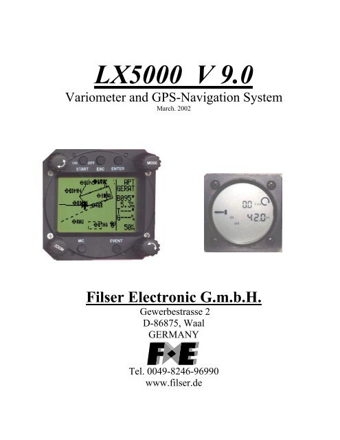
LX5000 V 9.0<br />
Variometer and GPS-Navigation System<br />
March. 2002<br />
<strong>Filser</strong> <strong>Electronic</strong> G.m.b.H.<br />
Gewerbestrasse 2<br />
D-86875, Waal<br />
GERMANY<br />
Tel. 0049-8246-96990<br />
www.filser.de
1 Contents<br />
page 1<br />
LX5000 March 2002<br />
1 CONTENTS................................................................................................................................................................1<br />
2 GENERAL..................................................................................................................................................................3<br />
2.1 TECHNICAL DATA..................................................................................................................................................3<br />
2.2 ROTARY SWITCHES AND KEYS (BUTTONS).............................................................................................................4<br />
2.2.1 On/Start key..................................................................................................................................................4<br />
2.2.2 Mode selector (rotary switch) ......................................................................................................................4<br />
2.2.3 UP/Down Selector (rotary switch) ...............................................................................................................5<br />
2.2.4 ENTER key ...................................................................................................................................................5<br />
2.2.5 ESC/OFF key................................................................................................................................................5<br />
2.2.6 EVENT key ...................................................................................................................................................5<br />
2.2.7 MC/ BAL key ................................................................................................................................................5<br />
2.2.8 ZOOM (rotary switch).................................................................................................................................5<br />
3 OPERATION MODI .................................................................................................................................................6<br />
3.1 SETUP .................................................................................................................................................................6<br />
3.1.1 SETUP before password ..............................................................................................................................6<br />
3.1.1.1 QNH RES (QNH and safety altitude)........................................................................................................................7<br />
3.1.1.2 LOGGER...................................................................................................................................................................7<br />
3.1.1.3 INIT...........................................................................................................................................................................9<br />
3.1.1.4 DISPLAY ................................................................................................................................................................10<br />
3.1.1.5 TRANSFER.............................................................................................................................................................10<br />
3.1.1.6 PASSWORD ...........................................................................................................................................................10<br />
3.1.2 SETUP after password ..............................................................................................................................10<br />
3.1.2.1 TP (Turn point)......................................................................................................................................................10<br />
3.1.2.2 OBS. ZONE (observation zone) .............................................................................................................................11<br />
3.1.2.3 GPS..........................................................................................................................................................................15<br />
3.1.2.4 UNITS .....................................................................................................................................................................15<br />
3.1.2.5 GRAPHIC................................................................................................................................................................16<br />
3.1.2.6 PILOTES (Piloten Namen Eigabe).........................................................................................................................17<br />
3.1.2.7 NMEA .....................................................................................................................................................................18<br />
3.1.2.8 PC ............................................................................................................................................................................18<br />
3.1.2.9 DEL TP/TSK ...........................................................................................................................................................19<br />
3.1.2.10 POLAR................................................................................................................................................................19<br />
3.1.2.11 LOAD..................................................................................................................................................................19<br />
3.1.2.12 TE COMP. ..........................................................................................................................................................19<br />
The LX5000 offers two methods of vario TE compensation.....................................................................................................19<br />
3.1.2.13 AUDIO................................................................................................................................................................20<br />
3.1.2.14 INPUT (Speed command external switch) .........................................................................................................20<br />
3.1.2.15 LCD IND. (LCD – vario indicator)....................................................................................................................21<br />
3.1.2.16 COMPASS ..........................................................................................................................................................22<br />
3.1.2.17 ENL.....................................................................................................................................................................22<br />
3.1.2.18 PAGE 1 (main navigation page)..........................................................................................................................22<br />
3.1.2.19 PAGE 3 (additional navigation page).................................................................................................................23<br />
3.2 NAVIGATION FUNCTIONS ....................................................................................................................................23<br />
3.2.1 GPS page....................................................................................................................................................23<br />
3.2.2 NEAR AIRPORT.........................................................................................................................................24<br />
3.2.3 APT Airports ..............................................................................................................................................25<br />
3.2.3.1 Navigation in APT...................................................................................................................................................25<br />
3.2.3.2 Airport selection, team function and wind calculation.............................................................................................26<br />
3.2.4 TP (turnpoints) ...........................................................................................................................................28<br />
3.2.4.1 TP select ..................................................................................................................................................................28<br />
3.2.4.2 TP EDIT ..................................................................................................................................................................29<br />
3.2.4.3 TP NEW ..................................................................................................................................................................29<br />
3.2.4.4 TP delete..................................................................................................................................................................29<br />
3.2.4.5 TEAM......................................................................................................................................................................30<br />
3.2.4.6 WIND ......................................................................................................................................................................30<br />
3.2.4.7 TP QUICK (memorizing of actual position)............................................................................................................30
page 2<br />
LX5000 March 2002<br />
3.2.5 TSK (task)...................................................................................................................................................30<br />
3.2.5.1 TSK select ...............................................................................................................................................................31<br />
3.2.5.2 TSK edit .................................................................................................................................................................31<br />
3.2.5.3 Task new..................................................................................................................................................................33<br />
3.2.5.4 DECLARE...............................................................................................................................................................33<br />
3.2.6 Statistics .....................................................................................................................................................34<br />
3.2.6.1 Flight statistics.........................................................................................................................................................34<br />
3.2.6.2 TSK Statistics ..........................................................................................................................................................34<br />
3.2.6.3 LOG BOOK.............................................................................................................................................................35<br />
3.2.6.4 Statistics after flight.................................................................................................................................................35<br />
3.3 VARIOMETER ......................................................................................................................................................37<br />
3.3.1 Vario...........................................................................................................................................................37<br />
3.3.2 Altimeter.....................................................................................................................................................37<br />
3.3.2.1 IGC barogram recalibration procedure ....................................................................................................................37<br />
3.3.3 Speed command..........................................................................................................................................38<br />
3.3.4 Final glide calculator.................................................................................................................................38<br />
3.4 FLYING WITH THE LX5000 .................................................................................................................................38<br />
3.4.1 Switching ON and selecting pilot ...............................................................................................................38<br />
3.4.2 SET ALT (take off elevation input) ............................................................................................................39<br />
3.4.3 Preflight check............................................................................................................................................39<br />
3.4.4 Performing the flight ..................................................................................................................................39<br />
3.4.4.1 Preparing a task .......................................................................................................................................................40<br />
3.4.4.2 Starting a task ..........................................................................................................................................................41<br />
3.4.4.3 Automatic switch over.............................................................................................................................................41<br />
3.4.4.4 Using the MOVE function.......................................................................................................................................41<br />
3.4.4.5 TSK END ................................................................................................................................................................42<br />
3.4.4.6 Procedure after landing............................................................................................................................................42<br />
3.4.4.7 SIMPLE TASK........................................................................................................................................................42<br />
4 PC AND LOGGER COMMUNICATION.............................................................................................................43<br />
4.1 COMMUNICATION WITH PC.................................................................................................................................43<br />
4.2 COMMUNICATION LX5000 – LX 20, COLIBRI....................................................................................................44<br />
5 INSTALLATION .....................................................................................................................................................45<br />
WIRING...........................................................................................................................................................................47<br />
TREE STRUCTURE DIAGRAM ...........................................................................................................................................48<br />
6 PASSWORDS...........................................................................................................................................................49<br />
7 OPTIONS..................................................................................................................................................................50<br />
7.1 LX5000 COMPASS MODULE...............................................................................................................................50<br />
7.1.1 General.......................................................................................................................................................50<br />
7.1.2 Installation of the compass module ............................................................................................................51<br />
7.1.2.1 where to install: .......................................................................................................................................................51<br />
7.1.2.2 First test after installation: .......................................................................................................................................51<br />
7.1.3 Adjusting the compass module:..................................................................................................................51<br />
7.1.4 final test:.....................................................................................................................................................52<br />
7.1.5 Windcalculation during flight.....................................................................................................................52<br />
7.2 LX5000 –REMOTE CONTROL UNIT......................................................................................................................53<br />
7.2.1 General.......................................................................................................................................................53<br />
7.2.2 Getting started............................................................................................................................................53<br />
7.2.3 Electonical connection ...............................................................................................................................54<br />
8 REVISION HISTORY.............................................................................................................................................54
2 General<br />
page 3<br />
LX5000 March 2002<br />
The instrument consists of two units, the main unit (80 mm) and LCD Vario indicator (57 mm). Additional LCD Vario<br />
indicators can be added.<br />
The fast calculation processes and graphic displays are achieved by using modern microcontroller technology. The<br />
sensors are modern, highly precise, temperature compensated pressure sensors for altitude and speed to eliminate errors<br />
Vario functions<br />
• Vario, Netto, Relative and Average<br />
• Speed command<br />
• Final glide calculator<br />
• TE compensation (TE-tube or electronic)<br />
Navigation functions:<br />
• Jeppesen airport and database or Europe (up to 5000 airports)<br />
• 600 turnpoints<br />
• 100 tasks<br />
• Statistics<br />
• Near airport function<br />
The manual is written for all instruments having program version 9.x and also for all the instruments being hardware<br />
upgraded from 6.x to 8.x or 9.x<br />
What does LX5000FAI mean?<br />
LX5000 FAI has abuilt in approved IGC logger and therefore one additional pressure sensor for altitude. Special<br />
software on the device is responsible for stored data integrity, which means no manipulation is possible.<br />
2.1 Technical data<br />
• Power 8-16 V DC<br />
• Consumption 400mA/12V (without audio)<br />
• 80 mm std Aircraft cut-out main unit.<br />
• 57 mm std. Aircraft cut-out LCD unit.<br />
• Length 200 mm (incl. connector)<br />
• NMEA output<br />
• Winpilot interface<br />
• 12 Channel GPS receiver<br />
• External speaker<br />
• Data compatible with LX 20 and Colibri<br />
• IGC logger.<br />
• PC communication<br />
• Wiring<br />
• Additional LCD Vario could be connected via 485 bus<br />
• Weight: 800g
2.2 Rotary switches and keys (buttons)<br />
The following control elements are mounted on the main unit<br />
• Four rotary switches (selectors)<br />
• Five keys (push buttons)<br />
The LCD-Vario is designed as a slave unit, which means it has no control switches and keys.<br />
ON, start key ESC /OFF key ENTER key<br />
Audio volume<br />
ZOOM selector<br />
MC input key<br />
page 4<br />
LX5000 March 2002<br />
MODE selector<br />
Display<br />
UP/DOWN selector<br />
EVENT key<br />
2.2.1 On/Start key<br />
A short press on ON/Start key will switch the instrument ON. To switch the instrument off hold ESC/OFF key for a few<br />
seconds and the instrument will be switched off. To switch the instrument off during the flight it needs a confirmation<br />
from the pilot, so the LX5000 cannot be switched off by mistake.<br />
IMPORTANT!<br />
After having a short power brake during flight and the instrument will be off for a few seconds, it will not produce two<br />
flights.<br />
During flight the key is used to start the task, to see more characters of airport names and, in the edit menu, to go one<br />
step back if e.g. an error has been made (see paragraph APT).<br />
2.2.2 Mode selector (rotary switch)<br />
The mode selector is used to change modes of operation. This switch has the highest priority in the system. Whenever<br />
it is activated a mode changeover will happen.
page 5<br />
LX5000 March 2002<br />
2.2.3 UP/Down Selector (rotary switch)<br />
This rotary switch has a lower priority than the mode selector switch and is active all the time in the selected mode. It is<br />
mainly used for selecting sub menus during navigation and to scroll in the edit menu.<br />
2.2.4 ENTER key<br />
The main function of this key is confirmation and to start edit procedures.<br />
2.2.5 ESC/OFF key<br />
This is a multifunctional key, which has two main functions.<br />
• After ESC is pressed a jump to the menu of the next higher level will follow<br />
• During the input of letters and numbers (blinking cursor) ESC confirms the whole row (not necessary to press<br />
ENTER few times)<br />
2.2.6 EVENT key<br />
Activates the Event function (see Chapter 3.1.1.2, LOGGER)<br />
2.2.7 MC/ BAL key<br />
Provides Mc Cready (MC) and ballast setting. The ballast setting is possible after a double click. The value is changed<br />
with the UP/DOWN-selector. (In the elder series of LX5000 there are two separat rotary switches for MC and ballast)<br />
2.2.8 ZOOM (rotary switch)<br />
This is a multifunctional rotary switch. Its main function is to change the zoom level in the graphic mode. Additionally<br />
the zoom switch is used as follows:<br />
• To select turnpoints (only in TP main page)<br />
• After a mistake during editing it is possible to go back some stages by rotating this knob (only when the cursor is<br />
blinking = editing is active)
3 Operation modes<br />
page 6<br />
LX5000 March 2002<br />
The LX5000 has 7 modes or main menus. All of them are selected directly by rotating the mode selector. The diagram<br />
shows the menu (mode) structure of LX5000.<br />
⇐MODE⇒<br />
GPS NEAR APT TP TSK STATISTICS SETUP<br />
⇓ ⇓ ⇓ ⇓ ⇓<br />
⇓ ⇓ ⇓ ⇓ ⇓<br />
Navigation menus (APT, TP,TSK) have sub menus, which are selected using up/down selector.<br />
GPS GPS status, no inputs<br />
NEAR Near airport, choose one airport, no further inputs available<br />
APT Navigation and selection of airports<br />
TP Navigation, selection and edit of turnpoints<br />
TSK Navigation, selection and edit of task<br />
STAT Flight statistic and logbook<br />
SETUP is organized in two levels. The first level (no password required) is accessible for everybody. For the second<br />
level, the pilot has to use the password. The password is not a top secret; it is the same for all instruments and published<br />
(in fact it is the last five nimbers of the <strong>Filser</strong> GmbH telephone number)<br />
96990<br />
After installation of the LX5000, it is necessary to activate the password and adjust the settings of the instrument and the<br />
desired units.<br />
3.1 SETUP<br />
3.1.1 SETUP before password<br />
Changes can be made at any time. This first level contains no system settings at all.<br />
The up/down selector will select the different menus.
3.1.1.1 QNH RES (QNH and safety altitude)<br />
page 7<br />
LX5000 March 2002<br />
After switching on, the pilot has an opportunity to input the actual QNH, taken from meteorological service. Using this<br />
feature it is possible to offset the altitude datum, which could have been changed due to pressure changes during the<br />
flight. Without input of initial QNH before the flight, this function is not active.<br />
Any change of the QNH influences the measured altitude. A wrong setting can therefore cause an unprecise final glide.<br />
Procedure:<br />
• Use the up/down selector to choose the item (QNH, ALT.R. MG.VAR. or BUGS)<br />
• Press ENTER<br />
• Use up/down and ENTER for input<br />
• Close the procedure with ESC<br />
Some GPS receivers don’t deliver magnetic variation (MG.V.). In that case the input of a typical value of variation for<br />
the area flown in is obligatory, especially if the magnetic compass is used for wind calculation, or magnetic track is used<br />
in navigation. Having a receiver, delivering variation, no input is possible and necessary (AUTO message will appear)<br />
Example above: safety altitude 000m, QNH offset not possible.<br />
“BUGS” is polar degradation because of “buggy” wings. The input is in glide ratio degradation percentage.<br />
(5%, means glide ratio degradation is 5%)<br />
3.1.1.2 LOGGER<br />
As mentioned before, the flight recorder (logger) is approved by the IGC commission. ( Governed by the FAI.)<br />
After “enter” the LOGGER will follow.<br />
to<br />
Under “FLIGHT INFO” all important data, such as pilot (name), glider type, call sign, competition sign and comp.<br />
class are stored. Also the name of the official observer can be entered. After pressing ENTER on FLIGHT INFO all<br />
these parameters are accessible. Naturally all these settings are available with a PC and the Lxe-program or via Colibri<br />
or LX20 (see Chapter 4). The settings are performed with ENTER UP/DOWN and ESC.<br />
Example:<br />
Please note, there is an important change compared to earlier versions: With the version 9.0 the glider<br />
type, set under Setup ->Password -> Polar, see 3.1.2.10, is automatically written into the IGC file-header.<br />
If one likes to fly with a polar other than that of the used glider, one should write the parameters of that polar<br />
into the user polar and should term it with the name of the used glider (important at decentralized competitions,<br />
Online-Contest, Barron-Hilton-Cup...)
Before leaving the FLIGHT INFO menu one can save the pilot´s data in a pilot list.<br />
page 8<br />
LX5000 March 2002<br />
Confirming with Y(es) stores the pilot into the pilot list, what means this pilot can be chosen during the start-up<br />
procedure.<br />
Important !<br />
If the the pilot is not added to the list (ADD PILOT TO LIST N) one has the private pilot modus. In this case the<br />
LX5000 offers no choice of pilots and after 30sec the SET ELEVATION procedure is started.<br />
On the other hand, having added more than one pilot to the list, a pilot can be chosen out of the list during the boot<br />
procedure (Choose with UP/DOWN and confirm with ENTER). This is called the Multi-Pilot Option. For details see<br />
chapter 3.4.<br />
LOGTIME is an important setting for sufficient flight recording.<br />
TOTAL MEMORY is the capacity of memory and depends on the settings only. This number is not reduced after some<br />
flights are stored. It changes only after new settings have been made in the setup. The total memory indicates how many<br />
hours of flight can be flown without loosing the flight data because of overwriting. If the memory is full, the oldest<br />
flights will be overwritten without warning.<br />
B-RECORD: position, GPS altitude, pressure altitude, UTC and GPS status are recorded<br />
Pilot sets record interval, the default value is 12 seconds.<br />
K-RECORD: not active by default<br />
NEAR TP INT.: being close to the turnpoint (inside NEAR RAD), the logging runs faster<br />
NEAR TP RAD.: radius that defines NEAR<br />
(I) RECORD<br />
Using this record some more flight parameters can be logged. Setting Y activates additional logging.<br />
-FXA: current horizontal accuracy of GPS<br />
-VXA: current vertical accuracy of GPS<br />
-RPM: engine RPM<br />
-GSP: groundspeed<br />
-IAS: indicated airspeed<br />
-TAS: TAS<br />
-HDM: mg. heading<br />
-TRM: magnetic track<br />
-TRT: true track<br />
-TEN: total energy<br />
For motor gliders ENL: Y
-WDI: wind direction<br />
-WVE. wind<br />
-VAR: vario<br />
-ENL: engine noise level (Must be Y when flying powered gliders)<br />
Each activated setting will reduce the total memory capacity.<br />
(J) RECORD<br />
page 9<br />
LX5000 March 2002<br />
J record has the same settings as I record, but will build a separate file. Using this record reduces the total memory<br />
significant.<br />
EVENT<br />
After pressing EVENT key, the logger will run a limited time faster as defined in LOGTIME. Activation of EVENT is<br />
recorded as a special record in the IGC file. Some competition rules require using EVENT before departure.<br />
Example: after EVENT, 30 additional fixes will be logged in 2-second interval.<br />
3.1.1.3 INIT<br />
The following parameters can be re-defined using this setting.<br />
• VARIO FIL: damping of vario indicator from 0.5 up to 5, default setting is 1.0 (nominal seconds)<br />
• VARIO INT: vario average time, 20 seconds default<br />
• VARIO RNG: vario range<br />
• TAB: audio dead zone during speed command flight<br />
• ETA: Calculation of the estimated arrival time: GS based on the actual groundspeed, VAR based on<br />
the averaged variometer value of the complete flight so far, Mc based on the actual Mcsetting.<br />
• AUTO SC: speed command change-over method<br />
OFF: only with external switch<br />
GPS: after climbing ( circling) is detected using GPS, an automatically change over will<br />
happen<br />
XXX: TAS in 5 km/h steps from 100 up to 160 km/h (knts, mph)<br />
• WIND/COMPASS: compass is an optional device which can be connected to the LX5000 485 bus. The device<br />
delivers magnetic track and one additional wind calculation method can be used. The method<br />
needs a straight flight. The time for calculation is set using this menu (normal 15 seconds).<br />
Longer time means a better wind calculation.
3.1.1.4 DISPLAY<br />
page 10<br />
LX5000 March 2002<br />
The contrast depends on the viewing angle of the pilot and on climatic factors (daylight intensity and temperature). To<br />
adjust it use this setting. To change the contrast rotate the up/down selector.<br />
3.1.1.5 TRANSFER<br />
To communicate with PC, LX 20 or Colibri use this menu. Data transfer is started after ENTER, for detailed information<br />
see Chapter 4.<br />
3.1.1.6 PASSWORD<br />
Sytem settings can be obtained, after entering the password (for detailed description see next paragraph 3.1.2)<br />
96990<br />
3.1.2 SETUP after password<br />
After password input (96990) further 19 system settings are available. During the flight the password is inactive, that<br />
means after ENTER on password the LX5000 jumps directly into the setup menu!<br />
3.1.2.1 TP (Turn point)<br />
All settings dealing with turnpoints can be done in this menu. The LX5000 is able to store 600 turnpoints.<br />
TP-QUICK POINT NAME<br />
The pilot is able to store his actual position during the flight. Such turnpoints are called QUICK TP and are generally<br />
named like AP (actual point). How to store the actual position will be described later.<br />
Settings:<br />
DATE OFF will store the position like AP: 12:35. The numbers show the time of storing.<br />
DATE ON will store the position under date and time (28121330 for 28 dec. 13:30).<br />
To store the actual position, the START key should be pressed in TP mode.<br />
TP-QUICK POINT – AUTO<br />
SELECT: OFF after stored, the actual position will not be selected automatically<br />
SELECT: ON after stored, the actual position will be selected automatically and ready for navigation<br />
NEAR RADIUS<br />
The setting has nothing to do with the setting described in LOGGER. The LX5000 has a very useful function named<br />
„Simple task“. This function is active when a regular task is started. The instrument will detect being close to the<br />
turnpoint and after reaching of distance smaller than NEAR RADIUS, the turnpoint will be taken like a confirmed TP of
page 11<br />
LX5000 March 2002<br />
simple task. Simply said, flying from TP to TP would build a nice in-flight statistics and useful flight evaluation on the<br />
ground. For more information on this see Chapter 3.4, flying with the LX5000.<br />
TP-SORT<br />
The LX5000 is able to sort the turnpoints under alphabet or under distances (some kind of NEAR TP function). Being<br />
sorted under distance the nearest TP will appear, after starting of the select procedure.<br />
3.1.2.2 OBS. ZONE (observation zone)<br />
In this menu the different sector geometries for different kinds of tasks and competitions can be programmed.<br />
The following sectors can be programmed:<br />
• Sector for task start (START ZONE)<br />
• Sector at the turn points (POINT ZONE)<br />
• Finish line (FINISH ZONE)<br />
• Templates<br />
Templates are predefined geometries, where all sectors are programmed identically. Actual only 90 0 -photosector and<br />
500m-cylinder are available.<br />
The programming of the sectors is generally done by defining two angles, two radii and the direction of the sectors<br />
symmetry axis (either by a fixed value or by automatic definition). The settings done here are “global”, that means this<br />
definition is valid for all tasks. For 5 (five) tasks it is possible to program special sectors, even for the single turnpoints<br />
of one task. This is done “local” at the corresponding task in the task menu. A very useful function, when flying AAT<br />
(Assigned Area Task). The programming of a special sector for each point is necessary for the “Assigned Area Tasks”.<br />
These (lokal) settings are done in the same way as they are described here. Where they have to be programmed, you can<br />
read in chapter 3.2.4.<br />
Note: When working again in the SETUP OBS. ZONE menu after having defined “local” AAT-sectors, all these<br />
locals sectors are overwritten with the global values defined here!!<br />
The basic principle of defining the sectors is done as follows:<br />
3.1.2.2.1 START ZONE<br />
To adjust the start zone, select the menu item START ZONE with [ENTER]. We get the following screen:<br />
• HDG: defines orientation of the symmetry axis of the sector.<br />
• A21: Direction of the symmetry axis (in most cases AUTO)<br />
• R1: Radius of the sector, e.g. 3km for the FAI photo sector.<br />
• A2: Like A1, used for creating combined sectors.<br />
• R2: Like R1, also used for combined sectors
page 12<br />
LX5000 March 2002<br />
At first, this sounds very complicated, but some examples shall help you to understand the meaning of these settings.<br />
Example 1:<br />
In the default settings the 90°-FAI photo sector is set as start zone (see picture above), which means HDG is set to “TO<br />
NEXT POINT”. The start zone is therefore symmetrical about the bearing to the next turnpoint.<br />
A21 is set to AUTO, which is clear because the direction of the symmetry axis of the start zone is identical to the<br />
bearing to the first turnpoint. If A21 is set to AUTO, it’s impossible to select this item and change its value.<br />
A1 is 45°, because the half-angle is entered.<br />
R1 is 3km.<br />
A2 and R2 are both set to 0, that means: not programmed.<br />
Example 2:<br />
A 180°-start zone with 20km diameter is programmed the following way:<br />
HDG: TO NEXT POINT<br />
A21: AUTO<br />
A1: 90 0<br />
R1: 10km<br />
A2: 0 R2: 0<br />
Note:<br />
According to the IGC competition rules of May 2000 the current start sector for international championships is the<br />
classical start line. Because the LX5000 can’t deal with a simple start line but needs a start sector, you use the 180°sector<br />
of example 2. The only disadvantage: For the LX5000 it’s sufficient to fly at least once into the sector so that the<br />
device accepts your start as valid. It makes no difference in which direction you leave the sector, but for the sports<br />
committee, it does!! You definitely need to cross the front line to get a valid start! (see picture below)<br />
Start 1: not valid with start<br />
line<br />
Start 2: valid with start line<br />
Start 3: valid with start line<br />
Start 4: not valid with start<br />
line<br />
Therefore we recommend that you control your crossing of the line having the graphics page displayed.
page 13<br />
LX5000 March 2002<br />
Further settings possible for HDG:<br />
• R.FROM 1.TP: This sort of start sector was planned for the world gliding championships 1999 in Bayreuth. A<br />
radius is drawn around the first turnpoint through the start point and a radial segment of a certain length is cut out<br />
symmetrically around the start point. The advantage of this system is that a pilot starting far outside at the end of<br />
that line has to fly the same distance to the first turnpoint as a pilot starting in the "middle". This is contrary to the<br />
classical start line where the distance to the first turnpoint is increasing the more one starts further from the center<br />
of that line.<br />
A21: is fixed here to AUTO<br />
A1: is without function, only R1, which defines here the length of the segment, is of interest<br />
R1: describes the half-length of this segment<br />
A2: has no function here<br />
R2: two radials from the first turnpoint to the ends of the segment are constructed and elongated with R2. A<br />
second segment is drawn through these two new points. Together this defines a start sector by using two<br />
segments<br />
• FIXED VALUE: The direction of the symmetry axis of the sector is adjusted to a fixed bearing. This bearing is<br />
entered as A21. The setting FIXED VALUE is normally not used for start sectors, but sometimes for finish zones<br />
(see “FINISH ZONE”).<br />
Note:<br />
Please be aware that all the examples are intended to explain the programming procedures and therefore cannot claim<br />
absolute accuracy and completeness. For each kind of competition different types of sectors and rules for the correct<br />
documentation of these sectors may apply, which can be found in the particular competition rules. In case of doubt, the<br />
rules pertaining are defined in the FAI Sporting Code Section 3. E.g. For most of the national decentralised<br />
championships the start sector consists of the 90 0 -photosector, for FAI-badges, 1000/2000km-diplomas and Barron-<br />
Hilton-Cup only the 90 0 -photosector is allowed. For record flights a 1000m startline is used for recording the start time.<br />
3.1.2.2.2 POINT ZONE<br />
Now select the item POINT ZONE of OBS. ZONE. You will get the same options as for the START ZONE. The only<br />
difference is that you get more options for the settings of HDG. The current competition rules require a 500m-cylinder,<br />
so that the direction of the symmetry axis is not important. Nevertheless, all the possible settings are explained here,<br />
because in decentralised competitions or for record flights other sectors are valid:<br />
• SYMMETRICAL: The symmetry axis of the turnpoint sector is orientated symmetrically about the line bisecting<br />
the inbound leg from the previous turnpoint and the outbound leg to the next turnpoint.<br />
• TO PREV POINT: The symmetry axis is directed to the previous turnpoint. This option was intended for Cats<br />
Cradle and related tasks.<br />
• TO NEXT POINT: The symmetry axis is directed to the next turnpoint. This option was intended for Cats Cradle,<br />
too.<br />
• TO START POINT: The symmetry axis is directed to the start point. Again a Cats Cradle option.<br />
• FIXED VALUE: The symmetry axis can be adjusted to any direction. This is the only option for which A21 is not<br />
set to AUTO.<br />
Example 3:<br />
We want to adjust the currently valid sector for the German decentralised competition (DMSt) until 2001 (from 2002<br />
with the DMSt online only the 90 0 fotosector is valid). This is the 90°-photo sector combined with the 500m-cylinder:
HDG: SYMMETRICAL<br />
A21: AUTO<br />
A1: 45 0<br />
R1 3.0km<br />
A2: 180 0<br />
R2: 0.5km<br />
page 14<br />
LX5000 March 2002<br />
Note:<br />
Please note that combined sectors must be programmed with the smaller radius for A2 and R2 (R1>R2!!). It’s therefore<br />
impossible to program the figure of example 3 in just the reverse order.<br />
Note also:<br />
For record flights, FAI badges, 1000/2000km-diplomas and for the Barron-Hilton-Cup only the 90°-photo sector is<br />
valid, not the 500m-cylinder!! For some of the national decentralised competitions the combined figure consisting of<br />
90 0 -photosector and 500m-cylinder is valid.<br />
3.1.2.2.3 FINISH ZONE<br />
Select the item FINISH ZONE and confirm with [ENTER]. Although you get the same screen as for the previous items,<br />
there are only two options for HDG here:<br />
• TO LAST LEG: The symmetry axis is directed back to the last turnpoint. This is the usual setting for<br />
decentralised competition flights.<br />
• FIXED VALUE: The symmetry axis can be set to any direction (see example 4).<br />
Example 4:<br />
In a competition the finish line is orientated perpendicular to the runway’s direction, independent from the bearing to the<br />
last turnpoint. The airfield’s runway has the direction 06/24.<br />
We select HDG: “FIXED VALUE” and can enter either 060° or 240° for A21, depending on the direction of the final<br />
glide. For example for a final glide in the direction 270° we have to enter A21: 060°. Now the “flat side” of the sector is<br />
directed back to the last leg (see picture below), the glider will enter the sector crossing the line.<br />
Note:<br />
There are many ways to complete a flight. For decentralised competitions, record flights etc. the advice of the FAI<br />
Sporting Code should be enough. E.g. when flying BHC, badges, diplomas etc it is enough to land inside the airfield<br />
borders if the airfield is the finish point, while if one is using an external finish point, then the appropriate sector must<br />
be used (according the sporting code, the latter can be done in any case), but care should be taken to remember which<br />
one has to be used.
3.1.2.2.4 TEMPLATES<br />
page 15<br />
LX5000 March 2002<br />
Templates are predefined sector geometries. Only the 500m-cylinder and the 90 0 -FAI-photosector are available.<br />
Note: Using one of these templates, the LX5000 will overwrite all user-defined sectors with the chosen template,<br />
there will be no additional confirmation!!<br />
3.1.2.3 GPS<br />
The pilot is able to set local time for his navigation.<br />
IMPORTANT!<br />
UTC offset has absolutely no influence on time logged in the logger. Logger always uses UTC.<br />
It is not possible to change the GPS earth datum. For IGC loggers WGS 1984 is obligatory.<br />
3.1.2.4 UNITS<br />
Practically all known units and combinations can be used in the LX5000.<br />
• LAT, LON: decimal minutes or seconds<br />
• DIST: km, NM, ml<br />
• SP (speed) km/h, kts, mph<br />
• VARIO: m/s, kts<br />
• HDG: magnetic or true<br />
• WIND: km/h, kts, mph, m/s<br />
• ALTITUDE: m, ft<br />
• QNH: mb, mm, in<br />
• LOAD: Overload, kg/m 2 , lb/ft 2<br />
Glider + Pilot + Ballast<br />
OVERLOAD = --------------------------------<br />
Glider + Pilot<br />
Example:<br />
Overload 1.2 means that the take off weight is 20% higher than unballasted.
3.1.2.5 GRAPHIC<br />
page 16<br />
LX5000 March 2002<br />
The graphic display of the LX5000 offers valuable information, selected by the user. In order not not to overload the<br />
display some care should be taken by enabling only relevant airspace.<br />
SYMBOL<br />
The LX5000 graphic display supports two sizes of glider symbol. Rotate UP/DOWN selector to select the glider symbol.<br />
Additionally the flown track of the last x minutes can be shown as a line (This is entered under TAIL LENGTH). 0min<br />
means no line<br />
AIRSPACE<br />
This is a very important setting, which allows the pilot to define under what conditions the airspace will be shown on the<br />
display. The instruments are delivered with airspace DISABLE that means no airspace on the display at all. To enable<br />
airspace set ENABLE at first. There are 5 different types of airspace. Each has a different type of line to allow visible<br />
separation of different zones. The zones can be present all the time (setting ON) or closed by setting OFF. Using setting<br />
ON for all kinds of airspace will overload the display, so we offer to use settings, which are connected with zoom.<br />
Example<br />
Using setting for instance 50 km will show the airspace only at zoomfactor 50 km and lower. If the zoom is bigger than<br />
50 km the particular airspace will not be active.<br />
The following settings are recommended therefore preset as factory default:<br />
• CTR. control zone<br />
• R.P,D restricted, prohibited, dangerous<br />
• TRA training zone<br />
• TIZ traffic information zones<br />
• TMA terminal zone<br />
APT<br />
Airspace type<br />
The airports are displayed like symbols with names.<br />
Active, when zoom is 50 km or less<br />
APT ZOOM: 50 km setting will show the airports only having zoom 50 km or lower, if the zoom is bigger than 50 km<br />
the airports will disappear completely in order to avoid an overload of the display (available settings ON, OFF, 5,10, 20,<br />
50, 100 km)
page 17<br />
LX5000 March 2002<br />
APT NAME: The airports are not displayed only with symbols, some letters of the name or ICAO code can be added.<br />
The pilot is able to choose between:<br />
• ICAO will show ICAO code of the airport close to the symbol<br />
• 2 char. up to 8 char. will display first letters of the airport<br />
• NONE, without letters, only symbol<br />
TP:<br />
The same logic is used for displaying of turnpoints .<br />
There are four types of turnpoints and each type has a different symbol on the screen.<br />
• T. POINT simple turnpoint (landing isn't possible)<br />
• AIRPORT turnpoint with all airport functions<br />
• OUTLAND turnpoint as an outlanding place<br />
• MARKER is not a permanent turnpoint, it is deleted when the instrument is switched off. It can be used to mark<br />
thermals for instance.<br />
IMPORTANT!<br />
The turnpoints marked landable will appear in the NEAR AIRPORT, displayed with corresponding symbols in front of<br />
the name (airport, outlanding).<br />
3.1.2.6 PILOTES (Piloten Namen Eigabe)<br />
The LX5000 version 9.0 supports a so called multi pilot function. The names of max. 30 pilots can be stored to a pilot<br />
list. This list is active as soon as the first pilot was entered under FLIGHT INFO and than copied into the pilot list. (see<br />
chapter FLIGHT INFO)<br />
Password is a pilot specific alphanumeric input, which enables every pilot to save his specific settings and to reactivate<br />
them during the start up procedure by choosing his name and entering his password. The actual values are stored under<br />
the name of the active pilot before switching off and can be reactivated when the device is switched on again (see<br />
above).<br />
The following values are stored in the individual setting:<br />
• final glide: RESERVE height<br />
• Flight Info<br />
• Settings under LOGGER<br />
• INIT<br />
• Display<br />
Under password:<br />
• TP<br />
• OBSERVATION ZONES<br />
• GPS<br />
• UNITS<br />
Marker, that this pilot<br />
was chosen during the<br />
start up procedure
• GRAPHIC<br />
• NMEA<br />
• PC<br />
• POLAR<br />
• LOAD<br />
• TE COMP.<br />
• AUDIO<br />
• INPUT<br />
• LCD INDICATOR<br />
• PAGE 1<br />
• PAGE 3<br />
Editing and adding more pilots „by hand“ is possible by pressing ENTER:<br />
page 18<br />
LX5000 March 2002<br />
The function INSERT allows adding of more pilots (Up to 30). The message Active (upper right corner) indicates that<br />
specific settings of th shown pilot are active (means that this pilot has been chosen in the startup procedure).<br />
Important!<br />
Having entered a new pilot switch the LX5000 off and then on again and chose the desired pilot.<br />
A new entry can also be performed by entering that pilot into the FLIGHT INFO and copying to the pilot list.<br />
3.1.2.7 NMEA<br />
LX5000 delivers position data in the NMEA-format to other navigation devices in the cockpit if necessary.<br />
All NMEA sentences are not active in default settings that means the pilot has to activate them if necessary. Normally<br />
GGA, RMC, and RMB are used. The pilots using WinPilot should activate LXWP_ also. Please see manual of your<br />
external device for information about the needed protocolls.<br />
The data is available as Tx line on 9P sub D connector marked RS 232, see wiring.<br />
3.1.2.8 PC<br />
The speed of data transfer between LX5000 and other devices (PC, LX 20 or Colibri) can be adjusted in this menu. It is<br />
very important that both devices have the same communication speed.<br />
The new Windows PC program Lxe is able to adapt the communication speed automatically. The old DOS programs<br />
(LXGPS and LXFAI) are not able to do that.
3.1.2.9 DEL TP/TSK<br />
After Y all turnpoints and tasks will be deleted.<br />
3.1.2.10 POLAR<br />
Polars for nearly all gliders are in the library. To select them simply rotate UP/DOWN selector<br />
page 19<br />
LX5000 March 2002<br />
The parameters a, b, and c of the glider polar can be calculated very simply by the pilot using LXPOLAR or<br />
POLAR.EXE, if the glider polar is not found in the library. After POLAR.EXE is started and three adequate points of<br />
the polar (Apr. 100 km/h, 130 km/h, 150 km/h) are entered, the parameters are calculated automatically. POLAR.EXE is<br />
delivered on the CD together with LXFAI. There is space for two USER polars (rotate UP/DOWN to the left).<br />
Please note, there is an important change compared to earlier versions: With the version 9.0 the glider type,<br />
set under Setup ->Password -> Polar, see 3.1.1.2, is automatically written into the IGC file-header.<br />
If one likes to fly with a polar other than that of the used glider, one should write the parameters of that polar into<br />
the user polar and should term it with the name of the used glider (important at decentralized competitions, Online-<br />
Contest, Barron-Hilton-Cup...)<br />
Name „user“ should of course be replaced with the glider’s name, to have the correct glider type in the IGC-header<br />
3.1.2.11 LOAD<br />
Normally the ballast setting is brought to minimum after the LX5000 has been switched off. Using setting SWITCH ON<br />
LOAD: SET, the load setting will remain the same as the last setting done in the previous flight.<br />
3.1.2.12 TE COMP.<br />
The LX5000 offers two methods of vario TE compensation.<br />
• TE tube<br />
• <strong>Electronic</strong> TE compensation
page 20<br />
LX5000 March 2002<br />
TE setting 0% declares compensation using the TE tube<br />
Using the tube the instrument has no influence on compensation; it depends only on the quality of the tube.<br />
TE setting >0% = electronic TE compensation<br />
To adjust TE composition at least one flight in not turbulent atmosphere is necessary. The procedure is as follows:<br />
• Accelerate up to 160 km/h and keep the speed stable for a few seconds<br />
• Reduce the speed to 80 km/h<br />
Observe the vario indicator during the maneuver. At the beginning (160 km/h) vario will stay stable aty about. –2 m/s.<br />
During the speed reduction the vario should move toward zero and should never exceed zero. Deviation in + shows that<br />
the compensation is too low, increase % to compensate and vice versa.<br />
TEF (filter) is the delay of compensation. Bigger numbers will increase the delay and opposite. During the first test one<br />
should use delay 6.<br />
If the static of the glider isn’t correct, there is no way to adjust compensation. Having problems we suggest the following<br />
test of the static inputs:<br />
Connect the tubes for the electronic compensation and set at 0%. Accelerate to 160 km/h and reduce the speed. Observe<br />
the vario indicator. If the needle is moving at first more into minus and after that towards +, the static source of the<br />
glider is not suited and there is no way to provide a successful TE compensation electronically. The use of a dedicated<br />
and accurate fin mounted static source might be helpful.<br />
3.1.2.13 AUDIO<br />
The pilot has several choices to adapt the audio to his preference.<br />
• SC: VOL H audio volume will be increased by speed command (H) or decrease by ( L)<br />
• VARIO: several types of audio can be selected (please use AUDIO DEMO)<br />
• 0% frequency at 0 m/s<br />
• +100% frequency at + full deflection<br />
• -100% frequency at – full deflection<br />
3.1.2.14 INPUT (Speed command external switch)<br />
The LX5000 has input for an external speed command switch. Using the external switch it is possible to manually<br />
change over SC/Vario. SC INPUT setting defines what status of the switch will change over to speed command. For<br />
instance ON will change over to speed command immediately after the external switch is closed and vice versa.<br />
An external device called stall warning can be connected to the LX5000. The indicated speed, to activate the alarm, can<br />
be set under STALL W.<br />
The LX5000 is equipped with an external temperature sensor. Temperature ON will enable temperature measurement
and TEMP. OFF. allows precise adjustment (by user) the temperature.<br />
page 21<br />
LX5000 March 2002<br />
There is another input called VARIO PRIORITY. If the input is connected to ground the instrument will change over<br />
into the vario-mode immediately, no matter what other settings might demand.<br />
3.1.2.15 LCD IND. (LCD – vario indicator)<br />
The LCD vario is an autonomous device connected to the 485 bus. Using bus, generally an unlimited number of devices<br />
can be connected to the LX5000. The LX5000 delivers 4 different data sets for the indicators, that means maximum 4<br />
indicators are able to indicate different and the rest of them are simple repeaters.<br />
To adjust viewing angle use contrast setting from LOW to HIGH. The layout of the indicator consists of:<br />
• Needle<br />
• Two numerical displays<br />
• Diverse symbols<br />
NEEDLE<br />
SPEED<br />
COMMAND<br />
RING<br />
LOW BATTERY<br />
INDICATOR<br />
NEEDLE<br />
SHOWS<br />
VARIO NEEDLE<br />
SHOWS<br />
RELATIV<br />
NEEDLE<br />
SHOWS<br />
NETTO<br />
BUGS<br />
INDICATOR<br />
NEEDLE<br />
SHOWS<br />
SPEED<br />
COMMAND<br />
UPPER<br />
NUMBER<br />
DISPLAY<br />
Needle<br />
• SC Ring Always SC indicator, regardless of mode.<br />
• Upper Number Display<br />
• Vario Mode Indicator<br />
• Lower Number Display<br />
• Netto<br />
• Relative<br />
• SC<br />
• GP<br />
VARIO MODE<br />
INDICATOR<br />
SPEED COMMAND<br />
MODE INDICATOR<br />
LOWER<br />
NUMBER<br />
DISPLAY
page 22<br />
LX5000 March 2002<br />
Each indicator has a DIP switch on the backside. The position of the switch defines which data string the indicator<br />
controls.<br />
SW 1 ON Indicator 1<br />
SW 2 ON Indicator2<br />
SW 3 ON Indicator3<br />
all OFF Indicator4<br />
All indicators are by default set to position 1.<br />
The pilot is able to define the functions of the indicators by himself using the following menu.<br />
The needle and two numerical displays are programmable. All settings can be made for vario and speed command<br />
mode separately (VAR NEEDLE =needle in vario mode, SC NEEDLE = needle in SC mode).<br />
Needle settings:<br />
• Vario, SC, NETTO, RELATIVE ( = netto – 0.7 m/s),<br />
Upper digital display:<br />
• Integrator, time, flight time, leg time<br />
Lower digital display:<br />
• ALT (NN altitude), distance, GL DIF. (final glide altitude difference), SPEED (TAS), LEG S. (speed on leg).<br />
3.1.2.16 COMPASS<br />
This unit is optional and has to be ordered as an extra. Power and data are connected via standard LX5000 485 bus.<br />
Without a compass unit connected the COMPAS setting is not active. The LX5000 will recognize the compass<br />
automatically. Compass is used to deliver mg. track to the LX5000. Having mg. track, an additional wind calculation<br />
method can be used and HDG indication will be present.<br />
3.1.2.17 ENL<br />
No settings are possible. The lower (MIC. LEVEL) bar will indicate engine noise level<br />
3.1.2.18 PAGE 1 (main navigation page)<br />
There are three variants of that page and the pilot has to choose the most convenient for him.
Wind komp.<br />
page 23<br />
LX5000 March 2002<br />
The default setting is variant 3, which offers in version 9.0 a calculation of the actual and target glide ratio (SC-mode)<br />
The contents of this page differs, depending on the flight modus (SC or vario)<br />
Vario-mode Speed command mode<br />
3.1.2.19 PAGE 3 (additional navigation page)<br />
This page can only be activated or disabled.<br />
3.2 Navigation functions<br />
The LX5000 has the following navigation functions:<br />
• GPS Status and coordinates<br />
• Near Airport<br />
• APT, Airport<br />
• TP, Turnpoints<br />
• TSK, Task<br />
• STATISTICS separately during the flight and after flight (“Log book”)<br />
All mentioned functions can be selected using the mode selector.<br />
3.2.1 GPS page<br />
Final glide command<br />
Windvector<br />
Altitude<br />
There are no settings possible in this page.<br />
Wind<br />
Final glide<br />
actual glide ratio<br />
Wind vektor<br />
Wind<br />
Netto<br />
Min. glide ratio to<br />
the turnpoint, resp.<br />
goal (TSK)
Rotate the UP/DOWN-selector and both altitudes (m and ft) will appear on the same screen.<br />
Stop watch can be activated and deactivated under following procedure:<br />
• Press START status STOP: 0: 00<br />
• Press START status RUN: 0:12<br />
• Press START status STOP: 0:50<br />
• Press START status STOP: 0:00 Reset<br />
• Press ENTER TIME: 11:56:32 Time again<br />
3.2.2 NEAR AIRPORT<br />
page 24<br />
LX5000 March 2002<br />
The nearest airports will be shown using this mode. The airports are assorted by distance. Simply press ENTER on the<br />
desired airport and the LX5000 will change over to APT mode and all nav. features will be immediately present. To<br />
select the airport use UP/DOWN selector.<br />
IMPORTANT!<br />
COORDINATES<br />
TP with attribut: airfield<br />
TP with attribut: outlanding<br />
Airport from data base<br />
GPS STATUS<br />
ALTITUDE (NN)<br />
TIME<br />
Not only airports are indicated, but all landable turnpoints too. The airports and landable turnpoints are displayed with<br />
different symbols in front of the name. For more information see paragraph turnpoints .
3.2.3 APT Airports<br />
page 25<br />
LX5000 March 2002<br />
This is one of the three main navigation modes (APT, TP, TSK). To change the mode simply rotate themode selector.<br />
The first page shows the basic navigation data (bearing, distance, ground track and ground speed). Additional<br />
information will follow in four more nav.-pages activated using the UP/DOWN selector. The airport memory of LX5000<br />
has a capacity for approx. 5000 airports. The airport data can’t be edited in the instrument; all necessary updates should<br />
be done using a PC. The database used in LX5000 is a <strong>Filser</strong>-licensed Jeppesen database. The database is not free, that<br />
means an update is possible only after getting a code. The code is available through <strong>Filser</strong> <strong>Electronic</strong> only and depends<br />
on the database version and serial number of the LX5000. The database can be downloaded from the Internet using the<br />
following addresses:<br />
www.filser.de<br />
www.lxnavigation.si<br />
3.2.3.1 Navigation in APT<br />
There are five navigation pages and the first one has the following structure.<br />
Bearing<br />
Ground track<br />
Wind vektor<br />
The airport names are normally displayed using 8 characters, after pressing START 12 characters will appear.<br />
IMPORTANT!<br />
TP and TSK have the same basic navigation pages as APT.<br />
Distance<br />
Vario average<br />
Final glide ind.<br />
Wind direction and speed MC and Bal. Dir. indicator Altitude NN<br />
The course correction arrow (Dir. Indicator) will show the pilot where to turn (left or right) to proceed to the desired<br />
airport.<br />
After rotating the UP/DOWN-selector the graphic page will appear. The same page will be found in TP and TSK (in the<br />
TSK-mode the task is additionally displayed)<br />
The airports will be present with symbols and short names or ICAO corresponding to setting in 3.1.2.5.<br />
Airspace<br />
Turning point<br />
Airport ZOOM
page 26<br />
LX5000 March 2002<br />
The glider symbol is all the time in the middle of the screen and the map is moving. To change the ZOOM simply rotate<br />
the ZOOM knob left or right. Following nav. page can be disabled in setup under. PAGE 3.<br />
Desired track<br />
Off course dist.<br />
After rotating of UP/DOWN selector one reaches the so called arrival page<br />
local time<br />
temperature outside<br />
ETA (estimated time of arrival) and ETE (estimated time enroute) define the arrival time and the time needed to reach<br />
the target. Both depend on the settings in the INIT-menu. If there is no way to reach point (track and bearing differ more<br />
than 90 0 ) both times will be replaced with stars. If the windcalculation is not active (depending on the method) the age of<br />
the last windupdate in min is displayed right of the wind.<br />
After rotating of UP/DOWN selector one reaches the last page showing some important airport data.<br />
The traffic circuit is defined like altitude and orientation (N, E…). Orientation I means that it hasn’t been defined.<br />
3.2.3.2 Airport selection, team function and wind calculation<br />
After ENTER an edit menu will appear.<br />
3.2.3.2.1 Airport selection<br />
VOR similar indicator (CDI)<br />
Ground speed<br />
Battery indicator<br />
There are two ways to select an airport. The first direct way is using of ICAO code input. After code input the airport is<br />
selected immediately.<br />
Entering the ICAO-Code for the desired airport is the dircet selection mode. E.g. here München
In case of a mistake use START button (or ZOOM) to step back.<br />
page 27<br />
LX5000 March 2002<br />
If the ICAO-Code is unknown, the indirect way should be used. Simply confirm ICAO with ESC and select the state in<br />
which the airport is located (UP/DOWN selector).<br />
After the state is selected, four stars are to be replaced with first four letters of the airport. All airports with the same first<br />
four letters will be shown (use UP/DOWN selector to find the right one). Confirm each character with ENTER.<br />
If you input less than four characters the selection of the airports will be bigger. Confirming all stars with ENTER or<br />
after ESC all airports of the state will be present.<br />
3.2.3.2.2 TEAM function<br />
This special function is developed for pilots flying in a team. Sometime they loose visual contact. With using the TEAM<br />
FUNCTION they are able to locate each other in a very simple way. To be successful both pilots have to select the<br />
same destination point (APT, TP or TSK). The pilot who is ahead has to explain his bearing and distance to the<br />
selected point by radio. The second pilot has to activate the TEAM FUNCTION (enter) and input the distance and<br />
bearing given by his friend.<br />
EXAMPLE!<br />
259° and 34.3 km are data given by the leading pilot.<br />
After input and ESC the instrument will change over into normal TP navigation page and the navigation data will show<br />
where the leading pilot is.<br />
Team function. indicator<br />
The team function is deactivated after a new TP is selected.<br />
3.2.3.2.3 WIND calculation<br />
The LX5000 is able to calculate wind (direction and speed). This function is the same in all three navigation modes. An<br />
further method (COMPASS) is available only after an additional compass unit is connected to the LX5000 RS485-bus.<br />
To change the method of calculation, use this menu as follows.
page 28<br />
LX5000 March 2002<br />
GSPEED DIF. is the simplest method. The calculation based on ground speed changes affected by wind influence<br />
during a circle. To get the first result a minimum of two full circles is necessary. The message WAIT2 or WAIT 1will<br />
inform the pilot how many circles should be done to get the result. It is very important to keep the speed constant<br />
(during the climbing) as good as possible to get real results. The pilot is able to adjust the wind using manual<br />
corrections.<br />
POS DRIFT is the most exact method. It is based on position offset due to the wind during 6 full circles. These circles<br />
have to be staedy going and exact, other wise the result is not that precise. WAIT 6 to 1 indicates how many circles are<br />
left until a result is produced.<br />
COMBINATION is based on special algorithms. The inputs are groundspeed and TAS. The algorithms will calculate<br />
the wind if the glider is slowly changing his track (not exactly straight flight) or by climbing.<br />
COMPON is delivering only wind component (head or tail wind). The calculation is simply based on difference GS-<br />
TAS. It works exclusively during straight flight.<br />
FIX is not a real calculation, it allows the pilot simply to input the wind.<br />
COMPASS wind calculation method is available only with the external compass device. On how to use the unit see<br />
COMPASS manual.<br />
3.2.4 TP (turnpoints)<br />
The LX5000 has memory to store up to 600 turnpoints. The turnpoint name can have max. 8 characters (letters or<br />
numbers). The menu structure is the same as in the APT-menu that means four or five pages. To add a turnpoint into the<br />
database select one of these four ways:<br />
• Manual<br />
• Copy from APT<br />
• Data transfer from PC, LX20, Colibri (*.DA4 format)<br />
• Memorizing of actual position<br />
3.2.4.1 TP select<br />
The procedure is similar to the procedure selecting APT. After pressing ENTER menu for SELECT, EDIT, NEW,<br />
DELETE, TEAM and WIND will open. To select turnpoint simply replace stars with the first letters of the TP.<br />
IMPORTANT!<br />
Manual corrections<br />
Wind calculation method<br />
Wind in direction and speed<br />
The LX5000 is able to sort the turnpoints under distance too (definition in setup). Using sorting by distance the nearest<br />
TP will appear after selection (all stars confirmed with ESC). To search for the TP use UP/DOWN selector and<br />
confirm with ENTER. Default setting is sorting by alphabet.<br />
It is also possible to select TP by using ZOOM selector. It works exclusively from the first page. To change the TP<br />
simply rotate the ZOOM selector.
3.2.4.2 TP EDIT<br />
page 29<br />
LX5000 March 2002<br />
Using this function the pilot is able to change TP data any time. The turnpoints in LX5000 have four attributes. Using<br />
attributes, the turnpoints will appear in the graphic´s, screen marked with special symbols.<br />
The four different types of turnpoints are as follows:<br />
• T.POINT normal TP, not landable<br />
• AIRFIELD landable airfield<br />
• OUTLAND landable outlanding place<br />
• MARKER not landable (will disappear after switching OFF)<br />
TP having airfield and outland attribute are landable and shown in the NEAR AIRPORT mode. In front of the name<br />
the pilot will find the symbol to know what kind of landing place it is (see NEAR). Marker is a temporarily limited<br />
attribut, a turnpoint , attributed with MARKER is deleted, when the LX5000 is switched off.<br />
To start EDIT press ENTER.<br />
Name, attribute, coordinates and elevation can be altered.<br />
3.2.4.3 TP NEW<br />
There are more possibilities to add a new TP. After ENTER on NEW the procedure is started.<br />
After Y the well-known selection of an airport will follow. The result will be a new turnpoint copied from APT<br />
database. After N manual input of coordinates, name, attribute and elevation will follow.<br />
3.2.4.4 TP delete<br />
After activation of DELETE (Y) the TP will be deleted definitively.
3.2.4.5 TEAM<br />
The same as described in APT.<br />
3.2.4.6 WIND<br />
The same as described in APT.<br />
3.2.4.7 TP QUICK (memorizing of actual position)<br />
The procedure can be activated by pressing START key on the TP-mainpage only !<br />
page 30<br />
LX5000 March 2002<br />
The names of such points are offered in two different forms. AP and TIME or date and time (12:28:14:19). The form<br />
depends on setting in setup after password (TP). All data can be edited immediately and stored. This procedure is useful<br />
to memorize convenient landing places, thermals etc…<br />
By default settings these points have MARKER attribute and are therefore deleted when the LX5000 is switched off. If<br />
one likes to keep these points, the attribut should be changed before switching off.<br />
3.2.5 TSK (task)<br />
The LX5000 task consists of maximum 10 turnpoints. The capacity is 100 tasks. Flying a task will offer following<br />
benefits:<br />
• Accurate task statistics<br />
• Simple navigation<br />
• Automatic change over to next TP after confirmation<br />
• TSK shown in the graphic display<br />
• One step of ZOOM more (full task)<br />
Important:<br />
The final glide calculation is (beginning with version 9.0) now related to the complete task (including distance<br />
to the start point). Final gilde to as ingle turnpoint or airport is available in the TP- or APT-mode<br />
The menu structure is similar to the APT and TP. The pilot is exactly informed about departure, TP confirmation and<br />
finish line. The graphical display is very useful.<br />
Start sector<br />
or<br />
TSK 00,start point<br />
Distance to the desired turnpoint<br />
After pressing ENTER: distance to<br />
the task target for 3 sec.<br />
Final glide for the complete task
page 31<br />
LX5000 March 2002<br />
Approaching to the TP, NEAR message will inform the pilot that he is closing on the turnpoint. After the INSIDE<br />
message is displayed, the pilot is definitively sure that he has reached the observation zone (for inst. photosector).<br />
The tasks are numerated from 00 to 99 and the turnpoints building a task from 0 up to 9. Point 0 is always start point<br />
(departure).<br />
3.2.5.1 TSK select<br />
All memorized tasks can be selected using the select procedure. The procedure is started after choosing the SELECT and<br />
confirmed by ENTER.<br />
To select a task rotate UP/DOWN selector and confirm with ENTER.<br />
3.2.5.2 TSK edit<br />
The active TSK can be edited at any time, on the ground or during the flight.<br />
Time (maximum time for the task, used in AAT): Entered in hours and minutes. This is not obligatory. After starting the<br />
task, this watch runs to zero<br />
If a turnpoint is to be deleted, exchanged or inserted, the user selects the desired turnpoint with UP/DOWN and confirms<br />
with ENTER. A context box is opened:<br />
• Select exchanges the selected turnpoint with another<br />
• Insert adds a turnpoint one position above<br />
• Delete removes that turnpoit from the task<br />
IMPORTANT!<br />
total task distance<br />
In order to follow the latest regulations for AAT-tasks up to five tasks from 00 to 99 can be modified absolutely free, no<br />
matter which task number, but only 5 concomitant. Absolutely free means even each turnpoint can have an own sector.<br />
Starting EDIT procedure the additional items ZONE and MOVE will appear if selected task could be modified. If there<br />
is no ZONE and MOVE, that means five tasks are already modified. The modified task is active for three flights.<br />
After the third flight all sectors are set back to the default settings (defined in SETUP/OBS.ZONES). This delay allows<br />
the competition pilot to make three take offs without loosing his individual settings.<br />
ZONE:<br />
Herewith an individual sector can be assigned to each point of the task. In the following example this is a start sector to<br />
the 0. point Leverkusen
page 32<br />
LX5000 March 2002<br />
Please note: these settings are so called local settings. That means: If one enters again the menu SETUP /<br />
OBS.ZONE (under password, which are the “global” sectors for all tasks) after having set individual task sectors,<br />
all the local (individual) settings will be deleted and set back to the global values!<br />
At the turnpoint sector setting one will find an additional setup item: AUTO NEXT. While flying “normal” tasks, the<br />
LX5000 will switch over to next turn point at once when a sector is reached. In an Area Task this is not very useful,<br />
because one might fly very far into the sector and will therefore still need navigation data for the sector´s reference point<br />
or a modified virtual point (MOVE-function, see below).<br />
Set the AUTO NEXT to N (no), and the LX5000 will not switch to the next turn point when reaching the sector. The<br />
Pilot must switch over “by hand” using the START-button. In the example below an individual sector with 50 0 has been<br />
set at the first turnpoint. The automatic switch over is still active<br />
This procedure should now ben repeated for all turnpoints of the task (max. 8)<br />
At the end the finish line has to be programmed<br />
Editing a task and the corresponding sectors, can also be done during flight, but declaration is then possible. How<br />
to fly the task see paragraph Fly LX5000.<br />
MOVE<br />
In an AAT-Task the sectors are generally quite large, therefore it is reasonable to have the possibility of modifying the<br />
task during flight. All AAT-tasks (max. 5, see above) offer this possibility, by graphically moving the turnpoint in the<br />
sector (virtual turnpoint).<br />
New turnpoint: #Roth<br />
sector reference (turn)point<br />
Having used the MOVE-function, the sector reference point has a # as first character. The sector and the reference point<br />
stay unchanged, but all navigation data is modified based on the new (virtual) point. E.g. the final glide is now<br />
calculated around that point, this applies accordingly for the statistics.<br />
The point is moved using the rotary knobs UP/DOWN and ZOOM. As long as the moved point is inside the sector<br />
during the move procedure the message „INSIDE“ is displayed.<br />
The modified arrival page has the following values:<br />
Change over after INSIDE<br />
new task distance<br />
remaining flight time (task)<br />
needed avareged speed (task)<br />
related to the remaining time
Using ESC one gets for 3 sec. ETA and ETE calculated up to the task goal.<br />
The needed averaged speed is calculated from the remaining distance and the remaining AAT-time.<br />
3.2.5.3 Task new<br />
remaining distance<br />
page 33<br />
LX5000 March 2002<br />
To build a new task, an empty task should be selected (all points NOT PROG), otherwise the first task with all points not<br />
programmed will be chosen by the LX5000 automatically.<br />
Now start the procedure with ENTER on NEW.<br />
Using Y it is possible to copy any task from the TSK memory. After N the pilot should select all necessary turnpoints<br />
using the method described above.<br />
3.2.5.4 DECLARE<br />
remaning AAT-time<br />
Arrival time at the turnpoint<br />
All FAI flights (badges, records, decentralised competitions) should be declared before take off. This procedure replaces<br />
previous procedures with camera and barograph.<br />
IMPORTANT!<br />
The declaration will not change the instrument functions. The declaration is only the procedure to show that the flight<br />
was declared before take off. All manipulation and functions of the LX5000 will be the same having declared the task or<br />
not. The only difference is in flight validation. Redeclaration during the flight is not possible. Editing the task during<br />
the flight will not change the declaration.<br />
After ENTER on DECLARE, the last selected task will be shown.<br />
flight time to the turnpoint<br />
needed averaged speed to the task goal<br />
All known methods (select, insert, and delete) can be used to change the declaration. Changing of declaration will not<br />
change the TSK.<br />
Take off point and start point as well as finish point and landing point will basically be same. If these points are not<br />
identical in your task you have to change either start point or take off point<br />
Normal procedure:<br />
• Prepare TSK in EDIT menu (you will need it for navigation)<br />
• Press ENTER on declare and leave declare using ESC
page 34<br />
LX5000 March 2002<br />
3.2.6 Statistics<br />
This mode is exclusively used to give the pilot information about his actual flight. There are two levels of statistics<br />
during the flight. Flight statistics is always active; the task statistics will be active after a task is started. On the ground<br />
only the logbook is available.<br />
3.2.6.1 Flight statistics<br />
The following data is available during the flight only. After STATISTICS is selected, the flight statistics data will<br />
appear on the LX5000 display.<br />
Flight statistics ind.<br />
Take off<br />
Flight time<br />
3.2.6.2 TSK Statistics<br />
This kind of statistics is present after the task is started (see paragraph Fly LX5000). Rotating the UP/DOWN selector<br />
will display statistic data for the actual leg.<br />
TSK 00 to TP 1<br />
Time of confirmation<br />
Engine time<br />
Speed, vario average, engine time<br />
Vario average / %of climbing<br />
Time spent on leg<br />
Time means TP confirmation time and is normally not present before TP confirmation. For the completed legs the<br />
needed flighttime is displayed.<br />
Rotating UP/DOWN selector will show statistics for all the completed legs and at the end there will be TSK statistics<br />
until the actual time.<br />
Departure<br />
Time spent<br />
TSK speed<br />
Time<br />
Finish time
3.2.6.3 LOG BOOK<br />
page 35<br />
LX5000 March 2002<br />
This kind of statistics is available only on ground. The logbook shows the flights under date, take off and landing. The<br />
logbook will appear appr. 3 minutes after landing and this is the sign that the flight is finished.<br />
3.2.6.4 Statistics after flight<br />
The LX5000 offers flight statistics and flight analyses. To start the procedure select the flight from logbook and press<br />
ENTER.<br />
The distance appears only if the flown task has been declared correctly otherwise, a message TASK NOT SPECIFIED is<br />
present.<br />
After pressing ENTER the pilot is able to call four different kinds of LX5000 flight analyses.<br />
• ROUTE flown route will be shown<br />
• BAROGRAM barogram of the flight<br />
• TASK if the declared task has not been completed (one or more points are missing), the pilot is able to<br />
modify the task, to get real statistics of his flight. The TSK declaration in logger will remain,<br />
that means no influence on logger. The modified TSK will not be memorized; it is only temporary .<br />
• STATISTICS all legs and the whole task are analyzed<br />
After ENTER on ROUTE one gets:<br />
To arrange ZOOM press ENTER and a small cross will appear in the middle of the screen. To move the cross, rotate<br />
ZOOM and the UP/DOWN selector. Press enter after the cross is repositioned. Repeat the procedure fo the second cross<br />
and mark an area, which you wish to zoom.<br />
Barogram:<br />
after ZOOM<br />
after zoom
page 36<br />
LX5000 March 2002<br />
The zoom procedure is similar, but there is no cross. After enter a vertical bar will appear which can be moved<br />
(UP/DOWN) and fixed with enter again. The same way is used for the second bar.<br />
Statistics:<br />
After pushing ENTER a task recalculation will follow. It can take some minutes, if the flight is very long and log time<br />
interval very short. The calculation procedure cannot be stopped. The single legs are available by rotating UP/DOWN.<br />
Rotating UP/DOWN selector all legs can be analyzed in details.<br />
Use ZOOM selector to activate next pages of leg statistics.<br />
• XC speed is corrected average speed on leg. The altitude gain or loss is calculated.<br />
Leg route (zoom possible too)<br />
Press ENTER to zoom the sectors.<br />
Time of confirmation<br />
Track distance<br />
Speed.<br />
Var.average/ % of climbing<br />
LEG 1 from 3<br />
Altitudes overhead TP
3.3 Variometer<br />
page 37<br />
LX5000 March 2002<br />
All analogue signals of LX5000 (altitude, speed) are derived from high quality pressure sensors which means no flask is<br />
necessary. The vario signal is derived from the altitude signal. All signals are temperature compensated. Vario and speed<br />
signals are altitude compensated as well. A special device based on LCD has been developed for the vario indicator. Not<br />
only vario, but also a lot of additional information is displayed on the unit. The unit is programmable, that means the<br />
pilot is able to preset which information is important for him.<br />
3.3.1 Vario<br />
• range 5,10 and 2.5 m/s 10,20 and 5 kts<br />
• five time constants 1s to 5s<br />
• netto vario lift or sink of air mass only<br />
• Relative Vario lift or sink during circling (does not depend on speed)<br />
To compensate the vario there are two ways. The electronic TE compensation based on speed changes with time and the<br />
compensation with TE tube works the mechanical way. Using tube, the LX5000 has absolutely no influence on<br />
compensation. The quality of the signal depends on location, size and dimension of the tube. The installation must be<br />
leak-proof.<br />
IMPORTANT!<br />
To use electronic compensation connect TE-Pst onto the static pressure source of the glider<br />
To use TE-tube connect tube to TE-Pst<br />
3.3.2 Altimeter<br />
The altimeter of LX5000 is temperature compensated from -20ºC up to + 60ºC. the altimeter is calibrated from 0 to<br />
6000m, but indication goes up to 8000m. The displayed altitude is always NN (QNH) after correct input of airfield<br />
elevation (set alt.) after switching ON, otherwise it is 1013hpa.<br />
3.3.2.1 IGC barogram recalibration procedure<br />
The IGC variant of LX5000 has an additional pressure sensor for altitude recording. The sensor has no outlet, (FAI<br />
regulation) that means it is not available from outside. To follow the procedure it is necessary to uninstall the instrument<br />
from the glider. The instrument must be brought into a pressure chamber anyway.<br />
Follow this procedure:<br />
• Switch the instrument ON and wait some minutes (straight line on the barogram beginning)<br />
• Set logtime to 1 second<br />
• Climb Apr. 4 m/s up to 1000m (QNH 1013)<br />
• Stop climbing for Aprox. 30 seconds<br />
• Continue the procedure to 6000m<br />
• Sink and provide the same procedure to 0m<br />
• After reaching 0m wait Aprox. 3 minutes and switch the instrument off<br />
• Leave the instrument minimum 5 minutes off<br />
• Read and print the barogram using the Lxe PC program<br />
The barogram will be stored like the last flight.
3.3.3 Speed command<br />
page 38<br />
LX5000 March 2002<br />
Speed command is a very useful help to optimize the speed. There are many visual indicators (see LCD Vario). After the<br />
instrument changes to speed command mode, the audio will change and inform the pilot about his speed. Not to mix<br />
vario audio and speed command audio some special features were developed:<br />
• Continuous audio signal in + possible (other kinds of signals can be chosen)<br />
• No audio at correct speed (dead band).<br />
3.3.4 Final glide calculator<br />
The final glide calculator calculates the final glide altitude difference to the selected point (APT, TP) In the task mode<br />
the final glide is always calculated from the current position over all points to the goal. Indication + will inform the pilot<br />
that the glider is above the final glide and opposite. The final glide depends on MC setting, wind, bugs and safety<br />
altitude.<br />
IMPORTANT!<br />
Elevation of the landing place is calculated automatically, therefore it is very important that the TP database is correct.<br />
Using a safety altitude (reserve) the final glide should show 0m/ft-difference reading. The only difference is that the<br />
glider won’t arrive at 0m/ft, but at safety altitude. In that case the final glide is simply shifted XX meters/ft higher.<br />
3.4 Flying with the LX5000<br />
It is very important that both, the pilot and the instrument are well prepared for the flight. If that is done, flying with the<br />
LX5000 will be successful and fun.<br />
3.4.1 Switching ON and selecting pilot<br />
Pressing the ON/START-button will switch on the LX5000. A „booting routine“ is started, and after that the pilot can<br />
be selected. Having an new device instead of a pilot the message „UNKNOWN“ will appear, that means: no pilots<br />
entered.<br />
After some seconds the LX5000 switches into the Set Elevation menu (entering elevation of the take off airfield). The<br />
first pilot has to be entered into the FLIGHT INFO and copied to the pilots list.<br />
Usage as a single pilot (e.g. private owner)<br />
If only one person is flying the glider, then it is enough to enter the pilot into the flight info only. Now the LX5000<br />
shows the name of the pilot directly after the boot procedure and switches automatically into the SET ELEVATION<br />
menu.<br />
Multipilot option<br />
The use of this function makes the use of the device easier, especially the inputs before flight. Up to 30 pilots can be<br />
stored. The first pilot has to be entered into the FLIGHT INFO and copied into the pilots list via ADD PILOT TO<br />
LIST Y. Further pilots can be registered under SETUP / PILOTS with INSERT.<br />
Pilots, who want to have their individual settings saved, should use the function EDIT (under SETUP / PILOTS).<br />
Besides the name a up to four character password can be entered. After the booting routine all pilots are available<br />
(selection with UP/DOWN). The „pilot“ UNKNOWN can also be selcted, that choice deletes the FLIGHT INFO. As<br />
soon as a pilot has been selected, the LX5000 switches into the SET ELEVATION menu. If the pilot has protected his<br />
data with a password, he must repeat it now
page 39<br />
LX5000 March 2002<br />
If the password was repeated correctly (having less than 4 chracters, one can skip the remaining „stars“ with ENTER or<br />
ESC), the last settings, used by that pilot will be restored.<br />
If the pilot is using no password, the last flown settings are restored, but there is no guarantee, that other pilots have not<br />
used his settings and changed something.<br />
If the „pilot“ UNKNOWN is selected, also the last flown settings are restored, regardless of pilot.<br />
Tip:<br />
If a pilot uses a glider with more configurations (e.g. 15m- and 18m-version), it is recommended to use the multipilot<br />
option, because the polar is also one of the restored individual settings.<br />
3.4.2 SET ALT (take off elevation input)<br />
We all know that air pressure changes all the time. After switching ON, the instrument doesn’t know the elevation and<br />
the elevation should be entered.<br />
SET ALT: 0185 m<br />
The pilot has to input his take off elevation. The instrument will offer the last airport which was on the top list of<br />
NEAR AIRPORT, if it is OK, the pilot simply has to confirm the offered altitude. QNH setting is not mandatory (ESC to<br />
skip).<br />
QNH:-------mb<br />
After input of QNH the pilot will be able to offset his altimeter due to pressure changes during the flight. This will make<br />
his flight and specially his final glide safer. The best way to get an actual QNH is the meteorological service on the<br />
airfield or nearby. The input procedure is as follows:<br />
• Rotate UP/DOWN and 1013 mb will be offered<br />
• Use ENTER and UP/DOWN to adjust actual value<br />
Note:<br />
Without setting the QNH in the start procedure, the QNH cannot be changed during flight!!<br />
3.4.3 Preflight check<br />
It is strongly recommended to check all settings in the setup mode(only before password) especially if more pilots are<br />
flying the glider. All parameters will remain unchanged after switching off, the only exceptions are:<br />
• QNH<br />
• BUGS<br />
• Ballast if not defined with set in setup LOAD<br />
If you want to fly a task, it is recommended to transfer this task first from a PC, LX20 or Colibri. So the task can be<br />
prepared comfortably at home or at the competition briefing<br />
IMPORTANT!!<br />
When attempting an FAI badgeflight do not forget to use the „TASK DECLARE“ procedure.<br />
Declaration during or after the flight is not possible!<br />
3.4.4 Performing the flight<br />
It is recommended to switch the LX5000 on some minutes before the estimated start time, to have a secure GPSreception,<br />
and the obligatory baseline for the barogram in the IGC-file
page 40<br />
LX5000 March 2002<br />
If a task (TSK) is to be flown successfully, please take care of some important things:<br />
• Choose the correct task. You should prove (using the EDIT-mode) the correctness and the sequence of the single<br />
points.<br />
• Point „0“ is always the start point (not the take off point).<br />
• Declare the task, if you want to achieve a FAI-badge, record, or decentralized flight.<br />
• Don´t forget to change the declaration, if your task start point is not the take off point!<br />
3.4.4.1 Preparing a task<br />
It is quite important to prepare the task correctly quite a time before taking off, to avoid mistakes made in „panic“. But<br />
all the described processes, exept declaration,can also be done during flight.<br />
1. Entering the task<br />
• copy the task file from a PC, LX20 or Colibri<br />
• Copy to declare and, if necessary, edit<br />
• all values can be entered manually also<br />
2. check task<br />
• TP´s and their sequence correct<br />
• Task distance<br />
3. Sector editing<br />
If one flys an AAT, the local sectors should be set in the ZONE-menu under TASK / EDIT.<br />
Example<br />
A sector is defined as an area between the radials 30 0 and 70 0 related to the turnpoint, the radius is 20km.<br />
For that sector enter:<br />
Radial 30 0<br />
turnpoint<br />
Radial 70 0<br />
• A21 USER VALUE 230° ( 50 0 + 180 0 ); 50° is the symmetric axis between the two radials (30° + 20° = 50°,<br />
because the complete sector has 40 0 )<br />
• A1 20°, because the sector angle is 40 0<br />
• A2 and R2 are 0
3.4.4.2 Starting a task<br />
page 41<br />
LX5000 March 2002<br />
If the glider is flying into the start sector and the pilot decides to start the task, the following steps must be followed to<br />
start the task::<br />
• Wait unti the message INSIDE appears<br />
• press the START-button (short)<br />
This display is active exclusively during flight. A task cannot be started on the ground. Pressing the START-button short<br />
(about 1 sec.), starts the task. It can easily be controlled that the task is started: The TSK navigation data are now<br />
related to the first turnpoint.<br />
It is also possible to start a task, while the glider is outside the start sector. In this case the pilot has to press START for a<br />
longer time (about 6 sec., but in any case so long until the TSK-navigation data to the first turnpoint appear).<br />
A once started task can can be terminated any time and be restarted again. Press ENTER (if a task has already been<br />
started), and following screen appears:<br />
Confirming RESTART with Y will stop the actual task. The task is now ready for another start...<br />
All logger functions are not affected, when a restart is performed, as well as the declaration. The declaration is<br />
active until the glider has landed.<br />
3.4.4.3 Automatic switch over<br />
By default the LX5000 switches over to the navigation data of the next turnpoint, as soon as the actual turnpoint is<br />
reached (inside sector). If a turnpoint cannot be reached, the pilot can manually switch over to the next turnpoint by<br />
pressing START for approx. 6 sec. (just watch nav. data). Another possibility is to delete the unreachable turnpoint<br />
under TASK / EDIT. Both processes do not affect the declaration!<br />
Important!<br />
If AUTO NEXT N is set (under ZONE, e.g. for AAT), the pilot always has to switch over manually.<br />
3.4.4.4 Using the MOVE function<br />
press START<br />
press ENTER<br />
Navigation to turnpoint 1<br />
When an AAT is flown, the pilot has to decide, how far into the sector he wants to fly. The MOVE function (see 3.2.5.2)<br />
modifies the task automatically, recalculates the distance, ETA, final glide and required averaged speed. This<br />
modifaction can exclusively be done under TASK / EDIT → MOVE.
3.4.4.5 TSK END<br />
page 42<br />
LX5000 March 2002<br />
After reaching the finish zone the task stops automatically. A very typical message TSK END will appear.<br />
It is posssible to start a new task (during the flight) after TSK END, using the RESTART procedure.<br />
3.4.4.6 Procedure after landing<br />
FAI regulations require a straight line by barogram at the beginning and at the end. This is the reason that we<br />
recommend not to switch off the LX5000 immediately after landing. Apr. after 3 minutes a very typical message will<br />
appear on the screen.<br />
CALCULATING SECURITY.<br />
The mentioned message will remain for some seconds (depends on log time and flight time). After the procedure is<br />
finished the logger data is safe. Never switch off the unit during the CALCULATING SECURITY.<br />
A very typical sign that the procedure is finished is logbook instead of statistics page.<br />
If the unit is accidentally switched off immediately after landing, there will not be any problems. After switching it ON<br />
again the calculating security will start at first.<br />
3.4.4.7 SIMPLE TASK<br />
Simple task is active all the time before a regular task is started. The function is very useful for the pilots who do not<br />
fly tasks, but fly from TP to TP (the same as flying to APT). Simple task will bring similar statistics like a real task and<br />
the same holds true for flight evaluation using PC.<br />
Immediately after take off, the current position is taken as the start point. Reaching an achievable TP or APT (has to be<br />
selected in TP or APT) the point is taken as a confirmed TP and so on. The radius to define confirmation is set by pilot<br />
in „NEAR TP“. The simple task is growing on collecting points. The flight statistics is practically the same as a regular<br />
task. TSK S shows that no regular task is flown.<br />
After RESTART procedure the simple task will be restarted and present position will be taken as a new start.
4 PC and logger communication<br />
LX5000 is able to communicate with:<br />
• PC ( LXe Program, LFAI, Strepla and CAL )<br />
• LX 20<br />
• Colibri<br />
• Posigraph<br />
The following data can be transferred bi-directional (LX20, Colibri, and Posigraph)<br />
• TP and TSK data (DA4)<br />
• Flight information<br />
page 43<br />
LX5000 March 2002<br />
Using a combination with a logger (e.g. LX20) the pilot is able to prepare his flight at home or at the competition<br />
briefing, transfer the data from the PC into logger and on the airfield simple use the logger as a data source for LX5000.<br />
4.1 Communication with PC<br />
The communication is established via RS 232 port. To communicate with PC a special cable is delivered with the<br />
LX5000 (SUB D 9P and 5P round connector).<br />
The CD with following programs is delivered together with LX5000:<br />
• Lxe Windows program for communication, basic flight evaluation and database management<br />
• LXFAI DOS program for flight evaluation<br />
• Manuals for practically all LX instruments incl. Manual for Lxe<br />
Another CD with high level flight analyzes PC program called SeeYou is delivered additionally.<br />
Using Lxe following data exchange can be realized:<br />
• Read logger<br />
• Read da.4 (read TP and TSK)<br />
• Read flight info<br />
• Write da.4 (write TP and TSK)<br />
• Write flight info<br />
• Write APT<br />
• Write airspace<br />
The next very useful function is transfer of confirmation procedures. The pilot is able to prepare departure, TP and finish<br />
procedure using Lxe and to transfer them into LX5000. Use menu ZONES in Lxe.<br />
Lxe can also be used for data base update. The data base update is not free (Europe). To provide update the user needs<br />
an update code. The code is available by <strong>Filser</strong> <strong>Electronic</strong>. The update code for database, which is delivered with the<br />
instrument, is written on CD covers. The CONNECT status is realized as follows<br />
• LX5000 / SETUP – TRANSFER<br />
• PC – run PC program LXe)<br />
• LX5000 ENTER and wait some seconds till CONNECT appears<br />
CONNECT indicates that both LX5000 and PC established connection and data transfer can be started.<br />
Having problems with connection check the following:<br />
• close all other applications occupying com port<br />
• check cable and connector
4.2 Communication LX5000 – LX 20, Colibri<br />
page 44<br />
LX5000 March 2002<br />
LX5000 is able to exchange data (bi-directional) with LX 20, Colibri and Posigraph. The following data can be<br />
transferred:<br />
• DA.4 files (TP and TSK)<br />
• Flight info<br />
To establish data transfer use following steps:<br />
STEP LX 20 LX5000<br />
1 Main MENU / LOGGER SETUP / TRANSFER<br />
2 ENTER<br />
3 READ or WRITE key Select t. function<br />
4 ENTER<br />
LX5000 acts like a master and will force LX 20 to follow his commands<br />
Transfer functions (LX5000)<br />
READ TP/TSK<br />
READ INFO<br />
WITE TP/TSK<br />
WRITE INFO<br />
Read means, LX5000 will read data from LX 20 and opposite<br />
Communication with a Colibri-logger is much more simple. The Colibri will establish CONNECT automatically after<br />
pressing ENTER on TRANSFER by LX5000. The CONNECT status is signalled by a sound from the Colibri.
5 Installation<br />
page 45<br />
LX5000 March 2002<br />
The LX5000 main unit needs one standrad 80-mm cut-out. Each Vario indicator needs one standrd 57 mm cut-out.<br />
Three pressure connectors are on the rear side of the instrument. A label on the rear side shows their functions.<br />
• Ptot = Pitot, Total pressure<br />
• TE = TE probe<br />
• Pst = Static<br />
Using electronic compensation:<br />
• TE/Pst Static<br />
• Pst Static<br />
• Ptot Pitot<br />
Using TE tube<br />
• TE/Pst TE tube<br />
• Pst Static<br />
• Ptot Pitot<br />
IMPORTANT!<br />
Having changed Ptot and Static, there will be no integrator (average climbing) indication during the flight<br />
The unit is connected to the power via 25 SUB D connector. There is no fuse in the instrument so it is<br />
VERY IMPORTANT to use an external fuse (2A). For power supply extension use min. 0.5 mm² cables.<br />
Installation of the LX5000<br />
• Prepare the cutouts in the instrument pannel according to the drilling plans.<br />
• Remove the inscripted covers from the four main selectors on the LX5000.<br />
• While holding the selectors, open the screws which are now visible with a screwdriver. Now the selectors may be<br />
removed.<br />
• Remove the four special type screws.<br />
• Now position the LX5000 in the cutout in the instrument pannel.<br />
• Fasten the LX5000 with the special screws.<br />
• Now the turn knobs and the covers may be fastened again.
Dimensions for mounting:<br />
page 46<br />
LX5000 March 2002
5.1 Wiring<br />
LX 5000 V8.x Wiring<br />
SUD25 Female<br />
13<br />
25<br />
12<br />
24<br />
11<br />
23<br />
10<br />
22<br />
9<br />
21<br />
8<br />
20<br />
7<br />
19<br />
6<br />
18<br />
5<br />
17<br />
4<br />
16<br />
3<br />
15<br />
2<br />
14<br />
1<br />
Red<br />
Black<br />
Red<br />
Black<br />
20 cm<br />
20 cm<br />
50 cm<br />
50 cm<br />
50 cm<br />
100 cm<br />
50 cm<br />
50 cm<br />
150 cm<br />
POWER +12 V<br />
GND<br />
SECOND SOURCE +12 V<br />
GND<br />
Yellow A<br />
Red +12 V<br />
White +12 V<br />
Black B<br />
Shield GND<br />
White RXD<br />
Black TXD<br />
Shield GND<br />
RED +5...+ 12 V<br />
Yellow<br />
Brown<br />
White RXD<br />
Black TXD<br />
Shield GND<br />
Shield GND<br />
Shield<br />
Shield<br />
Shield<br />
1<br />
6<br />
2<br />
7<br />
3<br />
8<br />
4<br />
9<br />
5<br />
RS485<br />
SUBD 9 Female<br />
RS 232C<br />
1<br />
6<br />
2<br />
7<br />
3<br />
8<br />
4<br />
9<br />
5<br />
SUBD 9 Male<br />
STALL WARNING<br />
PC-RS232C<br />
BINDER 5Pin Male<br />
09-0097-00-05<br />
1<br />
3<br />
5<br />
SPEAKER CHINCH<br />
1<br />
2<br />
SPEED COM.<br />
GND<br />
VARIO PRIOR.<br />
GND<br />
TEMP<br />
GND<br />
2<br />
3<br />
LM335Z<br />
1<br />
1 2 3<br />
page 47<br />
LX 5000/LX 20/COLIBRI CABLE<br />
LX 5000<br />
1<br />
6<br />
2<br />
7<br />
3<br />
8<br />
4<br />
9<br />
5<br />
SUBD 9 Female<br />
BINDER 5Pin Female<br />
711-2-99-0096-00-005<br />
1<br />
3<br />
5<br />
3 m<br />
Shield<br />
LX 5000/LX 500 PC CABLE<br />
1.5 m<br />
Shield<br />
LX5000 March 2002<br />
LX 20<br />
1<br />
6<br />
2<br />
7<br />
3<br />
8<br />
4<br />
9<br />
5<br />
SUBD 9 Female<br />
1<br />
6<br />
2<br />
7<br />
3<br />
8<br />
4<br />
9<br />
5<br />
PC<br />
SUBD 9 Female
5.2 Tree structure Diagram<br />
⇔<br />
MODE<br />
page 48<br />
LX5000 March 2002
6 Passwords<br />
96990 System parameters<br />
55556 External NMEA input (internal GPS is disconnected)<br />
The function is active till switching OFF or new input of 5556<br />
After using password 5556 is INTEGRITY lost<br />
99999 Delete logger (all logger data will be deleted)<br />
Seite 49<br />
LX5000 March 2002
7 Options<br />
7.1 LX5000 Compass Module<br />
7.1.1 General<br />
Seite 50<br />
LX5000 March 2002<br />
The compass module is an electronic compass (magnetic field sensor) , which was devloped for the LX5000. The<br />
LX5000 recognizes the compass module automatically, therefore only the compensation procedure and no<br />
additional settings in the LX5000 are needed.<br />
A typical sign that the compass is connected, is the magnetic HDG status line on the navigation page 3 of the<br />
LX5000.<br />
The compass module is commonly not only used for displaying mag. heading. In most cases it is installed for the<br />
windvector calculation in straight flight. The windvector is calculated following the well known triangle method,<br />
where the vectors of groundspeed with track and TAS with compass-HDG and the windvector together are a<br />
triangle.<br />
TAS and Mg. HDG<br />
The angle difference between HDG and TRK sizes the wind course (strictly speaking: the difference of the vectors<br />
mentioned above gives the wind in direction and strength). The angle difference between HDG and TRK is quite<br />
small, which means that the measurement has to be quite exact. The GPS-data (TRK and GS) are that exact. If the<br />
Wind<br />
Groundspeed and TRK
Seite 51<br />
LX5000 March 2002<br />
compass is now uncertain (about 5 0 ), it can cause errors up to 25km/h in the wind strength.<br />
This method only works during straight flight. The algorithm is stopped, as soon as HDG and TAS vary too much.<br />
7.1.2 Installation of the compass module<br />
The device comes in a plastic housing (80 x 60 x 40mm). On the cover one will find the type label with serial<br />
number and flight direction (arrows. The type label shall always be upside!). The connection to the RS485-bus of<br />
the LX5000 is done directly by a 9-pin SUB D connector with 3m of cable. The optimal connection is a free RS485<br />
ports on the back side of a LCD vario indicator, where two of these ports are located. If there are no more free<br />
RS485 ports, a splitting unit can be ordered from <strong>Filser</strong> <strong>Electronic</strong>.<br />
7.1.2.1 where to install:<br />
The compass module should be installed as far as possible away from magnetic, electrical and iron parts (speaker<br />
and anolog varios are very interfering). Even the mechanical compass should be far away. Minimum distance is<br />
20cm. As mentioned above, the arrows should look forward into flight direction (parallel to pitch attitude). For a<br />
proper installation a plane area parallel to the horizontal plane is needed.<br />
7.1.2.2 First test after installation:<br />
This a test for proofing the proper installation. Therefore a reference compass is required (either a master compass<br />
or a compassplane on the airfield ground). With the referene compass one should be able to mark the eight main<br />
directions (360°, 45°, 90°, 135°, 180°, 225°, 270°and 335°). Now the plane should be oriented into north direction,<br />
while doing that watch the HDG displayed on Nav.-page 3 of the LX5000 (do not try to compensate the compass<br />
yet!). If HDG varies more than ±5 0 , turn the compass so ,that the variation decreases below ±5 0 .<br />
Now turn the aircraft into the other directions and read the displayed values (now don´t change the compass position<br />
anymore). If they vary more than ±10 0 one has to find another place for the compass module<br />
7.1.3 Adjusting the compass module:<br />
The compensation of the compass is done in the SETUP after entering the password (96990).<br />
pressing ENTER
1. Orientate the aircraft again to 360 0 .<br />
2. Set the cursor on N and press ENTER (actual HDG is displayed).<br />
3. Press ENTER again (storing the measured value)<br />
4. Set the cursor on 45°, orientate the aircraft to 45° and again store the measured value.<br />
5. Repeat the procedure for the remaining directions<br />
Seite 52<br />
LX5000 March 2002<br />
The compensation table will look similar to that above when you have finished the pocedure. Leave the menu with<br />
ESC.<br />
7.1.4 final test:<br />
Switch the LX5000 back to Nav.-Page 3 and proof again all 8 directions. The error should now be less than 1 0 – 2 0<br />
(better to have 1 0 !!). If the errors are bigger, then one should search for faults in istallation or in the adjustment<br />
procedure. When the final test has been positive, your LX5000 is ready to calculate the wind with the compass<br />
method.<br />
Please note:!<br />
The calibration is specific for your combination of aircraft and compass, that means you can not transfer the<br />
compass to another aircraft while using the same calibration values.<br />
The parameters are stored in an EEPROM, so they won´t get lost when a memory init is performed or the internal<br />
Li-battery is exchanged.<br />
It is recommended to repeat the calibration procedure every year.<br />
7.1.5 Windcalculation during flight<br />
For the windcalculation a certain time is needed. This time (given in sec.) until one receives a result shall be<br />
entered in the INIT-menu under WIND/COMPASS. Longer times produce more exact results and vice versa.<br />
If the pilot intends to use the windcalculation with the compass module, he has to select in one of the three Nav.-<br />
Pages the wind menu (just press ENTER when you are on one Nav.-Page, move the cursor onto WIND and press<br />
ENTER again) and choose the item COMPASS.<br />
Please note !<br />
- Windcalculation with compass works exclusively in straight flight.<br />
- The calculation is started, when the following conditions are fulfilled for at least 5 sec.:<br />
Speed should be constant – It should vary not more than ± 10km/h<br />
Flight direction should be constant, variation should be less than ± 5°<br />
The measurement takes that amount of time (in sec.), that was defined in the INIT-menu<br />
The produced result is the new wind vector<br />
If the limits given above are exceeded during the measurement, the procedure will be stopped and started again<br />
as soon as the condition are fulfilled again.<br />
The higher the speed, the bigger the uncertainty in the result will be.<br />
What the pilot should do during windcalculation:<br />
-keeping speed and flight direction as constant as possible<br />
-watch the winddisplay on one main Nav.-page (lower left corner)<br />
-WAIT means that now the conditions for the measurement were fulfilled for more than 5 sec.<br />
-When the measurement is started a time counter will start counting backwards (like 15, 14, 13, ...). That<br />
is the time until receiving a result.<br />
- When the procedure has run without problems, a new wind will be calculated and displayed.
7.2 LX5000 –Remote control unit<br />
7.2.1 General<br />
Seite 53<br />
LX5000 March 2002<br />
The unit consists of an aluminium housing (80x60x20 mm), a rubber keyboard and a micro controller. The keys<br />
made of rubber are used to ensure comfortable manipulation. All LX5000, having a program version 8.2 or higher,<br />
are ready to support the LX-Remote. There are no additional settings needed on the LX5000 or on the LX-Remote.<br />
The remote unit is detected automatically after the LX5000 is switched on.<br />
All keys have only one function, no combinations, no double functions. All keys correspond 100% to the LX5000<br />
usage philosophy.<br />
Remote LX5000<br />
• ⇐ MODE MODE ⇒ Mode Selector knob<br />
• ⇑ ⇓ Up/down selector knob<br />
• ESC,EVENT,ENTER,MC,START ESC,EVENT,ENTER,MC,START/ON key<br />
• + ZOOM, -ZOOM ZOOM knob<br />
7.2.2 Getting started<br />
The following parts are delivered:<br />
- LX-Remote unit<br />
- Flexible cable with telephone connectors on both sides (can be bought in your telephone shop)<br />
- RS485 BUS cable<br />
The RS485-BUS cable consists of 0.5 m cable, 9P SUB D male connector, printed circuit board and a small<br />
aluminium plate for fixing. The printed circuit board is normally fixed on the instrument panel. To do that, it is<br />
necessary to drill three holes as shown in the picture below.<br />
11mm<br />
φ 14mm<br />
17 mm, φ 3.0 mm
7.2.3 Electonic connection<br />
Seite 54<br />
LX5000 March 2002<br />
As described, the LX Remote should be connected to the LX5000 RS485-BUS. To do that, a free port on the digital<br />
vario rear side (9 P female) should be used. If there are no free ports (other devices connected) it is necessary to<br />
order a RS485 Splitting Unit to split one input into 3 outputs. Having done everything correct the LX-Remote will<br />
be detected automatical by the LX5000 after this is switched on and activated.<br />
8 Revision history<br />
Version 8.2 3.1.1.1<br />
3.2.4.2<br />
Options insert pp 49 - 53<br />
Version 9.0 2.2.7; 3.1.1.2; 3.1.1.3; 3.1.2.5; 3.1.2.6; 3.1.2.13; 3.1.2.17; 3.2.2.1; 3.2.2.2.3; 3.2.4;<br />
3.3.4; 3.4; 3.4.2; 3.4.4.1; 3.4.4.3; 3.4.4.4