

Leybold D 2,5 E, D 2.5 E - Ideal Vacuum Products, LLC
Leybold D 2,5 E, D 2.5 E - Ideal Vacuum Products, LLC
Leybold D 2,5 E, D 2.5 E - Ideal Vacuum Products, LLC

You also want an ePaper? Increase the reach of your titles
YUMPU automatically turns print PDFs into web optimized ePapers that Google loves.
<strong>Vacuum</strong> Solutions Appfication Support Service<br />
GA 01 .60211 .02<br />
idealvac.com<br />
(505)872-0037<br />
idealvac.com<br />
LEYBOLD VACUUM .....<br />
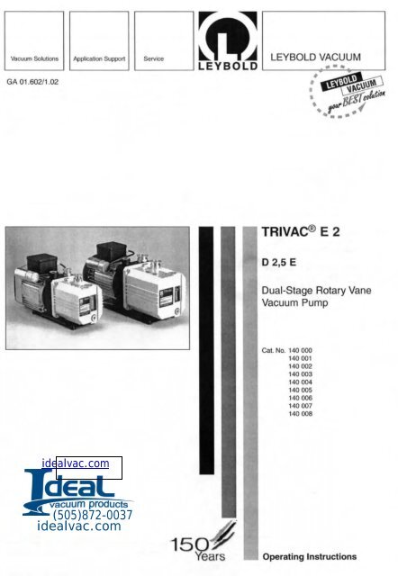
TRIVAC® E 2<br />
D 2,5 E<br />
Dual-Stage Rotary Vane<br />
<strong>Vacuum</strong> Pump<br />
Cat. No. 140 000<br />
140001<br />
140002<br />
140003<br />
140004<br />
140005<br />
140006<br />
140007<br />
140008<br />
Operating Instructions
Contents<br />
Contents<br />
Page<br />
IMPORTANT SAFETY CONSIDERATIONS . . 4<br />
1 Description • ...•.. ... ..... . ... . . . .... 6<br />
1.1 Principle of Operation ................... 6<br />
1.2 Supplied Equipment .................... 8<br />
1.2.1 Notes on the Oil and how to Order ......... 8<br />
1.3 Accessories .......................... 8<br />
1.4 Technical Data ........................ 9<br />
1.4.1 Motor Dependent Data .......... •• ...... 9<br />
2 Operation .. ... • .. .... .. .. ••• • •..... 12<br />
2.1 Installation ................ • • • • ...... 12<br />
2.2 Connection to the System ... . .•• ••• . .. . . 12<br />
2.3 Electrical Connection ... . . . ..•• • •• .... . 13<br />
2.3.1 Pumps with AC Motor ....... . . .. . . .... . 13<br />
2.4 Start-Up ........................... . 13<br />
<strong>2.5</strong> Operation ................ .. .... . . .. . 14<br />
<strong>2.5</strong>.1 Pumping of Non-Condensable Gases<br />
and Vapours .............. . ...... .. .. 14<br />
<strong>2.5</strong>.2 Pumping of Condensable Gases<br />
and Vapours ..................... . ... 14<br />
<strong>2.5</strong>.3 Operating Tem perature ................. 14<br />
2.6 Shut Down I Shelving ... ... ..... . • ..... 16<br />
2.6.1 Shut Down through Monitoring<br />
Components ......................... 16<br />
2.6.2 Failure of the Control System or<br />
the Mains Power . . . . .. .. . . .......... . 16<br />
2<br />
3<br />
3.1<br />
3.1.1<br />
3.2<br />
3.2.1<br />
3.3<br />
3.4<br />
3.5<br />
3.6<br />
3.7<br />
3.8<br />
4<br />
5<br />
5.1<br />
5.2<br />
6<br />
Checking I Maintenance . ... ••• • • • .... . 17<br />
Checking the Oil Level ...... . . . .... . . .. 17<br />
Oil Check . . . .... .. ....... ..... . .. 17<br />
Oil Change .................... . . .... 18<br />
Disposal of Used Pum p Materials ..... . . . . 18<br />
Cleaning the Dirt Trap .................. 19<br />
Removing and Inserting the<br />
Internal Demister ..................... 19<br />
Disassembly and Assembly of the<br />
Electric Motor . ....................... 20<br />
Full Maintenance ..................... 21<br />
<strong>Leybold</strong> Service ...................... 21<br />
Shelving . ... . .... . .......... . ....... 21<br />
Maintenance Plan ........ •• . . .••• • .•. 22<br />
Maintenance Kits and Repair Sets ••••• •. 24<br />
Ordering Information for the Maintenance Kits<br />
and the Repair Sets ...... . . . ....... . . . 28<br />
Ordering Information for the Special Tools ... 28<br />
Troubleshooting .. . . . .... .. ....... • .. 29<br />
EC - Declaration of Conformity ..•.. . . .. 30<br />
We reserve the right to modify the design and the<br />
specified data. The illustrations are not binding.<br />
GA 01.60211.02 . 03101
Warning' Before operating the TRIVAC E with atmospheric gas ballast (optional) check first compatibility with the<br />
pumped media so as to avoid hazardous conditions during operation right from the start.<br />
• Before commissioning the TRIVAC E. make sure thaI the media which are to be pumped are compatible<br />
with each other so as to avoid hazardous situations.<br />
All relevant safely standards and regulations must be observed.<br />
• 1t is recommended to always operate the TRIVAC E with a suitable exhaust line which is properly<br />
connected. It must slope down and away from the pump.<br />
• When moving the TRIVAC E always use the allowed means.<br />
A lifting eye is provided as standard on the pump.<br />
Caution Failure to observe the following precautions could result In damage to the pump:<br />
Note<br />
• Do not allow the ingestion of small objects (screws, nuts, washers, pieces of wire, etc.)<br />
through the inlet port. Always use the screen which is supplied with every pump.<br />
• Do not use the pump for applications that produce abrasive or adhesive powders or<br />
condensable vapours that can leave adhesive or high viscosity deposits. Please contact <strong>Leybold</strong> Sates<br />
Of Service to select a suitable separator. Also pease contact <strong>Leybold</strong> Sales or Service when planning<br />
to pump vapours other than water vapour.<br />
• This pump is suited for pumping water vapour within the specified water vapour tolerance limits.<br />
• Avoid vapours that can condense into liquids upon compression inside the pump, if these substances<br />
exceed the vapour tolerance of the pump (> 25 mbar for water vapour).<br />
• Before pumping vapours, the TRIVAC E should have attained its operating temperature, and the gas<br />
ballast should be set to position I • III (position 0 = closed, position 3 = max. water vapour tolerance,<br />
30 mbar).<br />
The pump will have attained its operating temperature about 30 minutes after starting the pump. During<br />
this time the pump should be separated from the process, by a valve in the intake line, for example.<br />
• In the case of wet processes we recommend the installation of liquid separators upstream and down·<br />
stream of the pump as well as the use of the gas ballast.<br />
• The exhaust line should be laid so that it slopes down and away from the pump so as to prevent con·<br />
densate from backstreaming into the pump. For this preferably use the flange on the side of the motor.<br />
• The entry of particles and fluids must be avoided under all circumstances.<br />
• Reactive or aggressive substances in the pump chamber may impair the operating oil or modify it.<br />
In addition, such substances may be incompatible with the materials of the pump (Viton, grey cast iron,<br />
aluminium, steel, resins, glass etc.).<br />
• Corrosion, deposits and cracking of oil within the pump are not allowed.<br />
This Information will help the operator to obtain the best performance from the equipment:<br />
• Normal amounts of humidity within the range of the pump's vapour tolerance will not significantly affect<br />
pump performance when the gas ballast is active. Preferably use the exhaust flange located on the side<br />
of the motor.<br />
GA 01 .602/1 .02·03101 5
Description<br />
Key to Fig. 1<br />
1 Intake pori<br />
2 Oil drain<br />
3 Oil level indicator<br />
4 Name plale<br />
5 Oillill<br />
6 Exhausl pori 7<br />
7 Gas ballast valve<br />
8 Mains power connection<br />
6<br />
Fig. 1 TRIVAC 0 2,5 E rotary Villle pump<br />
1 Description<br />
The TRIVAC 0 2,5 E are dual stage oil sealed rotary<br />
vane vacuum pumps.<br />
The number in the designation of the pump indicates the<br />
pumping speed of this pump in m 3 . h· l .<br />
These pumps are capable of pumping gases and<br />
vapours out of vessels and vacuum systems down into<br />
the fine vacuum pressure range. The standard pumps<br />
are not designed to handle oxygen at concentrations<br />
exceeding the concentration of oxygen in the atmosphere.<br />
Moreover, these pumps are not suited for pumping of<br />
hazardous gases or extremely aggressive or corrosive<br />
media.<br />
The drive motor of the TRIVAC 0 2,5 E is screwed directly<br />
to the bearing piece. The shah of the pump and the<br />
shaft of the motor are linked by a coupling piece. The<br />
bearings in the inner pump body are force-lubricated sliding<br />
bearings.<br />
The oil level glass for viewing the minimum/maximum oil<br />
level and the oil drain plug as well as the name plate are<br />
located on the front of the pump.<br />
The connection components, the gas ballast knob and<br />
the oil fill plug are located on the top of the pump.<br />
6<br />
5<br />
3<br />
2<br />
1. 1 Principle of Operation<br />
The rotor (2/6) which is eccentrically arranged in the<br />
pump housing (pump chamber) has two radially sliding<br />
vanes (2/7 and 2/9) which divide the pump chamber of<br />
the pump into several chambers.<br />
The volume of each chamber changes periodically with<br />
each turn of the rotor so that the gas at the intake port<br />
(1 / 1) is sucked in. The gas enters the pump chamber,<br />
and after the admission aperture has been sealed off by<br />
the vane, the gas is compressed and moved on.<br />
The compressed gas is ejected from the pump chamber<br />
through the exhaust valve. Oil which is entrained in the<br />
gas is roughly separated by an internal demister and at<br />
the same time any mechanical contaminations are also<br />
removed from the oil, The gas exits the pump through the<br />
exhaust port.<br />
Oil injected into the pump chamber serves the purpose<br />
of sealing and lubrication. The knocking noise (oil slap)<br />
which normally occurs when the pump approaches its<br />
ultimate pressure is avoided by injecting a small amount<br />
of air into the oil so that a silencing effect is attained.<br />
GA 0 1.60211.02 - 03J01
Key to FIg. 2<br />
1 Gas ballast valve<br />
2 Gas ballast inlet<br />
3 Tandem valve<br />
(vacuum protection)<br />
4 Intake pelft<br />
5 Oilleed (oil pump)<br />
6 Rotor<br />
7 Vane (HV)<br />
8 High vacuum stage<br />
(pump chamber)<br />
9 Vane (FV)<br />
10 Forevacuum stage<br />
(pump chamber)<br />
11 NOtHeturn valve<br />
12 Diaphragm valve<br />
13 Exhaust valve<br />
14 Bypass vatve<br />
I 5 Exhaust port<br />
Fig. 2 Sectional view Ihroogh a TRIVAC D 2,5 E pump<br />
By opening the gas ballast valve (211, optional) it is possible<br />
to admit a controlled quantity of air (gas ballast) into<br />
the pump chamber while the compression process is in<br />
progress. The gas ballast will preven't the condensation<br />
of vapours within the pump up to the extent of the vapour<br />
tolerance levels as stated in the specifications for the<br />
pump (these data refer to water vapour).<br />
A special lubrication system with forced lubrication of the<br />
sliding bearings has been developed to enable operation<br />
of the pump at intake pressures up to 1000 mbar.<br />
An oil pump supplies the oil from the oil reservoir into a<br />
high pressure oil system which in turn supplies all bearings.<br />
From here the oil enters the pump chamber of the<br />
vacuum pump.<br />
The oil pump is located in bearing piece of the high vacuum<br />
stage. Separation of oil and gas in the pump involves<br />
two stages. First an internal demister which is arranged<br />
ahead of the exhaust valve ensures the creation of larger<br />
droplets.<br />
Next these are returned back to the oil reservoir via a<br />
separation panel. This ensures a minimal loss of oil.<br />
GA 01.602/1 .02 . 03101<br />
11<br />
2<br />
3<br />
Description<br />
This and the combination with the large usable oil reser·<br />
voir, results in long intervals between the oil exchanges,<br />
even at high intake pressures.<br />
The gas ballast valve (GB) is opened or closed by turning<br />
it (positions 0, 1, 2, 3).<br />
Available as an option is a gas ballast valve having a<br />
knurled screw (see Fig. 11 on page 26). When fully<br />
opening this valve, the resulting gas flow will correspond<br />
to that of valve position 3 in the following Table.<br />
GB position Explanation<br />
o no gas ballast<br />
maximum ultimate pressure<br />
1 for cleaning the pump's oil at a good ulti·<br />
mate pressure and low oil consumption<br />
2 good water vapour tolerance·<br />
without producing excessive noise<br />
3 maximum water vapour tolerance in<br />
accordance with the technical data on<br />
page 6.<br />
5<br />
7
Operation<br />
2 Operation<br />
2.1 Installation<br />
The TRIVAC 0 2,5 E can be placed freely on a flat and<br />
horizontal surface.<br />
The rubber elements under the pump's base prevent the<br />
pump from slipping. If the pump is to be permanently<br />
attached, this may be done by making use of the holes<br />
in the rubber elements and a threaded bolt or similar.<br />
Caution The inclination of the pump (without additional<br />
fixing means) and with possibly attached<br />
standard accessories must not<br />
exceed an angle of 10° from the vertical<br />
axis.<br />
The rubber elements act as vibration absorbers.<br />
For this reason they must not be compressed<br />
by the screws. When installing the<br />
pump you must ensure accessibility of all<br />
connections and controls.<br />
Select a place for the pump which ensures a sufficient air<br />
circulation for cooling the pump (keep front and rear<br />
sides unobstructed).<br />
The ambient temperature around the pump should not<br />
exceed 50 °C (in the case of USA and Japan motors<br />
40 0c) and not drop below 10 °C (see Section <strong>2.5</strong>.3).<br />
If required the crane eye or the handle may be removed.<br />
Caution The oil filting has been included separately.<br />
Before operating the pump you must fill in<br />
the correct quantity of oil (see Section 3.2).<br />
12<br />
2.2 Connection to the<br />
System<br />
Before connecting the pump, the shipping seals on the<br />
connection flanges (511 and 512) must be removed.<br />
If residues of adhesives are present on the connecting<br />
flanges you must remove these using a suitable solvent<br />
like alcohol, for example.<br />
Insert the dirt sieve (518) with the O-ring.<br />
The intake and exhaust lines are filted with standard<br />
small flanges. The connection flanges must be clean and<br />
undamaged.<br />
The intake line and the exhaust line must be connected<br />
using corrugated pipes or vacuum hoses so that no<br />
mechanical forces can be transferred to the pump.<br />
The intake line must be clean. Any deposits in the intake<br />
line will tend to degas and impair the attainable vacuum<br />
pressures.<br />
The cross section of the intake and exhaust line must at<br />
least be of the same diameter as that of the pump<br />
connections.<br />
An intake line which is too small in diameter will throttle<br />
the pumping speed.<br />
An exhaust line which is too small in diameter can result<br />
in the formation of overpressures within the pump. Possible<br />
consequences are damaged shaft seals and possibly<br />
also an oil leak.<br />
The pressure in the oil box must not exceed 1.5 bar<br />
(abs.)<br />
When pumping vapours we strongly recommend the<br />
installation of a condensate separator on the suction<br />
side and also on the exhaust side.<br />
The exhaust line must be laid so that it slopes down and<br />
away from pump (lower than the pump) to prevent any<br />
condensate from flowing back into the pump. If a sloping<br />
line can not be installed, a separator must be fitted.<br />
When the oil mist is to be removed from the exhaust gas<br />
flow we recommend the installation of an exhaust filter.<br />
When pumping inert gases the pump's gas ballast inlet<br />
can directly be connected to the system by an adaptor<br />
(for this the gas ballast knob must be removed).<br />
Intake and exhaust port are of the screwed type and can<br />
be replaced by direct connection to the system.<br />
GA 01 .60211 .02 - 00101
Operation<br />
<strong>2.5</strong> Operation<br />
These pumps are capable of pumping gases and<br />
vapours. Vapours can only be pumped provided the gas<br />
ballast valve (optional) is open and provided the pump<br />
has attained its operating temperature.<br />
The maximum vapour tolerance is attained when the gas<br />
ballast valve (Sn) is set to position 3.<br />
<strong>2.5</strong>.1 Pumping of Non-Condensable Gases<br />
andVapours<br />
In the presence of excess quantities of permanent gases<br />
the pump may be operated without gas ballast. provided<br />
the saturation vapour pressure at the operating temperature<br />
is not exceeded during compression.<br />
If the composition of the gases which are to be pumped<br />
is not known and if the possibility of condensation within<br />
the pump can not be excluded, we recommend operation<br />
of the pump with the gas ballast valve open (in accordance<br />
with Section <strong>2.5</strong>.2).<br />
<strong>2.5</strong>.2 Pumping of Condensable Gases<br />
andVapours<br />
With the gas ballast valve (option) open and when the<br />
pump is running at its operating temperature, pure water<br />
vapour can be pumped up to the extent stated in the<br />
technical data for the pump (position 3 of the gas ballast<br />
valve). When the vapour pressure increases above the<br />
permissible level, the vapour will condense in the oil of<br />
the pump.<br />
When pumping vapours make sure that the gas ballast<br />
valve is open and that the pump has been running for at<br />
least 30 minutes with the intake line closed and with gas<br />
ballast.<br />
14<br />
Caution It will be possible to pump vapours up to the<br />
permissible limit only after the pump has<br />
reached its operating temperature.<br />
During the pumping process vapours may<br />
dissolve in the oil of the pump. This impairs<br />
the properties of the oil and there is the risk<br />
of corrosion within the pump. For this rea·<br />
son th e pump must not be switched off<br />
immediately after termination of the pro·<br />
cess. The pump must remain on with the<br />
gas ballast vatve open and the intake line<br />
sealed until all vapours which were dissolved<br />
in the oil have been removed.<br />
We strongly recommend that the TRIVAC<br />
o 2,5 E pumps be left running for about 30<br />
minutes after termination of the process.<br />
In the case of cyclic or repetitive processes the TRIVAC<br />
o 2,S E should not be switched off during the breaks between<br />
the individual work phases (low energy require·<br />
ment when running at ultimate pressure). The gas ballast<br />
valve should be opened and the inlake line should be<br />
sealed (th rough a valve, if possible).<br />
When all vapours have been pumped from a process<br />
(drying, for example) the gas ballast valve can be closed<br />
to improve the attainable ultimate pressure.<br />
<strong>2.5</strong>.3 Operating Temperature<br />
Proper operation of the TRIVAC 0 2,S E is ensured at<br />
am bient temperatures between 10 °C and 50 °C, with the<br />
exception of the pump models for the USA and Japan<br />
where a range of 10 °e to 40 °e applies.<br />
When using SHC 224 Arctic oil. the pump will reliably run<br />
up even at a temperature of 5 °e.<br />
When the pump is warm , the temperature at the surface<br />
of the oil box may rise to between 40 °e and 80 °e.<br />
depending on the load on the pump.<br />
m<br />
Warning TRI VAC E pumps may attain surface tem·<br />
A. peratures of over 80 °e .<br />
There is the danger of receiving burns.<br />
GA 01 .60211.02 · 00101
Operation<br />
2.6 Shut Down /<br />
Shelving<br />
During normal use of the TRIVAC D 2,5 E it will be sufficient<br />
to electrically switch off the pump. Further measures<br />
are not required.<br />
After having pumped condensable media, let the pump<br />
run for some time with the gas ballast valve open and the<br />
intake line blocked (see Section <strong>2.5</strong>.2).<br />
When pumping aggressive or corrosive media and also<br />
in the case of long process interruptions (overnight, for<br />
example) we recommend that you let the pump run with<br />
the intake line sealed and with the gas ballast switched<br />
on.<br />
This helps to prevent the occurrence of standstill corrosion.<br />
If the pump is to be switched off for a longer period of<br />
time after it has been pumping aggressive or corrosive<br />
media or if the pump is to be shelved, proceed as<br />
follows:<br />
Warning When hazardous substances have been<br />
&<br />
pumped ensure that the appropriate safety<br />
, precautions are observed.<br />
• For more information please contact our<br />
technical sales department.<br />
Seal off the intake port. The use of special conservation<br />
or anti-corrosion oils is not required.<br />
2.6.1 Shut Down through Monitoring<br />
Components<br />
Warning When the pump has been switched off due<br />
&<br />
to overheating sensed by the motor coil pro-<br />
,<br />
tector (single phase pumps only), the pump<br />
must only be started manually after the<br />
• pump has cooled down to the ambient temperature<br />
and after having removed the<br />
cause first.<br />
16<br />
2.6.2 Failure of the Control System<br />
or the Mains Power<br />
Warning In order to prevent the pump from running<br />
up unexpectedly after a mains power fail<br />
&<br />
ure, the pump must be integrated in the<br />
, control system in such a way that the pump<br />
• can only be switched on again manually.<br />
This applies equally to emergency cut-out<br />
arrangements.<br />
GA 01 .602J1 .02 - 03101
Key to Fig. 7<br />
1 Oii drain plug<br />
2 Oil 00)(<br />
3 He)(. socket SCfew (4)(j<br />
4 Oil fill plug<br />
5 Spring 7-----'-<br />
6 Guide panel<br />
7 Ho k:fing frame for the internal demister<br />
8 tntemal demister<br />
9 Dirt trap with Q.ring<br />
6-----<br />
10 Gasket lor the oil 00)(<br />
11 Enlarged detail of the gasket lor 5-----,<br />
the oil box<br />
Rg. 7 Removing and inserting the internal demister<br />
3.3 Cleaning the Dirt Trap<br />
9 - _ __ -..;<br />
B----,<br />
Maintenance Kits and Repair Sets<br />
5 Maintenance Kits and Repair Sets<br />
The maintenance and repair kits have been so arranged<br />
that the spare and exchange parts they contain cover<br />
any servicing work which might be required.<br />
Each set comes with brief in structions in which the<br />
necessary work is detailed. This very much simplifies the<br />
servicing or repair work.<br />
Given In the following Is a brief description of the<br />
Individual kits and how to use these.<br />
Maintenance Kit 1<br />
This kit is recommended for maintenance after an operating<br />
period of one year. It contains the gaskets for the<br />
oil box, the internal demister which separates the oil from<br />
the gas (for contents see page 25, Fig. 9).<br />
Repair Kit 1<br />
This kit is used for the seal on the side of the motor. It<br />
contains the gaskets for the side of the motor, the shaft<br />
sealing ring as well as the following wearing parts: coupling<br />
sleeves and compression spring for the oil pump<br />
(for contents see page 25, Fig. 10).<br />
Repair Kit 2<br />
This set will only be required in those cases where the<br />
pump is not capable of attaining its ultimate pressure.<br />
This kit contains the valves, the internal demister which<br />
separates the oil from the gas as well as the gaskets for<br />
the oil box (for contents see page 26, Fig. 11).<br />
Maintenance Kit 2 1 Repair Kit 3<br />
These kits are identical. They contain all wearing parts,<br />
all gaskets and the internal demister which separates the<br />
oil from the gas.<br />
They are used as follows:<br />
1. Maintenance after three years of operation<br />
2. Complete repair<br />
(for contents see pages 25. 26 and 27. F9. 10. 11 and t 2).<br />
24<br />
GA 01.60211.02 - 03r01
Maintenance Kits and Repair Sets<br />
5.1 Ordering Information for the Maintenance Kits<br />
and the Repair Sets<br />
TRIVAC 02,5 E 2<br />
Maintenance Kit 200 40 022<br />
Maintenance Kit 1 E 100000 347<br />
Repair-Set 1 E 100 000 351<br />
Repair-Set 2 200 40 024<br />
Repair-Set 3 E 100 000 347<br />
The use of the Maintenance Kits and the Repair Sets Is detailed In the Tables 4 - TroubieshooUng and 5 - Maintenance Plan.<br />
5.2 Ordering Information for the Special Tools<br />
TRIVAC 02,5 E 2<br />
Special tool for the lie rods 20002760<br />
28<br />
GA 01 .60211.02 - 03101
We - <strong>Leybold</strong> <strong>Vacuum</strong> GmbH - herewith declare that the<br />
products defined below meet the basic requirements<br />
regarding safety and health of the relevant EC directives<br />
by design, type and versions which are brought into circulation<br />
by us.<br />
In case of any product changes made without our approval,<br />
this declaration will be void.<br />
Designation of the products:<br />
Models:<br />
Product numbers:<br />
Cologne, January 15, 2<br />
Peter Kreuter, Busine<br />
Division Industrial<br />
30<br />
EC Declaration of Conformity<br />
Rotary vane pump<br />
dual stage<br />
TRIVAC E 2<br />
0 <strong>2.5</strong> E<br />
140000<br />
140001<br />
140002<br />
140003<br />
140004<br />
140005<br />
140006<br />
140007<br />
140 008<br />
The products conform to the following directives:<br />
• EC Directive on Machinery (98137/EG)<br />
• EC Directive on Low-Voltages (73123)+(93/68/EWG)<br />
• EC EMC Directive (89/336/EWG)<br />
(911263/EWG) + (92131IEWG) + (93/681EWG)<br />
Applied harmonised s tandards:<br />
• DIN EN 292 Part 1<br />
11 .91<br />
• DIN EN 292 Part 2 06.95<br />
• DIN EN 101 2 Part 2 07.96<br />
• DIN EN 60 204 Part 1 11 .98<br />
.. DIN EN 50 081 • Part 1 03.93<br />
.. DIN EN 50081 . Part 2 03.94<br />
• DIN EN 50 082 • Part 1 11.97<br />
• DIN EN 50 082 - Part 2 02.96<br />
Applied national s tandards and technical<br />
specifications:<br />
.. DIN 31 001 April 1983<br />
Cologne, January 15, 2001<br />
,;;<br />
Or. Bahnen, Head of R&D LPV<br />
Division Induslrial<br />
GA 01 .602J1 .02· 03101


