swimming pool heat pump installation and user guide - BRILIX.com
swimming pool heat pump installation and user guide - BRILIX.com
swimming pool heat pump installation and user guide - BRILIX.com

Create successful ePaper yourself
Turn your PDF publications into a flip-book with our unique Google optimized e-Paper software.
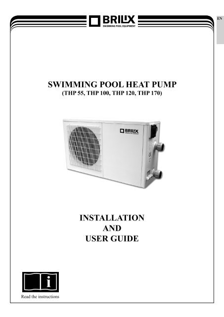
SWIMMING POOL HEAT PUMP<br />
(THP 55, THP 100, THP 120, THP 170)<br />
i<br />
Read the instructions<br />
INSTALLATION<br />
AND<br />
USER GUIDE<br />
EN
EN<br />
Contents<br />
I. Package content ..................................................... 3<br />
II. Performance <strong>and</strong> properties ................................... 3<br />
III. System design ........................................................ 4<br />
IV. Performance properties .......................................... 5<br />
V. Dimensions ............................................................ 6<br />
VI. Preparations for <strong>installation</strong> ................................... 6<br />
VII. Connection diagram ............................................. 10<br />
VIII. Operating the control unit.....................................11<br />
IX. Instructions........................................................... 15<br />
X. Checks ................................................................. 16<br />
XI. Problem solving .................................................. 17<br />
XII. Summary of error codes on the display................ 20<br />
XIII. Maintenance......................................................... 21<br />
Thank you for choosing our product <strong>and</strong> for your trust in our <strong>com</strong>pany. To ensure that you can fully enjoy<br />
the product, please read these instructions carefully <strong>and</strong> strictly follow the <strong>user</strong> <strong>guide</strong> so as not to damage the<br />
device <strong>and</strong> to avoid unnecessary injuries.<br />
2
I. Package content<br />
⑤<br />
①<br />
⑥<br />
① <strong>swimming</strong> <strong>pool</strong> <strong>heat</strong> <strong>pump</strong><br />
② instructions<br />
③ 2 pieces of fitting<br />
④ display cover for placement on the wall<br />
⑤ spare display cover<br />
⑥ 4 pieces of silent blocks<br />
⑦ connection cable for display<br />
⑧ 2 pieces of terminals fro condensate drain<br />
⑨ 4 pieces of fixing srews<br />
②<br />
II. Performance <strong>and</strong> properties<br />
High performance<br />
Our <strong>heat</strong> <strong>pump</strong>s are very efficient in transferring <strong>heat</strong> from air to water in the <strong>pool</strong>. They can provide savings<br />
of up to 80% in energy <strong>com</strong>pared to an electric <strong>heat</strong>er.<br />
Long life<br />
The <strong>heat</strong> exchanger is made from a PVC/titanium <strong>com</strong>posite pipe resistant to the long-term effects of <strong>pool</strong><br />
water.<br />
Simple operation <strong>and</strong> maintenance<br />
The device is easy to control: switch it on <strong>and</strong> set the required temperature of the water in the <strong>pool</strong>.<br />
The system incorporates a micro<strong>com</strong>puter control unit which allows all the operational parameters to be specified.<br />
The state of operation can be displayed on the control unit through an LED display.<br />
3<br />
⑦<br />
③<br />
⑧<br />
⑨<br />
④<br />
EN
EN<br />
III. System design<br />
hot air<br />
colder air depleted<br />
of energy<br />
<strong>com</strong>pressor<br />
ventilator<br />
evaporator<br />
(energy collector)<br />
<strong>swimming</strong> <strong>pool</strong><br />
condenser<br />
water <strong>heat</strong> exchanger<br />
capillary tube<br />
<strong>pump</strong><br />
<strong>swimming</strong> <strong>pool</strong> cleaner<br />
• Heat <strong>pump</strong>s make use of free <strong>heat</strong> from the sun by collecting <strong>and</strong> absorbing energy from the outside air.<br />
• This device contains a ventilator which draws the outside air in <strong>and</strong> makes it flow over the surface of<br />
the EVAPORATOR (energy collector). The liquid coolant in the EVAPORATOR pipeline absorbs the <strong>heat</strong><br />
from the outside air <strong>and</strong> the coolant vaporises.<br />
• The warm gas in the pipeline passes through the COMPRESSOR which gathers the <strong>heat</strong> <strong>and</strong> increases<br />
the temperature to generate very hot gas which then passes to the CONDENSER (water <strong>heat</strong> exchanger).<br />
This is where the <strong>heat</strong> exchange occurs - the hot gas transfers <strong>heat</strong> to the colder water from the <strong>pool</strong> which<br />
is circulating through the coil.<br />
• The <strong>pool</strong> water is <strong>heat</strong>ed <strong>and</strong> the hot gas is cooled when passing through the CONDENSER pipeline<br />
– it regains its liquid form <strong>and</strong>, after the passage through the CAPILLARY TUBE, the whole process<br />
re<strong>com</strong>mences.<br />
• The current technology used in the <strong>heat</strong> <strong>pump</strong> allows efficient use even at an outside air temperature of 7 to 10 ºC.<br />
For tropical <strong>and</strong> subtropical climates, this means that 26 to 32 ºC may be maintained in the <strong>pool</strong> under almost any<br />
conditions all year round. In northern countries, the <strong>heat</strong> <strong>pump</strong> considerably extends the <strong>swimming</strong> season.<br />
4
IV. Performance properties<br />
Performance properties of a monoblock-type <strong>heat</strong> <strong>pump</strong> for <strong>swimming</strong> <strong>pool</strong>s<br />
Code THP 55 THP 100 THP 120 THP 170<br />
Nominal <strong>heat</strong> output - at an outside<br />
temperature of 15°C<br />
W 5500 9900 11800 17300<br />
BTU 19000 34000 41300 59500<br />
C.O.P. ≥4,5 ≥5,1 ≥4,5 ≥4,7<br />
Heat input W 1240 1940 2650 3670<br />
Operating current for <strong>heat</strong>ing A 5,5 9,6 13,3 18<br />
Current supply V/phase/Hz 220-240/1/50<br />
Number of <strong>com</strong>pressors 1 1 1<br />
Compressor Rotary Scroll<br />
Number of ventilators 1 1 1 1<br />
Input of ventilators W 25 50 50 50<br />
Ventilator speed RPM 950 950 950 950<br />
Noise dB(A) 53 55 57 59<br />
Mains pipe mm 50 50 50 50<br />
Water flow m 3 /h 2-4 4-6 6-8 8-10<br />
Decrease in water pressure kpa 20 20 20 20<br />
Coolant (R407C) kg 0,8 1,3 1,3 2,1<br />
Net dimensions<br />
Packaged dimensions<br />
Weight<br />
L<br />
W mm<br />
360 370 370 470<br />
5<br />
935 1090 1090 1165<br />
H 550 615 615 685<br />
L<br />
1060 1140 1140 1195<br />
W mm<br />
380 400 400 485<br />
H 600 660 660 730<br />
net<br />
40 62 65 99<br />
kg<br />
gross 48 71 77 104<br />
1<br />
EN
EN<br />
V. Dimensions<br />
Dimensions of <strong>heat</strong> <strong>pump</strong>s (monoblock-type) for <strong>swimming</strong> <strong>pool</strong>s<br />
VI. Preparations for <strong>installation</strong><br />
Model<br />
THP 55 THP 100 THP 120<br />
Dimension<br />
L 1000 1090 1090<br />
W 360 370 370<br />
H 550 612 612<br />
A 330 340 340<br />
B 680 640 640<br />
E 81 84 84<br />
F 200 270 270<br />
Unit: mm<br />
Dimension<br />
Model<br />
6.1 Selection of the <strong>installation</strong> position<br />
• The <strong>heat</strong> <strong>pump</strong> has to be installed in a spacious <strong>and</strong> well ventilated place.<br />
• Its position has to guarantee adequate free space for the exhaust (the location of the air inlet is shown<br />
in the diagram on the next page).<br />
• The <strong>heat</strong> <strong>pump</strong> has to be situated close to a drain or vent so as to make water discharge easier.<br />
• The <strong>installation</strong> base or brace has to be firm enough to ensure smooth operation of the device.<br />
• Make sure the device, when installed, is situated vertically, without any inclination.<br />
• Do not install the device in places where there is contamination, corrosive gas or where dirt or fallen<br />
leaves accumulate.<br />
• The <strong>heat</strong> <strong>pump</strong> must not be installed in the vicinity of an inflammable or explosive environment or<br />
near things that are a <strong>com</strong>mon cause of fire.<br />
• Maintain the distances from obstacles as indicated with arrows in the picture below.<br />
6<br />
THP 170<br />
L 1165<br />
W 470<br />
H 685<br />
A 440<br />
B 760<br />
F 325<br />
G 81,5<br />
Unit: mm
air<br />
inlet<br />
min.<br />
1000 mm<br />
air<br />
inlet<br />
min. 1000 mm from above<br />
air<br />
outlet<br />
min. 2000 mm<br />
WARNING:<br />
• Do not put your h<strong>and</strong> or any object into the air outlet or ventilator, as this could damage the device <strong>and</strong><br />
cause an injury.<br />
• In the event of any abnormalities, switch off the device immediately <strong>and</strong> contact an expert technician.<br />
• If needed, you should place barriers next to the device to keep children away from the running <strong>heat</strong><br />
<strong>pump</strong>.<br />
7<br />
min. 1000 mm<br />
min.<br />
1000 mm<br />
Requirements for free space around the horizontal <strong>heat</strong> <strong>pump</strong><br />
EN
EN<br />
6.2 Fitting diagram<br />
input for<br />
power cable<br />
<strong>heat</strong> <strong>pump</strong><br />
output<br />
input<br />
discharge pipe<br />
for condensed water<br />
T<br />
o<br />
t<br />
h<br />
e<br />
s<br />
w<br />
i<br />
m<br />
m<br />
i<br />
n<br />
g<br />
p<br />
o<br />
o<br />
l<br />
discharge<br />
spout<br />
water treatment side joining valve<br />
<strong>swimming</strong> <strong>pool</strong><br />
water feed<br />
CIRCULATION<br />
Valve 1<br />
Valve 3<br />
Valve 2<br />
from to<br />
HEAT PUMP<br />
8<br />
water input<br />
Discharge connection<br />
water <strong>pump</strong><br />
F<br />
r<br />
o<br />
m<br />
t<br />
h<br />
e<br />
f<br />
i<br />
l<br />
t<br />
e<br />
r<br />
filter
6.3 Electrical connection<br />
IMPORTANT: The <strong>installation</strong> <strong>and</strong> connection of this device to the power supply can be provided only by<br />
authorized person according to order publication no. 50/1978 sb. Although the <strong>heat</strong> <strong>pump</strong> is electrically<br />
insulated from the rest of the unit, this fact only prevents the passage of electrical current to or from the water<br />
in the <strong>swimming</strong> <strong>pool</strong>. It is still necessary to earth the unit to protect yourself against short-circuit inside<br />
the unit. Ensure the appropriate earthing.To supply voltage please prepend circuit broker with current value<br />
according to type of <strong>heat</strong> <strong>pump</strong> you are connecting, <strong>and</strong> current protektor with residual current 0,03A.<br />
Before connecting the unit, check whether the electrical mains voltage corresponds to the voltage of the <strong>heat</strong><br />
<strong>pump</strong>.<br />
For horizontal models: remove the panel to the right of the ventilator aperture.<br />
Please connect the wires to terminal block marked as source power A second terminal is located next to<br />
this connector labelled „water <strong>pump</strong>“, which a filtration <strong>pump</strong> can be connected to (max. 5 A / 230 V). This<br />
connection allows you to control the operation of the filtration <strong>pump</strong> via the <strong>heat</strong> <strong>pump</strong>.<br />
Various possibilities: see table.<br />
Model Voltage (V) Circuit breaker (A) Nominal current (A)<br />
9<br />
Cable diameter (mm 2 )<br />
pro max. délku 15 m<br />
THP55 220-240 10 5,7 2 x 2,5 + 2,5<br />
THP100 220-240 16 9,7 2 x 2,5 + 2,5<br />
THP120 220-240 20 12,7 2 x 4,0 + 4,0<br />
THP170 220-240 32 17,2 2 x 6,0 + 4,0<br />
EN
EN<br />
VII. Connection diagram<br />
CONNECTION DIAGRAM FOR THE SWIMMING POOL THERMAL PUMP<br />
POWER SUPPLY<br />
Models: THP 55, THP 100, THP 120<br />
start<br />
relay<br />
four-way valve<br />
ventilator<br />
electric<br />
remote<br />
control<br />
electric<br />
remote<br />
control<br />
10<br />
coil temperature<br />
high pressure switch<br />
low pressure switch<br />
flow switch<br />
outside air temperature<br />
Models: THP 170<br />
<strong>pump</strong> electric <strong>heat</strong>er<br />
coil temperature<br />
high pressure switch<br />
low pressure switch<br />
flow switch<br />
outside air temperature<br />
temperature of in<strong>com</strong>ing water<br />
temperature of outgoing water<br />
CONNECTION DIAGRAM FOR THE SWIMMING POOL THERMAL PUMP<br />
POWER SUPPLY<br />
WATER<br />
PUMP<br />
WATER<br />
PUMP<br />
four-way valve<br />
ventilator<br />
<strong>pump</strong> electric <strong>heat</strong>er<br />
temperature of in<strong>com</strong>ing water<br />
temperature of outgoing water
VIII. Operating the control unit<br />
Preliminary steps before start-up<br />
A) Inspect the <strong>heat</strong> <strong>pump</strong><br />
• Visually check the device or the pipeline within the device to ensure that the device was not damaged<br />
during transport.<br />
• Check that the ventilator does not touch any other part of the device.<br />
B) Check the electric connections<br />
• Check that the electricity supply <strong>com</strong>plies with the technical data in this <strong>guide</strong> or on the device identification<br />
plate.<br />
• Check that the wiring is correctly <strong>and</strong> safely connected in accordance with the wiring diagram. An adequate<br />
earth connection is necessary to protect from electric shocks.<br />
8.1 Picture of the control unit<br />
A. On / off button.<br />
B. Mode selector – automatic, <strong>heat</strong>ing or cooling.<br />
There are indicator lights for the selected modes.<br />
or C. Buttons for changing the numbers displayed.<br />
D. Button for setting the switch-on time.<br />
E. Button for setting the switch-off time.<br />
F. Button for adjusting the time.<br />
8.2 How to activate the <strong>heat</strong> <strong>pump</strong><br />
When connected to a power supply, the control unit will show the time. This means the device is in<br />
st<strong>and</strong>by mode. Pushing the button will activate the <strong>heat</strong> <strong>pump</strong>. The control unit display will now show<br />
the temperature of the input water.<br />
St<strong>and</strong>by<br />
11<br />
Operation<br />
EN
EN<br />
NOTE: In order for the unit to be able to <strong>heat</strong> the <strong>swimming</strong> <strong>pool</strong> (or spa), the filtration <strong>pump</strong> must be in<br />
operation in order for water to be able to circulate via the <strong>heat</strong> <strong>pump</strong>. The <strong>heat</strong> <strong>pump</strong> will not start without<br />
circulation.<br />
After checking all connections, you should follow the steps as set out below:<br />
1. Switch on the filtration <strong>pump</strong>. Check whether any water is leaking out <strong>and</strong> check the flow to <strong>and</strong> from<br />
the <strong>swimming</strong> <strong>pool</strong>.<br />
2. Connect the power supply to the unit <strong>and</strong> then press the ON/OFF button on the electronic control panel.<br />
After a short time delay, the unit should start up.<br />
3. After the unit has been running for a few minutes, check whether the air <strong>com</strong>ing out of it is cooler.<br />
4. Check the functioning of the flow switch as follows: switch off the filtration <strong>pump</strong> when the unit<br />
is running. The unit should also automatically switch off.<br />
5. The whole unit <strong>and</strong> the filtration <strong>pump</strong> will operate for 24 hours a day until the required water temperature<br />
in the <strong>swimming</strong> <strong>pool</strong> is achieved. After the set temperature is achieved, the unit switches itself off.<br />
The unit then automatically starts (if the filtration <strong>pump</strong> is working) if the water temperature in<br />
the <strong>swimming</strong> <strong>pool</strong> drops by more than 1 °C below the set temperature.<br />
!!! It may take several days for the water to reach the required temperature depending on the initial<br />
water temperature in the <strong>swimming</strong> <strong>pool</strong> <strong>and</strong> the air temperature. You can shorten this time significantly<br />
by covering the <strong>swimming</strong> <strong>pool</strong>.<br />
Flow switch<br />
The unit is equipped with a flow switch, which switches on if sufficient amounts of water pass through<br />
the unit <strong>and</strong> switches off again if the water flow is too low (e.g. if the filtration <strong>pump</strong> is switched off). This<br />
system avoids only water found in the <strong>heat</strong> <strong>pump</strong> itself being <strong>heat</strong>ed.<br />
Condensation<br />
When <strong>heat</strong>ing the water in the <strong>swimming</strong> <strong>pool</strong> using the <strong>heat</strong> <strong>pump</strong>, the in<strong>com</strong>ing air is significantly cooled,<br />
which could cause condensation on the ribs of the evaporator. Condensation amounts may reach several<br />
litres per hour in the event of high atmospheric moisture. This condition is sometimes incorrectly regarded<br />
as leakage of water.<br />
12
8.3 How to change the mode<br />
Press the button to change the mode to automatic, <strong>heat</strong>ing or cooling. The appropriate indicator light<br />
will be illuminated on the right side of the control unit.<br />
8.4 How to check the settings <strong>and</strong> the current measured values<br />
In the st<strong>and</strong>by mode or operation mode, use the buttons or to find the parameter 0-A <strong>and</strong> the current<br />
measured values<br />
Parameter Meaning Scope Factory setting<br />
00 Required water temperature in cooling mode 8–28 °C 12 °C<br />
01 Required water temperature in <strong>heat</strong>ing mode 15–40 °C 40 °C<br />
02 Defrosting cycle 30–90 min. 45 min.<br />
03 Set temperature on the evaporator for start of defrosting –30–0 °C<br />
Parameter 1<br />
13<br />
–7 °C<br />
– not displayed<br />
04 Set temperature on the evaporator for end of defrosting 2–30 °C 13 °C<br />
05 Maximum duration of defrosting 1–15 min. 8 min.<br />
06 Number of <strong>com</strong>pressors in the system 1–2 1<br />
07 Restart after power failure 0–1 1 (ano)<br />
08<br />
09<br />
Type: only cooling 0/<br />
Heating <strong>and</strong> cooling 1/<br />
Heating <strong>and</strong> cooling + supplementary <strong>heat</strong>ing 2/<br />
Only <strong>heat</strong>ing 3/<br />
Various water <strong>pump</strong> operating modes:<br />
Water <strong>pump</strong> working constantly 0/<br />
Water <strong>pump</strong> working in harmony with the <strong>heat</strong> <strong>pump</strong> 1/<br />
0–3 1<br />
0–1 0<br />
A Required water temperature in automatic mode 8–40 ºC 28 ºC<br />
B Actual temperature of in<strong>com</strong>ing water -9 +90 ºC<br />
C Actual temperature of outgoing water -9 +90 ºC<br />
D Pipe water temperature in the system 1 -9 +90 ºC<br />
E Pipe water temperature in the system 1 (only for double system) -9 +90 ºC<br />
F Ambient temperature -9 +90 ºC<br />
IMPORTANT: The „–“ icon, which symbolises levels below 0 CANNOT be displayed here. The value „1–30“ represents<br />
„–1 °C“ to „–30 °C“. The default setting „7 °C“ actually represents „–7 °C“.<br />
Current<br />
measured<br />
value<br />
EN
EN<br />
8.5 How to tell the current status<br />
If the <strong>heat</strong> <strong>pump</strong> is in operation, press <strong>and</strong> to check the current status of the unit. You can check<br />
the temperature of the in<strong>com</strong>ing/outgoing water, the temperature of the condenser <strong>and</strong> the temperature of<br />
the outside air. Please be careful not to touch the controller for five seconds; the controller will return to<br />
the main interface, which displays the temperature of the in<strong>com</strong>ing <strong>and</strong> outgoing water.<br />
If the <strong>heat</strong> <strong>pump</strong> is in st<strong>and</strong>by mode, the controller will only show the temperature of the outside air.<br />
NOTES: St<strong>and</strong>by mode means that the unit is connected to the power supply but not in operation.<br />
Parameters 00–09 can ONLY be changed in st<strong>and</strong>by mode!<br />
8.6 How to adjust the parameter configurations<br />
1. Find the regime you want to change (AUTO, HEAT, or COOL) by pressing the MODE button in the st<strong>and</strong>by<br />
regime (a control light will lit next to the active mode)<br />
2. Press the button (arrows) <strong>and</strong> then press the button (arrows) once more to change the values of the mode<br />
next to which the control light lits (AUTO, HEAT, COOL)<br />
3. Should no button on the control unit be pressed within 5 seconds, the system will automatically save<br />
the data <strong>and</strong> the unit will return to st<strong>and</strong>-by regime.<br />
Advanced parameter control (the manufacturer does not re<strong>com</strong>mend adjusting these values)<br />
4. In order to adjust or check the remaining parameters (2-9 <strong>and</strong> B-F), press the MODE button after having<br />
executed instructions under section 2 above <strong>and</strong> then select the parameter you want to adjust by pressing<br />
the button (arrows).<br />
5. After selecting the parameter you want to adjust <strong>and</strong> pressing the MODE button once more, changes can<br />
be made to the parameter by pressing the button (arrows).<br />
6. Should no button on the control unit be pressed within 5 seconds, the system will automatically save<br />
the data <strong>and</strong> the unit will return to st<strong>and</strong>-by regime.<br />
Time delay<br />
The unit is fitted with a three-minute delay before starting up in order to protect the electrical <strong>com</strong>ponents<br />
<strong>and</strong> contacts. After this time delay has passed, the unit automatically restarts. Even a short power cut will<br />
activate the time delay <strong>and</strong> prevent the unit from being started immediately. A further power cut during this<br />
time delay will not have any effect on the three-minute countdown.<br />
8.7 How to set the clock<br />
1. In the st<strong>and</strong>by mode, press button . The hour digits will start flashing to show that they can be changed<br />
using buttons or .<br />
2. Again, press button . The minute digits will start flashing to show that they can be changed using<br />
buttons or .<br />
3. To confirm the time setting, press button .<br />
8.8 How to set the switch-on <strong>and</strong> switch-off time using the timer<br />
a) Press button to activate the timer switch-on time setting mode. The hour <strong>and</strong> minute digits will start<br />
flashing.<br />
b) Again, press button to activate clock setting. The hour digits will start flashing to show that they can<br />
be changed using buttons <strong>and</strong> .<br />
c) Press button to confirm the setting. The display will return to st<strong>and</strong>by mode. The green indicator light<br />
for the switch-on time of the timer will be illuminated.<br />
14
d) To set the switch-off time of the timer, take the same steps. Instead of button use button .<br />
The green indicator light for the switch-off time of the timer will be illuminated.<br />
NOTE: You can set both the switch-on <strong>and</strong> switch-off times of the timer, or only one.<br />
8.9 How to cancel / reset the timer function<br />
For activation, press button or . The appropriate indicator light will start flashing. To cancel / reset<br />
the timer function, press button .<br />
8.10 Lock / Unlock the keyboard<br />
When you have finished setting the parameters, pressing buttons or simultaneously for three seconds<br />
(until a beep is heard) will lock the keyboard. To unlock it, press these two buttons simultaneously for other<br />
three seconds.<br />
IX. Instructions<br />
9.1 Protection against high <strong>and</strong> low pressure in the coolant gas<br />
Protection against high pressure ensures that the <strong>heat</strong> <strong>pump</strong> is not damaged in the event of excessive gas<br />
pressure. Protection against low pressure sends a signal if the coolant gas is leaking from the pipes <strong>and</strong> the<br />
unit cannot be maintained in operation.<br />
9.2 Operating pressure<br />
Operating pressure <strong>and</strong> gas temperature are displayed by the built-in manometer. If the <strong>heat</strong> <strong>pump</strong> is operating<br />
correctly, the h<strong>and</strong>s of the manometer will be seen in the green zone. Pressure <strong>and</strong> gas are scanned in<br />
the pipes at the <strong>com</strong>pressor outlet before the <strong>heat</strong> exchanger.<br />
9.3 Protection of the <strong>com</strong>pressor against over<strong>heat</strong>ing<br />
This protection protects the <strong>com</strong>pressor against over<strong>heat</strong>ing.<br />
9.4 Automatic regulation of defrosting<br />
If the air is damp <strong>and</strong> cold, ice could form on the evaporator. If this is the case, a thin layer of ice will appear,<br />
which will continue to grow while the <strong>heat</strong> <strong>pump</strong> is operating. When the temperature of the evaporator gets<br />
too low, automatic regulation of defrosting will be activated, which will reverse the cycle of the <strong>heat</strong> <strong>pump</strong><br />
in such a way that hot gas will flow through the evaporator for a short period of time in order to defrost it.<br />
9.5 Temperature difference between in<strong>com</strong>ing <strong>and</strong> outgoing water<br />
Under normal operation of the <strong>heat</strong> <strong>pump</strong>, the temperature difference between in<strong>com</strong>ing <strong>and</strong> outgoing water<br />
will be approximately 1–2 °C. If the time switch is not working <strong>and</strong> water stops circulating, the temperature<br />
probe monitoring outgoing water will always detect increased temperature. As soon as the temperature difference<br />
between the in<strong>com</strong>ing <strong>and</strong> outgoing water exceeds 13 °C, the <strong>heat</strong> <strong>pump</strong> will automatically switch off.<br />
9.6 Shut-off if the temperature is low<br />
If during cooling, the temperature of the outgoing water reaches 5 °C or drops below this temperature, the <strong>heat</strong><br />
<strong>pump</strong> will switch itself off until the water temperature again increases to 7 °C or exceeds this temperature.<br />
15<br />
EN
EN<br />
9.7 Chemical <strong>com</strong>position of water in the <strong>swimming</strong> <strong>pool</strong><br />
Special attention should be given to the chemical balance of water in the <strong>swimming</strong> <strong>pool</strong>. The water values<br />
should always remain within the following limits:<br />
pH 7,2-7,6<br />
active chlorine (mg/l) 0,1-0,6<br />
IMPORTANT: Non-adherence to these limits will result in loss of validity of the guarantee.<br />
NOTE: Exceeding one or more of these limits may damage the <strong>heat</strong> <strong>pump</strong> beyond repair. Always fit equipment<br />
for water treatment behind the discharge pipe from the <strong>heat</strong> <strong>pump</strong>, especially if chemicals are added to the water<br />
automatically. A backflow valve should also be fitted, specifically between the <strong>heat</strong> <strong>pump</strong> discharge pipe <strong>and</strong> this<br />
equipment in order to prevent flow of substances back into the <strong>heat</strong> <strong>pump</strong> if the filtration <strong>pump</strong> stops.<br />
9.8 Preparation of the <strong>heat</strong> <strong>pump</strong> for winter<br />
IMPORTANT: If effective <strong>and</strong> essential measures to prepare the <strong>heat</strong> <strong>pump</strong> for winter are not taken, the <strong>heat</strong><br />
<strong>pump</strong> could be damaged, which will result in loss of validity of the guarantee.<br />
The <strong>heat</strong> <strong>pump</strong>, filtration <strong>pump</strong>, filter <strong>and</strong> pipes must be protected in places where the temperature could fall<br />
below the freezing point. Remove all water from the <strong>heat</strong> <strong>pump</strong> as follows:<br />
1. Disconnect the power supply to the <strong>heat</strong> <strong>pump</strong>.<br />
2. Close the water inlet to the <strong>heat</strong> <strong>pump</strong>: <strong>com</strong>pletely close valves 2 <strong>and</strong> 3 in the circulation system.<br />
3. Disconnect the connection parts of the <strong>heat</strong> <strong>pump</strong> for intake <strong>and</strong> outlet of water <strong>and</strong> allow the water to<br />
drain from the unit.<br />
4. Loosely reconnect the connection parts for water intake <strong>and</strong> outlet to/from the <strong>heat</strong> <strong>pump</strong> in order to avoid<br />
any pollutants getting into the pipes.<br />
9.9 Starting up the <strong>pump</strong> again after winter<br />
If you cleaned out the <strong>heat</strong> <strong>pump</strong> in preparation for winter, you should take the following steps in the spring<br />
before starting the unit up:<br />
1. First check whether there are any pollutants in the pipes <strong>and</strong> whether there are any structural problems.<br />
2. Check whether the connection parts for water intake <strong>and</strong> outlet are properly secured to the <strong>heat</strong> <strong>pump</strong>.<br />
3. Start up the filtration <strong>pump</strong> in order to start the flow of water to the <strong>heat</strong> <strong>pump</strong>. Restart circulation.<br />
4. Reconnect the power supply to the <strong>heat</strong> <strong>pump</strong> <strong>and</strong> switch it on.<br />
X. Checks<br />
Our <strong>heat</strong> <strong>pump</strong> was developed <strong>and</strong> assembled in such a way as to last if fitted correctly <strong>and</strong> can function under<br />
normal conditions. If you want your <strong>heat</strong> <strong>pump</strong> to function for many years to <strong>com</strong>e without interruption,<br />
safely <strong>and</strong> effectively, regular checks are important.<br />
1. Ensure easy access to the service panel.<br />
2. Keep the area around the <strong>heat</strong> <strong>pump</strong> clean free of any organic waste.<br />
3. Remove plants near the <strong>heat</strong> <strong>pump</strong> to ensure enough free space around it.<br />
4. Remove any water sprinklers from the vicinity of the <strong>heat</strong> <strong>pump</strong>. They could damage the <strong>pump</strong>.<br />
5. Avoid rain water trickling from the roof directly onto the <strong>heat</strong> <strong>pump</strong>. Fit the appropriate rainwater<br />
drainage.<br />
16
6. Do not use the <strong>heat</strong> <strong>pump</strong> if it was flooded. Immediately contact a qualified specialist to check the <strong>pump</strong><br />
<strong>and</strong> repair it if necessary.<br />
Condensation may occur when the <strong>heat</strong> <strong>pump</strong> is running. This condensation may drain away from the aperture in<br />
the bottom of the unit. The amount of condensed water increases if atmospheric moisture is high. Remove any pollutants,<br />
which could prevent drainage of condensation.<br />
When the unit is running, 10 to 20 litres of condensed water may be produced. If more water than this is created, stop<br />
the <strong>heat</strong> <strong>pump</strong> <strong>and</strong> wait for one hour before checking for leaks in the pipes.<br />
IMPORTANT: A quick method of checking whether water flowing from the condensation pipe really is condensed,<br />
is to stop the unit <strong>and</strong> leave the <strong>swimming</strong> <strong>pool</strong> <strong>pump</strong> in operation. If water stops flowing from the condensation<br />
pipe, it is condensed. AN EVEN FASTER METHOD is TESTING FOR THE PRESENCE OF CHLORINE IN THE<br />
water <strong>com</strong>ing from the pipe. If no chlorine is found, the water being drained is the result of condensation.<br />
Also make sure that the air intake <strong>and</strong> outlet is clear. Prevent waste air from immediately returning to<br />
the unit via the intake.<br />
XI. Problem solving<br />
Incorrect fitting could lead to electrical discharge, which could lead to fatal or serious injury to <strong>user</strong>s of<br />
the <strong>swimming</strong> <strong>pool</strong> as a result of electric shock <strong>and</strong> could also cause damage to property.<br />
DO NOT ATTEMPT to change the internal configuration of the <strong>heat</strong> <strong>pump</strong>.<br />
1. In order to avoid injury, make sure that your h<strong>and</strong>s <strong>and</strong> hair do not <strong>com</strong>e into the vicinity of the ventilator<br />
blades.<br />
2. If you are not familiar with filtration systems <strong>and</strong> the <strong>heat</strong> <strong>pump</strong> in your <strong>swimming</strong> <strong>pool</strong>:<br />
a. Do not attempt to set or adjust equipment without advice from your dealer or a specialist supplier<br />
of treatment <strong>and</strong> air-conditioning equipment.<br />
b. Before using the equipment for the first time, adjusting or setting the unit, read the whole <strong>installation</strong><br />
<strong>and</strong> operating instructions.<br />
NOTE: Before <strong>com</strong>mencing maintenance or repairs, disconnect the power supply.Note that only authorized<br />
person can provide maintanence of any electric device.<br />
IMPORTANT: If a defect cannot be resolved immediately, in order to analyse the problem itself, it will be<br />
necessary to know details of the message (error code), which is shown on the display of the controller, as<br />
well as the values for the settings (parameters 0–A for the LED display) <strong>and</strong> for the status of the <strong>heat</strong> <strong>pump</strong><br />
(ambient air temperature, temperature of the in<strong>com</strong>ing/outgoing water <strong>and</strong> coil temperature) directly before<br />
the defect or, if possible, directly after it.<br />
The following pages contain a summary of various types of problems, which may occur, together with<br />
instructions for their resolution.<br />
17<br />
EN
EN<br />
Problem Symptoms Possible cause Solution<br />
The <strong>heat</strong> <strong>pump</strong> is not working. The display does not light up<br />
<strong>and</strong> the ventilator/<strong>com</strong>pressor<br />
is not emitting any sound.<br />
The <strong>heat</strong> <strong>pump</strong> is working normally,<br />
but there<br />
is no / insufficient <strong>heat</strong>ing.<br />
The <strong>heat</strong> <strong>pump</strong> is working normally,<br />
but the water is being cooled instead<br />
of <strong>heat</strong>ed.<br />
The display is showing<br />
the temperature,<br />
but no error codes.<br />
The display shows<br />
the temperature,<br />
but no error codes.<br />
18<br />
No power supply. Check the power supply (cabling,<br />
fuses....).<br />
1. Insufficient capacity of<br />
the <strong>heat</strong> <strong>pump</strong> in relation<br />
to the size of the <strong>swimming</strong><br />
<strong>pool</strong>.<br />
2. The <strong>com</strong>pressor is working, but<br />
the ventilator is not.<br />
3. The ventilator is working,<br />
but the <strong>com</strong>pressor is not.<br />
4. The <strong>heat</strong> <strong>pump</strong> was not<br />
positioned in the optimum<br />
position.<br />
1. Install a larger model or<br />
additional <strong>heat</strong> <strong>pump</strong>.<br />
Cover the <strong>swimming</strong><br />
<strong>pool</strong> in order to limit<br />
<strong>heat</strong> loss.<br />
2. Check the electrical<br />
connection to the ventilator.<br />
If necessary, replace<br />
the condenser or ventilator<br />
motor.<br />
3. Check the electrical<br />
connection<br />
to the <strong>com</strong>pressor.<br />
If necessary, replace<br />
the condenser or <strong>com</strong>pressor.<br />
4.Ensure sufficient circulation<br />
of air (for details,<br />
see manual).<br />
5. Incorrectly set temperature. 5. Set the correct temperature.<br />
6. Circulation is not set. 6. Have circulation preset<br />
by the supplier.<br />
7. Significant creation<br />
of ice on the evaporator.<br />
7. Have the supplier check<br />
the settings for automatic<br />
regulation of defrosting.<br />
8. Insufficient coolant. 8. Have the <strong>heat</strong> <strong>pump</strong><br />
checked by a <strong>heat</strong>ing<br />
specialist.<br />
1. The wrong mode was selected. 1. Check the parameters<br />
<strong>and</strong> select the correct mode.<br />
2. The controller<br />
is not working.<br />
3. The four-way valve<br />
is not working.<br />
2. Check the voltage in<br />
the electrical conduit<br />
to the four-way valve.<br />
If no electrical potential<br />
is measured, replace<br />
the controller.<br />
3. Check the voltage in<br />
the electrical conduit<br />
to the four-way valve.<br />
If electrical potential<br />
is measured, replace the coil.<br />
If the problem persists, have<br />
the <strong>heat</strong> <strong>pump</strong> checked by<br />
a cooling specialist.
Problem Symptoms Possible cause Solution<br />
The <strong>heat</strong> <strong>pump</strong> is not working. The display does not light up<br />
<strong>and</strong> the ventilator/<strong>com</strong>pressor<br />
is not emitting any sound.<br />
Water leakage. There is water under the <strong>heat</strong><br />
<strong>pump</strong>.<br />
An abnormal amount of ice<br />
is being created on the evaporator.<br />
Most of the evaporator<br />
is covered with ice.<br />
19<br />
1. Incorrect setting<br />
of the parameters.<br />
2. The pressure switch<br />
is not working.<br />
1. Check the set parameters<br />
<strong>and</strong> if necessary reset<br />
them (setting just above<br />
the capacity of the <strong>heat</strong> <strong>pump</strong>).<br />
2. Check the functioning<br />
of the pressure switch by<br />
switching off the filtration<br />
<strong>pump</strong> <strong>and</strong> restarting it.<br />
If the <strong>heat</strong> <strong>pump</strong> does not react<br />
to this, the pressure switch<br />
must be adjusted<br />
or replaced.<br />
3. Electrical defect. 3. Contact your supplier.<br />
1. Condensation as a result 1. No action required.<br />
of atmospheric moisture.<br />
2. Water leakage. 2. Try to localise the leak<br />
<strong>and</strong> check for the presence<br />
of chlorine in the water.<br />
If this is present, the <strong>heat</strong><br />
<strong>pump</strong> must be replaced<br />
provisionally during repair.<br />
1. Insufficient air intake. 1. Check the positioning<br />
of the <strong>heat</strong> <strong>pump</strong> <strong>and</strong> remove<br />
all pollutants, which are found<br />
on the evaporator.<br />
2. High water temperature. 2. If the water in the <strong>swimming</strong><br />
<strong>pool</strong> is already relatively<br />
hot (hotter than 29°C),<br />
the likelihood of ice forming<br />
is increased. A possible<br />
solution is decreasing<br />
the set temperature.<br />
3. Incorrect setting<br />
of the automatic regulation<br />
for defrosting.<br />
4. The four-way valve<br />
is not working.<br />
3. Check the settings<br />
of the defrosting function<br />
together with your supplier.<br />
4. Check the voltage<br />
in the electrical conduit to the<br />
four-way valve. If electrical<br />
potential is measured, replace<br />
the coil. If the problem<br />
persists, have the <strong>heat</strong> <strong>pump</strong><br />
checked by<br />
a cooling specialist.<br />
5. Insufficient coolant. 5. Have the <strong>heat</strong> <strong>pump</strong> checked<br />
by a cooling specialist.<br />
EN
EN<br />
XII. Summary of error codes on the display (LED CONTROLLER)<br />
Protection / defect<br />
Defect to the temperature<br />
sensor for in<strong>com</strong>ing water.<br />
Defect to the temperature<br />
sensor for outgoing water .<br />
Defect to the temperature<br />
sensor for the coil.<br />
Defect to the temperature<br />
sensor for the surroundings.<br />
Protection against too great<br />
temperature differences between<br />
in<strong>com</strong>ing <strong>and</strong> outgoing water.<br />
Protection against frost<br />
for cooling.<br />
Protection against frost<br />
in winter I.<br />
Protection against frost<br />
in winter II.<br />
Protection against high<br />
pressure.<br />
Electric remote<br />
control<br />
20<br />
Check Solution<br />
PP1 1. Check the connection of the water<br />
intake sensor.<br />
1. Reconnect the sensor.<br />
2. Check whether the sensor is broken. 2. Replace the sensor.<br />
PP2 1. Check the connection of the water<br />
intake sensor.<br />
1. Reconnect the sensor.<br />
2. Check whether the sensor is broken. 2. Replace the sensor.<br />
PP3 1.Check the connection of the water<br />
intake sensor.<br />
1. Reconnect the sensor.<br />
2. Check whether the sensor is broken. 2. Replace the sensor.<br />
PP5 1. Check the connection of the water<br />
intake sensor.<br />
1. Reconnect the sensor.<br />
2. Check whether the sensor is broken. 2. Replace the sensor.<br />
PP6 1. Check whether the water circulation is<br />
blocked.<br />
2. Check whether the water flow<br />
is sufficient.<br />
3. Check whether the water <strong>pump</strong><br />
has stopped working.<br />
PP7 See PP06 See PP06<br />
PP7 No action required.<br />
PP7 No action required.<br />
EE1 1. Check whether the high pressure<br />
switch is broken.<br />
2. Check whether the water circulation is<br />
blocked or whether the water flow is<br />
sufficient.<br />
3. Check whether the cooling circulation<br />
is blocked.<br />
Protection against low pressure. EE2 1. Check whether the low pressure switch<br />
is broken.<br />
2. Check whether there is a lack<br />
of coolant.<br />
3. The temperature of the outside<br />
air <strong>and</strong> in<strong>com</strong>ing water is too low.<br />
1. Remove the blockage.<br />
2. Increase the water flow.<br />
3. Repair or replace the water <strong>pump</strong>.<br />
1. Replace the high pressure switch.<br />
2. Top up with sufficient coolant.<br />
3. Remove blockage or set a higher water<br />
flow.<br />
4. Send the <strong>heat</strong> <strong>pump</strong> to the dealer<br />
for a detailed check to be made.<br />
1. Replace the low pressure switch.<br />
2. Top up with sufficient coolant.<br />
3. Send the <strong>heat</strong> <strong>pump</strong> to the dealer<br />
for a detailed check to be made.
Protection / defect<br />
Electric remote<br />
control<br />
Check Solution<br />
Defect to the flow switch. EE3 1. Check whether the cable connection to<br />
the flow switch is in order.<br />
1. Reconnect the cable.<br />
2. Check whether the flow is sufficient. 2. Increase the water flow.<br />
Defect of excessive temperature<br />
difference between in<strong>com</strong>ing<br />
<strong>and</strong> outgoing water.<br />
Defrosting. No display<br />
3. Check whether the flow switch<br />
is broken.<br />
4.Check whether a defect has occurred<br />
with the water <strong>pump</strong>.<br />
EE5 1. Check whether the water flow<br />
is sufficient.<br />
2. Check whether a defect has occurred<br />
with the temperature sensor for<br />
in<strong>com</strong>ing/outgoing water.<br />
21<br />
3. Replace the flow switch.<br />
4. Repair or replace the water <strong>pump</strong>.<br />
1. Set a greater water flow.<br />
2. Replace the sensor in question<br />
Communication defect. EE8 Check the connection. Reconnect the connection cable.<br />
NOTES: After the <strong>heat</strong> <strong>pump</strong> has been working for one minute, it will begin to take readings of the temperature<br />
of the in<strong>com</strong>ing <strong>and</strong> outgoing water. If the temperature difference over a period of 10 seconds is more than<br />
13 degrees, the <strong>heat</strong> <strong>pump</strong> will stop <strong>and</strong> the controller will display PP06; after three minutes, the <strong>heat</strong> <strong>pump</strong><br />
will restart, if over the course of 30 minutes, the <strong>pump</strong> stops three times due to PP06, the controller will<br />
display EE05.<br />
XIII. Maintenance<br />
• Make frequent checks on intake <strong>and</strong> outflow of water. Intake of water <strong>and</strong> air into the system should be<br />
sufficient, in order to ensure that its performance <strong>and</strong> reliability are not decreased. You should regularly clean<br />
the <strong>swimming</strong> <strong>pool</strong> filter, in order to avoid damage to the unit as a result of the filter being clogged.<br />
• The area around the unit should be large enough <strong>and</strong> well ventilated. Regularly clean the walls of the <strong>heat</strong><br />
<strong>pump</strong> in order to maintain good <strong>heat</strong> exchange <strong>and</strong> save energy.<br />
• Check whether all processes in the unit are fit for operation <strong>and</strong> devote special attention to the operating<br />
pressure in the cooling system.<br />
• Make regular checks on the power supply <strong>and</strong> cable connections. If the unit begins to behave in an<br />
abnormal manner or if you notice a smell <strong>com</strong>ing from the electrical <strong>com</strong>ponents, ensure timely repair or<br />
replacement of broken part.<br />
• You should also clean the water if the unit will not be used for a longer period of time. You should<br />
thoroughly check all parts of the unit <strong>and</strong> before restarting the system, <strong>com</strong>pletely fill it with water.<br />
EN
EN<br />
WARNING<br />
• Before <strong>installation</strong>, check that the electricity supply <strong>com</strong>plies with the technical conditions of your <strong>heat</strong><br />
<strong>pump</strong>. The details are specified on the plaque fitted to the device or in this <strong>guide</strong>.<br />
• Install re<strong>com</strong>mended electric protective devices in accordance with local regulations.<br />
• The <strong>heat</strong> <strong>pump</strong> has to be earthed to protect you from electric shocks due to possible short circuits.<br />
• This <strong>guide</strong> includes a wiring diagram.<br />
• For safety reasons, do not make any unauthorised changes to the <strong>heat</strong> <strong>pump</strong> or carry out repairs to<br />
the device without authorisation.<br />
• Do not insert any objects into the <strong>pump</strong> when it is operating as they might touch the ventilator <strong>and</strong> damage<br />
it or cause accidents (especially in the presence of children).<br />
• Do not use the <strong>heat</strong> <strong>pump</strong> without a grille or protective plate as this could result in accidents or abnormal<br />
operation of the device.<br />
• If water gets into the device, immediately contact the supplier. The device may be used again only after<br />
examination by our technicians.<br />
• Unauthorized technicians may not adjust the sensors, valves or control units of the device.<br />
Conditions of guarantee<br />
The conditions of guarantee are governed by your supplier’s general conditions of trade <strong>and</strong> conditions of<br />
guarantee.<br />
Safe disposal of the product after its service life<br />
After its service life is over, have the product disposed of ecologically by a specialized <strong>com</strong>pany.<br />
Warranty claims <strong>and</strong> servicing<br />
Warranty claims are governed by applicable consumer protection legislation. In the event a fault cannot be<br />
rectified, please contact your supplier in writing.<br />
Date................................................................<br />
22<br />
Supplier