LEP 1.3.27 Forced oscillations – Pohl's pendulum - Nikhef
LEP 1.3.27 Forced oscillations – Pohl's pendulum - Nikhef
LEP 1.3.27 Forced oscillations – Pohl's pendulum - Nikhef

You also want an ePaper? Increase the reach of your titles
YUMPU automatically turns print PDFs into web optimized ePapers that Google loves.
R<br />
Related topics<br />
Angular frequency, characteristic frequency, resonance frequency,<br />
torsion <strong>pendulum</strong>, torsional vibration, torque, restoring<br />
torque, damped/undamped free oscillation, forced oscillation,<br />
ratio of attenuation/decrement, damping constant, logarithmic<br />
decrement, aperiodic case, creeping.<br />
Principle and task<br />
If an oscillating system is allowed to swing freely it is observed<br />
that the decrease of successive maximum amplitudes is highly<br />
dependent on the damping. If the oscillating system is stimulated<br />
to swing by an external periodic torque, we observe that<br />
in the steady state the amplitude is a function of the frequency<br />
and the amplitude of the external periodic torque and of the<br />
damping. The characteristic frequencies of the free oscillation<br />
as well as the resonance curves of the forced oscillation for<br />
different damping values are to be determined.<br />
Equipment<br />
Torsion <strong>pendulum</strong> after pohl 11214.00 1<br />
Power supply, universal 13500.93 1<br />
Bridge rectifier, 30 V AC/1 A DC 06031.10 1<br />
Stopwatch, digital, 1/100 sec. 03071.01 1<br />
Digital multimeter 07134.00 1<br />
Connecting cord, 250 mm, yellow 07360.02 2<br />
Connecting cord, 750 mm, red 07362.01 2<br />
Connecting cord, 750 mm, blue 07362.04 3<br />
<strong>Forced</strong> <strong>oscillations</strong> <strong>–</strong> Pohl’s <strong>pendulum</strong><br />
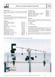
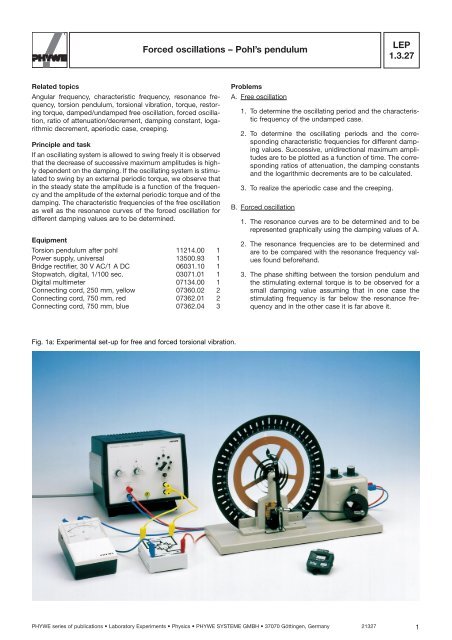
Fig. 1a: Experimental set-up for free and forced torsional vibration.<br />
Problems<br />
A. Free oscillation<br />
<strong>LEP</strong><br />
<strong>1.3.27</strong><br />
1. To determine the oscillating period and the characteristic<br />
frequency of the undamped case.<br />
2. To determine the oscillating periods and the corresponding<br />
characteristic frequencies for different damping<br />
values. Successive, unidirectional maximum amplitudes<br />
are to be plotted as a function of time. The corresponding<br />
ratios of attenuation, the damping constants<br />
and the logarithmic decrements are to be calculated.<br />
3. To realize the aperiodic case and the creeping.<br />
B. <strong>Forced</strong> oscillation<br />
1. The resonance curves are to be determined and to be<br />
represented graphically using the damping values of A.<br />
2. The resonance frequencies are to be determined and<br />
are to be compared with the resonance frequency values<br />
found beforehand.<br />
3. The phase shifting between the torsion <strong>pendulum</strong> and<br />
the stimulating external torque is to be observed for a<br />
small damping value assuming that in one case the<br />
stimulating frequency is far below the resonance frequency<br />
and in the other case it is far above it.<br />
PHYWE series of publications • Laboratory Experiments • Physics • PHYWE SYSTEME GMBH • 37070 Göttingen, Germany 21327 1
2<br />
<strong>LEP</strong><br />
<strong>1.3.27</strong><br />
Fig. 1b: Electrical connection of the experiment.<br />
Set-up and procedure<br />
The experiment is set up as shown in Fig. 1a und 1b. The DC<br />
output U_ of the power supply unit is connected to the two<br />
upper sockets of the DC motor. The eddy current brake also<br />
needs DC voltage. For this reason a rectifier is inserted<br />
between the AC output U_ of the power supply unit and the<br />
entrance to the eddy current brake. The DC current supplied<br />
to the eddy current brake, � B , is indicated by the ammeter.<br />
To determine the characteristic frequency w0 of the torsion<br />
<strong>pendulum</strong> without damping (�B = 0), the time for several <strong>oscillations</strong><br />
is measured repeatedly and the mean value of the peri-<br />
od —<br />
T 0 calculated. In the same way the characteristic frequen-<br />
cies for the damped <strong>oscillations</strong> are found using the following<br />
current intensities for the eddy current brake:<br />
� B � 0.25 A, (U � = 4 V)<br />
� B � 0.40 A, (U � = 6 V)<br />
� B � 0.55 A, (U � = 8 V)<br />
� B � 0.9 A, (U � = 12 V)<br />
To determine the damping values for the above mentioned<br />
cases the decrease in amplitude is measured by deflecting the<br />
<strong>pendulum</strong> completely to one side while observing the magnitude<br />
of successive amplitudes on the other side. Initially it has<br />
to be ensured that the <strong>pendulum</strong> pointer at rest coincides with<br />
the zero-position of the scale. This can be achieved by turning<br />
the eccentric disc of the motor.<br />
To realize the aperiodic case (� B � 1.5 A) and the creeping<br />
case (� B � 2.0 A) the eddy current brake is briefly connected<br />
directly to the DC output Uof the power supply unit.<br />
To stimulate the torsion <strong>pendulum</strong>, the connecting rod of the<br />
motor is fixed to the upper third of the stimulating source. The<br />
DC voltage U_ of the power supply unit must be set to maxi-<br />
<strong>Forced</strong> <strong>oscillations</strong> <strong>–</strong> Pohl’s <strong>pendulum</strong><br />
mum. The stimulating frequency � a of the motor can be found<br />
by using a stopwatch and counting the number of turns. The<br />
measurement begins with small frequencies. � a is increased<br />
by means of the motor-potentiometer setting “coarse”. In the<br />
vincinity of the maximum � a is changed in small steps using<br />
the potentiometer setting “fine”. In each case, readings should<br />
only be taken after a stable <strong>pendulum</strong> amplitude has been<br />
established. In the absence of damping or for only very small<br />
damping values, � a must be chosen in such a way that the<br />
<strong>pendulum</strong> does not exceed its scale range.<br />
Theory and evaluation<br />
A. Undamped and damped free oscillation In case of free and<br />
damped torsional vibration torques M1 (spiral spring) and M2 (eddy current brake) act on the <strong>pendulum</strong>. We have<br />
M 1 = <strong>–</strong> D 0 � and M 2 = <strong>–</strong> C�<br />
� = angle of rotation<br />
� · = angular velocity<br />
D 0 = torque per unit angle<br />
C = factor of proportionality depending on the current<br />
which supplies the eddy current brake<br />
The resultant torque<br />
M = <strong>–</strong> D 0 � <strong>–</strong> C�<br />
leads us to the following equation of motion:<br />
��¨ + C�� + D 0 � = 0 (1)<br />
� = <strong>pendulum</strong>’s moment of inertia<br />
�¨ = angular acceleration<br />
Dividing Eq. (1) by � and using the abbreviations<br />
� = and �2 0 =<br />
D0 C<br />
results in<br />
�¨ + 2�� + �2 0� = 0 (2)<br />
� is called the “damping constant” and<br />
21327 PHYWE series of publications • Laboratory Experiments • Physics • PHYWE SYSTEME GMBH • 37070 Göttingen, Germany<br />
� 0 =<br />
the characteristic frequency of the undamped system.<br />
The solution of the differential equation (2) is<br />
with<br />
2�<br />
�(t) = � 0 e -�t cos �t (3)<br />
� = (4)<br />
Eq. (3) shows that the amplitude �(t) of the damped oscillation<br />
has decreased to the e-th part of the initial amplitude � 0 after<br />
the time t = 1/6 has elapsed. Moreover, from Eq. (3) it follows<br />
that the ratio of two successive amplitudes is constant.<br />
� n<br />
� n�1<br />
� D0<br />
�<br />
�� 2 0 <strong>–</strong> � 2<br />
�<br />
= K = e �T (5)<br />
R
R<br />
K is called the “damping ratio” and the quantity<br />
� = ln K = �T = ln (6)<br />
is called the “logarithmic decrement”. Eq. (4) has a real solution<br />
only if<br />
� 2 0 ��2 .<br />
For � 2 0 = �2 , the <strong>pendulum</strong> returns in a minimum of time to its<br />
initial position without oscillating (aperiodic case). For � 2 0 < �2 ,<br />
the <strong>pendulum</strong> returns asymptotically to its initial position<br />
(creeping).<br />
B. <strong>Forced</strong> oscillation<br />
If the <strong>pendulum</strong> is acted on by a periodic torque M a = M 0 cos<br />
� a t Eq. (2) changes into<br />
�¨ + 2�� + �2 0� = F0 cos �at (7)<br />
M<br />
where F 0<br />
0 =<br />
In the steady state, the solution of this differential equation is<br />
where<br />
F<br />
and �0 = 0<br />
Furthermore:<br />
�(t) � � a cos (� a t <strong>–</strong> �) (8)<br />
�a = (9)<br />
��1 <strong>–</strong> � �a � 2 �<br />
� �2 � 2 0<br />
tan � =<br />
respectively<br />
� = arc tan<br />
2 ��a (10)<br />
An analysis of Eq. (9) gives evidence of the following:<br />
1. The greater F 0, the greater � a<br />
2. For a fixed value F0 we have:<br />
� � �max for �a � �0 3. The greater �, the smaller � a<br />
4. For � = 0 we find:<br />
�a � � if �a = �0 �<br />
2 �� a<br />
� 2 0 <strong>–</strong> � 2 a<br />
� 0 � 2<br />
� 2 0 <strong>–</strong> � 2 a<br />
�n �n�1 � 0<br />
� 0<br />
� a<br />
� 0 � 2<br />
Fig. 2 shows the phase difference of the forced oscillation as<br />
a function of the stimulating frequency according to Eq. (10).<br />
For very small frequencies � a the phase difference is approximately<br />
zero, i.e. the <strong>pendulum</strong> and the stimulating torque are<br />
“inphase”. If � a is much greater than � 0 ,<strong>pendulum</strong> and stimulating<br />
torque are nearly in opposite phase to each other.<br />
<strong>Forced</strong> <strong>oscillations</strong> <strong>–</strong> Pohl’s <strong>pendulum</strong><br />
<strong>LEP</strong><br />
<strong>1.3.27</strong><br />
Fig. 2: Phase shifting of forced oscillation for different dampings.<br />
The smaller the damping, the faster the transition from swinging<br />
“inphase” to the “in opposite phase” state can be achieved.<br />
The mean value of the period —<br />
T0 and the corresponding characteristic<br />
frequency <strong>–</strong> �0 of the free and undamped swinging<br />
torsional <strong>pendulum</strong> are found to be<br />
—<br />
T0 = (1.817 ± 0.017) sec; �—<br />
� —<br />
T0 and <strong>–</strong> � 0 = (3.46 ± 0.03) sec -1<br />
T 0 = ± 1%<br />
Fig. 3 illustrates the decrease in the unidirectional amplitude<br />
values as a function of time for free oscillation and different<br />
dampings.<br />
Fig. 4 shows the resonance curves for different dampings.<br />
Evaluating the curves leads to medium resonance frequency<br />
� = 3.41 s <strong>–</strong>1 .<br />
Table 1 indicates the characteristic damping values.<br />
�/A /s �/s -1 � = K = _��_<br />
�� 2 0 <strong>–</strong> � 2 /s<br />
0.25 16.7 0.06 3.46 1.1 0.12<br />
0.40 6.2 0.16 3.45 1.4 0.31<br />
0.55 3.2 0.31 3.44 1.9 0.64<br />
0.90 1.1 0.91 3.34 5.6 1.72<br />
PHYWE series of publications • Laboratory Experiments • Physics • PHYWE SYSTEME GMBH • 37070 Göttingen, Germany 21327 3<br />
�<br />
�<br />
�<br />
�<br />
n<br />
n�1
<strong>LEP</strong><br />
<strong>1.3.27</strong><br />
<strong>Forced</strong> <strong>oscillations</strong> <strong>–</strong> Pohl’s <strong>pendulum</strong><br />
Fig. 3: Maximum values of unidirectional amplitudes as a function of time for different dampings.<br />
Fig. 4: Resonance curves for different dampings.<br />
4<br />
21327 PHYWE series of publications • Laboratory Experiments • Physics • PHYWE SYSTEME GMBH • 37070 Göttingen, Germany<br />
R