SUNNY BACKUP 5000 - SMA Solar Technology AG
SUNNY BACKUP 5000 - SMA Solar Technology AG
SUNNY BACKUP 5000 - SMA Solar Technology AG

You also want an ePaper? Increase the reach of your titles
YUMPU automatically turns print PDFs into web optimized ePapers that Google loves.
Sunny Backup <strong>5000</strong><br />
Installation & Instruction Manual<br />
Technical Description Version 1.1 SBU<strong>5000</strong>-TEN081211<br />
IMEN-SBU<strong>5000</strong>
Home Screen<br />
100# METERS<br />
200# SETTINGS<br />
300# DI<strong>AG</strong>NOSIS<br />
400# HISTORY<br />
500# OPERATION<br />
600# DIRECT ACCESS<br />
110# Inverter Meters<br />
120# Battery Meters<br />
130# Backup Meters<br />
150# Compact Meters<br />
210# Inverter Settings<br />
220# Battery Settings<br />
230# Backup Settings<br />
240# Relay Settings<br />
250# System Settings<br />
260# Password Setting<br />
310# Inverter Diagnosis<br />
320# Battery Diagnosis<br />
330# Backup Diagnosis<br />
410# Failures Current<br />
420# Failure History<br />
430# Event History<br />
510# Operation Inverter<br />
520# Operation Battery<br />
530# Operation Backup<br />
540# Operation Generator<br />
550# Operation MMC<br />
Select Name:<br />
Select Number:<br />
111# Inverter Total Meters<br />
112# Inverter Device Meters<br />
131# Total Meters<br />
132# Grid State<br />
133# Generator State<br />
134# Device Meters<br />
221# Battery Property<br />
222# Battery Charge Mode<br />
223# Battery Protect Mode<br />
224# Battery Silent Mode<br />
231# General<br />
232# Grid Control<br />
233# Generator Control<br />
234# Generator Start<br />
235# Authentification<br />
241# Relay General<br />
242# Relay Load<br />
243# Relay Timer<br />
311# Total System Diag<br />
312# Inverter Device Diag<br />
331# Grid Diag<br />
332# Generator Diag
<strong>SMA</strong> Technologie <strong>AG</strong> Table of Contents<br />
Table of Contents<br />
1 Notes on this Manual. . . . . . . . . . . . . . . . . . . . . . 9<br />
1.1 Validity . . . . . . . . . . . . . . . . . . . . . . . . . . . . . . . . . 9<br />
1.2 Symbols Used . . . . . . . . . . . . . . . . . . . . . . . . . . . . 9<br />
1.3 Syntax. . . . . . . . . . . . . . . . . . . . . . . . . . . . . . . . . 10<br />
2 The Sunny Backup <strong>5000</strong> . . . . . . . . . . . . . . . . . . 11<br />
2.1 Properties . . . . . . . . . . . . . . . . . . . . . . . . . . . . . . 11<br />
2.2 At a Glance. . . . . . . . . . . . . . . . . . . . . . . . . . . . . 18<br />
2.3 Dimensions . . . . . . . . . . . . . . . . . . . . . . . . . . . . . 19<br />
2.4 Scope of Delivery Sunny Backup <strong>5000</strong> . . . . . . . . . 20<br />
2.5 Required Tools and Resources . . . . . . . . . . . . . . . . 21<br />
2.6 Accessories (Optional) . . . . . . . . . . . . . . . . . . . . . 22<br />
2.7 <strong>SMA</strong> Products (Optional) . . . . . . . . . . . . . . . . . . . 22<br />
2.8 Name Plate/Firmware Version . . . . . . . . . . . . . . . . 23<br />
3 Safety Instructions . . . . . . . . . . . . . . . . . . . . . . . 25<br />
3.1 Important Notes Regarding Operation . . . . . . . . . . 25<br />
3.2 Potential Hazards . . . . . . . . . . . . . . . . . . . . . . . . . 26<br />
4 Installation . . . . . . . . . . . . . . . . . . . . . . . . . . . . . 29<br />
4.1 Lifting/Moving . . . . . . . . . . . . . . . . . . . . . . . . . . . 29<br />
4.2 Unpacking. . . . . . . . . . . . . . . . . . . . . . . . . . . . . . 29<br />
4.3 Minimum Clearance . . . . . . . . . . . . . . . . . . . . . . . 30<br />
4.4 Wall Mounting. . . . . . . . . . . . . . . . . . . . . . . . . . . 31<br />
4.5 Installing Batteries. . . . . . . . . . . . . . . . . . . . . . . . . 35<br />
5 Opening and Closing . . . . . . . . . . . . . . . . . . . . . 37<br />
5.1 Opening and Closing of the Sunny Backup <strong>5000</strong> . . 37<br />
5.2 Opening and Closing of the Automatic Switch Box . 38<br />
Technical Description SBU<strong>5000</strong>-TEN081211 Page 3
Table of Contents <strong>SMA</strong> Technologie <strong>AG</strong><br />
6 Electrical Connection . . . . . . . . . . . . . . . . . . . . . 39<br />
6.1 Grounding. . . . . . . . . . . . . . . . . . . . . . . . . . . . . . 40<br />
6.2 DC Connection . . . . . . . . . . . . . . . . . . . . . . . . . . 42<br />
6.2.1 Safety Precautions/Conditions . . . . . . . . . . . . . . . . . . . . . . . . .42<br />
6.2.2 Cable Protection . . . . . . . . . . . . . . . . . . . . . . . . . . . . . . . . . .43<br />
6.2.3 Connection . . . . . . . . . . . . . . . . . . . . . . . . . . . . . . . . . . . . . .43<br />
6.2.4 Battery Connection Box (SBU-CON.33) . . . . . . . . . . . . . . . . . .44<br />
6.3 AC Connection . . . . . . . . . . . . . . . . . . . . . . . . . . 46<br />
6.4 Additional Connections . . . . . . . . . . . . . . . . . . . . . 47<br />
6.4.1 Battery Temperature Sensor . . . . . . . . . . . . . . . . . . . . . . . . . .47<br />
6.4.2 Battery Current Sensor . . . . . . . . . . . . . . . . . . . . . . . . . . . . . .49<br />
6.4.3 Communication for Multi-device Connection . . . . . . . . . . . . . . .51<br />
6.4.4 Multi-function Relay 1 and 2 . . . . . . . . . . . . . . . . . . . . . . . . . .53<br />
6.4.5 BatVtgOut Power Supply . . . . . . . . . . . . . . . . . . . . . . . . . . . .56<br />
6.4.6 Digital Input, DigIn . . . . . . . . . . . . . . . . . . . . . . . . . . . . . . . . .57<br />
6.5 Interface for External Communication . . . . . . . . . . . 58<br />
6.5.1 Connection of the Interface . . . . . . . . . . . . . . . . . . . . . . . . . . .59<br />
6.5.2 Data Transmission Speed . . . . . . . . . . . . . . . . . . . . . . . . . . . .61<br />
6.6 GenMan Connection . . . . . . . . . . . . . . . . . . . . . . 62<br />
6.7 Automatic Switch Box Connection . . . . . . . . . . . . . 63<br />
6.7.1 Feeding in the Energy Cables . . . . . . . . . . . . . . . . . . . . . . . . .63<br />
6.7.2 Feeding in the Control and Measurement Cables . . . . . . . . . . .64<br />
6.7.3 Supply Line (X1/Load Meter) . . . . . . . . . . . . . . . . . . . . . . . . .67<br />
6.7.4 Sunny Backup <strong>5000</strong> (X2/Sunny Backup) . . . . . . . . . . . . . . . . .68<br />
6.7.5 Consumer System (X3/Backup Loads) . . . . . . . . . . . . . . . . . . .68<br />
6.7.6 PV System (X4/PV System) . . . . . . . . . . . . . . . . . . . . . . . . . . .69<br />
6.7.7 PV Feed-in Counter (X5/PV Meter). . . . . . . . . . . . . . . . . . . . . .71<br />
6.7.8 Generator (X6/Generator) . . . . . . . . . . . . . . . . . . . . . . . . . . .71<br />
6.7.9 Signal-controlled feeding (X7/Feed In Signal) . . . . . . . . . . . . . .72<br />
6.7.10 ComSync Communication Cable . . . . . . . . . . . . . . . . . . . . . . .72<br />
6.7.11 BackupVtgCur External Control Lines and Measurement<br />
Cables . . . . . . . . . . . . . . . . . . . . . . . . . . . . . . . . . . . . . . . . .72<br />
6.7.12 Concluding Tasks . . . . . . . . . . . . . . . . . . . . . . . . . . . . . . . . . .73<br />
Page 4 SBU<strong>5000</strong>-TEN081211 Technical Description
<strong>SMA</strong> Technologie <strong>AG</strong> Table of Contents<br />
7 Control Elements . . . . . . . . . . . . . . . . . . . . . . . . 74<br />
7.1 Display Messages . . . . . . . . . . . . . . . . . . . . . . . . 74<br />
7.2 DC Circuit Breaker . . . . . . . . . . . . . . . . . . . . . . . . 74<br />
7.3 Buttons . . . . . . . . . . . . . . . . . . . . . . . . . . . . . . . . 75<br />
7.4 Meaning of the Light-emitting Diodes (LEDs) . . . . . . 75<br />
7.5 MMC/SD Card . . . . . . . . . . . . . . . . . . . . . . . . . . 75<br />
8 (First) Commissioning . . . . . . . . . . . . . . . . . . . . . 77<br />
8.1 Requirements . . . . . . . . . . . . . . . . . . . . . . . . . . . . 77<br />
8.2 Starting the Quick Configuration Guide (QCG) . . . . 77<br />
9 Activation and Deactivation . . . . . . . . . . . . . . . . 81<br />
9.1 Activation / Startup . . . . . . . . . . . . . . . . . . . . . . . 81<br />
9.2 Stopping . . . . . . . . . . . . . . . . . . . . . . . . . . . . . . . 82<br />
9.3 Deactivation. . . . . . . . . . . . . . . . . . . . . . . . . . . . . 83<br />
9.4 Disconnecting the Device from Voltage Sources. . . . 83<br />
9.5 Reactivating the Device Following Automatic<br />
Shutdown . . . . . . . . . . . . . . . . . . . . . . . . . . . . . . 84<br />
10 Operation . . . . . . . . . . . . . . . . . . . . . . . . . . . . . 85<br />
10.1 Menu Structure. . . . . . . . . . . . . . . . . . . . . . . . . . . 87<br />
10.2 Changing Parameters . . . . . . . . . . . . . . . . . . . . . . 90<br />
10.3 Direct Access . . . . . . . . . . . . . . . . . . . . . . . . . . . . 91<br />
10.4 Compact Meters. . . . . . . . . . . . . . . . . . . . . . . . . . 91<br />
10.5 Entering the Installer Password . . . . . . . . . . . . . . . . 94<br />
10.6 Display Messages (Overview) . . . . . . . . . . . . . . . . 96<br />
10.7 Entering the Installer Identification . . . . . . . . . . . . . 98<br />
10.8 Parameter Display . . . . . . . . . . . . . . . . . . . . . . . . 99<br />
10.9 Display of Events . . . . . . . . . . . . . . . . . . . . . . . . . 99<br />
10.10 Display of Warnings and Errors . . . . . . . . . . . . . . 100<br />
Technical Description SBU<strong>5000</strong>-TEN081211 Page 5
Table of Contents <strong>SMA</strong> Technologie <strong>AG</strong><br />
11 Archiving Data on an MMC/SD Card. . . . . . . . 101<br />
11.1 Inserting the Card. . . . . . . . . . . . . . . . . . . . . . . . 103<br />
11.2 Removing the Card. . . . . . . . . . . . . . . . . . . . . . . 104<br />
11.3 Saving and Loading Parameters. . . . . . . . . . . . . . 104<br />
11.4 Writing Log Data . . . . . . . . . . . . . . . . . . . . . . . . 105<br />
11.5 Status Messages. . . . . . . . . . . . . . . . . . . . . . . . . 105<br />
11.6 Firmware Update . . . . . . . . . . . . . . . . . . . . . . . . 106<br />
12 Inverter Operation . . . . . . . . . . . . . . . . . . . . . . 108<br />
12.1 Overload and Short-circuit Behavior . . . . . . . . . . . 108<br />
12.2 Device Faults and Autostart . . . . . . . . . . . . . . . . . 108<br />
13 Grid . . . . . . . . . . . . . . . . . . . . . . . . . . . . . . . . . 109<br />
13.1 Conditions . . . . . . . . . . . . . . . . . . . . . . . . . . . . . 109<br />
13.2 Operating on the Public Grid. . . . . . . . . . . . . . . . 110<br />
13.3 Grid Failure . . . . . . . . . . . . . . . . . . . . . . . . . . . . 110<br />
13.4 Stand-Alone Grid Operation . . . . . . . . . . . . . . . . 110<br />
13.5 Grid Reconnection . . . . . . . . . . . . . . . . . . . . . . . 110<br />
13.6 Limits and Power Adjustment . . . . . . . . . . . . . . . . 111<br />
13.7 Grid feeding from the battery. . . . . . . . . . . . . . . . 112<br />
13.7.1 Time-dependent grid feeding . . . . . . . . . . . . . . . . . . . . . . . . .113<br />
13.7.2 Signal-controlled grid feeding . . . . . . . . . . . . . . . . . . . . . . . .113<br />
14 Battery Management . . . . . . . . . . . . . . . . . . . . 115<br />
14.1 Battery Temperature . . . . . . . . . . . . . . . . . . . . . . 115<br />
14.2 Start Options . . . . . . . . . . . . . . . . . . . . . . . . . . . 116<br />
14.3 State of Charge/SOC and SOH . . . . . . . . . . . . . 116<br />
14.4 Charge Control . . . . . . . . . . . . . . . . . . . . . . . . . 117<br />
14.4.1 Boost Charge . . . . . . . . . . . . . . . . . . . . . . . . . . . . . . . . . . .119<br />
14.4.2 Full Charge . . . . . . . . . . . . . . . . . . . . . . . . . . . . . . . . . . . . .119<br />
14.4.3 Equalization Charge. . . . . . . . . . . . . . . . . . . . . . . . . . . . . . .120<br />
Page 6 SBU<strong>5000</strong>-TEN081211 Technical Description
<strong>SMA</strong> Technologie <strong>AG</strong> Table of Contents<br />
14.4.4 Silent Mode . . . . . . . . . . . . . . . . . . . . . . . . . . . . . . . . . . . .120<br />
14.4.5 Manual Equalization Charge . . . . . . . . . . . . . . . . . . . . . . . .120<br />
14.5 Battery Preservation Mode . . . . . . . . . . . . . . . . . 121<br />
14.6 Battery Diagnostics . . . . . . . . . . . . . . . . . . . . . . . 122<br />
15 Connecting a Generator . . . . . . . . . . . . . . . . . 123<br />
15.1 Generator Start . . . . . . . . . . . . . . . . . . . . . . . . . 123<br />
15.2 Generator Operation . . . . . . . . . . . . . . . . . . . . . 125<br />
15.2.1 Manual Generator Operation . . . . . . . . . . . . . . . . . . . . . . . .125<br />
15.2.2 Automatic Generator Operation . . . . . . . . . . . . . . . . . . . . . .126<br />
15.3 Limits and Power Adjustment . . . . . . . . . . . . . . . . 128<br />
15.4 Run Times . . . . . . . . . . . . . . . . . . . . . . . . . . . . . 129<br />
15.5 Operation Together With Sunny Boys. . . . . . . . . . 130<br />
15.6 Stopping the Generator . . . . . . . . . . . . . . . . . . . 130<br />
15.7 Stopping the Sunny Backup <strong>5000</strong> . . . . . . . . . . . . 131<br />
15.8 Failures . . . . . . . . . . . . . . . . . . . . . . . . . . . . . . . 131<br />
16 Relay . . . . . . . . . . . . . . . . . . . . . . . . . . . . . . . . 133<br />
17 Sunny Boy . . . . . . . . . . . . . . . . . . . . . . . . . . . . 135<br />
17.1 Setting the Stand-alone Grid Parameters . . . . . . . . 135<br />
17.2 Frequency Shift Power Control (FSPC) . . . . . . . . . 137<br />
18 Maintenance and Care . . . . . . . . . . . . . . . . . . 139<br />
18.1 Housing. . . . . . . . . . . . . . . . . . . . . . . . . . . . . . . 139<br />
18.2 Cleaning the Fans. . . . . . . . . . . . . . . . . . . . . . . . 139<br />
18.3 Display . . . . . . . . . . . . . . . . . . . . . . . . . . . . . . . 139<br />
18.4 Functioning . . . . . . . . . . . . . . . . . . . . . . . . . . . . 139<br />
18.5 Battery . . . . . . . . . . . . . . . . . . . . . . . . . . . . . . . 140<br />
18.6 Disposal . . . . . . . . . . . . . . . . . . . . . . . . . . . . . . 140<br />
18.7 Sunny Backup System Test. . . . . . . . . . . . . . . . . . 140<br />
Technical Description SBU<strong>5000</strong>-TEN081211 Page 7
Table of Contents <strong>SMA</strong> Technologie <strong>AG</strong><br />
19 Parameter Lists. . . . . . . . . . . . . . . . . . . . . . . . . 141<br />
19.1 Display Values . . . . . . . . . . . . . . . . . . . . . . . . . . 142<br />
19.2 Adjustable System Parameters . . . . . . . . . . . . . . . 145<br />
19.3 Diagnostics . . . . . . . . . . . . . . . . . . . . . . . . . . . . 154<br />
19.4 Events, Warnings and Errors (History). . . . . . . . . . 156<br />
19.5 Functions in Operation . . . . . . . . . . . . . . . . . . . . 156<br />
20 Troubleshooting/Problem Solving . . . . . . . . . . 159<br />
20.1 Error Confirmation . . . . . . . . . . . . . . . . . . . . . . . 159<br />
20.2 Autostart Handling . . . . . . . . . . . . . . . . . . . . . . . 159<br />
20.3 Master Slave Handling . . . . . . . . . . . . . . . . . . . . 159<br />
20.4 Handling Pending Errors During the Booting<br />
Procedure . . . . . . . . . . . . . . . . . . . . . . . . . . . . . 160<br />
20.5 Display of Errors and Events . . . . . . . . . . . . . . . . 160<br />
20.6 Events . . . . . . . . . . . . . . . . . . . . . . . . . . . . . . . . 161<br />
20.7 Error Categories. . . . . . . . . . . . . . . . . . . . . . . . . 163<br />
20.8 Warnings and Error Messages. . . . . . . . . . . . . . . 163<br />
20.9 Troubleshooting . . . . . . . . . . . . . . . . . . . . . . . . . 168<br />
21 Technical Data . . . . . . . . . . . . . . . . . . . . . . . . . 175<br />
21.1 Sunny Backup <strong>5000</strong> . . . . . . . . . . . . . . . . . . . . . . 175<br />
21.2 Automatic Switch Box . . . . . . . . . . . . . . . . . . . . . 178<br />
21.3 Battery Connection Box (SBU-CON.33) . . . . . . . . 180<br />
22 Certificates . . . . . . . . . . . . . . . . . . . . . . . . . . . . 181<br />
23 Contact. . . . . . . . . . . . . . . . . . . . . . . . . . . . . . . 183<br />
24 Glossary . . . . . . . . . . . . . . . . . . . . . . . . . . . . . 184<br />
Page 8 SBU<strong>5000</strong>-TEN081211 Technical Description
<strong>SMA</strong> Technologie <strong>AG</strong> Notes on this Manual<br />
1 Notes on this Manual<br />
This technical description is intended for both the installer as well as the end customer.<br />
It is intended to assist in correctly mounting, installing and operating as well as<br />
understanding the operating principles of a Sunny Backup system.<br />
Information regarding the following subjects can be found in the specified sections:<br />
• Installation starting in section 2 "The Sunny Backup <strong>5000</strong>" (Page 11)<br />
• Commissioning starting in section 7 "Control Elements" (Page 74)<br />
• Functionality starting in section 12 "Inverter Operation" (Page 108)<br />
• Appendix starting in section 18 "Maintenance and Care" (Page 139)<br />
1.1 Validity<br />
This technical description applies to firmware version 3.004 and above, and to<br />
hardware version T and above (2.8 "Name Plate/Firmware Version" (Page 23)).<br />
You can read the firmware version of your device on the display using the "312.02<br />
FwVer" parameter (see section 19.3 "Diagnostics" (Page 154)).<br />
This product may only be operated within the intended area of application described<br />
in this documentation.<br />
Do not use the Sunny Backup <strong>5000</strong> for purposes other than those indicated in this<br />
technical description. Use of the device for other purposes can void the warranty as<br />
well as damage both the device and the system.<br />
If you require further information, please contact the Sunny Island Hotline at<br />
+49 561 95 22 399 or by e-mail: SunnyIsland.Service@<strong>SMA</strong>.de.<br />
1.2 Symbols Used<br />
To ensure optimum use of this manual, note the following explanations of symbols used.<br />
This symbol indicates a danger.<br />
If these instructions are ignored, a significant danger of injury or death<br />
arises and damage to the device, system or plant may also result.<br />
This symbol indicates a notice.<br />
Failure to observe this notice can make a working step more difficult, and may<br />
hinder optimum operation of the device.<br />
This symbol indicates an example.<br />
Here you will find supplementary examples on concrete topics.<br />
Technical Description SBU<strong>5000</strong>-TEN081211 Page 9
Notes on this Manual <strong>SMA</strong> Technologie <strong>AG</strong><br />
1.3 Syntax<br />
The syntax specified here for menus and parameters apply to the entire document:<br />
Menu: menu number, hash and menu name (150# Grid Meters)<br />
Parameter: menu number, dot, parameter number and parameter name<br />
(150.01 GdRmgTm)<br />
Page 10 SBU<strong>5000</strong>-TEN081211 Technical Description
<strong>SMA</strong> Technologie <strong>AG</strong> The Sunny Backup <strong>5000</strong><br />
2 The Sunny Backup <strong>5000</strong><br />
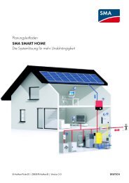
2.1 Properties<br />
The Sunny Backup system comprises one or more Sunny Backup <strong>5000</strong>s in combination<br />
with an Automatic Switch Box (AS-Box-M, AS-Box-L or AS-Box-XL). This system is<br />
specially designed for backup applications and enables, in compliance with all<br />
standard requirements, continued operation of a grid-connected PV system in the event<br />
of grid failure. Thus, this system does not replace the conventional PV inverter (Sunny<br />
Boy), but is installed additionally. In the event of grid failure, the Sunny Backup system<br />
first ensures safe disconnection of the loads and the PV system from the public grid, and<br />
subsequently forms a stable stand-alone grid, into which the Sunny Boy can then feed<br />
solar energy. The maximum period of interruption for the loads is approximately 20 ms,<br />
which for most loads is equivalent to uninterrupted operation.<br />
Public grid<br />
PV feed-in counter<br />
Generator<br />
0 0 7 8 5 5 6 kWh<br />
Reference<br />
counter<br />
0 0 7 8 5 5 6 kWh<br />
Sunny Backup system<br />
Switching device<br />
Automatic disconnection<br />
device for PV systems<br />
Grid/Stand-alone grid<br />
contactor<br />
Generator<br />
contactor<br />
Sunny<br />
Backup<br />
<strong>5000</strong><br />
Battery<br />
The Sunny Backup system is suitable for use in conjunction with all Sunny Boys and<br />
Sunny Mini Centrals from <strong>SMA</strong> Technologie <strong>AG</strong>. The modular structure allows the<br />
suitable construction of systems with a maximum consumer power of approximately 5<br />
kW to 100 kW. The Sunny Backup system can be integrated into new PV system<br />
installations, and can also be retrofitted onto existing PV systems.<br />
Along with the Sunny Backup <strong>5000</strong> inverter and the automatic switching device, a<br />
battery is necessary as a short-term storage device, for reliable operation. During grid<br />
failure, the battery has the task of correcting the imbalance between generation and<br />
consumption. Whenever less energy is being generated than consumed (e.g. at night),<br />
Technical Description SBU<strong>5000</strong>-TEN081211 Page 11<br />
Sunny Sunny Backup Backup <strong>5000</strong> <strong>5000</strong><br />
ESC ESC<br />
ENTER ENTER<br />
PV coupling<br />
contactor<br />
Betrieb<br />
Operation<br />
Erdschluss<br />
Earth Fault<br />
Störung<br />
Failure<br />
PV system<br />
Loads
The Sunny Backup <strong>5000</strong> <strong>SMA</strong> Technologie <strong>AG</strong><br />
the battery is discharged. Whenever more energy is being generated than consumed<br />
(e.g. during the day), the battery is charged. The intelligent battery management built<br />
into the Sunny Backup <strong>5000</strong> protects the battery from overcharging and deep<br />
discharge. This ensures that the battery service life stipulated by the battery<br />
manufacturer can be achieved.<br />
All regulation and control is performed by the Sunny Backup <strong>5000</strong>. If the system is in<br />
grid-parallel operation, the Sunny Backup <strong>5000</strong> ensures standard-compliant grid<br />
monitoring and battery-preserving charging. The Sunny Backup <strong>5000</strong> is extremely<br />
quick to detect any failure of the public grid, and sends the command to the switching<br />
device to disconnect the system from the grid. After a maximum of 20 ms, the loads will<br />
be already supplied with electricity again, from the battery. After a matter of seconds,<br />
the PV system switches to this stand-alone grid, and either powers the loads, or is used<br />
for recharging the batteries. The efficiency during charging, regardless of whether from<br />
the grid, or from the PV system, and during discharging, is up to 95 %. Due to the Sunny<br />
Backup <strong>5000</strong>'s very high overload capability of up to 8.4 kW for 60 seconds, and its<br />
integrated smooth startup, critical loads with very high start currents can also be started<br />
safely. Thus, over-dimensioning of the inverter is not necessary.<br />
The Sunny Backup system meets all requirements of the VDE 0126-1-1 directive,<br />
which is necessary in Germany. The switching devices for PV feeding are<br />
implemented redundantly, and are monitored. The safety of this system has been<br />
inspected and certified by the German Professional Association for Precision<br />
Engineering and Electrotechnology.<br />
The Sunny Backup system is only intended for use in TN grids!<br />
The automatic switching device is also available with an optional additional connection<br />
for an emergency power generator. Thus, the system's reliability of supply can be<br />
increased further, and a smaller battery can be used. In this case, the Sunny Backup<br />
<strong>5000</strong> also conducts the startup and synchronization of the emergency power<br />
generator, and connects it to the consumer grid with the switching device. The<br />
generator now powers the loads, and charges the batteries. Once the batteries are<br />
charged sufficiently, the Sunny Backup <strong>5000</strong> automatically stops the generator.<br />
Despite the complex functions of the Sunny Backup system, it can be installed and<br />
configured with ease. All special material required for installation is included in the<br />
delivery. Additional sub-distribution units are generally not necessary. The safety and<br />
fuse protection concept on the consumer side, and that of the PV system, are generally<br />
not impaired by the Sunny Backup <strong>5000</strong>, and do not need to be adapted.<br />
All the settings required for operation can be quickly and easily programmed in six<br />
steps using the "Quick Configuration Guide". By employing the concept of central<br />
operation referred to as "Single Point of Operation", the parameters of a multi-phase<br />
Page 12 SBU<strong>5000</strong>-TEN081211 Technical Description
<strong>SMA</strong> Technologie <strong>AG</strong> The Sunny Backup <strong>5000</strong><br />
system are only set on the master device, and all other devices automatically adopt the<br />
configuration. The easy-to-understand menu navigation allows quick access to all<br />
important data, even while the system is running. An MMC/SD card provides<br />
uncomplicated system control, and thus makes any service work easier.<br />
Always use the MMC/SD card to save data and events. This is necessary in order<br />
for <strong>SMA</strong> Technologie <strong>AG</strong> to be able to help you in the event of a fault.<br />
The Sunny Backup System can also be used to realise a decentralised grid stabilisation.<br />
This battery grid feed feature enables the user to feed power from the batteries into the<br />
electrical grid when required. The feeding from the battery can be time-depedent or<br />
initiated via a external dry contact, for example ripple control signal which is sent from<br />
the energy supplier.<br />
Before using the battery grid feed feature, please contact your energy supplier in<br />
order to verify the local standards.<br />
The graphics on the next pages show the different wiring options (1-phase and 3phase).<br />
Technical Description SBU<strong>5000</strong>-TEN081211 Page 13
The Sunny Backup <strong>5000</strong> <strong>SMA</strong> Technologie <strong>AG</strong><br />
Single-phase Sunny Backup system<br />
Legend<br />
Phase<br />
Neutral conductor<br />
Protective earth<br />
Battery<br />
Battery temperature<br />
Synchronization bus<br />
Backup measurement<br />
cable<br />
Public Grid<br />
Equipotential<br />
bonding<br />
bar<br />
Foundation<br />
grounding<br />
electrode<br />
Generator<br />
PV<br />
feed-in<br />
counter<br />
0 2 5 3<br />
Reference<br />
counter<br />
0 2 5 3<br />
L<br />
N<br />
PE<br />
X5<br />
L<br />
N<br />
PE<br />
X1<br />
L1<br />
L2<br />
L3<br />
N<br />
PE<br />
X6<br />
L<br />
N<br />
PE<br />
Load meter PV meter<br />
Generator<br />
Automatic<br />
SwitchBox<br />
SBU<strong>5000</strong><br />
L N PE<br />
Page 14 SBU<strong>5000</strong>-TEN081211 Technical Description<br />
Betrieb<br />
Operation<br />
Erdschluss<br />
Earth Fault<br />
Störung<br />
Failure<br />
X2<br />
<strong>SUNNY</strong> <strong>BACKUP</strong><br />
AUTOMATIC SWITCHBOX<br />
Master<br />
AC1 L<br />
BackupVtg<br />
Cur<br />
Com<br />
Sync<br />
Out<br />
DC<br />
+ -<br />
Sunny Boy<br />
PV system<br />
X4<br />
L<br />
N<br />
PE<br />
ComSyncIn<br />
ComSyncOut<br />
MStr/L<br />
Sunny<br />
Island<br />
Betrieb<br />
Operation<br />
Erdschluss<br />
Earth Fault<br />
Störung<br />
Failure<br />
ESC ESC<br />
ENTER ENTER<br />
Backup loads<br />
N PE<br />
Battery<br />
X3<br />
L1<br />
L2<br />
L3<br />
N<br />
PE<br />
Betrieb<br />
Operation<br />
Erdschluss<br />
Earth Fault<br />
Störung<br />
Failure<br />
Com<strong>SMA</strong><br />
Out<br />
Com<br />
Sync<br />
In<br />
BatTmp<br />
Loads
<strong>SMA</strong> Technologie <strong>AG</strong> The Sunny Backup <strong>5000</strong><br />
Single-phase Sunny Backup system<br />
PV feed-in<br />
counter<br />
0 2 5 3<br />
Reference<br />
counter<br />
0 2 5 3<br />
Generator<br />
PV meter<br />
Load meter<br />
Generator<br />
X5<br />
L<br />
N<br />
PE<br />
X1<br />
L1<br />
L2<br />
L3<br />
N<br />
PE<br />
X6<br />
L<br />
N<br />
PE<br />
Legend<br />
Automatic disconnection<br />
device<br />
PV coupling contactor<br />
Grid isolation contactor<br />
I/O<br />
Isolation contactor<br />
Phase<br />
Neutral conductor<br />
Protective earth<br />
Power and<br />
measurement<br />
cables<br />
ComSyncIn<br />
ComSyncOut<br />
MStr/L1<br />
SLV1/L2<br />
SLV2/L3<br />
L N PE<br />
Sunny Backup<br />
Technical Description SBU<strong>5000</strong>-TEN081211 Page 15<br />
X2<br />
Sunny<br />
Island<br />
ESC ESC<br />
ENTER ENTER<br />
X4 Sunny Boy<br />
L<br />
N<br />
PE<br />
X3<br />
L1<br />
L2<br />
L3<br />
N<br />
PE<br />
PV system<br />
Backup loads<br />
Betrieb<br />
Operation<br />
Erdschluss<br />
Earth Fault<br />
Störung<br />
Failure<br />
Loads
The Sunny Backup <strong>5000</strong> <strong>SMA</strong> Technologie <strong>AG</strong><br />
Three-phase Sunny Backup system<br />
Legend<br />
Phase<br />
Neutral conductor<br />
Protective earth<br />
Battery<br />
Battery temperature<br />
Synchronization bus<br />
Backup measurement<br />
cable<br />
Public Grid<br />
Equipotential<br />
bonding<br />
bar<br />
Foundation<br />
grounding<br />
electrode<br />
Generator<br />
AC1 L N PE<br />
Com<br />
Sync<br />
Out<br />
ComSma<br />
Out<br />
Com<br />
Sync<br />
In<br />
X5<br />
L1<br />
L2<br />
L3<br />
N<br />
PE<br />
X1<br />
L1<br />
L2<br />
L3<br />
N<br />
PE<br />
AC1 L N PE<br />
Com<br />
Sync<br />
Out<br />
Automatic<br />
SwitchBox<br />
SBU<strong>5000</strong><br />
X2<br />
L3 L2 L1 N PE<br />
Slave 2 Slave 1 Master<br />
BackupVtg<br />
Cur<br />
DC<br />
+ -<br />
Sunny<br />
Island<br />
ESC ESC<br />
ENTER ENTER<br />
BatTmp<br />
PV<br />
feed-in<br />
counter<br />
0 2 5 3<br />
Reference<br />
counter<br />
0 2 5 3<br />
L1<br />
L2<br />
L3<br />
N<br />
PE<br />
X6<br />
L1<br />
L2<br />
L3<br />
N<br />
PE<br />
Load meter PV meter<br />
BackupVtg<br />
Cur<br />
DC<br />
+ -<br />
Generator<br />
Sunny<br />
Island<br />
ESC ESC<br />
ENTER ENTER<br />
ComSma<br />
Out<br />
Com<br />
Sync<br />
In<br />
BatTmp<br />
Page 16 SBU<strong>5000</strong>-TEN081211 Technical Description<br />
Betrieb<br />
Operation<br />
Erdschluss<br />
Earth Fault<br />
Störung<br />
Failure<br />
<strong>SUNNY</strong> <strong>BACKUP</strong><br />
AUTOMATIC SWITCHBOX<br />
Sunny Boy<br />
Betrieb<br />
Operation<br />
Erdschluss<br />
Earth Fault<br />
Störung<br />
Failure<br />
PV system<br />
Backup loads<br />
X4<br />
L1<br />
L2<br />
L3<br />
N<br />
PE<br />
X3<br />
L1<br />
L2<br />
L3<br />
N<br />
PE<br />
ComSyncIn<br />
ComSyncOut<br />
MStr/L1<br />
SLV1/L2<br />
SLV2/L3<br />
AC1 L N PE<br />
BackupVtg<br />
Cur<br />
Com<br />
Sync<br />
Out<br />
DC<br />
+ -<br />
Betrieb<br />
Operation<br />
Erdschluss<br />
Earth Fault<br />
Störung<br />
Failure<br />
Sunny<br />
Island<br />
ESC ESC<br />
ENTER ENTER<br />
Battery<br />
Loads<br />
ComSma<br />
Out<br />
Com<br />
Sync<br />
In<br />
BatTmp
<strong>SMA</strong> Technologie <strong>AG</strong> The Sunny Backup <strong>5000</strong><br />
Three-phase Sunny Backup system<br />
PV feed-in<br />
counter<br />
0 2 5 3<br />
Reference<br />
counter<br />
0 2 5 3<br />
Generator<br />
PV meter<br />
Load meter<br />
Generator<br />
X5<br />
L1<br />
L2<br />
L3<br />
N<br />
PE<br />
X1<br />
L1<br />
L2<br />
L3<br />
N<br />
PE<br />
X6<br />
L1<br />
L2<br />
L3<br />
N<br />
PE<br />
Legend<br />
Automatic disconnection<br />
device<br />
PV coupling contactor<br />
Grid isolation contactor<br />
I/O<br />
Isolation contactor<br />
Phase<br />
Neutral conductor<br />
Protective earth<br />
Power and<br />
measurement<br />
cables<br />
ComSyncIn<br />
ComSyncOut<br />
MStr/L1<br />
SLV1/L2<br />
SLV2/L3<br />
X2 L1 L2 L3 N PE<br />
Sunny Backup<br />
Technical Description SBU<strong>5000</strong>-TEN081211 Page 17<br />
Sunny<br />
Island<br />
ESC<br />
ENTER ENTER<br />
Sunny<br />
Island<br />
ESC<br />
ENTER ENTER<br />
Sunny<br />
Island<br />
ESC ESC<br />
ENTER ENTER<br />
X4 Sunny Boy<br />
L1<br />
L2<br />
L3<br />
N<br />
PE<br />
X3<br />
L1<br />
L2<br />
L3<br />
N<br />
PE<br />
PV system<br />
Backup loads<br />
Betrieb<br />
Operation<br />
Erdschluss<br />
Earth Fault<br />
Störung<br />
Failure<br />
Loads
The Sunny Backup <strong>5000</strong> <strong>SMA</strong> Technologie <strong>AG</strong><br />
2.2 At a Glance<br />
The following figure provides an overview of all control elements and connections of<br />
the Sunny Backup <strong>5000</strong>:<br />
Display<br />
DC circuit<br />
breaker<br />
LEDs showing device<br />
operation (green above,<br />
red below)<br />
AC connections DC connections<br />
Control buttons<br />
MMC/SD<br />
card<br />
Additional<br />
connections<br />
Page 18 SBU<strong>5000</strong>-TEN081211 Technical Description
<strong>SMA</strong> Technologie <strong>AG</strong> The Sunny Backup <strong>5000</strong><br />
2.3 Dimensions<br />
Sunny<br />
Island<br />
Operation<br />
Failure<br />
Utility interactive battery inverter<br />
ESC<br />
DC-Disconnect MMC/SD Card<br />
ENTER<br />
467 mm<br />
235 mm<br />
235 mm<br />
215 mm<br />
105 mm<br />
700 mm<br />
62 mm<br />
230 mm<br />
612 mm<br />
Upper edge of the<br />
device<br />
Upper edge<br />
wall bracket<br />
Display height<br />
Technical Description SBU<strong>5000</strong>-TEN081211 Page 19
The Sunny Backup <strong>5000</strong> <strong>SMA</strong> Technologie <strong>AG</strong><br />
2.4 Scope of Delivery Sunny Backup <strong>5000</strong><br />
The following elements are included:<br />
A<br />
Sunny<br />
Island<br />
ESC ESC<br />
ENTER ENTER<br />
C<br />
K<br />
Typ:<br />
Seriennummer:<br />
Datum der Inbetriebnahme:<br />
Anschrift:<br />
Installationsbetrieb<br />
Typ:<br />
Seriennummer:<br />
Datum der Inbetriebnahme:<br />
Anschrift:<br />
Installationsbetrieb<br />
D<br />
:<br />
2x B<br />
Gewährleistungs- und Garantiebedingungen<br />
(Name des Gerätes):<br />
Bitte füllen Sie die folgenden Felder aus:<br />
Technische Beschreibung Aus g a b e 1 . 0<br />
SI5048-11:ED4206<br />
TB-SI5048<br />
S u n n y Backup <strong>5000</strong><br />
I n s t a l l a t i o n s- und Bedienungsanleitung<br />
ENTER<br />
ESC ESC<br />
ENTER<br />
5x E<br />
Island<br />
Sunny<br />
2x G<br />
Q<br />
A 1 Sunny Backup <strong>5000</strong> with housing cover<br />
B 2 air grills<br />
C 1 wall bracket<br />
D 1 battery temperature sensor<br />
E 5 M25 metric-thread cable screw connections<br />
F 5 M25 nuts (adapter M32->M25)<br />
G 2 metric-thread dummy plugs<br />
H 2 3-pole print terminals (for connecting relays 1 & 2)<br />
I 2 4-pole print terminals (for connecting battery temperature/electricity<br />
sensor)<br />
K 1 RJ45 communication cable (black, 2 m) for internal communication<br />
(between several Sunny Backup <strong>5000</strong>)<br />
L 1 silicone tube 10 mm x 0.5 m<br />
M 1 128 MB SD card<br />
N 1 rubber plug for feed-through of one cable<br />
O 2 rubber plugs for feed-through of two cables<br />
P 2 M6 x 10 mm hexagon socket screws incl. M6 contact disks<br />
for connecting the Sunny Backup <strong>5000</strong> to the wall bracket<br />
Page 20 SBU<strong>5000</strong>-TEN081211 Technical Description<br />
128 MB<br />
L<br />
5x F<br />
2x P<br />
2x I<br />
2x H<br />
M<br />
N 2x O
<strong>SMA</strong> Technologie <strong>AG</strong> The Sunny Backup <strong>5000</strong><br />
Q 1 installation and user manual<br />
The scope of delivery of the Automatic Switch Box, and that of the battery, can<br />
be found in these products' respective documentation.<br />
2.5 Required Tools and Resources<br />
The following tools are recommended for mounting and installing the Sunny Backup<br />
<strong>5000</strong>:<br />
Tools (not included in delivery)<br />
Stripping pliers<br />
Cable end sleeves<br />
Drill<br />
Drill (e.g. stone drill), Ø 10 mm<br />
Torque wrench (4 Nm to 5.7 Nm) with flathead screwdriver adapters in the<br />
sizes 10/5.5/2.5 mm<br />
Hexagon (allen) key, 3 mm to 8 mm<br />
Cable knife<br />
Combination pliers<br />
Phillips screwdriver, PH1 and PH2<br />
Cable<br />
Open-end/ring wrenches or socket wrench in the sizes 10/19/24/30<br />
Multimeter<br />
Crimping tool for cable lugs (suitable for cable cross-sections of up to 70 mm²)<br />
Flathead screwdriver, 0.4 x 2.5 mm/1.0 x 10 mm/1.0 x 5.5 mm<br />
Diagonal cutting pliers<br />
Spirit level<br />
Ratchet<br />
Ratchet extension<br />
Material (not included in delivery)<br />
Wall anchors for the wall bracket (e.g. SX 10)<br />
Cable ties<br />
Technical Description SBU<strong>5000</strong>-TEN081211 Page 21
The Sunny Backup <strong>5000</strong> <strong>SMA</strong> Technologie <strong>AG</strong><br />
Material (not included in delivery)<br />
Ring cable lugs (with hole size for M8 screws)<br />
Heat shrink tubing<br />
Hexagon bolts, 8 × 60 mm, washers<br />
2.6 Accessories (Optional)<br />
The following accessories for the Sunny Backup <strong>5000</strong> are also available:<br />
• Separate fuse for the battery (<strong>SMA</strong> order number: "SI-BATFUSE-..."<br />
Enables cable protection (used with strip fuse ...-SIBA-...) or disconnection with<br />
cable protection (used with NH fuse ...-NH01-...) of the Sunny Backup <strong>5000</strong> from<br />
the connected battery.<br />
• Separate connection box for the battery (<strong>SMA</strong> order number: "SBU-Con.33-...")<br />
Enables connection of several batteries to several Sunny Backup <strong>5000</strong>s (see<br />
section 6.2.4 "Battery Connection Box (SBU-CON.33)" (Page 44)).<br />
• Separate multicluster Piggy-Back (<strong>SMA</strong> order number: "MC-PB-...")<br />
Required in multicluster systems for communication between the main<br />
master and the sub-masters.<br />
<strong>SMA</strong> Technologie <strong>AG</strong> also offers an extensive range of products allowing you to<br />
communicate with the Sunny Backup <strong>5000</strong> to query data, and much more. Among<br />
these devices are:<br />
• Sunny WebBox<br />
• Sunny Sensor Box<br />
The software for configuration of your inverter, and for reading and analyzing the data,<br />
can be found at the <strong>SMA</strong> Technologie <strong>AG</strong> website, at www.<strong>SMA</strong>.de, and can be<br />
downloaded for free (see section 23 "Contact" (Page 183)).<br />
2.7 <strong>SMA</strong> Products (Optional)<br />
The Sunny Backup <strong>5000</strong> can be used in conjunction with all PV inverters from <strong>SMA</strong><br />
Technologie <strong>AG</strong>.<br />
Page 22 SBU<strong>5000</strong>-TEN081211 Technical Description
<strong>SMA</strong> Technologie <strong>AG</strong> The Sunny Backup <strong>5000</strong><br />
2.8 Name Plate/Firmware Version<br />
You can identify the Sunny Backup <strong>5000</strong> from the name plate and firmware version.<br />
• The name plate is located on the left side of the housing.<br />
• You can read the firmware version of your device on the display using the<br />
"312.02 FwVer" parameter (see section 19.3 "Diagnostics" (Page 154)).<br />
Technical Description SBU<strong>5000</strong>-TEN081211 Page 23
The Sunny Backup <strong>5000</strong> <strong>SMA</strong> Technologie <strong>AG</strong><br />
Page 24 SBU<strong>5000</strong>-TEN081211 Technical Description
<strong>SMA</strong> Technologie <strong>AG</strong> Safety Instructions<br />
3 Safety Instructions<br />
3.1 Important Notes Regarding Operation<br />
Please follow all operating and safety instructions in this manual. If these instructions are<br />
ignored, a significant danger of injury or death arises and damage to the device,<br />
system or plant may also result. Carefully read through the safety instructions before<br />
installing and commissioning the device. Store the manual at an easily accessible<br />
location.<br />
Be sure to observe all applicable regional standards and guidelines.<br />
The Sunny Backup <strong>5000</strong> may only be installed or opened by qualified<br />
personnel (qualified electrician).<br />
Never attempt to repair the device yourself. Unprofessional repair work<br />
can be dangerous. Please consult your dealer or <strong>SMA</strong> Technologie <strong>AG</strong> if<br />
a fault occurs.<br />
The operating consumption of the Sunny Backup <strong>5000</strong> discharges the<br />
battery. In standby mode this load is about 4 W and in idle mode it is<br />
about 25 W. Observe this when you wish to install the Sunny Backup<br />
<strong>5000</strong>, but do not wish to immediately use it.<br />
It may be necessary to set the Sunny Backup <strong>5000</strong> to Stop mode (see<br />
section 9.3 "Deactivation" (Page 83) and disconnect it from the battery by<br />
means of the DC circuit breaker.<br />
Technical Description SBU<strong>5000</strong>-TEN081211 Page 25
Safety Instructions <strong>SMA</strong> Technologie <strong>AG</strong><br />
3.2 Potential Hazards<br />
Like any other power converter, the Sunny Backup <strong>5000</strong> is an electrical device that<br />
presents certain hazards when operated.<br />
Life-threatening voltages and currents occur within the Sunny Backup<br />
<strong>5000</strong>. Complete protection against accidental contact is only provided<br />
when the following points are followed according to the handbook:<br />
• The device is mounted correctly.<br />
• The device is properly grounded.<br />
• All connections to the device are made correctly.<br />
• The housing cover is securely closed.<br />
If this is ignored, a significant danger of injury and death arises and<br />
damage to the device may also result.<br />
Before performing any maintenance work or installation work on the<br />
Sunny Backup <strong>5000</strong>, you must make absolutely sure that all devices built<br />
in or connected to the system are completely isolated from all voltage<br />
sources (battery, (stand-alone) grid, generator). Ensure that the system<br />
cannot be accidentally switched on again. Proceed in the order given<br />
below:<br />
• Switch off all loads.<br />
• Press and hold until the "Hold key to stop" message<br />
appears.<br />
• Press and hold ENTER until the Sunny Backup <strong>5000</strong> stops and<br />
"STANDBY–To start press " appears on the display.<br />
• Switch off the Sunny Backup <strong>5000</strong> using the DC circuit breaker and<br />
also disconnect the device from the batteries (e.g. using the optional<br />
SI-BattCase load disconnecting switch).<br />
• Subsequently, disconnect the Sunny Backup <strong>5000</strong> from the AS-Box's<br />
AC connection (line circuit breaker in the AS-Box).<br />
• Make sure that the Sunny Backup <strong>5000</strong> has been disconnected from<br />
all voltage sources.<br />
• Wait at least five minutes to let the capacitors discharge and allow<br />
the voltage inside the device to drop to a safe level. In order to fully<br />
discharge, the capacitors require approximately 30 minutes. Make<br />
sure to avoid causing a short circuit on the DC side.<br />
• Open the housing cover to ensure the device is not under voltage.<br />
Page 26 SBU<strong>5000</strong>-TEN081211 Technical Description
<strong>SMA</strong> Technologie <strong>AG</strong> Safety Instructions<br />
The Sunny Backup <strong>5000</strong> can start on its own. When working on the standalone<br />
grid, ensure that ALL sources of AC and DC power in the system<br />
have been switched off (see above).<br />
When touching the device, please note that some parts of the Sunny<br />
Backup <strong>5000</strong> housing heat up during operation. These temperatures may<br />
exceed 60 °C. There is a danger of burn injury.<br />
This device was NOT developed to power life-sustaining medical devices.<br />
The Sunny Backup <strong>5000</strong> may not be used in systems where a power<br />
outage could result in personal injury.<br />
This device is suitable only for installation in enclosed spaces. Therefore,<br />
do not expose it to moisture, rain or direct sunshine (protection rating<br />
IP30).<br />
The Sunny Backup <strong>5000</strong> has been designed for use at elevations of up to 3000<br />
m above sea level. Please contact <strong>SMA</strong> Technologie <strong>AG</strong> before using the device<br />
at elevations above 3000 m.<br />
A performance loss of 0.5 % per 100 m is to be expected starting at an elevation<br />
of 2000 m above sea level!<br />
Technical Description SBU<strong>5000</strong>-TEN081211 Page 27
Safety Instructions <strong>SMA</strong> Technologie <strong>AG</strong><br />
Page 28 SBU<strong>5000</strong>-TEN081211 Technical Description
<strong>SMA</strong> Technologie <strong>AG</strong> Installation<br />
4 Installation<br />
Take note of the required installation conditions listed below before mounting, installing<br />
and commissioning the Sunny Backup <strong>5000</strong> or the AS-Box.<br />
When selecting the installation location for Sunny Backup systems, you must<br />
observe the applicable building regulations. Installation in necessary stairwells or<br />
in other escape routes require consultation with the respective fire protection<br />
authority!<br />
4.1 Lifting/Moving<br />
The Sunny Backup <strong>5000</strong> weighs 63 kg. Ensure that at least three people are available<br />
to install the device.<br />
The Automatic Switch Box M weighs approximately 30 kg and the Automatic Switch<br />
Box L weighs approximately 40 kg. Ensure that at least two people are available to<br />
install the device.<br />
The Automatic Switch Box XL weighs approximately 180 kg. It must be moved with a<br />
pallet truck, forklift, or similar transport device designed for heavy loads.<br />
Always wear personal protective equipment (protective clothing, gloves,<br />
safety boots) to reduce the risk of injury.<br />
The upper black ventilation flaps on the right and left side of the Sunny Backup<br />
<strong>5000</strong> can be removed for transportation; carrying handles are located under<br />
the flaps. The ventilation flaps are not mounted when the device is delivered. They<br />
are inserted after the device is installed (they snap on).<br />
4.2 Unpacking<br />
Before installing the Sunny Backup <strong>5000</strong> and the Automatic Switch Box make sure that<br />
all parts are included in the delivery.<br />
• Carefully check the packaging, the Sunny Backup <strong>5000</strong> and the Automatic Switch<br />
Box for any signs of damage.<br />
• Ensure that all parts are included in the delivery (see section 2.4 "Scope of<br />
Delivery Sunny Backup <strong>5000</strong>" (Page 20)).<br />
• Enter the type and serial number of the device into the "Warranty and Guaranty<br />
Conditions" form.<br />
• Keep the documents in a location where they will be easy to find later.<br />
Technical Description SBU<strong>5000</strong>-TEN081211 Page 29
Installation <strong>SMA</strong> Technologie <strong>AG</strong><br />
Remove the tape that covers both the outer and inner holes for the cable feedthroughs<br />
of the Sunny Backup <strong>5000</strong>. It prevents foreign objects from entering the<br />
housing during transport.<br />
If something is missing or the Sunny Backup <strong>5000</strong> or the Automatic Switch Box has been<br />
damaged during transport, contact <strong>SMA</strong> Technologie <strong>AG</strong> immediately. For more<br />
information, please see section 23 "Contact" (Page 183).<br />
Keep the packaging in case you need to return the Sunny Backup <strong>5000</strong>, the<br />
Automatic Switch Box or their accessories.<br />
4.3 Minimum Clearance<br />
Air enters the Sunny Backup <strong>5000</strong> through the underside<br />
of the housing and then flows through the device before<br />
exiting through the air grills on top of the housing.<br />
When installing the device, a minimum clearance of 20<br />
cm at the sides and 10 cm above the housing must be<br />
provided to ensure adequate ventilation of the Sunny<br />
Backup <strong>5000</strong>.<br />
All external cables are connected through the underside<br />
of the housing. This requires a minimum clearance of at<br />
least 30 cm.<br />
Operation of the device and reading the display is much<br />
easier when the Sunny Backup <strong>5000</strong> is installed with the<br />
display at eye-level with at least 50 cm clearance in front.<br />
20 cm<br />
50 cm<br />
When installing the Sunny Backup <strong>5000</strong> in smaller rooms, make sure that<br />
adequate ventilation is available. The device produces heat when operating that<br />
must be removed.<br />
Several Sunny Backup <strong>5000</strong>s can be installed on top of each other without any<br />
problems since the active OptiCool ventilation system expels the heat to the side.<br />
The control of the integrated fans is temperature-dependent.<br />
Page 30 SBU<strong>5000</strong>-TEN081211 Technical Description<br />
Sunny<br />
Island<br />
10 cm<br />
ESC ESC<br />
ENTER ENTER<br />
30 cm<br />
20 cm
<strong>SMA</strong> Technologie <strong>AG</strong> Installation<br />
4.4 Wall Mounting<br />
Do not install the Sunny Backup <strong>5000</strong> and the Automatic Switch Box<br />
• on flammable construction materials,<br />
• in areas where highly flammable materials are stored,<br />
• in potentially explosive areas!<br />
Sunny Backup <strong>5000</strong> and the Automatic Switch Box may only be operated<br />
hanging vertically. Since condensation can build up, horizontal operation<br />
is not permitted!<br />
The Sunny Backup <strong>5000</strong> and Automatic Switch Box have considerable weight. Take<br />
this into account when choosing the installation location and method of installation.<br />
Protect the Sunny Backup <strong>5000</strong> and the Automatic Switch Box from direct sunlight. High<br />
temperatures lead to lower performance of the battery inverter.<br />
The ambient temperature must not be outside the -25 °C to +50 °C range.<br />
To make the job easier, we recommend using<br />
the supplied wall bracket to mount the Sunny<br />
Backup <strong>5000</strong> and using a spirit level to<br />
ensure correct alignment. Fix the wall bracket<br />
using three screws (8 mm diameter).<br />
Technical Description SBU<strong>5000</strong>-TEN081211 Page 31<br />
Sunny<br />
Island<br />
ESC ESC<br />
ENTER ENTER
Installation <strong>SMA</strong> Technologie <strong>AG</strong><br />
The following diagram shows in detail the spacing of the drill holes for installation of<br />
the wall bracket, and the minimum clearance for installation of two or more Sunny<br />
Backup <strong>5000</strong>s. The two outer screws are used to keep the Sunny Backup <strong>5000</strong><br />
securely attached to the wall.<br />
235 mm<br />
215 mm<br />
105 mm<br />
Screws for securing the device in position<br />
700 mm<br />
Page 32 SBU<strong>5000</strong>-TEN081211 Technical Description
<strong>SMA</strong> Technologie <strong>AG</strong> Installation<br />
Keep to the following sequence when mounting<br />
the Sunny Backup <strong>5000</strong>:<br />
• Mount the wall bracket (1). To mark the<br />
positions to drill the holes, you can use the<br />
wall bracket as a drilling template.<br />
• Now hang the Sunny Backup <strong>5000</strong> onto the<br />
wall bracket using its mounting plate so that<br />
it cannot be moved sideways.<br />
• Secure the Sunny Backup <strong>5000</strong> in position<br />
by screwing the supplied screw onto the wall<br />
bracket.<br />
• Insert the upper right and left air grills (they<br />
only need to be snapped on).<br />
Make sure that the Sunny Backup <strong>5000</strong> is<br />
positioned securely on the bracket.<br />
Technical Description SBU<strong>5000</strong>-TEN081211 Page 33<br />
1
Installation <strong>SMA</strong> Technologie <strong>AG</strong><br />
To fasten the Automatic Switch Box M or L to<br />
the wall, please use four screws (8 mm<br />
diameter).<br />
A ratchet with an extension (for fastening screws) makes the installation of the<br />
Automatic Switch Box M or L easier.<br />
Due to its weight, the Automatic Switch Box XL must be placed on the provided base<br />
(height 200 mm).<br />
Page 34 SBU<strong>5000</strong>-TEN081211 Technical Description
<strong>SMA</strong> Technologie <strong>AG</strong> Installation<br />
4.5 Installing Batteries<br />
Observe the battery manufacturer's installation instructions, as provided with the<br />
battery upon delivery, and the applicable standards and directives for installation<br />
of batteries (EN 50272-2).<br />
Please observe all safety instructions of relevance to the battery. The main<br />
ones that apply here are:<br />
• Smoking prohibited! Do not allow open flames, embers, or sparks<br />
near the battery - danger of explosion and fire.<br />
• Metal components of batteries are always energized. Therefore, do<br />
not place foreign objects or tools on the battery. Work carried out on<br />
the battery must always be performed with insulated tools - danger<br />
of short-circuiting.<br />
• The electrolyte is extremely corrosive. During normal operation, it is<br />
not possible to accidentally touch the electrolyte. If the housing<br />
becomes damaged, exposed bonded electrolyte is just as corrosive<br />
as liquid electrolyte.<br />
Batteries must be accommodated in protected rooms, and sufficient ventilation of the<br />
installation location must be ensured. For battery systems which are only connected to<br />
one or more Sunny Backup <strong>5000</strong>s, there is sufficient protection against direct and<br />
indirect accidental touching. It is not necessary to install such batteries in a separate<br />
battery room, or in a self-contained electrical facility.<br />
The necessary air volume flow for ventilation of the room which accommodates the<br />
batteries is calculated as per EN 50272-2 under the following assumptions:<br />
• Nominal battery voltage = 48 V<br />
• Battery type: closed lead acid batteries (VRLA)<br />
• Max. charging voltage = 2.4 V/cell<br />
Q = 0.0096 x C 10 [m³/h]<br />
with C10 as the 10 hour nominal capacity in [Ah].<br />
The cross-sectional area of the ventilation inlets and outlets is calculated according to<br />
the following formula:<br />
A = 28 x Q [cm 2 ]<br />
Technical Description SBU<strong>5000</strong>-TEN081211 Page 35
Installation <strong>SMA</strong> Technologie <strong>AG</strong><br />
In the area near the battery, it is not always ensured that the explosive gases are<br />
sufficiently diluted. For this reason, a clearance distance is to be observed in which no<br />
equipment which causes sparks or smoldering is permitted.<br />
The clearance distance is calculated as follows:<br />
d = 5.76 x (C 10 ) 1/3 [cm]<br />
The following table indicates the necessary air volume flows, the ventilation crosssectional<br />
areas, and clearance distances for various closed lead acid batteries.<br />
Battery capacity<br />
[Ah]<br />
Air volume flow for<br />
room ventilation<br />
[m³/h]<br />
Ventilation crosssectional<br />
area for<br />
natural air inlet and<br />
air outlet [cm²]<br />
Clearance distance<br />
[cm]<br />
100 Ah 0.96 m³/h 27 cm² 27 cm<br />
142 Ah 1.36 m³/h 38 cm² 31 cm<br />
284 Ah 2.72 m³/h 76 cm² 38 cm<br />
426 Ah 4.08 m³/h 114 cm² 44 cm<br />
For closed lead acid batteries (liquid electrolyte) with the same charging voltages,<br />
the ventilation requirements are about 5 times higher than those stipulated here.<br />
As closed lead acid batteries are generally charged with even higher charging<br />
voltages, the requirements increase even further.<br />
The batteries can either be installed directly on the ground, or on a special battery<br />
mount.<br />
With closed batteries, installation in an acid-resistant collecting tray is to be<br />
provided for so that, in the event of a fault, leaking electrolyte cannot cause<br />
further damage.<br />
Finally, install the battery bank in accordance with the installation instructions provided<br />
by the battery manufacturer.<br />
Page 36 SBU<strong>5000</strong>-TEN081211 Technical Description
<strong>SMA</strong> Technologie <strong>AG</strong> Opening and Closing<br />
5 Opening and Closing<br />
Do not remove the Sunny Backup <strong>5000</strong>'s housing cover, or open the door of the<br />
Automatic Switch Box, unless during installation of the device, or maintenance or repair<br />
work.<br />
The Sunny Backup <strong>5000</strong> and the Automatic Switch Box may only be<br />
installed or opened by qualified personnel (qualified electrician).<br />
Switch off the Sunny Backup <strong>5000</strong> and disconnect it, along with the<br />
Automatic Switch Box, from all voltage sources (battery, grid, generator)<br />
(see sections 9.2 "Stopping" (Page 82) and 9.3 "Deactivation" (Page 83)).<br />
Wait 5 minutes.<br />
Ensure that the system cannot be accidentally switched on again.<br />
5.1 Opening and Closing of the Sunny Backup <strong>5000</strong><br />
Opening the Device<br />
Proceed as follows:<br />
1. Loosen the six hexagon socket screws on the front side of the Sunny Backup <strong>5000</strong>,<br />
in order to remove the cover.<br />
2. Remove the six hexagon socket screws.<br />
3. Carefully and evenly pull the housing cover until it comes free from the housing.<br />
4. Store the service access cover in a safe place while mounting, installing or<br />
repairing the device.<br />
Closing the Device<br />
When closing the Sunny Backup <strong>5000</strong>, make sure that the original tooth lock<br />
washers are under the six hexagon socket screws. They secure the ground<br />
connection of the cover.<br />
Before installing the housing cover of the Sunny Backup <strong>5000</strong>, ensure that all cables<br />
are properly laid and that all tools have been removed from within the housing (see<br />
section 6 "Electrical Connection" (Page 39)).<br />
1. Starting from the front, place the cover evenly on the housing.<br />
2. Attach the housing cover onto the Sunny Backup <strong>5000</strong> using the six hexagon<br />
socket screws. Tighten the screws evenly and firmly.<br />
Technical Description SBU<strong>5000</strong>-TEN081211 Page 37
Opening and Closing <strong>SMA</strong> Technologie <strong>AG</strong><br />
5.2 Opening and Closing of the Automatic Switch Box<br />
Opening the Device<br />
Proceed as follows:<br />
1. Undo the two fasteners on the Automatic Switch Box door, using the (double-bit)<br />
cabinet key provided, with a 90° turn to the right.<br />
2. Open the door.<br />
Closing the Device<br />
Before closing the Automatic Switch Box door, ensure that all cables are properly laid<br />
and that all tools have been removed from within the housing (see section 6 "Electrical<br />
Connection" (Page 39)).<br />
1. Smoothly push the door closed.<br />
2. Close the two fasteners on the Automatic Switch Box door, using the (double-bit)<br />
cabinet key provided, with a 90° turn to the left.<br />
Page 38 SBU<strong>5000</strong>-TEN081211 Technical Description
<strong>SMA</strong> Technologie <strong>AG</strong> Electrical Connection<br />
6 Electrical Connection<br />
The electrical installation of the Sunny Backup <strong>5000</strong> and the Automatic<br />
Switch Box must be made by qualified personnel only (qualified<br />
electrician). Before beginning to install your Sunny Backup <strong>5000</strong> and the<br />
Automatic Switch Box, identify any potential hazards and take any<br />
necessary precautions (see section 3 "Safety Instructions" (Page 25)).<br />
If the device is connected incorrectly, a significant danger of injury or<br />
death arises and damage to the device, system or plant may also result.<br />
All cables are fed through the feed-throughs on the underside of the device (see<br />
following figure) and connected to the appropriate connection terminals inside the<br />
Sunny Backup <strong>5000</strong>.<br />
Use the provided cable screw connections to fasten the cables inside the Sunny Backup<br />
<strong>5000</strong> housing in a manner conforming to the appropriate standards. The metric-thread<br />
cable screw connections guarantee a dust-free and waterproof installation of the cables<br />
in the housing and also provide strain relief for the cable connection. Close all unused<br />
openings in the housing using the appropriate dummy plugs.<br />
Obtain an overview of the different components and connection areas of the Sunny<br />
Backup <strong>5000</strong> (see section 2.2 "At a Glance" (Page 18)).<br />
Technical Description SBU<strong>5000</strong>-TEN081211 Page 39
Electrical Connection <strong>SMA</strong> Technologie <strong>AG</strong><br />
Detailed installation descriptions of the connections are provided in the following<br />
sections:<br />
• Grounding (section 6.1)<br />
• DC connection (section 6.2)<br />
• AC connection (section 6.3)<br />
• Battery temperature sensor (section 6.4.1)<br />
• Communication for multi-device connection (section 6.4.3)<br />
• Multi-function relay 1 and 2 (section 6.4.4)<br />
• External communication (section 6.5)<br />
• GenMan connection (section 6.6)<br />
• Automatic Switch Box connection (section 6.7)<br />
6.1 Grounding<br />
In stand-alone configurations, the (protective) ground of the Sunny Backup <strong>5000</strong><br />
and its individual components must be wired as a TN grid only. All valid<br />
standards and guidelines must be taken into account!<br />
Before commissioning the Sunny Backup <strong>5000</strong>, it must be externally<br />
grounded according to the relevant regulations.<br />
The N connection of the Sunny Backup <strong>5000</strong> has NOT been connected<br />
with PE by default. However, since a connection between N and PE is<br />
required for correct operation, this must be done outside of the device (see<br />
section 6.7.3 "Supply Line (X1/Load Meter)" (Page 67)).<br />
External grounding of the negative pole of the batteries is possible because the<br />
batteries and the grid side are galvanically isolated within the Sunny Backup<br />
<strong>5000</strong>. In this case, make sure that the high currents that may occur under fault<br />
conditions can be adequately discharged.<br />
If a connection is required, then this must be made externally by an installer.<br />
The DC grounding conductors must be connected to the connection labeled "Ground".<br />
The grounding cable is installed in five steps:<br />
Page 40 SBU<strong>5000</strong>-TEN081211 Technical Description
<strong>SMA</strong> Technologie <strong>AG</strong> Electrical Connection<br />
1. Loosen the cable screw connection on the device.<br />
2. Thread the grounding conductor through the cable screw connection.<br />
3. Remove the protective insulation from the conductor and fit a suitable ring cable<br />
lug to the exposed end of the conductor.<br />
4. Install the cable screw connection at the second cable feed-through from the right.<br />
- Insert the metric-thread cable screw connection into the feed-through opening.<br />
- Screw the counter nut onto the cable screw connection thread inside the<br />
housing and tighten it.<br />
5. Attach the conductor with the ring cable lug to the ground connection terminal and<br />
tighten the screw firmly (torque 4.0 Nm to 5.7 Nm).<br />
Calculating the Required Grounding Cable Cross-section<br />
<strong>SMA</strong> Technologie <strong>AG</strong> cannot calculate generally valid values for the required crosssection<br />
of the grounding cable for external grounding of the battery. The conductor<br />
dimensions depend on the type and size of the battery connected, the external fuse (DC<br />
side) and the material used in the grounding conductor.<br />
Exact calculation of the grounding conductor cross-section must take account of<br />
the regionally applicable standards and guidelines (e.g IEC 60364 Electrical<br />
Installation of buildings).<br />
Technical Description SBU<strong>5000</strong>-TEN081211 Page 41
Electrical Connection <strong>SMA</strong> Technologie <strong>AG</strong><br />
The required cross-section of a (copper) grounding conductor can be calculated using<br />
the following formula. Trigger times, e.g. for the integrated DC circuit breaker, of about<br />
25 ms are typical for short-circuit currents between 2000 A and 10000 A.<br />
A grounding conductor of 16 mm² cross-section is thus adequate for short-circuit<br />
currents up to 10000 A.<br />
6.2 DC Connection<br />
t = interruption time in seconds<br />
I SC = maximum battery current (short-circuit current) in<br />
amperes<br />
S = conductor cross-section in mm²<br />
6.2.1 Safety Precautions/Conditions<br />
Connect a suitable battery to the DC side (see section 21 "Technical Data" (Page 175)).<br />
DC must be connected observing all valid regulations (e.g. DIN EN 50272-2, Safety<br />
reguirements for secondary batteries und battery installations).<br />
All safety and maintenance instructions provided by the battery<br />
manufacturer must be heeded.<br />
Use appropriate (insulated) tools for installation and wiring of the<br />
batteries (danger of short circuits and arcing).<br />
When connecting the battery, ensure that the cable has sufficient crosssection<br />
and that the connections have the correct polarity.<br />
The battery cables should be as short as possible. Long cables and insufficient<br />
cable diameters reduce the system efficiency as well as the overload capabilities.<br />
Do not lay the battery feed cables under plaster or in armored plastic pipes. Large<br />
currents flow through the battery cables so that they can become very warm.<br />
Page 42 SBU<strong>5000</strong>-TEN081211 Technical Description
<strong>SMA</strong> Technologie <strong>AG</strong> Electrical Connection<br />
6.2.2 Cable Protection<br />
If you connect the batteries to the Sunny Backup <strong>5000</strong> in a ground-fault proof, shortcircuit<br />
proof manner, and if the maximum short-circuit current is lower than 10,000 A,<br />
you do not need any additional DC line circuit breakers. Otherwise, you should use an<br />
external battery fuse, e.g. SI BatFuse with 250 A, which should be installed as close to<br />
the battery as possible.<br />
6.2.3 Connection<br />
There is a "DC —" and a "DC +" connection available for each ring cable lug (max.<br />
70 mm²) for the battery feed cables in the Sunny Backup <strong>5000</strong>.<br />
Install the DC connections in the following sequence:<br />
1. Loosen the cable screw connections on the device.<br />
2. Thread the conductors through the cable screw connections.<br />
3. Remove the protective insulation from each conductor and fit a suitable ring cable<br />
lug to the exposed end of the conductor.<br />
4. Install the cable screw connections with the M32/M25 adapter piece (included<br />
in delivery) for "DC —" at the middle cable feed-through, and for "DC +" at the<br />
right-hand cable feed-through.<br />
- Insert the metric-thread cable screw connection into the feed-through opening.<br />
Technical Description SBU<strong>5000</strong>-TEN081211 Page 43
Electrical Connection <strong>SMA</strong> Technologie <strong>AG</strong><br />
- Screw the counter nut onto the cable screw connection thread inside the<br />
housing and tighten it.<br />
5. Attach the "DC —" conductor with the ring cable lug to the "DC —" connection and<br />
tighten the retaining screw firmly (torque 4.0 Nm to 5.7 Nm).<br />
Then attach the "DC +" conductor with the ring cable lug to the "DC +" connection and<br />
tighten the retaining screw firmly (torque 4.0 Nm to 5.7 Nm).<br />
Only connect the external fuse/battery cables to the battery after all other<br />
installation work is finished.<br />
6.2.4 Battery Connection Box (SBU-CON.33)<br />
Sunny<br />
Island<br />
ESC ESC<br />
ENTER ENTER<br />
U<br />
V<br />
U<br />
V<br />
U<br />
V<br />
U<br />
V<br />
U<br />
V<br />
U<br />
V<br />
L DE<br />
DE<br />
M32 IP 68<br />
L L DE<br />
L DE<br />
L DE<br />
L<br />
DE<br />
M32 IP 68 M32 IP 68 M32 IP 68 M32 IP 68 M32 IP 68<br />
V<br />
DE M32 IP 68<br />
U L<br />
L+<br />
V<br />
DE M32 IP 68<br />
The SBU-CON.33 allows you to connect several Sunny Backup <strong>5000</strong> devices and<br />
batteries. For installation and connection, proceed as follows:<br />
1. Attach the provided wall mounts to the SBU-CON.33.<br />
2. Attach the SBU-CON.33 to the wall using suitable screws.<br />
3. Remove the nuts and locking washers from the required connection bolts.<br />
4. Feed the battery cables and Sunny Backup <strong>5000</strong> cables through the M32 screw<br />
connections into the box, and attach them to the connection strips.<br />
U L<br />
Sunny<br />
Island<br />
Page 44 SBU<strong>5000</strong>-TEN081211 Technical Description<br />
V<br />
DE M32 IP 68<br />
ESC ESC<br />
ENTER ENTER<br />
U L<br />
V<br />
DE M32 IP 68<br />
U L<br />
L-<br />
L+ L-<br />
V<br />
DE M32 IP 68<br />
U L<br />
V<br />
DE M32 IP 68<br />
U L<br />
Sunny<br />
Island<br />
ESC ESC<br />
ENTER ENTER
<strong>SMA</strong> Technologie <strong>AG</strong> Electrical Connection<br />
Ensure that the polarity is correct - danger of short-circuiting.<br />
5. Tighten the M10 conduit lugs with the prescribed torque (4.0 Nm to 5.7 Nm).<br />
6. Apply the provided dummy plugs to all unused screw connections.<br />
7. Tighten all screw connections.<br />
Close the cover of the SBU-CON.33.<br />
The maximum cable cross-section which can be fed into the SBU-CON.33 is 70 mm2 .<br />
The maximum current-carrying capacity is 3 x 160 A.<br />
If there are several batteries in one system, connection must occur via the SBU-<br />
CON.33.<br />
Technical Description SBU<strong>5000</strong>-TEN081211 Page 45
Electrical Connection <strong>SMA</strong> Technologie <strong>AG</strong><br />
6.3 AC Connection<br />
The Automatic Switch Box is connected to AC1 at the Sunny Backup <strong>5000</strong>, with a threeconductor<br />
connection (see section 6.7.4 "Sunny Backup <strong>5000</strong> (X2/Sunny Backup)"<br />
(Page 68)).<br />
1. Sheathe the cable screw connection over the three-conductor cable and then insert<br />
the conductor into the housing of the Sunny Backup <strong>5000</strong>.<br />
2. Install the M25 metric-thread cable screw connection (included in delivery) on the<br />
"AC1 – Loads/Sunny Boys" cable feed-through.<br />
- Insert the cable screw connection thread into the cable feed-through opening.<br />
- Screw the counter nut onto the cable screw connection thread inside the<br />
housing and tighten it.<br />
3. Remove the protective insulation from each of the three wires.<br />
4. Install the three wires PE, N and L onto AC1: Following the specified sequence,<br />
insert the appropriate wire into the appropriate PE, N or L "AC1 (Loads/Sunny<br />
Boys)" spring-type terminals.<br />
Page 46 SBU<strong>5000</strong>-TEN081211 Technical Description
<strong>SMA</strong> Technologie <strong>AG</strong> Electrical Connection<br />
6.4 Additional Connections<br />
For installing the connections described below, feed the cables through the specified<br />
holes in the rubber terminal block. Plugs for sealing the RJ45 communication cable for<br />
internal and external communication are provided in the rubber terminal block upon<br />
delivery. Combining plugs allows you to establish 0 to 4 feed-throughs (2 plugs without<br />
a feed-through, 1 with 1 feed-through and 2 with 2 feed-throughs). Remove any of these<br />
to connect the communication cable.<br />
6.4.1 Battery Temperature Sensor<br />
The battery temperature sensor measures the temperature of the connected battery. This<br />
is necessary since the optimum charging voltage for a battery strongly depends on the<br />
temperature. Further information is provided in section 14.4 "Charge Control" (Page<br />
117).<br />
A battery temperature sensor must be connected for operating the Sunny Backup<br />
<strong>5000</strong> (included in the delivery).<br />
In case of a fault (short circuit, cable break), the Sunny Backup <strong>5000</strong> operates in<br />
a safe setting, which over time leads to insufficient battery charging. A warning<br />
indicating that the defective battery temperature sensor should be replaced<br />
immediately is shown on the display.<br />
Only use the battery temperature sensor provided with the delivery.<br />
Never drill any holes in any part of the battery to mount the sensor.<br />
A battery temperature sensor is provided with each Sunny Backup <strong>5000</strong>. Only one<br />
battery temperature sensor, which is connected to the corresponding master, is required<br />
for a cluster. (The terms "cluster", "master", and "slave" are defined in section 24<br />
"Glossary" (Page 184).)<br />
Fasten the battery temperature sensor to the outside of one of the battery cells.<br />
Select a location if possible between two cells, but near the middle of the battery<br />
bank as a whole, because this is where the most heat is produced during<br />
operation.<br />
Technical Description SBU<strong>5000</strong>-TEN081211 Page 47
Electrical Connection <strong>SMA</strong> Technologie <strong>AG</strong><br />
Proceed as follows when connecting the battery temperature sensor:<br />
1. Pierce a hole in the rubber terminal area at the corresponding position.<br />
2. Starting from the outside, feed the cable with cable end sleeves through the hole.<br />
3. Insert one wire with the cable end sleeves in each of the "BatTmp" connection<br />
terminals of the provided 4-pole print terminals and tighten the screws of these<br />
terminals.<br />
The polarity of the two conductors has no influence on the function of the battery<br />
temperature sensor.<br />
4. Insert the 4-pole print terminal into the "BatTmp" socket.<br />
Page 48 SBU<strong>5000</strong>-TEN081211 Technical Description
<strong>SMA</strong> Technologie <strong>AG</strong> Electrical Connection<br />
6.4.2 Battery Current Sensor<br />
In addition to the internal measurement, the Sunny Backup <strong>5000</strong> provides the possibility<br />
to measure the battery current via a shunt.<br />
The battery current sensor is obligatory in case that DC generators and DC<br />
consumers shall be connected. Only one battery current sensor connected<br />
to the respective master is required for a cluster.<br />
When connecting the battery current sensor proceed as follows:<br />
1. Pierce a hole in the rubber terminal area at the appropriate position.<br />
2. Starting from the outside, feed the cable with the cable end sleeves through the<br />
hole.<br />
The battery current sensor must be looped around the negative pole of the<br />
battery. The side of the shunt that is connected to the Sunny Backup <strong>5000</strong> must<br />
be connected to the "BatCur+" connection terminal.<br />
If the battery current sensor is connected as described above,<br />
• positive battery current means that the battery is discharging (current from<br />
the battery)<br />
• negative battery current means that the battery is charging (current into the<br />
battery)<br />
Technical Description SBU<strong>5000</strong>-TEN081211 Page 49
Electrical Connection <strong>SMA</strong> Technologie <strong>AG</strong><br />
Charge controller and PV in the illustration above are only examples!<br />
3. Insert one wire, each, with the cable end sleeve into the "BatCur" connection terminal<br />
of the 4-pole terminal included in delivery and tighten the terminal screws<br />
firmly.<br />
4. Insert the 4-pole terminal into the "BatCur" socket.<br />
Make sure to use intrinsically safe cables to connect the battery current sensor.<br />
"Intrinsically safe" means here that the cable is double-insulated and that the wire<br />
melts but the insulation remains intact in the event of a short circuit. In addition,<br />
the cable is not combustible. In order to avoid measuring errors, make sure to use<br />
twisted cables.<br />
Page 50 SBU<strong>5000</strong>-TEN081211 Technical Description
<strong>SMA</strong> Technologie <strong>AG</strong> Electrical Connection<br />
When connecting a battery current sensor to the Sunny Backup <strong>5000</strong> the deviceinternal<br />
offset must be set. This is only possible when you are in the installer level and<br />
the Sunny Backup <strong>5000</strong> is in standby mode.<br />
Proceed as follows:<br />
• Connect a short-circuit bridge (e. g. a piece of wire) to the "BatCur+" and "BatCur-<br />
" terminals instead of your battery current sensor.<br />
• Use the "225.01 BatCurSnsTyp" parameter in order to set which type (None/<br />
50mV/60mV) you will use. After a sensor type has been set (50 mV/60 mV) other<br />
parameters (02, 03 and 04 in the menu 225# Battery Current Sensor) will be activated.<br />
• Using the "225.02 BatCurGain60" and/or "225.03 BatCurGain50" parameter<br />
set the maximum current value of the battery current sensor used (e. g. 400 A/<br />
60 mV).<br />
• Close and start the Sunny Backup <strong>5000</strong> as described in the manual.<br />
• Change to "225.04 BatCurAutoCal" and set "Start". The Sunny Backup <strong>5000</strong> conducts<br />
an automatic calibiration.<br />
• Check the offset failure with the "120.06 TotBatCur" parameter. It should be (approximately)<br />
zero.<br />
• Open the Sunny Backup <strong>5000</strong>. Remove the short-circuit bridge connected to the<br />
"BatCur+" and "BatCur-" terminals. Connect the battery current sensor instead of<br />
the short-circuit bridge.<br />
The current shunt can be ordered from <strong>SMA</strong> (<strong>SMA</strong> order number „SI-SHUNT<br />
xxx“).<br />
6.4.3 Communication for Multi-device Connection<br />
To increase its performance, the Sunny Backup <strong>5000</strong> can be connected in a 3-phase<br />
system with other Sunny Backup <strong>5000</strong> devices. The devices communicate with each<br />
other through an RJ45 communication cable.<br />
The RJ45 communication cable is a Cat5e-FTP patch cable.<br />
Technical Description SBU<strong>5000</strong>-TEN081211 Page 51
Electrical Connection <strong>SMA</strong> Technologie <strong>AG</strong><br />
Each Sunny Backup <strong>5000</strong> device is delivered with one black and one white RJ45<br />
communication cable.<br />
You require the black cable to establish (internal) communication between several<br />
Sunny Backup <strong>5000</strong> devices. If you only have one Sunny Backup <strong>5000</strong> in your<br />
cluster, the cable is not required.<br />
The white cable is used for external communication (via RS232 or RS485), see<br />
also section 6.5 "Interface for External Communication" (Page 58).<br />
Make sure that you have selected a multi-phase configuration in the Quick<br />
Configuration Guide (see section 8 "(First) Commissioning" (Page 77)).<br />
Proceed as follows when installing the communication cable:<br />
Sunny<br />
Island<br />
ESC ESC<br />
ENTER ENTER<br />
Sunny<br />
Island<br />
ESC ESC<br />
ENTER ENTER<br />
Master Slave 1 Slave 2<br />
Termination resistors<br />
1. Remove the left of the two plugs in the rubber terminal area.<br />
2. Starting from the outside, feed the RJ45 cable through the hole.<br />
3. Insert the RJ45 plug into the "ComSyncOut" socket. The terminator plug remains in<br />
the "ComSyncIn" socket.<br />
Page 52 SBU<strong>5000</strong>-TEN081211 Technical Description<br />
Sunny<br />
Island<br />
ESC ESC<br />
ENTER ENTER
<strong>SMA</strong> Technologie <strong>AG</strong> Electrical Connection<br />
4. This cable goes into the "ComSyncIn" socket in the next Sunny Backup <strong>5000</strong>. Any<br />
other additional cable would be inserted into the "ComSyncOut" socket and lead<br />
to the next Sunny Backup <strong>5000</strong> (there in the "ComSyncIn" socket). When you<br />
have completed this, insert the terminator plug into the "ComSyncOut" socket.<br />
5. Wrap the rubber plug (depending on the number of cables with one or two feedthroughs,<br />
see 2.4 "Scope of Delivery Sunny Backup <strong>5000</strong>" (Page 20)) around the<br />
cable.<br />
6. Reinsert the plug in the opening provided in the rubber terminal block.<br />
6.4.4 Multi-function Relay 1 and 2<br />
The Sunny Backup <strong>5000</strong> provides you with several options to control internal and<br />
external operations. For this purpose, two multi-function relays are integrated into the<br />
device with which you can assign functions via the menu 241# using the Rly1Op and<br />
Rly2Op parameters (see section 16 "Relay" (Page 133)).<br />
The relays are changeover contacts. They have both a break contact as well as<br />
a NO contact.<br />
The relay functions are listed as NO contact functions, in other words, the contact<br />
is closed if the relay is activated by selecting the function. For the exception "Alm"<br />
(alarm), the relay has a break function. This means that the relay is normally<br />
activated and opens the contact. It is only deactivated when a fault occurs and<br />
then closes the contact (and thus activates a warning light, for example).<br />
You can only assign one function to each relay. In clusters, the relays of the slaves<br />
can also be used. They are set using the master.<br />
Technical Description SBU<strong>5000</strong>-TEN081211 Page 53
Electrical Connection <strong>SMA</strong> Technologie <strong>AG</strong><br />
Proceed as follows when installing the relay connections:<br />
1. Pierce a hole in the rubber terminal area at the corresponding position.<br />
2. Starting from the outside, feed the cable with cable end sleeves through the hole.<br />
3. Insert the wires with the cable end sleeves in the "Relay1" or "Relay2" connection<br />
terminals of the provided 3-pole print terminals and tighten the screws of these<br />
terminals. The pins have the following meaning:<br />
- NC: Normally closed (closed when in standby)<br />
4.<br />
- C: Contact (operating contact)<br />
- NO: Normally opened (open when in standby)<br />
Insert the 4-pole print terminal into the<br />
NC<br />
C<br />
corresponding socket.<br />
NO<br />
Information on the switching capacities of the relays is provided in section 21<br />
"Technical Data" (Page 175).<br />
Page 54 SBU<strong>5000</strong>-TEN081211 Technical Description
<strong>SMA</strong> Technologie <strong>AG</strong> Electrical Connection<br />
Load Shedding<br />
The Sunny Backup <strong>5000</strong> can automatically switch off loads to protect the batteries from<br />
deep discharge. To do so, an external (AC or DC) power contactor must be installed<br />
between the Sunny Backup <strong>5000</strong> and the loads (see also section 2.6 "Accessories<br />
(Optional)" (Page 22)).<br />
If a relay is used for load shedding, the loads will no longer be supplied with<br />
electricity in the event of a fault in the Sunny Backup system, even if the grid is<br />
available.<br />
Generator Start<br />
The Sunny Backup <strong>5000</strong> can control generators. It supports generators that can be<br />
started and stopped by a single contact and generators that require more than one<br />
contact (in combination with the optionally available generator manager (GenMan)).<br />
The two relays, which are integrated in the Sunny Backup <strong>5000</strong> and are freely<br />
programmed, assume both tasks (depending on the programming in menu 261#,<br />
parameter Rly1Op and Rly2Op); see also section 16 "Relay" (Page 133).<br />
The AutoGn function is pre-configured for Relay1 and the AutoLodSoc function is<br />
pre-configured for Relay2.<br />
Technical Description SBU<strong>5000</strong>-TEN081211 Page 55
Electrical Connection <strong>SMA</strong> Technologie <strong>AG</strong><br />
6.4.5 BatVtgOut Power Supply<br />
The battery voltage is conducted to the outside at these terminals. The battery voltage<br />
is fused at both poles by PTC resistors (max. 0.75 A) and can fluctuate depending on<br />
the battery status. This connection can, for example, be used to supply a DC contactor<br />
for load shedding.<br />
Proceed as follows when connecting the power supply:<br />
1. Pierce a hole in the rubber terminal area at the corresponding position.<br />
2. Starting from the outside, feed the cable with cable end sleeves through the hole.<br />
3. Insert one wire with the cable end sleeves in each of the "BatVtgOut" connection<br />
terminals of the provided 4-pole print terminals and tighten the screws of these<br />
terminals.<br />
4. Insert the 4-pole print terminal into the "BatVtgOut" socket.<br />
Page 56 SBU<strong>5000</strong>-TEN081211 Technical Description
<strong>SMA</strong> Technologie <strong>AG</strong> Electrical Connection<br />
6.4.6 Digital Input, DigIn<br />
These terminals are used as a digital input, for example, the feedback contact for the<br />
GenMan (GenRn) is connected here.<br />
Proceed as follows when connecting the digital input:<br />
1. Pierce a hole in the rubber terminal area at the corresponding position.<br />
2. Starting from the outside, feed the cable with cable end sleeves through the hole.<br />
3. Insert one wire with the cable end sleeves in each of the "DigIn" connection<br />
terminals of the provided 4-pole print terminals and tighten the screws of these<br />
terminals.<br />
4. Insert the 4-pole print terminal into the "DigIn" socket.<br />
For more information on connecting and operating the GenMan, please see the<br />
corresponding product documentation.<br />
Technical Description SBU<strong>5000</strong>-TEN081211 Page 57
Electrical Connection <strong>SMA</strong> Technologie <strong>AG</strong><br />
6.5 Interface for External Communication<br />
Installation or replacement of the communication interface is only to be<br />
carried out by a qualified electrician.<br />
The communication interface is used to communicate with <strong>SMA</strong> communication devices<br />
(e.g. Sunny Boy Control, Sunny WebBox) or a PC with appropriate software (e.g.<br />
Sunny Data Control). Depending on the selected communication interface, up to 50<br />
inverters can be detected at once. Detailed information on this topic can be found in<br />
the communication device manual, the software, or on the Internet at www.<strong>SMA</strong>.de.<br />
Die following communication interfaces can be built into the Sunny Backup <strong>5000</strong>:<br />
• RS232<br />
• RS485<br />
• RS485 & CAN<br />
Piggy-Backs are only required at the master device (single point of operation).<br />
The RS485 & CAN Piggy-Back is necessary in order to construct larger systems with<br />
more than one cluster. Only the master devices of each cluster require these Piggy-<br />
Backs.<br />
Alongside the CAN bus, which is solely responsible for communication between the<br />
master devices, and for which RJ45 sockets are situated directly on the Piggy-Back, this<br />
Piggy-Back performs the function of a normal RS485 Piggy-Back.<br />
Communication via Powerline/Powerline modem (NLM) is not possible in Sunny<br />
Backup systems.<br />
The detailed wiring diagram for the individual communication interfaces can be found<br />
in the communication device manual. This wiring diagram includes the following<br />
information:<br />
• Details on the required cable type<br />
• Which of the inverter's connections are used<br />
• Whether or not the communication cables must be terminated<br />
• Whether the protective earth needs to be connected to the cable shield<br />
The next pages will describe the following:<br />
• The housing feed-throughs for the communication interface<br />
Page 58 SBU<strong>5000</strong>-TEN081211 Technical Description
<strong>SMA</strong> Technologie <strong>AG</strong> Electrical Connection<br />
• The permitted cable route in the Sunny Backup <strong>5000</strong><br />
• The location of the sockets for connecting the communication wires<br />
• The location of the interface port<br />
6.5.1 Connection of the Interface<br />
When opening the Sunny Backup <strong>5000</strong>, follow all the safety instructions<br />
as described in section 3.2 "Potential Hazards" (Page 26).<br />
Electrostatic discharges are an acute danger to the Sunny Backup <strong>5000</strong> and to<br />
the communication interface. Ground yourself by touching PE before removing<br />
the communication interface from the packaging, and before touching any<br />
components within the Sunny Backup <strong>5000</strong>.<br />
Read the communication device manual before beginning installation work.<br />
Further wiring details can be found there.<br />
1. Remove the right plug of the two plugs in the rubber terminal area.<br />
2. Thread the cable through the cable feed-through (A) from the outside.<br />
3. Insert the cable into the upper socket.<br />
4. Place the plug around the cable.<br />
5. Reinsert the plug in the opening provided in the rubber terminal block (A).<br />
6. Lay the cable in area (B) as shown in the following figure.<br />
7. The three pins that you are to use are specified in the operating manual for the<br />
communication device. The following table displays the assignment of the<br />
specified pins for the pins of the RJ45 socket.<br />
Communication<br />
device pin (Sub-D 9pole)<br />
RS232 RS485 RJ45 socket<br />
2 RXD A (Data–) 3<br />
3 TxD — —<br />
5 GND GND 2<br />
7 — B (Data+) 6<br />
Technical Description SBU<strong>5000</strong>-TEN081211 Page 59
Electrical Connection <strong>SMA</strong> Technologie <strong>AG</strong><br />
8. Terminate the Sunny Backup <strong>5000</strong> at RS485.<br />
In the Sunny Backup <strong>5000</strong>, the RS485 data bus is terminated using a plug. This<br />
plug is already pre-installed in the Sunny Backup <strong>5000</strong>. Please only remove the<br />
plug if you would like to connect another Sunny Backup <strong>5000</strong> device or a<br />
communication device.<br />
On the circuit board above the RJ45 socket is a red sliding switch (C) with which<br />
you can switch from RS485 to RS232 communication. The default setting is<br />
RS485 (downward position).<br />
9. Plug the communication interface into the board (D).<br />
10. Close the Sunny Backup <strong>5000</strong> as described in section "Closing the Device" (Page<br />
37).<br />
A B<br />
A Housing feed-through in the base of the Sunny Backup <strong>5000</strong><br />
B Cable route (gray surface)<br />
C RS232 communication sliding switch<br />
D Interface port<br />
Page 60 SBU<strong>5000</strong>-TEN081211 Technical Description<br />
D<br />
C
<strong>SMA</strong> Technologie <strong>AG</strong> Electrical Connection<br />
6.5.2 Data Transmission Speed<br />
The Sunny Backup <strong>5000</strong> can communicate with external devices at a range of different<br />
data transmission speeds (1200 to 19200 bps). The "270.06 ComBaud" parameter<br />
must be set appropriately for this.<br />
If Sunny Boys are connected to the communication bus, then the baud rate must<br />
be set to 1200 bps (factory setting). Observe the manufacturer's specification for<br />
all other devices.<br />
The Sunny Backup <strong>5000</strong> uses the <strong>SMA</strong>-Net protocol for communication.<br />
A detailed wiring diagram for the communication interfaces for the entire<br />
communication structure of your system can be found in the handbook for the<br />
communication device you have chosen.<br />
Technical Description SBU<strong>5000</strong>-TEN081211 Page 61
Electrical Connection <strong>SMA</strong> Technologie <strong>AG</strong><br />
6.6 GenMan Connection<br />
When operating a Sunny Backup <strong>5000</strong> with GenMan, the following assignment of the<br />
interfaces or signals applies:<br />
Signal on GenMan Signal on Sunny Backup <strong>5000</strong><br />
GenRq Relay1, AutoGn function (see 16 "Relay" (Page 133))<br />
GenRn DigIn<br />
The GenMan connection must occur at the master device!<br />
For more information on connecting and operating the GenMan, please see the<br />
corresponding product documentation.<br />
Page 62 SBU<strong>5000</strong>-TEN081211 Technical Description
<strong>SMA</strong> Technologie <strong>AG</strong> Electrical Connection<br />
6.7 Automatic Switch Box Connection<br />
The Automatic Switch Box is the central switching device of the Sunny Backup system.<br />
It is available in the following versions:<br />
• Automatic Switch Box M: for single-phase backup systems with one Sunny Backup<br />
<strong>5000</strong><br />
• Automatic Switch Box L: for three-phase backup systems with one Sunny Backup<br />
<strong>5000</strong> per phase<br />
• Automatic Switch Box XL: for three-phase systems with high output (multicluster<br />
systems with up to four three-phase clusters).<br />
All connection terminals for the external 400 V or 230 V AC cables are situated on the<br />
bottom row of the mounting plate. Only in the Automatic Switch Box XL are the X2 /<br />
Sunny Backup terminals and circuit breakers on the second level above the bolt clamps.<br />
The terminals are implemented either as spring-type terminals, or as bolt clamps,<br />
depending on the model. Some cables are also connected to fuse holders or line circuit<br />
breakers, which are also accommodated on the terminal strip.<br />
All cables, except for the communication cables, are fed into the Automatic Switch Box<br />
from underneath. For this purpose, a plastic flange plate with membranes is situated on<br />
the underside of the housing. For the fully assembled communication cables (with RJ45<br />
plugs), a number of plug feed-throughs are provided in the side panel.<br />
Make sure that the feed-throughs used are tightly sealed, and that all<br />
unused feed-throughs are closed.<br />
6.7.1 Feeding in the Energy Cables<br />
To feed in and connect the 400 V or 230 V AC cables, proceed as follows:<br />
• Select a feed-through opening which is suitable for the cable diameter, and strip<br />
away a length of the cable's outer sheath which corresponds to the length to be<br />
installed in the AS-Box.<br />
• Use a sharp pin-shaped object to prick a hole in the rubber membrane at the feedthrough<br />
position. Do not cut it with a knife, or with diagonal cutting pliers.<br />
• Thread the prepared cable through the opening in the elastic membrane which is<br />
thus created. The membrane must tightly reseal around the cable sheath.<br />
• Provide sufficient strain relief for the cable outside the Automatic Switch Box.<br />
• Route the conductors to the connection terminals, and strip the cable end<br />
according to the connection type. For spring-type terminals, you do not need cable<br />
end sleeves, even with multi-strand or fine-strand cables. However, observe the<br />
stipulated length to be stripped (13–15 mm with 6 mm² spring-type terminals, and<br />
18–20 mm with 16 mm² spring-type terminals).<br />
Technical Description SBU<strong>5000</strong>-TEN081211 Page 63
Electrical Connection <strong>SMA</strong> Technologie <strong>AG</strong><br />
• Connect the conductors to the provided connection terminals. For bolt clamps<br />
(only in Automatic Switch Box XL), you must first squeeze a conduit lug onto the<br />
stripped cable end before you can make these connections. Observe the<br />
tightening torque for bolt clamps (6–12 Nm).<br />
6.7.2 Feeding in the Control and Measurement Cables<br />
The control cables and measurement cables (hereinafter referred to as communication<br />
cables) which are provided with the Automatic Switch Box, and which have RJ45 plugs<br />
attached, are to be fed into a separate plug feed-through in the housing's side panel.<br />
The communication cables with plugs must not be fed through the plastic<br />
flange plate on the underside of the housing, even if this still has free<br />
membranes. Threading the plug through would cause the membrane to<br />
be widened excessively, and there would no longer be a tight seal<br />
around the thinner cable.<br />
Do not feed the communication cables through the cable channel with 400<br />
V or 230 V AC cables.<br />
For a single-phase system, you require two cables (one black and one red); for a threephase<br />
system (with three or more Sunny Backup <strong>5000</strong>s), you need four cables (one<br />
black and three red).<br />
If the length of the provided cables is insufficient, use commercially available<br />
Cat5e FTP cables (single shield) with gold contacts.<br />
To feed in and connect these communication cables, proceed as follows:<br />
• Loosen the pre-mounted plug feed-through at the hexagon socket screws on the<br />
inside of the side panel, pull off the metal retaining bracket, and completely<br />
remove the feed-through element through the installation opening.<br />
• Loosen the two screws on the feed-through element, and separate the two plastic<br />
components. In so doing, take care not to lose the loose rubber inserts, or the<br />
clamped-in plastic rods.<br />
• The cables which are to be fed through must now be inserted (maximum three per<br />
feed-through) into the rubber inserts at the provided locations (rounded areas in<br />
the plastic components), with sufficient lengths of cable to reach from the feedthroughs<br />
to the appropriate connection points (RJ45 sockets on the circuit board).<br />
Insert the provided plastic rods to seal unused cable feed-throughs.<br />
• Use cable ties to fasten the cables to the toothing provided at the feed-through.<br />
• Place the two plastic components around the rubber inserts and screw them<br />
together.<br />
Page 64 SBU<strong>5000</strong>-TEN081211 Technical Description
<strong>SMA</strong> Technologie <strong>AG</strong> Electrical Connection<br />
• Now feed the cables through the installation opening into the Automatic Switch<br />
Box until the feed-through element protrudes into the installation opening.<br />
• From the inside, push the feed-through's opposing retainer into the pluggedthrough<br />
element's corresponding slot, and refasten the assembly to the side panel<br />
using the hexagon socket screws.<br />
• Take care not to route the communication cables directly beside 230 V AC cables.<br />
• Route the cable ends to the RJ45 sockets on the circuit board, and insert the plugs<br />
into the appropriate sockets (see sections 6.7.10 "ComSync Communication<br />
Cable" (Page 72) and 6.7.11 "BackupVtgCur External Control Lines and<br />
Measurement Cables" (Page 72)).<br />
The following diagram shows the connection plan of a three-phase system with a cluster<br />
(three Sunny Backup <strong>5000</strong>s) at the Automatic Switch Box L. The individual cable<br />
connections are described in detail in the subsequent sections.<br />
Technical Description SBU<strong>5000</strong>-TEN081211 Page 65
Electrical Connection <strong>SMA</strong> Technologie <strong>AG</strong><br />
Three-phase Sunny Backup system<br />
Legend<br />
Phase<br />
Neutral conductor<br />
Protective earth<br />
Battery<br />
Battery temperature<br />
Synchronization bus<br />
Backup measurement<br />
cable<br />
Public Grid<br />
Equipotential<br />
bonding<br />
bar<br />
Foundation<br />
grounding<br />
electrode<br />
Generator<br />
AC1 L N PE<br />
Com<br />
Sync<br />
Out<br />
ComSma<br />
Out<br />
Com<br />
Sync<br />
In<br />
X5<br />
L1<br />
L2<br />
L3<br />
N<br />
PE<br />
X1<br />
L1<br />
L2<br />
L3<br />
N<br />
PE<br />
AC1 L N PE<br />
Com<br />
Sync<br />
Out<br />
Automatic<br />
SwitchBox<br />
SBU<strong>5000</strong><br />
X2<br />
L3 L2 L1 N PE<br />
Slave 2 Slave 1 Master<br />
BackupVtg<br />
Cur<br />
DC<br />
+ -<br />
Sunny<br />
Island<br />
ESC ESC<br />
ENTER ENTER<br />
BatTmp<br />
PV<br />
feed-in<br />
counter<br />
0 2 5 3<br />
Reference<br />
counter<br />
0 2 5 3<br />
L1<br />
L2<br />
L3<br />
N<br />
PE<br />
X6<br />
L1<br />
L2<br />
L3<br />
N<br />
PE<br />
Load meter PV meter<br />
BackupVtg<br />
Cur<br />
DC<br />
+ -<br />
Generator<br />
Sunny<br />
Island<br />
ESC ESC<br />
ENTER ENTER<br />
ComSma<br />
Out<br />
The Automatic Switch Box M differs from the diagram in that at terminal strips X2,<br />
X4, X5 and (if applicable) X6, instead of connections L1, L2 and L3, there is only<br />
one connection L. The AS-Box XL differs from the diagram in that at terminal strip<br />
X2, four of each of the connections L1, L2, L3, N and PE are present (for up to<br />
four Sunny Backup <strong>5000</strong> clusters, i.e., for up to twelve devices). The connection<br />
terminal strip X6 is only present on Automatic Switch Boxes which were ordered<br />
with a generator connection (order option, cannot be retrofitted).<br />
Page 66 SBU<strong>5000</strong>-TEN081211 Technical Description<br />
Betrieb<br />
Operation<br />
Erdschluss<br />
Earth Fault<br />
Störung<br />
Failure<br />
<strong>SUNNY</strong> <strong>BACKUP</strong><br />
AUTOMATIC SWITCHBOX<br />
Com<br />
Sync<br />
In<br />
BatTmp<br />
Sunny Boy<br />
Betrieb<br />
Operation<br />
Erdschluss<br />
Earth Fault<br />
Störung<br />
Failure<br />
PV system<br />
Backup loads<br />
X4<br />
L1<br />
L2<br />
L3<br />
N<br />
PE<br />
X3<br />
L1<br />
L2<br />
L3<br />
N<br />
PE<br />
ComSyncIn<br />
ComSyncOut<br />
MStr/L1<br />
SLV1/L2<br />
SLV2/L3<br />
AC1 L N PE<br />
BackupVtg<br />
Cur<br />
Com<br />
Sync<br />
Out<br />
DC<br />
+ -<br />
Betrieb<br />
Operation<br />
Erdschluss<br />
Earth Fault<br />
Störung<br />
Failure<br />
Sunny<br />
Island<br />
ESC ESC<br />
ENTER ENTER<br />
Battery<br />
Loads<br />
ComSma<br />
Out<br />
Com<br />
Sync<br />
In<br />
BatTmp
<strong>SMA</strong> Technologie <strong>AG</strong> Electrical Connection<br />
6.7.3 Supply Line (X1/Load Meter)<br />
Connect the X1 / Load Meter (L1, L2, L3, N, PE) connections to the system's electricity<br />
meter. The required cross-section of the cables depends on the upstream fuse outside<br />
the Automatic Switch Box. The maximum permissible back-up fuse is 63 A (for<br />
Automatic Switch Boxes M and L) or 160 A (for Automatic Switch Box XL). Cables with<br />
cross-sections of up to 16 mm² can be connected to the Automatic Switch Boxes M and<br />
L via spring-type terminals; the Automatic Switch Box XL has M8 bolt clamps for ring<br />
cable lugs and cable cross-sections of up to 70 mm².<br />
When connecting the phase conductors to the connection terminals L1, L2<br />
and L3 in three-phase systems, make sure that, on the grid side, they form<br />
a clockwise phase sequence in the specified sequential order. Check this<br />
before commissioning the system.<br />
The Sunny Backup system is only intended for use in TN grids!<br />
Do not install an RCD in the backup system's grid-side supply cable! Its<br />
protective function (voltage disconnection) would be cancelled out by the<br />
backup system, and it would also interrupt the neutral conductor's ground<br />
connection.<br />
Make sure that in the backup system's supply line, there is no switching<br />
element which interrupts the neutral conductor. The backup system<br />
requires a grounded neutral conductor. There must always be a ground<br />
connection, as otherwise, in stand-alone operation, a TN grid would no<br />
longer be formed, so other protective measures would be necessary.<br />
Make sure that the PEN conductor on the grid side is grounded within the<br />
system (before or at the point of separation into N and PE conductors),<br />
e.g., connection from the house connection box to the equipotential<br />
bonding bar.<br />
Three phases can also be routed to the loads via the Automatic Switch Box in singlephase<br />
backup systems (Automatic Switch Box M only) (see section 6.7.5 "Consumer<br />
System (X3/Backup Loads)" (Page 68)). In this case, also implement a three-phase<br />
supply line connection. If no three-phase loads are connected, you only require the grid<br />
connection at L1.<br />
Technical Description SBU<strong>5000</strong>-TEN081211 Page 67
Electrical Connection <strong>SMA</strong> Technologie <strong>AG</strong><br />
6.7.4 Sunny Backup <strong>5000</strong> (X2/Sunny Backup)<br />
Connect the X2 / Sunny Backup connection to the Sunny Backup <strong>5000</strong> inverter(s). In<br />
the Automatic Switch Box, every inverter connection is fused by a C 32 A line circuit<br />
breaker. This affects the required cable cross-section, as does the layout type.<br />
<strong>SMA</strong> Technologie <strong>AG</strong> recommends that the cable to the inverter have a crosssection<br />
of 6 mm² (e.g. 3 x 6 mm²), as this is sufficient for all layout types with the<br />
fuse protection mentioned above.<br />
In multi-phase systems (Automatic Switch Boxes L and XL), it is imperative<br />
to ensure correct assignment of devices. The phases L1, L2 and L3 must<br />
form a clockwise phase sequence on the grid side. This must be ensured<br />
for the connection X1 (grid) and, if applicable, X6 (generator). When<br />
connecting the cables to the Sunny Backup <strong>5000</strong>, assign the device which<br />
is configured as "master" to phase L1, the device configured as "slave 1"<br />
to phase L2, and the device configured as "slave 2" to phase L3.<br />
In a multicluster backup system (Automatic Switch Box XL), several Sunny Backup <strong>5000</strong><br />
inverters are to be connected per phase. With this variant, no spring-type terminals are<br />
present in the Automatic Switch Box for connection of the phases. In this case, please<br />
attach the conductors directly to the corresponding line circuit breakers. These are<br />
assigned to terminal strip X2, and are labeled with phase identifiers.<br />
Connect just one inverter to each output (line circuit breaker).<br />
6.7.5 Consumer System (X3/Backup Loads)<br />
The output cable for the consumer system is routed via fuses in the Automatic Switch<br />
Box. Connect the phase conductors to the fuses' screw terminals which are assigned to<br />
terminal strip X3 and which are labeled with phase identifiers. In terminal strip X3,<br />
spring-type terminals are provided for neutral and protective earth conductors.<br />
The fuses are necessary in order to protect the output cable from overload in standalone<br />
grid operation. Note that in this case, the Sunny Backup <strong>5000</strong> inverters and the<br />
PV system can power the loads, and the upstream fuse on the grid side has no effect in<br />
this situation. Therefore, check the cable cross-section of the consumer system's supply<br />
cable, determine the required fuse size according to layout type and ambient<br />
conditions, and install appropriate fuse plugs.<br />
Page 68 SBU<strong>5000</strong>-TEN081211 Technical Description
<strong>SMA</strong> Technologie <strong>AG</strong> Electrical Connection<br />
The fuse plugs are not provided on delivery as they must be dimensioned<br />
specifically according to the respective system. For the Automatic Switch Boxes<br />
M and L, you require D02 fuse plugs; for Automatic Switch Box XL, you require<br />
NH00 fuse plugs.<br />
Note the maximum permissible values as listed here: 35 A (Automatic Switch Box<br />
M), 63 A (Automatic Switch Box L) and 160 A (Automatic Switch Box XL).<br />
In unfavorable constellations, it may occur that it is not possible to select whether<br />
to install the fuses as upstream or downstream fuses. This is unavoidable due to<br />
the complexity of the backup system with several feeding sources.<br />
Three phases can also be routed via the Automatic Switch Box in single-phase backup<br />
systems (Automatic Switch Box M only). This means that also the phases L2 and L3 are<br />
routed through the grid isolation contactor, and in the event that the backup system is<br />
disconnected from the grid, they are also disconnected from the grid. However, feeding<br />
from the PV system, the Sunny Backup inverter and, if applicable, the diesel generator,<br />
occurs only via phase L1.<br />
Make sure that no three-phase loads (e.g. continuous-flow heaters, or 5pole<br />
CEE plug sockets) are connected to the Automatic Switch Box's phase<br />
L1, unless the corresponding L2 and L3 phase conductors are also<br />
connected. Otherwise, in the event of grid failure, single-phase feeding of<br />
the three-phase load would occur, and thus a risk of personal injury<br />
would arise, as phases L2 and L3, which are not disconnected from the<br />
grid, would be feeding voltage into the grid in an improper manner! If<br />
only phase L1 is routed from the Automatic Switch Box to the loads, it may<br />
only be connected to single-phase loads.<br />
6.7.6 PV System (X4/PV System)<br />
Connect your PV system to the connection terminal strip X4 / PV System. Due to the<br />
multitude of possible constellations (e.g. one inverter per phase, or several small<br />
inverters in parallel), the Automatic Switch Box is not intended to serve as a distributor<br />
cabinet and fuse box for the PV inverters.<br />
The line circuit breakers (and, if applicable, RCD) prescribed in the manuals of the<br />
inverters used must be installed between the Automatic Switch Box and the PV inverters.<br />
Thus, the Automatic Switch Box only contains one single-phase or three-phase cable<br />
connection (L/N/PE or L1/L2/L3/N/PE).<br />
In Automatic Switch Box M, cables with a cross-section of up to 6 mm² can be<br />
connected to the spring-type terminals; in Automatic Switch Box L, a cross-section of up<br />
to 16 mm². In Automatic Switch Box XL, bolt clamps are available for larger crosssections<br />
(up to 70 mm²).<br />
Technical Description SBU<strong>5000</strong>-TEN081211 Page 69
Electrical Connection <strong>SMA</strong> Technologie <strong>AG</strong><br />
The dimensioning of the output cable is to be selected according to the routing<br />
conditions and the upstream fuse on the grid side (see also X5 / PV Meter connection).<br />
For backup systems with a generator connection (order option), attention must also be<br />
paid to the fuse protection of the generator feed-in. If the generator feed-in at the X6 /<br />
Generator terminal strip has a greater fuse protection than the supply cable from the<br />
feed-in counter (upstream of X5 / PV Meter), then the output cable from X4 / PV System<br />
must be implemented with this higher fuse value.<br />
With regard to short-circuit protection, the PV inverters and the Sunny Backup inverters<br />
do not need to be taken into account as, due to their design, they cannot endanger the<br />
cables if a short circuit occurs. In the event of a short circuit, only short-circuit currents<br />
from the grid, or from the diesel generator, require fuse protection. Overload protection<br />
is always guaranteed if, as can be assumed, the cables which you route to the PV<br />
system are designed for at least the feed-in power of the PV system.<br />
Only PV inverters, and no other feed-in generators, may be connected to<br />
the X4 / PV System terminal strip if the Automatic Switch Box is connected<br />
via X5 / PV Meter to a feed-in counter which is tariffed for PV power. It is<br />
also not allowed to connect loads to the X4 / PV System terminal strip, or<br />
to the cable which runs from this terminal strip to the PV system.<br />
Page 70 SBU<strong>5000</strong>-TEN081211 Technical Description
<strong>SMA</strong> Technologie <strong>AG</strong> Electrical Connection<br />
6.7.7 PV Feed-in Counter (X5/PV Meter)<br />
Connect the X5 / PV Meter connection to the feed-in counter for the PV system. The<br />
cross-section of the cables depends on the upstream fuse. Cables with cross-sections of<br />
up to 6 mm² can be connected to the Automatic Switch Boxes M and L; the largest<br />
permissible back-up fuse is 35 A.<br />
It is not necessary to include a protective earth (PE) conductor in this cable, as the<br />
Automatic Switch Box is already connected to the system's equipotential bonding<br />
system with a larger cross-section, via grid connection X1 (Load Meter). If the supply<br />
cable from the feed-in counter includes a protective earth conductor, this can also be<br />
connected to the PE terminal at X5 / PV Meter.<br />
Short circuit the connector X5/PV-Meter and X1/Load-Meter for the operation of a PVsystem<br />
without feed-in meter (see figure below).<br />
eference<br />
ounter<br />
0 0 7 8 5 5 6 kWh<br />
Public grid<br />
PV feed-in counter<br />
Generator<br />
6.7.8 Generator (X6/Generator)<br />
0078556 kWh<br />
Reference<br />
counter<br />
0078556 kWh<br />
Auto<br />
dev<br />
Grid/S<br />
Sunny Backup system<br />
Switching device<br />
Automatic disconnection<br />
device for PV systems<br />
Grid/Stand-alone grid<br />
contactor<br />
Generator<br />
contactor<br />
Sunny<br />
Backup<br />
<strong>5000</strong><br />
Battery<br />
Connect the X6 / Generator connection with the diesel generator's connection box.<br />
With the Automatic Switch Box M, a single-phase generator (L/N/PE) can be<br />
connected; with the other models, a three-phase generator (L1/L2/L3/N/PE) can be<br />
connected. The connections L, or L1, L2 and L3 are situated on fuse sockets beside the<br />
X6 / Generator terminal strip. Spring-type terminals are available for neutral and<br />
protective earth conductors.<br />
Select the required cable cross-section according to the generator's nominal output, and<br />
according to whether the generator has an output fuse. With the fuse, or fuses, to be<br />
inserted in the Automatic Switch Box, you protect the cable leading to the generator<br />
Technical Description SBU<strong>5000</strong>-TEN081211 Page 71<br />
Sunny Sunny Backup Backup <strong>5000</strong> <strong>5000</strong><br />
ESC ESC<br />
ENTER ENTER<br />
PV coupling<br />
contactor<br />
Betrieb<br />
Operation<br />
Erdschluss<br />
Earth Fault<br />
Störung<br />
Failure<br />
PV system<br />
Loads
Electrical Connection <strong>SMA</strong> Technologie <strong>AG</strong><br />
against short-circuit currents from the grid, and against overload. Note that the rating<br />
of the fuse in the generator output can also have an influence on the rating of the cable<br />
leading to the PV system (see section 6.7.6 "PV System (X4/PV System)" (Page 69)).<br />
If the diesel generator does not have an output fuse, you must implement the cable<br />
connection to the Automatic Switch Box in a ground-fault proof and short-circuit<br />
proof manner. Alternatively, it is advisable (especially if the cable routes are long)<br />
to use an additional fuse box near the generator.<br />
6.7.9 Signal-controlled feeding (X7/Feed In Signal)<br />
The grid feeding from the battery can, among other things, be controlled by an<br />
external, dry contact. This signal is send, for example, by the energy supplier and can<br />
be received with a ripple control signal receiver. Connect the output of the ripple<br />
control signal receiver to the “Feed In Signal” connection terminal of the Automatic<br />
Switch Box (0 = no feed in; 1 = feed in). Set the "232.41 FedInMod" parameter to<br />
“Signal”. Once the dry contact is closed, the Sunny Backup <strong>5000</strong> starts feeding the<br />
electricity (see also section 13.7 "Grid feeding from the battery" (Page 112).<br />
6.7.10 ComSync Communication Cable<br />
The Automatic Switch Box is controlled by the Sunny Backup <strong>5000</strong> via a CAN bus. In<br />
multi-phase systems (Automatic Switch Box L), this occurs via the inverter which is<br />
configured as master; in multicluster backup systems (Automatic Switch Box XL), this<br />
occurs via the inverter which is configured as master of the main cluster.<br />
Connect the ComSyncOut socket on the circuit board in the Automatic Switch Box to<br />
the Sunny Backup <strong>5000</strong>'s ComSyncIn socket, using the black RJ45 cable provided (see<br />
section 6.5 "Interface for External Communication" (Page 58)).<br />
The CAN bus must be terminated at both ends with terminating plugs. For this<br />
purpose, the ComSyncOut socket on the circuit board in the Automatic Switch<br />
Box is already provided with a terminating plug ex works. In single-phase<br />
systems, the other end of the bus is situated at the connected Sunny Backup <strong>5000</strong>,<br />
while in three-phase systems it is at the inverter which is configured as slave 2 of<br />
the main cluster.<br />
6.7.11 BackupVtgCur External Control Lines and<br />
Measurement Cables<br />
The Automatic Switch Box transfers voltage measurement signals and current<br />
measurement signals to the Sunny Backup <strong>5000</strong>. In three-phase systems, each of the<br />
three inverters receives the signals relevant to the phase with which it operates. In<br />
multicluster backup systems (Automatic Switch Box XL only), these signals are to be<br />
routed to the main cluster's devices.<br />
Page 72 SBU<strong>5000</strong>-TEN081211 Technical Description
<strong>SMA</strong> Technologie <strong>AG</strong> Electrical Connection<br />
Connect the socket Mstr / L1 on the circuit board in the Automatic Switch Box to the<br />
Sunny Backup <strong>5000</strong>'s BackupVtgCur socket, using the red RJ45 cable provided (see<br />
section 6.5 "Interface for External Communication" (Page 58)). In three-phase systems,<br />
the inverter to use for this connection is the inverter connected to phase L1, which must<br />
also be configured as master.<br />
In three-phase systems, use one of the provided red RJ45 cables to also connect the<br />
socket Slv1 / L2 on the circuit board in the Automatic Switch Box to the BackupVtgCur<br />
socket at the Sunny Backup <strong>5000</strong> which is connected to phase L2, and which is<br />
configured as slave 1, and also connect the socket Slv2 / L3 on the circuit board in the<br />
Automatic Switch Box to the BackupVtgCur socket at the Sunny Backup <strong>5000</strong> which is<br />
connected to phase L3, and which is configured as slave 2. In multicluster backup<br />
systems, these devices must be those of the main cluster.<br />
Take care not to mix up the cables. Any cables which have the same color<br />
are to be labeled at both ends before routing so as to avoid confusion<br />
when making the connections. If the phase sequence is connected<br />
incorrectly, the grid and the inverters form different rotating fields, which<br />
causes short circuits upon activation.<br />
6.7.12 Concluding Tasks<br />
Check that all feed-throughs are tightly sealed, and that no unsealed openings remain.<br />
Make sure that all of the cables which have been fed into feed-throughs are strainrelieved,<br />
and that the communication cables within the Automatic Switch Box cannot<br />
come into contact with stripped 230 V conductors.<br />
For the power cables and measurement cables in three-phase systems, make sure that<br />
the phase sequences of the inverter connections match.<br />
Install all necessary fuses, and close the Automatic Switch Box.<br />
When routing cables between a Sunny Backup <strong>5000</strong> and the Automatic Switch<br />
Box, only permanent cable installation and strain-relieved cables are permissible.<br />
Use sheathed cables (doubly insulated conductors)!<br />
Technical Description SBU<strong>5000</strong>-TEN081211 Page 73
Control Elements <strong>SMA</strong> Technologie <strong>AG</strong><br />
7 Control Elements<br />
In order to commission the Sunny Backup <strong>5000</strong>, you should familiarize yourself with its<br />
operation beforehand. The individual control elements can be seen in the following<br />
figure.<br />
Display<br />
DC circuit breaker<br />
7.1 Display Messages<br />
The Sunny Backup <strong>5000</strong> display has two lines each with 16 characters. For details,<br />
please see section 10.6 "Display Messages (Overview)" (Page 96).<br />
Direction of energy<br />
flow and system status<br />
Grid status<br />
7.2 DC Circuit Breaker<br />
Sunny<br />
Island<br />
Utility interactive battery inverter<br />
Operation<br />
Failure<br />
The DC circuit breaker is used to switch on/off as well as disconnect the Sunny Backup<br />
<strong>5000</strong> on the DC side. For details, see section 9 "Activation and Deactivation" (Page<br />
81).<br />
Page 74 SBU<strong>5000</strong>-TEN081211 Technical Description<br />
ESC<br />
DC-Disconnect MMC/SD Card<br />
ENTER<br />
Output power/charging power<br />
Device assignment<br />
����������������<br />
� ��� �������<br />
��<br />
Status of ext. sources<br />
Buttons<br />
LEDs<br />
MMC/SD card<br />
Load status<br />
Warning<br />
Relay2 status<br />
Relay1 status
<strong>SMA</strong> Technologie <strong>AG</strong> Control Elements<br />
7.3 Buttons<br />
The table explains the button functions of the Sunny Backup <strong>5000</strong>:<br />
7.4 Meaning of the Light-emitting Diodes (LEDs)<br />
In the Sunny Backup <strong>5000</strong> control panel, there is both a green (above) and a red<br />
(below) light emitting diode (LED). Their functions are described in the table:<br />
7.5 MMC/SD Card<br />
Button Functions<br />
cancels the selected function<br />
answers NO<br />
navigates one menu level higher<br />
navigates up one list element<br />
increases data value<br />
navigates down one list element<br />
decreases data value<br />
selects function<br />
selects data value<br />
confirms the change<br />
answers YES<br />
navigates one menu level lower<br />
starts device (when held pressed down)<br />
stops device (when held pressed down)<br />
Green LED Red LED Operating mode<br />
— — standby or off<br />
(no inverter operation)<br />
ON — in operation<br />
— ON failure or fault<br />
ON ON initialization<br />
The Sunny Backup <strong>5000</strong> features an MMC/SD card which can be used for updating<br />
firmware and as a service interface. For details, please see section 11 "Archiving Data<br />
on an MMC/SD Card" (Page 101).<br />
Technical Description SBU<strong>5000</strong>-TEN081211 Page 75
Control Elements <strong>SMA</strong> Technologie <strong>AG</strong><br />
Page 76 SBU<strong>5000</strong>-TEN081211 Technical Description
<strong>SMA</strong> Technologie <strong>AG</strong> (First) Commissioning<br />
8 (First) Commissioning<br />
8.1 Requirements<br />
Before beginning with the commissioning, ensure that all electrical connections<br />
have the correct polarity and make sure that everything is connected according<br />
to the instructions in section 6 "Electrical Connection" (Page 39).<br />
Always use the MMC/SD card to save data and events. This is necessary in order<br />
for <strong>SMA</strong> Technologie <strong>AG</strong> to be able to help you in the event of a fault.<br />
The Quick Configuration Guide (QCG) allows you to quickly and easily commission<br />
your Sunny Backup <strong>5000</strong>. To do so, use the menu to select the 'right' system for you.<br />
The display then shows a selection via which the parameters can be set specifically.<br />
8.2 Starting the Quick Configuration Guide (QCG)<br />
When starting the QCG, useful parameter values are set as default settings!<br />
The QCG is automatically activated during the initial startup of the device.<br />
1. Switch on the Sunny Backup <strong>5000</strong> by switching the DC circuit breaker to the<br />
"ON" position.<br />
2. The Sunny Backup <strong>5000</strong> starts the startup phase. Wait<br />
for the following displays.<br />
SIBFSBOOT V1.000<br />
<strong>SMA</strong> <strong>SMA</strong> <strong>SMA</strong> <strong>SMA</strong><br />
<strong>SMA</strong> <strong>SMA</strong> <strong>SMA</strong><br />
SBU<strong>5000</strong><br />
@<strong>SMA</strong> 2007<br />
When starting the Sunny Backup <strong>5000</strong> for the first time, the QCG is automatically<br />
activated. Please continue reading in point 6. Otherwise, follow this list.<br />
Technical Description SBU<strong>5000</strong>-TEN081211 Page 77
(First) Commissioning <strong>SMA</strong> Technologie <strong>AG</strong><br />
3. As soon as the startup phase is finished, the message<br />
"To init system hold " is displayed.<br />
To init system<br />
hold <br />
4. Press and hold down until the Sunny Backup <strong>5000</strong> beeps three times.<br />
5. You are now in the Quick Configuration Guide (QCG). 01#StartMenu<br />
Here you can select the following:<br />
New System<br />
- "Start System" (if you have accidentally accessed<br />
the QCG and only would like to restart the system)<br />
- "New System" (if you would like to start a new<br />
system or perform changes to the system<br />
-<br />
configuration)<br />
"New Battery" (if you would like to change the<br />
main battery settings, but retain the system<br />
6.<br />
configuration)<br />
The following parameters must be set when "New System" is selected:<br />
(default setting shown in bold)<br />
- Country selection: 01# Country (GER VDE126-1-1, AUS AS4777)<br />
The country settings can be changed within the first 10 hours of operation.<br />
After this period a valid installer identification is required (see also section 10.7<br />
"Entering the Installer Identification" (Page 98)).<br />
- Device type: 02# Device (Master, Slave 1, Slave 2)<br />
- System configuration: 03# Sys (AS-Box-M, AS-Box-L, AS-Box-XL)<br />
- Date: 07# Dt (dd.mm.yyyy)<br />
- Time: 08# Tm (hh:mm:ss)<br />
- Battery type: 09# BatTyp (VRLA, FLA, NiCd)<br />
- Nominal battery capacity: 11# BatCpyNom (100 Ah to 10000 Ah, default<br />
setting depends on the system configuration 140 Ah, 280 Ah, 280 Ah)<br />
- External source: 12# ExtSrc (Grid, GenGrid)<br />
- Nominal generator current: 13# GnCurNom (0.0 A to 224.0 A, default<br />
setting depends on the system configuration 35 A, 44 A, 160 A)<br />
- Generator start: 14# GnStrMod (Autostart, GenMan, Manual)<br />
- Nominal grid current: 15# GdCurNom (0.0 A to 224.0 A, default setting<br />
depends on the system configuration 35 A, 63 A, 160 A)<br />
Page 78 SBU<strong>5000</strong>-TEN081211 Technical Description
<strong>SMA</strong> Technologie <strong>AG</strong> (First) Commissioning<br />
The following parameters must be set when "New Battery" is selected:<br />
(default setting shown in bold)<br />
- Battery type: 08# BatTyp (VRLA, FLA, NiCd)<br />
- Nominal battery voltage: 09# BatVtgLst (42 V to 48 V)<br />
- Nominal battery capacity: 10# BatCpyNom (100 Ah to 10000 Ah)<br />
If you have a system with more than one Sunny Backup <strong>5000</strong> device, you must<br />
first run the QCG on the slave(s) before starting the master device (display<br />
message "INIT MASTER OK START?"). Only the device type is set there. Only<br />
start the master device thereafter!<br />
If the "New Battery" option is selected, only specific battery settings are reset and<br />
set to new values. System settings are not affected.<br />
7. After entering the parameters listed below, the display<br />
of the master shows the following message:<br />
8. Press to confirm. The following message then<br />
appears on the display.<br />
9. Keep the button pressed. A beep is heard, the<br />
Sunny Backup <strong>5000</strong> starts and is operating.<br />
INIT MASTER OK<br />
START?<br />
STNDBY:To Start<br />
INV hold <br />
If only one Sunny Backup <strong>5000</strong> is used in the system, the device type is set to<br />
"Master" and is not displayed.<br />
If the device unexpectedly displays an error, it must be remedied before the<br />
device can be operated. For this purpose, refer to section 20 "Troubleshooting/<br />
Problem Solving" (Page 159).<br />
For more details on the adjustable parameters, please see section 19 "Parameter<br />
Lists" (Page 141).<br />
Note that you must first enter the installer password before some parameters can<br />
be changed (see section 10.5 "Entering the Installer Password" (Page 94)). In<br />
addition, some parameters can only be changed in standby mode (see section<br />
9.2 "Stopping" (Page 82)).<br />
Technical Description SBU<strong>5000</strong>-TEN081211 Page 79
(First) Commissioning <strong>SMA</strong> Technologie <strong>AG</strong><br />
Page 80 SBU<strong>5000</strong>-TEN081211 Technical Description
<strong>SMA</strong> Technologie <strong>AG</strong> Activation and Deactivation<br />
9 Activation and Deactivation<br />
9.1 Activation / Startup<br />
This step assumes that the Sunny Backup <strong>5000</strong> has been checked for<br />
• correct (electrical) connections,<br />
• voltages and polarities<br />
and has already been put into operation by qualified personnel (qualified<br />
electrician).<br />
1. Switch on the Sunny Backup <strong>5000</strong> by switching the DC<br />
circuit breaker to the "ON" position.<br />
2. The Sunny Backup <strong>5000</strong> starts the startup phase. Wait<br />
for the following displays.<br />
As soon as the startup phase is finished, the message "To init<br />
system hold " is displayed.<br />
3. If you would like to access the QCG, press and hold<br />
until the Sunny Backup <strong>5000</strong> beeps three times.<br />
Then the following display message appears (on how to<br />
proceed further, see section 8.2 "Starting the Quick<br />
Configuration Guide (QCG)" (Page 77)).<br />
4. If you do not press within 5 seconds, the<br />
Sunny Backup <strong>5000</strong> skips the QCG and shows the<br />
following message.<br />
Start the slaves before you start the master device.<br />
SIBFSBOOT V1.000<br />
<strong>SMA</strong> <strong>SMA</strong> <strong>SMA</strong> <strong>SMA</strong><br />
<strong>SMA</strong> <strong>SMA</strong> <strong>SMA</strong><br />
SBU<strong>5000</strong><br />
@<strong>SMA</strong> 2007<br />
To init system<br />
hold <br />
01#StartMenu<br />
New System<br />
STNDBY:To Start<br />
INV hold <br />
Technical Description SBU<strong>5000</strong>-TEN081211 Page 81
Activation and Deactivation <strong>SMA</strong> Technologie <strong>AG</strong><br />
5. After the device has been switched on, the slaves show<br />
the following message on the display.<br />
6. Hold pressed down and the remaining time is<br />
shown using bars on the display.<br />
7. Then the following message appears (until the master<br />
starts).<br />
Even with the "270.01 AutoStr" parameter set, the Sunny Backup <strong>5000</strong> must be<br />
manually started each time the device is switched on using the DC circuit breaker.<br />
8. Press on the master device. A beep is heard, the Sunny Backup <strong>5000</strong><br />
starts and is operating. The green (upper) LED is illuminated.<br />
If the device unexpectedly displays an error, it must be remedied before the<br />
device can be operated. For this purpose, refer to section 20 "Troubleshooting/<br />
Problem Solving" (Page 159).<br />
9.2 Stopping<br />
Proceed as follows to set the Sunny Backup <strong>5000</strong> to standby mode:<br />
1. Press to stop the Sunny Backup <strong>5000</strong>. The<br />
following message appears.<br />
2. Hold pressed down and the remaining time is<br />
shown using bars on the display.<br />
3. The Sunny Backup <strong>5000</strong> has been stopped and the<br />
display shows the following message:<br />
STNDBY:To Start<br />
INV hold <br />
Hold to start...<br />
Ready<br />
Wait for Master<br />
Hold to stop...<br />
Hold to stop...<br />
STNDBY:To Start<br />
INV hold <br />
Note that in standby mode there is still voltage present in the device (DC<br />
and AC1), and there may be a grid voltage through-connection.<br />
Page 82 SBU<strong>5000</strong>-TEN081211 Technical Description
<strong>SMA</strong> Technologie <strong>AG</strong> Activation and Deactivation<br />
Even in standby mode, the Sunny Backup <strong>5000</strong> still requires about 4 W of power<br />
from the battery.<br />
9.3 Deactivation<br />
To switch off the Sunny Backup <strong>5000</strong>, proceed as follows:<br />
1. Set the Sunny Backup <strong>5000</strong> to standby mode (see section 9.2 "Stopping" (Page<br />
82)).<br />
2. Switch the DC circuit breaker of the Sunny Backup <strong>5000</strong> to the "OFF" position.<br />
You can only ensure that all internal meter readings/values are saved by using<br />
this switching sequence.<br />
You must wait at least 30 seconds before reactivating the device, otherwise<br />
proper operation of the Sunny Backup <strong>5000</strong> cannot be guaranteed.<br />
9.4 Disconnecting the Device from Voltage Sources<br />
1. Switch off the Sunny Backup <strong>5000</strong> (see section 9.3 "Deactivation" (Page 83)).<br />
2. Disconnect the Sunny Backup <strong>5000</strong> from the battery.<br />
3. Then disconnect the Sunny Backup <strong>5000</strong> from all voltage sources (switch off<br />
power for AC1 and disconnect it).<br />
4. Make sure that the Sunny Backup <strong>5000</strong> has been disconnected from all voltage<br />
sources.<br />
5. Wait at least five minutes to let the capacitors discharge and allow the voltage<br />
inside the device to drop to a safe level.<br />
6. The Sunny Backup <strong>5000</strong> is now completely free of voltage and you can open it.<br />
Technical Description SBU<strong>5000</strong>-TEN081211 Page 83
Activation and Deactivation <strong>SMA</strong> Technologie <strong>AG</strong><br />
9.5 Reactivating the Device Following Automatic Shutdown<br />
A complete shutdown indicates that components of the backup system or<br />
the Sunny Backup <strong>5000</strong> have failed or are not working correctly due to<br />
incorrect parameter settings. Check the backup system for possible faults,<br />
both before and after reactivating the system, to avoid a complete<br />
shutdown in the future.<br />
To reactivate the Sunny Backup <strong>5000</strong> after it has switched off due to a battery being<br />
too deeply discharged, proceed as follows:<br />
1. Switch off the DC circuit breaker.<br />
You must wait at least one minute to allow the capacitors to completely<br />
discharge before switching the DC circuit breaker on again.<br />
2. After waiting for one minute, switch on the Sunny Backup <strong>5000</strong> by switching the<br />
DC circuit breaker to the "ON" position.<br />
If, in rare cases, the device cannot be switched back on, wait a little longer and<br />
try it again. This may result due to component tolerances.<br />
3. Now, continue as described in 9.1 "Activation / Startup" (Page 81).<br />
After reactivation, it is important that the batteries are charged. If the grid is<br />
available again, the grid will recharge the batteries after a few minutes.<br />
4. Check that the Sunny Backup <strong>5000</strong> switches to charge mode.<br />
5. Check that all other energy generators in your system are also working correctly.<br />
If the Sunny Backup <strong>5000</strong> immediately switches to battery preservation mode<br />
after reactivation (see section 14.5 "Battery Preservation Mode" (Page 121)),<br />
check the availability of the grid, and the functionality of the Automatic Switch<br />
Box.<br />
The loads can be reconnected once the Sunny Backup <strong>5000</strong> enters charge mode.<br />
A precondition for this is that a generator capable of providing the required<br />
power is connected, or that the grid is available.<br />
Page 84 SBU<strong>5000</strong>-TEN081211 Technical Description
<strong>SMA</strong> Technologie <strong>AG</strong> Operation<br />
10 Operation<br />
The main menu consists of a Home Screen and the<br />
other main menu items where branches can be<br />
created in the sub menus. Operating modes are<br />
displayed on the Home Screen, e.g. the current<br />
operating mode, performance, etc. (see section<br />
10.6 "Display Messages (Overview)" (Page 96)).<br />
The menu consists of a main menu and maximum<br />
two submenu levels (see also the figure in section<br />
10.1 "Menu Structure" (Page 87)).<br />
Use the up and down arrow buttons to navigate<br />
through the menu levels. The cyclical arrangement<br />
(wrap around) allows you to scroll both forward<br />
and backwards to access the desired menu as<br />
quickly as possible.<br />
If you would like to access submenu 7, go backwards starting from 1 and<br />
continue past 9, instead of going six steps forwards.<br />
Once you have reached the desired menu, press to access the menu. Use<br />
to exit the menu and navigate one level higher.<br />
You can skip menu entries. This takes place depending on the level of your<br />
password. It ensures that all parameters in the user level that may only be<br />
changed by the installer are skipped. The menu numbers are fixed, that means<br />
they do not change if an entry (or several entries) are skipped.<br />
If you do not press any buttons for more than five minutes (inactivity), the Home<br />
Screen is automatically displayed.<br />
After a brief period of inactivity, the background illumination of the display<br />
switches off. You can switch the background illumination back on by pressing one<br />
of the four buttons. No settings are changed when you press the button, this only<br />
activates the display illumination.<br />
The beeping function is always activated by default. To deactivate it, set the<br />
"270.04 BeepEna" parameter to off.<br />
Technical Description SBU<strong>5000</strong>-TEN081211 Page 85<br />
Sunny<br />
Island<br />
Utility interactive battery inverter<br />
Operation<br />
Failure<br />
ESC<br />
DC-Disconnect MMC/SD Card<br />
ENTER
Operation <strong>SMA</strong> Technologie <strong>AG</strong><br />
Slave devices must wait for commands from the master devices. The following<br />
message appears during this time.<br />
Ready<br />
Wait for Master<br />
The Sunny Backup <strong>5000</strong> utilizes an operation concept referred to as "Single Point of<br />
Operation". For a system with more than one device, all entries are made on the<br />
master. There you configure the entire system, confirm events, warnings as well as errors<br />
in the QCG (see section 8 "(First) Commissioning" (Page 77)) and update your firmware<br />
when required (see section 11.6 "Firmware Update" (Page 106)).<br />
Exception: When starting the device for the first time, you must set the slave in the QCG<br />
and everything else is performed at the master.<br />
Single Point of Operation also means that all data, including the slave data, are<br />
saved at the master device on the MMC/SD card.<br />
In multicluster operation, the operation concept „Single Point of Operation“<br />
only ever applies within a cluster.<br />
Messages can be displayed at any time while the device is in operation and they<br />
have priority over the Home Screen display.<br />
Page 86 SBU<strong>5000</strong>-TEN081211 Technical Description
<strong>SMA</strong> Technologie <strong>AG</strong> Operation<br />
10.1 Menu Structure<br />
Configuration and changes to system parameters may only be performed<br />
by qualified personnel (qualified electrician)<br />
The menu structure is divided into two levels:<br />
• User level<br />
• Installer level<br />
The menus allowing system parameters to be changed can only be reached after<br />
entering the installer password (see section 10.5 "Entering the Installer Password" (Page<br />
94)). These menu parameters can be used to monitor and control the Sunny Backup<br />
<strong>5000</strong> in normal daily operation.<br />
Technical Description SBU<strong>5000</strong>-TEN081211 Page 87
Operation <strong>SMA</strong> Technologie <strong>AG</strong><br />
Home Screen<br />
100# METERS<br />
200# SETTINGS<br />
300# DI<strong>AG</strong>NOSIS<br />
400# HISTORY<br />
500# OPERATION<br />
600# DIRECT ACCESS<br />
110# Inverter Meters<br />
120# Battery Meters<br />
130# Backup Meters<br />
150# Compact Meters<br />
210# Inverter Settings<br />
220# Battery Settings<br />
230# Backup Settings<br />
240# Relay Settings<br />
250# System Settings<br />
260# Password Setting<br />
310# Inverter Diagnosis<br />
320# Battery Diagnosis<br />
330# Backup Diagnosis<br />
410# Failures Current<br />
420# Failure History<br />
430# Event History<br />
510# Operation Inverter<br />
520# Operation Battery<br />
530# Operation Backup<br />
540# Operation Generator<br />
550# Operation MMC<br />
Select Name:<br />
Select Number:<br />
111# Inverter Total Meters<br />
112# Inverter Device Meters<br />
131# Total Meters<br />
132# Grid State<br />
133# Generator State<br />
134# Device Meters<br />
221# Battery Property<br />
222# Battery Charge Mode<br />
223# Battery Protect Mode<br />
224# Battery Silent Mode<br />
231# General<br />
232# Grid Control<br />
233# Generator Control<br />
234# Generator Start<br />
235# Authentification<br />
241# Relay General<br />
242# Relay Load<br />
243# Relay Timer<br />
311# Total System Diag<br />
312# Inverter Device Diag<br />
331# Grid Diag<br />
332# Generator Diag<br />
Page 88 SBU<strong>5000</strong>-TEN081211 Technical Description
<strong>SMA</strong> Technologie <strong>AG</strong> Operation<br />
Furthermore, the menu structure is divided into five different main menus with<br />
corresponding submenus.<br />
Display values (Meters): The "100# Meters" main menu displays the most important<br />
values in the first submenu:<br />
• Sunny Backup <strong>5000</strong> ("110# Inverter Meters")<br />
• Battery ("120# Battery Meters")<br />
• Backup system ("130# Backup Meters")<br />
• Compact messages ("150# Compact Meters")<br />
There are additional submenus or individual parameters (e.g. "120.02 BatVtg"<br />
parameter) on the following second menu level.<br />
Settings: Under the main menu "200# Settings" are several submenus allowing various<br />
system parameters to be viewed and changed:<br />
• Sunny Backup <strong>5000</strong> ("210# Inverter Settings")<br />
• Battery ("220# Battery Settings")<br />
• Backup system ("230# Backup Settings")<br />
• Relay ("240# Relay Settings")<br />
• System ("250# System Settings")<br />
• Password entry ("260# Password Setting")<br />
Diagnosis: Under the main menu "300# Diagnosis" are several submenus allowing<br />
various system parameters to be viewed:<br />
• Device data ("310# Inverter Diagnosis")<br />
• Battery data ("320# Battery Diagnosis")<br />
• Backup system data ("330# Backup Diagnosis")<br />
Lists (History): Under the main menu "400# History" are several submenus allowing<br />
various lists to be viewed:<br />
• Present failures ("410# Failures Current")<br />
• Warnings and faults ("420# Failure History")<br />
• Events ("430# Event History")<br />
Functions in operation: Under the main menu "500# Operation" are several<br />
submenus allowing various system parameters to be viewed or changed:<br />
• Inverter ("510# Operation Inverter")<br />
• Battery ("520# Operation Battery")<br />
• Backup ("530# Operation Backup")<br />
• Generator ("540# Operation Generator")<br />
• MMC/SD card ("550# Operation MMC")<br />
Direct Access: Under the menu "600# Direct Access", you have direct access to<br />
settings and display values.<br />
Technical Description SBU<strong>5000</strong>-TEN081211 Page 89
Operation <strong>SMA</strong> Technologie <strong>AG</strong><br />
10.2 Changing Parameters<br />
Using the up and down arrow buttons, you navigate through a selected menu (see<br />
figure in section 10.1 "Menu Structure" (Page 87)) to view or change a parameter, for<br />
example. When the relevant parameter appears on the display, you can read its<br />
present value.<br />
An arrow next to the value indicates that the parameter can be changed.<br />
If you press , the arrow begins to blink and you can change this parameter<br />
value using the up/down arrow buttons.<br />
The increment (speed) of the change increases if you hold the button pressed<br />
down.<br />
As soon as the desired value appears on the display, press to save the new<br />
value.<br />
Then select Y(es) or N(o) by pressing the up/down arrow buttons to accept or reject<br />
the changes.<br />
Afterwards, press again to end the operation and continue working.<br />
Note that some parameters can only be changed when the device is in standby<br />
mode (see section 9.2 "Stopping" (Page 82)). You can find the parameters for<br />
which this applies in the tables in section 19.2 "Adjustable System Parameters"<br />
(Page 145) and 19.5 "Functions in Operation" (Page 156).<br />
The Sunny Backup <strong>5000</strong> displays a corresponding message for parameters that can<br />
only be changed in standby mode or require a different password level.<br />
Display Meaning<br />
No permission to Incorrect password level, you cannot make any changes in<br />
change the value<br />
the menus. This is explained in section 10.5 "Entering the<br />
Installer Password" (Page 94).<br />
Stop device to This parameter can only be changed in standby mode. Stop<br />
change the value<br />
the Sunny Backup <strong>5000</strong> to change the parameter (see<br />
section 9.2 "Stopping" (Page 82)).<br />
Page 90 SBU<strong>5000</strong>-TEN081211 Technical Description
<strong>SMA</strong> Technologie <strong>AG</strong> Operation<br />
10.3 Direct Access<br />
In the menu "600# Direct Access", you have direct access to selected parameters via<br />
the name, or to all parameters via the number.<br />
Via the Select Name submenu, you have direct access to the following functions:<br />
• ManChrgSel: manual initiation of an equalization charge (see section 14.4.3<br />
"Equalization Charge" (Page 120))<br />
• BkupTst: initiation of a backup system test (see section 18.7 "Sunny Backup System<br />
Test" (Page 140))<br />
• GnManStr: manual activation of the generator (see section 15.2.1 "Manual<br />
Generator Operation" (Page 125))<br />
Via the Select Number menu, you have direct access to every parameter by entering<br />
the parameter number.<br />
Using the menu 600#, you can select the "222.01 BatChrgCurMax" parameter,<br />
for example, to set the maximum battery charging current.<br />
The direct access must be entered as a five-digit number, for example, 24101.<br />
Here, the first 3 digits describe the menu number and the last two describe the<br />
parameter number.<br />
Once the parameter has been set, you exit the setting. Using , you return<br />
to Direct Access and you can make additional changes there.<br />
10.4 Compact Meters<br />
In this special menu, the Sunny Backup <strong>5000</strong> simultaneously displays a maximum of<br />
four values. This menu is primarily intended to facilitate the commissioning for the<br />
installer. There is a total of seven different compact meters.<br />
You can select the different displays of the compact meters using the up/down<br />
arrow buttons. Here, you can also use the "Wrap Around" function.<br />
The displays are always shown from the upper left to the lower right.<br />
Technical Description SBU<strong>5000</strong>-TEN081211 Page 91
Operation <strong>SMA</strong> Technologie <strong>AG</strong><br />
Bat1 (battery values 1)<br />
BatSoc: battery charge state<br />
Name of the compact meter<br />
TotBatCur: total battery<br />
current of cluster<br />
Bat2 (battery values 2)<br />
BatVtg: battery voltage of<br />
device<br />
Name of the compact meter<br />
BatChrgOp: active charging<br />
process<br />
Inv (AC values of inverter)<br />
InvVtg: voltage on the<br />
inverter<br />
Name of the compact meter<br />
InvPwrAt: effective power<br />
on the inverter<br />
InvTot (total AC values of inverter)<br />
Name of the compact meter<br />
Ext (backup AC values)<br />
ExtVtg: voltage of ext. source<br />
Name of the compact meter<br />
ExtPwrAt: effective power of<br />
ext. source<br />
����������������<br />
����������������<br />
����������������<br />
����������������<br />
����������������<br />
����������������<br />
��������������<br />
��������<br />
����������������<br />
����������������<br />
BatSocErr: estimated error of<br />
the charge state<br />
BatTmp: battery temperature<br />
BatChrgVtg: nominal value of<br />
charging voltage<br />
AptTmRmg: remaining<br />
absorption time<br />
InvFrq: frequency on the<br />
inverter<br />
InvPwrRt: reactive power on<br />
the inverter<br />
Total effective power of<br />
inverter (cluster)<br />
Total reactive power of<br />
inverter (cluster)<br />
ExtFrq: frequency of ext.<br />
source<br />
ExtPwrRt: reactive power of<br />
ext. source<br />
Page 92 SBU<strong>5000</strong>-TEN081211 Technical Description
<strong>SMA</strong> Technologie <strong>AG</strong> Operation<br />
ExtTot (total backup AC values)<br />
Name of the compact meter<br />
��������������<br />
��������<br />
OpStt (inverter and generator status)<br />
Name of the compact meter ����������������<br />
���<br />
total effective power of ext.<br />
source (Cluster)<br />
Total reactive power of ext.<br />
source (Cluster)<br />
InvOpStt: operating mode<br />
GnStt: generator state<br />
Technical Description SBU<strong>5000</strong>-TEN081211 Page 93
Operation <strong>SMA</strong> Technologie <strong>AG</strong><br />
10.5 Entering the Installer Password<br />
Sunny Backup <strong>5000</strong> parameter settings that affect the operating safety of<br />
the stand-alone grid system are protected/locked by the installer<br />
password.<br />
These parameters may only be changed by qualified personnel (qualified<br />
electrician).<br />
Do not provide the following information for entering the installer<br />
password to unauthorized persons. Illegal provision of this information to<br />
other persons will lead to invalidation of all <strong>SMA</strong> Technologie <strong>AG</strong><br />
guaranty provisions.<br />
The password required for access to all "Installer Level" parameters (see figure in<br />
section 10.1 "Menu Structure" (Page 87)) depends on the operating-hours counter<br />
(password = sum of the digits of the operating hours).<br />
Proceed as follows to enter the installer password:<br />
1. You are in the Home Screen. Keep pressing the down<br />
arrow button until you reach the menu "200# Settings".<br />
Press .<br />
2. Now use the cyclic arrangement function (Wrap<br />
around) and press the arrow up button. Doing this<br />
opens the menu "260# Password Setting". Press<br />
.<br />
3. You are now in the menu "260# Password Setting".<br />
6. Exit the menu by pressing .<br />
200# Settings<br />
260 Password<br />
Setting<br />
PW:** Level[0]<br />
OnTmh 123456 h<br />
4. Press . You can now enter the password by PW:21 Level[0]<br />
pressing the up/down arrow buttons. The password is<br />
derived from the sum (of all digits) of the operating<br />
hours (OnTmh). In the example that would be<br />
1+2+3+4+5+6=21).<br />
OnTmh 123456 h<br />
5. Then press to confirm the password. You are PW:21 Level[1]<br />
now in the installer level [1].<br />
OnTmh 123456 h<br />
Page 94 SBU<strong>5000</strong>-TEN081211 Technical Description
<strong>SMA</strong> Technologie <strong>AG</strong> Operation<br />
If the password is not valid, the Sunny Backup <strong>5000</strong> does not switch into the<br />
installer level. In this case, recalculate and re-enter the installer password as<br />
described in this section.<br />
The installer level is switched back to the user level if<br />
• the Sunny Backup <strong>5000</strong> is switched off and on again (see section 9<br />
"Activation and Deactivation" (Page 81)),<br />
• specific parameters are entered (e.g. the "510.01 InvRs" parameter) that<br />
cause a restart,<br />
• an incorrect password is entered and if<br />
• no buttons are pressed for a period of 5 minutes.<br />
Technical Description SBU<strong>5000</strong>-TEN081211 Page 95
Operation <strong>SMA</strong> Technologie <strong>AG</strong><br />
10.6 Display Messages (Overview)<br />
The display has two lines each with 16 characters. The first line displays the menu<br />
number and the menu name or where applicable, parameter name. The menu name is<br />
supplemented or the added text is displayed (e.g. parameter value) in the lower line,<br />
if required.<br />
The following message is displayed in the Home Screen:<br />
Direction of energy<br />
flow and system status<br />
Grid status<br />
Output power/charging power<br />
Device assignment<br />
����������������<br />
� ��� �������<br />
��<br />
Status of ext. sources<br />
Load status<br />
Warning<br />
Relay2 status<br />
Relay1 status<br />
In the upper line, a bar graph displays the total output or charging power.<br />
A character to the right of the graph indicates the load status: Here, "]" stands for<br />
nominal output. If the nominal load is exceeded, the character appears as ">".<br />
The direction of energy flow and the system status are displayed on the left in the lower<br />
line. Here, the symbols stand for the generator side ("generator/grid"), for "battery"<br />
and for load side ("loads/Sunny Boys"). The arrows between the symbols indicate the<br />
direction of energy flow.<br />
The symbol represents a power pole. The symbol to the right of this indicates whether<br />
the grid parameter ( ) or the offgrid parameter (x) is activ.<br />
The device assignment follows (master or slave, e.g. M1 or S1).<br />
Next to this assignment, the status of the external sources is indicated with the following<br />
symbol meanings:<br />
* Generator voltage and frequency are within the set limits.<br />
? Generator voltage and/or frequency are outside of the set limits. The Sunny<br />
Backup <strong>5000</strong> will not connect the generator to the stand-alone grid while<br />
this situation exists.<br />
! The maximum permissible generator reverse power has been exceeded<br />
and the Sunny Backup <strong>5000</strong> disconnected the generator from the standalone<br />
grid.<br />
The following letters indicate why the generator was requested:<br />
B(attery) Generator has been requested as a result of the battery charge level.<br />
L(oad) Generator has been requested as a result of the load-dependent generator<br />
request.<br />
Page 96 SBU<strong>5000</strong>-TEN081211 Technical Description
<strong>SMA</strong> Technologie <strong>AG</strong> Operation<br />
S(tart) Generator has been requested by the operator manually setting the<br />
generator request in the Sunny Backup <strong>5000</strong> from "Auto" to "Start". The<br />
generator is then NO LONGER controlled or switched off automatically by<br />
the Sunny Backup <strong>5000</strong>.<br />
T(ime) Generator was started for 1 hour via the "Run1h" setting at the Sunny<br />
Backup <strong>5000</strong>. Once this time has passed, the Sunny Backup <strong>5000</strong><br />
automatically switches off the generator.<br />
The generator status and the reason for the request are shown on the display<br />
alternatively under "status of external sources".<br />
If, for example, the display changes every 3 seconds from "*" to "B", this means<br />
that the generator voltage and frequency lie within the specified limits and that the<br />
generator was requested as a result of the battery charge level.<br />
If the generator has been manually set to "Stop", then no generator status<br />
information is shown on the display. The field remains empty.<br />
The messages for both relays (filled in circle = activated / open circle = deactivated)<br />
follows in the lower line.<br />
The line ends with a warning display (!). This symbol blinks until you have viewed the<br />
warning in the menu "410# Failures Current" or "420# Failure History".<br />
If faults occur, the device switches into standby mode and shows the fault on the<br />
display. The fault must be remedied and then confirmed. The Sunny Backup <strong>5000</strong> can<br />
be restarted thereafter.<br />
In the Home Screen, the Sunny Backup <strong>5000</strong> also shows the following values in<br />
succession (in 3-second intervals: parameter name and parameter value) in the upper<br />
line:<br />
• Bar graph for output power or charging power (the direction of energy flow is<br />
displayed by the arrows in the lower line)<br />
• Total effective power of inverter (cluster)<br />
• Effective power of external source (all phases)<br />
• Present battery charge state (SOC)<br />
• Counters (always one of five possibilities, depending on priority)<br />
- remaining absorption time<br />
- remaining generator warm up time<br />
- remaining generator time of Run1h<br />
- remaining time of Timer1<br />
Technical Description SBU<strong>5000</strong>-TEN081211 Page 97
Operation <strong>SMA</strong> Technologie <strong>AG</strong><br />
- remaining time of Timer2<br />
• Active charging process<br />
The display of the lower line remains as previously described.<br />
Depending on the situation, the values that are shown alternatingly on the display<br />
are either shown or hidden. That means that if no generator is connected, no<br />
generator values appear on the display.<br />
On the slave devices, only the bar graph is displayed for output power or<br />
charging power and in the lower line, the device assignment (e.g. S1 for slave 1)<br />
and where applicable, the status of external sources (*, for a description, please<br />
see further above) are displayed.<br />
10.7 Entering the Installer Identification<br />
Some safety-related parameters regarding the <strong>SMA</strong> grid guard are specially<br />
protected, and cannot be altered with the normal installer password. In order to<br />
adjust these grid monitoring parameters, you must request your individual <strong>SMA</strong><br />
grid guard password on the <strong>SMA</strong> Hotline.<br />
To enter this into the Sunny Backup <strong>5000</strong>, you must proceed as follows:<br />
1. Use the arrow buttons to get to the menu<br />
"200# Settings". Press .<br />
2. Enter the installer password as described in section 10.5 "Entering the Installer<br />
Password" (Page 94).<br />
3. Use the arrow buttons to get to the menu "230# Backup 230# Backup<br />
Settings". Press .<br />
Settings<br />
4. Use the arrow buttons to get to the menu<br />
"235# Authentification". Press .<br />
200# Settings<br />
235# Authenti<br />
fication<br />
5. Now enter the individual digits of the 10-digit code, using the arrow buttons. Each<br />
number in each position must be confirmed with the button, then the<br />
cursor automatically advances to the next position.<br />
6. Once all the digits have been entered correctly, conclude the entry with the<br />
button. The device is now unlocked.<br />
7. By pressing ESC, you return to the previous menu level, 230# Backup<br />
"230# Backup Settings".<br />
Settings<br />
Page 98 SBU<strong>5000</strong>-TEN081211 Technical Description
<strong>SMA</strong> Technologie <strong>AG</strong> Operation<br />
8. Now use the arrow buttons to get to the menu 232# Grid<br />
"232# Grid Control". Confirm using the <br />
button.<br />
Control<br />
9. Now select the grid monitoring parameters which are to be changed ("232.01<br />
GdVtgMin", "232.02 GdVtgMax", "232.05 GdFrqMin", "232.06 GdFrqMax",<br />
“ 232.40 Country“) and adjust the values.<br />
These parameters are safety-related grid monitoring parameters. To change the<br />
<strong>SMA</strong> grid guard parameters, you must enter your personal <strong>SMA</strong> grid guard<br />
password (Inst.-Code). Call the <strong>SMA</strong> Hotline to obtain your personal <strong>SMA</strong> grid<br />
guard password.<br />
10.8 Parameter Display<br />
Parameters on the Sunny Backup <strong>5000</strong> are displayed as follows:<br />
In the upper line, the parameter number comes first, then a<br />
separator (hash) followed by the parameter name. In the<br />
lower line, there is the value with the unit and the modification<br />
mark (enter arrow) is on the far right.<br />
If you would like to switch from a menu (regardless of whether it is a main or<br />
submenu) into a parameter/value list, the menu numbers are not included on the<br />
display.<br />
The syntax specified here for menus and parameters apply to the entire document.<br />
A menu is marked with a menu number, hash and menu name<br />
(130# Backup Meters).<br />
A parameter is marked with a menu number, dot, parameter number and<br />
parameter name (131.01 TotExtPwrAt).<br />
10.9 Display of Events<br />
The Sunny Backup <strong>5000</strong> can display a list of events:<br />
The serial number (quantity) of the events, the time and date<br />
display, which changes in 2-second intervals, is in the upper<br />
line. The event number is in the lower line.<br />
02#AptTmBoost<br />
120 min<br />
001 11:55:01<br />
E108 ---------<br />
Technical Description SBU<strong>5000</strong>-TEN081211 Page 99
Operation <strong>SMA</strong> Technologie <strong>AG</strong><br />
10.10 Display of Warnings and Errors<br />
The Sunny Backup <strong>5000</strong> can display a list of warnings:<br />
The serial number (quantity) of the errors, the time and date<br />
display, which changes in 2-second intervals, is in the upper<br />
line. The error number and name are in the lower line.<br />
001 11:55:01 C<br />
F212 Warning<br />
"!" on the right in the upper line indicates when the warning or the fault occurred.<br />
"C" on the right in the upper line indicates when the warning or the error was confirmed<br />
or cleared.<br />
As a shortcut, press ESC and the arrow up button simultaneously to go directly to<br />
the error list (420# Failure History).<br />
Page 100 SBU<strong>5000</strong>-TEN081211 Technical Description
<strong>SMA</strong> Technologie <strong>AG</strong> Archiving Data on an MMC/SD Card<br />
11 Archiving Data on an MMC/SD Card<br />
The Sunny Backup <strong>5000</strong> can save firmware, parameters and measuring data on a<br />
multimedia card (MMC/SD card) that must be FAT16-formatted and may have a<br />
maximum capacity of 2 GB (possible memory capacities are 32/64/128/256/512<br />
MB as well as 1 GB and 2 GB). File names are saved in 8.3 format and files with other<br />
names are ignored.<br />
A valid 8.3 format is, for example, "M1LOG.DAT".<br />
8.3 is the "old" MS-DOS format with a file name that has max. 8 figures before<br />
and 3 figures after the dot.<br />
<strong>SMA</strong> Technologie <strong>AG</strong> recommends using MMC/SD cards made by Transcend.<br />
If you use a memory card from another manufacturer, check whether the card is<br />
FAT16-formatted. If necessary, format the card. Note that this causes any data<br />
already stored on the card to be lost.<br />
If you have inserted the MMC/SD card in your card reader on your PC, you can (when<br />
using WINDOWS) search for the corresponding drive in Explorer. The following data<br />
are on this drive (here: E:):<br />
Technical Description SBU<strong>5000</strong>-TEN081211 Page 101
Archiving Data on an MMC/SD Card <strong>SMA</strong> Technologie <strong>AG</strong><br />
The files on the MMC/SD card have the following meanings:<br />
File name Meaning<br />
evthism.log (evthisN.log for SlaveN) event history of the device, saved by<br />
means of parameter "550.01 CardFunc",<br />
option StoEvtHis<br />
failhism.log (failhisN.log for SlaveN) failure history of the device, saved by<br />
means of parameter "550.01 CardFunc",<br />
option StoFailHis<br />
si030607.evt event/failure history for the day (format<br />
DDMMYY)<br />
si030607.log data archive for the day (format<br />
sipar1.lst<br />
DDMMYY)<br />
parameter list of the device, created by<br />
means of parameter "510.02 ParaSto",<br />
option Set1<br />
sipar2.lst parameter list of the device, created by<br />
means of parameter "510.02 ParaSto",<br />
option Set2<br />
update.bin software for the device<br />
The "BOOTEX.LOG" file is not necessarily on the card. It is created depending on<br />
the operating system used (e.g. WindowsXP or Windows2000).<br />
The firmware of the Sunny Backup <strong>5000</strong> expects device-specific data in the main<br />
directory of the MMC/SD card. This data includes a new firmware version, parameters<br />
and measuring data. The firmware ignores non-device-specific data in the main<br />
directory.<br />
The Sunny Backup <strong>5000</strong> uses the MMC/SD card for saving and loading device<br />
parameters.<br />
In addition, the Sunny Backup <strong>5000</strong> supports the acquisition and archiving of<br />
measuring data on the MMC/SD card. It saves this data in a special file. This contains,<br />
among other things, a header, time stamp, date and data type. There are three types<br />
of log data:<br />
• Measuring data (are saved cyclically)<br />
• Events and errors (are only saved when they occur)<br />
The Sunny Backup <strong>5000</strong> supports the acquisition of measurement data with data from<br />
the following areas:<br />
Page 102 SBU<strong>5000</strong>-TEN081211 Technical Description
<strong>SMA</strong> Technologie <strong>AG</strong> Archiving Data on an MMC/SD Card<br />
• Battery<br />
• Inverter<br />
• System<br />
• External source<br />
• Loads<br />
Always use the MMC/SD card to save data and events. This is necessary in order<br />
for <strong>SMA</strong> Technologie <strong>AG</strong> to be able to help you in the event of a fault.<br />
The data saved on the MMC/SD card can be processed using common table<br />
calculation programs.<br />
The first 14 lines of the file are used for information (file header) and then two column<br />
heading lines follow. The following data is separated by a semicolon and decimals<br />
points are displayed by a dot. The date format is dd.mm.yyyy. The time format is<br />
hh:mm.<br />
For additional information on processing the log data, please refer to the manual<br />
of the data processing software you use.<br />
11.1 Inserting the Card<br />
In order to avoid problems with electrostatic charge, you must ground yourself at<br />
the Sunny Backup <strong>5000</strong>'s housing before inserting or removing the MMC/SD<br />
card.<br />
Insert the MMC/SD card into the card receptacle on the<br />
Sunny Backup <strong>5000</strong>, with the sloping corner pointing<br />
downwards (see figure).<br />
Technical Description SBU<strong>5000</strong>-TEN081211 Page 103<br />
128 MB<br />
Sunny<br />
Island<br />
ESC ESC<br />
ENTER ENTER
Archiving Data on an MMC/SD Card <strong>SMA</strong> Technologie <strong>AG</strong><br />
After inserting the MMC/SD card into the Sunny Backup<br />
<strong>5000</strong>, a message appears on the display prohibiting the<br />
removal of the card:<br />
The initialization of the MMC/SD card can take several<br />
minutes. During this time, the buttons are disabled and cannot<br />
be used for making entries. Three points appear in the lower<br />
line of the display.<br />
If the operation was successful, the following is shown on the<br />
display:<br />
In case of a fault, the following appears:<br />
11.2 Removing the Card<br />
To ensure that all log data is saved upon deactivation, write all as-yet unsaved data<br />
from the buffer to the MMC/SD card by using the parameter "550.01 CardFunc" with<br />
the option "ForceWrite".<br />
If you remove the MMC/SD card without first activating the parameter "550.01<br />
CardFunc", you lose up to a maximum of 15 minutes' data.<br />
11.3 Saving and Loading Parameters<br />
Using the "510.02 ParaSto" parameter, you can save the current parameter settings<br />
and using the "510.08 ParaLod" parameter, you can load the saved parameters.<br />
Once the system is working optimally, it is a good idea to save these settings. This<br />
is especially useful if you try something new and then later wish to reset the<br />
inverter back to the previous settings.<br />
You have the following selection options when saving the parameters:<br />
• Set1 (save parameter set 1)<br />
• Set2 (save parameter set 2)<br />
Do not remove<br />
MMC/SD card ...<br />
MMC operatin<br />
finished<br />
MMC operatin<br />
failed<br />
You have the following selection options when loading the parameters:<br />
• Set1 (load parameter set 1)<br />
• Set2 (load parameter set 2)<br />
• Factory (load the factory settings (reset))<br />
Page 104 SBU<strong>5000</strong>-TEN081211 Technical Description
<strong>SMA</strong> Technologie <strong>AG</strong> Archiving Data on an MMC/SD Card<br />
The write protect function of SD cards (plastic sliding clip on the left side) is not<br />
supported by the Sunny Backup <strong>5000</strong>. Please note this when writing data to your<br />
card.<br />
11.4 Writing Log Data<br />
Using the "550.02 DatLogEna" parameter, you can activate the function for writing log<br />
data to your MMC/SD card (activated by default).<br />
If the Sunny Backup <strong>5000</strong> is writing data to the MMC/SD<br />
card, removing the card is prohibited and the following<br />
message appears on the display:<br />
11.5 Status Messages<br />
Using the "312.07 CardStt" parameter, you can request the status of your MMC/SD<br />
card:<br />
Display Meaning<br />
Off<br />
Your MMC/SD card is deactivated.<br />
Operational<br />
Out of Space<br />
Bad File Sys<br />
Incomp<br />
Parameter<br />
ParameterFailed<br />
Your MMC/SD card is activated.<br />
The memory capacity of your MMC/SD card has been<br />
exceeded.<br />
Your MMC/SD card has an invalid file format.<br />
Your MMC/SD card is incompatible.<br />
Do not remove<br />
MMC/SD card ...<br />
Your Sunny Backup <strong>5000</strong> is loading parameters from the<br />
MMC/SD card.<br />
Loading parameters from your MMC/SD card failed.<br />
Technical Description SBU<strong>5000</strong>-TEN081211 Page 105
Archiving Data on an MMC/SD Card <strong>SMA</strong> Technologie <strong>AG</strong><br />
For help on troubleshooting, refer to section 20.9 "Troubleshooting" (Page 168)<br />
11.6 Firmware Update<br />
The firmware of the Sunny Backup <strong>5000</strong> can be updated using the MMC/SD card.<br />
When the Sunny Backup <strong>5000</strong> starts up or when the MMC/SD card is inserted, the<br />
Sunny Backup <strong>5000</strong> searches for special update files on the MMC/SD card. If it finds<br />
such files, it performs an update when the Sunny Backup <strong>5000</strong> is in standby mode.<br />
Always save the latest firmware version on the MMC/SD card first; upon delivery<br />
this card is still empty (unwritten).<br />
Set the master device to standby mode.<br />
Insert the MMC/SD card into the master device.<br />
While the master performs its update, the following message Update 1/2<br />
is shown on the display:<br />
Once the update has been successfully completed, a mandatory reset follows so<br />
that the changes take effect.<br />
After the reset, the master device remains in standby mode.<br />
Activate it manually by holding down the button.<br />
Update 2/2<br />
In a system with several Sunny Backup <strong>5000</strong> devices, the firmware is only updated on<br />
the master. If, during the subsequent startup from standby mode, the master detects that<br />
a slave has a different firmware version, it transfers its firmware to the slave and makes<br />
sure that all Sunny Backup <strong>5000</strong> devices within a system operate with the identical<br />
firmware version.<br />
If a slave with a different firmware version is switched on, the master interrupts<br />
operation, performs a cluster update and starts up together with the slaves.<br />
Page 106 SBU<strong>5000</strong>-TEN081211 Technical Description
<strong>SMA</strong> Technologie <strong>AG</strong> Archiving Data on an MMC/SD Card<br />
While the master updates the slave(s), the slave(s) display the<br />
same message as the master.<br />
The following message appears on the master at the same<br />
time:<br />
After the firmware update, the parameters are downloaded<br />
onto the slave devices.<br />
Wait until all slave processes have terminated, and until the<br />
following display appears on the slave devices' screens:<br />
Update 1/2<br />
Update 2/2<br />
Updating Slaves<br />
Ready<br />
Wait for Master<br />
Individual parameters and settings are retained during a firmware update.<br />
Technical Description SBU<strong>5000</strong>-TEN081211 Page 107
Inverter Operation <strong>SMA</strong> Technologie <strong>AG</strong><br />
12 Inverter Operation<br />
12.1 Overload and Short-circuit Behavior<br />
The Sunny Backup <strong>5000</strong> can be temporarily operated under overload conditions. It<br />
can also supply short-circuit currents.<br />
In case of overload, the Sunny Backup <strong>5000</strong> supplies an output of 6500 W for 30<br />
minutes and can supply 7200 W for 5 minutes. The device can even supply 8400 W<br />
of output power for one minute.<br />
If a short circuit occurs, the Sunny Backup <strong>5000</strong> provides current of max. 100 A (for<br />
100 ms). This is sufficient to trigger commercial 16 A B-type circuit breakers.<br />
12.2 Device Faults and Autostart<br />
If a critical fault occurs, the Sunny Backup <strong>5000</strong> automatically shuts down and displays<br />
the reason on the display. If the autostart function ("250.01 AutoStr" parameter) is<br />
activated, the Sunny Backup <strong>5000</strong> can automatically confirm any errors of category 2<br />
or 3 (see section 20.7 "Error Categories" (Page 163)), and can restart on its own. If the<br />
fault remains, the Sunny Backup <strong>5000</strong> cannot be started.<br />
If the autostart meter has counted down to 0, the Sunny Backup <strong>5000</strong> waits for<br />
10 minutes before trying to automatically restart again.<br />
Messages can be displayed at any time while the device is in operation and they<br />
have priority over the Home Screen display.<br />
Page 108 SBU<strong>5000</strong>-TEN081211 Technical Description
<strong>SMA</strong> Technologie <strong>AG</strong> Grid<br />
13 Grid<br />
The Sunny Backup systems are designed as very rapidly switching backup power<br />
supplies for operation on the public grid. Here, a distinction is made between two main<br />
states:<br />
• Public grid present<br />
• Grid failure (stand-alone grid operation)<br />
The operating mode of the inverter is derived from this. If the public grid is available,<br />
the loads in the main power grid are supplied with electricity, and the Sunny Backup<br />
<strong>5000</strong> charges the batteries, or keeps them fully charged. The PV system feeds into the<br />
public grid via a dedicated meter. Upon grid failure, the Sunny Backup system<br />
disconnects the public grid from the loads within no more than 20 ms, and supplies<br />
these loads with grid-quality voltage. While the grid remains down (stand-alone grid<br />
operation), the inverter is thus solely responsible for powering the loads. The PV system<br />
is then switched to the consumer side, and feeds a current into this stand-alone grid,<br />
depending on the solar radiation. If at any time more PV energy is being generated<br />
than consumed, it is stored temporarily in the battery. If more energy is being consumed<br />
than the PV system is generating, the extra energy required is taken from the battery.<br />
13.1 Conditions<br />
For operation on the public grid, the voltage and frequency threshold values as<br />
stipulated by the applicable local standard (for example in Germany the<br />
DIN VDE 0126-1-1 Standard) must be continuously monitored. If these thresholds are<br />
breached, the Sunny Backup system disconnects from the grid within no longer than<br />
200 ms (value taken from the DIN VDE 0126-1-1).<br />
During these 200 ms, the loads continue to be powered, as although the grid<br />
voltage or frequency breaches the thresholds, there is still sufficient voltage and<br />
frequency available. If the voltage fails completely, disconnection occurs in max.<br />
20 ms.<br />
In certain cases, it may be necessary to adapt the thresholds for voltage and<br />
frequency to the grid situation in order to prevent grid disconnection from<br />
occurring too frequently. In such instances, it is imperative to consult the energy<br />
supply company. To adjust these thresholds in the "232# Grid Control" menu, you<br />
must first enter your individual <strong>SMA</strong> grid guard password (see section 10.7<br />
"Entering the Installer Identification" (Page 98)).<br />
Technical Description SBU<strong>5000</strong>-TEN081211 Page 109
Grid <strong>SMA</strong> Technologie <strong>AG</strong><br />
13.2 Operating on the Public Grid<br />
In grid operation, the loads and the Sunny Backup <strong>5000</strong> are connected to the public<br />
grid. In this case, the voltage and frequency in both grids are identical. In grid<br />
operation, grid monitoring checks for breaches of the permissible limits for voltage and<br />
frequency (see Grid Reconnection), and for grid failure. If the thresholds are breached,<br />
or in the event of a complete grid failure, the public grid is disconnected, and operation<br />
continues almost uninterruptedly as a stand-alone grid. The battery is generally charged<br />
or its charge is maintained on the grid.<br />
13.3 Grid Failure<br />
A grid fault is characterized by the voltage or frequency being outside of the<br />
permissible limits (see section 13.5 "Grid Reconnection" (Page 110)) or the main power<br />
grid being disconnected. In this case, the time limits are relevant: Smaller deviations are<br />
permitted for longer than large deviations. In case of a grid fault/failure, the public grid<br />
is disconnected and the inverter starts, if it is not already running (silent mode).<br />
If grid failure occurs while the Sunny Backup <strong>5000</strong> is in silent mode, this may<br />
cause a longer interruption period than that described in section 13.1<br />
"Conditions" (Page 109).<br />
13.4 Stand-Alone Grid Operation<br />
If the public grid has failed, and the loads are disconnected, the inverter powers the<br />
stand-alone grid. The system waiting for the grid to reconnect is an indication of this<br />
state. As long as the battery has a sufficient charge level, the loads are powered. In<br />
stand-alone operation, charging may occur via the PV system, or other connected<br />
energy sources (CHP plants, wind energy systems, etc.).<br />
13.5 Grid Reconnection<br />
In stand-alone operation, the inverter constantly checks whether the grid has been<br />
reconnected (see above). If the voltage and frequency of the main power grid are<br />
within the permissible range of the "232.01 GdVtgMin" and "232.02 GdVtgMax"<br />
parameters for the "232.07 GdVldTm" time and the frequency is within the permissible<br />
range of the "232.05 GdFrqMin" and "232.06 GdFrqMax" parameters (see section<br />
13.1 "Conditions" (Page 109)), the stand-alone grid is synchronized with the main<br />
power grid and then connected.<br />
If the battery is fully charged, the frequency limits the power output of the AC feed-in<br />
generators (Sunny Boys) in the stand-alone grid. If the grid is now reconnected, the<br />
frequency would be lowered, if required, as the Sunny Backup <strong>5000</strong> is synchronized<br />
with the grid. The AC feed-in generators (Sunny Boys) would then feed additional<br />
energy into the system and possibly overload the batteries. In order to prevent this<br />
during such conditions, the stand-alone grid frequency is temporarily increased<br />
Page 110 SBU<strong>5000</strong>-TEN081211 Technical Description
<strong>SMA</strong> Technologie <strong>AG</strong> Grid<br />
("231.04 AcSrcFrqDel" parameter), in line with the synchronization, until the AC feedin<br />
generators (Sunny Boys) are disconnected from the stand-alone grid as a result of the<br />
grid limits being exceeded.<br />
The thresholds are cutoff limits; due to internal hysteresis, the reconnection limits<br />
are set somewhat more narrowly.<br />
13.6 Limits and Power Adjustment<br />
The Sunny Backup <strong>5000</strong> charges the public grid during each phase using the current<br />
specified via the "232.03 GdCurNom" parameter. The power that is not directly used<br />
by the loads flows into the battery for charging. The limits for the AC charging current<br />
limit ("210.02 InvChrgCurMax" parameter) on the Sunny Backup <strong>5000</strong> and the DC<br />
charging current limit ("222.01 BatChrgCurMax" parameter) are active at the same<br />
time. If the battery voltage reaches the charging voltage nominal value, it is also<br />
reduced (see section 14.4 "Charge Control" (Page 117)). If the current set using the<br />
"232.03 GdCurNom" parameter is not sufficient for powering the loads, the battery<br />
provides support.<br />
Technical Description SBU<strong>5000</strong>-TEN081211 Page 111
Grid <strong>SMA</strong> Technologie <strong>AG</strong><br />
13.7 Grid feeding from the battery<br />
Before using the battery grid feed feature, please contact your energy supplier in<br />
order to verify the local standards.<br />
This feature can only be used with the SBU-SET-M and SBU-SET-L.<br />
The backup system can feed electricity from the battery into the public grid. This electricity<br />
is independent of the electricity from the PV system. The backup system measures<br />
the electricity fed on the grid side upstream of the grid/stand-alone grid contactor inside<br />
the Automatic Switch Box.<br />
Measuring point<br />
of the electricity fed<br />
into the grid from the<br />
battery<br />
Public grid<br />
PV feed-in counter<br />
Generator<br />
0 0 7 8 5 5 6 kWh<br />
Reference<br />
counter<br />
0 0 7 8 5 5 6 kWh<br />
Sunny Backup system<br />
Switching device<br />
Automatic disconnection<br />
device for PV systems<br />
Grid/Stand-alone grid<br />
contactor<br />
Generator<br />
contactor<br />
Sunny<br />
Backup<br />
<strong>5000</strong><br />
If the battery state of charge falls below a specific state of charge, the backup system<br />
discontinues the grid feeding (“232.43 FedInSocStp” parameter). If the battery state of<br />
charge increases again, the grid feeding is continued (parameter “232.42<br />
FedInSocStr”).<br />
If, due to the low battery state of charge, the grid feeding is interrupted, the grid<br />
feeding period is ended as specified in the parameter settings. The battery is only<br />
charged by the grid after the set time has expired. This ensures that the public grid<br />
is not additionally compromised.<br />
Page 112 SBU<strong>5000</strong>-TEN081211 Technical Description<br />
Battery<br />
Sunny Sunny Backup Backup <strong>5000</strong> <strong>5000</strong><br />
ESC ESC<br />
ENTER ENTER<br />
PV coupling<br />
contactor<br />
Betrieb<br />
Operation<br />
Erdschluss<br />
Earth Fault<br />
Störung<br />
Failure<br />
PV system<br />
Loads
<strong>SMA</strong> Technologie <strong>AG</strong> Grid<br />
If energy-intensive loads are operated during the grid feeding, the inverter reduces the<br />
electricity to be fed. The respective nominal value for active current (parameter<br />
“232.46 FedInCurAt”) or reactive current (parameter “232.47 FedInCurRt”) is lowered<br />
until the nominal current does not exceed the value of 21.7 A.<br />
Different grid feeding methods can be selected using the “232.41 FedInMod”<br />
parameter. A time-dependent or signal-controlled feeding can be selected.<br />
13.7.1 Time-dependent grid feeding<br />
If the “232.41 FedInMod” parameter is set to “Time”, the electricity from the battery is<br />
fed into the public grid for a specified time period. The start time for the time-dependent<br />
grid feeding is set using the “232.44 FedInTmStr” parameter. The process is stopped<br />
using the “232.45 FedInTmStp” parameter setting. The active current to be fed into the<br />
grid is set using the “232.46 FedInCurAt” parameter and the reactive current is set using<br />
the “232.47 FedInCurRt” parameter.<br />
13.7.2 Signal-controlled grid feeding<br />
In this case, the grid feeding is activated by a external dry contact. For example by a<br />
ripple control signal which is sent from the energy supplier that has activated or ended<br />
the grid feeding. To allow this, set the "232.41 FedInMod" parameter to “Signal”. The<br />
active current to be fed into the grid is set using the “232.46 FedInCurAt” parameter<br />
and the reactive current is set using the “232.47 FedInCurRt” parameter. Once the dry<br />
contact is closed, the Sunny Backup <strong>5000</strong> starts feeding the electricity into the public<br />
grid.<br />
Connect the dry contact to the terminal strip „X7/Feed In Signal“ in the Automatic<br />
Switch Box.<br />
Technical Description SBU<strong>5000</strong>-TEN081211 Page 113
Grid <strong>SMA</strong> Technologie <strong>AG</strong><br />
Page 114 SBU<strong>5000</strong>-TEN081211 Technical Description
<strong>SMA</strong> Technologie <strong>AG</strong> Battery Management<br />
14 Battery Management<br />
The battery management of the Sunny Backup <strong>5000</strong> supports the following three<br />
battery types ("221.01 BatTyp" parameter):<br />
FLA Flooded Lead Acid: closed lead acid batteries with liquid electrolyte in all<br />
standard designs available on the market (grid plate, tubular plate, small,<br />
large, etc.)<br />
VRLA Valve Regulated Lead Acid: closed lead acid batteries with immobilized<br />
electrolyte in gel or <strong>AG</strong>M (Absorbent Glass Mat Separator) in all standard<br />
designs available on the market (grid plate, tubular plate, small, large, <strong>AG</strong>M,<br />
Gel, etc.)<br />
NiCd Nickel Cadmium: pocket-type plate or fiber plate closed nickel cadmium<br />
batteries<br />
The battery capacity ("221.02 NomBatCpy" parameter) is to be entered as the nominal<br />
capacity for a ten hour discharge (C10). If this is not available from the battery<br />
manufacturer's data sheet, it can be calculated from the data for different discharge<br />
times (120 h, 100 h, 20 h, 5 h, 1 h) in the following manner:<br />
The Sunny Backup <strong>5000</strong> is designed and preset for a nominal battery voltage<br />
("221.03 BatVtgNom" parameter) of 48 V (24 cells for every 2 V) with lead acid<br />
batteries (FLA and VRLA) and 45.6 V (38 cells for every 1.2 V) with nickel cadmium<br />
batteries.<br />
14.1 Battery Temperature<br />
C10 C120/1.28 C10 C10<br />
C10 C100/1.25 C10 C5/0.88<br />
C10 C20/1.09 C10 C1/0.61<br />
If individual battery cells fail over several years of continuous operation, the<br />
nominal voltage can be set in the range from 42 V to 48 V. Up to three individual<br />
cells can be removed and the system can still be further operated.<br />
This is not possible with 12 V blocks!<br />
The Sunny Backup <strong>5000</strong> continuously monitors the battery temperature using the<br />
provided battery temperature sensor. A warning message is displayed once the battery<br />
temperature drops 5 °C below the maximum permissible temperature ("221.04<br />
BatTmpMax" parameter).<br />
When lead acid batteries drop –10 °C below the set limit and NiCd batteries drop –<br />
20 °C below the set limit, a warning is displayed.<br />
The battery temperature is taken into consideration when the charging voltage is<br />
calculated (see section 14.4 "Charge Control" (Page 117)).<br />
Technical Description SBU<strong>5000</strong>-TEN081211 Page 115
Battery Management <strong>SMA</strong> Technologie <strong>AG</strong><br />
If the battery temperature sensor is not connected or a short circuit or a cable<br />
break on the sensor is detected, a warning message is generated; however, the<br />
Sunny Backup <strong>5000</strong> continues to operate at a fixed set battery temperature of<br />
40 °C. Over time this leads to insufficient battery charging.<br />
14.2 Start Options<br />
If the battery or individual cells are removed from the battery bank in a system, the<br />
battery management must be restarted and configured. This can be done using the<br />
"Quick Configuration Guide QCG" (see section 8.2 "Starting the Quick Configuration<br />
Guide (QCG)" (Page 77)).<br />
14.3 State of Charge/SOC and SOH<br />
The Sunny Backup <strong>5000</strong> has a very precise internal charge level calculation (display<br />
value "120.01 BatSoc"). The operation for calculating the charge level is based on<br />
balancing the ampere hours. That means that all currents that flow in and out of the<br />
battery are added together and based on the nominal capacity. In order to take into<br />
consideration faults caused by self discharge and charging losses caused by gassing,<br />
these losses are already internally omitted. Unlike other operations, no fixed charging<br />
factor must be set.<br />
When the fully charged state is reached, the charge state value is set back to 90 %,<br />
95 % or 100 %, depending on how full the battery was actually charged. If the default<br />
settings are not changed, a charge state of 90 % is normally reached after a boost<br />
charge; a charge state of 95 % is normally reached after a full charge, and a charge<br />
state of 100 % is normally reached after an equalization charge.<br />
Since fully charged states are only rarely achieved during a grid failure, the operation<br />
used here can also utilize the battery voltage during constant discharge phases with low<br />
discharge currents to recalibrate the charge state. These phases are generally reached<br />
at night. Compared to the ampere hour balancing method, the operation used here<br />
exhibits a high level of stability over the long term when recalibrated at regular<br />
intervals.<br />
Both the ampere hour balancing method and the recalibration procedure, which is<br />
performed via the voltage, automatically adjust to the connected battery over time<br />
(depends on the number of grid failures). Since many of the battery types on the market<br />
today exhibit extremely varied behavior, no values can be determined. The best option<br />
is to make adjustments to the respective battery according to the procedures described<br />
above.<br />
The estimated charge state error (display value "120.11 BatSocErr") will provide you<br />
with continuous information on the accuracy of the battery charge state currently<br />
calculated. The average error will continuously diminish as the adjustment to the actual<br />
battery increasingly improves.<br />
Page 116 SBU<strong>5000</strong>-TEN081211 Technical Description
<strong>SMA</strong> Technologie <strong>AG</strong> Battery Management<br />
Only when the battery is new does its usable capacity correspond to the capacity<br />
specified by the battery manufacturer. As the battery ages and as a result of frequent<br />
insufficient charging, the battery’s useable capacity may decrease considerably on a<br />
permanent or only a temporary basis. The battery's state of health (display value<br />
"342.01 Soh") is a percentage measurement for the present useable capacity relative<br />
to the nominal capacity. 100 % means that the entire nominal capacity can still be<br />
utilized. At 50 %, only half of the original nominal battery capacity can be utilized. The<br />
battery's state of health is also calculated by means of a self-adapting method which<br />
however can only produce good and exact values after a number of grid failures, or<br />
after regular grid failures.<br />
The present capacity for the Sunny Backup <strong>5000</strong> is automatically adjusted downwards<br />
for temperatures
Battery Management <strong>SMA</strong> Technologie <strong>AG</strong><br />
current of the Sunny Backup <strong>5000</strong> ("210.02 InvChrgCurMax" parameter). The<br />
respective value reached first is the limiting value. During this phase the battery voltage<br />
increases as the battery is charged.<br />
Once the battery voltage reaches the predefined value for the second phase Uo<br />
("222.07 — 222.09", ChrgVtgBoost or ChrgVtgFul or ChrgVtgEqu parameters), the<br />
constant voltage charging (absorption phase) begins. In this phase, the battery voltage<br />
is maintained at a constant level, resulting in a continually decreasing battery current.<br />
The Sunny Backup <strong>5000</strong> remains in this phase for the defined period of time ("222.01<br />
— 222.03", AptTmBoost or AptTmFul or AptTmEqu" parameters). For this charging<br />
phase, the Sunny Backup <strong>5000</strong> automatically selects one of the three possible charging<br />
processes (boost, full, equalizing) that are described in more depth between sections<br />
14.4.1 and 14.4.3. The remaining charging time (display value "120.04 AptTmRmg")<br />
of this phase and the current process (display value "120.05 BatChrgOp") can be read<br />
on the display.<br />
The following figure displays the relationship and the process diagram of the charging<br />
phases and charging processes.<br />
Charging phases<br />
5<br />
1<br />
4<br />
Charging process<br />
I-Phase<br />
Boost Charge<br />
(U Phase)<br />
0<br />
Float Charge<br />
(U Phase)<br />
6 7<br />
Silent Mode<br />
3<br />
Full Charge<br />
(U0 Phase)<br />
2<br />
4 4<br />
Manual<br />
Equalization Charge<br />
(U Phase)<br />
0<br />
Once this constant voltage phase is finished, the Sunny Backup <strong>5000</strong> switches to float<br />
charge which again carries out constant voltage charging but at a greatly reduced<br />
charging voltage ("222.10 ChrgVtgFlo" parameter). The purpose of the float charge is<br />
Page 118 SBU<strong>5000</strong>-TEN081211 Technical Description<br />
2<br />
Legend:<br />
1: After reaching threshold<br />
2: After time CycTmEqu (#225.05)<br />
3: After time CycTmFul (#225.04)<br />
4: If AptTmRmg = 0 (#120.04)<br />
5: If SOC < 70 % (#120.01)<br />
6: Only on grid if SilentTmFlo has elapsed (#224.02)<br />
7: Only on grid if SilentTmMax has elapsed (#224.03)
<strong>SMA</strong> Technologie <strong>AG</strong> Battery Management<br />
to keep the battery in a fully charged state without causing premature aging through<br />
overcharging. The Sunny Backup <strong>5000</strong> remains in this phase until either more than<br />
30 % of the nominal capacity (all discharges are added together) has been used or the<br />
charge state is less than 70 %. When the Sunny Backup <strong>5000</strong> is operating on the public<br />
grid, it can also switch from the float charge into silent mode.<br />
The charging voltage does not rapidly change, but is slowly adjusted to the new<br />
nominal value by approx. 0.5 mV/cell*s as the constant voltage phase changes<br />
to the float charge. This also takes place if the nominal value is changed<br />
manually.<br />
The charging capability of batteries is heavily dependent on the battery temperature.<br />
For temperatures 20 °C it must be slightly decreased. This is necessary to prevent<br />
overcharging and insufficient charging reliably at any battery temperature. For this<br />
reason, the Sunny Backup <strong>5000</strong> is equipped with automatic temperature compensation<br />
of the charging voltage. The charging voltage is adjusted by 4 mV/°C and cell for<br />
battery types VLA and FRLA as well as by 0 mV/°C and cell with NiCd batteries. The<br />
temperature compensation value can be set using the "222.11 BatTmpCps" parameter.<br />
If a Sunny Backup system is newly installed, the Sunny Backup <strong>5000</strong> first performs<br />
a full charge, then switches to float charge. Thus, the battery is always kept at a<br />
high charge level of 95 % to 100 %. Only after a grid failure during which the<br />
battery is discharged by more than 30 % is the battery recharged with one of the<br />
other charging processes (boost charge, full charge, or equalization charge).<br />
14.4.1 Boost Charge<br />
The boost charge enables the battery to be charged to approximately 85 % to 90 %<br />
by means of a high charging voltage for a short period.<br />
Boost charges are primarily relevant if grid failures occur in relatively quick<br />
succession in order to then effectively recharge the battery as quickly as possible<br />
during the periods when the grid is available.<br />
14.4.2 Full Charge<br />
After a discharge of more than 30 %, the Sunny Backup <strong>5000</strong> automatically initiates a<br />
full charge if more than 14 days (parameter "222.05 CycTmFul“) have passed since<br />
the previous grid failure. The objective is to recharge the battery to a charge level of at<br />
least 95 %.<br />
Technical Description SBU<strong>5000</strong>-TEN081211 Page 119
Battery Management <strong>SMA</strong> Technologie <strong>AG</strong><br />
14.4.3 Equalization Charge<br />
After a discharge of more than 30 %, the Sunny Backup <strong>5000</strong> automatically initiates<br />
an equalization charge if more than 180 days (parameter "222.06 CycTmEqu") have<br />
passed since the previous grid failure. The objective is to recharge the battery to a<br />
charge level of at least 95 % to 100 %.<br />
During this process, the Sunny Backup <strong>5000</strong> performs controlled overcharging of the<br />
battery bank to ensure that even the weaker cells are fully recharged. The equalization<br />
charge is simultaneously a type of battery maintenance, and extends the battery service<br />
life.<br />
14.4.4 Silent Mode<br />
Only during operation on the public grid, and at times when PV grid feeding is not<br />
possible, can the silent mode be used alongside the float charge. Silent mode causes<br />
the system's operating consumption to decrease significantly.<br />
Silent mode is activated by means of the "224.01 SilentEna" parameter. The<br />
parameters "231.01 PvFeedTmStr" and "231.02 PvFeedTmStp" stipulate the times<br />
between which the PV system can feed; i.e. silent mode is possible in the remaining time<br />
window (PvFeedTmStp -> PvFeedTmStr).<br />
During this period, the PV system is disconnected from the public grid, and cannot<br />
feed. Ensure that the only period stipulated here is one in which the PV system is<br />
also unable to generate energy (night).<br />
The Sunny Backup system remains in silent mode for a fixed time ("224.03<br />
SilentTmMax" parameter) or until the battery voltage per cell is 0.14 V lower than the<br />
set voltage ("222.10 ChrgVtgFlo" parameter). This ensures that the battery is always<br />
fully charged, even in silent mode.<br />
If a grid failure is detected while in silent mode, the Sunny Backup <strong>5000</strong> restores power<br />
supply within approximately 30 ms. Thus, the interruption period is only slightly longer<br />
than during grid-parallel operation with float charge.<br />
14.4.5 Manual Equalization Charge<br />
An equalization charge can be manually triggered for the Sunny Backup <strong>5000</strong> at any<br />
time using the "520.01 ManChrgSel" parameter. The equalization charge is activated<br />
once the manual equalization charge has been confirmed. If the generator is connected<br />
to the system, it is automatically started and stopped again once the equalization<br />
charge has been completed.<br />
An equalization charge should be performed at least once a year. Following a<br />
long period of time without charging, for example, with systems that are only<br />
operated seasonally, a manual equalization charge must always be performed<br />
at the end or beginning of the season.<br />
Page 120 SBU<strong>5000</strong>-TEN081211 Technical Description
<strong>SMA</strong> Technologie <strong>AG</strong> Battery Management<br />
14.5 Battery Preservation Mode<br />
The Sunny Backup <strong>5000</strong> has a sophisticated battery preservation mode. The battery<br />
preservation mode prevents the battery from being deeply discharged, as much as<br />
possible, when the energy supply is low and thus prevents a total system failure as well<br />
as damage to the battery.<br />
If a grid failure occurs, and significantly less energy is being generated by the PV<br />
system than is required, the battery will continue to discharge over time until it is<br />
virtually empty.<br />
The battery preservation mode has three levels that are activated as a result of the state<br />
of charge (when the charge drops below the respective limit, "223.05 BatPro1Soc",<br />
"223.06 BatPro2Soc" and "223.07 BatPro3Soc" parameter):<br />
Level 1: The first level is used to switch the inverter into standby mode in times during<br />
which the energy is not absolutely necessary (e.g. at night). You define the start time<br />
using the "223.01 BatPro1TmStr" parameter and define the stop time using the<br />
"223.02 BatPro1TmStp" parameter.<br />
Level 2: The second level of the battery preservation mode ensures that the inverter<br />
regularly starts every two hours, but only during the window of time in which an energy<br />
supply is expected, and attempts to charge the battery from the AC side. For<br />
photovoltaic systems, this occurs during the day. In this case, you define the start time<br />
using the "223.03 BatPro2TmStr" parameter and the stop time using the<br />
"223.04 BatPro2TmStp" parameter.<br />
Technical Description SBU<strong>5000</strong>-TEN081211 Page 121
Battery Management <strong>SMA</strong> Technologie <strong>AG</strong><br />
Level 3: The third level ensures that the battery is protected from deep discharge and<br />
thus protected against damage. In this case, the inverter is switched off completely. To<br />
start the inverter, see section 9.5 "Reactivating the Device Following Automatic<br />
Shutdown" (Page 84).<br />
During all three levels, the inverter is only stopped if no battery current flows within 5<br />
minutes (limit 3 A charging current).<br />
The limits for all three levels can be set independently of one another. This allows<br />
individual levels to be skipped.<br />
If the BatPro1Soc parameter < BatPro2Soc, level 1 is skipped and only level 2 is<br />
performed.<br />
For level 1 and 2, a hysteresis of 5 % of the SOC charge level is designated for exiting<br />
this state.<br />
Battery preservation mode is not automatically exited if an external<br />
voltage source (grid reconnection) is present.<br />
The battery preservation mode on the Sunny Backup <strong>5000</strong> can be exited by manually<br />
starting the device. If, within 5 minutes (see above), charging current is detected, the<br />
Sunny Backup <strong>5000</strong> continues to operate; otherwise, it switches off again.<br />
14.6 Battery Diagnostics<br />
In the menu "320# Battery Diagnosis", many values are displayed that provide<br />
information on the past operational behavior of the battery. These values are helpful in<br />
checking the efficiency of the set parameters and in viewing the typical operating<br />
conditions of the battery (see section 19.3 "Diagnostics" (Page 154)).<br />
Page 122 SBU<strong>5000</strong>-TEN081211 Technical Description
<strong>SMA</strong> Technologie <strong>AG</strong> Connecting a Generator<br />
15 Connecting a Generator<br />
Sunny Backup systems support the integration of a generator (order option, cannot be<br />
retrofitted).<br />
With Sunny Backup systems, the generator cannot be operated at the same time<br />
as the public grid, but rather instead of the public grid.<br />
Thus, operation with combined heat and power (CHP) plants is not possible.<br />
15.1 Generator Start<br />
Depending on the battery charge state or the consumer power, the Sunny Backup <strong>5000</strong><br />
can start a generator and of course stop it again as well. In this case, diverse limits and<br />
times are taken into consideration.<br />
The Sunny Backup <strong>5000</strong> supports the following options for the generator start that can<br />
be adjusted using the "233.07 GnStrMod" parameter in standby mode:<br />
• Manual<br />
• Autostart<br />
• GenMan<br />
Manual (Manual Generator Start)<br />
This setting is for generators that do not have an electrical remote starting option and,<br />
for example, are started using cable winches or cranks, among other things.<br />
In this case, the Sunny Backup <strong>5000</strong> does not have the option of starting the generator.<br />
It only monitors the generator input. If, while monitoring the input, the device detects<br />
that the generator voltage and frequency are within the set limits (see 15.3 "Limits and<br />
Power Adjustment" (Page 128)), the device is synchronized and switches on following<br />
the warm up time.<br />
The generator is also always switched off manually. The Sunny Backup <strong>5000</strong> then<br />
automatically switches into the operating mode without the generator.<br />
The GnReq signal (see 16 "Relay" (Page 133)) is set for signaling the generator<br />
request and can thus be used as an alarm contact. If no request is pending, the<br />
signal is disabled again.<br />
If an internal request is sent while the generator is already running, the signal is<br />
disabled until the generator is externally stopped and the stop time has expired.<br />
A disconnector should be located between the Sunny Backup <strong>5000</strong> and the<br />
generator. If the generator is to be stopped, it is first manually disconnected using<br />
the disconnector and then it is stopped. This prevents powering the generator<br />
while switching it off.<br />
Technical Description SBU<strong>5000</strong>-TEN081211 Page 123
Connecting a Generator <strong>SMA</strong> Technologie <strong>AG</strong><br />
This integration of the generator requires permanent installation of the<br />
generator connection. Otherwise, if the generator connection at a plug<br />
socket is pulled out during operation, reverse voltage may arise at the<br />
plug for up to five seconds.<br />
Autostart<br />
This allows remote control generators to be directly integrated. They have a separate<br />
internal controller that controls the start procedure.<br />
The Sunny Backup <strong>5000</strong> requests the generator using the GnReq signal. If the<br />
generator voltage and frequency are within the set limits (see 15.3 "Limits and Power<br />
Adjustment" (Page 128)), the device is synchronized and switched on following the<br />
warm up time.<br />
The Sunny Backup <strong>5000</strong> keeps the request signal stable until a disconnection is made<br />
and the set power down time has expired.<br />
Remote control generators can also have an internal power down cycle that is<br />
only activated when the request has been disabled. This can extend the power<br />
down time accordingly.<br />
With some generator types, the voltage is only switched to the output after the<br />
internal warm up phase is finished. Therefore the time of the generator activation<br />
sequence is monitored internally:<br />
Time to activation = 10 minutes for GenMan or 2 x "233.12 GnWarmTm" + 2<br />
minutes for manual and autostart.<br />
If you directly start the generator manually in this operating mode, the Sunny Backup<br />
<strong>5000</strong> detects the running generator and connects it once the warm up time has expired.<br />
If you stop the generator externally, this is detected and the generator is disconnected<br />
and the stand-alone grid continues to be powered.<br />
If the generator is running after being externally started and a generator request<br />
occurs, the GnReq signal is disabled until the generator is externally stopped<br />
again and the stop time has expired.<br />
GenMan<br />
If a GenMan (generator manager) (<strong>SMA</strong> order number: "SI-GenMan-...") is integrated<br />
into the system, it assumes direct control of the generator. It is connected between the<br />
Sunny Backup <strong>5000</strong> and the generator. The GenMan assumes control of the generator<br />
(warm up time, cooling off time and autostart).<br />
Page 124 SBU<strong>5000</strong>-TEN081211 Technical Description
<strong>SMA</strong> Technologie <strong>AG</strong> Connecting a Generator<br />
Using the GnReq signal, the Sunny Backup <strong>5000</strong> requests the generator at the<br />
GenMan and keeps this signal stable until the request is successful. The GenMan<br />
returns the GENRDY signal via DigIn (see 6.6 "GenMan Connection" (Page 62)) if the<br />
generator is ready for operation. Afterwards, the Sunny Backup <strong>5000</strong> can synchronize<br />
and connect. If the generator is no longer required, the Sunny Backup <strong>5000</strong><br />
disconnects itself and disables the GnReq signal.<br />
The GENRDY signal sends a manual generator start at the GenMan to the Sunny<br />
Backup <strong>5000</strong>. The device synchronizes and connects.<br />
If the generator is externally and manually started at the GenMan, Sunny Backup <strong>5000</strong><br />
blocks the GnReq signal:<br />
• Manual stop and start are ignored on the Sunny Backup <strong>5000</strong> (operated using<br />
the display and keyboard).<br />
• Internal requests (e.g. via the battery charge state) are also ignored.<br />
If the generator has been manually started at the GenMan, it must also be<br />
stopped there.<br />
The Sunny Backup <strong>5000</strong> disconnects the generator if the GenMan has disabled the<br />
GENRDY signal.<br />
A manual start directly at the generator is not permitted (see GenMan manual).<br />
15.2 Generator Operation<br />
The Sunny Backup <strong>5000</strong> allows automatic operation (depending on charge state or<br />
load) (see 15.2.2 "Automatic Generator Operation" (Page 126)). In addition, manual<br />
operation is also possible.<br />
15.2.1 Manual Generator Operation<br />
The manual operating modes for the generator management are triggered using the<br />
"540.01 GnManStr" parameter. Here a distinction is made between the following<br />
operating modes:<br />
Auto: In this operating mode, the generator is automatically started due to the<br />
settings. This includes the start as a result of the charge state or the<br />
consumer power or by a request for a manual equalization charge<br />
("520.01 ManChrgSel" = Start).<br />
Technical Description SBU<strong>5000</strong>-TEN081211 Page 125
Connecting a Generator <strong>SMA</strong> Technologie <strong>AG</strong><br />
Stop: Manual generator stop if it is manually started. Cancels the present<br />
generator request – immediately disconnects from the generator and<br />
transitions into the lockout state. Once the lockout time has ended, the<br />
generator switches into automatic operation.<br />
Start: Manual generator start – generator runs "continuously" until stop<br />
Run1h: Operation for one hour. Once the lockout time has expired, the transition<br />
back into automatic mode follows.<br />
If the generator has been manually started (start), it must be manually<br />
stopped (stop).<br />
15.2.2 Automatic Generator Operation<br />
In automatic operating mode ("234.01 GnAutoEna" parameter), the Sunny Backup<br />
<strong>5000</strong> automatically defines the settings (depending on battery charge state or load) as<br />
to when the generator starts and how long it runs. The automatic operating mode is<br />
activated using GnAutoEna = On (default). If GnAutoEna = Off, the automatic<br />
operating mode is deactivated.<br />
In addition, the user can also manually start and stop the generator, if required.<br />
Charge State Dependent Start<br />
Manual specifications on the Sunny Backup <strong>5000</strong> take priority over the<br />
automatic operating mode. If the Sunny Backup <strong>5000</strong> is manually stopped<br />
while the automatic operating mode is activated, the Sunny Backup <strong>5000</strong><br />
enters into stop/lock operating mode.<br />
If the generator autostart is activated and all the conditions for automatic<br />
operation are satisfied, the Sunny Backup <strong>5000</strong> switches back into the<br />
start operating mode following the lockout time (or manual confirmation<br />
using the "540.02 GnAck" parameter).<br />
The time periods t1 and t2 are defined using the "234.07 GnTm1Str" and "234.08<br />
GnTm2Str" parameters. The start time for t1 (and thus the end of t2) is defined using<br />
GnTm1Str, and the start time for t2 (end of t1) is defined using GnTm2Str.<br />
If GnTm1Str = GnTm2Str, only settings for t1 are active!<br />
The time intervals t1 and t2 are assigned charge states for start-up and stop using the<br />
"234.03 GnSocTm1Srt", "234.04 GnSocTm1Stp", "234.05 GnSocTm2Strt" and<br />
"234.06 GnSocTm2Stp" parameters. GnSocTm1Strt designates the battery charge<br />
Page 126 SBU<strong>5000</strong>-TEN081211 Technical Description
<strong>SMA</strong> Technologie <strong>AG</strong> Connecting a Generator<br />
state at which the generator is started during the t1 time and GnSocTm1Stp designates<br />
the charge state at which the generator is switched off during t1. The GnSocTm2Str and<br />
GnSocTm2Stp parameters are similarly defined during the time t2.<br />
80<br />
40<br />
30<br />
Soc [%]<br />
The figure displays an example of the settings if operation of the generator at<br />
night is to be avoided as much as possible. Between 6 a.m. and 10 p.m., the<br />
generator is started at a charge state (SOC) of 40 % and by contrast, the battery<br />
is discharged to 30 % at night (between 10 p.m. and 6 a.m.) before the diesel<br />
generator starts.<br />
If the float charging process (see section 14.4 "Charge Control" (Page 117)) is<br />
activated before the cutoff limit (GnSocTm1Stp or GnSocTm2Stp) is reached, the<br />
generator request is disabled again. If a full or equalization charge is active, the<br />
generator is only stopped after this charge is completed and not when "234.04<br />
GnSocTm1Stp" or "234.06 GnSocTm2Stp" is reached.<br />
Load Dependent Start<br />
GnSoc Tm2 Stp<br />
t1<br />
GnSoc Tm2 Stp<br />
t2<br />
GenSoc Tm1 Str<br />
t2<br />
0h 6h<br />
GenSoc Tm1 Stp<br />
GnSoc TM2 Str GnSoc Tm2 Str<br />
GnTm1Str GnTm2Str<br />
18h 24h<br />
In case increased energy demands arise, the generator can be requested for support.<br />
This function can be switched on or off (default) using the "234.09 GnPwrEna"<br />
parameter. The function is only effective if the "234.01 GnAutoEna" parameter is<br />
simultaneously set to On.<br />
The load limit for the request and the generator stop is configured using the "234.10<br />
GnPwrStr" and "234.11 GnPwrStp" parameters. The average time by which an<br />
average value for the consumer power is calculated can be set using "234.12<br />
GnPwrAvgTm". This prevents temporary power consumption peaks that last for several<br />
seconds from causing a load dependent generator start.<br />
Technical Description SBU<strong>5000</strong>-TEN081211 Page 127
Connecting a Generator <strong>SMA</strong> Technologie <strong>AG</strong><br />
If the generator has been started due to the load, it runs according to the minimum<br />
generator run time. If, once this time has expired, the average power is below the cutoff<br />
limit, the generator is stopped again.<br />
Only the total consumer power of all phases is monitored. Individual phases in a<br />
multi-phase system are not monitored.<br />
The consumer power is determined from the inverter power<br />
("111.01 TotInvPwrAt") and generator power ("131.01 TotExtPwrAt").<br />
Warm up times, minimum run times and power down times are also maintained<br />
for load dependent generator starts.<br />
15.3 Limits and Power Adjustment<br />
The voltage limits can be set using the "233.01 GnVtgMin" and "233.01 GnVtgMax"<br />
parameters and the frequency limits for generator operation can be set using the<br />
"233.05 GnFrqMin" and "233.06 GnFrqMax" parameters. If the values are outside<br />
these permitted limits, the generator is disconnected. Slightly restricted limits are applied<br />
to generator connection.<br />
The voltage and frequency limits are monitored in phases. All phases on the master<br />
device must meet the defined limits to connect the generator.<br />
The Sunny Backup <strong>5000</strong> charges the generator during each phase using the current<br />
specified in the "233.03 GnCurNom" parameter. The power that is not directly used by<br />
the loads flows into the battery for charging. The limits for the AC charging current limit<br />
("210.02 InvChrgCurMax" parameter) on the Sunny Backup <strong>5000</strong> and the DC<br />
charging current limit ("222.01 BatChrgCurMax" parameter) are active at the same<br />
time. Low values for this limit may be the reason why the defined generator current<br />
cannot be adjusted. If the battery voltage reaches the charging voltage nominal value,<br />
it is also reduced (absorption phase, see section 14.4 "Charge Control" (Page 117)).<br />
A sensible value for the "233.03 GnCurNom" parameter is approximately 80 %<br />
of the maximum generator current for each phase.<br />
If the "233.15 GnCtlMod" parameter is set to CurFrq, the generator is also limited at<br />
frequencies lower than the nominal frequency ("242.04 GnFrqNom" parameter). This<br />
function can be used if the full generator output is not always available and you want<br />
to prevent the generator from being overloaded. The default setting is only intended to<br />
control the nominal generator current.<br />
If the current set using the "233.03 GnCurNom" parameter is not sufficient for powering<br />
the loads, the battery provides support ("real generator support").<br />
Page 128 SBU<strong>5000</strong>-TEN081211 Technical Description
<strong>SMA</strong> Technologie <strong>AG</strong> Connecting a Generator<br />
15.4 Run Times<br />
If the generator is started (or the Sunny Backup <strong>5000</strong> detects an external generator<br />
start), the warm up phase starts. If, during this time, the voltage or frequency detected<br />
is not within the permissible range, the warm up time begins again. If the generator<br />
cannot be connected at the GenMan within twice the time of "233.12 GnWarmTm" +<br />
2 or 10 minutes, the connection process is cancelled and a new attempt is made. After<br />
three attempts, the system goes into error state (Fail). Once the 5-minute error wait time<br />
has expired, a new attempt is made.<br />
If the generator has been connected, the minimum run time begins ("233.08<br />
GnOpTmMin" parameter). The generator remains connected during this time, even if in<br />
the meantime the generator request is no longer pending.<br />
If the minimum run time has expired and a request is no longer pending or the system<br />
detects that the set limits have not been maintained, the generator disconnects and<br />
transitions into the power down phase (Cool). If this power down phase is completed<br />
after the "233.10 GnCoolTm" time, the generator is stopped.<br />
The power down time ("233.10 GnCoolTm" parameter) defined on the Sunny<br />
Backup <strong>5000</strong> should be set equal to or preferably greater than the power down<br />
time of the GenMan.<br />
If a generator fault (e.g. generator failure) is detected, the generator is also<br />
disconnected and then stopped immediately. In doing so, the power down time is<br />
skipped.<br />
Once the stop time ("233.09 GnStpTmMin" parameter) has expired, the generator is<br />
ready for the next request.<br />
An internal generator request is disabled during the power down time and stop<br />
time or in error state.<br />
If a generator fault is detected several times and the number of autostarts ("234.02<br />
GnAutoStr" parameter) has been exceeded, the system transitions into the locked error<br />
state. This state lasts for the "233.11 GnErrStpTm" time. Once this time has expired, the<br />
generator is ready for another attempt.<br />
The recording of autostarts is only reset after the generator has been successfully<br />
connected and the minimum run time has expired or when the locked error state<br />
(FailLock) is disabled.<br />
The error state as well as the locked error state can be cancelled by confirming<br />
the generator fault ("540.02 GnAck" parameter).<br />
Technical Description SBU<strong>5000</strong>-TEN081211 Page 129
Connecting a Generator <strong>SMA</strong> Technologie <strong>AG</strong><br />
The "133.03 GnRmgTm" process value is used to display the remaining time of the<br />
generator meter. Depending on the current request or the phase in which the generator<br />
state machine is, the following times are displayed:<br />
• Remaining time of Run1h<br />
• Remaining run time during the warm up time (Warm)<br />
• Remaining minimum run time in operation (Run)<br />
• Remaining run time during the power down time (Cool)<br />
• Remaining stop time after the power down time has expired (Lock)<br />
• Remaining time in the error state (Fail)<br />
• Remaining time in the locked error state (FailLock)<br />
15.5 Operation Together With Sunny Boys<br />
If the battery is fully charged, the frequency limits the power output of the AC feed-in<br />
generators (Sunny Boys). If the generator is now manually started, for example, the<br />
frequency would be lowered, if required, as the Sunny Backup <strong>5000</strong> synchronizes with<br />
the generator. The AC feed-in generators (Sunny Boys) would then feed additional<br />
energy into the system and possibly overload the batteries. In order to prevent this<br />
during such conditions, the stand-alone grid frequency is temporarily increased<br />
("231.04 AcSrcFrqDel" parameter), in line with the synchronization, until the AC feedin<br />
generators (Sunny Boys) are disconnected from the stand-alone grid as a result of the<br />
grid limits being exceeded.<br />
15.6 Stopping the Generator<br />
If the Sunny Backup <strong>5000</strong> (automatically or manually) has started the generator, it can<br />
be manually stopped at any time using the "540.01 GnManStr" parameter. This<br />
disconnects the generator (the minimum run time is not taken into account here) and the<br />
power down time (Cool) is skipped. Afterwards, the system transitions into the stop time<br />
(Lock).<br />
If the generator start is performed directly at the GenMan or the<br />
generator, it can only be stopped there again. Triggering a stop here only<br />
disconnects the generator and the system transitions into the stop time<br />
(Lock).<br />
Generators with the manual start option can generally only be started and<br />
stopped at the generator.<br />
Page 130 SBU<strong>5000</strong>-TEN081211 Technical Description
<strong>SMA</strong> Technologie <strong>AG</strong> Connecting a Generator<br />
If the generator start is to be disabled after a manual stop, this must be performed<br />
by setting the "234.01 GnAutoEna" parameter to Off.<br />
15.7 Stopping the Sunny Backup <strong>5000</strong><br />
If the Sunny Backup <strong>5000</strong> is stopped by the user, the generator is immediately<br />
disconnected. The generator is then stopped (generator request, GnReq, is disabled).<br />
The power down phase (Cool) is skipped and the system transitions into the stop time.<br />
If the generator start is performed directly at the GenMan or the<br />
generator, it can only be stopped there again. Stopping the Sunny Backup<br />
<strong>5000</strong> here only disconnects the generator and the system transitions into<br />
the stop time (Lock).<br />
15.8 Failures<br />
Reverse Power<br />
If the reverse power ("233.13 GnRvPwr" parameter) set for the "233.14 GnRvTm" time<br />
is exceeded, the generator is disconnected and stopped. The power down time (Cool)<br />
is skipped and the system transitions into the minimum stop time (Lock). After reverse<br />
power, connection is blocked for at least "231.02 ExtLkTm" or "233.09 GnStpTmMin".<br />
Generator Failure<br />
If a generator failure is detected (failure on the master phase), the generator is<br />
disconnected immediately and a stop signal occurs on generator. Afterwards, the<br />
system transitions into the minimum stop time (Lock).<br />
Technical Description SBU<strong>5000</strong>-TEN081211 Page 131
Connecting a Generator <strong>SMA</strong> Technologie <strong>AG</strong><br />
Page 132 SBU<strong>5000</strong>-TEN081211 Technical Description
<strong>SMA</strong> Technologie <strong>AG</strong> Relay<br />
16 Relay<br />
The Sunny Backup <strong>5000</strong> provides you with many options to control internal and<br />
external operations. For this purpose, two relays are integrated into the device with<br />
which you can assign functions using the "261.01 Rly1Op" and "261.02 Rly2Op"<br />
parameters. Information on the connection of both relays is provided in section 6.4.4<br />
"Multi-function Relay 1 and 2" (Page 53). The different settings have the following<br />
meanings:<br />
Function/<br />
Settings<br />
Meaning Functional description<br />
Off relay remains permanently switched off<br />
(deactivated)<br />
On relay remains permanently switched on (e.g.<br />
relay function test during commissioning)<br />
AutoGn automatic generator request the generator is automatically activated due<br />
to set criteria (see section 15.2.2 "Automatic<br />
Generator Operation" (Page 126)).<br />
AutoLodExt automatic load shedding dependent on an<br />
external source<br />
automatic connection / disconnection of<br />
loads<br />
connection only occurs if the device is<br />
connected to an external source (e.g.<br />
generator), or if the absorption phase is<br />
active<br />
AutoLodSoc1 Auto LoadShedding Soc1 automatic connection / disconnection of<br />
loads<br />
load is only connected if SOC limit 1 has<br />
exceeded the set value again<br />
AutoLodSoc2 Auto LoadShedding Soc2 automatic load disconnection<br />
load is only connected if SOC limit 2 has<br />
exceeded the set value again<br />
Tm1 timer 1 (time-controlled switching of relay 1) programmable timer (once, daily, weekly)<br />
with duty cycle<br />
Tm2 timer 2 (time-controlled switching of relay 2) programmable timer (once, daily, weekly)<br />
with duty cycle<br />
Apt-Phs absorption phase active relay is switched if battery charging is in the<br />
absorption phase<br />
GnRn generator active relay is switched if generator is operating<br />
and connected.<br />
ExtVfOk external voltage and frequency is OK external voltage and frequency are within<br />
the valid range for connection<br />
GdOn public grid relay is switched if public grid is available<br />
and connected<br />
Alm alarm Sunny Backup <strong>5000</strong> has a fault; in the case<br />
of a fault, contact is open (relay is<br />
deactivated)<br />
Technical Description SBU<strong>5000</strong>-TEN081211 Page 133
Relay <strong>SMA</strong> Technologie <strong>AG</strong><br />
Function/<br />
Settings<br />
Meaning Functional description<br />
Rn run Sunny Backup <strong>5000</strong> is in operation, contact<br />
is closed (relay is activated) if the device is<br />
running in inverter operation<br />
BatFan battery fan relay is used for automatic battery room<br />
ventilation (switching the fan)<br />
AcdCir acid circulation relay is used for automatic acid circulation<br />
(switching the electrolyte pump)<br />
You can only assign one function to each relay.<br />
The relays are changeover contacts. They have both a break contact as well as<br />
a NO contact.<br />
Except for "Alm" (alarm), all relay functions are listed as NO contact functions, in<br />
other words, the contact is closed if the relay is activated by selecting the function.<br />
For the exception "Alm", the relay has a break function. This means that the relay<br />
is normally activated and opens the contact. It is only deactivated when a fault<br />
occurs and then closes the contact (and thus activates a warning light, for<br />
example).<br />
In case of a fault, the relays go into the safe mode, that means they deactivate.<br />
Page 134 SBU<strong>5000</strong>-TEN081211 Technical Description
<strong>SMA</strong> Technologie <strong>AG</strong> Sunny Boy<br />
17 Sunny Boy<br />
The following section provides information for configuring the Sunny Boy inverter in<br />
Sunny Backup systems. The Sunny Backup <strong>5000</strong> can be used in conjunction with all<br />
inverters from <strong>SMA</strong> Technologie <strong>AG</strong>.<br />
17.1 Setting the Stand-alone Grid Parameters<br />
As soon as you set the Sunny Boy to use stand-alone grid parameters, the device<br />
no longer meets the requirements of the applicable local standard for the<br />
connection of generators to the low-voltage grid (for example in Germany the<br />
DIN VDE 0126-1-1 Standard). In backup systems, this function is assumed by the<br />
Automatic Switch Box in combination with the Sunny Backup <strong>5000</strong>.<br />
Controlled battery charging is needed in a stand-alone grid. Sunny Boy inverters can<br />
reduce their feed-in power for this reason. This task is performed by a "Power<br />
adjustment via frequency" system (see section 17.2 "Frequency Shift Power Control<br />
(FSPC)" (Page 137)).<br />
To activate this adjustment, you must configure the Sunny Boy as follows:<br />
For changing the grid relevant parameters in the Sunny Boy inverter you need a<br />
special access code, the installer code. Contact the Sunny Island Hotline at the<br />
phone number +49 561 95 22 399 and by e-mail at<br />
SunnyIsland.Service@<strong>SMA</strong>.de to obtain this personal code.<br />
To set the parameters, a communication channel to the Sunny Boy is required.<br />
Install one of these three variants:<br />
• PC/laptop with Sunny Data software and a service cable for data transfer<br />
(<strong>SMA</strong> order number: "USBPBS-11" USB service interface)<br />
• Sunny Boy Control<br />
• Sunny WebBox<br />
Additional information on communication can be found in section 6.5 "Interface<br />
for External Communication" (Page 58).<br />
1. Establish a communication connection with the Sunny Boy.<br />
2. Navigate to the parameter settings.<br />
3. Set the "Default" parameter to "Offgrid" (stand-alone grid).<br />
Technical Description SBU<strong>5000</strong>-TEN081211 Page 135
Sunny Boy <strong>SMA</strong> Technologie <strong>AG</strong><br />
The "OffGrid" parameter setting automatically sets the following Sunny Boy parameters<br />
to the values below:<br />
No. Parameter Short descr. Value<br />
1 I-NiTest mA Off (MSD = 0)<br />
2 Uac-Min V 180<br />
3 Uac-Max V 260<br />
4 Fac-delta-<br />
Hz -4.5 (starting from the<br />
lower range in which the Sunny Boy is active relative<br />
to f0 base frequency f0) 5 Fac-max+<br />
upper range in which the Sunny Boy is active relative<br />
to f 0<br />
6 dFac-Max<br />
max. rate of change<br />
7 Fac-start delta<br />
frequency increase in relation to f 0 , at which point the<br />
power adjustment via frequency begins<br />
8 Fac-Limit delta<br />
frequency increase in relation to f 0 , at which point the<br />
power adjustment via frequency ends. The output of<br />
the Sunny Boy at this point is 0 W.<br />
Hz +4.5 (starting from the<br />
base frequency f 0 )<br />
Hz/s 4<br />
Hz 1 (starting from the base<br />
frequency f 0 )<br />
Hz 2 (starting from the base<br />
frequency f 0 )<br />
This completes the stand-alone grid parameter settings for the Sunny Boy.<br />
Never operate your Sunny Boy directly on the grid with these settings!<br />
In the Sunny Backup system, only operate the Sunny Boys via the<br />
provided connection X4 / PV System in the Automatic Switch Box (see<br />
section 6.7.6 "PV System (X4/PV System)" (Page 69)).<br />
If Sunny Boy inverters are operated together with Sunny Backup <strong>5000</strong> devices on<br />
a communication bus, the "270.06 ComBaud" parameter in the Sunny Backup<br />
<strong>5000</strong> devices must be set to "1200" (default).<br />
The Sunny Backup <strong>5000</strong> only communicates through the <strong>SMA</strong>-Net protocol,<br />
Sunny-Net is not supported.<br />
Page 136 SBU<strong>5000</strong>-TEN081211 Technical Description
<strong>SMA</strong> Technologie <strong>AG</strong> Sunny Boy<br />
It may happen that older <strong>SMA</strong> inverters cannot yet be set to "Offgrid" (standalone<br />
grid) via the "Default" parameter. In this case, the values 1 - 6 in the table<br />
must be set individually.<br />
17.2 Frequency Shift Power Control (FSPC)<br />
This section describes the operating principles of the "power adjustment via frequency"<br />
(Frequency Shift Power Control - FSPC).<br />
This function is neither supported by the <strong>SMA</strong> PV inverters SB2100TL, SB3300TL,<br />
SB4200TL and SB<strong>5000</strong>TL, nor by older models in the SWR series. But these<br />
inverters can nevertheless be used in backup systems.<br />
If the present battery voltage (VBatt) is higher than the nominal battery voltage<br />
(VBatt nom), the above-mentioned PV inverters are disconnected from the standalone<br />
grid present at that time, and are only reconnected after a battery<br />
discharge of at least 5 %.<br />
If Sunny Boy inverters are connected to the AC side of a stand-alone grid, the Sunny<br />
Backup <strong>5000</strong> must be able to limit their output power. This situation can occur when<br />
(e.g.) the Sunny Backup <strong>5000</strong> battery is fully charged and the (solar) power available<br />
from the PV generator exceeds the power required by the connected loads.<br />
To prevent the excess energy from overcharging the battery, the Sunny Backup <strong>5000</strong><br />
recognizes this situation and changes the frequency at the AC output. This frequency<br />
adjustment is analyzed by the Sunny Boy. As soon as the grid frequency increases<br />
beyond the value specified by "Fac-Start delta" the Sunny Boy limits its output power<br />
accordingly.<br />
This function is shown in the following figure:<br />
Technical Description SBU<strong>5000</strong>-TEN081211 Page 137
Sunny Boy <strong>SMA</strong> Technologie <strong>AG</strong><br />
The points below have the following meanings:<br />
• f0 refers to the base frequency of the stand-alone grid.<br />
• Fac-delta– and Fac-delta+ refer to the maximum range in which the Sunny Boy is<br />
active relative to f0. • Fac-start delta refers to the frequency increase relative to f0, at which point the<br />
power adjustment via frequency begins.<br />
• Fac-Limit delta refers to the frequency increase relative to f0, at which point the<br />
power adjustment via frequency ends. The output of the Sunny Boy at this point is<br />
0 W.<br />
If the value is below the Fac-delta– limit or exceeds the Fac-delta+ limits, the Sunny Boys<br />
disconnect from the grid.<br />
When FSPC is activated and the diesel generator in the stand-alone grid is operating,<br />
the diesel generator determines the frequency, and the Sunny Boys react to certain<br />
changes in the diesel generator frequency. The diesel generators generally operate at<br />
50 Hz under load. For this reason, in most cases the Sunny Boys will deliver their entire<br />
power to the stand-alone grid, even when the generator is running.<br />
If the current battery voltage (V Bat) is greater than the nominal battery voltage<br />
(V Bat, nom ) and is also to be synchronized with an external source, the Sunny<br />
Backup <strong>5000</strong> temporarily increases the frequency and disconnects the Sunny<br />
Boys using the frequency shutdown method (overfrequency). Afterwards, it<br />
synchronizes with an external source.<br />
Page 138 SBU<strong>5000</strong>-TEN081211 Technical Description
<strong>SMA</strong> Technologie <strong>AG</strong> Maintenance and Care<br />
18 Maintenance and Care<br />
The Sunny Backup <strong>5000</strong> has been constructed for low maintenance. Thus, the<br />
necessary work is limited to only a few points.<br />
18.1 Housing<br />
Check that the Sunny Backup <strong>5000</strong> housing is mechanically sound. If damage (e.g.<br />
cracks, holes, missing covers) endangers the operating safety, the Sunny Backup <strong>5000</strong><br />
must be deactivated immediately.<br />
Larger particles of dirt should be removed from the device with a soft brush, or similar<br />
object. Dust can be removed with a damp cloth. Solvents, abrasives or corrosive<br />
materials must not be used for cleaning!<br />
18.2 Cleaning the Fans<br />
The cleaning intervals depend on the ambient conditions. If the fans are covered with<br />
loose dust, you can clean them with the aid of a vacuum cleaner (recommended) or a<br />
soft paint brush/hand brush. Clean the fans only when at a standstill. If it is necessary<br />
to replace the fans, please contact your installer.<br />
18.3 Display<br />
It is best to clean the control elements with a soft, damp cloth. Solvents, abrasives or<br />
corrosive materials must not be used for cleaning!<br />
Take care not to accidentally press the membrane buttons during<br />
cleaning. Only clean the membrane keypad when the device is<br />
deactivated.<br />
18.4 Functioning<br />
Check regularly whether error messages are present. If an error message is displayed<br />
for which you cannot identify any apparent cause, the stand-alone grid must be<br />
inspected by an installer. To ensure optimal operation, the operator should regularly<br />
check the entries in the Sunny Backup <strong>5000</strong> error list at short intervals (monthly, or even<br />
weekly), especially during the first months after commissioning. This can help to<br />
discover hidden faults in the installation or errors in the configuration.<br />
Once a year, visually inspect the ground connection at the house connection box,<br />
or on the meter board between PEN and the equipotential bonding bar!<br />
Technical Description SBU<strong>5000</strong>-TEN081211 Page 139
Maintenance and Care <strong>SMA</strong> Technologie <strong>AG</strong><br />
18.5 Battery<br />
A battery must be checked and maintained regularly. In this regard,<br />
observe the battery manufacturer's specifications.<br />
18.6 Disposal<br />
Dispose of the Sunny Backup <strong>5000</strong> at the end of its service life in accordance with the<br />
disposal regulations for electronic scrap which apply at the installation site at that time.<br />
Alternatively, send it back to <strong>SMA</strong> Technologie <strong>AG</strong> with shipping paid by sender, and<br />
labeled "FOR DISPOSAL" (see section 23 "Contact" (Page 183)).<br />
18.7 Sunny Backup System Test<br />
A functionality test of the Sunny Backup system should be conducted at least once a<br />
year with the function "530.02 BkupTst" which is implemented in the Sunny Backup<br />
<strong>5000</strong>. With this function, you can activate backup operation even if the grid is<br />
available.<br />
The Automatic Switch Box then disconnects the loads from the grid, and subsequently<br />
connects the PV system to the consumer grid. Thus, the loads are no longer powered<br />
by the public grid, but instead by your Sunny Backup system. You can also stop this test<br />
with the same function "530.02 BkupTst", and the system returns to grid-parallel<br />
operation.<br />
Note that during the test, your PV system does not feed any power into the grid<br />
via the feed-in counter, and therefore earns no remuneration.<br />
If possible, conduct the test when radiation is low.<br />
If you do not manually stop the test, once the battery charge level reaches 40 %, the<br />
system automatically returns to grid-parallel operation, and recharges the battery. The<br />
reconnection to the electrical grid is carried out using the procedure described in<br />
section 13.5 "Grid Reconnection" (Page 110).<br />
Thus, the Sunny Backup <strong>5000</strong>, the Automatic Switch Box, and the battery are tested for<br />
correct functionality.<br />
Page 140 SBU<strong>5000</strong>-TEN081211 Technical Description
<strong>SMA</strong> Technologie <strong>AG</strong> Parameter Lists<br />
19 Parameter Lists<br />
The following diagram provides an overview of the menu structure.<br />
Home Screen<br />
100# METERS<br />
200# SETTINGS<br />
300# DI<strong>AG</strong>NOSIS<br />
400# HISTORY<br />
500# OPERATION<br />
600# DIRECT ACCESS<br />
110# Inverter Meters<br />
120# Battery Meters<br />
130# Backup Meters<br />
150# Compact Meters<br />
210# Inverter Settings<br />
220# Battery Settings<br />
230# Backup Settings<br />
240# Relay Settings<br />
250# System Settings<br />
260# Password Setting<br />
310# Inverter Diagnosis<br />
320# Battery Diagnosis<br />
330# Backup Diagnosis<br />
410# Failures Current<br />
420# Failure History<br />
430# Event History<br />
510# Operation Inverter<br />
520# Operation Battery<br />
530# Operation Backup<br />
540# Operation Generator<br />
550# Operation MMC<br />
Select Name:<br />
Select Number:<br />
111# Inverter Total Meters<br />
112# Inverter Device Meters<br />
131# Total Meters<br />
132# Grid State<br />
133# Generator State<br />
134# Device Meters<br />
221# Battery Property<br />
222# Battery Charge Mode<br />
223# Battery Protect Mode<br />
224# Battery Silent Mode<br />
231# General<br />
232# Grid Control<br />
233# Generator Control<br />
234# Generator Start<br />
235# Authentification<br />
241# Relay General<br />
242# Relay Load<br />
243# Relay Timer<br />
311# Total System Diag<br />
312# Inverter Device Diag<br />
331# Grid Diag<br />
332# Generator Diag<br />
Technical Description SBU<strong>5000</strong>-TEN081211 Page 141
Parameter Lists <strong>SMA</strong> Technologie <strong>AG</strong><br />
Only parameters in the menu branches "200-Settings" and "500-Operation" can be<br />
changed. All other values are only displayed in the Sunny Backup <strong>5000</strong> display. All<br />
menu items that can only be changed after entering the installer password are shaded<br />
in gray in the following tables.<br />
Depending on the set system configuration, individual menu items may be missing.<br />
If you are only operating one Sunny Backup <strong>5000</strong> in your system, all menus that<br />
affect the slaves are omitted.<br />
Be careful when setting parameters! Incorrect settings can lead to faulty operation<br />
of the inverter.<br />
Take note of the original values of all parameters that you change.<br />
The current parameter settings can be saved onto the MMC/SD card using the<br />
"510.02 ParaSto" parameter. This is especially useful if you wish to try out new<br />
settings.<br />
Once the system is working optimally, i.e. the selected settings have proven<br />
effective, then you can save the saved values on the MMC/SD card using the<br />
"510.02 ParaSto" parameter.<br />
Afterwards, you can perform new settings. If you would like to reject these settings<br />
again, you can restore the system to its previous state using the "510.08 ParaLod"<br />
parameter.<br />
The parameter names comply with the international standards IEC 61850-7-4 and<br />
61400-25.<br />
19.1 Display Values<br />
110# Inverter Meters<br />
Menu<br />
no.<br />
Parameter<br />
no.<br />
Parameter name Range/<br />
Short descr.<br />
Description<br />
111# Inverter Total Meters<br />
111 01 TotInvPwrAt kW total effective power of inverter (cluster)<br />
111 02 TotInvCur A total inverter current (cluster)<br />
111 03 TotInvPwrRt kVAr total reactive power of inverter (cluster)<br />
Page 142 SBU<strong>5000</strong>-TEN081211 Technical Description
<strong>SMA</strong> Technologie <strong>AG</strong> Parameter Lists<br />
Menu<br />
no.<br />
112# Inverter Device Meters<br />
112 01 InvOpStt<br />
120# Battery Meters<br />
Standby<br />
Run<br />
EmCharge<br />
Error<br />
Startup<br />
KickOff<br />
Operating mode:<br />
= standby<br />
= operation<br />
= emergency charge<br />
= error<br />
= transfer standby > operation<br />
= Sunny Boys are disconnected by<br />
frequency increase<br />
112 02 InvPwrAt kW effective power at the inverter<br />
112 03 InvVtg V voltage at the inverter<br />
112 04 InvCur A inverter current<br />
112 05 InvFrq Hz frequency at the inverter<br />
112 06 InvPwrRt kVAr reactive power at the inverter<br />
112 07 Rly1Stt Off, On state of relay 1<br />
112 08 Rly2Stt Off, On state of relay 2<br />
Menu<br />
no.<br />
Parameter<br />
no.<br />
Param<br />
eter<br />
no.<br />
Parameter name Range/<br />
Short descr.<br />
Parameter name Range/Short<br />
descr.<br />
Description<br />
Description<br />
120 01 BatSoc % state of battery charge (SOC)<br />
120 02 BatVtg V battery voltage<br />
120 03 BatChrgVtg V nominal value of charging voltage<br />
120 04 AptTmRmg hhmmss remaining absorption time (hhmmss)<br />
120 05 BatChrgOp<br />
Active charging process:<br />
Boost<br />
= boost charge<br />
Full<br />
= full charge<br />
Equalize = equalization charge<br />
Float<br />
= maintenance charge<br />
Silent<br />
= silent mode<br />
120 06 TotBatCur A total battery current of cluster<br />
120 07 BatTmp degC battery temperature<br />
120 08 RmgTmFul d time remaining until next full charge<br />
120 09 RmgTmEqu d time remaining until next equalization charge<br />
120 10 AptPhs Off, On absorption phase is active<br />
120 11 BatSocErr % estimated error of the charge state<br />
Technical Description SBU<strong>5000</strong>-TEN081211 Page 143
Parameter Lists <strong>SMA</strong> Technologie <strong>AG</strong><br />
130# Backup Meters<br />
Menu<br />
no.<br />
Param<br />
eter<br />
no.<br />
Parameter name Range/Short<br />
descr.<br />
Description<br />
131# Total Meters<br />
131 01 TotExtPwrAt kW total effective power of external source<br />
131 02 TotExtCur A total current of external source<br />
131 03 TotExtPwrRt kVAr total reactive power of external source<br />
132# External Total<br />
132 01 GdRmgTm hhmmss remaining time of GdValTm parameter (valid<br />
grid time) (hhmmss)<br />
133# Generator State<br />
133 01 GnDmdSrc<br />
Source for generator request:<br />
None<br />
= no request<br />
Bat<br />
= battery charge state dependent<br />
Lod<br />
= load dependent<br />
Tim<br />
= time-controlled<br />
Run1h<br />
= for 1 hour<br />
Start<br />
= manually started<br />
ExtSrcReq = external source request<br />
133 02 GnStt<br />
Generator state:<br />
Off<br />
= switched off<br />
Idle<br />
= waiting for request (ready)<br />
Warm<br />
= warming up<br />
Connect = connecting<br />
Run<br />
= operation<br />
Retry<br />
= restarting<br />
Disconnect = disconnecting<br />
Cool<br />
= cooling down<br />
Lock<br />
= locked after operation<br />
Fail<br />
= error<br />
FailLock = locked after error<br />
133 03 GnRmgTm hhmmss remaining generator run time (minimum run<br />
time) (hhmmss)<br />
133 04 GnRnStt Off<br />
state of generator return signal on master<br />
On<br />
(Dig-In)<br />
134# Device Meters<br />
134 01 ExtPwrAt kW effective power of external source<br />
134 02 ExtVtg V voltage of external source<br />
134 03 ExtCur A current of external source<br />
134 04 ExtFrq Hz frequency of external source<br />
134 05 ExtPwrRt kVAr reactive power of external source<br />
The "150# Compact Meters" menu is described in detail in section 10.4 "Compact<br />
Meters" (Page 91).<br />
Page 144 SBU<strong>5000</strong>-TEN081211 Technical Description
<strong>SMA</strong> Technologie <strong>AG</strong> Parameter Lists<br />
19.2 Adjustable System Parameters<br />
Parameters marked with (Stby) are to be changed only when the Sunny Backup<br />
<strong>5000</strong> is in standby mode. Once the "ENTER" button is pressed, operating data<br />
values can immediately change to their new settings. Incorrect values in these<br />
parameters can probably not be corrected quickly enough to avoid potential<br />
damage to your system.<br />
All menu items that can only be changed after entering the installer password are<br />
shaded in gray in the following tables.<br />
All parameters can be set using a connected PC/laptop with the Sunny Data<br />
Control software, a Sunny WebBox or a Sunny Boy Control (see section 6.5<br />
"Interface for External Communication" (Page 58)).<br />
210# Inverter Settings<br />
Menu<br />
no.<br />
Param<br />
eter<br />
no.<br />
220# Battery Settings<br />
Parameter name Range/<br />
Short<br />
descr.<br />
Value Description<br />
210 02 InvChrgCurMax A 20 maximum device charging current<br />
Menu<br />
no.<br />
Param<br />
eter<br />
no.<br />
221# Battery Property<br />
221 01 BatTyp<br />
Parameter name Range/<br />
Short<br />
descr.<br />
VRLA<br />
FLA<br />
NiCd<br />
Default<br />
value<br />
Description<br />
VRLA Battery type:<br />
= valve regulated lead acid<br />
= flooded lead acid<br />
= nickel cadmium<br />
can only be changed in QCG<br />
221 02 BatCpyNom Ah 100 nominal battery capacity (C10)<br />
can only be changed in QCG<br />
221 03 BatVtgNom V 48 Nominal battery voltage:<br />
48 = VRLA<br />
48 = FLA<br />
45.6 = NiCd<br />
can only be changed in QCG<br />
221 04 BatTmpMax degC 40 maximum battery temperature<br />
221 05 BatTmpStr degC 35 battery restart temperature following<br />
stop due to overtemperature<br />
221 06 ChrgCtlOp<br />
Auto<br />
NoFrq<br />
<strong>SMA</strong><br />
Auto DC charger type<br />
= automatic<br />
= no frequency shift control of AC<br />
sources<br />
= like Auto, plus <strong>SMA</strong>-compliant DC<br />
chargers (e.g. CC40)<br />
Technical Description SBU<strong>5000</strong>-TEN081211 Page 145
Parameter Lists <strong>SMA</strong> Technologie <strong>AG</strong><br />
Menu<br />
no.<br />
Param<br />
eter<br />
no.<br />
222# Battery Charge Mode<br />
Parameter name Range/<br />
Short<br />
descr.<br />
Default<br />
value<br />
Description<br />
222 01 BatChrgCurMax A 1200 battery charging current limit<br />
(depends on nominal battery<br />
capacity), 60 % of the nominal<br />
battery capacity (#221.02)<br />
222 02 AptTmBoost min 120 Boost charge absorption time:<br />
120 = VRLA<br />
90 = FLA<br />
300 = NiCd<br />
depending on the setting in QCG<br />
222 03 AptTmFul h 5 Absorption time for full charge:<br />
5 = VRLA<br />
5 = FLA<br />
7 = NiCd<br />
depending on the setting in QCG<br />
222 04 AptTmEqu h 10 Absorption time for equalization<br />
charge:<br />
10 = VRLA<br />
10 = FLA<br />
10 = NiCd<br />
depending on the setting in QCG<br />
222 05 CycTmFul d 14 full charge cycle time<br />
222 06 CycTmEqu d 180 equalization charge cycle time<br />
222 07 ChrgVtgBoost V 2.4 Cell voltage nominal value for boost<br />
charge:<br />
2.4 = VRLA<br />
2.55 = FLA<br />
1.65 = NiCd<br />
depending on the setting in QCG<br />
222 08 ChrgVtgFul V 2.4 Cell voltage nominal value for full<br />
charge:<br />
2.4 = VRLA<br />
2.5 = FLA<br />
1.65 = NiCd<br />
depending on the setting in QCG<br />
222 09 ChrgVtgEqu V 2.4 Cell voltage nominal value for<br />
equalization charge:<br />
2.4 = VRLA<br />
2.5 = FLA<br />
1.65 = NiCd<br />
depending on the setting in QCG<br />
222 10 ChrgVtgFlo V 2.25 Cell voltage nominal value for float<br />
charge:<br />
2.25 = VRLA<br />
2.25 = FLA<br />
1.55 = NiCd<br />
depending on the setting in QCG<br />
Page 146 SBU<strong>5000</strong>-TEN081211 Technical Description
<strong>SMA</strong> Technologie <strong>AG</strong> Parameter Lists<br />
Menu<br />
no.<br />
Param<br />
eter<br />
no.<br />
222 11 BatTmpCps mV/degC 4.0 battery temperature compensation<br />
Absorption time for full charge:<br />
4.0 = VRLA<br />
4.0 = FLA<br />
0.0 = NiCd<br />
depending on the setting in QCG<br />
222 12 AutoEquChrgEna Disable<br />
Enable<br />
223# Battery Protect Mode<br />
Enable activates automatic equalization<br />
charge<br />
223 01 BatPro1TmStr hhmmss 220000 time for starting battery preservation<br />
mode level 1<br />
223 02 BatPro1TmStp hhmmss 060000 time for stopping battery preservation<br />
mode level 1<br />
223 03 BatPro2TmStr hhmmss 170000 time for starting battery preservation<br />
mode level 2<br />
223 04 BatPro2TmStp hhmmss 090000 time for stopping battery preservation<br />
mode level 2<br />
223 05 BatPro1Soc % 20 SOC limit for preservation mode level<br />
1<br />
223 06 BatPro2Soc % 10 SOC limit for preservation mode level<br />
2<br />
223 07 BatPro3Soc % 0 SOC limit for preservation mode level<br />
3<br />
224# Battery Silent Mode<br />
224 01 SilentEna Disable<br />
Enable<br />
Disable allows silent mode on the grid<br />
224 02 SilentTmFlo<br />
(Stby)<br />
224 03 SilentTmMax<br />
(Stby)<br />
#225 Battery Current Sensor<br />
Parameter name Range/<br />
Short<br />
descr.<br />
#225 01 BatCurSnsTyp None<br />
60mV<br />
50mV<br />
Default<br />
value<br />
h 3 max. time for float charge until<br />
transfer into silent<br />
h 12 max. time for silent mode until<br />
transfer into float<br />
None Stromsensortyp<br />
Description<br />
#225 02 BatCurGain60 A/60mV 100 Externer Batteriestromsensor 60 mV-<br />
Typ<br />
#225 03 BatCurGain50 A/50mV 100 Externer Batteriestromsensor 50 mV-<br />
Typ<br />
#225 04 BatCurAutoCal Start Autokalibrierung des externen Batteriestromsensors<br />
Technical Description SBU<strong>5000</strong>-TEN081211 Page 147
Parameter Lists <strong>SMA</strong> Technologie <strong>AG</strong><br />
230# Backup Settings<br />
Menu<br />
no.<br />
Param<br />
eter<br />
no.<br />
231# General<br />
Parameter name Range/<br />
Short<br />
descr.<br />
Default<br />
value<br />
Description<br />
231 01 PvFeedTmStr hhmmss 040000 start time for PV grid feeding<br />
231 02 PvFeedTmStp hhmmss 220000 stop time for PV grid feeding<br />
231 03 ExtLkTm min 20 lock time after reverse power or<br />
relay protection<br />
231 04 AcSrcFrqDel Hz 4.8 frequency increase for<br />
disconnecting AC feed-in<br />
generators<br />
231 09 ExtSrc<br />
PvOnly<br />
Gen<br />
Grid<br />
GenGrid<br />
231 13 PvInst Disable<br />
Enable<br />
Grid Generator and grid operating<br />
mode:<br />
= PV only<br />
= grid<br />
= ext. sources<br />
= grid and ext. sources<br />
Enable PV installed<br />
231 14 TotPvPwr kW total installed PV power<br />
231 15 ClstPwrNom kW 5 nominal cluster power output<br />
232# Grid Control<br />
232 01 GdVtgMin * V 187 minimum grid voltage<br />
232 02 GdVtgMax * V 261.5 maximum grid voltage<br />
232 03 GdCurNom A 16 nominal grid current<br />
232 04 GdFrqNom Hz 50 nominal grid frequency<br />
232 05 GdFrqMin * Hz 47.65 minimum grid frequency<br />
232 06 GdFrqMax * Hz 50.15 maximum grid frequency<br />
232 07 GdVldTm sec 30 minimum time required for grid<br />
(voltage and frequency) to be<br />
within permissible range for<br />
connection<br />
232 08 GdMod GridCharge<br />
GridFeed<br />
GridCharge grid interface<br />
232 09 GdRvPwr W 100 permissible grid reverse power<br />
(effective power)<br />
232 10 GdRvTm sec 5 permissible time for grid reverse<br />
power<br />
232 18 GdVtgIncProEna Disable<br />
Enable<br />
Enable allows voltage rise protection<br />
232 19 GdVtgIncPro V 253 threshold for voltage rise protection<br />
Page 148 SBU<strong>5000</strong>-TEN081211 Technical Description
<strong>SMA</strong> Technologie <strong>AG</strong> Parameter Lists<br />
Menu<br />
no.<br />
Param<br />
eter<br />
no.<br />
Parameter name Range/<br />
Short<br />
descr.<br />
232 40 Country GER_VDE<br />
0126_1_1;<br />
AUS_AS47<br />
77<br />
232 41 FedInMod Off<br />
Time<br />
Signal<br />
Com<br />
GER_VDE<br />
0126_1_1<br />
country selection<br />
Off Feeding of energy depending on<br />
time, digital signal or<br />
communication<br />
(This function is intended for future<br />
applications.)<br />
232 42 FedInSocStr % 40 Minimal SOC where feeding is<br />
started<br />
232 43 FedInSocStp % 20 Minimal SOC where feeding is<br />
stopped<br />
232 44 FedInTmStr hhmmss 0 Start time dependent grid feeding<br />
232 45 FedInTmStp hhmmss 0 Stop time dependent grid feeding<br />
232 46 FedInCurAt A 16 Active feeding current per phase<br />
232 47 FedInCurRt A 0 Reactive feeding current per phase<br />
233# Generator Control<br />
233 01 GnVtgMin V 172.5 minimum generator voltage<br />
233 02 GnVtgMax V 250 maximum generator voltage<br />
233 03 GnCurNom A 16 nominal generator current<br />
233 04 GnFrqNom Hz 50 nominal generator frequency (at<br />
nominal load)<br />
233 05 GnFrqMin Hz 44.64 minimum generator frequency<br />
233 06 GnFrqMax Hz 60 maximum generator frequency<br />
233 07 GnStrMod Manual<br />
Autostart<br />
GenMan<br />
Default<br />
value<br />
Description<br />
Autostart generator interface<br />
233 08 GnOpTmMin min 15 minimum generator run time<br />
233 09 GnStpTmMin min 15 minimum generator stop time<br />
233 10 GnCoolTm min 5 generator cooling-off time<br />
233 11 GnErrStpTm h 1 generator stop time for generator<br />
fault<br />
233 12 GnWarmTm sec 60 warm up time (minimum time<br />
required for generator voltage and<br />
frequency to be within permissible<br />
range for connection)<br />
233 13 GnRvPwr W 100 permissible generator reverse<br />
power (effective power)<br />
233 14 GnRvTm sec 30 permissible time for reverse power/<br />
reverse current<br />
Technical Description SBU<strong>5000</strong>-TEN081211 Page 149
Parameter Lists <strong>SMA</strong> Technologie <strong>AG</strong><br />
Menu<br />
no.<br />
Param<br />
eter<br />
no.<br />
Parameter name Range/<br />
Short<br />
descr.<br />
233 15 ExtCtlMod Cur<br />
CurFrq<br />
234# Generator Start<br />
234 01 GnAutoEna Off<br />
On<br />
Cur ext. (gen/grid) controller (current<br />
or frequency)<br />
On activate generator autostart<br />
234 02 GnAutoStr 3 number of autostarts<br />
234 03 GnSocTm1Str % 40 SOC limit for switching on<br />
generator for time 1<br />
234 04 GnSocTm1Stp % 80 SOC limit for switching off<br />
generator for time 1<br />
234 05 GnSocTm2Str % 40 SOC limit for switching on<br />
generator for time 2<br />
234 06 GnSocTm2Stp % 80 SOC limit for switching off<br />
generator for time 2<br />
234 07 GnTm1Str hhmmss 0 time 1 for generator request (begin<br />
time 1, end time 2) (hhmmss)<br />
234 08 GnTm2Str hhmmss 0 time 2 for generator request (begin<br />
time 2, end time 1) (hhmmss)<br />
234 09 GnPwrEna Off<br />
On<br />
Default<br />
value<br />
Description<br />
Off activate generator request as a<br />
result of power<br />
234 10 GnPwrStr kW 4 activates generator as a result of<br />
power limit<br />
234 11 GnPwrStp kW 2 deactivates generator as a result of<br />
power limit<br />
234 12 GnPwrAvgTm sec 60 average time for power-related<br />
generator start<br />
Parameters designated with * are safety-related grid monitoring parameters. To<br />
change the <strong>SMA</strong> grid guard parameters, you must enter your personal <strong>SMA</strong> grid<br />
guard password (Inst.-Code). Call the <strong>SMA</strong> Hotline to obtain your personal <strong>SMA</strong><br />
grid guard password.<br />
Page 150 SBU<strong>5000</strong>-TEN081211 Technical Description
<strong>SMA</strong> Technologie <strong>AG</strong> Parameter Lists<br />
240# Relay Settings<br />
Menu<br />
no.<br />
Param<br />
eter<br />
no.<br />
241# Relay General<br />
241 01 Rly1Op<br />
Parameter name Range/<br />
Short descr.<br />
Off<br />
On<br />
AutoGn<br />
AutoLodExt<br />
AutoLod1Soc<br />
AutoLod2Soc<br />
Tmr1<br />
Tmr2<br />
AptPhs<br />
GnRn<br />
ExtVfOk<br />
GdOn<br />
Error<br />
Warm<br />
Run<br />
Ens1<br />
Ens2<br />
BatFan<br />
AcdCir<br />
Default<br />
value<br />
Description<br />
AutoGn Function of relay 1:<br />
= switched off<br />
= switched on<br />
= automatic generator connection<br />
= automatic load disconnection,<br />
only activated if external sources are<br />
present<br />
= automatic connection /<br />
disconnection of loads due to SOC1<br />
= automatic connection /<br />
disconnection of loads due to SOC2<br />
= programmable timer 1<br />
= programmable timer 1<br />
= absorption phase is active<br />
= generator is running<br />
= ext. voltage and frequency in<br />
permissible range<br />
= ext. grid is connected<br />
= error<br />
= warmup<br />
= operation<br />
(= currently has no function)<br />
(= currently has no function)<br />
= battery room fan<br />
= electrolyte pump<br />
241 02 Rly2Op see 261.01 AutoLodExt Function of relay 2:<br />
for details, see 241.01<br />
242# Relay Load<br />
242 01 Lod1SocTm1Str % 30 SOC limit for load shedding 1 start<br />
for t1<br />
242 02 Lod1SocTm1Stp % 50 SOC limit for load shedding 1 stop<br />
for t1<br />
242 03 Lod1SocTm2Str % 30 SOC limit for load shedding 1 start<br />
for t2<br />
242 04 Lod1SocTm2Stp % 50 SOC limit for load shedding 1 stop<br />
for t2<br />
242 05 Lod1Tm1Str hhmmss 0 load shedding 1 time 1<br />
(begin time 1, end time 2)<br />
242 06 Lod1Tm2Str hhmmss 0 load shedding 1 time 2<br />
(begin time 2, end time 1)<br />
242 07 Lod2SocTm1Str % 30 SOC limit for load shedding 2 start<br />
for t1<br />
242 08 Lod2SocTm1Stp % 50 SOC limit for load shedding 2 stop<br />
for t1<br />
Technical Description SBU<strong>5000</strong>-TEN081211 Page 151
Parameter Lists <strong>SMA</strong> Technologie <strong>AG</strong><br />
Menu<br />
no.<br />
Param<br />
eter<br />
no.<br />
Parameter name Range/<br />
Short descr.<br />
242 09 Lod2SocTm2Str % 30 SOC limit for load shedding 2 start<br />
for t2<br />
242 10 Lod2SocTm2Stp % 50 SOC limit for load shedding 2 stop<br />
for t2<br />
242 11 Lod2Tm1Str hhmmss 0 load shedding 2 time 1<br />
(begin time 1, end time 2)<br />
242 12 Lod2Tm2Str hhmmss 0 load shedding 2 time 2<br />
(begin time 2, end time 1)<br />
243# Relay Timer<br />
243 01 RlyTmr1StrDt yyyymmdd 20060101 start date timer 1<br />
243 02 RlyTmr1StrTm hhmmss 0 start time for relay control<br />
timer 1 (hhmmss)<br />
243 03 RlyTmr1Dur hhmmss 0 run time for relay control timer 1<br />
(hhmmss)<br />
243 04 RlyTmr1Cyc Single<br />
Daily<br />
Weekly<br />
Single repeated cycle time for timer 1<br />
243 05 RlyTmr2StrDt yyyymmdd 20060101 start date timer 2<br />
243 06 RlyTmr2StrTm hhmmss 0 start time for relay control timer 2<br />
(hhmmss)<br />
243 07 RlyTmr2Dur hhmmss 0 run time for relay control timer 2<br />
(hhmmss)<br />
243 08 RlyTmr2Cyc Single<br />
Daily<br />
Weekly<br />
Default<br />
value<br />
Description<br />
Single repeated cycle time for<br />
relay 2<br />
Page 152 SBU<strong>5000</strong>-TEN081211 Technical Description
<strong>SMA</strong> Technologie <strong>AG</strong> Parameter Lists<br />
250# System Settings<br />
Menu<br />
no.<br />
Param<br />
eter<br />
no.<br />
250 01 AutoStr<br />
(Stby)<br />
Parameter name Range/<br />
Short<br />
descr.<br />
Default<br />
value<br />
Description<br />
0 autostart (0 = autostart deactivated)<br />
250 02 Dt yyyymmdd date (yyyymmdd)<br />
250 03 Tm hhmmss time (hhmmss)<br />
250 04 BeepEna Off<br />
On<br />
On activates beeper<br />
250 05 ClstCfg cluster configuration<br />
from QCG, read only<br />
250 06 ComBaud 1200<br />
4800<br />
9600<br />
19200<br />
1200 baud rate interface<br />
250 07 ComItrf Serial<br />
CAN<br />
250 08 ComPtcl <strong>SMA</strong>-Data<br />
CAN<br />
CAN-Open<br />
Serial interface<br />
<strong>SMA</strong>-Data interface protocol<br />
250 09 ComAdr interface address<br />
250 10 SleepEna Disable<br />
Enable<br />
Enable allows sleep mode<br />
The „260# Password Setting" menu is described in detail in section 10.5 "Entering the<br />
Installer Password" (Page 94).<br />
Technical Description SBU<strong>5000</strong>-TEN081211 Page 153
Parameter Lists <strong>SMA</strong> Technologie <strong>AG</strong><br />
19.3 Diagnostics<br />
310# Inverter Diagnosis<br />
Menu<br />
no.<br />
Param<br />
eter<br />
no.<br />
Parameter name Range/Short<br />
descr.<br />
Description<br />
311# Total System Diag<br />
311 01 EgyCntIn kWh energy absorbed<br />
311 02 EgyCntOut kWh energy fed<br />
311 03 EgyCntTm h energy metering run time<br />
312# Inverter Device Diag<br />
312 01 Adr Master<br />
device address (type)<br />
Slave1<br />
Slave2<br />
Slave3<br />
depending on the setting in QCG<br />
312 02 FwVer BFR firmware version<br />
312 03 SN serial number<br />
312 04 OnTmh h operating hours<br />
312 05 ClstCfgAt 1Phase1 set cluster configuration<br />
1Phase2<br />
1Phase3<br />
1Phase4<br />
2Phase2<br />
3Phase<br />
2Phase4<br />
depending on the setting in QCG<br />
312 06 OpStt Operating<br />
Warning<br />
Failure<br />
312 07 CardStt<br />
Off<br />
Operational<br />
Mount<br />
OutOfSpace<br />
BadFileSys<br />
Incomp<br />
Parameter<br />
ParamFailed<br />
WriteLogData<br />
WriteLogFailed<br />
operating mode (device)<br />
312 08 FwVer2 DSP firmware version<br />
312 09 FwVer3 BFR boot loader<br />
312 10 FwVer4 DSP boot loader<br />
MMC/SD card status message:<br />
= none Sunny Backup <strong>5000</strong><br />
= in operation<br />
= card initializing<br />
= insufficient memory capacity (on card or in<br />
main directory)<br />
= incorrect file system<br />
= incompatible card<br />
= parameter update is active<br />
= error during parameter update<br />
= writing log data to card<br />
= error upon writing log data to card<br />
Page 154 SBU<strong>5000</strong>-TEN081211 Technical Description
<strong>SMA</strong> Technologie <strong>AG</strong> Parameter Lists<br />
320# Battery Diagnosis<br />
Menu<br />
no.<br />
Param<br />
eter<br />
no.<br />
330# Backup Diagnosis<br />
Parameter name Range/Short<br />
descr.<br />
Description<br />
320 01 Soh % state of health (SOH), ratio of current<br />
capacity and nominal value<br />
320 02 StatTm d statistics metering run time<br />
320 03 ChrgFact charging factor<br />
320 04 BatEgyCntIn kWh energy meter for battery charge<br />
320 05 BatEgyCntOut kWh energy meter for battery discharge<br />
320 06 AhCntIn Ah meter for battery charging ampere hours<br />
320 07 AhCntOut Ah meter for battery discharging ampere hours<br />
320 08 BatTmpPkMin degC minimum battery temperature<br />
320 09 BatTmpPkMax degC maximum battery temperature<br />
320 10 EquChrgCnt equalization charge meter<br />
320 11 FulChrgCnt full charge meter<br />
320 12 BatCurOfsErr A current offset error of battery current<br />
320 13 OcvPointCnt meter for open-circuit voltage points<br />
320 14 SilentReq Off<br />
On<br />
silent mode request<br />
Menu<br />
no.<br />
Param<br />
eter<br />
no.<br />
Parameter name Range/Short<br />
descr.<br />
Description<br />
331# Grid Diag<br />
331 01 GdEgyCntIn kWh energy meter for grid feed-in<br />
331 02 GdEgyCntOut kWh energy meter for power taken from the grid<br />
331 03 GdEgyTmh h run time of grid energy meter<br />
331 04 GdOpTmh h operating hour meter for grid operation<br />
331 05 GdCtcCnt meter for grid connections<br />
331 06 TotTmh h feed-in hours<br />
332# Generator Diag<br />
331 01 GnEgyCnt kWh generator energy meter<br />
331 02 GnEgyTm h run time of generator energy meter<br />
331 03 GnOpTmh h operating hour meter for generator<br />
331 04 GnStrCnt number of generator starts<br />
Technical Description SBU<strong>5000</strong>-TEN081211 Page 155
Parameter Lists <strong>SMA</strong> Technologie <strong>AG</strong><br />
19.4 Events, Warnings and Errors (History)<br />
Information on events and error messages [410# Failures Current, 420# Failure<br />
History and 430# Event History are provided as of section 20.5 "Display of Errors<br />
and Events" (Page 160).<br />
19.5 Functions in Operation<br />
510# Operation Inverter<br />
Menu<br />
no.<br />
Param<br />
eter<br />
no.<br />
510 01 InvRs<br />
(Stby)<br />
520# Operation Battery<br />
Parameter name Range/<br />
Short<br />
descr.<br />
510 02 ParaSto<br />
510 03 InvTmOpEna<br />
Set1<br />
Set2<br />
Disable<br />
Enable<br />
Default<br />
value<br />
Description<br />
Restart --- triggers inverter reset<br />
--- Saves parameter settings:<br />
= file 1<br />
= file 2<br />
Disable activates time-controlled inverter<br />
operation<br />
510 04 InvTmOpStrDt yyyymmdd 20060101 start date of time-controlled inverter<br />
operation (yyyymmdd)<br />
510 05 InvTmOpStrTm hhmmss 0 start time of time-controlled inverter<br />
operation (hhmmss)<br />
510 06 InvTmOpRnDur hhmmss 0 run time for time-controlled inverter<br />
operation (hhmmss)<br />
510 07 InvTmOpCyc Single<br />
Daily<br />
Weekly<br />
Single repeated cycle time for timer 1<br />
510 08 ParaLod<br />
(Stby) Set1<br />
Set2<br />
Factory<br />
510 09 CntRs Inv<br />
Bat<br />
Gn<br />
Gd<br />
All<br />
Menu<br />
no.<br />
Parame<br />
ter no.<br />
Name Range/<br />
Short descr.<br />
520 01 ManChrgSel Idle<br />
Start<br />
Stop<br />
--- Loads parameter settings:<br />
= file 1<br />
= file 2<br />
= factory settings<br />
--- clears selected energy meter<br />
Default Description<br />
Idle triggers equalization charge<br />
(manual)<br />
Page 156 SBU<strong>5000</strong>-TEN081211 Technical Description
<strong>SMA</strong> Technologie <strong>AG</strong> Parameter Lists<br />
530# Operation Backup<br />
Menu<br />
no.<br />
Param<br />
eter<br />
no.<br />
Parameter name Range/<br />
Short<br />
descr.<br />
530 02 BkupTst Stop<br />
Start<br />
540# Operation Generator<br />
Menu<br />
no.<br />
Param<br />
eter<br />
no.<br />
Parameter name Range/<br />
Short<br />
descr.<br />
540 01 GnManStr Auto<br />
Stop<br />
Start<br />
Run1h<br />
ManEquChr<br />
g<br />
550# Operation MMC/SD Card<br />
Default<br />
value<br />
Default<br />
value<br />
Description<br />
backup system test<br />
Description<br />
Stop manual generator start<br />
540 02 GnAck Ackn error confirmation for generator fault<br />
Menu<br />
no.<br />
Parame<br />
ter no.<br />
Name Range/<br />
Short descr.<br />
550 01 CardFunc<br />
550 02 DatLogEna<br />
ForcedWrite<br />
StoEvtHis<br />
StoFailHis<br />
Off<br />
On<br />
Default Description<br />
Functions for MMC/SD card:<br />
= forces writing of data<br />
= writes event list<br />
= writes error list<br />
On activates automatic data storage<br />
The 600# Direct Access menu is described in detail in section 10.3 "Direct Access"<br />
(Page 91).<br />
Technical Description SBU<strong>5000</strong>-TEN081211 Page 157
Parameter Lists <strong>SMA</strong> Technologie <strong>AG</strong><br />
Page 158 SBU<strong>5000</strong>-TEN081211 Technical Description
<strong>SMA</strong> Technologie <strong>AG</strong> Troubleshooting/Problem Solving<br />
20 Troubleshooting/Problem Solving<br />
In principle, the Sunny Backup <strong>5000</strong> makes a distinction between events and errors.<br />
• Events describe state changes or transient states (e.g. generator connection).<br />
• Errors describe impermissible or only limited permissible states. This includes<br />
warnings, failures and errors. A user interaction is generally required.<br />
20.1 Error Confirmation<br />
If a fault occurs, the Sunny Backup <strong>5000</strong> goes into standby mode and the fault is shown<br />
on the display.<br />
You must remedy the cause of the fault using and the Sunny Backup <strong>5000</strong><br />
restarts.<br />
20.2 Autostart Handling<br />
The Sunny Backup <strong>5000</strong> has an autostart meter that counts down by 1 for each<br />
autostart. If the Sunny Backup <strong>5000</strong> runs uninterrupted for over 10 minutes, the<br />
autostart meter is reset to its initial value.<br />
If another fault occurs when the autostart meter is at 0, the Sunny Backup <strong>5000</strong> waits<br />
for 10 minutes and then attempts to restart. The autostart meter begins to run again.<br />
The number of the autostarts allowed can be set using the "250.01 AutoStr" parameter<br />
(in standby mode).<br />
20.3 Master Slave Handling<br />
Each device detects the faults separately and saves it. The slaves transfer their errors to<br />
the master. The master collects these error messages and enters the slave errors as<br />
warnings into its history.<br />
Slave 1 has detected an overtemperature fault (F138). It enters this error in its<br />
history and reports it to the master, which also enters it as a warning into its failure<br />
history ("Menu 320# Failure History").<br />
The following message appears in the lower line on the<br />
master:<br />
F138 S1 Warning<br />
If error 138 is still active on slave 1, the Enter symbol appears at the end. After<br />
confirming the fault on the master using , the fault is forwarded to the<br />
corresponding slave.<br />
Technical Description SBU<strong>5000</strong>-TEN081211 Page 159
Troubleshooting/Problem Solving <strong>SMA</strong> Technologie <strong>AG</strong><br />
Display on the master after confirmation:<br />
20.4 Handling Pending Errors During the Booting<br />
Procedure<br />
During the booting procedure, all pending errors are generally confirmed without an<br />
entry being made in the history. This way, an error that is still pending after the booting<br />
procedure is re-entered or if the system detects that this error has stopped, it is entered<br />
as no longer being present.<br />
20.5 Display of Errors and Events<br />
F138 S1 Warning<br />
The error and event memory are not compared between the master and slaves.<br />
Each error and each event have a unique three-digit display number that is created<br />
according to the parameter/measuring value assignment. The events and errors have<br />
the identical numerical range:<br />
• 1xx - INV - Inverter<br />
• 2xx - BAT - Battery<br />
• 3xx - EXT - Extern<br />
• 4xx - GEN - Generator<br />
• 5xx - GRD - Grid<br />
• 6xx - RLY - Relay<br />
• 7xx - SYS - System<br />
• 8xx - BOX - Automatic Switch Box<br />
"F" marks an error, "W" marks a warning and "E" marks an event.<br />
In the event of an error, and provided it is recorded, "!" is displayed for an error<br />
that has occurred and "C" is displayed for an error that has stopped.<br />
Page 160 SBU<strong>5000</strong>-TEN081211 Technical Description
<strong>SMA</strong> Technologie <strong>AG</strong> Troubleshooting/Problem Solving<br />
20.6 Events<br />
The meaning of events displayed by the Sunny Backup <strong>5000</strong> are explained in the<br />
following table:<br />
Display no.<br />
Category INV<br />
Description<br />
E101 wait status<br />
E102 startup process<br />
E103 in operation<br />
E104 operating on the generator (at external input)<br />
E105 operating on the grid (at external input)<br />
E106 feed-in grid operation (at external input)<br />
E107 sleep mode (slave in 1-phase systems)<br />
E108 silent mode on the grid<br />
E110 shutting down due to fault<br />
E115 emergency charge<br />
E118 automatic start<br />
E119 manual start (transfer from standby mode into operation)<br />
E120<br />
Category BAT<br />
manual stop (transfer from operation into standby mode)<br />
E202 (partial) reset of BMS due to new battery<br />
E203 state change, battery charging algorithm for float (maintenance) charge<br />
E204 state change, battery charging algorithm for boost charge<br />
E205 state change, battery charging algorithm for full charge<br />
E206 state change into silent mode option<br />
E207 state change, battery charging algorithm for equalization charge<br />
E221 battery preservation mode level 1<br />
E222 battery preservation mode level 2<br />
E223<br />
Category GE<br />
battery preservation mode level 3<br />
E401 automatic generator start due to set criteria (battery charge state, power, time, etc.)<br />
E402 automatic generator stop due to set criteria (battery charge state, power, time, etc.)<br />
E403 manual generator start<br />
E404 manual generator stop<br />
E405 manual error confirmation of generator fault<br />
Technical Description SBU<strong>5000</strong>-TEN081211 Page 161
Troubleshooting/Problem Solving <strong>SMA</strong> Technologie <strong>AG</strong><br />
Display no. Description<br />
Category REL<br />
E601 relay 1 off<br />
E602 relay 1 on<br />
E603 relay 1 on slave 1 off<br />
E604 relay 1 on slave 1 on<br />
E605 relay 1 on slave 2 off<br />
E606 relay 1 on slave 2 on<br />
E607 relay 1 on slave 3 off<br />
E608 relay 1 on slave 3 on<br />
E609 transfer relay open<br />
E610 transfer relay closed<br />
E611 transfer relay on slave 1 open<br />
E612 transfer relay on slave 1 closed<br />
E613 transfer relay on slave 2 open<br />
E614 transfer relay on slave 2 closed<br />
E615 transfer relay on slave 3 open<br />
E616 transfer relay on slave 3 closed<br />
E617 relay 2 open<br />
E618 relay 2 closed<br />
E619 relay 2 on slave 1 open<br />
E620 relay 2 on slave 1 closed<br />
E621 relay 2 on slave 2 open<br />
E622 relay 2 on slave 2 closed<br />
E623 relay 2 on slave 3 open<br />
E624 relay 2 on slave 3 closed<br />
E625 digital input OFF (Low)<br />
E626<br />
Category SYS<br />
digital input ON (High)<br />
E705 device start<br />
E706 date, time changed<br />
E707 new system configured in QCG<br />
E708 part 1 of the firmware updated<br />
E709 part 2 of the firmware updated<br />
E710 cluster firmware updated<br />
Page 162 SBU<strong>5000</strong>-TEN081211 Technical Description
<strong>SMA</strong> Technologie <strong>AG</strong> Troubleshooting/Problem Solving<br />
Display no. Description<br />
E711 MMC/SD card inserted<br />
20.7 Error Categories<br />
The Sunny Backup <strong>5000</strong> categorizes errors into five different levels. There is a different<br />
behavior depending on the level:<br />
Level Display Meaning<br />
1 Warning Warning, device continues to run. There is an explicit note on the Home<br />
Screen that a warning was recorded.<br />
2 Malfunction Failure that can only be detected during operation. Device switches off.<br />
Device can be restarted immediately (autostart).<br />
3 Malfunction Failure that can also be detected in standby mode. Device switches off. The<br />
device can only be restarted (autostart) after the system detects that the<br />
failure has stopped.<br />
4 Failure Device fault. Device switches off. User interaction required (troubleshooting,<br />
confirmation, manual restart).<br />
5 Failure Device is defect. Device switches off and does not switch on again.<br />
Permanent disable. Device must be replaced.<br />
20.8 Warnings and Error Messages<br />
The meaning of warnings and error messages displayed by the Sunny Backup <strong>5000</strong><br />
are explained in the following table:<br />
Displ.<br />
no.<br />
Level Description<br />
Category INV<br />
F109 3 overheating on transformer<br />
W110 1 overheating on transformer on slave 1<br />
W111 1 overheating on transformer on slave 2<br />
W112 1 overheating on transformer on slave 3<br />
F113 3 overheating on heatsink<br />
W114 3 overheating on heatsink on slave 1<br />
W115 3 overheating on heatsink on slave 2<br />
W116 3 overheating on heatsink on slave 3<br />
F117 2 AC current limit (short-circuit control active for too long)<br />
W118 2 AC current limit (short-circuit control active for too long) on slave 1<br />
W119 2 AC current limit (short-circuit control active for too long) on slave 2<br />
W120 2 AC current limit (short-circuit control active for too long) on slave 3<br />
F121 3 inverter overvoltage<br />
Technical Description SBU<strong>5000</strong>-TEN081211 Page 163
Troubleshooting/Problem Solving <strong>SMA</strong> Technologie <strong>AG</strong><br />
Displ.<br />
no.<br />
Level Description<br />
W122 3 inverter overvoltage on slave 1<br />
W123 3 inverter overvoltage on slave 2<br />
W124 3 inverter overvoltage on slave 3<br />
W137 1 derating due to temperature (heatsink or transformer)<br />
W138 1 derating due to temperature (heatsink or transformer) on slave 1<br />
W139 1 derating due to temperature (heatsink or transformer) on slave 2<br />
W140 1 derating due to temperature (heatsink or transformer) on slave 3<br />
Category BAT<br />
F201 3 measuring range of battery voltage exceeded<br />
W202 3 measuring range of battery voltage exceeded on slave 1<br />
W203 3 measuring range of battery voltage exceeded on slave 2<br />
W204 3 measuring range of battery voltage exceeded on slave 3<br />
W206 1 battery overheating<br />
W208 3 battery overvoltage (fixed limit for cell voltage)<br />
W210 1 battery overvoltage warning<br />
W211 1 insufficient battery temperature warning<br />
W212 1 high battery temperature warning<br />
Category EXT<br />
W309 1 relay protection<br />
W310 1 relay protection on slave 1<br />
W311 1 relay protection on slave 2<br />
W312 1 relay protection on slave 3<br />
W314 1 external voltage failure<br />
W315 1 grid/generator disconnection due to insufficient external voltage<br />
W316 1 grid/generator disconnection due to insufficient external voltage on slave 1<br />
W317 1 grid/generator disconnection due to insufficient external voltage on slave 2<br />
W318 1 grid/generator disconnection due to insufficient external voltage on slave 3<br />
W319 1 grid/generator disconnection due to excessive external voltage<br />
W320 1 grid/generator disconnection due to excessive external voltage on slave 1<br />
W321 1 grid/generator disconnection due to excessive external voltage on slave 2<br />
W322 1 grid/generator disconnection due to excessive external voltage on slave 3<br />
W323 1 grid/generator disconnection due to insufficient external frequency<br />
W324 1 grid/generator disconnection due to insufficient external frequency on slave 1<br />
Page 164 SBU<strong>5000</strong>-TEN081211 Technical Description
<strong>SMA</strong> Technologie <strong>AG</strong> Troubleshooting/Problem Solving<br />
Displ.<br />
no.<br />
Level Description<br />
W325 1 grid/generator disconnection due to insufficient external frequency on slave 2<br />
W326 1 grid/generator disconnection due to insufficient external frequency on slave 3<br />
W327 1 grid/generator disconnection due to excessive external frequency<br />
W328 1 grid/generator disconnection due to excessive external frequency on slave 1<br />
W329 1 grid/generator disconnection due to excessive external frequency on slave 2<br />
W330 1 grid/generator disconnection due to excessive external frequency on slave 3<br />
W331 1 grid/generator disconnection due to anti-islanding<br />
W332 1 grid/generator disconnection due to anti-islanding on slave 1<br />
W333 1 grid/generator disconnection due to anti-islanding on slave 2<br />
W334 1 grid/generator disconnection due to anti-islanding on slave 3<br />
W335 1 grid/generator disconnection due to breached voltage limits<br />
W336 1 grid/generator disconnection due to breached voltage limits on slave 1<br />
W337 1 grid/generator disconnection due to breached voltage limits on slave 2<br />
W338 1 grid/generator disconnection due to breached voltage limits on slave 3<br />
F343 1 disconnection from external source<br />
F344 1 disconnection from external source on slave 1<br />
F345 1 disconnection from external source on slave 2<br />
F346 1 disconnection from external source on slave 3<br />
Category GEN<br />
W401 1 reverse power protection (generator)<br />
Category GRD<br />
W501 1 grid reverse current prohibited (quick grid disconnection)<br />
W502 1 grid reverse current prohibited (quick grid disconnection) on slave 1<br />
W503 1 grid reverse current prohibited (quick grid disconnection) on slave 2<br />
W504 1 grid reverse current prohibited (quick grid disconnection) on slave 3<br />
Category SYS<br />
F702 1 DSP reset<br />
F703 1 timeout during a task<br />
F705 4 DSP watchdog has been triggered<br />
F706 4 watchdog meter has expired (watchdog triggered several times in succession)<br />
W707 4 watchdog meter on slave 1 has expired (watchdog triggered several times in succession)<br />
W708 4 watchdog meter on slave 2 has expired (watchdog triggered several times in succession)<br />
W709 4 watchdog meter on slave 3 has expired (watchdog triggered several times in succession)<br />
Technical Description SBU<strong>5000</strong>-TEN081211 Page 165
Troubleshooting/Problem Solving <strong>SMA</strong> Technologie <strong>AG</strong><br />
Displ.<br />
no.<br />
Level Description<br />
F710 4 autostart meter has expired (several autostarts in succession)<br />
W713 1 watchdog has been triggered<br />
F716 3 measuring range of battery voltage exceeded<br />
W717 3 measuring range of battery voltage exceeded on slave 1<br />
W718 3 measuring range of battery voltage exceeded on slave 2<br />
W719 3 measuring range of battery voltage exceeded on slave 3<br />
F720 4 short circuit or cable break on transformer temperature sensor<br />
F721 4 short circuit or cable break on heatsink temperature sensor<br />
F722 3 short circuit in battery temperature sensor<br />
F723 3 cable break on battery temperature sensor<br />
F731 3 error in the cluster configuration<br />
F732 3 error in address assignment of cluster device<br />
F733 3 no message from cluster master (only slave)<br />
W734 3 no message from cluster on slave 1<br />
W735 3 no message from cluster on slave 2<br />
W736 3 no message from cluster on slave 3<br />
W738 1 synchronization not successful<br />
F739 3 internal device communication BFR-DSP missing<br />
W740 3 internal device communication BFR-DSP on slave 1 missing<br />
W741 3 internal device communication BFR-DSP on slave 2 missing<br />
W742 3 internal device communication BFR-DSP on slave 3 missing<br />
F743 3 internal device communication BFR-DSP missing<br />
W744 3 internal device communication BFR-DSP on slave 1 missing<br />
W745 3 internal device communication BFR-DSP on slave 2 missing<br />
W746 3 internal device communication BFR-DSP on slave 3 missing<br />
W747 4 short circuit or cable break on transformer temperature sensor on slave 1<br />
W748 4 short circuit or cable break on transformer temperature sensor on slave 1<br />
W749 4 short circuit or cable break on transformer temperature sensor on slave 2<br />
W750 4 short circuit or cable break on heatsink temperature sensor on slave 2<br />
W751 4 short circuit or cable break on heatsink temperature sensor on slave 3<br />
W752 4 short circuit or cable break on heatsink temperature sensor on slave 3<br />
F753 1 invalid system time<br />
Page 166 SBU<strong>5000</strong>-TEN081211 Technical Description
<strong>SMA</strong> Technologie <strong>AG</strong> Troubleshooting/Problem Solving<br />
Displ.<br />
no.<br />
Level Description<br />
Category BOX<br />
F801 3 box fault<br />
W802 1 PV system not available<br />
W803 1 PV system not available for grid feeding<br />
W804 1 no grid operation<br />
W805 1 no generator operation<br />
F806 4 box type (Sunny Backup <strong>5000</strong>) and box type (Automatic Switch Box) do not match<br />
W807 1 external voltage is invalid<br />
Technical Description SBU<strong>5000</strong>-TEN081211 Page 167
Troubleshooting/Problem Solving <strong>SMA</strong> Technologie <strong>AG</strong><br />
20.9 Troubleshooting<br />
Answers are provided below for faults that may occur in practice:<br />
1. Approval<br />
The grid operator refuses to allow connection of the system to the grid due to<br />
concern that this would enable feeding of arbitrary current back through the<br />
feed-in counter. Is this legitimate?<br />
No, if all system components are connected correctly, only energy which is fed in at<br />
connection X4 / PV System can be forwarded to the output X5 / PV Meter. A<br />
connection from the Sunny Backup <strong>5000</strong> to the PV feed-in counter is prevented by the<br />
software, and also by the hardware locks in the box.<br />
2. Installation / Commissioning<br />
Why do I need to install a fuse in the Automatic Switch Box? The cable from the<br />
grid is already fused in the meter cabinet!<br />
So that the cable from the Automatic Switch Box to the consumer system is protected<br />
against overload in stand-alone operation. The Sunny Backup <strong>5000</strong> and the PV system<br />
combined can supply more power than is provided for on the grid side.<br />
Why do thermal fuses need to be installed in the Automatic Switch Box? These<br />
days, only automatic breakers are used!<br />
For two reasons: firstly, you must select the nominal fuse rating according to the system's<br />
local conditions, thus <strong>SMA</strong> Technologie <strong>AG</strong> cannot install a line circuit breaker with a<br />
fixed nominal rating. Secondly, if a line circuit breaker were installed, in the event of a<br />
short circuit during feeding from a rigid grid (high short-circuit currents!), there would be<br />
no selectivity between that line circuit breaker and the line circuit breakers in the subdistribution<br />
unit, even if it were to have a higher nominal rating. However, there is<br />
selectivity between thermal fuses and line circuit breakers, so that upon a short circuit<br />
in the final circuit, only the fuse in the final circuit blows, and not the fuse in the<br />
Automatic Switch Box as well.<br />
How do I dimension the thermal fuses in the Automatic Switch Box?<br />
The dimensioning of the thermal fuse at the loads output (X3 / Backup Loads) is made<br />
easier by the following recommendations:<br />
• A: The rating of the back-up fuse in the meter cabinet is equal to the nominal<br />
current of the Automatic Switch Box during grid operation.<br />
- For the Automatic Switch Box, a fuse must be installed with a rating which<br />
corresponds to the nominal current of the Automatic Switch Box (35 A for<br />
Automatic Switch Box M, 63 A for L, and 160 A for XL).<br />
• B: The rating of the back-up fuse in the meter cabinet is lower than the nominal<br />
current of the Automatic Switch Box during grid operation.<br />
- The fuse to be installed must be the same as in the meter cabinet.<br />
Page 168 SBU<strong>5000</strong>-TEN081211 Technical Description
<strong>SMA</strong> Technologie <strong>AG</strong> Troubleshooting/Problem Solving<br />
- The maximum current drawn from the grid (parameter "232.03 GdCurNom")<br />
is to be set to the rating of the back-up fuse.<br />
• C: The rating of the back-up fuse in the meter cabinet is higher than the nominal<br />
current of the Automatic Switch Box in grid operation, and the cables are designed<br />
for larger currents accordingly.<br />
- There is a danger of overloading the Automatic Switch Box. If possible, install<br />
a fuse, with a rating equal to the nominal current of the Automatic Switch Box,<br />
in the meter cabinet at the output leading to the Automatic Switch Box.<br />
- For the Automatic Switch Box, a fuse must be installed with a rating which<br />
corresponds to the nominal current of the Automatic Switch Box (35 A for<br />
Automatic Switch Box M, 63 A for L, and 160 A for XL).<br />
Why am I prohibited from installing an RCD upstream of the Sunny Backup<br />
system?<br />
Because the RCD has a protective function (voltage disconnection in the event of a fault)<br />
which is rendered ineffective by the Sunny Backup system. In order to preserve this<br />
protective function, the RCD must be positioned between the Automatic Switch Box and<br />
the loads.<br />
Why do I need the PEN conductor to be grounded upstream of the Sunny<br />
Backup system, yet still within the system? The PEN conductor is already<br />
grounded in the local grid!<br />
In the event of a deliberate grid shutdown on the part of your distribution grid operator<br />
(e.g. for maintenance work), the PEN conductor can be interrupted if the corresponding<br />
phase conductors are disconnected. The Sunny Backup system then lacks a ground<br />
connection, which is unacceptable, both in terms of functionality and safety.<br />
Furthermore, an increase of the PEN conductor's voltage in the grid is prevented in<br />
stand-alone operation.<br />
At our site, there is only a TT grid, and my distribution grid operator does not<br />
allow the N conductor to be grounded. Can I operate the Sunny Backup system<br />
anyway, without grounding the N conductor?<br />
NO, in this form, the system is only certified for TT grids. Consult your energy supply<br />
company to ascertain the conditions under which installation is permissible.<br />
What happens if three-phase loads remain connected in a single-phase Sunny<br />
Backup system (e.g. Automatic Switch Box M)?<br />
In this case, both the X1 / Load Meter and X3 / Backup Loads connections must be<br />
implemented as three-phase connections. Thus, three-phase grid disconnection occurs,<br />
but in the event of grid failure, power supply continues only at phase L1. This means<br />
that reverse voltage on the grid side is not possible.<br />
If the three-phase loads are star-connected, these continue to be powered on just a<br />
single phase. For electric kitchen stoves, which often have a three-phase connection,<br />
this is not at all problematic. In motors which are nevertheless connected, and which<br />
are protected by a motor overload switch, this motor overload switch will generally be<br />
Technical Description SBU<strong>5000</strong>-TEN081211 Page 169
Troubleshooting/Problem Solving <strong>SMA</strong> Technologie <strong>AG</strong><br />
triggered. Otherwise, the motor will either not start at all, or will operate very<br />
irregularly, and should be deactivated again immediately because otherwise the Sunny<br />
Backup system may deactivate due to overloading.<br />
With three-phase delta-connected loads (e.g. electric continuous-flow heaters) which<br />
are kept in operation in a single-phase Sunny Backup system, reverse voltages will<br />
occur on the other phases, and the Sunny Backup system will probably be overloaded.<br />
In the event of a grid failure, loads such as these may not be kept in operation, and<br />
must be clamped upstream of the Automatic Switch Box's X1 / Load Meter connection.<br />
Why must I set the Sunny Boy to use "stand-alone grid parameters"? It has<br />
operated without problems up to now!<br />
As long as your system is operating on the public grid, the high power output from<br />
connected power stations means that the public grid can ensure that voltage and<br />
frequency do not change if you connect loads to the grid. In a small stand-alone grid,<br />
in which the consumer power is about the same as the inverters' installed capacity, such<br />
effective adjustment is not possible. Therefore, frequency and voltage are not as<br />
constant as in the so-called "rigid grid", so the Sunny Boys in stand-alone grid operation<br />
would often interpret these deviations as grid faults and deactivate. To enable practical<br />
utilization of the PV system in the event of grid failure, it must also be able to operate in<br />
a "soft" grid. This is made possible by means of switching to the so-called "stand-alone<br />
grid parameters".<br />
But the Sunny Boy also feeds into the grid. Is that permissible with the "grid<br />
parameters" deactivated?<br />
This is permissible for the Sunny Boy, or any other PV inverter, but only in conjunction<br />
with the upstream Sunny Backup system, or a certified automatic disconnection device<br />
as defined for example in the DIN VDE 0126-1-1 Standard for Germany. The Sunny<br />
Boy may not operate directly on the grid in this manner, because it must adhere to the<br />
parameters (voltage and frequency limits) specified by e. g. DIN VDE 0126-1-1, and<br />
must also contain the automatic disconnection device specified by that standard. The<br />
Sunny Boy meets both these requirements with its integrated "<strong>SMA</strong> grid guard version<br />
2". Only once the Sunny Boy is connected to the Sunny Backup system's X4 / PV System<br />
input, may "<strong>SMA</strong> grid guard version 2" be deactivated because its functions are then<br />
assumed by the control and monitoring within the Sunny Backup system.<br />
Can I also connect a generator to the Automatic Switch Box with a plug?<br />
No, a prerequisite for the optional use of generators is a fixed connection to the<br />
respective generator. If a plug system (CEE) is used, and a plug is pulled out during<br />
operation, life-threatening reverse voltages briefly arise at the plug for up to 5 seconds.<br />
What can I do if the QCG suddenly does not run?<br />
Switch off the Sunny Backup <strong>5000</strong> (section 9.3 "Deactivation" (Page 83)) and switch<br />
it back on (section 9.1 "Activation / Startup" (Page 81)).<br />
Page 170 SBU<strong>5000</strong>-TEN081211 Technical Description
<strong>SMA</strong> Technologie <strong>AG</strong> Troubleshooting/Problem Solving<br />
3. Operation<br />
How can a failure of the public grid be signaled?<br />
A light indicator, or similar device, can be controlled via one of the Sunny Backup<br />
<strong>5000</strong>'s two internal relays in such a manner that the light indicator is only activated in<br />
the event of a grid failure. For instance, relay 1 can be set to "GdOn" via parameter<br />
"241.01 Rly1Op". In turn, an indicator light is switched via the floating contact.<br />
How can it be signaled that the battery's charge level is low?<br />
A light indicator, or similar device, can be controlled via one of the Sunny Backup<br />
<strong>5000</strong>'s two internal relays in such a manner that the light indicator is only activated<br />
when the battery's charge level is low. For instance, relay 2 can be set to<br />
"AutoLodSoc1" via parameter "241.02 Rly2Op". With the parameter<br />
"242.01 Lod1SocTmStr", the activation value can be set to 30 %, for example, and<br />
with the parameter "242.02 Lod1SocTmStp" the deactivation value can be set to 50 %,<br />
for example.<br />
How can I determine whether my Sunny Backup system is operating correctly?<br />
The display on the Sunny Backup <strong>5000</strong> clearly indicates the system status (see section<br />
10.6 "Display Messages (Overview)" (Page 96)). In addition, the battery's charge level<br />
should be between 95 % and 100 %. If a warning is indicated (exclamation mark "!"<br />
in the lower right-hand corner of the display), the status of the Sunny Backup system<br />
must be analyzed in more detail.<br />
How can I determine whether the Sunny Backup system is operating in standalone<br />
operation?<br />
The display indicates that a grid failure has occurred (see section 10.6 "Display<br />
Messages (Overview)" (Page 96)).<br />
How can I test whether my Sunny Backup system will "jump in" if the grid fails?<br />
The functionality of the Sunny Backup system can be tested at any time with the "Test<br />
Backup System" function (see section 18.7 "Sunny Backup System Test" (Page 140)).<br />
In the mornings and evenings, I hear switching noises in the Automatic Switch<br />
Box. Is the Sunny Backup system switching to stand-alone operation every<br />
day?<br />
No, but at night the PV contactors are deactivated in order to reduce operating<br />
consumption.<br />
I have discovered that if I simply switch off the Sunny Backup <strong>5000</strong> while the<br />
grid is available, my loads are still powered. But why does my PV system not<br />
begin to feed?<br />
Grid monitoring is guaranteed by the Sunny Backup <strong>5000</strong>, and not by the Sunny Boy.<br />
The Sunny Backup <strong>5000</strong> must be switched on in order for this monitoring to be<br />
performed.<br />
Technical Description SBU<strong>5000</strong>-TEN081211 Page 171
Troubleshooting/Problem Solving <strong>SMA</strong> Technologie <strong>AG</strong><br />
Why is my battery discharging, even though the grid is available?<br />
The Sunny Backup system limits the power drawn from the grid to the defined maximum<br />
grid current (parameter "232.03 GdCurNom"). If the total current of all loads exceeds<br />
this value, the loads are supplied with additional power from the battery. If possible,<br />
increase the grid current value.<br />
Why is it not possible to change the parameters?<br />
• Has the installer password been entered correctly? Check whether you are<br />
actually in "Installer Level" (see section 10.5 "Entering the Installer Password"<br />
(Page 94)). If necessary, repeat the calculation and entry of the password.<br />
• You are in the "100-Meters" (measuring data) menu or the "300-Diagnosis"<br />
(Diagnosis) menu. You can only read the data values shown here.<br />
• Some parameters can only be changed in standby mode or in the QCG (see e.g.<br />
the "242.07 GnStrMod" parameter in section 19.2 "Adjustable System<br />
Parameters" (Page 145)). Stop the Sunny Backup <strong>5000</strong> as described in section<br />
9.2 "Stopping" (Page 82). Note that this causes the PV system to fail, and grid<br />
feeding is not possible.<br />
Why is the stand-alone grid frequency not at 50 Hz?<br />
• The Sunny Boy inverter is controlled via the frequency (see section 17.2<br />
"Frequency Shift Power Control (FSPC)" (Page 137)).<br />
• Power fluctuations cause frequency deviations.<br />
4. Errors<br />
Why is the display of the Sunny Backup <strong>5000</strong> dark and why is nothing shown<br />
on the display?<br />
• Is the DC circuit breaker on the Sunny Backup <strong>5000</strong> set to "On"?<br />
In this case, the device has switched off to protect the battery against deep<br />
discharge (see also section 14.3 "State of Charge/SOC and SOH" (Page 116)).<br />
To reactivate the Sunny Backup <strong>5000</strong>, see section 9.5 "Reactivating the Device<br />
Following Automatic Shutdown" (Page 84).<br />
• The external battery fuse may have been triggered.<br />
Why does the "VAC-Low" error (output voltage too low) also occur when the<br />
Sunny Backup <strong>5000</strong> is started?<br />
• A permanent short circuit exists in the consumer grid. Check the AC output<br />
connections and fuses (X3 / Backup-Loads).<br />
• The loads connected during the grid failure are too heavy. The power of the Sunny<br />
Backup <strong>5000</strong> is not sufficient to supply the loads. Switch off some of the loads and<br />
restart the Sunny Backup <strong>5000</strong>.<br />
What happens when a battery cell can no longer be used?<br />
Remove the unusable cell from your battery bank. Then start the Sunny Backup <strong>5000</strong><br />
and change the battery voltage in the QCG under "New Battery". This is not possible<br />
if 12 V battery blocks are used.<br />
Page 172 SBU<strong>5000</strong>-TEN081211 Technical Description
<strong>SMA</strong> Technologie <strong>AG</strong> Troubleshooting/Problem Solving<br />
What happens when "MMC operation failed" appears on the display?<br />
You wanted to perform an action using the MMC/SD card, but it failed (see section<br />
10.10 "Display of Warnings and Errors" (Page 100)). Check the card (on your PC/<br />
laptop) and use a new MMC/SD card, if necessary.<br />
Why is the SOC not at 100 %, even after completion of a full charge?<br />
Set a longer absorption period.<br />
What do I have to do if the Sunny Backup <strong>5000</strong> continuously goes out after Low<br />
Battery Mode (LBM) when restarting the device?<br />
Upon reactivation, ensure that either the public grid is available again, or that battery<br />
charging is possible via the PV system, or via a generator. Otherwise, after 5 minutes<br />
without a charging current, the Sunny Backup <strong>5000</strong> returns to battery preservation<br />
mode, and switches back to standby.<br />
What happens if the card inserted is not FAT16-formatted?<br />
The Sunny Backup <strong>5000</strong> displays the message "Incomp". Use a PC to format the card.<br />
Why does the generator or grid not reconnect, although the cutoff limit (for<br />
voltage or frequency) is now no longer being breached?<br />
The Sunny Backup <strong>5000</strong> switches with so-called hysteresis, i.e. the reconnection limit is<br />
somewhat beyond the cutoff limit. These threshold values are predefined ex works.<br />
Why is the Sunny Backup <strong>5000</strong> not connecting to the running generator?<br />
• Is the fuse on the generator ok?<br />
• Has the power allowed to be fed back into the generator during the permissible<br />
time been exceeded ("242.14 GnRvTm" parameter)? If yes, "!" appears on the<br />
display. Generator connection is blocked for the set time. Set the "430.02 GnAck"<br />
parameter to Ackn.<br />
• If the generator control relay (GnReq) is open:<br />
- Was the generator started manually ("242.07 GnStrMod" parameter)?<br />
Change the setting here to autostart, if required.<br />
Why does the Sunny Backup <strong>5000</strong> only ever connect to the generator for a<br />
brief time?<br />
The limits for the maximum permissible AC voltage or the minimum permissible<br />
frequency of the generator are too strict (parameter in menu "242# General Settings").<br />
Change voltage and/or frequency limits according to the technical data of your<br />
generator.<br />
I have just installed the system and wanted to test the battery grid feeding<br />
feature, however no power is exported into the grid?<br />
Technical Description SBU<strong>5000</strong>-TEN081211 Page 173
Troubleshooting/Problem Solving <strong>SMA</strong> Technologie <strong>AG</strong><br />
After the installation of the Sunny Backup System or the installation of a new battery,<br />
the battery management assumes a SOC of 50 %. After five hours the system will carry<br />
out a full charge and the export of energy is possible. Another option to test the battery<br />
grid feeding instantly is to change the defaults values of the minimal SOC where the<br />
feeding is started and stopped.<br />
Page 174 SBU<strong>5000</strong>-TEN081211 Technical Description
<strong>SMA</strong> Technologie <strong>AG</strong> Technical Data<br />
21 Technical Data<br />
21.1 Sunny Backup <strong>5000</strong><br />
Output data<br />
Nominal AC voltage ( UAC, nom ) (adjustable) 230 V (202 to 253 V)<br />
Nominal frequency (fnom) 45 to 65 Hz<br />
Continuous AC output (Pnom) at 25 °C <strong>5000</strong> W<br />
Continuous AC output (Pnom ) at 45 °C 4000 W<br />
AC output power for 30 min at 25 °C 6500 W<br />
AC output power for 5 min at 25 °C 7200 W<br />
AC output power for 1 min at 25 °C 8400 W<br />
Nominal AC current (IAC, nom ) 21 A<br />
Max. current (peak value) for 100 ms 100 A (100 ms)<br />
Harmonic distortion of output voltage (KVAC ) < 3 %<br />
Power factor cosϕ –1 to +1<br />
Input data<br />
Input voltage (UAC, ext ) (adjustable) 230 V (172.5 to 250 V)<br />
Input frequency (fext ) (adjustable) 50 Hz (40 to 60 Hz)<br />
Max. AC input current (IAC, ext) (adjustable) 56 A (2 to 56 A)<br />
Max. input power (PAC, ext )<br />
Battery data<br />
12.8 kW<br />
Battery voltage (UBat, nom) (adjustable) 48 V (41 to 63 V)<br />
Max. battery charging current (IBat, max ) 120 A<br />
Continuous charging current (IBat, nom ) 100 A<br />
Battery capacity 100 to 10000 Ah<br />
Charge control IUoU process<br />
with automatic full and<br />
Battery type<br />
equalization charge<br />
VRLA/FLA/NiCd<br />
Technical Description SBU<strong>5000</strong>-TEN081211 Page 175
Technical Data <strong>SMA</strong> Technologie <strong>AG</strong><br />
Efficiency / Power consumption<br />
Max. efficiency 95 % (at 1000 W)<br />
Efficiency >90 % 5—120 % Pnom Operating consumption with no load (in standby mode) 25 W (< 4 W)<br />
Certification<br />
CE<br />
IEC 60335-1<br />
Germany DIN VDE 0126-1-1<br />
DIN EN 50178<br />
DIN EN 61000-3-2<br />
DIN EN 61000-6-1<br />
DIN EN 61000-6-2<br />
DIN EN 61000-6-3<br />
DIN EN 61000-6-4<br />
Australia AS 4777<br />
Protection rating<br />
According to DIN EN 60529 IP 40 (with inserted MMC/<br />
SD card)<br />
otherwise IP 30<br />
Device protection<br />
short circuit,<br />
overload,<br />
overheating<br />
Page 176 SBU<strong>5000</strong>-TEN081211 Technical Description
<strong>SMA</strong> Technologie <strong>AG</strong> Technical Data<br />
Interfaces<br />
2 LEDs,<br />
4 buttons,<br />
two-line display,<br />
2 multi-function relays,<br />
RS485/RS232 galvanically<br />
isolated (opt.),<br />
MMC/SD card<br />
Digital input level (Dig-In) high level as of 9 V (up to<br />
63 V), low level 0—3 V<br />
Load limits for multi-function relays 1 and 2 AC: 1 A at 250 V~<br />
DC: see graphic<br />
10<br />
0.1 1<br />
current [A]<br />
5<br />
Switching time<br />
max. time 20 ms<br />
Mechanical data<br />
Width x height x depth (467 x 612 x 235) mm<br />
Weight approx. 63 kg<br />
Ambient conditions<br />
ambient temperature –25 °C to +50 °C<br />
Miscellaneous<br />
Waranty (EU) 5 years<br />
Accessories<br />
Ext. battery temperature sensor included<br />
voltage [V]<br />
Technical Description SBU<strong>5000</strong>-TEN081211 Page 177<br />
400<br />
300<br />
200<br />
100<br />
DC resistive load<br />
Load Limit Curve
Technical Data <strong>SMA</strong> Technologie <strong>AG</strong><br />
Generator manager (GenMan) optional<br />
21.2 Automatic Switch Box<br />
Type M<br />
Input and output data<br />
Nominal AC voltage 230 V<br />
Nominal frequency 50 Hz<br />
Nominal AC power PV 5,7 kW<br />
Nominal AC current PV 25 A<br />
Nominal AC power consumer (on-grid operation) 8 kW<br />
Nominal AC current consumer (on-grid operation) 35 A<br />
Power consumption<br />
Consumption during the day 21 W<br />
Consumption at night 16 W<br />
Mechanical data<br />
Width x height x depth (600 x 600 x 210) mm<br />
Weight approx. 29 kg<br />
Ambient conditions<br />
Ambient temperature -25 °C ... +50 °C<br />
Certification<br />
CE<br />
Protection rating<br />
According to DIN 60529 IP 65<br />
Type L<br />
Input and output data<br />
Nominal AC voltage 400 V<br />
Nominal frequency 50 Hz<br />
Nominal AC power PV 30 kW<br />
Nominal AC current PV 3 x 44 A<br />
Nominal AC power consumer (on-grid operation) 44 kW<br />
Page 178 SBU<strong>5000</strong>-TEN081211 Technical Description
<strong>SMA</strong> Technologie <strong>AG</strong> Technical Data<br />
Nominal AC current consumer (on-grid operation) 3 x 63 A<br />
Power consumption<br />
Consumption during the day 42 W<br />
Consumption at night 32 W<br />
Mechanical data<br />
Width x height x depth (600 x 760 x 210) mm<br />
Weight approx. 41 kg<br />
Ambient conditions<br />
Ambient temperature -25 °C ... +50 °C<br />
Certification<br />
CE<br />
Protection rating<br />
According to DIN 60529 IP 65<br />
Type XL<br />
Input and output data<br />
Nominal AC voltage 400 V<br />
Nominal frequency 50 Hz<br />
Nominal AC power PV 110 kW<br />
Nominal AC current PV 3 x 160 A<br />
Nominal AC power consumer (on-grid operation) 110 kW<br />
Nominal AC current consumer (on-grid operation) 3 x 160 A<br />
Mechanical data<br />
Width x height x depth (1000 x 1400 x 300) mm<br />
Width x height x depth (with base) (1000 x 1600 x 300) mm<br />
Weight<br />
Ambient conditions<br />
approx. 180 kg<br />
Ambient temperature<br />
Protection rating<br />
-25 °C ... +50 °C<br />
According to DIN 60529 IP 65<br />
Technical Description SBU<strong>5000</strong>-TEN081211 Page 179
Technical Data <strong>SMA</strong> Technologie <strong>AG</strong><br />
21.3 Battery Connection Box (SBU-CON.33)<br />
Mechanical data<br />
Width x height x depth (375 x 250 x 150) mm<br />
Width x height x depth (with screw connections) (375 x 350 x 150) mm<br />
Weight approx. 20 kg<br />
Page 180 SBU<strong>5000</strong>-TEN081211 Technical Description
<strong>SMA</strong> Technologie <strong>AG</strong> Certificates<br />
22 Certificates<br />
�� ����������� �� ����������<br />
�� ����� �� ��� ���������� �� ��� �������� ���������<br />
� ��������������� ���������� ���������� �� ������� ���� ���������<br />
� ��� ������� ���������� ���������<br />
��� ������� ������ ����� ���� ���� ���������� ����������� ��� ������������ ��������� �� ��� ����� ��������� ��<br />
�������������� ������� ���������� ��������� ��� ����� �� ��� ��������� ������<br />
���������<br />
��� �� ���������� �������<br />
��� �� ���������� �������<br />
������� �������������<br />
��� �� ���������� �������<br />
��� �� ����������� �������<br />
���������<br />
��� �� ���������� �������<br />
��� �� ���������� �������<br />
�������<br />
��� �� ������ �������<br />
��� ����<br />
�����<br />
���� ����������� �� ���������� �� ��� ����� ��� �������<br />
� �� ��� ������� �� �������� ������������ �� ������� �� ��� ����� ����<br />
� ����������� ����� ��� ��� ���� �� ��� ��� ����������� ���� ��� ���������� �� ��� ��������<br />
�� ���� �� �� ���� ��� ������� �� ���� �� ��������� �����������<br />
��� ����������� ��<br />
������������ ������� ���<br />
������� ���������<br />
���� ��� ��� ������<br />
��� ��� ��� ��������<br />
�����������<br />
����������<br />
����� ������<br />
�<br />
�<br />
�<br />
�<br />
�<br />
�<br />
�<br />
���������� ����������<br />
��� ����������� ��<br />
���� ������� ������<br />
����� �� ����������� �����<br />
Technical Description SBU<strong>5000</strong>-TEN081211 Page 181<br />
��������������������
Certificates <strong>SMA</strong> Technologie <strong>AG</strong><br />
�� ����������� �� ���������<br />
�� ����� �� ��� ���������� �� ��� �������� ���������<br />
� ��������������� ���������� ���������� �� ������� ���� ���������<br />
� ��� ������� ���������� ���������<br />
��� ������� ������ ����� ���� ���� ���������� ����������� ��� ������������ ��������� �� ��� ����� ��������� ��<br />
����������� ��� ������� ���������� ��������� ��� ����� �� ��� ��������� ������<br />
���������<br />
��� �� ���������� �������<br />
��� �� ���������� �������<br />
���������<br />
��� �� ���������� �������<br />
��� �� ���������� �������<br />
������� �������������<br />
��� �� ����������� �������<br />
�������<br />
��� �� ������ �������<br />
��������<br />
��������<br />
�����<br />
���� ����������� �� ���������� �� ��� ����� ��� �������<br />
� �� ��� ������� �� �������� ������������ �� ������� �� ��� ����� ����<br />
� ����������� ����� ��� ��� ���� �� ��� ��� ����������� ���� ��� ���������� �� ��� ��������<br />
�� ���� �� �� ���� ��� ������� �� ���� �� ��������� �����������<br />
��� ����������� ��<br />
������������ ������� ���<br />
����� ���������� �������<br />
���� ��� ��� ������<br />
��� ��� ��� ��������<br />
�����������<br />
����������<br />
����� ������<br />
��� ����� ��������� ������� ����������� ��� ��������� ���� ��� ��������� ����������<br />
� ��� ��� � ��������� �������<br />
� ��� ��� ��������� ������<br />
� ��� ��� ��������� �������<br />
�<br />
�<br />
�<br />
�<br />
�<br />
�<br />
���������� ����������<br />
��� ����������� ��<br />
���� ������ �������<br />
����� �� ���������� ����<br />
Page 182 SBU<strong>5000</strong>-TEN081211 Technical Description<br />
�������������������
<strong>SMA</strong> Technologie <strong>AG</strong> Contact<br />
23 Contact<br />
If you have any questions or queries, please contact us. A team of qualified engineers<br />
and technicians is at your disposal. Please have the following information at hand when<br />
you call us:<br />
• Inverter type (Sunny Backup <strong>5000</strong>, see name plate)<br />
• Voltage/frequency type<br />
• Serial number (see name plate or parameter "312.03 SN")<br />
• Firmware version (see parameter "312.02 FwVer")<br />
• Error message shown on the display<br />
• Battery type<br />
• Nominal battery capacity<br />
• Nominal battery voltage<br />
• Communication products used<br />
• Type and size of additional energy sources (generators, PV systems, PV inverters)<br />
• If a generator exists:<br />
- generator type<br />
- generator capacity<br />
- maximum generator current<br />
- generator interface<br />
Always use the MMC/SD card to save data and events. This is necessary in order<br />
for <strong>SMA</strong> Technologie <strong>AG</strong> to be able to help you in the event of a fault. To ensure<br />
that you have saved the present error list and event list on the MMC/SD card,<br />
write all data to the MMC/SD card with the parameter "440.01 CardFunc" and<br />
the option "ForceWrite".<br />
<strong>SMA</strong> Technologie <strong>AG</strong><br />
Hannoversche Strasse 1 - 5<br />
34266 Niestetal<br />
Germany<br />
Tel. (+49) 561 95 22 - 399<br />
Fax (+49) 561 95 22 - 4697<br />
SunnyIsland.Service@<strong>SMA</strong>.de<br />
www.<strong>SMA</strong>.de<br />
Technical Description SBU<strong>5000</strong>-TEN081211 Page 183
Glossary <strong>SMA</strong> Technologie <strong>AG</strong><br />
24 Glossary<br />
Absorption phase<br />
Constant V phase: a charging phase using constant charging voltage. The charging<br />
current constantly decreases during this phase.<br />
AC<br />
Abbreviation for “Alternating Current”.<br />
AC coupling<br />
The connection of various loads, generators and storage devices on the AC side.<br />
<strong>AG</strong>M battery<br />
Absorbent glass mat separator battery. This is a battery where the electrolyte (a mixture<br />
of water and sulfuric acid) is bound to a glass fiber mat, a type of closed lead acid<br />
battery. A gas mixture (hydrogen and oxygen) is always generated when lead acid<br />
batteries are charged, and in normal operation this is internally recombined to form<br />
water. This removes the need for regularly refilling the battery cells with water, which is<br />
why these batteries are often described as “low maintenance” or even “maintenance<br />
free”. <strong>AG</strong>M batteries are available from many different manufacturers for a wide range<br />
of applications. They usually have very good high current properties but are not very<br />
charge-cycle resistant.<br />
Ah<br />
Abbreviation for "ampere hours": unit of electrical charge, one ampere hour is the<br />
charge provided by a constant current of 1 A over a period of one hour - when two<br />
separate charges are connected.<br />
Automatic disconnection device<br />
The “automatic disconnection device between a grid parallel power-generating system<br />
and the public low voltage grid” is an equivalent replacement for a normal public<br />
disconnection device with isolation function which is accessible to the distribution grid<br />
operator at any time. This is a mandatory safety device which prevents energy from a<br />
solar power system being fed into an external power grid when the external power<br />
generator is not functioning. In the Sunny Boy / Sunny Mini Central, this function is<br />
performed by the “<strong>SMA</strong> grid guard Version 2”. In the Sunny Backup <strong>5000</strong>, it is<br />
integrated in the Automatic Switch Box.<br />
Automatic Switch Box<br />
Switching device which switches a Sunny Backup system between grid operation and<br />
stand-alone grid operation. In the Sunny Backup system, during grid operation a PV<br />
system is operated via an automatic disconnection device at its own feed-in counter;<br />
upon grid failure, it is switched to the stand-alone grid which is disconnected from the<br />
public grid. As an option, the box can also integrate a diesel generator into the Sunny<br />
Backup system.<br />
Page 184 SBU<strong>5000</strong>-TEN081211 Technical Description
<strong>SMA</strong> Technologie <strong>AG</strong> Glossary<br />
Backup system<br />
Backup systems are power supply systems which provide an extra level of security for<br />
standard power supply systems. The public grid is usually the standard power supply<br />
system, which is backed up by an additional stand-alone grid system in case of a power<br />
outage. In addition to the backup systems, diesel generators in PV battery systems are<br />
also described as backup generators. Here they perform the same task as a backup<br />
system for the public grid.<br />
Battery<br />
A battery is an electrochemical storage device which can release previously stored<br />
chemical energy as electrical energy. A distinction is made between non-rechargeable<br />
primary elements (often used in (e.g.) consumer markets) and rechargeable secondary<br />
elements (accumulators). In stand-alone grid systems, the batteries used as<br />
rechargeable secondary elements are almost exclusively lead acid batteries and, very<br />
rarely, nickel/cadmium batteries.<br />
Battery bank<br />
See Battery system<br />
Battery charging mode<br />
A battery inverter operating mode, in which the inverter takes energy from the AC grid<br />
to recharge the battery in a controlled fashion. In this operating mode, the battery<br />
inverter is primarily responsible for correctly charging the battery, and acts as an<br />
independent battery charger.<br />
Battery inverter<br />
See Battery power converter<br />
Battery management<br />
The battery management is responsible for optimal battery charging and reliable<br />
protection against deep discharge. This is the only way of ensuring that the battery<br />
service life reflects the manufacturer's specifications.<br />
Battery power converter<br />
A bidirectional power converter which can regulate voltage and frequency in a standalone<br />
grid and is also responsible for correct battery charging.<br />
Battery system<br />
Series connection and possibly also parallel connection of several identical batteries.<br />
Battery banks of 12 V, 24 V, 48 V and 60 V are typical.<br />
Boost charge<br />
Boost charge: allows the batteries to be charged to a level of approx. 85 – 90 % in<br />
the shortest time and the most efficient manner.<br />
Technical Description SBU<strong>5000</strong>-TEN081211 Page 185
Glossary <strong>SMA</strong> Technologie <strong>AG</strong><br />
Bulk phase<br />
I phase: the charging phase in which charging can be done using the maximum<br />
allowable charging current.<br />
Capacity<br />
Describes the storage capability of a cell or battery, specified in Ah (ampere hours).<br />
The capacity of a battery is heavily dependent on the charging cycle, the amount of<br />
current drawn and the temperature.<br />
Central inverter<br />
An inverter concept in which all PV modules are connected to each other (in series and/<br />
or parallel) and which uses a single inverter for feeding energy into the external grid.<br />
The lower cost of the inverter is usually offset by the much higher installation outlay<br />
required and possible yield losses due to variations in shadowing on individual solar<br />
modules.<br />
Charge level<br />
Describes the present amount of charge which can be drawn from the battery, in<br />
percent of the nominal capacity (100 % = battery full, 0 % = battery empty).<br />
Charge mode<br />
See Battery charging mode<br />
Charging throughput<br />
See Nominal charging throughput<br />
Cluster<br />
Several Sunny Island or Sunny Backup inverters which are connected in parallel on the<br />
DC side, and which are connected to a shared battery system. On the AC output side,<br />
these inverters can also be connected in parallel (single-phase system), or form a multiphase<br />
system. The devices in a cluster must be connected by communication cables,<br />
and must be configured in such a manner that one device (-> master) leads the cluster,<br />
and all other devices (-> slaves) communicate with the leading device.<br />
C rate<br />
The nominal capacity specification is always provided along with the discharge time on<br />
which the capacity is based. The nominal capacity is the product of the constant<br />
charging current I N and the discharge time t N, which passes between commencement<br />
of discharging the fully charged battery and when the final discharge voltage U S is<br />
reached. For stationary batteries, the C 10 capacity is usually specified, i.e. a battery<br />
with C 10 = 200 Ah can be discharged for 10 hours at a nominal current of 0.1 × C 10<br />
= I 10 = 20 A.<br />
DC<br />
Abbreviation for “Direct Current”.<br />
Page 186 SBU<strong>5000</strong>-TEN081211 Technical Description
<strong>SMA</strong> Technologie <strong>AG</strong> Glossary<br />
Derating<br />
English for "reduction": a controlled reduction in performance, usually dependent on<br />
component temperatures. Compared with the (also common) practice of completely<br />
shutting down the device, the effect on the external grid is smaller with derating.<br />
DSP<br />
Abbreviation for Digital Signal Processor. A DSP is a microprocessor chip especially<br />
developed for digital signal processing and control.<br />
Electrolyte<br />
Allows the conduction of ions within a battery. In a lead acid battery, the electrolyte is<br />
diluted sulfuric acid and is also a reactant in the electrochemical reaction. Nickel/<br />
cadmium batteries use an alkaline electrolyte (potassium hydroxide).<br />
EPROM<br />
See Flash EEPROM<br />
Equalization charge<br />
See Equalize charge<br />
Equalize charge<br />
Equalization charge: allows multiple series-connected battery cells to be charged to a<br />
unified charge level of 95 – 100 %. Without regular equalization charging, the charge<br />
states of the individual cells slowly drift apart, which can lead to premature battery bank<br />
failure.<br />
Firmware<br />
Firmware is software which is embedded in a chip in various electronic devices, such<br />
as hard disk recorders, DVD burners and players, newer television sets, household<br />
appliances and computers - in contrast to software, which is stored on hard drives, CD-<br />
ROMs or other media. These days, firmware is usually stored in a flash memory or an<br />
EEPROM.<br />
FLA<br />
Flooded lead acid battery: a lead acid battery with liquid electrolyte, also often<br />
described as a closed lead acid battery.<br />
Flash EEPROM<br />
The abbreviation EEPROM stands for Electrically Erasable Programmable Read-Only<br />
Memory. Flash memories are digital storage devices (chips). The exact designation is<br />
“flash EEPROM”. In contrast to “normal” EEPROM memories, in flash EEPROM it is not<br />
possible to delete individual bytes (the smallest addressable memory units).<br />
EEPROM is a non-volatile, electronic memory component used (for example) in<br />
computer technology, and mainly in embedded systems.<br />
Flash EEPROMs are used where information must be permanently stored in the smallest<br />
amount of space, e.g. for storing the firmware.<br />
Technical Description SBU<strong>5000</strong>-TEN081211 Page 187
Glossary <strong>SMA</strong> Technologie <strong>AG</strong><br />
Float charge<br />
Maintenance charge: allows the batteries to be slowly charged to a charge level of<br />
100 % without the negative effects of overcharging. Complete charging to 100 % using<br />
float charge takes several days. For this reason, float charging is more important for<br />
grid backup systems and less important for stand-alone grids.<br />
Full charge<br />
Full charge: recharging of the batteries to a level of approx. 95 % on a regular basis<br />
(at least once a month). This efficiently avoids premature battery aging caused by<br />
inadequate charging.<br />
Gel battery<br />
A type of battery in which the electrolyte (a mixture of water and sulfuric acid) is bound<br />
into a gel. This is a type of so-called closed lead acid battery. A gas mixture (hydrogen<br />
and oxygen) is always generated when lead acid batteries are charged, and in normal<br />
operation this is internally recombined to form water. This removes the need for<br />
regularly refilling the battery cells with water, which is why these batteries are often<br />
described as “low maintenance” or even “maintenance free” (see also <strong>AG</strong>M battery).<br />
Gel batteries are available from many different manufacturers for a wide range of<br />
applications. There are gel batteries for high-current applications but also for cycle<br />
operation with very high cycle resistance.<br />
Generator<br />
An electrical generator is an electrical machine which converts kinetic or mechanical<br />
energy into electrical energy. Here, not only the electrical generator itself, but also the<br />
combustion unit (diesel, petrol, or gas motor) necessary for the power unit is combined<br />
together with the electrical generator and simplified under the term “generator”. This is<br />
also described colloquially as a power generator.<br />
Grid-connected system<br />
PV system which is connected to the power supply grid of an external energy supplier.<br />
Inverter<br />
A device for converting the direct current (DC) from the PV generator into alternating<br />
current (AC), which is necessary for connection of most normal household devices and<br />
especially for feeding solar energy into an existing supply grid. Inverters for PV systems<br />
usually include at least one MPP tracker, store operating data, and monitor the grid<br />
connection of the PV system (see also MSD).<br />
Inverter mode<br />
Operating mode of a battery inverter where it supplies the stand-alone grid from the<br />
battery energy. In this operating mode, the battery inverter is especially responsible for<br />
the control of frequency and voltage in the stand-alone grid.<br />
Page 188 SBU<strong>5000</strong>-TEN081211 Technical Description
<strong>SMA</strong> Technologie <strong>AG</strong> Glossary<br />
Main cluster<br />
The leading cluster in a multicluster system. The main cluster, for example, has the tasks<br />
of voltage and frequency regulation, grid monitoring, generator control, load<br />
management, and control of the Automatic Switch Box in a backup system.<br />
Maintenance charge<br />
See Float charge<br />
Master<br />
A configuration setting which assigns the leading role in a cluster to a Sunny Island or<br />
Sunny Backup inverter. This stipulates that centralized control and monitoring tasks,<br />
which in a cluster must be performed by just one device (e.g., frequency regulation,<br />
battery management, generator control, and control of the Automatic Switch Box in the<br />
Sunny Backup system) are to be performed by this device. All other inverters of the<br />
cluster must be configured so as to leave these tasks to the master, and to be led by the<br />
master (-> slaves). The master is also the device at which the cluster's configuration,<br />
operation, and data recording occurs in a centralized manner.<br />
Maximum Power Point “MPP“<br />
The operating point (defined current/voltage curve) of a PV generator where the<br />
maximum power can be drawn. The actual MMP changes constantly depending, for<br />
example, on the level of solar irradiation and the ambient temperature.<br />
MPP tracker<br />
Regulation of the power drawn so that a PV generator is operated for as long as<br />
possible at the MPP. This operating point varies with the solar irradiation and<br />
temperature conditions of the modules. MPP tracking optimizes the extraction of<br />
electrical power and is a feature of inverters and charge controllers.<br />
MSD<br />
See Automatic disconnection device<br />
Multicluster system<br />
Parallel connection of several clusters on the AC output side in a stand-alone grid or<br />
backup system. The master devices of the individual clusters must be connected by<br />
communication cables, and configured in such a manner that one cluster leads the<br />
entire system (see main cluster) and the master devices of all other clusters (see subcluster)<br />
communicate with the master of the main cluster.<br />
Multi-string inverter<br />
An inverter which to a great extent combines the advantages of several string inverters<br />
(separate MPP tracking of individual strings) and a central inverter (low performancespecific<br />
costs).<br />
Technical Description SBU<strong>5000</strong>-TEN081211 Page 189
Glossary <strong>SMA</strong> Technologie <strong>AG</strong><br />
NiCd<br />
Nickel/cadmium battery, contains nickel, cadmium, and potassium hydroxide as the<br />
electrolyte. These require a significantly higher charging voltage, have a lower level of<br />
efficiency and are significantly more expensive than lead acid batteries. However, their<br />
robustness, cycle resistance and low-temperature capabilities mean that they are used<br />
in certain special applications.<br />
NLM<br />
Abbreviation for Powerline modem: communication between <strong>SMA</strong> inverters and the<br />
monitoring devices can be made with a cable, a radio link, or a Powerline modem.<br />
Powerline modems use a carrier frequency of approx. 132 kHz modulated onto the AC<br />
cables, and data is transferred using FSK (Frequency Shift Keying) of this carrier signal.<br />
Details on the Powerline modem can be found (e.g.) in the technical description of the<br />
<strong>SMA</strong>-NLM.<br />
Nominal charging throughput<br />
The charging throughput is the cumulative total discharge current over time, measured<br />
in ampere hours (Ah). These meters are not automatically reset after charging. The<br />
nominal charging throughput is the charging throughput with regard to the nominal<br />
capacity of the batteries.<br />
Overload capability<br />
The overload capability of an inverter describes its ability to supply short-term (seconds<br />
or minutes) excessive loads that can be significantly higher than the nominal capacity<br />
of battery inverters. The overload capability is important to allow startup of electrical<br />
machines which have a nominal power output close to the nominal power output of the<br />
stand-alone grid inverter, since these machines typically require six times the nominal<br />
current when starting.<br />
Parallel connection<br />
Parallel connection of batteries (all positive poles together and all negative poles<br />
together) increases the capacity of the battery bank while keeping the voltage constant.<br />
Example: two 24 V/100 Ah batteries connected in parallel still have a voltage of 24<br />
V, but have a capacity of 100 Ah + 100 Ah = 200 Ah.<br />
Photovoltaics<br />
See PV<br />
Piggy-Back (board)<br />
A printed circuit board which is plugged into another board to increase performance<br />
or expand capabilities. A piggy-back board can also replace an individual chip. In this<br />
case, the chip is removed and the board is plugged into the empty socket.<br />
Page 190 SBU<strong>5000</strong>-TEN081211 Technical Description
<strong>SMA</strong> Technologie <strong>AG</strong> Glossary<br />
PLC<br />
Abbreviation for Power Line Communication: describes the process of data transfer<br />
over the grid supply cables. The PLC power module is used to amplify the signal and is<br />
connected in Multi-String and Sunny Mini Central inverters.<br />
PV<br />
Photovoltaics (PV) is the conversion of solar irradiation into electrical energy using<br />
special semiconductors, so-called solar cells.<br />
PV generator<br />
Technical device for the conversion of solar energy into electrical energy. This term<br />
encompasses all the electrically connected (in series and in parallel) solar modules in<br />
a PV system.<br />
PV module<br />
See <strong>Solar</strong> module<br />
PV system<br />
Describes a solar power system for generating electrical power. This includes the<br />
complete collection of components needed for the acquisition and utilization of solar<br />
energy. As well as the PV generator, this also includes the Sunny Boy or Sunny Mini<br />
Central inverter, for example, in the case of grid-connected systems.<br />
Self discharge<br />
Capacitance loss of a battery cell while it is stored or not used. A higher ambient<br />
temperature has a strong influence on self discharge.<br />
Series connection<br />
In this case the positive pole of each battery is connected to the negative pole of the<br />
next battery. There is only one circuit where current can flow. Series connection<br />
increases the voltage of the entire battery bank. If two 24 V batteries with a capacity<br />
of 100 Ah each are connected in series, the total voltage is 24 V + 24 V = 48 V, while<br />
the total capacity remains at 100 Ah.<br />
Slave<br />
A configuration setting which assigns a subordinate role in a cluster to a Sunny Island<br />
or Sunny Backup inverter. Thus, this device is relieved of control tasks and monitoring<br />
tasks, which must (or may) only be performed by one device in a cluster (-> master).<br />
Slave devices accept the configuration settings, present firmware, and start/stop<br />
commands from the master, and report these events, as well as warnings and error<br />
messages.<br />
SOC<br />
State of Charge: the charge level of the batteries, see Charge level. If, for example, 25<br />
Ah are taken from a 100-Ah battery, the charge level (SOC) is then 75 %.<br />
Technical Description SBU<strong>5000</strong>-TEN081211 Page 191
Glossary <strong>SMA</strong> Technologie <strong>AG</strong><br />
SOH<br />
State of Health: describes the relationship between the present capacity and the<br />
battery's nominal value, given as a percentage.<br />
<strong>Solar</strong> cell<br />
An electronic component which generates electrical energy when irradiated with<br />
sunlight. Since the voltage produced by a solar cell is very small (approx. 0.5 V),<br />
several solar cells are combined to form a solar module. The most common<br />
semiconductor material presently used for solar cells is silicon, which is manufactured<br />
in different forms (monocrystalline, polycrystalline, amorphous). In addition to vastly<br />
different mechanical variations, which are usually designed to increase the level of<br />
efficiency, completely new materials are currently being tested (cadmium telluride,<br />
cadmium indium sulphide, titanium dioxide and many others).<br />
<strong>Solar</strong> energy<br />
“Sun energy”, this means energy from sunlight or other solar radiation (heat and/or UV<br />
radiation).<br />
<strong>Solar</strong> module<br />
Electrical connection of several solar cells encapsulated in a housing to protect the<br />
sensitive cells from mechanical stress and environmental influences.<br />
Stand-alone grid system<br />
An energy generation system which is completely independent of any external power<br />
sources.<br />
String<br />
Describes a group of solar modules electrically connected in series. A PV system usually<br />
consists of a number of strings, which avoids excessive yield losses caused by variations<br />
in shadowing on different modules.<br />
String inverter<br />
An inverter concept which avoids the disadvantages of the central inverter concept. The<br />
PV generator is split into individual strings, each of which is connected to the external<br />
grid by means of its own string inverter. This greatly simplifies installation and reduces<br />
the yield losses which can be caused by manufacturing deviations or variations in<br />
shadowing on the solar modules.<br />
Sub-cluster<br />
Cluster in a multicluster system which is subordinate to a main cluster, and thus does not<br />
lead the entire system.<br />
VRLA<br />
Valve regulated lead acid battery: lead-acid battery with semi-solid electrolyte or<br />
closed lead acid battery. Examples of this type of battery are gel batteries and <strong>AG</strong>M<br />
batteries (Absorbent Glass Mat).<br />
Page 192 SBU<strong>5000</strong>-TEN081211 Technical Description
Legal Restrictions <strong>SMA</strong> Technologie <strong>AG</strong><br />
The information contained in this document is the property of <strong>SMA</strong> Technologie <strong>AG</strong>. Publishing its content,<br />
either partially or in full, requires the written permision of <strong>SMA</strong> Technologie <strong>AG</strong>. Any internal company<br />
copying of the document for the purposes of evaluating the product or its correct implementation is allowed<br />
and does not require permission.<br />
Exclusion of liability<br />
The general terms and conditions of delivery of <strong>SMA</strong> Technologie <strong>AG</strong> shall apply.<br />
The content of these documents is continually checked and amended, where necessary. However,<br />
discrepancies cannot be excluded. No guarantee is made for the completeness of these documents. The latest<br />
version is available on the Internet at www.<strong>SMA</strong>.de or from the usual sales channels.<br />
Guarantee or liability claims for damages of any kind are exlcuded if they are caused by one or more of the<br />
following:<br />
• Improper or inappropriate use of the product<br />
• Operating the product in an unintended environment<br />
• Operating the product whilst ignoring relevant, statutory safety regulations in the deployment location<br />
• Ignoring safety warnings and instructions contained in all documents relevant to the product<br />
• Operating the product under incorrect safety or protection conditions<br />
• Altering the product or supplied software without authority<br />
• The product malfunctions due to operating attached or neighboring devices beyond statutory limit values<br />
• In case of unforeseen calamity or force majeure<br />
Software licensing<br />
The use of supplied software produced by <strong>SMA</strong> Technologie <strong>AG</strong> is subject to the following conditions:<br />
This software may be copied for internal company purposes and may be installed on any number of<br />
computers. Supplied source codes may be changed or adapted for internal company purposes on your own<br />
responsibility. Drivers may also be transferred to other operating systems. Source codes may only be published<br />
with the written permission of <strong>SMA</strong> Technologie <strong>AG</strong>. Sub-licensing of software is not permissible.<br />
Limitation of liability: <strong>SMA</strong> Technologie <strong>AG</strong> rejects any liability for direct or indirect damages arising from the<br />
use of software developed by <strong>SMA</strong> Technologie <strong>AG</strong>. This also applies to the provision or non-provision of<br />
support activities.<br />
Supplied software not developed by <strong>SMA</strong> Technologie <strong>AG</strong> is subject to the respective licensing and liability<br />
agreements of the manufacturer.<br />
Trademarks<br />
All trademarks are recognized even if these are not marked separately. Missing designations do not mean that<br />
a product or brand is not a registered trademark.<br />
<strong>SMA</strong> Technologie <strong>AG</strong><br />
Hannoversche Straße 1-5<br />
34266 Niestetal<br />
Germany<br />
Tel. +49 561 9522-0<br />
Fax +49 561 9522-100<br />
www.<strong>SMA</strong>.de<br />
E-mail: info@<strong>SMA</strong>.de<br />
© 2004 — 2007 <strong>SMA</strong> Technologie <strong>AG</strong>. All rights reserved.<br />
Page 193 SBU<strong>5000</strong>-TEN081211 Technical Description
Sales<br />
<strong>Solar</strong> <strong>Technology</strong><br />
www.<strong>SMA</strong>.de<br />
<strong>SMA</strong> Technologie <strong>AG</strong><br />
Hannoversche Strasse 1–5<br />
34266 Niestetal, Germany<br />
Tel.: +49 561 9522 4000<br />
Fax: +49 561 9522 4040<br />
E-mail: sales@<strong>SMA</strong>.de<br />
Freecall: +800 <strong>SUNNY</strong>BOY<br />
Freecall: +800 78669269<br />
Innovation in Systems <strong>Technology</strong><br />
for the Success of Photovoltaics