Banner SI-QM100 Series Locking Style Machine Safety Switches
Banner SI-QM100 Series Locking Style Machine Safety Switches
Banner SI-QM100 Series Locking Style Machine Safety Switches

You also want an ePaper? Increase the reach of your titles
YUMPU automatically turns print PDFs into web optimized ePapers that Google loves.
Kit<br />
Model †<br />
Solenoid<br />
Voltage<br />
<strong>SI</strong>-<strong>QM100</strong>DMSG 24V dc<br />
Actuator<br />
Type †<br />
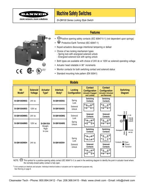
<strong>Machine</strong> <strong>Safety</strong> <strong>Switches</strong><br />
<strong>SI</strong>-<strong>QM100</strong> <strong>Series</strong> <strong>Locking</strong> <strong>Style</strong> Switch<br />
Features<br />
• Positive opening safety contacts (IEC 60947-5-1) (not dependent upon springs)<br />
• Protective Earth Terminal (IEC 60947-1)<br />
• Keyed actuators discourage intentional tampering or defeat<br />
• Choice of two locking mechanism types:<br />
- Spring lock with energized solenoid unlock<br />
- Energized solenoid lock with spring unlock<br />
• Both types are available with choice of 24V dc or 120V ac solenoid operating voltage<br />
• Actuator head rotatable in 90° increments<br />
• Monitor contacts for both switching contact and solenoid status<br />
• Standard mounting hole pattern (EN 50041)<br />
Interlock<br />
Body †<br />
<strong>SI</strong>-<strong>QM100</strong>DSG<br />
<strong>SI</strong>-<strong>QM100</strong>AMSG 120V ac <strong>SI</strong>-<strong>QM100</strong>ASG<br />
Models<br />
<strong>Locking</strong><br />
Configuration<br />
Spring<br />
Lock<br />
Solenoid<br />
Unlock<br />
<strong>SI</strong>-<strong>QM100</strong>DMMG 24V dc <strong>SI</strong>-<strong>QM100</strong>DMG Solenoid<br />
Lock<br />
<strong>SI</strong>-<strong>QM100</strong>AMMG 120V ac <strong>SI</strong>-QM-SSA<br />
Straight,<br />
Rigid<br />
In-Line<br />
<strong>SI</strong>-<strong>QM100</strong>AMG<br />
Spring<br />
Unlock<br />
<strong>SI</strong>-<strong>QM100</strong>DMSH 24V dc <strong>SI</strong>-<strong>QM100</strong>DSH<br />
Spring<br />
Lock<br />
Solenoid<br />
Unlock<br />
Contact<br />
Configuration<br />
(Actuator Engaged<br />
and Locked)<br />
Switching<br />
Contacts<br />
21 22<br />
13 14<br />
Solenoid<br />
Contacts<br />
31 32<br />
43 44<br />
Switching<br />
Contacts<br />
21 22<br />
11 12<br />
Solenoid<br />
Contacts<br />
31 32<br />
43 44<br />
Contact<br />
Configuration<br />
(Actuator Unlocked<br />
and Removed)<br />
Switching<br />
Contacts<br />
21 22<br />
13 14<br />
Solenoid<br />
Contacts<br />
31 32<br />
43 44<br />
Switching<br />
Contacts<br />
21 22<br />
11 12<br />
Solenoid<br />
Contacts<br />
31 32<br />
43 44<br />
Switching<br />
Diagram<br />
0 (0)<br />
10 (0.39)<br />
11 (0.43)<br />
12 (0.47)<br />
Contacts: Open<br />
Closed<br />
Transition<br />
NOTE: This symbol for a positive-opening safety contact (IEC 60947-5-1) is used in the switching diagram to identify the point in actuator travel where<br />
the normally-closed safety contact is fully open.<br />
† A kit contains an interlock and actuator. Individual interlock bodies or actuators are for replacement purposes only.<br />
See Warning on page 8.<br />
Engaged<br />
Disengaged<br />
Clearwater Tech - Phone: 800.894.0412 - Fax: 208.368.0415 - Web: www.clrwtr.com - Email: info@clrwtr.com<br />
21-22<br />
13-14<br />
<strong>Safety</strong><br />
Monitor<br />
41 (1.61)<br />
mm (in)
<strong>Machine</strong> <strong>Safety</strong> Switch – <strong>SI</strong>-<strong>QM100</strong> <strong>Series</strong>, <strong>Locking</strong> <strong>Style</strong><br />
Important Information Regarding the Use of <strong>Safety</strong> <strong>Switches</strong><br />
In the United States, the functions that <strong>Banner</strong> safety switches are intended to perform are regulated by the Occupational <strong>Safety</strong> and Health<br />
Administration (OSHA). Whether or not any particular safety switch installation meets all applicable OSHA requirements depends upon factors<br />
that are beyond the control of <strong>Banner</strong> Engineering Corp. These factors include the details of how the safety switches are applied, installed, wired,<br />
operated, and maintained.<br />
<strong>Banner</strong> Engineering Corp. has attempted to provide complete application, installation, operation, and maintenance instructions. This information is<br />
found in the instruction manual packaged with each safety switch. In addition, we suggest that any questions regarding the use or installation of<br />
safety switches be directed to the factory applications department at the telephone numbers or address shown below.<br />
<strong>Banner</strong> Engineering Corp. recommends that safety switches be applied according to the guidelines set forth in international (ISO/IEC) standards<br />
listed below. Specifically, <strong>Banner</strong> Engineering Corp. recommends application of safety switches in a configuration which meets safety category 4,<br />
per ISO 13849-1 (EN954-1).<br />
In addition, the user of <strong>Banner</strong> safety switches has the responsibility to ensure that all local, state, and national laws, rules, codes, and regulations<br />
relating to the use of <strong>Banner</strong> safety switches in any particular application are satisfied. Extreme care is urged that all legal requirements have been<br />
met and that all installations and maintenance instructions are followed.<br />
U.S. Regulations Applicable to Use of <strong>Banner</strong> <strong>Safety</strong> <strong>Switches</strong><br />
Application Assistance<br />
Toll Free: 1-888-3-SENSOR (1-888-373-6767)<br />
Email: sensors@bannerengineering.com<br />
Address: 9714 Tenth Avenue North<br />
Minneapolis, MN 55441<br />
OSHA Code of Federal Regulations: Title 29, Parts 1900 to 1910<br />
Available from: Superintendent of Documents<br />
Government Printing Office<br />
P.O. Box 371954<br />
Pittsburgh, PA 15250-7954<br />
Tel: 202-512-1800<br />
U.S. Standards Applicable to Use of <strong>Banner</strong> <strong>Safety</strong> <strong>Switches</strong><br />
AN<strong>SI</strong> B11 “ Standards for Construction, Care, and Use of <strong>Machine</strong> Tools”<br />
Available from: <strong>Safety</strong> Director<br />
AMT—The Association for Manufacturing Technology<br />
7901 Westpark Drive<br />
McLean, VA 22102<br />
Tel: 703-893-2900<br />
Applicable European and International Standards<br />
ISO 12100-1/-2<br />
(EN292-1/-2)<br />
“<strong>Safety</strong> of <strong>Machine</strong>ry—Basic Concepts, General Principles for Design”<br />
ISO 13852 (EN 294) “<strong>Safety</strong> of <strong>Machine</strong>ry—<strong>Safety</strong> Distances to Prevent Danger Zones Being Reached by the Upper Limbs”<br />
ISO 13853 (EN 811) “<strong>Safety</strong> of <strong>Machine</strong>ry—<strong>Safety</strong> Distances to Prevent Danger Zones Being Reached by the Lower Limbs”<br />
ISO 13849-1 (EN 954-1) “<strong>Safety</strong> of <strong>Machine</strong>ry—<strong>Safety</strong> Related Parts of Control Systems”<br />
ISO 13855 (EN 999) “ <strong>Safety</strong> of <strong>Machine</strong>ry—The Positioning of Protective Equipment in Respect to Approach Speeds of Parts of the<br />
Human Body”<br />
ISO 14119 (EN 1088) “<strong>Safety</strong> of <strong>Machine</strong>ry—Interlocking Devices Associated with Guards—Principles for Design and Selection”<br />
IEC/EN 60204-1 “<strong>Safety</strong> of <strong>Machine</strong>ry—Electrical Equipment of <strong>Machine</strong>s”<br />
IEC/EN 60947-5-1 “Low Voltage Switchgear—Electromechanical Control Circuit Devices”<br />
Available from: Global Engineering Documents<br />
15 Inverness Way East<br />
Englewood, CO 80112-5704<br />
Phone: 1-800-854-7179<br />
Fax: 303-397-2740<br />
Clearwater Tech - Phone: 800.894.0412 - Fax: 208.368.0415 - Web: www.clrwtr.com - Email: info@clrwtr.com
Spring Lock,<br />
Solenoid Unlock<br />
Spring Unlock,<br />
Solenoid Lock<br />
<strong>Machine</strong> <strong>Safety</strong> Switch – <strong>SI</strong>-<strong>QM100</strong> <strong>Series</strong>, <strong>Locking</strong> <strong>Style</strong><br />
Overview<br />
Spring Lock, Solenoid Unlock (Models <strong>SI</strong>-<strong>QM100</strong>DMSG and <strong>SI</strong>-<strong>QM100</strong>AMSG)<br />
The actuator is mechanically locked when it is fully inserted into the actuator head. The<br />
actuator is unlocked by applying voltage to the solenoid.<br />
Solenoid Lock, Spring Unlock (Models <strong>SI</strong>-<strong>QM100</strong>DMMG and <strong>SI</strong>-<strong>QM100</strong>AMMG)<br />
The fully inserted actuator is locked when voltage is applied to the solenoid. The actuator is<br />
unlocked when voltage is removed from the solenoid.<br />
Mechanical Installation<br />
The actuator head may be rotated, if desired, to any of four 90 degree positions. To reposition<br />
the actuator head, unscrew the four mounting bolts, turn the head to the desired position, and<br />
re-tighten the bolts (see the drawing at left).<br />
IMPORTANT: Be certain that the actuator is fully engaged before removing the actuator head<br />
screws during the rotation process.<br />
All mounting hardware is supplied by the user. The fasteners must be of sufficient strength to<br />
avoid incidental breakage. Use of permanent fasteners or locking hardware is recommended<br />
to prevent loosening or displacement of the actuator and switch body.<br />
The mounting holes in the switch body accept M5 (#10) screws. There are three holes on<br />
a standard limit switch mounting pattern of 30 x 60 mm. The two mounting holes on the<br />
actuator are spaced 20 mm apart. The grommet and sleeve design allows a small amount<br />
of movement (i. e., misalignment) when the actuator engages the switch body. The sleeves<br />
accept M4.5 (#8) screws.<br />
Position the switch, with its actuator fully engaged, in the mounting location and mark the<br />
mounting holes. Fasten the switch body and the actuator in place. The non-adjustable in-line<br />
actuator includes floating sleeves in the mounting holes to allow some forgiveness for switchto-actuator<br />
alignment. Take care to not over-tighten the actuator fasteners so as to allow this<br />
movement. After the mounting hardware is secure, check the actuator/switch engagement for<br />
misalignment and binding.<br />
IMPORTANT: A safety switch must be installed in a manner which discourages<br />
tampering or defeat. Mount each switch to prevent bypassing of the switching function<br />
at the terminal chamber. A switch and its actuator must never be used as a mechanical<br />
stop.<br />
Clearwater Tech - Phone: 800.894.0412 - Fax: 208.368.0415 - Web: www.clrwtr.com - Email: info@clrwtr.com
<strong>Machine</strong> <strong>Safety</strong> Switch – <strong>SI</strong>-<strong>QM100</strong> <strong>Series</strong>, <strong>Locking</strong> <strong>Style</strong><br />
Manual Release for Spring Lock Models<br />
Models with solenoid unlock may be manually unlocked by depressing the button which is<br />
located beneath the large hex cover screw on the switch body (see Figure 1). The manual<br />
release button is only for emergency use when there has been system power loss or solenoid<br />
failure. Access to the manual release button must be restricted by installing a security<br />
wire between the hole in the hex cover and the hole in the screw immediately above the<br />
hex cover (see Figure 1).<br />
Security Wire<br />
Access to<br />
Manual<br />
Release<br />
(see text)<br />
Figure 1. Manual spring lock release<br />
Electrical Installation<br />
Access to the Wiring Chamber<br />
The wiring chamber is accessed via a cover plate which is held in place by four screws. A<br />
conduit adapter is supplied to convert the M20 x 1.5 thread to ½" x 14 NPT. An accessory<br />
cable gland which fits the M20 x 1.5 thread is available (see page 10).<br />
Connection to a <strong>Machine</strong><br />
Four contacts are offered. Two are safety contacts which must be wired in series, and the<br />
other two are considered monitoring contacts which may be used, if desired.<br />
The contact between terminals 11 and 12 or 21 and 22 is a safety contact which is closed<br />
(i.e., it conducts) when the actuator is engaged. The contact between terminals 13 and 14 is<br />
the associated actuator monitoring contact.<br />
The contact between terminals 31 and 32 is a safety contact which is closed when the<br />
solenoid is in its locking state. The contact between terminals 43 and 44 is the associated<br />
solenoid monitoring contact.<br />
See the switching diagrams on page 1 for contact state information.<br />
As illustrated in Figure 2, the normally-closed safety contact (i.e., safety contacts that are<br />
closed when the actuator is engaged and the solenoid is in its locking state) from each of<br />
two safety switches per interlock guard must connect to a 2-channel safety module or<br />
safety interface in order to achieve a control reliable interface to the master stop control<br />
elements of a machine. Examples of appropriate safety modules include<br />
2-channel emergency stop (E-stop) safety modules and gate monitor safety modules. Refer to<br />
Figures 3 and 4 for terminal connections.<br />
WARNING . . .<br />
It must not be possible for personnel to reach<br />
any hazard point through an opened guard (or<br />
any opening) before hazardous machine motion<br />
has completely stopped. Please reference<br />
OSHA CFR 1910.217 and AN<strong>SI</strong> B11 standards<br />
(see page 2) for information on determining<br />
safety distances and safe opening sizes for your<br />
guarding devices.<br />
CAUTION . . . Auxiliary<br />
Electrical Installation<br />
Two safety switches must be used for each<br />
interlock guard to achieve control reliability<br />
or <strong>Safety</strong> Category (per ISO 1 8 9-1,<br />
EN 95 -1) of a machine stop circuit. Use of<br />
only one safety switch per interlock guard is<br />
not recommended.<br />
In addition, normally-closed safety contacts<br />
from each of the two safety switches should be<br />
connected to the two separate inputs of a<br />
2-channel safety module or safety interface, as<br />
illustrated in Figure 2. This is required to provide<br />
monitoring for safety switch contact failure,<br />
and to provide the necessary reset routine, as<br />
required by IEC 60204-1 and NFPA 79 machine<br />
safety standards.<br />
WARNING . . . <strong>Series</strong><br />
Connection of <strong>Safety</strong><br />
Interlock <strong>Switches</strong><br />
Monitoring multiple guards with a series<br />
connection of multiple safety interlock<br />
switches is not a <strong>Safety</strong> Category<br />
Application (per ISO 1 8 9-1, EN 95 -1).<br />
A single failure may be masked or not<br />
detected at all. When such a configuration<br />
is used, procedures must be performed<br />
regularly to verify proper operation of each<br />
switch.<br />
Clearwater Tech - Phone: 800.894.0412 - Fax: 208.368.0415 - Web: www.clrwtr.com - Email: info@clrwtr.com
<strong>Safety</strong> Switch #1 <strong>Safety</strong> Switch #2<br />
32<br />
31<br />
22<br />
21<br />
Figure . Connect two redundant safety<br />
switches per interlock guard to an<br />
appropriate -channel input safety<br />
module.<br />
Solenoid<br />
Voltage<br />
Input<br />
Channel<br />
#1<br />
2-channel <strong>Safety</strong> Module<br />
E1<br />
E2<br />
13<br />
Input<br />
Channel<br />
#2<br />
(2-channel E-stop Module<br />
2-channel Gate Monitor Module, etc.)<br />
43 44<br />
14 21 22 31<br />
Figure . Switch electrical connections<br />
— models <strong>SI</strong>-<strong>QM100</strong>..G<br />
32<br />
31<br />
22<br />
21<br />
32<br />
Single gate<br />
or guard<br />
NOTE: Refer to the installation instructions<br />
provided with the safety module for<br />
information regarding the interface of<br />
the safety module to the machine stop<br />
control elements.<br />
Solenoid<br />
Voltage<br />
E1<br />
E2<br />
11<br />
43 44<br />
12 21 22 31<br />
Figure . Switch electrical connections<br />
— models <strong>SI</strong>-<strong>QM100</strong>..DSH<br />
32<br />
<strong>Machine</strong> <strong>Safety</strong> Switch – <strong>SI</strong>-<strong>QM100</strong> <strong>Series</strong>, <strong>Locking</strong> <strong>Style</strong><br />
Two functions of the safety module or safety interface are:<br />
1. to provide a means of monitoring the contacts of both safety switches for contact failure,<br />
and to prevent the machine from restarting if either switch fails; and<br />
2. to provide a reset routine after closing the guard and returning the safety contacts to their<br />
closed position. This prevents the controlled machinery from restarting by simply reinserting<br />
the safety switch actuators. This necessary reset function is required by AN<strong>SI</strong> B11 and<br />
NFPA 79 machine safety standards.<br />
Use only positively driven, normally closed safety contacts from each switch for connection<br />
to the safety module. The normally open contacts may be used for control functions that are<br />
not safety-related. A typical use is to communicate with a process controller. Refer to the<br />
installation instructions provided with the safety modules for more information regarding the<br />
interface of the safety module to the machine stop control elements.<br />
Periodic Checks<br />
<strong>Safety</strong> switches should be checked at each shift change or machine setup by a designated<br />
person (see below) for:<br />
1. Breakage of the switch body or actuator,<br />
2. Good alignment and full engagement of the actuator with the receptor,<br />
3. Confirmation that the safety switch is not being used as an end stop,<br />
4. Loosening of the switch or actuator mounting hardware, and<br />
5. Verification that it is not possible to reach any hazard point through an opened guard (or<br />
any opening) before hazardous machine motion has completely stopped.<br />
In addition, a qualified person should check for the following on a periodic schedule,<br />
determined by the user, based upon the severity of the operating environment and the<br />
frequency of switch actuations:<br />
1. Check the wiring chamber for signs of contamination.<br />
2. Check the contacts for signs of deterioration or damage.<br />
3. Inspect the electrical wiring for continuity and damage.<br />
4. Verify that wiring conforms to the instructions on pages 4 and 5 of this data sheet.<br />
A designated person is identified in writing by the employer as being appropriately trained to<br />
perform a specified checkout procedure. A qualified person possesses a recognized degree or<br />
certificate or has extensive knowledge, training, and experience to be able to solve problems<br />
relating to the safety switch installation.<br />
Clearwater Tech - Phone: 800.894.0412 - Fax: 208.368.0415 - Web: www.clrwtr.com - Email: info@clrwtr.com
<strong>Machine</strong> <strong>Safety</strong> Switch – <strong>SI</strong>-<strong>QM100</strong> <strong>Series</strong>, <strong>Locking</strong> <strong>Style</strong><br />
Repairs<br />
Do not attempt any repairs to the switch. It contains no field-replaceable components.<br />
Return the switch to the factory for warranty repair or replacement.<br />
If it ever becomes necessary to return a switch to the factory, please do the following:<br />
1. Contact the <strong>Banner</strong> applications engineering department at the number or address listed<br />
on the back cover. They will attempt to troubleshoot the system from your description of<br />
the problem. If they conclude that a component is defective, they will issue an RMA (Return<br />
Merchandise Authorization) number for your paperwork, and give you the proper shipping<br />
address.<br />
2. Pack the switch carefully. Damage which occurs in shipping is not covered by warranty.<br />
Specifications<br />
Contact Rating 4A @ 250V ac max.<br />
2.5 kV max. transient tolerance<br />
NEMA A300 P300<br />
European Rating Utilization categories: AC15 and DC13 (IEC 60947-5-1)<br />
<strong>Switches</strong> with 1 and contact pairs:<br />
Ui = 250V ac<br />
Ith = 10A<br />
Ue V<br />
40-60 Hz<br />
Ie/AC-15 A<br />
Ie/AC-13 A<br />
24 4 3<br />
110 4 0.7<br />
230 4 0.3<br />
Contact Material Silver-nickel alloy<br />
Solenoid Power<br />
Consumption<br />
5.2 W<br />
Maximum Actuator Speed 1.5 m/second (5'/second)<br />
Minimum Actuator<br />
In-line actuators: 400 mm (16")<br />
Engagement Radius<br />
Flexible actuators: 150 mm (6")<br />
Actuator Extraction Force 1000 Newtons (220 lbf) when locked<br />
Short Circuit Protection 6 amp Slow Blow, 10 amp Fast Blow. Recommended external fusing or overload protection.<br />
Mechanical Life 1 million operations<br />
Wire Connections Screw terminals with pressure plates accept the following wire sizes—<br />
16 AWG (1.5 mm2 ) max. solid; 14 AWG (2.5 mm2 ) max. stranded, 18 AWG (1 mm2 ) when using all 11 terminals<br />
Cable Entry M20 x 1.5 threaded entrance. Adapter supplied to convert M20 x 1.5 to ½" - 14 NPT threaded entrance.<br />
Construction Aluminum die-cast housing<br />
Environmental Rating IEC IP67<br />
Operating Conditions Temperature: –30° to +60° C (–22° to +140° F)<br />
Weight 0.81 kg (1.79 lb)<br />
Application Notes When rotating the actuator head, the actuator MUST BE FULLY ENGAGED.<br />
When using a model with solenoid locking, the lock mechanism will disengage upon solenoid power failure.<br />
Certifications<br />
Clearwater Tech - Phone: 800.894.0412 - Fax: 208.368.0415 - Web: www.clrwtr.com - Email: info@clrwtr.com
6.5 mm<br />
(0.26")<br />
20.0 mm<br />
(0.79")<br />
50.0 mm<br />
(1.97")<br />
45.0 mm<br />
(1.77")<br />
17.5 mm<br />
(0.69")<br />
9.8 mm<br />
(0.39")<br />
Size Model<br />
M20 x 1.5<br />
Metal<br />
Description Model*<br />
½"-14 NPT Metal<br />
Conduit Adaptor<br />
100.0 mm<br />
(3.94")<br />
M20 x 1.5<br />
1/2"-14 NPT<br />
Adapter is Supplied<br />
<strong>Machine</strong> <strong>Safety</strong> Switch – <strong>SI</strong>-<strong>QM100</strong> <strong>Series</strong>, <strong>Locking</strong> <strong>Style</strong><br />
41.3 mm<br />
(1.63") 5.2 mm<br />
(0.20") (x3)<br />
22.0 mm<br />
(0.87")<br />
30.0 mm<br />
(1.18")<br />
2.0 mm<br />
(0.08")<br />
Used with<br />
Switch Models<br />
<strong>SI</strong>-QM-CGM 0 All<br />
*NOTE: One conduit adapter is supplied with each switch.<br />
Switch Dimensions<br />
Used with<br />
Switch Models<br />
<strong>SI</strong>-QM-M 0 All<br />
Dimensions<br />
30.0 mm<br />
(1.18")<br />
Access to<br />
Manual Release<br />
(<strong>SI</strong>-<strong>QM100</strong>..MSG<br />
<strong>Series</strong> only)<br />
90.0 mm<br />
(3.54")<br />
20.0 mm<br />
(0.79")<br />
Accessories<br />
Cable Glands<br />
For Cable<br />
Diameters<br />
≥ 80 mm<br />
(3.1")<br />
ø 4.8 mm (2)<br />
2.5 mm<br />
(0.10")<br />
8.0 mm<br />
(0.31")<br />
(x2)<br />
5.0 to 12.0 mm<br />
(0.20" to 0.47") M20 x 1.5<br />
Replacement Parts<br />
Thread<br />
Conversion<br />
M20 x 1.5<br />
to<br />
½"-14 NPT<br />
3.0 mm<br />
(0.12")<br />
36.8 mm<br />
(1.45")<br />
32.0 mm<br />
60.0 (1.26") mm<br />
(2.36")<br />
116.0 mm<br />
(4.56")<br />
ø 5.2 mm<br />
(0.20") 34 mm<br />
5.2 mm (1.3")<br />
(0.20")<br />
30.0 mm<br />
(4)<br />
(1.18")<br />
Pg 13.5<br />
1/2"-14 NPSM<br />
Adapter is Supplied<br />
M20 x 1.5<br />
40.0 mm<br />
(1.56")<br />
35.5 mm<br />
(1.40")<br />
23.0 mm<br />
(0.91")<br />
12.0 mm<br />
(0.47")<br />
60.0 mm<br />
(2.36")<br />
2.0 mm<br />
(0.08")<br />
Dimensions<br />
Actuator Dimensions<br />
20.0 mm<br />
(0.79")<br />
ø 4.8 mm<br />
(2 Holes)<br />
Dimensions<br />
33.0 mm<br />
(1.30")<br />
80.0 mm<br />
(3.13")<br />
37.5 mm<br />
(1.48")<br />
1/2"-14 NPT<br />
Internal Thread<br />
80.0 mm<br />
(3.13")<br />
74.5 mm<br />
(2.93")<br />
24.0 mm<br />
(0.94")<br />
24.0 mm<br />
(0.94")<br />
15 mm<br />
(0.59")<br />
7.5 mm<br />
(0.30")<br />
Clearwater Tech - Phone: 800.894.0412 - Fax: 208.368.0415 - Web: www.clrwtr.com - Email: info@clrwtr.com<br />
O-ring<br />
36.8 mm<br />
(1.45")
<strong>Machine</strong> <strong>Safety</strong> Switch – <strong>SI</strong>-<strong>QM100</strong> <strong>Series</strong>, <strong>Locking</strong> <strong>Style</strong><br />
WARNING . . . Spare Actuators<br />
Spare actuators must NEVER be used to bypass or otherwise defeat the protective function of a safety switch. To do so may create an unsafe<br />
situation which could lead to serious injury or death.<br />
P/N 49374 rev. E<br />
Description Model<br />
Accessory Actuators<br />
Used with<br />
Switch Models<br />
In-line Flexible Metal <strong>SI</strong>-QM-SMFA All<br />
Rigid in-line metal actuator<br />
used for doors or covers.<br />
Slide-bolt design for use<br />
in heavy-duty applications<br />
where alignment is difficult<br />
to maintain.<br />
<strong>SI</strong>-QM-SB All<br />
Dimensions<br />
40 mm<br />
(1.6")<br />
50 mm<br />
(2.0")<br />
WARRANTY: <strong>Banner</strong> Engineering Corp. warrants its products to be free from defects for one year. <strong>Banner</strong> Engineering<br />
Corp. will repair or replace, free of charge, any product of its manufacture found to be defective at the time it is returned<br />
to the factory during the warranty period. This warranty does not cover damage or liability for the improper application of<br />
<strong>Banner</strong> products. This warranty is in lieu of any other warranty either expressed or implied.<br />
9.6 mm<br />
(0.40")<br />
20.0 mm<br />
(0.80")<br />
40.0 mm<br />
(1.60")<br />
4x Ø5.5 mm (0.20")<br />
3.0 mm<br />
(0.13")<br />
20.0 mm<br />
(0.80")<br />
81 mm<br />
(3.2")<br />
41 mm<br />
(1.6")<br />
42.0 mm<br />
(1.70")<br />
100.0 mm<br />
(3.9")<br />
140.0 mm<br />
(5.50")<br />
29 mm<br />
(1.1")<br />
ø 5.5 mm<br />
(0.22")<br />
38.0 mm<br />
(1.50")<br />
C L<br />
59.0 mm<br />
(2.30")<br />
31.0 mm<br />
(1.20")<br />
Ø8 mm hole<br />
for locking bolt<br />
in the open<br />
position<br />
Clearwater Tech - Phone: 800.894.0412 - Fax: 208.368.0415 - Web: www.clrwtr.com - Email: info@clrwtr.com<br />
47.0 mm<br />
(1.90")