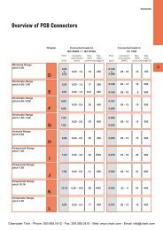
Banner SI-QM100 Series Locking Style Machine Safety Switches
Banner SI-QM100 Series Locking Style Machine Safety Switches
Banner SI-QM100 Series Locking Style Machine Safety Switches

Create successful ePaper yourself
Turn your PDF publications into a flip-book with our unique Google optimized e-Paper software.
Kit<br />
Model †<br />
Solenoid<br />
Voltage<br />
<strong>SI</strong>-<strong>QM100</strong>DMSG 24V dc<br />
Actuator<br />
Type †<br />
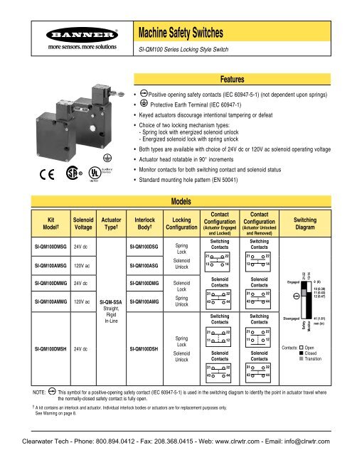
<strong>Machine</strong> <strong>Safety</strong> <strong>Switches</strong><br />
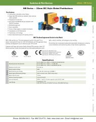
<strong>SI</strong>-<strong>QM100</strong> <strong>Series</strong> <strong>Locking</strong> <strong>Style</strong> Switch<br />
Features<br />
• Positive opening safety contacts (IEC 60947-5-1) (not dependent upon springs)<br />
• Protective Earth Terminal (IEC 60947-1)<br />
• Keyed actuators discourage intentional tampering or defeat<br />
• Choice of two locking mechanism types:<br />
- Spring lock with energized solenoid unlock<br />
- Energized solenoid lock with spring unlock<br />
• Both types are available with choice of 24V dc or 120V ac solenoid operating voltage<br />
• Actuator head rotatable in 90° increments<br />
• Monitor contacts for both switching contact and solenoid status<br />
• Standard mounting hole pattern (EN 50041)<br />
Interlock<br />
Body †<br />
<strong>SI</strong>-<strong>QM100</strong>DSG<br />
<strong>SI</strong>-<strong>QM100</strong>AMSG 120V ac <strong>SI</strong>-<strong>QM100</strong>ASG<br />
Models<br />
<strong>Locking</strong><br />
Configuration<br />
Spring<br />
Lock<br />
Solenoid<br />
Unlock<br />
<strong>SI</strong>-<strong>QM100</strong>DMMG 24V dc <strong>SI</strong>-<strong>QM100</strong>DMG Solenoid<br />
Lock<br />
<strong>SI</strong>-<strong>QM100</strong>AMMG 120V ac <strong>SI</strong>-QM-SSA<br />
Straight,<br />
Rigid<br />
In-Line<br />
<strong>SI</strong>-<strong>QM100</strong>AMG<br />
Spring<br />
Unlock<br />
<strong>SI</strong>-<strong>QM100</strong>DMSH 24V dc <strong>SI</strong>-<strong>QM100</strong>DSH<br />
Spring<br />
Lock<br />
Solenoid<br />
Unlock<br />
Contact<br />
Configuration<br />
(Actuator Engaged<br />
and Locked)<br />
Switching<br />
Contacts<br />
21 22<br />
13 14<br />
Solenoid<br />
Contacts<br />
31 32<br />
43 44<br />
Switching<br />
Contacts<br />
21 22<br />
11 12<br />
Solenoid<br />
Contacts<br />
31 32<br />
43 44<br />
Contact<br />
Configuration<br />
(Actuator Unlocked<br />
and Removed)<br />
Switching<br />
Contacts<br />
21 22<br />
13 14<br />
Solenoid<br />
Contacts<br />
31 32<br />
43 44<br />
Switching<br />
Contacts<br />
21 22<br />
11 12<br />
Solenoid<br />
Contacts<br />
31 32<br />
43 44<br />
Switching<br />
Diagram<br />
0 (0)<br />
10 (0.39)<br />
11 (0.43)<br />
12 (0.47)<br />
Contacts: Open<br />
Closed<br />
Transition<br />
NOTE: This symbol for a positive-opening safety contact (IEC 60947-5-1) is used in the switching diagram to identify the point in actuator travel where<br />
the normally-closed safety contact is fully open.<br />
† A kit contains an interlock and actuator. Individual interlock bodies or actuators are for replacement purposes only.<br />
See Warning on page 8.<br />
Engaged<br />
Disengaged<br />
Clearwater Tech - Phone: 800.894.0412 - Fax: 208.368.0415 - Web: www.clrwtr.com - Email: info@clrwtr.com<br />
21-22<br />
13-14<br />
<strong>Safety</strong><br />
Monitor<br />
41 (1.61)<br />
mm (in)
<strong>Machine</strong> <strong>Safety</strong> Switch – <strong>SI</strong>-<strong>QM100</strong> <strong>Series</strong>, <strong>Locking</strong> <strong>Style</strong><br />
Important Information Regarding the Use of <strong>Safety</strong> <strong>Switches</strong><br />
In the United States, the functions that <strong>Banner</strong> safety switches are intended to perform are regulated by the Occupational <strong>Safety</strong> and Health<br />
Administration (OSHA). Whether or not any particular safety switch installation meets all applicable OSHA requirements depends upon factors<br />
that are beyond the control of <strong>Banner</strong> Engineering Corp. These factors include the details of how the safety switches are applied, installed, wired,<br />
operated, and maintained.<br />
<strong>Banner</strong> Engineering Corp. has attempted to provide complete application, installation, operation, and maintenance instructions. This information is<br />
found in the instruction manual packaged with each safety switch. In addition, we suggest that any questions regarding the use or installation of<br />
safety switches be directed to the factory applications department at the telephone numbers or address shown below.<br />
<strong>Banner</strong> Engineering Corp. recommends that safety switches be applied according to the guidelines set forth in international (ISO/IEC) standards<br />
listed below. Specifically, <strong>Banner</strong> Engineering Corp. recommends application of safety switches in a configuration which meets safety category 4,<br />
per ISO 13849-1 (EN954-1).<br />
In addition, the user of <strong>Banner</strong> safety switches has the responsibility to ensure that all local, state, and national laws, rules, codes, and regulations<br />
relating to the use of <strong>Banner</strong> safety switches in any particular application are satisfied. Extreme care is urged that all legal requirements have been<br />
met and that all installations and maintenance instructions are followed.<br />
U.S. Regulations Applicable to Use of <strong>Banner</strong> <strong>Safety</strong> <strong>Switches</strong><br />
Application Assistance<br />
Toll Free: 1-888-3-SENSOR (1-888-373-6767)<br />
Email: sensors@bannerengineering.com<br />
Address: 9714 Tenth Avenue North<br />
Minneapolis, MN 55441<br />
OSHA Code of Federal Regulations: Title 29, Parts 1900 to 1910<br />
Available from: Superintendent of Documents<br />
Government Printing Office<br />
P.O. Box 371954<br />
Pittsburgh, PA 15250-7954<br />
Tel: 202-512-1800<br />
U.S. Standards Applicable to Use of <strong>Banner</strong> <strong>Safety</strong> <strong>Switches</strong><br />
AN<strong>SI</strong> B11 “ Standards for Construction, Care, and Use of <strong>Machine</strong> Tools”<br />
Available from: <strong>Safety</strong> Director<br />
AMT—The Association for Manufacturing Technology<br />
7901 Westpark Drive<br />
McLean, VA 22102<br />
Tel: 703-893-2900<br />
Applicable European and International Standards<br />
ISO 12100-1/-2<br />
(EN292-1/-2)<br />
“<strong>Safety</strong> of <strong>Machine</strong>ry—Basic Concepts, General Principles for Design”<br />
ISO 13852 (EN 294) “<strong>Safety</strong> of <strong>Machine</strong>ry—<strong>Safety</strong> Distances to Prevent Danger Zones Being Reached by the Upper Limbs”<br />
ISO 13853 (EN 811) “<strong>Safety</strong> of <strong>Machine</strong>ry—<strong>Safety</strong> Distances to Prevent Danger Zones Being Reached by the Lower Limbs”<br />
ISO 13849-1 (EN 954-1) “<strong>Safety</strong> of <strong>Machine</strong>ry—<strong>Safety</strong> Related Parts of Control Systems”<br />
ISO 13855 (EN 999) “ <strong>Safety</strong> of <strong>Machine</strong>ry—The Positioning of Protective Equipment in Respect to Approach Speeds of Parts of the<br />
Human Body”<br />
ISO 14119 (EN 1088) “<strong>Safety</strong> of <strong>Machine</strong>ry—Interlocking Devices Associated with Guards—Principles for Design and Selection”<br />
IEC/EN 60204-1 “<strong>Safety</strong> of <strong>Machine</strong>ry—Electrical Equipment of <strong>Machine</strong>s”<br />
IEC/EN 60947-5-1 “Low Voltage Switchgear—Electromechanical Control Circuit Devices”<br />
Available from: Global Engineering Documents<br />
15 Inverness Way East<br />
Englewood, CO 80112-5704<br />
Phone: 1-800-854-7179<br />
Fax: 303-397-2740<br />
Clearwater Tech - Phone: 800.894.0412 - Fax: 208.368.0415 - Web: www.clrwtr.com - Email: info@clrwtr.com
Spring Lock,<br />
Solenoid Unlock<br />
Spring Unlock,<br />
Solenoid Lock<br />
<strong>Machine</strong> <strong>Safety</strong> Switch – <strong>SI</strong>-<strong>QM100</strong> <strong>Series</strong>, <strong>Locking</strong> <strong>Style</strong><br />
Overview<br />
Spring Lock, Solenoid Unlock (Models <strong>SI</strong>-<strong>QM100</strong>DMSG and <strong>SI</strong>-<strong>QM100</strong>AMSG)<br />
The actuator is mechanically locked when it is fully inserted into the actuator head. The<br />
actuator is unlocked by applying voltage to the solenoid.<br />
Solenoid Lock, Spring Unlock (Models <strong>SI</strong>-<strong>QM100</strong>DMMG and <strong>SI</strong>-<strong>QM100</strong>AMMG)<br />
The fully inserted actuator is locked when voltage is applied to the solenoid. The actuator is<br />
unlocked when voltage is removed from the solenoid.<br />
Mechanical Installation<br />
The actuator head may be rotated, if desired, to any of four 90 degree positions. To reposition<br />
the actuator head, unscrew the four mounting bolts, turn the head to the desired position, and<br />
re-tighten the bolts (see the drawing at left).<br />
IMPORTANT: Be certain that the actuator is fully engaged before removing the actuator head<br />
screws during the rotation process.<br />
All mounting hardware is supplied by the user. The fasteners must be of sufficient strength to<br />
avoid incidental breakage. Use of permanent fasteners or locking hardware is recommended<br />
to prevent loosening or displacement of the actuator and switch body.<br />
The mounting holes in the switch body accept M5 (#10) screws. There are three holes on<br />
a standard limit switch mounting pattern of 30 x 60 mm. The two mounting holes on the<br />
actuator are spaced 20 mm apart. The grommet and sleeve design allows a small amount<br />
of movement (i. e., misalignment) when the actuator engages the switch body. The sleeves<br />
accept M4.5 (#8) screws.<br />
Position the switch, with its actuator fully engaged, in the mounting location and mark the<br />
mounting holes. Fasten the switch body and the actuator in place. The non-adjustable in-line<br />
actuator includes floating sleeves in the mounting holes to allow some forgiveness for switchto-actuator<br />
alignment. Take care to not over-tighten the actuator fasteners so as to allow this<br />
movement. After the mounting hardware is secure, check the actuator/switch engagement for<br />
misalignment and binding.<br />
IMPORTANT: A safety switch must be installed in a manner which discourages<br />
tampering or defeat. Mount each switch to prevent bypassing of the switching function<br />
at the terminal chamber. A switch and its actuator must never be used as a mechanical<br />
stop.<br />
Clearwater Tech - Phone: 800.894.0412 - Fax: 208.368.0415 - Web: www.clrwtr.com - Email: info@clrwtr.com
<strong>Machine</strong> <strong>Safety</strong> Switch – <strong>SI</strong>-<strong>QM100</strong> <strong>Series</strong>, <strong>Locking</strong> <strong>Style</strong><br />
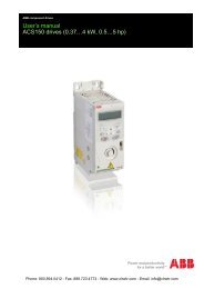
Manual Release for Spring Lock Models<br />
Models with solenoid unlock may be manually unlocked by depressing the button which is<br />
located beneath the large hex cover screw on the switch body (see Figure 1). The manual<br />
release button is only for emergency use when there has been system power loss or solenoid<br />
failure. Access to the manual release button must be restricted by installing a security<br />
wire between the hole in the hex cover and the hole in the screw immediately above the<br />
hex cover (see Figure 1).<br />
Security Wire<br />
Access to<br />
Manual<br />
Release<br />
(see text)<br />
Figure 1. Manual spring lock release<br />
Electrical Installation<br />
Access to the Wiring Chamber<br />
The wiring chamber is accessed via a cover plate which is held in place by four screws. A<br />
conduit adapter is supplied to convert the M20 x 1.5 thread to ½" x 14 NPT. An accessory<br />
cable gland which fits the M20 x 1.5 thread is available (see page 10).<br />
Connection to a <strong>Machine</strong><br />
Four contacts are offered. Two are safety contacts which must be wired in series, and the<br />
other two are considered monitoring contacts which may be used, if desired.<br />
The contact between terminals 11 and 12 or 21 and 22 is a safety contact which is closed<br />
(i.e., it conducts) when the actuator is engaged. The contact between terminals 13 and 14 is<br />
the associated actuator monitoring contact.<br />
The contact between terminals 31 and 32 is a safety contact which is closed when the<br />
solenoid is in its locking state. The contact between terminals 43 and 44 is the associated<br />
solenoid monitoring contact.<br />
See the switching diagrams on page 1 for contact state information.<br />
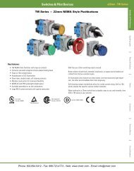
As illustrated in Figure 2, the normally-closed safety contact (i.e., safety contacts that are<br />
closed when the actuator is engaged and the solenoid is in its locking state) from each of<br />
two safety switches per interlock guard must connect to a 2-channel safety module or<br />
safety interface in order to achieve a control reliable interface to the master stop control<br />
elements of a machine. Examples of appropriate safety modules include<br />
2-channel emergency stop (E-stop) safety modules and gate monitor safety modules. Refer to<br />
Figures 3 and 4 for terminal connections.<br />
WARNING . . .<br />
It must not be possible for personnel to reach<br />
any hazard point through an opened guard (or<br />
any opening) before hazardous machine motion<br />
has completely stopped. Please reference<br />
OSHA CFR 1910.217 and AN<strong>SI</strong> B11 standards<br />
(see page 2) for information on determining<br />
safety distances and safe opening sizes for your<br />
guarding devices.<br />
CAUTION . . . Auxiliary<br />
Electrical Installation<br />
Two safety switches must be used for each<br />
interlock guard to achieve control reliability<br />
or <strong>Safety</strong> Category (per ISO 1 8 9-1,<br />
EN 95 -1) of a machine stop circuit. Use of<br />
only one safety switch per interlock guard is<br />
not recommended.<br />
In addition, normally-closed safety contacts<br />
from each of the two safety switches should be<br />
connected to the two separate inputs of a<br />
2-channel safety module or safety interface, as<br />
illustrated in Figure 2. This is required to provide<br />
monitoring for safety switch contact failure,<br />
and to provide the necessary reset routine, as<br />
required by IEC 60204-1 and NFPA 79 machine<br />
safety standards.<br />
WARNING . . . <strong>Series</strong><br />
Connection of <strong>Safety</strong><br />
Interlock <strong>Switches</strong><br />
Monitoring multiple guards with a series<br />
connection of multiple safety interlock<br />
switches is not a <strong>Safety</strong> Category<br />
Application (per ISO 1 8 9-1, EN 95 -1).<br />
A single failure may be masked or not<br />
detected at all. When such a configuration<br />
is used, procedures must be performed<br />
regularly to verify proper operation of each<br />
switch.<br />
Clearwater Tech - Phone: 800.894.0412 - Fax: 208.368.0415 - Web: www.clrwtr.com - Email: info@clrwtr.com
<strong>Safety</strong> Switch #1 <strong>Safety</strong> Switch #2<br />
32<br />
31<br />
22<br />
21<br />
Figure . Connect two redundant safety<br />
switches per interlock guard to an<br />
appropriate -channel input safety<br />
module.<br />
Solenoid<br />
Voltage<br />
Input<br />
Channel<br />
#1<br />
2-channel <strong>Safety</strong> Module<br />
E1<br />
E2<br />
13<br />
Input<br />
Channel<br />
#2<br />
(2-channel E-stop Module<br />
2-channel Gate Monitor Module, etc.)<br />
43 44<br />
14 21 22 31<br />
Figure . Switch electrical connections<br />
— models <strong>SI</strong>-<strong>QM100</strong>..G<br />
32<br />
31<br />
22<br />
21<br />
32<br />
Single gate<br />
or guard<br />
NOTE: Refer to the installation instructions<br />
provided with the safety module for<br />
information regarding the interface of<br />
the safety module to the machine stop<br />
control elements.<br />
Solenoid<br />
Voltage<br />
E1<br />
E2<br />
11<br />
43 44<br />
12 21 22 31<br />
Figure . Switch electrical connections<br />
— models <strong>SI</strong>-<strong>QM100</strong>..DSH<br />
32<br />
<strong>Machine</strong> <strong>Safety</strong> Switch – <strong>SI</strong>-<strong>QM100</strong> <strong>Series</strong>, <strong>Locking</strong> <strong>Style</strong><br />
Two functions of the safety module or safety interface are:<br />
1. to provide a means of monitoring the contacts of both safety switches for contact failure,<br />
and to prevent the machine from restarting if either switch fails; and<br />
2. to provide a reset routine after closing the guard and returning the safety contacts to their<br />
closed position. This prevents the controlled machinery from restarting by simply reinserting<br />
the safety switch actuators. This necessary reset function is required by AN<strong>SI</strong> B11 and<br />
NFPA 79 machine safety standards.<br />
Use only positively driven, normally closed safety contacts from each switch for connection<br />
to the safety module. The normally open contacts may be used for control functions that are<br />
not safety-related. A typical use is to communicate with a process controller. Refer to the<br />
installation instructions provided with the safety modules for more information regarding the<br />
interface of the safety module to the machine stop control elements.<br />
Periodic Checks<br />
<strong>Safety</strong> switches should be checked at each shift change or machine setup by a designated<br />
person (see below) for:<br />
1. Breakage of the switch body or actuator,<br />
2. Good alignment and full engagement of the actuator with the receptor,<br />
3. Confirmation that the safety switch is not being used as an end stop,<br />
4. Loosening of the switch or actuator mounting hardware, and<br />
5. Verification that it is not possible to reach any hazard point through an opened guard (or<br />
any opening) before hazardous machine motion has completely stopped.<br />
In addition, a qualified person should check for the following on a periodic schedule,<br />
determined by the user, based upon the severity of the operating environment and the<br />
frequency of switch actuations:<br />
1. Check the wiring chamber for signs of contamination.<br />
2. Check the contacts for signs of deterioration or damage.<br />
3. Inspect the electrical wiring for continuity and damage.<br />
4. Verify that wiring conforms to the instructions on pages 4 and 5 of this data sheet.<br />
A designated person is identified in writing by the employer as being appropriately trained to<br />
perform a specified checkout procedure. A qualified person possesses a recognized degree or<br />
certificate or has extensive knowledge, training, and experience to be able to solve problems<br />
relating to the safety switch installation.<br />
Clearwater Tech - Phone: 800.894.0412 - Fax: 208.368.0415 - Web: www.clrwtr.com - Email: info@clrwtr.com
<strong>Machine</strong> <strong>Safety</strong> Switch – <strong>SI</strong>-<strong>QM100</strong> <strong>Series</strong>, <strong>Locking</strong> <strong>Style</strong><br />
Repairs<br />
Do not attempt any repairs to the switch. It contains no field-replaceable components.<br />
Return the switch to the factory for warranty repair or replacement.<br />
If it ever becomes necessary to return a switch to the factory, please do the following:<br />
1. Contact the <strong>Banner</strong> applications engineering department at the number or address listed<br />
on the back cover. They will attempt to troubleshoot the system from your description of<br />
the problem. If they conclude that a component is defective, they will issue an RMA (Return<br />
Merchandise Authorization) number for your paperwork, and give you the proper shipping<br />
address.<br />
2. Pack the switch carefully. Damage which occurs in shipping is not covered by warranty.<br />
Specifications<br />
Contact Rating 4A @ 250V ac max.<br />
2.5 kV max. transient tolerance<br />
NEMA A300 P300<br />
European Rating Utilization categories: AC15 and DC13 (IEC 60947-5-1)<br />
<strong>Switches</strong> with 1 and contact pairs:<br />
Ui = 250V ac<br />
Ith = 10A<br />
Ue V<br />
40-60 Hz<br />
Ie/AC-15 A<br />
Ie/AC-13 A<br />
24 4 3<br />
110 4 0.7<br />
230 4 0.3<br />
Contact Material Silver-nickel alloy<br />
Solenoid Power<br />
Consumption<br />
5.2 W<br />
Maximum Actuator Speed 1.5 m/second (5'/second)<br />
Minimum Actuator<br />
In-line actuators: 400 mm (16")<br />
Engagement Radius<br />
Flexible actuators: 150 mm (6")<br />
Actuator Extraction Force 1000 Newtons (220 lbf) when locked<br />
Short Circuit Protection 6 amp Slow Blow, 10 amp Fast Blow. Recommended external fusing or overload protection.<br />
Mechanical Life 1 million operations<br />
Wire Connections Screw terminals with pressure plates accept the following wire sizes—<br />
16 AWG (1.5 mm2 ) max. solid; 14 AWG (2.5 mm2 ) max. stranded, 18 AWG (1 mm2 ) when using all 11 terminals<br />
Cable Entry M20 x 1.5 threaded entrance. Adapter supplied to convert M20 x 1.5 to ½" - 14 NPT threaded entrance.<br />
Construction Aluminum die-cast housing<br />
Environmental Rating IEC IP67<br />
Operating Conditions Temperature: –30° to +60° C (–22° to +140° F)<br />
Weight 0.81 kg (1.79 lb)<br />
Application Notes When rotating the actuator head, the actuator MUST BE FULLY ENGAGED.<br />
When using a model with solenoid locking, the lock mechanism will disengage upon solenoid power failure.<br />
Certifications<br />
Clearwater Tech - Phone: 800.894.0412 - Fax: 208.368.0415 - Web: www.clrwtr.com - Email: info@clrwtr.com
6.5 mm<br />
(0.26")<br />
20.0 mm<br />
(0.79")<br />
50.0 mm<br />
(1.97")<br />
45.0 mm<br />
(1.77")<br />
17.5 mm<br />
(0.69")<br />
9.8 mm<br />
(0.39")<br />
Size Model<br />
M20 x 1.5<br />
Metal<br />
Description Model*<br />
½"-14 NPT Metal<br />
Conduit Adaptor<br />
100.0 mm<br />
(3.94")<br />
M20 x 1.5<br />
1/2"-14 NPT<br />
Adapter is Supplied<br />
<strong>Machine</strong> <strong>Safety</strong> Switch – <strong>SI</strong>-<strong>QM100</strong> <strong>Series</strong>, <strong>Locking</strong> <strong>Style</strong><br />
41.3 mm<br />
(1.63") 5.2 mm<br />
(0.20") (x3)<br />
22.0 mm<br />
(0.87")<br />
30.0 mm<br />
(1.18")<br />
2.0 mm<br />
(0.08")<br />
Used with<br />
Switch Models<br />
<strong>SI</strong>-QM-CGM 0 All<br />
*NOTE: One conduit adapter is supplied with each switch.<br />
Switch Dimensions<br />
Used with<br />
Switch Models<br />
<strong>SI</strong>-QM-M 0 All<br />
Dimensions<br />
30.0 mm<br />
(1.18")<br />
Access to<br />
Manual Release<br />
(<strong>SI</strong>-<strong>QM100</strong>..MSG<br />
<strong>Series</strong> only)<br />
90.0 mm<br />
(3.54")<br />
20.0 mm<br />
(0.79")<br />
Accessories<br />
Cable Glands<br />
For Cable<br />
Diameters<br />
≥ 80 mm<br />
(3.1")<br />
ø 4.8 mm (2)<br />
2.5 mm<br />
(0.10")<br />
8.0 mm<br />
(0.31")<br />
(x2)<br />
5.0 to 12.0 mm<br />
(0.20" to 0.47") M20 x 1.5<br />
Replacement Parts<br />
Thread<br />
Conversion<br />
M20 x 1.5<br />
to<br />
½"-14 NPT<br />
3.0 mm<br />
(0.12")<br />
36.8 mm<br />
(1.45")<br />
32.0 mm<br />
60.0 (1.26") mm<br />
(2.36")<br />
116.0 mm<br />
(4.56")<br />
ø 5.2 mm<br />
(0.20") 34 mm<br />
5.2 mm (1.3")<br />
(0.20")<br />
30.0 mm<br />
(4)<br />
(1.18")<br />
Pg 13.5<br />
1/2"-14 NPSM<br />
Adapter is Supplied<br />
M20 x 1.5<br />
40.0 mm<br />
(1.56")<br />
35.5 mm<br />
(1.40")<br />
23.0 mm<br />
(0.91")<br />
12.0 mm<br />
(0.47")<br />
60.0 mm<br />
(2.36")<br />
2.0 mm<br />
(0.08")<br />
Dimensions<br />
Actuator Dimensions<br />
20.0 mm<br />
(0.79")<br />
ø 4.8 mm<br />
(2 Holes)<br />
Dimensions<br />
33.0 mm<br />
(1.30")<br />
80.0 mm<br />
(3.13")<br />
37.5 mm<br />
(1.48")<br />
1/2"-14 NPT<br />
Internal Thread<br />
80.0 mm<br />
(3.13")<br />
74.5 mm<br />
(2.93")<br />
24.0 mm<br />
(0.94")<br />
24.0 mm<br />
(0.94")<br />
15 mm<br />
(0.59")<br />
7.5 mm<br />
(0.30")<br />
Clearwater Tech - Phone: 800.894.0412 - Fax: 208.368.0415 - Web: www.clrwtr.com - Email: info@clrwtr.com<br />
O-ring<br />
36.8 mm<br />
(1.45")
<strong>Machine</strong> <strong>Safety</strong> Switch – <strong>SI</strong>-<strong>QM100</strong> <strong>Series</strong>, <strong>Locking</strong> <strong>Style</strong><br />
WARNING . . . Spare Actuators<br />
Spare actuators must NEVER be used to bypass or otherwise defeat the protective function of a safety switch. To do so may create an unsafe<br />
situation which could lead to serious injury or death.<br />
P/N 49374 rev. E<br />
Description Model<br />
Accessory Actuators<br />
Used with<br />
Switch Models<br />
In-line Flexible Metal <strong>SI</strong>-QM-SMFA All<br />
Rigid in-line metal actuator<br />
used for doors or covers.<br />
Slide-bolt design for use<br />
in heavy-duty applications<br />
where alignment is difficult<br />
to maintain.<br />
<strong>SI</strong>-QM-SB All<br />
Dimensions<br />
40 mm<br />
(1.6")<br />
50 mm<br />
(2.0")<br />
WARRANTY: <strong>Banner</strong> Engineering Corp. warrants its products to be free from defects for one year. <strong>Banner</strong> Engineering<br />
Corp. will repair or replace, free of charge, any product of its manufacture found to be defective at the time it is returned<br />
to the factory during the warranty period. This warranty does not cover damage or liability for the improper application of<br />
<strong>Banner</strong> products. This warranty is in lieu of any other warranty either expressed or implied.<br />
9.6 mm<br />
(0.40")<br />
20.0 mm<br />
(0.80")<br />
40.0 mm<br />
(1.60")<br />
4x Ø5.5 mm (0.20")<br />
3.0 mm<br />
(0.13")<br />
20.0 mm<br />
(0.80")<br />
81 mm<br />
(3.2")<br />
41 mm<br />
(1.6")<br />
42.0 mm<br />
(1.70")<br />
100.0 mm<br />
(3.9")<br />
140.0 mm<br />
(5.50")<br />
29 mm<br />
(1.1")<br />
ø 5.5 mm<br />
(0.22")<br />
38.0 mm<br />
(1.50")<br />
C L<br />
59.0 mm<br />
(2.30")<br />
31.0 mm<br />
(1.20")<br />
Ø8 mm hole<br />
for locking bolt<br />
in the open<br />
position<br />
Clearwater Tech - Phone: 800.894.0412 - Fax: 208.368.0415 - Web: www.clrwtr.com - Email: info@clrwtr.com<br />
47.0 mm<br />
(1.90")