NM Single Six - Frankonia
NM Single Six - Frankonia
NM Single Six - Frankonia

You also want an ePaper? Increase the reach of your titles
YUMPU automatically turns print PDFs into web optimized ePapers that Google loves.
2. (Refer to Figure 8, p. 24.) Align hammer in frame and insert hammer pivot<br />
with the grooved end of the pivot on the gate side of the frame. (The long<br />
screw, XR01901, when also inserted on the gate side, will intersect the groove<br />
and lock the pivot in place. See step number 11, p. 26.)<br />
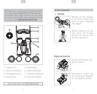
3. Replace cylinder latch and gate detent<br />
spring as shown in Figure 10. Note that<br />
the lug on the cylinder latch fits<br />
between the arms of the gate detent<br />
spring and that the end of one of the<br />
arms of the spring is formed at a 90<br />
degree angle. The projection thus<br />
formed, is designed to fit through the<br />
square hole in the bottom of the frame<br />
and to ride on the cam surface of the<br />
gate pivot. Note also that this projection<br />
holds the loading gate back and in<br />
place.<br />
Figure 10<br />
4. (Refer to Figure 8, p. 24.) Depress the upper arm of the gate detent spring<br />
with tip of screwdriver blade and install trigger pivot. Pivot should be<br />
inserted from the gate side of the frame. The non-grooved end of the pivot<br />
should be inserted first. (It may be necessary to manipulate the trigger, the<br />
gate detent spring, and the cylinder latch to align them to receive the trigger<br />
pivot.)<br />
5. Insert the base pin, taking care to be certain the ‘dished out’ section of the<br />
base pin collar is adjacent to the bottom of the barrel. The base pin must be<br />
fully inserted and locked in position by the base pin latch. If the base pin is<br />
not fully inserted and locked, the transfer bar may catch under the firing pin<br />
when the hammer is being cocked.<br />
6. (Refer to Figure 11, p. 26.) Unhook the ends of the trigger spring (XR03700)<br />
from the grooved retaining pin on both sides of the grip frame.<br />
7. Insert cylinder latch spring and plunger in hole in grip frame. (The spring<br />
goes in first so that the plunger is on top.)<br />
8. Insert pawl spring and plunger (plunger goes in the hole first) in the hole in<br />
the left side of the cylinder frame just above the left rear grip screw hole.<br />
9. Install mainspring assembly in the grip frame. Be certain the strut is<br />
positioned properly. See the Parts Drawing for correct strut positioning.<br />
10. (Refer to Figure 11, p. 26.) Draw hammer to the rear slightly and place the<br />
grip frame loosely on the cylinder frame. Before pushing the grip frame<br />
forward to mate with the cylinder frame, be certain that:<br />
(a) the cylinder latch plunger (XR07700) is positioned so that is will contact<br />
the bottom of the cylinder latch (rather than either side of the latch),<br />
(b) the pawl spring is aligned to contact the left ‘ear’ of the grip frame (and<br />
not be bent as the ear contacts it).<br />
25