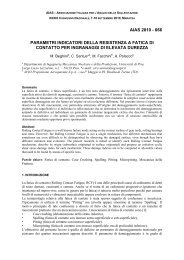
Proposal for Tip Relief Modification to reduce Noise in Spur Gears ...
Proposal for Tip Relief Modification to reduce Noise in Spur Gears ...
Proposal for Tip Relief Modification to reduce Noise in Spur Gears ...

Create successful ePaper yourself
Turn your PDF publications into a flip-book with our unique Google optimized e-Paper software.
<strong>Proposal</strong> <strong>for</strong> <strong>Tip</strong> <strong>Relief</strong> <strong>Modification</strong> <strong>to</strong> <strong>reduce</strong> <strong>Noise</strong> <strong>in</strong><br />
<strong>Spur</strong> <strong>Gears</strong> and sensitivity <strong>to</strong> mesh<strong>in</strong>g conditions<br />
Prof. M. Begh<strong>in</strong>i, Dott. F. Presicce, Dott. C. Santus ∗ ,<br />
D.I.M.N.P. - Dipartimen<strong>to</strong> di Ingegneria Meccanica Nucleare e della<br />
Produzione - Facoltà di Ingegneria, Università di Pisa - via Diotisalvi n.2<br />
Pisa, 56100 - Italy<br />
Abstract<br />
In the paper a new <strong>Tip</strong> <strong>Relief</strong> Profile <strong>Modification</strong> <strong>for</strong> spur <strong>Gears</strong> is presented. The <strong>to</strong>pography<br />
here proposed is a classical l<strong>in</strong>ear profile modification with a parabolic fillet (L<strong>in</strong>ear-Parabolic<br />
modification).<br />
The parabolic fillet extension is treated as a parameter and its effect <strong>in</strong>vestigated.<br />
The proposed <strong>to</strong>pography is able <strong>to</strong> take advantages from both L<strong>in</strong>ear, and Parabolic tip relief.<br />
The evolution from L<strong>in</strong>ear <strong>to</strong> Parabolic is discussed <strong>in</strong> terms of Peak <strong>to</strong> Peak Transmission<br />
Error. Anomalous contact conditions due <strong>to</strong> particular tip relief modification are reported, and<br />
maps are obta<strong>in</strong>ed <strong>in</strong> order <strong>to</strong> f<strong>in</strong>d optimum tip relief by tak<strong>in</strong>g <strong>in</strong><strong>to</strong> account contact conditions<br />
boundaries <strong>to</strong>o.<br />
Keywords: Transmission Error. <strong>Tip</strong> <strong>Relief</strong> Profile <strong>Modification</strong>. <strong>Spur</strong> <strong>Gears</strong>.<br />
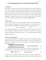
1. Introduction<br />
In a gear set, Transmission Error (TE) is def<strong>in</strong>ed as the difference between the effective and the<br />
ideal position of the output shaft with reference <strong>to</strong> the <strong>in</strong>put shaft. The ideal position represents<br />
a condition of perfect mesh<strong>in</strong>g, without geometrical errors or dis<strong>to</strong>rtions. TE can be expressed<br />
either by an angular displacement or, more conveniently, as a l<strong>in</strong>ear displacement measured<br />
along the l<strong>in</strong>e of action tangent <strong>to</strong> the base circle. TE is considered <strong>to</strong> be the primary cause of<br />
wh<strong>in</strong><strong>in</strong>g noise [1]. Indeed, wh<strong>in</strong><strong>in</strong>g noise is produced by the change of <strong>to</strong>oth load:<br />
• amplitude,<br />
• position along the profile,<br />
• direction.<br />
These chang<strong>in</strong>g are consequences of <strong>to</strong>oth deflection, local contact de<strong>for</strong>mation and body<br />
de<strong>for</strong>mation, which are the orig<strong>in</strong> of TE.<br />
Several authors [2-6] studied the correlation between TE and <strong>Tip</strong> <strong>Relief</strong> Profile <strong>Modification</strong>,<br />
s<strong>in</strong>ce it is a strong <strong>to</strong>ol <strong>to</strong> modify TE by tak<strong>in</strong>g other parameters of the gear fixed. Niemann<br />
proposed long and short modifications [4]. This different denom<strong>in</strong>ation is based on the start<br />
po<strong>in</strong>t of tip relief along the profile. Accord<strong>in</strong>g <strong>to</strong> experimental results, gears with long<br />
modification show <strong>reduce</strong>d TE excursion, <strong>in</strong>dicated as Peak <strong>to</strong> Peak Transmission Error<br />
(PPTE), and there<strong>for</strong>e little noise level at the design <strong>to</strong>rque. At lower <strong>to</strong>rque this optimum<br />
condition was not verified and an <strong>in</strong>termediate or short modification is suggested.<br />
∗ Correspond<strong>in</strong>g Author: C. Santus; e-mail: ciro.santus@<strong>in</strong>g.unipi.it<br />
Ph.: +39 050 836607, Fax.: +39 050 836665
In <strong>to</strong>oth modification design, <strong>Tip</strong> <strong>Relief</strong> is def<strong>in</strong>ed as the thickness v of the material<br />
removed along the <strong>to</strong>oth flank with reference <strong>to</strong> the nom<strong>in</strong>al <strong>in</strong>volute profile. Profile modification<br />
is usually def<strong>in</strong>ed versus the Roll Angle coord<strong>in</strong>ate (θ), Fig.1(a,b), and measured <strong>in</strong> the direction<br />
of the <strong>in</strong>ner normal, Fig.1(c).<br />
Fig. 1: (a,b) Def<strong>in</strong>ition of the profile modification function v = v(θ): Roll Angle (θ), Thickness of<br />
material removal v(θ), Start relief po<strong>in</strong>t Ps, and <strong>to</strong>tal thickness at the end of the flank v e . (c)<br />
Def<strong>in</strong>itions of: Start Active Profile (SAP), End Active Profile EAP.<br />
The k<strong>in</strong>d of function v = v(θ) is usually <strong>in</strong>dicated as Profile <strong>Modification</strong> Topography. Mesh<strong>in</strong>g<br />
sensitivity <strong>to</strong> <strong>to</strong>pography is the <strong>to</strong>pic of the paper.<br />
A different shape <strong>for</strong> the <strong>Tip</strong> <strong>Relief</strong> Profile <strong>Modification</strong> is proposed with the aim of<br />
reduc<strong>in</strong>g noise s<strong>in</strong>ce TE can be significantly smoothed if an optimized profile modification is<br />
produced [1,5,3]. Litv<strong>in</strong> [7] agree with this approach even though Tooth Contact Analysis TCA is<br />
considered only, <strong>in</strong>stead of Loaded Tooth Contact Analysis LTCA. The paper shows how the<br />
new profile tip relief modification here proposed can <strong>in</strong>fluence TE mesh<strong>in</strong>g response, accord<strong>in</strong>g<br />
<strong>to</strong> LTCA hypothesis.<br />
L<strong>in</strong>ear and Parabolic <strong>to</strong>pographies are the only shapes deeply studied [8-11].<br />
Consider<strong>in</strong>g the recent gr<strong>in</strong>d<strong>in</strong>g developments [12], it is possible <strong>to</strong> consider more complex<br />
shapes, <strong>in</strong> particular <strong>for</strong> spur gears <strong>in</strong> which profile modification is strategic.<br />
L<strong>in</strong>ear tip relief modification is of <strong>in</strong>terest s<strong>in</strong>ce it can produce little Transmission Error <strong>in</strong> spur<br />
gears if properly designed [4,11] at a given load.<br />
Parabolic profile modification satisfies tangent cont<strong>in</strong>uity condition (even though sharp curvature<br />
change is produced, C 1 cont<strong>in</strong>uity) at the profile modification start po<strong>in</strong>t, while l<strong>in</strong>ear modification<br />
does not provide further cont<strong>in</strong>uity than only C 0 and then gives rise <strong>to</strong> a sharp edge. Indeed,<br />
accord<strong>in</strong>g <strong>to</strong> solid elastic contact mechanics, sharp edge generates s<strong>in</strong>gular pressure when<br />
angular po<strong>in</strong>t falls <strong>in</strong>side the contact region [13], there<strong>for</strong>e this modification <strong>to</strong>pography is<br />
considered <strong>to</strong> be more dangerous <strong>for</strong> contact pressure which is the primary reason of micropitt<strong>in</strong>g<br />
activation [14].<br />
The new <strong>to</strong>pography here proposed is able <strong>to</strong> exploit both (l<strong>in</strong>ear and parabolic)<br />
<strong>to</strong>pographies properties, s<strong>in</strong>ce it is a l<strong>in</strong>ear relief with parabolic a fillet, Fig.2.<br />
The <strong>to</strong>pography here showed was never found by the authors <strong>in</strong> the technical literature.<br />
Transmission Error produced by the modification pattern of Fig.2 is showed <strong>in</strong> Fig.3 along with<br />
Fast Fourier Trans<strong>for</strong>m of TE. In Fig.3(b) mean value of the TE signal is elim<strong>in</strong>ated, first<br />
frequency component is predom<strong>in</strong>ant and it is remarkable that with higher load PPTE, and first<br />
frequency amplitude, can smaller than with lower load.
Anyway, as discussed <strong>in</strong> [8], simply PPTE can be effectively considered as ma<strong>in</strong> parameter of<br />
TE roughness.<br />
The <strong>to</strong>ol here exploited <strong>to</strong> f<strong>in</strong>d optimum <strong>Tip</strong> <strong>Relief</strong> configuration is plott<strong>in</strong>g a map show<strong>in</strong>g<br />
PPTE as function of start relief Roll Angles θP , θG <strong>for</strong> fixed profile modification magnitudes at<br />
the <strong>to</strong>p v e P, v e G.<br />
Fig. 2: (a) <strong>Tip</strong> relief profile modification def<strong>in</strong>ition. (b) Example of P<strong>in</strong>ion-Gear tip relief<br />
modifications and K-chart comb<strong>in</strong>ation.<br />
Fig. 3: (a) TE at low <strong>to</strong>rque and at nom<strong>in</strong>al <strong>to</strong>rque applied. (b) Fast Fourier Trans<strong>for</strong>m (FFT) of<br />
the TE signal, both cases.<br />
2. Methodology<br />
The methodology proposed by the authors is here applied [8].<br />
Mesh<strong>in</strong>g gears simulations have been carried out by means of an hybrid method, comb<strong>in</strong><strong>in</strong>g the<br />
F<strong>in</strong>ite Element technique with a semi-analytical solution [15,16].<br />
The ma<strong>in</strong> assumptions <strong>for</strong> the analysis are the follow<strong>in</strong>g:
Pla<strong>in</strong> stra<strong>in</strong> conditions Suggested by the spur gear geometry (high ratio b/h). 2D plane stra<strong>in</strong><br />
analysis is adequate <strong>for</strong> this k<strong>in</strong>d of <strong>to</strong>oth. Moreover the bi-dimensional version of the software<br />
requires little time both <strong>for</strong> model generation and simulations, with very high precision of results.<br />
Static analysis Static TE was determ<strong>in</strong>ed neglect<strong>in</strong>g rotational speed and <strong>in</strong>ertia <strong>for</strong>ces. This is<br />
the ma<strong>in</strong> assumption, obviously undertak<strong>in</strong>g dynamic analysis its <strong>to</strong>o time consum<strong>in</strong>g.<br />
Friction neglected S<strong>in</strong>ce it is assumed that it has little effect on TE output.<br />
Space error and pitch error not considered no statistical consideration was <strong>in</strong>cluded <strong>in</strong> the<br />
analysis.<br />
The quantities v e P (v e G) and θP (θG) are def<strong>in</strong>ed <strong>in</strong> Fig.1(a). The ranges <strong>for</strong> both these two<br />
variables are the Start Active Profile roll angle (SAP) and the End Active Profile roll angle (EAP)<br />
<strong>for</strong> each gear, Fig.1(b).<br />
2.1. Research boundaries<br />
Corner Contact boundary Corner contact is produced when the contact region <strong>in</strong>cludes zones<br />
of the fillet of the <strong>to</strong>oth tip [17]. As a consequence of the teeth deflection the effective contact<br />
ratio is greater than that found accord<strong>in</strong>g <strong>to</strong> rigid geometry hypothesis the contact pressure rises<br />
locally at the tip fillet, as <strong>in</strong> Fig.4.<br />
Fig. 4: (a) No contact corner detected. (b) Contact corner detected.<br />
This def<strong>in</strong>ition of Corner Contact can be exploited if a FEM analysis is per<strong>for</strong>med.<br />
When the corner contact is detected, the calculated pressure peak was not considered reliable<br />
s<strong>in</strong>ce the maximum is strongly affected by the radius of the fillet, which is a very unpredictable<br />
quantity.<br />
High Curvature boundary There is also the possibility <strong>to</strong> get anomalous contact condition if the<br />
tip relief is <strong>to</strong>o high along the <strong>to</strong>oth profile <strong>in</strong> this condition High Curvature occurs and then<br />
contact pressure is expected <strong>to</strong> be much higher then Hertz model accord<strong>in</strong>g <strong>to</strong> the nom<strong>in</strong>al<br />
<strong>in</strong>volute curvature.<br />
In Fig.5 three contact pressure his<strong>to</strong>ry are showed <strong>in</strong> which only L<strong>in</strong>ear-Parabolic profile<br />
modification parameters are modified.<br />
For each case two load conditions (Nom<strong>in</strong>al load and Low load) are showed <strong>in</strong> comparison. It is<br />
worth not<strong>in</strong>g that corner contact is related <strong>to</strong> Torque vs. <strong>Tip</strong> <strong>Relief</strong>, so configuration can show
corner contact if the load is high enough. This is obviously detectable only if Loaded Tooth<br />
Contact Analysis (LTCA) is considered<br />
Fig. 5: (a) Regular contact pressure his<strong>to</strong>ry configuration. (b) Corner Contact configuration. (c)<br />
High Curvature configuration.<br />
2.2. PPTE maps<br />
The paper ma<strong>in</strong> result is <strong>to</strong> obta<strong>in</strong> PPTE maps <strong>in</strong> order <strong>to</strong> f<strong>in</strong>d the m<strong>in</strong>imum <strong>in</strong>side an<br />
acceptance doma<strong>in</strong> def<strong>in</strong>ed accord<strong>in</strong>g <strong>to</strong> Contact Pressure. Maps hereafter presented plot<br />
PPTE as function of <strong>Tip</strong> <strong>Relief</strong> Start Roll Angle (θP, θG), which are PPTE strong dependent<br />
parameters, <strong>for</strong> given quantity of material removed at the <strong>to</strong>p (v e P, v e G). Initial values v e P, v e G<br />
have <strong>to</strong> be related <strong>to</strong> the nom<strong>in</strong>al <strong>to</strong>rque of the gear set [8-11] even though they are strong<br />
dependent parameters as well, <strong>in</strong> terms of PPTE.<br />
To def<strong>in</strong>e completely the L<strong>in</strong>ear-Parabolic modification (θP, θG) and (v e P, v e G) are not enough,<br />
transition parabolic <strong>to</strong> l<strong>in</strong>ear po<strong>in</strong>t Roll Angles need <strong>to</strong> be def<strong>in</strong>ed (θpP, θpG), Fig.2(a).<br />
It is clear that:<br />
θP < θpP < EAPP<br />
θG < θpG < EAPG (1)
To let transition from L<strong>in</strong>ear <strong>to</strong> Parabolic be described <strong>in</strong> natural fashion, configurations at fixed<br />
ratios<br />
λP = (θpP − θP)/(EAPP − θP)<br />
λG = (θpG − θG)/(EAPG − θG) (2)<br />
are considered <strong>in</strong> any s<strong>in</strong>gular maps.<br />
Limit configurations are λP(G) = 0 L<strong>in</strong>ear modification and λP(G) = 1 Parabolic modification. Maps<br />
with λ rang<strong>in</strong>g from 0 up <strong>to</strong> 1 are reported hereafter.<br />
2.3. Computational per<strong>for</strong>mances<br />
To per<strong>for</strong>m parameters sensitivity analysis, a common PC plat<strong>for</strong>m was used with the follow<strong>in</strong>g<br />
characteristics<br />
• CPU 2.6 GHz<br />
• RAM 1 GB<br />
Plane stra<strong>in</strong> analysis was per<strong>for</strong>med by ExtPair2D TM , [18, 19].<br />
Analysis were au<strong>to</strong>matically per<strong>for</strong>med <strong>in</strong> about 4.5 CPU hours, simulat<strong>in</strong>g 50 time steps <strong>for</strong><br />
each mesh<strong>in</strong>g, <strong>for</strong> 225 different tip relief (θP, θG) configurations.<br />
3. Results<br />
The above mentioned methodology was applied <strong>to</strong> a Low Contact Ratio (LCR) gear set.<br />
Ma<strong>in</strong> parameters of the set are reported <strong>in</strong> Tab.1.<br />
Table 1: LCR gear set design parameters.<br />
Modulus 1.75 mm Pressure angle 22.5 deg<br />
P<strong>in</strong>ion N. teeth 80 Gear N. teeth 1.75 mm<br />
P<strong>in</strong>ion external diameter 143.2 mm Gear external diameter 80<br />
P<strong>in</strong>ion root diameter 135.3 mm Gear root diameter 143.2 mm<br />
P<strong>in</strong>ion face width 11.0 mm Gear face width 135.3 mm<br />
P<strong>in</strong>ion v e P 23.3 µm Gear v e G 11.0 mm<br />
For the equal number of the set several symmetry properties are expected.<br />
Configuration analyzed are reported <strong>in</strong> Tab.2<br />
Table 2: Profile modification ratios, and configurations analyzed.<br />
λP(G) 0 1/4 2/4 3/4 1<br />
0 (L<strong>in</strong>)<br />
1/4 (1-1) (1-2) (1-3)<br />
2/4 (2-1) (2-2) (2-3)<br />
3/4 (3-1) (3-2) (3-3)<br />
1 (Par)<br />
Two load conditions applied <strong>to</strong> the gear set, were considered <strong>in</strong> the present paper:<br />
• 300 Nm which is considered a low load <strong>for</strong> the gear set,<br />
• 500 Nm which is the nom<strong>in</strong>al load <strong>for</strong> the gear set.
3.1. Nom<strong>in</strong>al load<br />
For nom<strong>in</strong>al <strong>to</strong>rque the effect on PPTE of the migration from L<strong>in</strong>ear <strong>to</strong> Parabolic <strong>to</strong>pography is<br />
depicted <strong>in</strong> Fig.6.<br />
Fig. 6: Nom<strong>in</strong>al load: (L<strong>in</strong>) PPTE obta<strong>in</strong>ed with L<strong>in</strong>ear modification <strong>to</strong>pography. (Par) PPTE<br />
obta<strong>in</strong>ed with Parabolic modification <strong>to</strong>pography. (i-j) Intermediate configuration mesh<strong>in</strong>g<br />
conditions.<br />
Furthermore boundaries were applied. Results are reported, only <strong>for</strong> symmetric configurations,<br />
<strong>in</strong> Fig.7.
Fig. 7: Nom<strong>in</strong>al load: (L<strong>in</strong>) L<strong>in</strong>ear modification, no boundary can be consistently applied. (Par)<br />
Parabolic modification, boundaries are wider. (i-i) Intermediate configurations.<br />
When search<strong>in</strong>g the m<strong>in</strong>imum <strong>in</strong>side boundary, it is clear that Parabolic modification is the one<br />
that offers wider acceptance doma<strong>in</strong>. There<strong>for</strong>e larger area <strong>in</strong> which PPTE produces an<br />
absolute m<strong>in</strong>imum can be considered.<br />
M<strong>in</strong>imum values <strong>for</strong> configurations showed <strong>in</strong> Fig.7 are reported <strong>in</strong> Tab.3, not consider<strong>in</strong>g<br />
boundaries.<br />
Table 3: M<strong>in</strong>imum PPTE values at the nom<strong>in</strong>al load.<br />
(L<strong>in</strong>) 1.14 µm<br />
(1-1) 0.63 µm (2-2) 0.76 µm (3-3) 0.57 µm<br />
(Par) 1.39 µm<br />
Among m<strong>in</strong>imum values reported <strong>in</strong> Tab.3 only the one referred <strong>to</strong> Parabolic modification is the<br />
acceptable. Though others are lower, they fall outside the boundary. Tak<strong>in</strong>g <strong>in</strong><strong>to</strong> account<br />
boundary, parabolic modification leads <strong>to</strong> the best result.<br />
In Fig.8 Transmission Error trace is reported both <strong>for</strong> Parabolic optimum (cont<strong>in</strong>uous l<strong>in</strong>e) and<br />
<strong>for</strong> Mid (2-2) m<strong>in</strong>imum PPTE configuration.
Fig. 8: (a) Parabolic optimum TE trace. (b) Mid configuration L<strong>in</strong>ear with Parabolic fillet optimum<br />
TE trace.<br />
PPTE is lower <strong>for</strong> Mid configuration, but Edge Contact is evident, <strong>in</strong>deed this configuration falls<br />
outside acceptance boundary as showed <strong>in</strong> Fig.7(2-2).<br />
3.2. Low load<br />
For low <strong>to</strong>rque the migration from L<strong>in</strong>ear <strong>to</strong> Parabolic <strong>to</strong>pography is depicted <strong>in</strong> Fig.9.<br />
For this load level no boundary related <strong>to</strong> contact pressure was applied, s<strong>in</strong>ce load is not<br />
expected <strong>to</strong> be dangerous at this level. Even <strong>to</strong>ugh there necessary are conditions of<br />
anomalous contact (Edge Contact or High Curvature) also at lower load, it is possible <strong>to</strong> assume<br />
that they are conf<strong>in</strong>ed <strong>to</strong> not useful configurations. M<strong>in</strong>imum values found at the different<br />
configurations are reported <strong>in</strong> Tab.4.<br />
Table 4: M<strong>in</strong>imum PPTE values at the low load.<br />
(L<strong>in</strong>) 0.87 µm<br />
(1-1) 0.39 µm (2-2) 0.53 µm (3-3) 0.52 µm<br />
(Par) 0.95 µm<br />
It is worth not<strong>in</strong>g that nor L<strong>in</strong>ear neither Parabolic <strong>to</strong>pography generates m<strong>in</strong>imum PPTE at both<br />
loads.<br />
M<strong>in</strong>imum PPTE output is generated by a L<strong>in</strong>ear <strong>to</strong> Parabolic configuration depend<strong>in</strong>g on the<br />
load. To propose this as “golden” rule is not the aim of the paper, s<strong>in</strong>ce this can be strongly<br />
deviated by mesh<strong>in</strong>g parameter. The contribute of the paper is <strong>to</strong> show that the parabolic fillet<br />
can be an effective parameter <strong>to</strong> obta<strong>in</strong> an optimum solution.<br />
3.3. Sensitivity <strong>to</strong> centre distance<br />
Sensitivity <strong>to</strong> mesh<strong>in</strong>g conditions are here proposed.<br />
In order <strong>to</strong> avoid a huge amount of graphical output, L<strong>in</strong>ear modification at Nom<strong>in</strong>al load<br />
sensitivity <strong>to</strong> centre distance offset is considered. Results are showed <strong>in</strong> Fig.10.<br />
The entities of offset are around ±1/10 <strong>in</strong> comparison with modulus, it is clear <strong>to</strong> understand that<br />
perturbation <strong>in</strong>duced by mesh<strong>in</strong>g condition have <strong>in</strong>fluenced little PPTE map.
Fig. 9: Low load: (L<strong>in</strong>) PPTE obta<strong>in</strong>ed with L<strong>in</strong>ear modification <strong>to</strong>pography. (Par) PPTE obta<strong>in</strong>ed<br />
with Parabolic modification <strong>to</strong>pography. (i-j) Intermediate configuration mesh<strong>in</strong>g conditions.<br />
4. Conclusions<br />
In the present paper a new <strong>Tip</strong> <strong>Relief</strong> Profile <strong>Modification</strong> is proposed along with Loaded Tooth<br />
Contact Analysis methodology analysis. Static Peak <strong>to</strong> Peak Transmission Error (PPTE) is<br />
considered as ma<strong>in</strong> mesh<strong>in</strong>g output s<strong>in</strong>ce it can be related <strong>to</strong> noise level. Extensive parametric<br />
numerical analysis results are presented. PPTE maps are reported as function of P<strong>in</strong>ion and<br />
Gear Start <strong>Tip</strong> <strong>Relief</strong> Roll Angles. Migration from L<strong>in</strong>ear <strong>to</strong> Parabolic modification is effectively<br />
described.
Fig. 10: (a) L<strong>in</strong>ear modification. (b) L<strong>in</strong>ear modification with offset -0.2 mm. (c) L<strong>in</strong>ear<br />
modification with offset +0.2 mm.<br />
Contact Pressure anomalies are presented and applied as limit of acceptance on PPTE maps.<br />
<strong>Modification</strong>s near <strong>to</strong> parabolic can show wider acceptance doma<strong>in</strong>, s<strong>in</strong>ce Edge Contact and<br />
strong curvature issues are less dangerous.<br />
Optimum configuration is here found <strong>for</strong> a gear set at a given load. The new <strong>to</strong>pography<br />
<strong>in</strong>troduces a degree of freedom that can be useful <strong>in</strong> design optimum profile modification <strong>for</strong> any<br />
gear set.<br />
References<br />
[1] Smith J.D. <strong>Gears</strong> and theirs vibration, A Basic Approach <strong>to</strong> Understand<strong>in</strong>g Gear <strong>Noise</strong>.<br />
The Macmillan Press LTD., 1983.
[2] Harris S. Dynamic loads on the teeth of spur gears. ProcIMechE, (1958) 3 pp. 172-187.<br />
[3] Munro R. G., Yildirim N., Hall D.M. Optimum profile relief and transmission error <strong>in</strong> spur<br />
gears. Proceed<strong>in</strong>gs of the First International Conference on Gearbox <strong>Noise</strong> and<br />
vibration, 1990 pp. 35-41.<br />
[4] Niemann G., W<strong>in</strong>ter H. Mach<strong>in</strong>enelemente Band II, Getriebe allgema<strong>in</strong>, ahnradgetriebe,<br />
volume 2. Grundlagen, Stirnradgetriebe, Spr<strong>in</strong>ger-Verlag, Berl<strong>in</strong>, 1983.<br />
[5] Niemann G., Baethge J. Transmission error <strong>to</strong>oth stiffness, and noise of parallel axis<br />
gears. VDIZ, 112(4), 1970.<br />
[6] Walker H. Gear <strong>to</strong>oth deflections and profile modifications. Eng<strong>in</strong>eer, (1938) 166 pp.<br />
409-412, pp. 434-436.<br />
[7] Litv<strong>in</strong> F. L., A. Fuentes. Gear Geometry and Applied Theory. Cambridge University<br />
Press, 2004.<br />
[8] Begh<strong>in</strong>i M., Presicce F., C. Santus. A method <strong>to</strong> def<strong>in</strong>e profile modification of spur gear<br />
and m<strong>in</strong>imize the transmission error. Proceed<strong>in</strong>gs of AGMA Fall Technical Meet<strong>in</strong>g<br />
2004, Oc<strong>to</strong>ber 2004. Milwaukee, WI.<br />
[9] Wagaj P., Kahraman A. Impact of <strong>to</strong>oth profile modifications on the transmission error<br />
excitation of helical gear pairs. Proceed<strong>in</strong>gs of ESDA2002: 6th Biennial Conference on<br />
Eng<strong>in</strong>eer<strong>in</strong>g Systems Design and Analysis, July 2002. Istanbul, Turkey.<br />
[10] Kartik V., Houser D.R. Analytical predictions <strong>for</strong> the transmission error excitation <strong>in</strong><br />
various multiple-mesh gear-tra<strong>in</strong>s. Proceed<strong>in</strong>gs of DETC’2003 ASME Design<br />
Eng<strong>in</strong>eer<strong>in</strong>g Technical Conferences and Computers and <strong>in</strong><strong>for</strong>mation <strong>in</strong> Eng<strong>in</strong>eer<strong>in</strong>g<br />
Conferences, 2003.<br />
[11] Tavakoli M. S., Houser D.R. Optimum profile modification <strong>for</strong> the m<strong>in</strong>imization of static<br />
transmission errors of spur gears. Proceed<strong>in</strong>gs of ASME 84 - DET - 173, 1986.<br />
[12] H. Geiser. <strong>Noise</strong> optimized modifications: Renaissance of the generat<strong>in</strong>g gr<strong>in</strong>ders?<br />
Proceed<strong>in</strong>gs of AGMA Fall Technical Meet<strong>in</strong>g 2004, Oc<strong>to</strong>ber 2004. Milwaukee, WI.<br />
[13] Johnson K.L. Contact Mechanics. Cambridge University Press, 1985.<br />
[14] Begh<strong>in</strong>i M., Bragall<strong>in</strong>i G.M., Presicce F., Santus C.. Influence of the l<strong>in</strong>ear tip relief<br />
modification <strong>in</strong> spur gears and experimental evidence. Proceed<strong>in</strong>gs ICEM12, Sepetmber<br />
2004. Bari.<br />
[15] Vijayakar S.M., Houser D.R. Contact analysis of gears us<strong>in</strong>g a comb<strong>in</strong>ed f<strong>in</strong>ite element<br />
and surface <strong>in</strong>tegral method. Proceed<strong>in</strong>gs of FIGMA Technical meet<strong>in</strong>g, 1991.<br />
[16] Vijayakar S.M., Houser D.R., Busby H.R.. A summary of a new f<strong>in</strong>ite element technique<br />
with special application <strong>to</strong> gears. Proceed<strong>in</strong>gs of Int. Conf. of Gear<strong>in</strong>g, (1988)2 pp. 813-<br />
817.<br />
[17] Litv<strong>in</strong> F. L., Fuentes A., Gonzalez-Perez I., Carvenali L., Kawasaki K., Handschuh R. F.<br />
Modified <strong>in</strong>volute helical gears: computerized design, simulation of mesh<strong>in</strong>g and stress<br />
analysis. Computer Methods <strong>in</strong> Applied Mechanics and Eng<strong>in</strong>eer<strong>in</strong>g, (2003) 192 pp.<br />
3619–3655.<br />
[18] Vijayakar S.M. Calyx Users Manual. Advanced Numerical Solutions, Hilliard OH, March<br />
2003.<br />
[19] Vijayakar S.M. Helical3D User’s Manual. Advanced Numerical Solution, Hilliard OH,<br />
March 2003.