Children's therapeutic bed Lisa Instruction manual - FreiStil Tischlerei
Children's therapeutic bed Lisa Instruction manual - FreiStil Tischlerei
Children's therapeutic bed Lisa Instruction manual - FreiStil Tischlerei

Create successful ePaper yourself
Turn your PDF publications into a flip-book with our unique Google optimized e-Paper software.
<strong>FreiStil</strong> <strong>Tischlerei</strong><br />
Kroh + Kinstler GmbH & Co. KG<br />
Ruppenkampstraße 16<br />
D - 49084 Osnabrück<br />
Fon ++49 - 541 – 77974<br />
Fax ++49 - 541 – 77596<br />
E-mail info@freistil.com<br />
Homepage: www.freistil.com<br />
OM 2012 <strong>Lisa</strong> synchro – T<br />
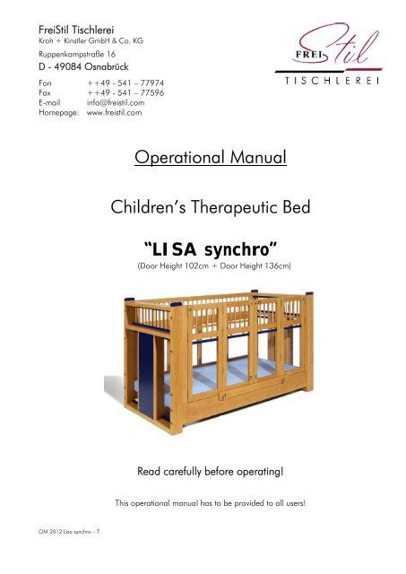
Operational Manual<br />
Children’s Therapeutic Bed<br />
“LISA synchro”<br />
(Door Height 102cm + Door Height 136cm)<br />
Read carefully before operating!<br />
This operational <strong>manual</strong> has to be provided to all users!
TABLE OF CONTENTS<br />
1. Installation Manual (for authorized sales agents/distributors only) page<br />
OM 2012 <strong>Lisa</strong> synchro – 01<br />
1.1 Assembly of <strong>bed</strong> frame 02<br />
1.2 Steering, Double Motor + Cable Splice 02<br />
1.3 Rear transverse joint of L-angles + <strong>bed</strong> base 03<br />
1.4 Installation of roller blind case 03<br />
1.5 Installation of rear frame 04<br />
1.6 Installation of doors 04<br />
1.7 Door locks (squared latch, swing stopper, transverse ledge) 04<br />
1.8 Fixing of inner doors 05<br />
1.9 EXTRA: Adjustment of <strong>bed</strong> base by electric motor 05<br />
1.10 EXTRAS: Upper lock mechanism of doors 05<br />
1.11 EXTRAS: Transport wheels 05<br />
2. Operational Manual<br />
2.1 Purpose of use 06<br />
2.2 Important notice for operational safety 06<br />
2.3 Warning notice 07<br />
2.4 Start-up the electric System – initialisation 07<br />
2.5 Lifting motors 07<br />
2.6 Bed base 08<br />
2.7 Manual control switch (Keyboard, functions, first fault protection) 08/08.1<br />
2.8 Revolving doors 09<br />
2.9 Transport wheels 09<br />
2.10 Fixing of inner doors 09<br />
2.11 Cleaning, maintenance and re-usage (list of spare parts) 10<br />
2.12 Accessories 10<br />
2.13 Symbols 10<br />
3. Technical Data<br />
3.1 Bed frame 11<br />
3.2 Lifting unit 11<br />
3.3 Bed base 11<br />
3.4 Motors 11<br />
4. Annex (for authorized sales agents only)<br />
4.1 Maintenance instructions / CHECK LIST CH1<br />
4.1.1 General instructions CH1<br />
4.1.2 Check list / Electric motor CH2<br />
4.1.3 Check list / Bed base CH3<br />
4.1.4 Check list / Bed frame CH4
1. INSTALLATION MANUAL<br />
The installation has to be carried out by trained specialized staff only. We recommend installation by<br />
two people following these steps:<br />
1.1 On the inner side of the <strong>bed</strong> there are stickers with numbered arrows from 1 to 4 (pict. 1).<br />
Assign the side panels, head- and foot-end according to these numbers.<br />
Now screw side panels, head- and foot-end together according to the numbers by using the<br />
Allen screws (M8 x 130mm) attached (pict. 2)<br />
Do not yet tighten the screws, leave some space to insert the rear panel!!!<br />
picture 1 picture 2<br />
1.2 Fix the supporting plate for steering + safety panel to<br />
head-and food-end at the positions marked (pict. 3).<br />
Width of <strong>bed</strong> 1000 mm = drilling in the MIDDLE<br />
Width of <strong>bed</strong> 800 mm /head left = drilling RED<br />
Width of <strong>bed</strong> 800 mm /head right = drilling GREEN<br />
Connect the wires of the lifting columns’ motor as well as the<br />
cable of the <strong>manual</strong> control with the steering unit (pict. 4.1)<br />
For models with electrically adjustable head- and foot-end<br />
(Extra) connect the cable of the double-motor with the<br />
steering unit (pict. 4.2). picture 3<br />
Mark of motor for the head-end = RED<br />
Finally fix the safety-cover for the plugs.<br />
Attention! Wires must not be damaged or crushed at any time during or after installation !!!<br />
OM 2012 <strong>Lisa</strong> synchro – 02<br />
picture 4.1 picture 4.2
1.3 At the rear install flat steel bars for the traverse joint of the<br />
L-angles of lifting columns, using the hexagonal screws<br />
(M8 x 10 mm) attached (pict.5)<br />
After that place the <strong>bed</strong> base onto the L-angle + the rear<br />
traverse joint (pay attention the position of the head-end) and<br />
fix it with the wood-screws (4 x 25 mm) attached (pict. 5+6).<br />
Thereby the L-angles always have to be in parallel position<br />
to the <strong>bed</strong> base. The frame of <strong>bed</strong> base has to be aligned picture 5<br />
with the L-angle (pict. 7).<br />
picture 6 picture 7<br />
1.4 The pre-installed roller blind is delivered in a plywood box.<br />
Put the plywood box in centre at the front-side inside the <strong>bed</strong><br />
meeting the support (pict. 8).<br />
For models with “doors on both sides” (EXTRA) place the<br />
second plywood box at the rear of <strong>bed</strong> meeting the support.<br />
Pull the textile safety panel out of the plywood box, guide it around the<br />
aluminium-pipe and place it into the groove at the underside of <strong>bed</strong> base.<br />
Fit the blind together with the angle wood into the groove. Then fix the<br />
angle wood by using the wood screws (3,5 x 20 mm) enclosed (pict.9).<br />
OM 2012 <strong>Lisa</strong> synchro – 03<br />
picture 8 picture 9
1.5 The sides of the rear panel are marked with colours.<br />
RED: left<br />
GREEN: right<br />
(looking from the door-side onto the <strong>bed</strong>)<br />
Place lower part of rear panel between head- and foot-end<br />
according to the colour-marks and secure them with the<br />
Allen screws (M8 x 130mm) enclosed.<br />
After that insert the enclosed wooden springs into the<br />
milled edge and place the upper part of the rear panel<br />
according to the colour-marks on top of the lower part<br />
and connect the two rear parts firmly by using the screws<br />
(M8 x 130mm) enclosed (pict. 12).<br />
Now tighten all screws (including <strong>bed</strong> frame) firmly!!! picture 12<br />
1.6 The two units of doors are marked by colours:<br />
RED: left<br />
GREEN: right<br />
(looking from the door-side onto the <strong>bed</strong>)<br />
Fix the first unit of doors according to the colour-marks<br />
With the head- respectively the foot-end panel of the <strong>bed</strong><br />
frame by using the screws (M8 x 130mm) enclosed (pict. 13).<br />
Install second unit of doors accordingly (pict. 13).<br />
1.7 The outer doors are locked respectively opened by<br />
a squared latch (pict. 14).<br />
The middle doors are locked by a simple swing stopper.<br />
Simply move the handle along the groove to close or open<br />
the door (pict. 15).<br />
There are two swing stoppers in the lower part of the doors,<br />
but one in the upper part (pict. 16).<br />
Additionally the doors can be secured by a “transverse ledge”<br />
(pict. 16 + pict. 17).<br />
picture 13<br />
picture 14<br />
picture 15 picture 16 picture 17<br />
OM 2012 <strong>Lisa</strong> synchro – 04
1.8 Blocking of Inner Doors<br />
The inner doors are provided with magnets in order to<br />
avoid unintended shut (pict. 16).<br />
1.9 OPTIONAL: EXTRA<br />
Head- and foot-end adjustable by electric motor.<br />
Connect the wires of double-motor with the steering (pict. 17)<br />
Mark of motor for the head-end = RED<br />
Then fit the cover protecting the plugs.<br />
1.10 OPTIONAL: EXTRA<br />
Safety Catch of doors.<br />
The doors can be additionally stabilized in the upper part by<br />
an U-shaped wooden ledge (pict. 18).<br />
After placing the transverse ledge onto the doors according<br />
the moulded space in the upper frame of the two middle<br />
doors, turn the locking pin by 90° (it will be locked by<br />
suspension of the spring).<br />
To unlock, pull the locking pin and turn it by another 90° into<br />
resting position.<br />
1.11 OPTIONAL: EXTRA<br />
Transport Wheels<br />
Double break castor 100 x 30mm.<br />
To lock press down foot lever, to unlock pull it up.<br />
picture 16<br />
picture 17<br />
picture 18<br />
Every time the <strong>bed</strong> had been moved into position all castors have to be locked firmly!<br />
Manufacturer: <strong>FreiStil</strong> <strong>Tischlerei</strong> Kroh + Kinstler GmbH & Co. KG<br />
Ruppenkampstraße 16, D - 49084 Osnabrück<br />
Fon ++49 - 541-77 974, Fax ++49 - 541-77 596<br />
email: info@freistil.com; www.freistil.com<br />
OM 2012 <strong>Lisa</strong> synchro - 05
2. OPERATING DIRECTIONS<br />
2.1 Purpose of use<br />
The children’s <strong>therapeutic</strong> <strong>bed</strong> „LISA“ is designed for private use at home as well as for domestic<br />
care. Its medical objective is to provide the alleviation, treatment and surveillance of illness and<br />
injuries by the various resting positions for the child. The multifunctional options increase the benefit.<br />
For safety reasons the <strong>bed</strong> is not for use for medical treatments using electricity, since this model is<br />
not conceived as a hospital <strong>bed</strong>. It is licensed for one (1) person only and the maximum weightbearing<br />
capacity (see specification label) may not be exceeded. The <strong>bed</strong> is for indoor use only and<br />
has to be protected from high humidity. All technical functions can be controlled by a lockable IPX4<strong>manual</strong><br />
switch.<br />
All components of the <strong>bed</strong> are only permitted for use according to its intended purpose.<br />
Overload may cause damage and is not permitted.<br />
2.2 Important notes for operational safety<br />
I. Set-up and initial operation have to be carried out by authorized distributors. A functional test<br />
has to be carried out prior to handing the <strong>bed</strong> over to the customer. Attention has to be paid<br />
to: the smooth running of all functions, the installation of power supply according to the<br />
regulations, the firm installation of the lifting unit within the <strong>bed</strong> frame as well as the fixing of<br />
the <strong>bed</strong> base to the lifting unit. This also applies to further operation of the children’s<br />
<strong>therapeutic</strong> <strong>bed</strong>.<br />
Improper installation of mains connection may cause serious damage (electric shock)<br />
to people.<br />
II. The maximum weight of the patient must not exceed 100 kg. People of any age with limited<br />
perceptive faculty may operate the system under supervision only.<br />
III. The lowest position of the <strong>bed</strong> base is the safest position and should be used in any case,<br />
unless therapy and nursing require a different position.<br />
After treatment always return the lifting unit to its lowest position.<br />
IV. While moving the lifting unit make sure that no parts of the body<br />
get in or under the moving elements. DANGER OF BEEING<br />
CRUSHED!<br />
V. The <strong>therapeutic</strong> <strong>bed</strong> for children „LISA“ is designed for dry rooms<br />
and must be used and stored in such rooms only.<br />
The system may only be operated by state-of-the-art 230 Volt plugs. Cables + plugs have to<br />
be dry. Make sure that cables are not crushed or do not rub against anything. Pay attention to<br />
the proper laying and fixing of all cables at the positions advised.<br />
VI. To avoid overload and defects of the electric engine the power-on time must not exceed a<br />
maximum time of 2 minutes.<br />
The electric adjustment for head- and foot-end must only be used for lowering/lifting<br />
upper body or legs of the patient (patient must be in proper position!).<br />
Overload causes damage and is not permitted!!!<br />
Also overloading the mechanical components causes damage and therefore is not permitted<br />
(see Operational Manual TOP 2.3 + 2.4 as well as specification label).<br />
VII: Liability for any kind of damages and injuries is explicitly excluded in case of misuse, improper<br />
use, wrong operation or inexpert installation/repair. Furthermore all kinds of guarantees are<br />
also excluded in such a case.<br />
OM 2012 <strong>Lisa</strong> synchro – 06
VIII. The electric engines of the <strong>bed</strong> may not be used in locations where inflammable gases or<br />
fumes occur.<br />
IX. The <strong>therapeutic</strong> <strong>bed</strong> „LISA“ may only be operated and maintained by using original<br />
accessories and original spare parts.<br />
X. Operational malfunction must be reported immediately to the authorized distributor.<br />
Stop using the equipment and disconnect the mains, especially when electrical or<br />
mechanical parts are damaged.<br />
2.3 Warnings<br />
I. Transport of the patient is only permitted in the lowest, horizontal position of the lifting unit.<br />
II. While the patient is unattended the lifting unit has to be on its lowest position.<br />
Revolving doors have to be firmly locked.<br />
III. Do not leave things behind in the <strong>bed</strong> that could be used for climbing up or can lead to<br />
suffocation or strangulation.<br />
IV. The lifting unit must only be operated by people briefed or by the nursing staff.<br />
The patient must not operate the <strong>bed</strong> themselves.<br />
While the patient is unattended all functions have to be locked.<br />
V. The patient’s clinical condition may increase the danger of being squeezed in.<br />
VI. DANGER OF BEING SQUEEZED IN when opening or closing the revolving doors.<br />
In an open state, the middle parts of the revolving doors are secured by magnets.<br />
The complete door units must only be opened + closed while the patient is<br />
under supervision.<br />
VII. The <strong>therapeutic</strong> <strong>bed</strong> „LISA“ must only be used upon even, horizontal and<br />
solid ground.<br />
VIII. Use <strong>bed</strong> in dry rooms only.<br />
IX. Do not place the <strong>bed</strong> near open fire or other strong heat sources (i.e. electric radiator,<br />
gas heater etc.).<br />
X. Maximum safe weight-bearing capacity is 100 kg.<br />
Electric adjustment of head- and foot-end (accessories) must only be used for lifting/lowering<br />
the upper body or the legs (Make sure the patient is in appropriate position).<br />
2.4 Start-up the electric system – initialisation<br />
Bring the <strong>bed</strong> base from any treatment position down to the lowest position. Therefore press the<br />
two lowest buttons of the <strong>manual</strong> control unit simultaneously. After approx. 10 seconds the lifting<br />
motors start to move the <strong>bed</strong> base downwards. During that procedure the functions LED on the left<br />
topside of the <strong>manual</strong> control unit flashes RED. After the <strong>bed</strong> base has reached the lowest position,<br />
keep pressing the two buttons of the <strong>manual</strong> control for further approx. 5 seconds until the functions<br />
LED has switched to GREEN. Now the system is initialised and ready to operate.<br />
The initialisation has to be carried out every time before operating the system + after any power<br />
failure.<br />
OM 2012 <strong>Lisa</strong> synchro – 07
2.5 Lifting motors<br />
The lifting motors serve the purpose of lifting the <strong>bed</strong> base up and down.<br />
Maximum patient weight: 100 kg.<br />
Safe working load: 170 kg, incl. equipment.<br />
Overload will cause damage and therefore is not permitted.<br />
2.6 Bed base<br />
Standard equipment: <strong>manual</strong>ly adjustable head- and foot-end.<br />
EXTRA: Accessories<br />
Head- and foot-end adjustable by electric motor.<br />
It is not recommended to move the head- and foot-end to<br />
the highest position at the same time. The patient may be<br />
cramped in and feel uncomfortable.<br />
In case of power failure or defective motor head- and foot-<br />
end as well as the <strong>bed</strong> base can be lowered by battery<br />
(pict. 19).<br />
There is enough energy for only one emergency lowering.<br />
Exchange of the battery is essential after only one picture 19<br />
operation respectively with every maintenance.<br />
2.7 Manual Control Unit<br />
While operating the electric adjustment no items and no limb is allowed in the moving area.<br />
All electric functions can be operated by the <strong>manual</strong> control unit. The options of adjustment<br />
of height and positions of the base are marked by the corresponding symbols. By gently<br />
pressing the respective button the system moves to the required position. Attention: operate<br />
only one function at the same time.<br />
Please pay attention that during operation the wire of the <strong>manual</strong> control unit is not<br />
crushed! To avoid malfunction do place the <strong>manual</strong> control unit onto the <strong>bed</strong> frame,<br />
when not in use. The key pad should be facing away from the <strong>bed</strong>.<br />
The control unit has a lock function: with a special key one can operate a rotary switch at<br />
the backside of the control unit. On the display of the key shows either an open<br />
lock(unblocked) or a closed lock (blocked).<br />
The key is a safety element preventing unauthorized use of the <strong>manual</strong> control unit.<br />
Therefore it always has to be kept separate from the <strong>manual</strong> control.<br />
On the following page you will find details on keys + a diagram of functions of the <strong>manual</strong><br />
control unit:<br />
OM 2012 <strong>Lisa</strong> synchro – 08
Keys and Functions<br />
Manual control unit with 6 buttons for adjustment of positions<br />
All electric functions can be operated by the <strong>manual</strong> control unit. The options of adjustment of<br />
height and positions of the base are marked by the respective symbols. By gently pressing the<br />
respective button the system moves to the required position. Attention: operate only one function<br />
at the same time.<br />
SYMBOL ‘KEY’<br />
Green LED = Functions of control unit available<br />
No LED = Functions of control unit locked<br />
SYMBOL ‘YELLOW TRIANGLE’<br />
Green LED = Ready to operate<br />
Red LED = Error message<br />
(Check: disconnect the system from power, disconnect the battery,<br />
Reconnect the battery, check the plug-in conncections, plug in the system)<br />
INITIALISATION = Button 5 + 6 (hight adjustment) - press simultaneously<br />
Red LED Flash = During initialisation<br />
Green LED = Initialisation completed<br />
The control unit has a lock function: with a special key one can operate a rotary switch at the<br />
backside of the control unit. On the display of the special key shows either an open lock(unlocked)<br />
or a closed lock (locked).<br />
Symbol ‘open lock’ = Ready to operate<br />
Symbol “closed lock’ = Functions of control unit blocked<br />
OM 2012 <strong>Lisa</strong> synchro – 08.1
2.8 Revolving Doors<br />
The outer doors are fixed and opened by a squared<br />
latch (pict. 20). The doors in the middle can be<br />
locked by an easy to handle swing stopper. Just move<br />
the hand-lever along the groove in order to open or to close<br />
the doors (pict. 21). There are 2 swing stoppers in the lower<br />
part and 1 swing stopper in the upper part of the doors.<br />
The doors can be additionally secured by a movable ledge<br />
(pict. 22), and, if requested, stabilized by an U-shaped<br />
wooden bolt (EXTRA) across the upper part of the doors picture 20<br />
(pict. 23). It will be locked by suspension of the locking pin.<br />
picture 21 picture 22 picture 23<br />
2.9 Transport Wheels<br />
EXTRA: Accessories<br />
Break castor wheels 100 x 30mm, double break function.<br />
To lock press down foot lever,<br />
to unlock pull it up.<br />
Every time the <strong>bed</strong> had been moved into position all castors have to be locked firmly!<br />
2.10 Blocking of Inner Doors<br />
The inner doors are provided with magnets in order to<br />
avoid unintended shuting (pict. 24.)<br />
OM 2012 <strong>Lisa</strong> synchro – 09<br />
Bild 24
2.11 Cleaning, Maintenance and Re-use<br />
The polished surface ensures easy cleaning and disinfection. Neither the electric equipment nor<br />
the <strong>bed</strong> frame should be cleaned by high pressure cleaning equipment. For cleaning, use a<br />
damp cloth and a little neutral soap, dry afterwards using a dry cloth.<br />
Disinfection of the <strong>bed</strong> with a commercially available disinfecting agent is possible.<br />
Re-use is possible after proper cleaning, disinfection and maintenance.<br />
Maintenance must be carried out by the authorized distributor. A check up on all functions<br />
should be done prior to re-use of the <strong>bed</strong> or at the patient’s house when the <strong>bed</strong> had been on<br />
long-term use. A 2-years period for check ups on all components is obligatory.<br />
Spare part lists available from the manufacturer!<br />
2.12 EXTRAS<br />
Nursing mattress type „Grisu“, flame-retardent<br />
Retouching pen for metal frame<br />
Set for surface treatment of the wooden parts<br />
2.13 Symbols<br />
Protection class II<br />
Use in dry rooms only<br />
Danger of being squeezed or crushed<br />
Important notice in Operating Directions<br />
Application part Type B<br />
Manufacturer: <strong>FreiStil</strong> <strong>Tischlerei</strong> Kroh + Kinstler GmbH & Co. KG<br />
Ruppenkampstraße 16, D - 49084 Osnabrück<br />
Fon ++49 - 541-77 974, Fax ++49 - 541-77 596,<br />
email: info@freistil.com, www.freistil.com<br />
OM 2012 <strong>Lisa</strong> synchro – 10
3. TECHNICAL DETAILS<br />
3.1 Bed Frame<br />
Exterior dimensions: 1.076 x 2.230 mm<br />
876 x 1.950 mm<br />
Interior dimensions: 1.000 x 2.000 mm<br />
800 x 1.700 mm<br />
Height of <strong>bed</strong>: 1.658 mm<br />
Top level of mattress 320 – 1.020 mm<br />
Height of doors: 1.020mm + 1.360 mm<br />
Weight of Bed frame + Lifting unit (Door height 136cm) approx. 245 kg<br />
Weight of:<br />
Head- and foot-end panel 90 kg<br />
Side panels 20 kg<br />
Rear part incl. bars or spectar® 35 kg<br />
Revolving doors 50 kg<br />
Total weight of <strong>bed</strong> frame: approx. 195 kg<br />
Mattress standard: RG35 12 cm, approx. 5 kg<br />
3.2 Lifting Unit: ilcoDrive BZ ICS<br />
Dimensions (length x width x height): 130 x 71 x 22 cm<br />
Weight approx. 15 kg<br />
Lifting width 700 mm<br />
Lifting capacity 2 x 3000N<br />
3.3 Steering Unit: ilcoPower TD ICS<br />
Mains voltage 240 VAC / 50-60 hz<br />
Sockets 4 motors / 1 <strong>manual</strong> control unit<br />
Protective class II<br />
3.4 Bed base: M+K Holztechnik „JUMBO II“<br />
Dimensions 96 x 195 cm<br />
Number of pieces 2<br />
Weight approx. 30 kg<br />
Maximum weight bearing capacity 100 kg<br />
3.5 Engines: ilcoFlexx 581 ICS<br />
Mains voltage / frequence 240 volt / 50-60 hz<br />
Engine voltage 24 volt<br />
Protective class II<br />
Sound output 38 dB (A)<br />
Term of operating max. 2 min / 5 cycles per min<br />
Technical Details may be subject to alterations!<br />
Manufacturer: <strong>FreiStil</strong> <strong>Tischlerei</strong> Kroh + Kinstler GmbH & Co. KG<br />
Ruppenkampstraße 16, D - 49084 Osnabrück<br />
Fon ++49-541-77 974, Fax ++49-541-77 59<br />
email: info@freistil.com, www.freistil.com<br />
OM 2012 <strong>Lisa</strong> synchro – 11
4. ANNEX<br />
4.1 Maintenance <strong>Instruction</strong>s / CHECK LIST<br />
With this maintenance instructions we will enable you to carry out the requested safety<br />
and technical check-ups as requested by REGULATIONS for USERS of MEDICAL PRODUCTS,<br />
Germany (MPBetreibV). Further regulations/laws of the legislator or professional<br />
organisations are not covered.<br />
The instructions are structured as following:<br />
4.1.1. General Notes<br />
4.1.2 CHECK LIST / Electric Motors<br />
4.1.3 CHECK LIST / Lifting Unit<br />
4.1.4. CHECK LIST / Bed base<br />
4.1.5 CHECK LIST / Bed frame<br />
4.1.1 General Notes<br />
OM 2012 <strong>Lisa</strong> synchro – CH1<br />
- Maintenance and repair works may be carried out by qualified and authorized<br />
personnel only. (The manufacturer of the electric motor requests<br />
an individual authorisation of the personnel given by himself in order to entitle<br />
them for repair works!)<br />
- Maintenance<br />
electrical equipment every 12 months<br />
Regular inspection of electric resistor and leakage current according to VDE<br />
751-1, using a gauge manufactured i.e. by Bentron, Mertens or equal.<br />
mechanical components every 12 months<br />
Maintenance inspections may be carried out at site of installation. Further<br />
repair works have to be carried out at suitable work stations.<br />
- Only original spare parts are permitted. Self-made components will make<br />
expire any liability or guarantee by the original manufacturer.<br />
List of spare parts is available from the manufacturer.<br />
- Alterations in the system, modifications and /or extensions require the prior<br />
written approval by the manufacturer.<br />
- There has to be run a complete functional test after each and every<br />
maintenance and/or repair. Pay attention to all moving parts running without<br />
collision in order to avoid any kind of hazards to patient and others as well as<br />
damages to the material and the components.<br />
- In order to enable you to document your work we enclosed provide some<br />
CHECK-LISTS to tick off.<br />
Further check-ups necessary, i.e. according to accident prevention rules<br />
released by the professional association or any accident prevention<br />
association etc. remain in force without limitation.
4.1.2 CHECK LIST / Electric Motors<br />
Serial Number Year of Manufacture<br />
------------------------- -------------------------<br />
Last Inspection Next Inspection<br />
------------------------- -------------------------<br />
1. Are all cables functioning properly? yes no<br />
Check, if there is any damage.<br />
(bruises, cracks, disruption, knots etc. ) -------- --------<br />
2. Strain relief working?<br />
Check on motor and lifting unit. -------- --------<br />
3. Are cables correctly laid?<br />
Check on cable run. -------- --------<br />
4. Any traces of liquids?<br />
Check if liquids reached the motor. -------- --------<br />
5. Engine-case undamaged?<br />
Check whether there are any cracks. -------- --------<br />
6. Manual switch undamaged?<br />
Check if it shows any cracks. -------- --------<br />
7. Electric control unit okay?<br />
Check connections. -------- --------<br />
8. Is the lifting motor running smoothly?<br />
Check all positions.<br />
(Does it stop accordingly at the final positions?) -------- --------<br />
9. Is the motor moving the <strong>bed</strong> base running smoothly?<br />
Check all positions.<br />
(Does it stop accordingly at the final positions?) -------- --------<br />
10. Exchange of battery for emergency lowering.<br />
(see 2.5 “Bed Base” on page 08 of this <strong>manual</strong>) -------- --------<br />
OM 2012 <strong>Lisa</strong> synchro – CH2<br />
Date Inspected by<br />
------------------------------ ------------------------------<br />
Stamp / Signature<br />
---------------------------------------------------------------------------
4.1.3 CHECK LIST / Bed base<br />
Serial Number Year of manufacture<br />
------------------------- -------------------------<br />
Last Inspection Next Inspection<br />
------------------------- -------------------------<br />
1. Height tolerance okay? yes no<br />
Check if the <strong>bed</strong> base is in horizontal state in every position<br />
possible. -------- --------<br />
2. Connection between lifting motors and <strong>bed</strong> base okay?<br />
Check the four ball bearing sockets and their four screws. -------- --------<br />
3. Adjustment of head-end working?<br />
Check on the mechanical emergency function. -------- --------<br />
4. Adjustment of foot-end working?<br />
Check on the grid. -------- --------<br />
5. Bed base okay?<br />
Check the function of the <strong>bed</strong> base and if there are any damages. -------- --------<br />
6. Safe distance between <strong>bed</strong> base and <strong>bed</strong> frame sufficient?<br />
Distance must be at all points < 25mm. -------- --------<br />
7. All screws tight?<br />
Check quantity of screws and whether they are firmly fixed. -------- --------<br />
OM 2012 <strong>Lisa</strong> synchro – CH3<br />
Date Inspected by<br />
------------------------------ ------------------------------<br />
Stamp / Signature<br />
---------------------------------------------------------------------------
4.1.4 CHECK-LIST / Bed frame<br />
Serial Number Year of Manufacture<br />
------------------------- -------------------------<br />
Last Inspection Next Inspection<br />
------------------------- -------------------------<br />
1. Wooden parts okay? yes no<br />
Check wooden frame and décor. Do they show any cracks or<br />
distortion. -------- --------<br />
2. Connections of side panels, rear panel + doors and head-/foot-end?<br />
Check on all countersunk screws. -------- --------<br />
3. Wooden bars and „SPECTAR®“ okay?<br />
Check especially the „SPECTAR®“ screens for any damage. -------- --------<br />
4. All locks of doors okay?<br />
Check whether all locks are easy to move. -------- --------<br />
5. Transport wheels okay?<br />
Check on function and whether they are fixed tightly. -------- --------<br />
OM 2012 <strong>Lisa</strong> synchro – CH4<br />
Date Inspected by<br />
------------------------------ ------------------------------<br />
Stamp / Signature<br />
---------------------------------------------------------------------------