fischer Bolt FBN II - VJ Technology
fischer Bolt FBN II - VJ Technology
fischer Bolt FBN II - VJ Technology

You also want an ePaper? Increase the reach of your titles
YUMPU automatically turns print PDFs into web optimized ePapers that Google loves.
4<br />
fi scher <strong>Bolt</strong> <strong>FBN</strong> <strong>II</strong><br />
Anchor design according to fi scher specifi cation<br />
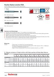
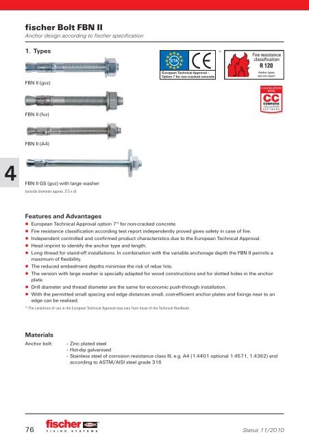
1. Types<br />
<strong>FBN</strong> <strong>II</strong> (gvz)<br />
<strong>FBN</strong> <strong>II</strong> (fvz)<br />
<strong>FBN</strong> <strong>II</strong> (A4)<br />
<strong>FBN</strong> <strong>II</strong> GS (gvz) with large washer<br />
(outside diameter approx. 3.5 x d)<br />
Features and Advantages<br />
▯ European Technical Approval option 7* ) for non-cracked concrete.<br />
▯ Fire resistance classifi cation according test report independently proved gives safety in case of fi re.<br />
▯ Independent controlled and confi rmed product characteristics due to the European Technical Approval.<br />
▯ Head imprint to identify the anchor type and length.<br />
▯ Long thread for stand-off installations. In combination with the variable anchorage depth the <strong>FBN</strong> <strong>II</strong> permits a<br />
maximum of fl exibility.<br />
▯ The reduced embedment depths minimise the risk of rebar hits.<br />
▯ The version with large washer is specially adapted for wood constructions and for slotted holes in the anchor<br />
plate.<br />
▯ Drill diameter and thread diameter are the same for economic push-through installation.<br />
▯ With the permitted small spacing and edge distances small, cost-effi cient anchor plates and fi xings near to an<br />
edge can be realised.<br />
* ) The conditions of use in the European Technical Approval may vary from those of the Technical Handbook.<br />
Materials<br />
Anchor bolt: - Zinc plated steel<br />
- Hot-dip galvanised<br />
- Stainless steel of corrosion resistance class <strong>II</strong>I, e.g. A4 (1.4401 optional 1.4571, 1.4362) and<br />
according to ASTM/AISI steel grade 316<br />
76<br />
* )<br />
Status 11/2010
fi scher <strong>Bolt</strong> <strong>FBN</strong> <strong>II</strong><br />
Anchor design according to fi scher specifi cation<br />
2. Ultimate resistance of single anchors with large spacing and large edge distance<br />
Mean values<br />
Anchor type <strong>FBN</strong> <strong>II</strong> M6 <strong>FBN</strong> <strong>II</strong> M8 <strong>FBN</strong> <strong>II</strong> M8 <strong>FBN</strong> <strong>II</strong> M10 <strong>FBN</strong> <strong>II</strong> M10 <strong>FBN</strong> <strong>II</strong> M12<br />
gvz A4 gvz fvz A4 gvz fvz A4 gvz fvz A4 gvz fvz A4 gvz fvz A4<br />
hef non-cracked concrete<br />
30 30 30 30 30 40 40 40 40 40 40 50 50 50 50 50 50<br />
Tension C 20/25 Nu [kN] 9.0 9.0 9.9 8.2 9.9 16.1 15.0 16.1 15.8 16.0 15.8 22.9 20.0 22.9 23.6 22.4 23.6<br />
C 50/60 Nu [kN] 9.0 9.0 13.7 13.7 15.5 13.7 15.0 16.1 21.8 21.8 25.4 22.9 21.8 25.4 33.2 33.2 36.0<br />
Shear ≧ C 20/25 Vu [kN] 4.7 5.3 11.0 11.0 12.8 11.0 11.0 12.8 17.0 17.0 20.3 17.0 17.0 20.3 25.0 25.0 27.4<br />
Anchor type <strong>FBN</strong> <strong>II</strong> M12 <strong>FBN</strong> <strong>II</strong> M16 <strong>FBN</strong> <strong>II</strong> M16 <strong>FBN</strong> <strong>II</strong> M20 <strong>FBN</strong> <strong>II</strong> M20<br />
gvz fvz A4 gvz fvz A4 gvz fvz A4 gvz fvz A4 gvz fvz A4<br />
hef non-cracked concrete<br />
65 65 65 65 65 65 80 80 80 80 80 80 105 105 105<br />
Tension C 20/25 Nu [kN] 35.7 31.3 35.7 37.6 35.8 37.6 47.0 44.5 47.0 55.0 44.7 55.0 76.8 64.8 76.8<br />
C 50/60 Nu [kN] 35.7 33.2 36.0 54.8 54.8 54.8 62.3 62.3 67.5 74.8 74.8 74.8 107.3 107.3 110.9<br />
Shear ≧ C 20/25 Vu [kN] 25.0 25.0 27.4 47.0 47.0 51.0 47.0 47.0 51.0 67.0 67.0 86.0 67.0 67.0 86.0<br />
3. Characteristic, design and recommended resistance of single anchors with<br />
large spacing and large edge distance<br />
3.1 Characteristic resistance<br />
Anchor type <strong>FBN</strong> <strong>II</strong> M6 <strong>FBN</strong> <strong>II</strong> M8 <strong>FBN</strong> <strong>II</strong> M8 <strong>FBN</strong> <strong>II</strong> M10 <strong>FBN</strong> <strong>II</strong> M10 <strong>FBN</strong> <strong>II</strong> M12<br />
gvz A4 gvz fvz A4 gvz fvz A4 gvz fvz A4 gvz fvz A4 gvz fvz A4<br />
hef non-cracked concrete<br />
30 30 30 30 30 40 40 40 40 40 40 50 50 50 50 50 50<br />
Tension C 20/25 NRk [kN] 6.0 6.0 6.0 6.0 6.0 12.8 12.0 12.8 12.8 12.8 12.8 17.9 16.0 17.9 17.9 17.9 17.9<br />
C 50/60 NRk [kN] 6.1 9.3 9.3 9.3 9.3 16.0 16.0 16.5 19.8 19.8 19.8 25.0 24.8 27.7 27.7 27.7 27.7<br />
Shear ≧ C 20/25 VRk [kN] 4.7 5.3 8.3 8.3 8.3 12.8 12.8 12.8 12.8 12.8 12.8 17.9 17.9 17.9 17.9 17.9 17.9<br />
Anchor type <strong>FBN</strong> <strong>II</strong> M12 <strong>FBN</strong> <strong>II</strong> M16 <strong>FBN</strong> <strong>II</strong> M16 <strong>FBN</strong> <strong>II</strong> M20 <strong>FBN</strong> <strong>II</strong> M20<br />
gvz fvz A4 gvz fvz A4 gvz fvz A4 gvz fvz A4 gvz fvz A4<br />
hef non-cracked concrete<br />
65 65 65 65 65 65 80 80 80 80 80 80 105 105 105<br />
Tension C 20/25 NRk [kN] 26.5 25.0 26.5 26.5 26.5 26.5 36.1 36.1 36.1 36.1 36.1 36.1 54.3 54.3 54.3<br />
C 50/60 NRk [kN] 36.0 36.0 41.0 41.0 41.0 41.0 56.0 56.0 56.0 56.0 56.0 56.0 84.2 84.2 84.2<br />
Shear ≧ C 20/25 VRk [kN] 25.0 25.0 27.4 52.9 52.9 52.9 47.0 47.0 51.0 72.3 72.3 72.3 67.0 67.0 86.0<br />
3.2 Design resistance<br />
Anchor type <strong>FBN</strong> <strong>II</strong> M6 <strong>FBN</strong> <strong>II</strong> M8 <strong>FBN</strong> <strong>II</strong> M8 <strong>FBN</strong> <strong>II</strong> M10 <strong>FBN</strong> <strong>II</strong> M10 <strong>FBN</strong> <strong>II</strong> M12<br />
gvz A4 gvz fvz A4 gvz fvz A4 gvz fvz A4 gvz fvz A4 gvz fvz A4<br />
hef non-cracked concrete<br />
30 30 30 30 30 40 40 40 40 40 40 50 50 50 50 50 50<br />
Tension C 20/25 NRd [kN] 4.0 4.0 4.0 4.0 4.0 8.5 8.0 8.5 8.5 8.5 8.5 11.9 10.7 11.9 11.9 11.9 11.9<br />
C 50/60 NRd [kN] 4.1 6.2 6.2 6.2 6.2 11.4 11.4 11.8 13.2 13.2 13.2 17.9 16.5 18.4 18.4 18.4 18.4<br />
Shear ≧ C 20/25 VRd [kN] 3.8 4.2 5.5 5.5 5.5 8.5 8.5 8.5 8.5 8.5 8.5 11.9 11.9 11.9 11.9 11.9 11.9<br />
Anchor type <strong>FBN</strong> <strong>II</strong> M12 <strong>FBN</strong> <strong>II</strong> M16 <strong>FBN</strong> <strong>II</strong> M16 <strong>FBN</strong> <strong>II</strong> M20 <strong>FBN</strong> <strong>II</strong> M20<br />
gvz fvz A4 gvz fvz A4 gvz fvz A4 gvz fvz A4 gvz fvz A4<br />
hef non-cracked concrete<br />
65 65 65 65 65 65 80 80 80 80 80 80 105 105 105<br />
Tension C 20/25 NRd [kN] 17.6 16.7 17.6 17.6 17.6 17.6 24.1 24.1 24.1 24.1 24.1 24.1 36.2 36.2 36.2<br />
C 50/60 NRd [kN] 25.7 25.7 27.3 27.3 27.3 27.3 37.3 37.3 37.3 37.3 37.3 37.3 56.1 56.1 56.1<br />
Shear ≧ C 20/25 VRd [kN] 20.0 20.0 21.9 35.3 35.3 35.3 37.6 37.6 40.8 48.2 48.2 48.2 53.6 53.6 68.8<br />
Status 11/2010<br />
77<br />
4
4<br />
fi scher <strong>Bolt</strong> <strong>FBN</strong> <strong>II</strong><br />
Anchor design according to fi scher specifi cation<br />
3.3 Recommended resistance 1)<br />
Anchor type <strong>FBN</strong> <strong>II</strong> M6 <strong>FBN</strong> <strong>II</strong> M8 <strong>FBN</strong> <strong>II</strong> M8 <strong>FBN</strong> <strong>II</strong> M10 <strong>FBN</strong> <strong>II</strong> M10 <strong>FBN</strong> <strong>II</strong> M12<br />
gvz A4 gvz fvz A4 gvz fvz A4 gvz fvz A4 gvz fvz A4 gvz fvz A4<br />
hef non-cracked concrete<br />
30 30 30 30 30 40 40 40 40 40 40 50 50 50 50 50 50<br />
Tension C 20/25 NR [kN] 2.9 2.9 2.9 2.9 2.9 6.1 5.7 6.1 6.1 6.1 6.1 8.5 7.6 8.5 8.5 8.5 8.5<br />
C 50/60 NR [kN] 2.9 4.4 4.4 4.4 4.4 8.2 8.2 8.4 9.4 9.4 9.4 12.8 11.8 13.2 13.2 13.2 13.2<br />
Shear ≧ C 20/25 VR [kN] 2.7 3.0 4.0 4.0 4.0 6.1 6.1 6.1 6.1 6.1 6.1 8.5 8.5 8.5 8.5 8.5 8.5<br />
Anchor type <strong>FBN</strong> <strong>II</strong> M12 <strong>FBN</strong> <strong>II</strong> M16 <strong>FBN</strong> <strong>II</strong> M16 <strong>FBN</strong> <strong>II</strong> M20 <strong>FBN</strong> <strong>II</strong> M20<br />
gvz fvz A4 gvz fvz A4 gvz fvz A4 gvz fvz A4 gvz fvz A4<br />
hef non-cracked concrete<br />
65 65 65 65 65 65 80 80 80 80 80 80 105 105 105<br />
Tension C 20/25 NR [kN] 12.6 11.9 12.6 12.6 12.6 12.6 17.2 17.2 17.2 17.2 17.2 17.2 25.9 25.9 25.9<br />
C 50/60 NR [kN] 18.4 18.4 19.5 19.5 19.5 19.5 26.7 26.7 26.7 26.7 26.7 26.7 40.1 40.1 40.1<br />
Shear ≧ C 20/25 VR [kN] 14.3 14.3 15.7 25.2 25.2 25.2 26.9 26.9 29.1 34.4 34.4 34.4 38.3 38.3 49.1<br />
1) Material safety factors �M and safety factor for action �L = 1.4 are included. Material safety factor �M depends on failure mode of the anchor.<br />
4. Calculation of tension resistance<br />
The decisive design resistance in tension is the lowest value of following failure modes:<br />
Steel failure: NRd,s Pull-out/pull-through failure: NRd,p = N0 Rd,p ⋅ fb,N Concrete cone failure: NRd,c = N0 Rd,c ⋅ fb,N ⋅ fs1 ⋅ fs2 ⋅ fs3 ⋅ fc1,A ⋅ fc1,B ⋅ fc2 Concrete splitting failure: NRd,sp = N0 Rd,c ⋅ fb,N ⋅ fs1,sp ⋅ fs2,sp ⋅ fs3,sp ⋅ fc1,sp,A ⋅ fc1,sp,B ⋅ fc2,sp ⋅ fh 4.1 Steel failure of the highest loaded anchor<br />
Design resistance of single anchor<br />
Anchor type <strong>FBN</strong> <strong>II</strong> M6 <strong>FBN</strong> <strong>II</strong> M8 <strong>FBN</strong> <strong>II</strong> M8 <strong>FBN</strong> <strong>II</strong> M10 <strong>FBN</strong> <strong>II</strong> M10 <strong>FBN</strong> <strong>II</strong> M12<br />
gvz A4 gvz fvz A4 gvz fvz A4 gvz fvz A4 gvz fvz A4 gvz fvz A4<br />
hef 30 30 30 30 30 40 40 40 40 40 40 50 50 50 50 50 50<br />
Design resistance NRd,s [kN] 4.1 7.1 11.4 11.4 11.8 11.4 11.4 11.8 17.9 17.9 19.4 17.9 17.9 19.4 25.7 25.7 29.7<br />
Anchor type <strong>FBN</strong> <strong>II</strong> M12 <strong>FBN</strong> <strong>II</strong> M16 <strong>FBN</strong> <strong>II</strong> M16 <strong>FBN</strong> <strong>II</strong> M20 <strong>FBN</strong> <strong>II</strong> M20<br />
gvz fvz A4 gvz fvz A4 gvz fvz A4 gvz fvz A4 gvz fvz A4<br />
hef 65 65 65 65 65 65 80 80 80 80 80 80 105 105 105<br />
Design resistance NRd,s [kN] 25.7 25.7 29.7 44.7 44.7 55.7 44.7 44.7 55.7 71.3 71.3 74.0 71.3 71.3 74.0<br />
4.2 Pull-out/pull-through failure of the highest loaded anchor<br />
N Rd,p = N 0<br />
Rd,p ⋅ f b,N<br />
Design resistance of single anchor<br />
Anchor type <strong>FBN</strong> <strong>II</strong> M6 <strong>FBN</strong> <strong>II</strong> M8 <strong>FBN</strong> <strong>II</strong> M8 <strong>FBN</strong> <strong>II</strong> M10 <strong>FBN</strong> <strong>II</strong> M10 <strong>FBN</strong> <strong>II</strong> M12<br />
gvz A4 gvz fvz A4 gvz fvz A4 gvz fvz A4 gvz fvz A4 gvz fvz A4<br />
hef non-cracked concrete<br />
30 30 30 30 30 40 40 40 40 40 40 50 50 50 50 50 50<br />
Design resistance N0 Rd,p [kN] 4.0 4.0 4.0 4.0 4.0 8.5 8.0 8.5 8.5 8.5 8.5 11.9 10.7 11.9 11.9 11.9 11.9<br />
Anchor type <strong>FBN</strong> <strong>II</strong> M12 <strong>FBN</strong> <strong>II</strong> M16 <strong>FBN</strong> <strong>II</strong> M16 <strong>FBN</strong> <strong>II</strong> M20 <strong>FBN</strong> <strong>II</strong> M20<br />
gvz fvz A4 gvz fvz A4 gvz fvz A4 gvz fvz A4 gvz fvz A4<br />
hef non-cracked concrete<br />
65 65 65 65 65 65 80 80 80 80 80 80 105 105 105<br />
Design resistance N0 Rd.p [kN] 17.6 16.7 17.6 17.6 17.6 17.6 24.1 24.1 24.1 24.1 24.1 24.1 36.2 36.2 36.2<br />
78<br />
Status 11/2010
fi scher <strong>Bolt</strong> <strong>FBN</strong> <strong>II</strong><br />
Anchor design according to fi scher specifi cation<br />
4.3 Concrete cone failure and splitting of the most unfavourable anchor<br />
Concrete cone failure: NRd,c = N0 Rd,c ⋅ fb,N ⋅ fs1 ⋅ fs2 ⋅ fs3 ⋅ fc1, A ⋅ fc1,B ⋅ fc2 Concrete splitting failure: NRd,sp = N0 Rd,c ⋅ fb,N ⋅ fs1,sp ⋅ fs2,sp ⋅ fs3,sp ⋅ fc1,sp,A ⋅ fc1,sp,B ⋅ fc2,sp ⋅ fh Status 11/2010<br />
Proof of splitting failure is only necessary if all of the following conditions are met:<br />
• non-cracked concrete<br />
• c cr,sp > c cr, N<br />
• c < 1.2 c cr,sp<br />
Design resistance of single anchor<br />
Anchor type <strong>FBN</strong> <strong>II</strong> M6 <strong>FBN</strong> <strong>II</strong> M8 <strong>FBN</strong> <strong>II</strong> M8 <strong>FBN</strong> <strong>II</strong> M10 <strong>FBN</strong> <strong>II</strong> M10 <strong>FBN</strong> <strong>II</strong> M12<br />
hef non-cracked concrete<br />
30 30 40 40 50 50<br />
Design resistance N0 Rd,c [kN] 5.5 5.5 8.5 8.5 11.9 11.9<br />
Anchor type <strong>FBN</strong> <strong>II</strong> M12 <strong>FBN</strong> <strong>II</strong> M16 <strong>FBN</strong> <strong>II</strong> M16 <strong>FBN</strong> <strong>II</strong> M20 <strong>FBN</strong> <strong>II</strong> M20<br />
hef non-cracked concrete<br />
65 65 80 80 105<br />
Design resistance N0 Rd,c [kN] 17.6 17.6 24.1 24.1 36.2<br />
4.3.1 Infl uence of concrete strength for tension<br />
����<br />
�<br />
���������<br />
��<br />
�<br />
�������� ��<br />
Concrete strength class C 12/15 C 16/20 C 20/25 C 25/30 C 30/37 C 35/45 C 40/50 C 45/55 C 50/60<br />
cylinder compressive strength f ck,cyl [N/mm 2 ] 12 16 20 25 30 35 40 45 50<br />
cube compressive strength f ck,cube [N/mm 2 ] 15 20 25 30 37 45 50 55 60<br />
infl uence factor f b,N [-] 0.77 0.89 1.00 1.10 1.22 1.34 1.41 1.48 1.55<br />
4.3.2 Concrete cone failure<br />
Characteristic edge distance and spacing for design<br />
Anchor type <strong>FBN</strong> <strong>II</strong> M6 <strong>FBN</strong> <strong>II</strong> M8 <strong>FBN</strong> <strong>II</strong> M8 <strong>FBN</strong> <strong>II</strong> M10 <strong>FBN</strong> <strong>II</strong> M10 <strong>FBN</strong> <strong>II</strong> M12<br />
hef 30 30 40 40 50 50<br />
scr, N [mm] 90 90 120 120 150 150<br />
ccr, N [mm] 45 45 60 60 75 75<br />
Anchor type <strong>FBN</strong> <strong>II</strong> M12 <strong>FBN</strong> <strong>II</strong> M16 <strong>FBN</strong> <strong>II</strong> M16 <strong>FBN</strong> <strong>II</strong> M20 <strong>FBN</strong> <strong>II</strong> M20<br />
hef 65 65 80 80 105<br />
scr, N [mm] 195 195 240 240 315<br />
ccr, N [mm] 98 98 120 120 158<br />
79<br />
4
4<br />
fi scher <strong>Bolt</strong> <strong>FBN</strong> <strong>II</strong><br />
Anchor design according to fi scher specifi cation<br />
4.3.2.1 Infl uence of spacing / concrete cone failure<br />
�<br />
���<br />
��� ����� �������������<br />
� �<br />
����<br />
�<br />
�<br />
�<br />
�<br />
�<br />
�<br />
� � ��� �<br />
�<br />
s/s cr,N 0.1 0.15 0.2 0.25 0.3 0.35 0.4 0.45 0.5 0.55 0.6 0.65 0.7 0.75 0.8 0.85 0.9 0.95 ≧1.0<br />
f s1 0.55 0.58 0.6 0.63 0.65 0.68 0.7 0.73 0.75 0.78 0.8 0.83 0.85 0.88 0.9 0.93 0.95 0.98 1.0<br />
4.3.2.2 Infl uence of edge distance / concrete cone failure<br />
�<br />
80<br />
�<br />
�������������������������������<br />
�<br />
�<br />
���� � �����<br />
��� ����� �������������<br />
����<br />
� �<br />
����<br />
�<br />
�<br />
�<br />
�<br />
�<br />
�<br />
� �<br />
�<br />
c/c cr,N 0.1 0.15 0.2 0.25 0.3 0.35 0.4 0.45 0.5 0.55 0.6 0.65 0.7 0.75 0.8 0.85 0.9 0.95 ≧1.0<br />
f c1,A 0.73 0.75 0.76 0.78 0.79 0.81 0.82 0.84 0.85 0.87 0.88 0.9 0.91 0.93 0.94 0.96 0.97 0.99 1.0<br />
f c1,B<br />
f c2<br />
0.55 0.58 0.6 0.63 0.65 0.68 0.7 0.73 0.75 0.78 0.8 0.83 0.85 0.88 0.9 0.93 0.95 0.98 1.0<br />
4.3.3 Concrete splitting failure<br />
Characteristic edge distance and spacing for design<br />
Anchor type <strong>FBN</strong> <strong>II</strong> M6 <strong>FBN</strong> <strong>II</strong> M8 <strong>FBN</strong> <strong>II</strong> M8 <strong>FBN</strong> <strong>II</strong> M10 <strong>FBN</strong> <strong>II</strong> M10 <strong>FBN</strong> <strong>II</strong> M12<br />
hef 30 30 40 40 50 50<br />
scr, sp [mm] 200 190 190 200 200 290<br />
ccr, sp [mm] 100 95 95 100 100 145<br />
hmin [mm] 100 100 100 100 100 100<br />
Anchor type <strong>FBN</strong> <strong>II</strong> M12 <strong>FBN</strong> <strong>II</strong> M16 <strong>FBN</strong> <strong>II</strong> M16 <strong>FBN</strong> <strong>II</strong> M20 <strong>FBN</strong> <strong>II</strong> M20<br />
hef 65 65 80 80 105<br />
scr, sp [mm] 290 350 350 370 370<br />
ccr, sp [mm] 145 175 175 185 185<br />
hmin [mm] 120 120 160 160 200<br />
4.3.3.1 Infl uence of spacing / Concrete splitting failure<br />
�<br />
������<br />
������ ����� �������������<br />
� �<br />
�����<br />
�<br />
�<br />
�<br />
�<br />
�<br />
�<br />
������ � � �<br />
�<br />
s/s cr,sp 0.1 0.15 0.2 0.25 0.3 0.35 0.4 0.45 0.5 0.55 0.6 0.65 0.7 0.75 0.8 0.85 0.9 0.95 ≧1.0<br />
f s,sp 0.55 0.58 0.6 0.63 0.65 0.68 0.7 0.73 0.75 0.78 0.8 0.83 0.85 0.88 0.9 0.93 0.95 0.98 1.0<br />
4.3.3.2 Infl uence of edge distance / Concrete splitting failure<br />
�<br />
��������<br />
� ��������������������������������<br />
������<br />
�<br />
��������<br />
������ ����� �������������<br />
� �<br />
�����<br />
�<br />
�<br />
�<br />
�<br />
�<br />
�<br />
� �<br />
�<br />
c/c cr,sp 0.1 0.15 0.2 0.25 0.3 0.35 0.4 0.45 0.5 0.55 0.6 0.65 0.7 0.75 0.8 0.85 0.9 0.95 ≧1.0<br />
f c1,sp,A 0.73 0.75 0.76 0.78 0.79 0.81 0.82 0.84 0.85 0.87 0.88 0.9 0.91 0.93 0.94 0.96 0.97 0.99 1.0<br />
f c1,sp,B<br />
f c2,sp<br />
0.55 0.58 0.6 0.63 0.65 0.68 0.7 0.73 0.75 0.78 0.8 0.83 0.85 0.88 0.9 0.93 0.95 0.98 1.0<br />
Status 11/2010
fi scher <strong>Bolt</strong> <strong>FBN</strong> <strong>II</strong><br />
Anchor design according to fi scher specifi cation<br />
4.3.3.3 Infl uence of concrete thickness / Concrete splitting failure<br />
�<br />
�� �����<br />
� �<br />
���<br />
�<br />
�<br />
�<br />
�<br />
�<br />
� �<br />
�<br />
�<br />
h/h min 1.0 1.05 1.1 1.15 1.2 1.25 1.3 1.35 1.4 1.45 1.5 1.55 1.6 1.65 1.7 1.75 1.8 ≧1.84<br />
f h 1.0 1.03 1.07 1.1 1.13 1.16 1.19 1.22 1.25 1.28 1.31 1.34 1.37 1.4 1.42 1.45 1.48 1.5<br />
5. Calculation of shear resistance<br />
The decisive design resistance in shear is the lowest value of the following failure modes:<br />
Steel failure: VRd,s Pryout failure: VRd,cp = NRd,c ⋅ k<br />
Concrete edge failure: VRd,c = V0 Rd,c ⋅ fb,V ⋅ fα,V ⋅ fs1,V ⋅ fs2,V ⋅ fc2,V ⋅ fh,V ⋅ fm 5.1 Steel failure of the highest loaded anchor<br />
Design resistance of single anchor<br />
Anchor type <strong>FBN</strong> <strong>II</strong> M6 <strong>FBN</strong> <strong>II</strong> M8 <strong>FBN</strong> <strong>II</strong> M8 <strong>FBN</strong> <strong>II</strong> M10 <strong>FBN</strong> <strong>II</strong> M10 <strong>FBN</strong> <strong>II</strong> M12<br />
gvz A4 gvz fvz A4 gvz fvz A4 gvz fvz A4 gvz fvz A4 gvz fvz A4<br />
hef 30 30 40 40 50 50<br />
Design resistance VRd,s [kN] 3.8 4.2 8.8 10.2 8.8 10.2 13.6 16.2 13.6 16.2 20.0 21.9<br />
Anchor type <strong>FBN</strong> <strong>II</strong> M12 <strong>FBN</strong> <strong>II</strong> M16 <strong>FBN</strong> <strong>II</strong> M16 <strong>FBN</strong> <strong>II</strong> M20 <strong>FBN</strong> <strong>II</strong> M20<br />
gvz fvz A4 gvz fvz A4 gvz fvz A4 gvz fvz A4 gvz fvz A4<br />
hef 65 65 80 80 105<br />
Design resistance VRd,s [kN] 20.0 21.9 37.6 40.8 37.6 40.8 53.6 68.8 53.6 68.8<br />
5.2 Pryout failure of the most unfavourable anchor<br />
VRd,cp = NRd,c ⋅ k<br />
k-factor<br />
Anchor type <strong>FBN</strong> <strong>II</strong> M6 <strong>FBN</strong> <strong>II</strong> M8 <strong>FBN</strong> <strong>II</strong> M8 <strong>FBN</strong> <strong>II</strong> M10 <strong>FBN</strong> <strong>II</strong> M10 <strong>FBN</strong> <strong>II</strong> M12<br />
hef 30 30 40 40 50 50<br />
k 1.0 1.0 1.0 1.0 1.0 1.0<br />
Anchor type <strong>FBN</strong> <strong>II</strong> M12 <strong>FBN</strong> <strong>II</strong> M16 <strong>FBN</strong> <strong>II</strong> M16 <strong>FBN</strong> <strong>II</strong> M20 <strong>FBN</strong> <strong>II</strong> M20<br />
hef 65 65 80 80 105<br />
k 2.0 2.0 2.0 2.0 2.0<br />
Status 11/2010<br />
81<br />
4
4<br />
fi scher <strong>Bolt</strong> <strong>FBN</strong> <strong>II</strong><br />
Anchor design according to fi scher specifi cation<br />
5.3 Concrete edge failure of the most unfavourable anchor<br />
V Rd,c = V O<br />
Rd,c ⋅ f b,V ⋅ f α,V ⋅ f s1,V ⋅ f s2,V ⋅ f c2,V ⋅ f h,V ⋅ f m<br />
Proof of concrete edge failure is only necessary, if the following condition is met:<br />
• c < max (10 hef ; 60 d) with d = nominal anchor diameter<br />
Design resistance of single anchor in concrete C 20/25 dependent on edge distance c1 edge<br />
V<br />
distance<br />
0<br />
Rd,c [kN]<br />
<strong>FBN</strong> <strong>II</strong> <strong>FBN</strong> <strong>II</strong> M8 <strong>FBN</strong> <strong>II</strong> M8 <strong>FBN</strong> <strong>II</strong> <strong>FBN</strong> <strong>II</strong> M10 <strong>FBN</strong> <strong>II</strong> <strong>FBN</strong> <strong>II</strong> <strong>FBN</strong> <strong>II</strong> <strong>FBN</strong> <strong>II</strong> M16 <strong>FBN</strong> <strong>II</strong> M20 <strong>FBN</strong> <strong>II</strong><br />
M6<br />
M10<br />
M12 M12 M16<br />
M20<br />
gvz/fvz A4 gvz/fvz A4 gvz/fvz A4 gvz/fvz A4 gvz/fvz A4<br />
hef edge<br />
30 30 30 40 40 40 50 50 50 65 65 80 80 80 80 105<br />
distance<br />
[mm]<br />
non-cracked concrete<br />
40 3.1 3.3<br />
45 3.6 3.6 3.8 3.8<br />
50 4.2 4.2 4.4 4.4 4.7<br />
55 4.8 4.8 5.0 5.0 5.4 5.4<br />
60 5.4 5.4 5.6 5.6 6.0 6.0<br />
65 6.0 6.0 6.3 6.3 6.7 6.7<br />
70 6.7 6.7 7.0 7.0 7.4 7.4 8.0<br />
75 7.4 7.4 7.7 7.7 8.1 8.1 8.7<br />
80 8.1 8.1 8.4 8.4 8.6 8.9 8.9 9.5 10.4<br />
85 8.8 8.8 9.1 9.1 9.3 9.7 9.7 10.3 11.2<br />
90 9.5 9.5 9.8 9.8 10.1 10.4 10.4 11.2 12.1 12.1<br />
95 10.2 10.2 10.6 10.6 10.9 11.2 11.2 12.0 13.0 13.0<br />
100 10.7 11.0 11.0 11.4 11.4 11.7 12.1 12.1 12.3 12.8 13.9 13.9<br />
110 12.3 12.6 12.6 13.0 13.0 13.3 13.7 13.7 14.0 14.6 15.8 15.8<br />
120 13.9 14.2 14.2 14.7 14.7 15.0 15.5 15.5 15.8 16.4 17.0 17.7 17.7 18.2 18.2 19.3<br />
130 15.5 15.9 15.9 16.4 16.4 16.8 17.3 17.3 17.6 18.3 19.0 19.7 19.7 20.3 20.3 21.4<br />
140 17.3 17.7 17.7 18.2 18.2 18.6 19.2 19.2 19.5 20.3 21.0 21.7 21.7 22.4 22.4 23.5<br />
150 19.0 19.5 19.5 20.1 20.1 20.5 21.1 21.1 21.5 22.3 23.0 23.8 23.8 24.5 24.5 25.8<br />
160 20.9 21.4 21.4 22.0 22.0 22.5 23.1 23.1 23.5 24.3 25.1 26.0 26.0 26.7 26.7 28.1<br />
180 24.7 25.2 25.2 26.0 26.0 26.5 27.2 27.2 27.7 28.6 29.5 30.4 30.4 31.3 31.3 32.8<br />
200 28.7 29.3 29.3 30.1 30.1 30.7 31.5 31.5 32.0 33.1 34.1 35.1 35.1 36.1 36.1 37.7<br />
250 39.5 40.3 40.3 41.4 41.4 42.1 43.0 43.0 43.7 45.1 46.3 47.6 47.6 48.8 48.8 50.8<br />
300 51.4 52.3 52.3 53.6 53.6 54.5 55.7 55.7 56.5 58.1 59.7 61.2 61.2 62.6 62.6 65.1<br />
350 64.2 65.3 65.3 66.8 66.8 67.9 69.3 69.3 70.2 72.1 73.9 75.8 75.8 77.4 77.4 80.3<br />
400 79.2 79.2 80.9 80.9 82.1 83.7 83.7 84.8 87.0 89.1 91.2 91.2 93.1 93.1 96.4<br />
450 93.8 93.8 95.8 95.8 97.2 99.0 99.0 100.3 102.7 105.1 107.5 107.5 109.6 109.6 113.3<br />
500 109.2 109.2 111.5 111.5 113.0 115.0 115.0 116.5 119.2 121.9 124.5 124.5 126.9 126.9 131.0<br />
550 129.6 131.8 131.8 133.4 136.5 139.4 142.4 142.4 145.0 145.0 149.5<br />
600 146.8 149.3 149.3 151.1 154.4 157.7 160.9 160.9 163.8 163.8 168.7<br />
650 164.7 167.5 167.5 169.4 173.1 176.6 180.1 180.1 183.2 183.2 188.6<br />
700 188.3 192.3 196.1 199.9 199.9 203.3 203.3 209.1<br />
750 207.9 212.2 216.3 220.4 220.4 224.1 224.1 230.3<br />
800 237.1 241.5 241.5 245.4 245.4 252.1<br />
850 258.5 263.1 263.1 267.3 267.3 274.4<br />
900 280.4 285.3 285.3 289.8 289.8 297.4<br />
950 302.9 308.1 308.1 312.9 312.9 320.9<br />
1000 325.9 331.4 331.4 336.4 336.4 344.9<br />
1100 385.2 385.2 394.5<br />
1200 435.9 435.9 446.1<br />
82<br />
Status 11/2010
fi scher <strong>Bolt</strong> <strong>FBN</strong> <strong>II</strong><br />
Anchor design according to fi scher specifi cation<br />
5.3.1 Infl uence of concrete strength for shear<br />
����<br />
�<br />
���������<br />
�<br />
��<br />
Status 11/2010<br />
�������� ��<br />
Concrete strength class C 12/15 C 16/20 C 20/25 C 25/30 C 30/37 C 35/45 C 40/50 C 45/55 C 50/60<br />
cylinder compressive strength f ck,cyl [N/mm 2 ] 12 16 20 25 30 35 40 45 50<br />
cube compressive strength f ck,cube [N/mm 2 ] 15 20 25 30 37 45 50 55 60<br />
infl uence factor f b,V [-] 0.77 0.89 1.00 1.10 1.22 1.34 1.41 1.48 1.55<br />
5.3.2 Infl uence of load direction<br />
�<br />
���� �������������������������������������������������������<br />
���������������� � ����������������<br />
� ������ �<br />
���<br />
0 10 20 30 40 50 60 70 80 90<br />
fα,V 1.00 1.01 1.05 1.13 1.24 1.40 1.64 1.97 2.32 2.50<br />
For angle α ≧ 90° the component of the shear load acting away from the edge may be neglected and the proof may be done with the component of<br />
the load acting parallel to the edge.<br />
5.3.3 Infl uence of spacing<br />
�<br />
����� � ����� � �<br />
�<br />
� �<br />
���������������<br />
�� �<br />
s/c1 0.5 0.6 0.7 0.8 0.9 1.0 1.2 1.4 1.6 1.8 2.0 2.2 2.4 2.6 2.8 ≧3.0<br />
fs1,V 0.58 0.6 0.62 0.63 0.65 0.67 0.7 0.73 0.77 0.8 0.83 0.87 0.9 0.93 0.97 1.0<br />
5.3.4 Infl uence of edge distance<br />
Distance to second edge; c 1 < c 2<br />
�<br />
�����<br />
�<br />
�<br />
�<br />
���������������������������������������<br />
�<br />
������� �<br />
�<br />
�<br />
�<br />
�<br />
�<br />
�<br />
�<br />
�<br />
�<br />
�<br />
�<br />
�<br />
�<br />
�<br />
� � �<br />
� � �<br />
� � � �� c2 /c1 1.0 1.1 1.2 1.3 1.4 ≧1.5<br />
fc2,V 0.75 0.8 0.85 0.9 0.95 1.0<br />
5.3.5 Infl uence of member thickness<br />
�<br />
���� ������� �<br />
�<br />
�<br />
�<br />
�<br />
�<br />
�<br />
� ���<br />
������������������������������������<br />
�<br />
h/c1 0.1 0.2 0.3 0.4 0.5 0.6 0.7 0.8 0.9 1.0 1.2 1.3 1.4 ≧1.5<br />
fh,V 0.26 0.37 0.45 0.52 0.58 0.63 0.68 0.73 0.77 0.82 0.89 0.93 0.97 1.0<br />
5.3.6 Infl uence of group with ≧ 4 anchors in a row at the edge<br />
f m<br />
s/c1 0.25 0.5 1.0 ≧2.0<br />
fm 0.3 0.5 0.75 1.0<br />
83<br />
4
4<br />
fi scher <strong>Bolt</strong> <strong>FBN</strong> <strong>II</strong><br />
Anchor design according to fi scher specifi cation<br />
6. Summary of required proof:<br />
6.1 Tension: N Sd ≦ N Rd = lowest value of N Rd,s ; N Rd,p ; N Rd,c ; N Rd,sp<br />
6.2 Shear: V Sd ≦ V Rd = lowest value of V Rd,s ; V Rd,cp ; V Rd,c<br />
6.3 Combined tension and shear load:<br />
7. Installation details<br />
84<br />
� � �� ��<br />
� �<br />
���<br />
���<br />
���<br />
NSd ; VSd = tension/shear component of the design load acting on<br />
the most unfavourable single anchor<br />
NRd ; VRd = tension/shear design resistance including safety factors<br />
of the most unfavourable single anchor<br />
Status 11/2010
fi scher <strong>Bolt</strong> <strong>FBN</strong> <strong>II</strong><br />
Anchor design according to fi scher specifi cation<br />
8. Anchor characteristics<br />
Anchor type <strong>FBN</strong> <strong>II</strong> M6 <strong>FBN</strong> <strong>II</strong> M8 <strong>FBN</strong> <strong>II</strong> M8 <strong>FBN</strong> <strong>II</strong> M10 <strong>FBN</strong> <strong>II</strong> M10 <strong>FBN</strong> <strong>II</strong> M12<br />
gvz A4 gvz fvz A4 gvz fvz A4 gvz fvz A4 gvz fvz A4 gvz fvz A4<br />
h ef [mm] 30 30 40 40 50 50<br />
diameter of thread M6 M8 M8 M10 M10 M12<br />
nominal drill hole diameter d 0 [mm] 6 8 8 10 10 12<br />
drill depth h 1 [mm] 40 46 56 58 68 70<br />
drill hole depth for<br />
through fixing<br />
td [mm] td = h1 + tfi x<br />
clearance-hole in fixture<br />
to be attached<br />
df [mm] ≦ 7 ≦ 9 ≦ 9 ≦ 12 ≦ 12 ≦ 14<br />
wrench size SW [mm] 10 13 13 17 17 19<br />
required torque Tinst [Nm] 4 15 10 15 10 30 20 30 20 50 35<br />
minimum thickness of<br />
concrete member<br />
hmin [mm] 100 100 100 100 100 100<br />
miminum spacing smin [mm] 50 40 50 40 50 50 70 70<br />
minimum edge distance c min [mm] 100 40 45 40 45 80 50 55 100<br />
Anchor type <strong>FBN</strong> <strong>II</strong> M12 <strong>FBN</strong> <strong>II</strong> M16 <strong>FBN</strong> <strong>II</strong> M16 <strong>FBN</strong> <strong>II</strong> M20 <strong>FBN</strong> <strong>II</strong> M20<br />
gvz fvz A4 gvz fvz A4 gvz fvz A4 gvz fvz A4 gvz fvz A4<br />
h ef [mm] 65 65 80 80 105<br />
diameter of thread M12 M16 M16 M20 M20<br />
nominal drill hole diameter d 0 [mm] 12 16 16 20 20<br />
drill depth h 1 [mm] 85 89 104 110 135<br />
drill hole depth for<br />
through fixing<br />
td [mm] td = h1 + tfi x<br />
clearance-hole in fixture<br />
to be attached<br />
df [mm] ≦ 14 ≦ 18 ≦ 18 ≦ 22 ≦ 22<br />
wrench size SW [mm] 19 24 24 30 30<br />
required torque Tinst [Nm] 50 35 100 80 100 80 200 150 200 150<br />
minimum thickness of<br />
concrete member<br />
hmin [mm] 120 120 160 160 200<br />
miminum spacing smin [mm] 70 90 90 120 120 140 120<br />
minimum edge distance c min [mm] 70 120 90 80 120 120<br />
Status 11/2010<br />
h ef<br />
t fix<br />
d0dfM h 1<br />
t d<br />
SW<br />
T inst<br />
85<br />
4
4<br />
fi scher <strong>Bolt</strong> <strong>FBN</strong> <strong>II</strong><br />
Anchor design according to fi scher specifi cation<br />
9. Mechanical characteristics<br />
Anchor type <strong>FBN</strong> <strong>II</strong> M6 <strong>FBN</strong> <strong>II</strong> M8 <strong>FBN</strong> <strong>II</strong> M10 <strong>FBN</strong> <strong>II</strong> M12 <strong>FBN</strong> <strong>II</strong> M16 <strong>FBN</strong> <strong>II</strong> M20<br />
86<br />
gvz A4 gvz fvz A4 gvz fvz A4 gvz fvz A4 gvz fvz A4 gvz fvz A4<br />
stressed cross sectional area<br />
reduced part of the cone bolt<br />
As [mm2 ] 13.2 13.2 22.9 22.9 22.1 36.3 36.3 36.3 55.4 55.4 55.4 103.9 103.9 103.9 165.1 165.1 158.4<br />
section modulus<br />
reduced part of the cone bolt<br />
W [mm3 ] 6.8 6.8 15.5 15.5 14.6 30.9 30.9 30.9 58.2 58.2 58.2 149.3 149.3 149.3 299.3 299.3 281.1<br />
design value of bending moment,<br />
M<br />
larger embedment depth<br />
0<br />
Rd,s [Nm] 5.6 6.4 18.4 18.4 20.8 36.0 36.0 41.6 63.2 63.2 68.0 160.0 160.0 172.8 337.6 337.6 363.2<br />
yield strength reduced part of<br />
the cone bolt<br />
fyk [N/mm2 ] 370 640 600 600 640 650 650 640 550 550 640 520 520 640 520 520 560<br />
tensile strength reduced part of<br />
f<br />
the cone bolt<br />
uk [N/mm2 ] 465 800 700 700 750 700 700 750 650 650 750 650 650 750 650 650 700<br />
stressed cross sectional area<br />
threaded part<br />
As [mm2 ] 20.1 20.1 36.6 36.6 36.6 58.0 58.0 58.0 84.3 84.3 84.3 157.0 157.0 157.0 245.0 245.0 245.0<br />
section modulus<br />
threaded part<br />
W [mm3 ] 12.7 12.7 31.2 31.2 31.2 62.3 62.3 62.3 109.2 109.2 109.2 277.5 277.5 277.5 540.9 540.9 540.9<br />
yield strength threaded part<br />
fyk [N/mm2 ] 370 420 480 480 560 480 480 560 480 480 520 480 480 520 520 520 560<br />
tensile strength threaded part<br />
fuk [N/mm2 ] 465 525 600 600 700 600 600 700 600 600 650 600 600 650 650 650 700<br />
10. Load displacement curves for tension in non-cracked concrete (f ck,cube (200) = 30 N/mm 2 )<br />
25<br />
20<br />
15<br />
10<br />
5<br />
Load [kN]<br />
<strong>FBN</strong> <strong>II</strong> M8 gvz<br />
0<br />
0 2.5 5 7.5 10<br />
60<br />
50<br />
40<br />
30<br />
20<br />
10<br />
Load [kN]<br />
<strong>FBN</strong> <strong>II</strong> M16<br />
Displacement [mm]<br />
0<br />
0 5 10 15 20<br />
Displacement [mm]<br />
30<br />
25<br />
20<br />
15<br />
10<br />
5<br />
Load [kN]<br />
<strong>FBN</strong> <strong>II</strong> M10/50 gvz<br />
0<br />
0 5 10 15 20<br />
150<br />
125<br />
100<br />
75<br />
50<br />
25<br />
Load [kN]<br />
Displacement [mm]<br />
<strong>FBN</strong> <strong>II</strong> M20<br />
0<br />
0 5 10 15 20<br />
Displacement [mm]<br />
50<br />
40<br />
30<br />
20<br />
10<br />
Load [kN]<br />
<strong>FBN</strong> <strong>II</strong> M12 gvz<br />
0<br />
0 5 10 15 20<br />
Displacement [mm]<br />
Status 11/2010
Notes<br />
Status 11/2010<br />
87<br />
4