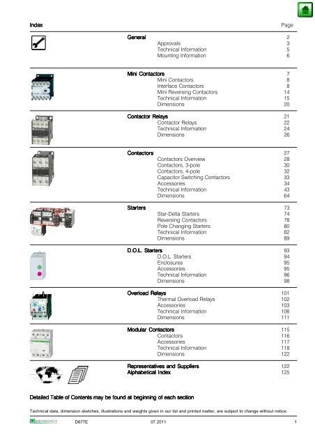
Index Page General 2 Approvals 3 Technical Information 5 Mounting ...
Index Page General 2 Approvals 3 Technical Information 5 Mounting ...
Index Page General 2 Approvals 3 Technical Information 5 Mounting ...

Create successful ePaper yourself
Turn your PDF publications into a flip-book with our unique Google optimized e-Paper software.
<strong>Index</strong> <strong>Index</strong><br />
<strong>Page</strong><br />
Detailed Detailed Detailed Table Table Table of of Contents Contents may may be be be found found at at at beginning beginning of of each each each section<br />
section<br />
<strong>General</strong> <strong>General</strong><br />
2<br />
<strong>Approvals</strong> 3<br />
<strong>Technical</strong> <strong>Information</strong> 5<br />
<strong>Mounting</strong> <strong>Information</strong> 6<br />
Mini Mini Contactors Contactors Contactors<br />
7<br />
Mini Contactors 8<br />
Interface Contactors 8<br />
Mini Reversing Contactors 14<br />
<strong>Technical</strong> <strong>Information</strong> 15<br />
Dimensions 20<br />
Contactor Contactor Relays Relays<br />
21<br />
Contactor Relays 22<br />
<strong>Technical</strong> <strong>Information</strong> 24<br />
Dimensions 26<br />
Contactors Contactors<br />
27<br />
Contactors Overview 28<br />
Contactors, 3-pole 30<br />
Contactors, 4-pole 32<br />
Capacitor Switching Contactors 33<br />
Accessories 34<br />
<strong>Technical</strong> <strong>Information</strong> 43<br />
Dimensions 64<br />
Starters Starters<br />
73<br />
Star-Delta Starters 74<br />
Reversing Contactors 78<br />
Pole Changing Starters 80<br />
<strong>Technical</strong> <strong>Information</strong> 82<br />
Dimensions 89<br />
D.O.L. D.O.L. Starters Starters<br />
93<br />
D.O.L. Starters 94<br />
Enclosures 95<br />
Accessories 95<br />
<strong>Technical</strong> <strong>Information</strong> 96<br />
Dimensions 98<br />
Overload Overload Relays Relays<br />
101<br />
Thermal Overload Relays 102<br />
Accessories 103<br />
<strong>Technical</strong> <strong>Information</strong> 106<br />
Dimensions 111<br />
Modular Modular Contactors Contactors<br />
115<br />
Contactors 116<br />
Accessories 117<br />
<strong>Technical</strong> <strong>Information</strong> 118<br />
Dimensions 122<br />
Representatives Representatives and and Suppliers Suppliers<br />
122<br />
Alphabetical Alphabetical <strong>Index</strong> <strong>Index</strong> <strong>Index</strong><br />
125<br />
<strong>Technical</strong> data, dimension sketches, illustrations and weights given in our list and printed matter, are subject to change without notice.<br />
D677E 07 2011<br />
1
<strong>General</strong><br />
<strong>General</strong><br />
Test Test Authorities, Authorities, Authorities, Registration Registration Mark, Mark, <strong>Approvals</strong> <strong>Approvals</strong><br />
<strong>Approvals</strong><br />
Low voltage switchgear from Benedict GmbH is built and tested<br />
to national and international specifications. All devices suit all<br />
important specifications without any test obligation, like VDE, BS<br />
and also relative to IEC Recommendations and to European Standards<br />
like IEC 947 and EN 60947.<br />
It is for this reason of our Low voltage switchgear is used all over the<br />
world. In order to provide special versions, limitations to the max.<br />
voltages, currents and power ratings or special markings are<br />
sometimes necessary.<br />
Quality Quality Control Control System<br />
System<br />
Since November 1991 Benedict GmbH has been certified according to<br />
the quality control system ÖNORM ÖNORM EN EN ISO ISO 29001 29001. 29001 The target of the ISOcertification<br />
is, to grant the customer the quality of the performance of<br />
his supplier, who is audited in accordance with this standard.<br />
Marking of auxiliary contacts<br />
At several devices in UL-data are two voltages for auxiliary contacts<br />
mentioned (e. g.: 600 volts at same potential, 150 volts at different<br />
potentials). That means, if the voltage is higher than 150 volts, the control<br />
voltage applied to input terminals must be at the same potential.<br />
Marking of Max. rated values per pole Contact<br />
auxiliary contacts Voltage Current Cont. Rating<br />
according to Make Break Current Code<br />
CSA and UL V A A A Designation<br />
Heavy Duty AC 120 60 6 10 A150<br />
(HD or HVY DTY) AC 240<br />
AC 480<br />
AC 600<br />
30<br />
15<br />
12<br />
3<br />
1,5<br />
1,2<br />
10<br />
10<br />
10<br />
A300<br />
A600<br />
A600<br />
DC 125<br />
DC 250<br />
2,2<br />
1,1<br />
2,2<br />
1,1<br />
10<br />
10<br />
N150<br />
N300<br />
DC 600 0,4 0,4 10 N600<br />
Standard Duty AC 120 30 3 5 B150<br />
(SD or STD DTY) AC 240<br />
AC 480<br />
AC 600<br />
15<br />
7,5<br />
6<br />
1,5<br />
0,75<br />
0,6<br />
5<br />
5<br />
5<br />
B300<br />
B600<br />
B600<br />
DC 125<br />
DC 250<br />
1,1<br />
0,55<br />
1,1<br />
0,55<br />
5<br />
5<br />
P150<br />
P300<br />
DC 600 0,2 0,2 5 P600<br />
- AC 120 15 1,5 2,5 C150<br />
AC 240<br />
AC 480<br />
AC 600<br />
7,5<br />
3,75<br />
3<br />
0,75<br />
0,375<br />
0,3<br />
2,5<br />
2,5<br />
2,5<br />
C300<br />
C600<br />
C600<br />
DC 125<br />
DC 250<br />
0,55<br />
0,27<br />
0,55<br />
0,27<br />
2,5<br />
2,5<br />
Q150<br />
Q300<br />
DC 600 0,1 0,1 2,5 Q600<br />
- AC 120 3,6 0,6 1 D150<br />
AC 240 1,8 0,3 1 D300<br />
DC 125 0,22 0,22 1 R150<br />
DC 250 0,11 0,11 1 R300<br />
- AC 120 1,8 0,3 0,5 E150<br />
CE-Marking<br />
The manufacturer has to sign his products with the CE-Marking. With the<br />
CE-Marking the manufacturer confirms the accordance with the different<br />
EEC Directives. The CE-Marking is absolutely necessary to sell the<br />
products in the EEC.<br />
Below you find the EEC Directives concerning our products.<br />
Low Voltage Directive 2006/95/EC<br />
EMC Directive 2004/108/EC<br />
RoHS + WEEE 2002/95/EC + "002/96/EC<br />
Country Country<br />
North North America America<br />
Switzerland Switzerland Russia Russia<br />
China China<br />
China<br />
State deputy or private examination UL SEV GOST CCC<br />
(state admitted) Canada, USA<br />
Label marking Listed<br />
of examination boards<br />
Component<br />
Duty of approvals all switchgear all switchgear all switchgear all switchgear<br />
Explanations Explanations for for for choice choice and and supply supply of of low low voltage voltage switchgear switchgear switchgear in in Canada Canada and and USA<br />
USA<br />
Low voltage switchgear for auxiliary circuits (e. g. contactor relays, control<br />
units, auxiliary contacts in general) usually approved for "Heavy Duty" or<br />
"Standard Duty" UL and besides these marked with the admissible max.<br />
voltage or with short codes (see table).<br />
Discernment at UL-Standards<br />
Recognized Recognized Component Component<br />
Listed<br />
Listed<br />
Industrial Industrial Control Control Equipment Equipment Industrial Industrial Control Control Equipment<br />
Equipment<br />
UL issues yellow "Guide cards" UL issues white "Guide cards"<br />
with Guide- and File-No. with Guide- and File-No.<br />
Devices have permission to be Devices have to be marked<br />
marked with with the<br />
on the label "UL-Listing Mark"<br />
Devices as components approved for Devices approved for "field wiring",<br />
"factory wiring":<br />
devices for employment in control<br />
panels, when they are selected, a) devices for employment<br />
mounted and wired according to in control panels, when<br />
the charging conditions by skilled they are mounted and<br />
worker. wired by skilled worker.<br />
b) devices for retail in USA<br />
Valid UL-Standards: Valid UL-Standards:<br />
UL 508 "Standard for Industrial UL 508 "Standard for Industrial Control<br />
Control Equipment" Equipment" (unlimited)<br />
(partly limited)<br />
Are devices approved as "Listed Equipment" the approval is also valid<br />
for using as "Recognized Component" .<br />
2 D677E
<strong>Approvals</strong><br />
<strong>Approvals</strong><br />
Country North America Switzerland Europe Russia China CENELEC<br />
GOST CB-Certificates<br />
UL SEV<br />
Type<br />
Mini Contactors, Reversing Contactors K1 and Accessories<br />
K1-07D..(=) o - o o o - o<br />
K1-07L..(=) - o o o o - o<br />
K1-07F..(=) - o - o - - -<br />
K1-09D..(=) o - o o o x o<br />
K1-09L..(=) - o o o o x o<br />
K1-09F..(=) - o - o - x -<br />
K1-12D..(=) o - - o - - -<br />
K1W09D01(=) o - - o - x -<br />
K1W12D01(=) o - - o - - -<br />
K1W09L01(=) - o - o - x -<br />
HK.., HKM.. o - o o - - o<br />
RC-K1 o - - o - - -<br />
Contactor Relays Series K3 and KG3<br />
K3-07A..(=) o - o o - - -<br />
K3-07D..(=) o - o o - - -<br />
KG3-07.. o - - o - - o<br />
Contactors Series K3<br />
K3-10A..(=) o - o o o o o<br />
K3-14A..(=) o - o o o o o<br />
K3-18A..(=) o - o o o o o<br />
K3-22A..(=) o - o o o o o<br />
K3-24A..(=) o - o o o o o<br />
K3-32A..(=) o - o o o o o<br />
K3-40A..(=) o - o o o o o<br />
K3-50A..(=) o - o o o o o<br />
K3-62A..(=) o - o o o o o<br />
K3-74A..(=) o - o o o o o<br />
K3-90A..(=) o - - o - o -<br />
K3-115A..(=) o - - o - o -<br />
K3-151A..(=) o - - o - - -<br />
K3-176A..(=) o - - o - - -<br />
K3-210A..(=) x - - o - - -<br />
K3-260A..(=) x - - o - - -<br />
K3-316A..(=) x - - o - - -<br />
K3-450A..(=) o - - o - - -<br />
K3-550A..(=) o - - o - - -<br />
K3-700A..(=) o - - o - - -<br />
K3-860A..(=) o - - o - - -<br />
K3-1000A..(=) - - - o - - -<br />
K3-1200A..(=) o - - o - - -<br />
Contactors DC-operated Series KG3<br />
KG3-10.., -14.. o - - o - - o<br />
KG3-18.., -22.. o - - o - - o<br />
KG3-24.., -32.. o - - o - - o<br />
KG3-40.. o - - o - - o<br />
Capacitor Contactors Series K3<br />
K3-18K.. o - - o o o o<br />
K3-24K.. o - - o o o o<br />
K3-32K.. o - - o o o o<br />
K3-50K.. o - - o o o o<br />
K3-62K.. o - - o o o o<br />
K3-74K.. o - - o o o o<br />
K3-90K.. o - - o - o -<br />
K3-115K.. o - - o - o -<br />
Aux. contacts<br />
HN.., HTN.. o - o o o o o<br />
HA.. o - o o o - o<br />
HB.. o - o o o o o<br />
K2-DK, K2-SK o - - o - - -<br />
HKA.., HKT.. o - - o - - -<br />
HKF22 - - - o - - -<br />
o In standard version approved x In test - Not provided for test till now<br />
D677E 3
<strong>Approvals</strong><br />
<strong>Approvals</strong><br />
Country North America Switzerland Europe Russia China CENELEC<br />
GOST CB-Certificates<br />
UL SEV<br />
Type<br />
Accessories<br />
K2-T..E, -A - - - o - - -<br />
K2-TP o - - o - - -<br />
K2-L o - - o - - -<br />
K2-IN. o - - o - - -<br />
K2-UN. o - - o - - -<br />
K2-IM - - - o - - -<br />
K2-E o - - o - - -<br />
VG-K2 - - - o - - -<br />
RC-K3 o - - o - - -<br />
Reversing Contactors , Serie KW3<br />
KW3-10 o - - o - - -<br />
KW3-14 o - - o - - -<br />
KW3-18 o - - o - - -<br />
KW3-22 o - - o - - -<br />
KW3-24 o - - o - - -<br />
KW3-32 o - - o - - -<br />
KW3-40 o - - o - - -<br />
D.O.L. Starters<br />
P1.. o - - o - - -<br />
Thermal Overload Relays<br />
U3/32 o - o o o - o<br />
U3/42 o - o o o - o<br />
U3/74 o - o o o - o<br />
U12/16E o - o o o - o<br />
U12/16A - - o o o - o<br />
U12/16EM - - o o o - o<br />
U12/16EQ - - o o o - o<br />
U32 o - - o o - o<br />
U60 o - - o o - o<br />
U85 o - o o o - o<br />
U180 x - - o - - -<br />
U320 x - - o - - -<br />
U840 - - - o - - -<br />
U1250 - - - o - - -<br />
Modular Contactors<br />
R20 o - o o o - o<br />
R25 o - o o o - o<br />
R40 o - o o o - o<br />
R63 o - o o o - o<br />
K1R - - - o o - o<br />
RH11 o - - o o - o<br />
o In standard version approved x In test - Not provided for test till now<br />
- - - and and - - - Guide- Guide- Guide- and and File-No. File-No.<br />
File-No.<br />
These data are important for UL-inspecting engineers.<br />
Devices Guide-No. File-No.<br />
Kanada USA Kanada USA<br />
Contactors NLDX7 NLDX NLDX8 NLDX2 E41502<br />
Reversing Contactors NLDX7 NLDX - - E41502<br />
Control Relays, Accessories NKCR7 NKCR NKCR8 NKCR2 E66273<br />
Thermal Overload Relays NKCR7 NKCR - - E66273<br />
Cam Switches NLRV7 NLRV - -<br />
Circuit Breakers as Manual Motor Controller NLRV7 NLRV - - E129916<br />
Circuit Breakers as Combination Motor Controller NKJH7 NKJH - - E197641<br />
Bus Bar Assemblies NLRV7 NLRV - - E129916<br />
Accessories NKCR7 NKCR - - E66273<br />
4 D677E
<strong>Technical</strong> <strong>Technical</strong> <strong>Information</strong><br />
<strong>Information</strong><br />
Degree Degree of of of protection protection acc. acc. to to IEC IEC 60947-1 60947-1<br />
60947-1<br />
Protection ratings are prefixed by the internationally agreed letters IP<br />
followed by two digits.<br />
1 st digit: Pertains to solid objects<br />
2 nd digit: Pertains to water.<br />
1 st Short description Definition<br />
digit<br />
1 Protected against Excludes solid objects exceeding 50 mm<br />
solid objects in diameter and protects against contact<br />
greater than 50 mm with live and moving parts by a large body<br />
surface such as a hand (but not against<br />
deliberate access).<br />
2L Protected against Excludes solid objects exceeding<br />
solid objects 12,5 mm in diameter and protects against<br />
greater than contact with live and moving parts by a<br />
12,5 mm and standard test finger or similar objects<br />
against contact by not exceeding 80 mm in length.<br />
standard test finger<br />
3 Protected against Excludes solid objects exceeding 2,5 mm<br />
solid objects in diameter or thickness.<br />
greater than 2,5mm<br />
4 Protected against Excludes solid objects exceeding 1 mm<br />
solid objects in diameter or thickness.<br />
greater than 1 mm<br />
5 Dust protected Prevents ingress of dust in quantities<br />
and locations that would interfere with<br />
the intended operation of the equipment.<br />
6 Dust tight Prevents ingress of dust.<br />
Terminal Terminal Terminal markings markings acc. acc. to to EN50011 EN50011<br />
EN50011<br />
Auxiliary contacts of AC contactors and contacts of contactor relays and<br />
thermal overload relays are particularly marked. The terminal markings of<br />
normally-open contacts are printed as positive figures, they of normallyclosed<br />
contacts as negative figures.<br />
This gives a clear indication of the function of the contacts.<br />
The figure below illustrates the determination of terminal markings for<br />
contactors with auxiliary contact blocks.<br />
Sequence number<br />
Function number<br />
The complete terminal marking according to EN<br />
50011 and EN 50012 results from the sequence<br />
numbers on the contactor relay or ac contactor<br />
(2., 3.) and the function numbers on the auxiliary<br />
contact blocks (e. g. .1, .2, or .3, .4).<br />
2 nd Short description Definition<br />
digit<br />
1 Protected against Dripping water (vertically falling drops)<br />
dripping water shall have no harmful effect.<br />
2 Protected against Vertically dripping water shall have no<br />
dripping water harmful effect when the enclosure is tilted<br />
when tilted at any angle up to 15° from its normal<br />
up to 15° position.<br />
3 Protected against Water falling as a spray at an angle up<br />
spraying water to 60° from the vertical shall have no<br />
harmful effect.<br />
4 Protected against Water splashed against the enclosure<br />
splashing water from any direction shall have no harmful<br />
effect.<br />
5 Protected against Water protected by a nozzle against the<br />
water jets enclosure from any direction shall have<br />
no harmful effect.<br />
6 Protected against Water from heavy seas or water<br />
heavy seas projected in powerful jets shall not<br />
enter the enclosure in harmful<br />
quanties.<br />
7 Protected against Ingress of water in a harmful quantity<br />
the effects of shall not be possible when the<br />
immersion enclosure is immersed in water under<br />
standard conditions of pressure and<br />
time.<br />
8 Protected against No ingress of water.<br />
submersion<br />
Resistance Resistance to to climatic climatic conditions conditions acc. acc. to to IEC60068 IEC60068<br />
IEC60068<br />
Open-type devices are climate-resistant in the constant climate according<br />
to IEC60068-2-3 (this is a climate with an ambient temperature of 40°C and<br />
an atmospheric humidity of 90 to 95%).<br />
Enclosed devices are climate-resistant in an alternating climate according<br />
to IEC 68-2-30 (this is a moist alternating climate with a 24-hour cycle<br />
between climates with an ambient temperature of 25°C, and an atmospheric<br />
humidity of 95 to 100% and an ambient temperature of 40°C, and an<br />
atmospheric humidity of 90 to 96% in the presence of condensation during<br />
rises in temperature).<br />
Data are valid up to an altitude of 2000m above sea level.<br />
Short Short circuit circuit protection<br />
protection<br />
Back up fuses should be used to protect contactors and starters against<br />
short circuits. For starters the device with the smaller admissible fuse at<br />
the main and at the control circuit (contactor or thermal overload) determines<br />
the fuse size.<br />
After a short circuit devices have to be checked for correct operation.<br />
Disconnect power before proceeding with any work on the equipment!<br />
D677E 5
<strong>Technical</strong> <strong>Technical</strong> <strong>Information</strong><br />
<strong>Information</strong><br />
<strong>Mounting</strong> <strong>Mounting</strong> positions positions of of contactors<br />
contactors<br />
K1-.. K(G)3-07 to K3-115, R.. K3-151.. to K3-1200..<br />
Terminal Terminal screws<br />
screws<br />
Devices Kind of connection<br />
Screw with Screw with Screw Screw driver Tightening torque<br />
Type washer clamp box w. nut Nm lb. inch<br />
Mini Contactors, , all conductors<br />
K1-.. M3,5 - - - Pz2 0,8 - 1,4 7 - 12<br />
Contactor Relays, , all conductors<br />
K(G)3-07.. M3,5 - - - Pz2 0,8 - 1,4 7 - 12<br />
Contactors<br />
Contactors<br />
Main conductor<br />
K(G)3-10.. to K3-22.. M3,5 - - - Pz2 0,8 - 1,4 7 - 12<br />
K(G)3-24.. to K3-40.. - M5 - - Pz2 2,5 - 3 22 - 26<br />
K3-50.. to K3-74.. - M6 - - Pz3 3,5 - 4,5 31 - 40<br />
K3-90, K3-115 - - M8 - 4mm hex socket 4 - 6,5 35 - 57<br />
K3-116.. to K3-176.. - - - M8 17 150<br />
K3-210.. to K3-316.. - - - M10 35 315<br />
K3-450.. to K3-700.. - - - M12 60 540<br />
K3-860.. - - - M14 75 675<br />
K3-1000.., K3-1200.. - - - M12 60 540<br />
Auxiliary conductor<br />
K(G)3-10 to K3-22<br />
Coil conductor<br />
M3,5 - - - Pz2 0,8 - 1,4 7 - 12<br />
K(G)3-10 to K3-1200 M3,5 - - - Pz2 0,8 - 1,4 7 - 12<br />
Accessories<br />
Accessories<br />
HK, HKM M3,5 - - - Pz2 0,8 - 1,4 7 - 12<br />
HA, HN, K2-.., HB.. M3,5 - - - Pz2 0,8 - 1,4 7 - 12<br />
Thermal Thermal Thermal Overload Overload Relays<br />
Relays<br />
Main conductor<br />
U12/16 M4 - - - Pz2 1,2 - 1,8 11 - 16<br />
U3/32 M3,5 - - - Pz2 0,8 - 1,4 7 - 12<br />
U3/42 M5 - - - Pz2 2,5 - 3 22 - 26<br />
U3/74 - M6 - - Pz3 3,5 - 4,5 31 - 40<br />
UAT21 - M4 - - Size 3, 4 1,2 - 1,8 11 - 16<br />
UAT22 - M4 - - Size 3, 4 1,2 - 1,8 11 - 16<br />
UAT23 - M5 - - Size 3, 4, 5 2,5 - 3 22 - 26<br />
Auxiliary conductor<br />
All devices M3,5 - - - Pz2 0,8 - 1,4 7 - 12<br />
Contactors Contactors for for Distribution Distribution Boards<br />
Boards<br />
Conductors<br />
R20, R25 - M3,5 - - Pz1 0,8 - 1,4 7 - 12<br />
R40, R63 - M5 - - Pz2 2,5 - 3 22 - 26<br />
K1R<br />
Coil conductor<br />
M3,5 - - - Pz2 0,8 - 1,4 7 - 12<br />
R20, R25 - M3 - - Pz1 0,6 - 1,2 5 - 11<br />
R40, R63 - M3 - - Pz2 0,6 - 1,2 5 - 11<br />
K1R M3,5 - - - Pz2 0,8 - 1,4 7 - 12<br />
6 D677E
Mini Mini Mini Contactors<br />
Contactors<br />
Mini Contactor Relays 4-pole 8<br />
Auxiliary Contact Blocks<br />
Interface Contactor Relays<br />
Mini Contactors 10<br />
Auxiliary Contact Blocks<br />
Mini Contactors With Fast On Tab Connectors 12<br />
Mini Contactors With Solder Pins 12<br />
Coil voltages 12<br />
Mini Reversing Contactors 14<br />
Auxiliary Contact Blocks<br />
<strong>Technical</strong> Data 16<br />
Dimensions 20<br />
D677E 7
Mini Mini Contactor Contactor Contactor Relays Relays 4-pole 4-pole<br />
AC Operated<br />
Ratings Ratings Therm. Contacts 2) Type Type<br />
Coil voltage 1)<br />
Distinc. Additional 24 24 24V 50/60Hz<br />
Number Contact 230 230 220-230V 50Hz<br />
24VS 24VS 24V 50/60Hz w. protection 3)<br />
230VS 230VS 220-230V 50Hz w. protection 3)<br />
AC15 AC15<br />
Rated 24VM 24VM 24VM 24V 50/60Hz 24V= DC<br />
Current 230VM 230VM 220-240V 50/60Hz 220V= DC<br />
230V 230V<br />
A<br />
400V<br />
A<br />
Ith A NO NC<br />
acc. to<br />
EN50011<br />
Blocks<br />
Type<br />
⏐<br />
�<br />
Pack Weight<br />
pcs. kg/pc.<br />
4-pole, 4-pole, With With Screw Screw Terminals<br />
Terminals<br />
3 2 10 4 - 40E 1 HK.. K1-07D40 K1-07D40 . . . . .<br />
. 10 0,16<br />
3 2 10 3 1 31E 1 HK.. K1-07D31 K1-07D31 . . . . .<br />
. 10 0,16<br />
3 2 10 2 2 22E 1 HK.. K1-07D22 K1-07D22 . . . . .<br />
. 10 0,16<br />
Auxiliary Auxiliary Contact Contact Contact Blocks Blocks For Contactor Relays<br />
Ratings Ratings Thermal Contacts 2) Type<br />
Type<br />
AC15 AC15<br />
Rated<br />
230V 230V 400V Current Pack Weight<br />
A A A NO NC pcs. kg/pc.<br />
3 2 10 1 1 HK11 HK11<br />
10 0,04<br />
3 2 10 - 2 HK02 HK02<br />
10 0,04<br />
3 2 10 2 - HK20 HK20<br />
10 0,04<br />
3 2 10 4 - HK40 HK40<br />
10 0,04<br />
3 2 10 2 2 HK22 HK22<br />
10 0,04<br />
3 2 10 - 4 HK04 HK04<br />
10 0,04<br />
Aux. Contact Blocks HK11 HK02 HK20 HK40 HK22 HK04<br />
Wiring Diagrams<br />
Distinc. Number according to EN50011<br />
for Contactor Relay with Auxiliary Contact Block<br />
K1-07D40 51E 51E<br />
42E 42E<br />
60E 60E<br />
80E 80E 80E<br />
62E 62E<br />
44E<br />
44E<br />
K1-07D31 42Y 33Y 51Y 71Y 53Y 35Y<br />
K1-07D22 33Y 24Y 42Y 62Y 44Y 26Y<br />
Preferable combinations with distinctive letter "E" according to DIN EN 50011<br />
1) Other coil voltages see page 12<br />
2) Contacts suitable for electronic circuits, according to EN947-5-4 for rated voltage 24V DC<br />
(test ratings 17V DC, 5mA) Positively guided contacts<br />
3) with built-in coil suppressor (varistor)<br />
8 D677E
DC Solenoid Operated<br />
Type Type Coil voltage 1) Contacts 2) Additional<br />
24 24 24V= DC Distinc. Contact<br />
24VS 24VS 24V= DC with Number Blocks<br />
⏐ protection 2) � NO NC<br />
acc. to<br />
EN50011 Type<br />
Pack<br />
pcs.<br />
Weight<br />
kg/pc. Wiring Diagrams<br />
4-pole, 4-pole, With With Screw Screw Terminals, Terminals, Terminals, Coil Coil 2,5W<br />
2,5W<br />
K1-07D40= K1-07D40= K1-07D40= ... ...<br />
4 - 40E 1 HK.. 10 0,19<br />
K1-07D31= K1-07D31= K1-07D31= ... ...<br />
3 1 31E 1 HK.. 10 0,19<br />
K1-07D22= K1-07D22= K1-07D22= ... ...<br />
2 2 22E 1 HK.. 10 0,19<br />
4-pole, 4-pole, With With Screw Screw Terminals, Terminals, Coil Coil 1,5W, 1,5W, 19 19 to to 30V 30V DC DC<br />
DC with suppressor 3)<br />
K1-07D40= K1-07D40= 24VR 24VR<br />
4 - - 10 0,20<br />
K1-07D31= K1-07D31= K1-07D31= 24VR 24VR<br />
3 1 - 10 0,20<br />
K1-07D22= K1-07D22= 24VR 24VR<br />
2 2 - 10 0,20<br />
1) Other coil voltages on request<br />
2) Contacts suitable for electronic circuits, according to EN947-5-4 for rated voltage 24V DC<br />
(test ratings 17V DC, 5mA) Positively guided contacts<br />
3) with integrated coil suppressor (Transient Voltage Suppressor Diode)<br />
D677E 9
Mini Contactors AC Operated<br />
Power Ratings Rated Aux. Contacts 2) Type Coil voltage 1)<br />
Current Built-in Additional 24 24V 50/60Hz<br />
230 220-230V 50Hz<br />
24VS 24V 50/60Hz w. protection 3)<br />
AC2, AC3 AC1 230VS 220-230V 50Hz w. protection 3)<br />
380V 24VM 24V 50/60Hz 24V= DC<br />
400V 660V 230VM220-240V 50/60Hz 220V= DC<br />
415V 690V 690V ⏐ Pack Weight<br />
kW kW A NO NC Type ▼ pcs. kg/pc.<br />
3-pole, With Screw Terminals<br />
4 4 20 1 - 1 HKM.. K1-09D10 . . . 10 0,16<br />
5,5 5,5 20 1 - 1 HKM.. K1-12D10 . . . 10 0,16<br />
4 4 20 - 1 1HK.. K1-09D01 . . . 10 0,16<br />
5,5 5,5 20 - 1 1HK.. K1-12D01 . . . 10 0,16<br />
4-pole, With Screw Terminals<br />
4 4 20 - - 1HK.. K1-09D00-40 . . . 10 0,16<br />
5,5 5,5 20 - - 1HK.. K1-12D00-40 . . . 10 0,16<br />
Auxiliary Contact Blocks for Contactors K1-..<br />
Ratings Thermal Contacts 2) Type<br />
AC15 Rated<br />
230V 400V Current Pack Weight<br />
A A A NO NC pcs. kg/pc.<br />
3 2 10 1 1 HKM11 10 0,04<br />
3 2 10 - 2 HKM02 10 0,04<br />
3 2 10 2 2 HKM22 10 0,04<br />
Aux. Contact Blocks HKM11 HKM02 HKM22 HK11 HK02 HK40 HK22<br />
Wiring Diagrams<br />
Contactors with Auxiliary Contact Block<br />
Contacts according to EN50012<br />
K1-..D10 21 12 32 - - - -<br />
Contacts according to DIN EN50005<br />
K1-..D01 - - - 12 03 41 23<br />
K1-..D00-40 - - - 11 02 40 22<br />
Prefer combinations according to EN50012<br />
Suppressor Units for Contactors K1-..<br />
Voltage Range Type Pack Weight<br />
V pcs. kg/pc.<br />
12 - 48V AC/DC 1600nF / 22 Ohm RC-K1 24 10 0,01<br />
48 - 127V AC/DC 680nF / 270 Ohm RC-K1 110 10 0,01<br />
110 - 250V AC/DC 220nF / 2200 Ohm RC-K1 230 10 0,01<br />
1) Other coil voltages see page 12<br />
2) Contacts suitable for electronic circuits, according to EN947-5-4 for rated voltage 24V DC<br />
(test ratings 17V DC, 5mA) Positively guided contacts<br />
3) with built-in coil suppressor (varistor)<br />
10 D677E
DC Solenoid Operated<br />
Type<br />
Coil voltage 1) Aux. Contacts 2) Additional<br />
24 24V= DC Built Additional Overload<br />
24VS 24V= DC with in Relay<br />
⏐ protection 3) see<br />
⏐ page102 Pack Weight<br />
▼ NO NC Type pcs. kg/pc. Wiring Diagrams<br />
3-pole, With Screw Terminals, Coil 2,5W<br />
K1-09D10= . . . 1 - 1 HKM.. U12/16..K1 10 0,19<br />
K1-12D10= . . . 1 - 1 HKM.. U12/16..K1 10 0,19<br />
K1-09D01= . . . - 1 1 HK.. U12/16..K1 10 0,19<br />
K1-12D01= . . . - 1 1 HK.. U12/16..K1 10 0,19<br />
4-pole, With Screw Terminals, Coil 2,5W<br />
K1-09D00-40= . . . - - - U12/16..K1 10 0,19<br />
K1-12D00-40= . . . - - - U12/16..K1 10 0,19<br />
3-pole, With Screw Terminals, Coil 1,5W, 19 to 30V DC with suppressor 3)<br />
K1-09D10=24VR 1 - - U12/16..K1 10 0,20<br />
K1-09D01= 24VR - - 1 - U12/16..K1 10 0,20<br />
1) Other coil voltages on request<br />
2) Contacts suitable for electronic circuits, according to EN947-5-4 for rated voltage 24V DC<br />
(test ratings 17V DC, 5mA) Positively guided contacts<br />
3) with integrated coil suppressor (Transient Voltage Suppressor Diode)<br />
D677E 11
Mini Contactors AC Operated<br />
Power Ratings Rated Aux. Contacts 2) Type Coil voltage 1)<br />
Current Built Additional 24 24V 50/60Hz<br />
in 230 220-230V 50Hz<br />
24VS 24V 50/60Hz w. protection 2)<br />
AC2, AC3 AC1 230VS 220-230V 50Hz w. protection 2)<br />
380V 24VM 24V 50/60Hz 24V DC<br />
400V 660V 230VM220-240V 50/60Hz 220V DC<br />
415V 690V 690V ⏐ Pack Weight<br />
kW kW A NO NC Type ▼ pcs. kg/pc.<br />
3-pole, with Fast On Tab Connectors 1 x 6,3mm or 2 x 2,8mm<br />
4 4 16 1 - 1 HKM.. K1-09F10 . . . 10 0,16<br />
4 4 16 - 1 1 HK.. K1-09F01 . . . 10 0,16<br />
3-pole, with Solder Pins Ø1,15 for Printed Circuit Applications<br />
4 4 16 1 - - K1-09L10 . . . 10 0,16<br />
4 4 16 - 1 - K1-09L01 . . . 10 0,16<br />
4-pole, with Solder Pins Ø1,15 for Printed Circuit Applications<br />
Coil voltages for AC operated contactors<br />
4 4 16 - - - K1-09L00-40 . . . 10 0,16<br />
Suffix Voltage Marking Rated Control Voltage U s<br />
to<br />
contactor at the coil range<br />
type for for for 50Hz for 60Hz<br />
e.g. 50Hz 60Hz min. max. min. max.<br />
K1-09D10 24 V V V V V V<br />
12 12 12 11 12 12 12<br />
24 24 24 22 24 24 24<br />
42 42 42 38,5 42 42 42<br />
48 48 48 48 50 48 52<br />
90 100 100 90 100 100 105<br />
95 95-100 105-110 95 100 105 110<br />
100 100 110-115 100 105 110 115<br />
105 105-110 115-120 105 110 115 120<br />
110 110-115 120-125 110 115 120 125<br />
180 200 200 185 200 200 210<br />
1) Other coil voltages see page 12<br />
2) Contacts suitable for electronic circuits, according to EN947-5-4 for rated voltage 24V DC<br />
(test ratings 17V DC, 5mA) Positively guided contacts<br />
3) with built-in coil suppressor (varistor)<br />
Suffix Voltage Marking Rated Control Voltage U s<br />
to<br />
contactor at the coil range<br />
type for for for 50Hz for 60Hz<br />
e.g. 50Hz 60Hz min. max. min. max.<br />
K1-09D10 230 V V V V V V<br />
200 200 200-220 195 205 200 220<br />
210 205-215 220-230 205 215 220 230<br />
220 210-220 220-240 210 220 220 240<br />
230 220-230 230-250 220 230 230 250<br />
240 230-240 230 240 250 260<br />
400 380-400 400-440 380 400 400 440<br />
500 475-500 520-545 475 500 520 545<br />
550 525-550 600 525 550 570 600<br />
Standard voltages in bold type letters<br />
Operating range of magnet-coils: 0,85 x U s (min. value of rated<br />
control voltage) up to 1,1 x U s (max. value of rated control voltage)<br />
Coil not exchangeable<br />
12 D677E
DC Solenoid Operated<br />
Type<br />
Coil voltage 1) Aux. Contacts 2) Additional<br />
24 24V= DC Built Additional Overload<br />
24VS 24V= DC with in Relay<br />
⏐ protection 3) see<br />
⏐ page102 Pack Weight<br />
▼ NO NC Type pcs. kg/pc. Wiring Diagrams<br />
3-pole, with Fast On Tab Connectors 1 x 6,3mm or 2 x 2,8mm<br />
K1-09F10= . . . 1 - 1 HKM.. U12/16..K1 10 0,19<br />
K1-09F01= . . . - 1 1 HK.. U12/16..K1 10 0,19<br />
3-pole, with Solder Pins Ø1,15 for Printed Circuit Applications<br />
K1-09L10= . . . 1 - - - 10 0,19<br />
K1-09L01= . . . - 1 - - 10 0,19<br />
4-pole, with Solder Pins Ø1,15 for Printed Circuit Applications<br />
K1-09L00-40= . . . - - - - 10 0,19<br />
1) Other coil voltages on request<br />
2) Contacts suitable for electronic circuits, according to EN947-5-4 for rated voltage 24V DC<br />
(test ratings 17V DC, 5mA) Positively guided contacts<br />
3) with integrated coil suppressor (Transient Voltage Suppressor Diode)<br />
D677E 13
Mini Reversing Contactors, Mechanical Interlocked AC Operated<br />
Power Ratings Rated Aux. Contacts 2) Type Coil voltage 1)<br />
Current Built-in Additional 24 24V 50/60Hz<br />
on left on right 230 220-230V 50Hz<br />
hand side hand side 24VS 24V 50/60Hz w. protection 3)<br />
AC2, AC3 AC1 Contactor Contactor 230VS 220-230V 50Hz w. prot. 3)<br />
380V 24VM 24V 50/60Hz 24V DC<br />
400V 660V 230VM 220-240V 50/60Hz 220V DC<br />
415V 690V 690V K1 K2 ⏐ Pack Weight<br />
kW kW A NO NC Type Type ▼ pcs. kg/pc.<br />
3-pole, with Screw Terminals<br />
4 4 20 - 1 HKM11V HKM11X K1W09D01MC . . . 1 0,32<br />
5,5 5,5 20 - 1 HKM11V HKM11X K1W12D01MC . . . 1 0,32<br />
4 4 20 1 - - HKM.. K1W09D10MC . . . 1 0,32<br />
5,5 5,5 20 1 - - HKM.. K1W12D10MC . . . 1 0,32<br />
4-pole, with Screw Terminals<br />
4 4 20 - - - HKM.. K1W09D00-40MC . . 1 0,32<br />
5,5 5,5 20 - - - HKM.. K1W12D00-40MC . . 1 0,32<br />
3-pole, with Solder Pins Ø1,15 for Printed Circuit Applications<br />
4 4 16 - 1 - - K1W09L01MC . . . 1 0,32<br />
4 4 16 1 - - - K1W09L10MC . . . 1 0,32<br />
Auxiliary Contact Blocks for Mini Reversing Contactors K1-..<br />
Ratings Thermal Contacts 2) Type<br />
AC15 Rated<br />
230V 400V Current Pack Weight<br />
A A A NO NC pcs. kg/pc.<br />
3 2 10 1 1 HKM11V 10 0,04<br />
3 2 10 1 1 HKM11X 10 0,04<br />
Aux. Contact BlocksAux. Contact Blocks HKM11V HKM11X<br />
Wiring Diagrams<br />
Reversing Starter Connector<br />
For Reversing Starter Types, incl. Coil Connector Type Pack Weight<br />
pcs. kg/pc.<br />
K1W09D..MC, K1W12D..MC K1W-VB 1 0,01<br />
1) Other coil voltages see page 12<br />
2) Contacts suitable for electronic circuits, according to EN947-5-4 for rated voltage 24V DC<br />
(test ratings 17V DC, 5mA) Positively guided contacts<br />
3) with built-in coil suppressor (varistor)<br />
14 D677E
DC Solenoid Operated<br />
Type<br />
Coil voltage 1) Additional<br />
24 24V= DC Overload<br />
24VS 24V= DC with Relay<br />
⏐ protection 2) see<br />
⏐ page102 Pack Weight<br />
▼ Type pcs. kg/pc. Wiring Diagrams<br />
3-pole, with Screw Terminals<br />
K1W09D01MC= . . . U12/16..K1 1 0,32<br />
K1W12D01MC= . . . U12/16..K1 1 0,32<br />
K1W09D10MC= . . . U12/16..K1 1 0,32<br />
K1W12D10MC= . . . U12/16..K1 1 0,32<br />
4-pole, with Screw Terminals<br />
K1W09D00-40MC= . . U12/16..K1 1 0,32<br />
K1W12D00-40MC= . . U12/16..K1 1 0,32<br />
3-pole, with Solder Pins Ø1,15 for Printed Circuits Applications<br />
K1W09L01MC= . . . - 1 0,32<br />
K1W09L10MC= . . . - 1 0,32<br />
1) Other coil voltages on request<br />
2) with integrated coil suppressor (Transient Voltage Suppressor Diode)<br />
D677E 15
Mini Mini Contactors<br />
Contactors<br />
Data Data according according according to to to IEC IEC 947-4-1, 947-4-1, VDE VDE 0660, 0660, EN EN 60947-4-1<br />
60947-4-1<br />
Main Main Contacts Contacts<br />
Type K1-09D.. K1-09D.. K1-09F.. K1-09F.. K1-09L.. K1-09L.. K1-12D..<br />
K1-12D..<br />
Rated Rated insulation insulation voltage voltage U U<br />
V AC 690 i 1) 690 1) 690 2) 690 1)<br />
Making Making capacity capacity I I<br />
at U = 690V AC A 165 165 165 165<br />
eff e<br />
Breaking Breaking capacity capacity I Ieff<br />
cosϕ = 0,65<br />
400V AC<br />
500V AC<br />
A<br />
A<br />
100<br />
90<br />
100<br />
90<br />
100<br />
90<br />
100<br />
90<br />
690V AC A 80 80 80 80<br />
Utilization Utilization category category AC1<br />
AC1<br />
Switching Switching of of resistive resistive load<br />
load<br />
Rated operational current I (=I ) at 40°C, open e th A 20 20<br />
16 16<br />
16 16<br />
20 20<br />
20<br />
Rated operational power of three-phase resistive loads 230V kW 7,9 6 6 7,9<br />
50-60Hz, cosϕ = 1 240V kW 8,3 6,5 6,5 8,3<br />
400V kW 13,8 11 11 13,8<br />
415V kW 14,3 11,5 11,5 14,3<br />
Rated operational current I e (=I the ) at 60°C, enclosed A 16 12 12 16<br />
Rated operational power of three-phase resistive loads 230V kW 6,3 4,5 4,5 6,3<br />
50-60Hz, cosϕ = 1 240V kW 6,7 5 5 6,7<br />
400V kW 11 8 8 11<br />
415V kW 11,5 8,5 8,5 11,5<br />
Minimum cross-section of conductor at load with I e (=I th ) mm² 2,5 2,5 - 2,5<br />
Utilization Utilization Utilization category category AC2 AC2 and and AC3<br />
AC3<br />
Switching Switching Switching of of three-phase three-phase motors<br />
motors<br />
Rated operational current Ie open and enclosed<br />
220V<br />
230V<br />
A<br />
A<br />
12<br />
11,5<br />
12<br />
11,5<br />
12<br />
11,5<br />
15<br />
14,5<br />
240V A 11 11 11 14<br />
380-400V 380-400V A 9 9 9 12<br />
12<br />
415-440V A 8 8 8 11<br />
500V A 7 7 7 9<br />
660-690V A 5 5 5 6,5<br />
Rated operational power of three-phase motors 220-240V kW 3 3 3 4<br />
50-60Hz 380-440V 380-440V kW kW<br />
4 4 4 5,5 5,5<br />
5,5<br />
500-690V kW 4 4 4 5,5<br />
Utilization Utilization category category AC4<br />
AC4<br />
Switching Switching of of of squirrel squirrel cage cage motors, motors, inching<br />
inching<br />
Rated operational current Ie open and enclosed<br />
220V<br />
230V<br />
A<br />
A<br />
12<br />
11,5<br />
12<br />
11,5<br />
12<br />
11,5<br />
15<br />
14,5<br />
240V A 11 11 11 14<br />
380-400V 380-400V A 9 9 9 12<br />
12<br />
415-440V A 8 8 8 11<br />
500V A 7 7 7 9<br />
660-690V A 5 5 5 6,5<br />
Rated operational power of three-phase motors 220-240V kW 3 3 3 4<br />
50-60Hz 380-440V 380-440V kW kW<br />
4 4 4 5,5<br />
5,5<br />
500-690V kW 4 4 4 5,5<br />
1) Suitable at 690V for: earthed-neutral systems, overvoltage category I to IV, pollution degree 3 (standard-industry): Uimp = 8kV.<br />
Data for other conditions on request.<br />
2) Suitable at 690V for pollution degree 2, Uimp = 6kV.<br />
Pollution degree 3 U i = 690V non-tracking of the printed circuit CTI ≥600<br />
Pollution degree 3 U i = 500V non-tracking of the printed circuit CTI ≥400<br />
Pollution degree 3 U i = 400V non-tracking of the printed circuit CTI ≥100<br />
16 D677E
Mini Mini Contactors<br />
Contactors<br />
Data Data according according to to IEC IEC 947-4-1, 947-4-1, VDE VDE 0660, 0660, EN EN EN 60947-4-1<br />
60947-4-1<br />
Main Main Contacts Contacts<br />
Type K1-09D.. K1-09D.. K1-09F.. K1-09F.. K1-09L.. K1-09L.. K1-09L.. K1-12D..<br />
K1-12D..<br />
Utilization Utilization category category DC1<br />
DC1<br />
Switching Switching of of resistive resistive load load<br />
1 pole 24V A 20 16 16 20<br />
Time constant L/R ≤1ms 60V A 20 16 16 20<br />
Rated operational current Ie 110V<br />
220V<br />
A<br />
A<br />
5<br />
0,6<br />
5<br />
0,6<br />
5<br />
0,6<br />
5<br />
0,6<br />
3 poles in series 24V A 20 20 20 20<br />
60V A 20 20 20 20<br />
110V A 20 20 20 20<br />
220V A 16 16 16 16<br />
Utilization Utilization category category DC3 DC3 and and and DC5<br />
DC5<br />
Switching Switching of of shunt shunt shunt motors motors<br />
1 pole 24V A 20 16 16 20<br />
and and series series motors motors<br />
60V A 5 5 5 5<br />
Time constant L/R ≤15ms 110V A 1 1 1 1<br />
Rated operational current Ie 220V A 0,15 0,15 0,15 0,15<br />
3 poles in series 24V A 20 16 16 20<br />
60V A 20 16 16 20<br />
110V A 20 16 16 20<br />
220V A 2 2 2 2<br />
Maximum Maximum ambient ambient temperature<br />
temperature<br />
Operation open °C -40 to +60 (+90) 1)<br />
enclosed °C -40 to +40<br />
with thermal overload relay open °C -25 to +60<br />
enclosed °C -25 to +40<br />
Storage °C -50 to +90<br />
Short Short Short circuit circuit circuit protection protection<br />
protection<br />
for contactors without thermal overload relay<br />
Coordination-type "1" according to IEC 947-4-1<br />
Contact welding without hazard of persons<br />
max. fuse size<br />
Coordination-type “2” according to IEC 947-4-1<br />
Light contact welding accepted<br />
gL (gG) A 40 40 40 40<br />
max. fuse size<br />
Contact welding not accepted<br />
gL (gG) A 25 25 25 25<br />
max. fuse size<br />
For contactors with thermal overload relay the<br />
device with the smaller admissible backup fuse<br />
gL (gG) A 10 10 10 10<br />
(contactor or thermal overload relay) determines the fuse size.<br />
Cable Cable Cable cross-sections<br />
cross-sections<br />
for contactors without thermal overload relay<br />
main connector solid or stranded mm² 0,5 - 2,5 Fast on Solder connector 0,5 - 2,5<br />
flexible mm² 0,5 - 2,5 1x 6,3 x 0,8 Ø 1,15 0,5 - 2,5<br />
flexible with multicore cable end mm² 0,5 - 1,5 or 0,5 - 1,5<br />
Cables per clamp 2 2x 2,8 x 0,8 - 2<br />
solid or stranded AWG 18 - 14 18 - 14<br />
Frequency Frequency of of operations operations operations z z<br />
without load 1/h 10000 10000 10000 10000<br />
Contactors without thermal overload relay AC3, Ie AC4, Ie DC3, Ie 1/h<br />
1/h<br />
1/h<br />
600<br />
120<br />
600<br />
600<br />
120<br />
600<br />
600<br />
120<br />
600<br />
700<br />
150<br />
700<br />
Mechanical Mechanical life life AC operated S x 106 5 5 5 5<br />
DC operated S x 106 15 15 15 15<br />
Short Short time time current current current<br />
10s-current A 96 96 96 120<br />
Power Power loss loss per pole at I /AC3 400V W 0,15 0,15 0,15 0,25<br />
e<br />
Resistance Resistance to to shock shock according according to to IEC IEC IEC 68-2-27<br />
68-2-27<br />
Shock time 20ms sine-wave<br />
AC operated NO g 5 5 5 5<br />
NC g 5 5 5 5<br />
DC operated NO g 8 8 8 8<br />
NC g 6 6 6 6<br />
1) With reduced control voltage range 0,9 up to 1,0 x U s and with reduced rated current I e /AC1according to I e /AC3<br />
D677E 17
Mini Mini Contactors<br />
Contactors<br />
Data Data according according according to to to IEC IEC IEC 947-5-1, 947-5-1, VDE VDE 0660, 0660, EN EN 60947-5-1 60947-5-1<br />
60947-5-1<br />
Auxiliary Auxiliary Contacts Contacts<br />
Type K1-07D.. K1-07D.. K1-07D..=<br />
K1-07D..=<br />
K1-09D.. K1-09D.. K1-09D..= K1-09D..= K1-07D..= K1-07D..= 24VR 24VR<br />
K1-07L..(=)<br />
K1-07L..(=)<br />
K1-12D.. K1-12D.. K1-12D..= K1-12D..= K1-09D..= K1-09D..= 24VR 24VR K1-09F..(=) K1-09F..(=) K1-09L..(=) K1-09L..(=) HK..<br />
HK..<br />
Rated Rated insulation insulation voltage voltage voltage U U<br />
V AC 690 i 1) 690 1) 690 1) 690 1) 690 2) 690 1)<br />
Thermal Thermal rated rated current current I I to 690V<br />
th th<br />
Ambient temperature 40°C A 10 10 10 10 10 10<br />
60°C A 6 6 6 6 6 6<br />
Power Power loss loss per pole at I W 0,5 0,5 0,5 0,5 0,5 0,5<br />
th<br />
Utilization Utilization category category AC15 AC15<br />
AC15<br />
Rated operational current Ie 220-240V<br />
380-415V<br />
A<br />
A<br />
3<br />
2<br />
3<br />
2<br />
3<br />
2<br />
3<br />
2<br />
3<br />
2<br />
3<br />
2<br />
440V A 1,6 1,6 1,6 1,6 1,6 1,6<br />
500V A 1,2 1,2 1,2 1,2 1,2 1,2<br />
660-690V A 0,6 0,6 0,6 0,6 0,6 0,6<br />
Utilization Utilization category category DC13 DC13<br />
DC13<br />
Rated operational current Ie 60V<br />
110V<br />
A<br />
A<br />
2<br />
0,4<br />
2<br />
0,4<br />
2<br />
0,4<br />
2<br />
0,4<br />
2<br />
0,4<br />
2<br />
0,4<br />
220V A 0,1 0,1 0,1 0,1 0,1 0,1<br />
Maximum Maximum ambient ambient temperature<br />
temperature<br />
Operation open °C -40 to +60 (+90) 3)<br />
enclosed °C -40 to +40<br />
Storage °C -40 to +90<br />
Short Short circuit circuit protection<br />
protection<br />
short-circuit current 1kA,<br />
contact welding not accepted<br />
max. fuse size gL (gG) A 20 20 20 20 20 20<br />
For contactors with thermal overload relay the<br />
device with the smaller admissible control fuse<br />
(contactor or thermal overload relay)<br />
determines the fuse size.<br />
Power Power Power consumption consumption consumption of of coils<br />
coils<br />
AC operated inrush VA 25 - - 25 25 -<br />
sealed VA 4 - 5 - - 4 - 5 4 - 5 -<br />
W 1,2 - - 1,2 1,2 -<br />
DC operated inrush W - 2,5 1,5 2,5 2,5 -<br />
sealed W - 2,5 1,5 2,5 2,5 -<br />
Operation Operation range range of of coils coils<br />
19 - 30V DC<br />
in multiples of control voltage Us 0,85 - 1,1 0,8 - 1,1 0,85 - 1,1 0,85 - 1,1 -<br />
Switching Switching time time time at control voltage U ±10% s<br />
4) 5)<br />
AC operated make time ms 15 - 25 - - 15 - 25 15 - 25 -<br />
release time ms 8 - 25 - - 8 - 25 8 - 25 -<br />
arc duration ms 10 -15 - - 10 -15 10 -15 -<br />
DC operated make time ms - 15 - 19 15 - 19 15 - 19 15 - 19 -<br />
release time ms - 8 - 25 8 - 25 8 - 25 8 - 25 -<br />
arc duration ms - 10 -15 10 -15 10 -15 10 -15 -<br />
Cable Cable cross-section<br />
cross-section<br />
all connectors solid mm2 0,5 - 2,5 0,5 - 2,5 0,5 - 2,5 Fast on Solder connector 0,5 - 2,5<br />
flexible mm2 0,5 - 2,5 0,5 - 2,5 0,5 - 2,5 1x 6,3 x 0,8 Ø 1,15 0,5 - 2,5<br />
flexible with multicore cable end mm2 0,5 - 1,5 0,5 - 1,5 0,5 - 1,5 or<br />
2x 2,8 x 0,8<br />
0,5 - 1,5<br />
Clamps per pole 2 2 2 - - 2<br />
solid or stranded AWG 18 - 14 18 - 14 18 - 14 18 - 14<br />
1) Suitable at 690V for: earthed-neutral systems, overvoltage category I to IV, pollution degree 3 (standard-industry): Uimp = 8kV.<br />
Data for other conditions on request.<br />
2) Suitable at 690V for pollution degree 2, Uimp = 6kV.<br />
Pollution degree 3 U i = 690V non-tracking of the printed circuit CTI ≥600<br />
Pollution degree 3 U i = 500V non-tracking of the printed circuit CTI ≥400<br />
Pollution degree 3 U i = 400V non-tracking of the printed circuit CTI ≥100<br />
3) With reduced control voltage range 0,9 up to 1,0 x U s and with reduced thermal rated current I th to I e /AC15<br />
4) Summary switching time = release time + arc duration<br />
5) Release time of NC make time of NO increase when suppressor units for voltage peak protection are used (Varistor, RC-units, Diode units).<br />
18 D677E
Mini Mini Mini Contactors Contactors for for North North North America America<br />
America<br />
Data Data according according to to UL508<br />
UL508<br />
Main Main Contacts Contacts (cULus) (cULus)<br />
Type K1-09D.. K1-09D.. K1-09F.. K1-09F.. K1-09L.. K1-09L.. K1-07D.. K1-07D.. K1-12D.. K1-12D.. HK..<br />
HK..<br />
K1W09D01 K1W09D01<br />
K1W12D01<br />
K1W12D01<br />
Rated operational current "<strong>General</strong> Use" A 15 15 20 10 20 10<br />
Rated operational power of three-phase motors 110-120V hp 1½ 1½ 1½ - 2 -<br />
at 60Hz (3ph) 200-208V hp 3 3 3 - 3 -<br />
220-240V hp 3 3 3 - 3 -<br />
440-480V hp 5 5 5 - 7½ -<br />
550-600V hp 7½ 7½ 7½ - 10 -<br />
Rated operational power of of AC motors 110-120V hp ½ ½ ½ - ¾ -<br />
at 60Hz (1ph) 200-208V hp 1 1 1 - 1½ -<br />
220-240V hp 1½ 1½ 1½ - 2 -<br />
Fuse / Short-circuit current A/kA 30/5 30/5 30/5 - 30/5 -<br />
Rated voltage V AC 600 600 600 1) 600 600 600<br />
Auxiliary Auxiliary Auxiliary Contacts Contacts (cULus) (cULus)<br />
heavy pilot duty AC A600 A600 A600 A600 A600 A600<br />
standard pilot duty DC Q600 Q600 Q600 Q600 Q600 Q600<br />
1) Pollution degree CTI - PWB U i<br />
2 ≥ 100 600V<br />
3 ≥ 400 480V<br />
3 100 - 400 240V<br />
D677E 19
Mini Mini Contactors<br />
Contactors<br />
Dimensions<br />
Dimensions<br />
AC AC and and DC DC DC operated<br />
operated<br />
with screw terminals with fast on terminals<br />
K1-07D.. K1-07D..<br />
K1-07F.. K1-07F..<br />
K1-07F..<br />
K1-09D.. K1-09D..<br />
K1-12D..<br />
K1-12D..<br />
K1-09F..<br />
K1-09F..<br />
AC AC and and DC DC operated operated<br />
Auxiliary Auxiliary Contact Contact Blocks<br />
Blocks<br />
with solder connections<br />
K1-07L.. K1-07L..<br />
HK..<br />
HK..<br />
K1-09L..<br />
K1-09L..<br />
Reversing Reversing Contactors<br />
Contactors<br />
K1W09D..MC K1W09D..MC<br />
K1W09L..MC<br />
K1W09L..MC<br />
K1W12D..MC<br />
K1W12D..MC<br />
K1W09D..MC K1W09D..MC + + + U12/16E U12/16E U12/16E K1 K1<br />
K1<br />
K1W12D..MC K1W12D..MC + + + U12/16E U12/16E U12/16E K1 K1<br />
K1<br />
20 D677E
Contactor Contactor Relays<br />
Relays<br />
Contactor Relays 4-pole, AC Operated 22<br />
Auxiliary Contact Blocks 1-pole 22<br />
Contactor Relays 4-pole, DC Operated 23<br />
<strong>Technical</strong> Data 24<br />
Dimensions 26<br />
D677E 21
Contactor Contactor Relays Relays<br />
AC Operated<br />
Auxiliary Auxiliary Contact Contact Blocks Blocks 3)<br />
Accessories Accessories see page 34 - 38<br />
Ratings Ratings<br />
Contacts Type Type<br />
Coil voltage 1)<br />
Therm. Built-in Distinc. Additional 24 24 24V 50/60Hz<br />
Rated Number Contact 110 110 110V 50Hz 110-120V 60Hz<br />
Current acc. to Blocks 230 230 220-240V 50Hz 230-264V 60Hz<br />
AC15 AC15<br />
400 400 400 380-415V 50Hz 400-440V 60Hz<br />
230V 230V<br />
A<br />
400V<br />
A<br />
Ith A NO NC EN50011 Type<br />
⏐<br />
�<br />
Pack Weight<br />
pcs. kg/pc.<br />
4-pole, 4-pole, for for high high high switching switching capacity<br />
capacity<br />
12 12 4 20 4 - 40E max. 4 K3-07A40 K3-07A40 . . . . .<br />
. 1 0,22<br />
12 12 4 20 3 1 31E HN.. K3-07A31 K3-07A31 . . . . .<br />
. 1 0,22<br />
12 12 4 20 2 2 22E or K3-07A22 K3-07A22 . . . . .<br />
. 1 0,22<br />
12 12 4 20 - 4 04E HA.. K3-07A04 K3-07A04 . . . . .<br />
. 1 0,22<br />
4-pole, 4-pole, contacts contacts contacts suitable suitable for for electronic electronic circuits circuits according according to to to EN947-5-4 EN947-5-4 2)<br />
4 2 10 4 - 40E max. 4 K3-07D40 K3-07D40 . . . . .<br />
. 1 0,22<br />
4 2 10 3 1 31E HN.. K3-07D31 K3-07D31 . . . . .<br />
. 1 0,22<br />
4 2 10 2 2 22E K3-07D22 K3-07D22 . . . . .<br />
. 1 0,22<br />
4 2 10 - 4 04E K3-07D04 K3-07D04 . . . . .<br />
. 1 0,22<br />
Ratings RatingsThermal Ratings Contacts 2) Type Type<br />
Type<br />
AC15 AC15<br />
Rated<br />
230V 230V 230V 400V Current Pack Weight<br />
A A A NO NC EM LB pcs. kg/pc.<br />
1-pole, 1-pole, contacts contacts contacts suitable suitable for for electronic electronic circuits circuits according according to to to EN947-5-4 EN947-5-4 2)<br />
3 2 10 1 - - - HN10 HN10 HN10<br />
10 0,02<br />
3 2 10 - 1 - - HN01 HN01 HN01<br />
10 0,02<br />
3 2 10 - - 1 - HN10U HN10U<br />
10 0,02<br />
3 2 10 - - - 1 HN01U HN01U<br />
10 0,02<br />
1-pole, 1-pole, for for high high high switching switching capacity<br />
capacity<br />
6 3 25 1 - - - HA10 HA10<br />
10 0,03<br />
6 3 25 - 1 - - HA01 HA01<br />
10 0,03<br />
1) Other coil voltages see page 40<br />
2) Contacts suitable for electronic circuits, according to EN947-5-4 for rated voltage 24V DC<br />
(test ratings 17V DC, 5mA) Positively guided contacts<br />
3) <strong>Technical</strong> Data see page 62<br />
22 D677E
DC Operated<br />
Type Type Coil voltage 1) Contacts<br />
24 24 24V DC Built-in Distinc. Additional<br />
60 60 60V DC Number Contact<br />
110 110 110V DC acc. to Blocks<br />
220 220 220V DC<br />
⏐<br />
� NO NC EN50011 Type<br />
Pack<br />
pcs.<br />
Weight<br />
kg/pc. Wiring Diagrams<br />
3W 3W Coil Coil power, power, for for high high switching switching capacity capacity 3)<br />
KG3-07A40 KG3-07A40 KG3-07A40 . . . . . .<br />
4 - 40E max. 4 1 0,53 A40<br />
KG3-07A31 KG3-07A31 KG3-07A31 . . . . . .<br />
3 1 31E HN.. 1 0,53<br />
KG3-07A22 KG3-07A22 KG3-07A22 . . . . . .<br />
2 2 22E or 1 0,53<br />
KG3-07A04 KG3-07A04 . . . . . .<br />
- 4 04E HA.. 1 0,53<br />
3W 3W Coil Coil power, power, for for electronic electronic circuits circuits 2)3)<br />
KG3-07D40 KG3-07D40 . . . . . .<br />
4 - 40E max. 4 1 0,53<br />
KG3-07D31 KG3-07D31 . . . . . .<br />
3 1 31E HN.. 1 0,53<br />
KG3-07D22 KG3-07D22 . . . . . .<br />
2 2 22E 1 0,53 A22<br />
KG3-07D04 KG3-07D04 . . . . . .<br />
- 4 04E 1 0,53<br />
with with with double double winding winding coil, coil, coil, for for high high switching switching capacity capacity 3)<br />
K3-07A40= K3-07A40= K3-07A40= . . . . . .<br />
4 - 40E max. 3 1 0,25 A40<br />
K3-07A31= K3-07A31= . . . . . .<br />
3 1 31E HN.. 1 0,25<br />
K3-07A22= K3-07A22= . . . . . .<br />
2 2 22E or 1 0,25<br />
K3-07A04= K3-07A04= K3-07A04= . . . . . .<br />
- 4 04E HA.. 1 0,25<br />
with with double double winding winding coil, coil, coil, for for electronic electronic circuits circuits 2)3)<br />
K3-07D40= K3-07D40= . . . . . .<br />
4 - 40E max. 3 1 0,25<br />
K3-07D31= K3-07D31= . . . . . .<br />
3 1 31E HN.. 1 0,25<br />
K3-07D22= K3-07D22= . . . . . .<br />
2 2 22E 1 0,25 A22<br />
K3-07D04= K3-07D04= K3-07D04= . . . . . .<br />
- 4 04E 1 0,25<br />
1) Other coil voltages on request<br />
2) Contacts suitable for electronic circuits, according to EN947-5-4 for rated voltage 24V DC<br />
(test ratings 17V DC, 5mA) Positively guided contacts<br />
3) with integrated coil suppressor (Transient Voltage Suppressor Diode)<br />
D677E 23<br />
A31<br />
A04<br />
A31<br />
A04
Contactor Contactor Relays<br />
Relays<br />
Data Data according according according to to to IEC IEC 947-5-1, 947-5-1, VDE VDE 0660, 0660, EN EN 60947-5-1<br />
60947-5-1<br />
Type K3-07A K3-07A K3-07A K3-07D K3-07D K3-07A= K3-07A= K3-07D= K3-07D= KG3-07A KG3-07A KG3-07D<br />
KG3-07D<br />
1) Rated Rated insulation insulation voltage voltage U U<br />
V AC 690 690 690 690 690 690<br />
i<br />
i<br />
Thermal Thermal rated rated current current current I I to 690V<br />
th th<br />
Ambient temperature 40°C A 20 10 20 10 20 10<br />
60°C A 16 6 16 6 16 6<br />
Frequency Frequency of of operations operations z z<br />
1/h 10000 10000 10000 10000 10000 10000<br />
Mechanical Mechanical life life<br />
S x 106 10 10 10 10 50 50<br />
Utilization Utilization category category AC15 AC15<br />
AC15<br />
Rated operational 220-240V A 12 4 12 4 12 4<br />
current Ie 380-415V<br />
440V<br />
A<br />
A<br />
4<br />
4<br />
2<br />
1,6<br />
4<br />
4<br />
2<br />
1,6<br />
4<br />
4<br />
2<br />
1,6<br />
500V A 3 1,2 3 1,2 3 1,2<br />
660-690V A 1 0,6 1 0,6 1 0,6<br />
Utilization Utilization category category DC13 DC13<br />
DC13<br />
Rated operational 24-60V A 8 3,5 8 3,5 8 3,5<br />
current Ie per pole<br />
110V<br />
220V<br />
A<br />
A<br />
1<br />
0,1<br />
0,5<br />
0,1<br />
1<br />
0,1<br />
0,5<br />
0,1<br />
1<br />
0,1<br />
0,5<br />
0,1<br />
Power Power Power consumption consumption consumption of of coils<br />
coils<br />
AC operated inrush VA 30 - 45 30 - 45 - - - -<br />
sealed VA 7 - 10 7 - 10 - - - -<br />
W 2,6 - 3 2,6 - 3 - - - -<br />
DC operated inrush W - - 75 75 3 3<br />
sealed W - - 2 2 3 3<br />
Operation Operation Operation range range of of coils<br />
coils<br />
in multiples of control voltage Us 0,85 - 1,1 0,85 - 1,1 0,8 - 1,1 0,8 - 1,1 0,8 - 1,1 0,8 - 1,1<br />
Switching Switching time time time at control voltage U ±10%<br />
s<br />
make time ms 8 - 16 8 - 16 8 - 16 8 - 16 65 - 85 65 - 85<br />
release time ms 5 - 13 5 - 13 5 - 13 5 - 13 20 - 30 3) 20 - 30 3)<br />
Maximum Maximum ambient ambient temperature<br />
temperature<br />
Operation open °C -40 to +60 (+90) 2)<br />
enclosed °C -40 to +40<br />
Storage °C -40 to +90<br />
Short Short circuit circuit protection<br />
protection<br />
short-circuit current 1kA,<br />
contact welding not accepted<br />
max. fuse size gL (gG) A 25 20 25 20 25 20<br />
Cable Cable cross-section<br />
cross-section<br />
Connector solid mm2 0,75 - 6<br />
flexible mm2 1 - 4<br />
flexible with multicore cable end mm2 0,75 - 4<br />
Magnet coil solid mm 2 0,75 - 2,5<br />
flexible mm 2 0,75 - 2,5<br />
flexible with multicore cable end mm 2 0,5 - 1,5<br />
Clamps per pole 2<br />
Connector solid AWG 18 - 10<br />
flexible AWG 18 - 10<br />
Clamps per pole 2<br />
Magnet coil solid AWG 14 - 12<br />
flexible AWG 18 - 12<br />
Clamps per pole 2<br />
Data Data according according to to to UL508<br />
UL508<br />
Rated operational current A 20 10 20 10 20 10<br />
"<strong>General</strong> Use"<br />
Rated operational voltage max. V AC 600 600 600 600 600 600<br />
Auxiliary Auxiliary Contacts Contacts heavy pilot duty A600 A600 A600 A600 A600 A600<br />
1) Suitable at 690V for: earthed-neutral systems, overvoltage category I to IV, pollution degree 3 (standard-industry): Uimp = 8kV.<br />
Data for other conditions on request.<br />
2) With reduced control voltage range 0,9 up to 1,0 x U s and with reduced thermal rated current I th according to I e /AC15 3) with built-in coil suppressor<br />
24 D677E
Contactor Contactor Relays<br />
Relays<br />
Position Position of of Terminals Terminals<br />
Terminals<br />
AC operated DC operated with double wound coil<br />
K3-07A22 K3-07A22 K3-07A31 K3-07A31 K3-07A40 K3-07A40 K3-07A04 K3-07A04 K3-07A22= K3-07A22= K3-07A31= K3-07A31= K3-07A40= K3-07A40= K3-07A04=<br />
K3-07A04=<br />
K3-07D22 K3-07D22 K3-07D31 K3-07D31 K3-07D31 K3-07D40 K3-07D40 K3-07D04 K3-07D04 K3-07D22= K3-07D22= K3-07D31= K3-07D31= K3-07D40= K3-07D40= K3-07D04=<br />
K3-07D04=<br />
DC solenoid operated<br />
KG3-07A22 KG3-07A22 KG3-07A31 KG3-07A31 KG3-07A40 KG3-07A40 KG3-07A04<br />
KG3-07A04<br />
KG3-07D22 KG3-07D22 KG3-07D31 KG3-07D31 KG3-07D40 KG3-07D40 KG3-07D04<br />
KG3-07D04<br />
D677E 25
Contactor Contactor Relays<br />
Relays<br />
Dimensions<br />
Dimensions<br />
AC AC operated operated<br />
DC DC DC solenoid solenoid operated<br />
operated<br />
K3-07 K3-07 K3-07<br />
KG3-07<br />
KG3-07<br />
DC DC operated operated with with double double winding winding coil<br />
coil<br />
K3-07=<br />
K3-07=<br />
Auxiliary Auxiliary Auxiliary contact contact blocks<br />
blocks<br />
HN10, HN10, HN01 HN01<br />
HA10, HA10, HA01 HA01<br />
HA01<br />
26 D677E
Contactors<br />
Contactors<br />
Contactor overview 28<br />
Contactors 3-pole, AC Operated 30<br />
Contactors 3-pole, DC Operated 31<br />
Contactors 4-pole 32<br />
Capacitor Switching Contactors 33<br />
Auxiliary Contact Blocks 34<br />
Snap-on Momentary Contacts<br />
Additional Fourth Poles for Contactors<br />
Pneumatic Timers 35<br />
Electronic Timers On-delay<br />
Electronic Timers Off-delay<br />
Mechanical Interlocks 36<br />
Latches<br />
Additional Terminals, Parallel Connectors<br />
Indicator Units 37<br />
Fuse Holders<br />
Suppressor Units<br />
Interface 38<br />
Terminal Covers<br />
<strong>Mounting</strong> Parts, Marking System<br />
Control Voltages 40<br />
Spare Coils AC-operated 40<br />
Feeder Groups<br />
Spare Coils DC-operated 41<br />
Spare Contacts<br />
<strong>Technical</strong> Data 44<br />
Dimensions 64<br />
D677E 27
Contactors Contactors Contactors 3-pole<br />
3-pole<br />
Up Up to to 1200A 1200A AC3<br />
AC3<br />
Up Up Up to to to 1350A 1350A AC1 AC1<br />
AC1<br />
DIN-rail DIN-rail mounting mounting up up to to AC3 AC3 115A<br />
115A<br />
International International <strong>Approvals</strong><br />
<strong>Approvals</strong><br />
Data Data according according to to IEC IEC 947 947 947 / / EN EN 60947<br />
60947<br />
Ratings<br />
Ratings<br />
AC3 AC3 400V 400V Motor Motor 10A 10A 10A 14A 14A 18A 18A 18A 22A 22A 24A 24A 32A 32A 32A 40A 40A 50A 50A 62A 62A 74A 74A 90A 90A 115A<br />
115A<br />
380-400V 380-400V 4kW 4kW 5,5kW 5,5kW 7,5kW 7,5kW 11kW 11kW 11kW 11kW 15kW 15kW 18,5kW 18,5kW 22kW 22kW 30kW 30kW 37kW 37kW 45kW 45kW 55kW 55kW<br />
55kW<br />
660-690V 5,5kW 7,5kW 10kW 10kW 15kW 18,5kW 18,5kW 30kW 37kW 45kW 55kW 55kW<br />
AC1 690V at 40°C 25A 25A 32A 32A 50A 65A 80A 110A 120A 130A 160A 200A<br />
Type Type<br />
K3- K3- 10A10 10A10 14A10 14A10 18A10 18A10 18A10 22A10 22A10 24A00 24A00 32A00 32A00 40A00 40A00 50A00 50A00 62A00 62A00 74A00 74A00 90A00 90A00 90A00 115A00 115A00<br />
115A00<br />
Auxiliary contacts 1NO 1NO 1NO 1NO - - - - - -<br />
Type Type<br />
K3- K3- 10A01 10A01 14A01 14A01 18A01 18A01 22A01<br />
22A01<br />
Auxiliary contacts 1NC 1NC 1NC 1NC<br />
Cable Cable cross-section<br />
cross-section<br />
Solid mm2 0,75 - 6 1,5 - 25 4 - 50 10 - 120<br />
Flexible mm2 1 - 4 2,5 - 16 10 - 35 10 - 95<br />
Auxiliary Auxiliary contact<br />
contact<br />
I 40°C th<br />
AC15 230V<br />
A<br />
A<br />
16<br />
12<br />
-<br />
-<br />
-<br />
-<br />
-<br />
-<br />
400V A 4 - - -<br />
Power Power Power consumption consumption Inrush VA 33 - 45 90 - 115 140 - 165 280<br />
of of coils coils<br />
hold VA 7 - 10 9 - 13 13 - 18 5<br />
Operation range of coils 0,85 - 1,1 0,85 - 1,1 0,85 - 1,1 0,85 - 1,1<br />
<strong>Mounting</strong> <strong>Mounting</strong><br />
35mm DIN-rail or base 2x DIN-rail<br />
or base<br />
Additional Additional aux. aux. aux. contact contact blocks<br />
blocks<br />
Front mounting Type Type<br />
HN10 HN10<br />
HN01 HN01<br />
HA10 HA10<br />
HA01 HA01 max. max.<br />
contacts 1NO 1NC 1NO 1NC 4 HN.. 7 HN..<br />
f. low level f. low level 25A Ith 25A Ith or or<br />
switching switching 4 HA.. 7 HA..<br />
Additional Additional aux. aux. contact contact blocks<br />
blocks<br />
Side mounting Type Type - - - - HB11 HB11<br />
HB02 HB02<br />
max.<br />
contacts 1NO+1NC 2NC 2 HB..<br />
f. low level f. low level<br />
switching switching<br />
Overload Overload Relay Relay (thermal)<br />
Single phase protection<br />
Temperature compensation<br />
Trip and alarm contacts<br />
Type Type<br />
U3/32 U3/32<br />
U3/74 U3/74<br />
U85<br />
U85<br />
U12/16..K3 U12/16..K3 U12/16..K3<br />
U3/42<br />
U3/42<br />
Number of Setting Ranges 16 16 4 5 2<br />
from 0,12 - 30A 0,12 - 32A 10 - 42A 20 - 74A 60 - 120A<br />
Busbar Busbar Busbar sets sets sets<br />
- - - - -<br />
28 D677E
150A 150A 175A 175A 210A 210A 260A 260A 315A 315A 315A 450A 450A 550A 550A 700A 700A 860A 860A 1000A 1000A 1200A<br />
1200A<br />
75kW 75kW 90kW 90kW 110kW 110kW 132kW 132kW 160kW 160kW 250kW 250kW 300kW 300kW 400kW 400kW 500kW 500kW 580kW 580kW 680kW<br />
680kW<br />
90kW 110kW 160kW 210kW 250kW 375kW 475kW 630kW 700kW 850kW 1000kW<br />
230A 250A 350A 450A 500A 600A 760A 1000A 1100A 1200A 1350A<br />
151A00 151A00 176A00 176A00 210A00 210A00 260A00 260A00 260A00 316A00 316A00 316A00 450A22 450A22 550A22 550A22 700A22 700A22 860A22 860A22 1000A12 1000A12 1000A12 1200A12<br />
1200A12<br />
- - - - - 2NO+2NC 2NO+2NC 2NO+2NC 2NO+2NC 1NO+2NC 1NO+2NC<br />
2 x 16-120 busbar busbar busbar busbar busbar busbar busbar busbar busbar<br />
2 x 16-120 30x6 30x6 30x6 30x5 40x6 50x8 50x8 50x10 50x10<br />
- - 10 10<br />
- - 3 3<br />
- - 2 2<br />
350 350 360 360 360 800-950 800-950 1350-1600 1350-1600 2400 2400<br />
5 5 5 5 5 9-11 9-11 21-25 21-25 70 70<br />
0,85 - 1,1 0,85 - 1,1 0,85 - 1,1 0,85-1,1<br />
base<br />
HKT11 HKT11 HKT22 HKT22<br />
HKF22 HKF22 HKF22<br />
HKB11<br />
HKB11<br />
1NO+1NC 2NO+2NC 2NO+2NC 1NO+1NC<br />
max. 1 pc. max. 1 pc. max. 2 pcs.<br />
HKA11 HKA11<br />
1NO+1NC<br />
max. 2 pcs.<br />
- - - - - -<br />
U180 U180<br />
U320 U320<br />
U800<br />
U800<br />
1 2 3<br />
120 - 180A 144 - 320A 240 - 800A<br />
integrated integrated SU840/550 SU840/860<br />
D677E 29
Contactors Contactors Contactors 3-pole 3-pole<br />
AC Operated<br />
1) Coil voltage range and other coil voltages see page 39<br />
2) max. 3 HN.. or HA.. for DC-operated Contactors<br />
3) with integrated coil suppressor<br />
Ratings Ratings<br />
Rated Aux. Contacts Type Type<br />
Coil voltage 1)<br />
AC2, AC3 Current Built-in Additional 24 24 24V 50/60Hz<br />
380V 380V<br />
see 110 110 110V 50/60Hz<br />
400V 400V 660V AC1 page 34 230 230 230 220-240V 50Hz<br />
415V 415V 690V 690V 400 400 380-415V 50Hz Pack Weight<br />
kW kW kW A NO NC Typ � pcs. kg/pc.<br />
4 5,5 25 1 - max. 4 K3-10A10 K3-10A10 . . . . . .<br />
1 0,23<br />
4 5,5 25 - 1 HN.. or<br />
HA..<br />
K3-10A01 K3-10A01 . . . . . .<br />
1 0,23<br />
5,5 5,5 7,5 25 1 - K3-14A10 K3-14A10 . . . . . .<br />
1 0,23<br />
5,5 5,5 7,5 25 - 1 K3-14A01 K3-14A01 . . . . . .<br />
1 0,23<br />
7,5 7,5 10 32 1 - K3-18A10 K3-18A10 . . . . . .<br />
1 0,23<br />
7,5 7,5 10 32 - 1 K3-18A01 K3-18A01 . . . . . .<br />
1 0,23<br />
11 11 10 32 1 - K3-22A10 K3-22A10 . . . . . .<br />
1 0,23<br />
11 11 10 32 - 1 K3-22A01 K3-22A01 . . . . . .<br />
1 0,23<br />
11 11 15 50 - - max. 4 K3-24A00 K3-24A00 . . . . . .<br />
1 0,48<br />
15 15 18,5 65 - - HN.. or K3-32A00 K3-32A00 . . . . . .<br />
1 0,48<br />
18,5 18,5 18,5 80 - - HA..<br />
and 2HB..<br />
K3-40A00 K3-40A00 . . . . . .<br />
1 0,48<br />
22 22 30 110 - - max. 4 (3) 2) K3-50A00 K3-50A00 . . . . . .<br />
1 0,85<br />
30 30 37 120 - - HN.. or K3-62A00 K3-62A00 . . . . . .<br />
1 0,85<br />
37 37 45 130 - - HA..<br />
and 2HB..<br />
K3-74A00 K3-74A00 . . . . . .<br />
1 0,85<br />
45 45 55 160 - - max. 7 K3-90A00 K3-90A00 . . . . . . 3) 1 2,2<br />
55 55 55 200 - - HN.. or K3-115A00 K3-115A00 . . . . . . 3) HA..<br />
and 2HB..<br />
1 2,2<br />
75 75 110 230 - - 1 HKT.. K3-151A00 K3-151A00 . . . . . . 3) 1 4<br />
90 90 132 250 - - and K3-176A00 K3-176A00 . . . . . . 3) 2 HKA11<br />
1 4<br />
110 110 160 350 - - K3-210A00 K3-210A00 . . . . . . 3) 1 7,2<br />
132 132 132 210 450 - - K3-260A00 K3-260A00 . . . . . . 3) 1 7,2<br />
160 160 250 500 - - K3-316A00 K3-316A00 . . . . . . 3) 1 7,2<br />
250 250 375 600 2 2 1 HKF22 K3-450A22 K3-450A22 . . . . . .<br />
1 13<br />
300 300 475 760 2 2 K3-550A22 K3-550A22 . . . . . .<br />
1 13,5<br />
400 400 630 1000 2 2 K3-700A22 K3-700A22 . . . . . .<br />
1 26,5<br />
500 500 700 1100 2 2 K3-860A22 K3-860A22 . . . . . .<br />
1 27,6<br />
580 580 850 1200 1 2 2 HKB11 K3-1000A12 K3-1000A12 . . . . . .<br />
1 49<br />
680 680 1000 1350 1 2 K3-1200A12 K3-1200A12 . . . . . .<br />
1 53<br />
30 D677E
DC Operated<br />
Type Type<br />
Coil Additional Wiring Diagram<br />
Coil voltage 1) power Overload<br />
24 24 24V DC Relay Coil Circuits<br />
48 48 48V DC inrush/ see see page 41<br />
110 110 110 110V DC hold page 102 Pack Weight<br />
� W/W Type pcs. kg/pc. Terminal Markings<br />
KG3-10A10 KG3-10A10 . . . . . . 3) 3/3 U3/32 1 0,53 A10<br />
KG3-10A01 KG3-10A01 KG3-10A01 . . . . . . 3) 3/3 U12/16E<br />
U12/16EQ<br />
1 0,53<br />
KG3-14A10 KG3-14A10 . . . . . . 3) 3/3 UAT21 1 0,53<br />
KG3-14A01 KG3-14A01 KG3-14A01 . . . . . . 3) 3/3 1 0,53<br />
KG3-18A10 KG3-18A10 KG3-18A10 . . . . . . 3) 3/3 1 0,53 A01<br />
KG3-18A01 KG3-18A01 KG3-18A01 . . . . . . 3) 3/3 1 0,53<br />
KG3-22A10 KG3-22A10 KG3-22A10 . . . . . . 3) 3/3 1 0,53<br />
KG3-22A01 KG3-22A01 KG3-22A01 . . . . . . 3) 3/3 1 0,53<br />
KG3-24A00 KG3-24A00 KG3-24A00 . . . . . . 3) 4/4 U3/32 1 0,57 A00<br />
KG3-32A00 KG3-32A00 KG3-32A00 . . . . . . 3) 4/4 U3/42 1 0,57<br />
KG3-40A00 KG3-40A00 . . . . . . 3) 4/4 UAT.. 1 0,57<br />
K3-50A00= K3-50A00= . . . . . .<br />
200/6 U3/74 1 0,9<br />
K3-62A00= K3-62A00= K3-62A00= . . . . . .<br />
200/6 1 0,9<br />
K3-74A00= K3-74A00= K3-74A00= . . . . . .<br />
200/6 1 0,9<br />
K3-90A00 K3-90A00 . . . . . . 2)3) 280/5 U85 1 2,2 A00<br />
K3-115A00 K3-115A00 . . . . . . 2)3) 280/5 1 2,3<br />
K3-151A00 K3-151A00 . . . . . . 2)3) 350/5 U180 1 4<br />
K3-176A00 K3-176A00 . . . . . . 2)3) 350/5 1 4<br />
K3-210A00 K3-210A00 . . . . . . 2)3) 360/5 U320 1 7,2<br />
K3-260A00 K3-260A00 . . . . . . 2)3) 360/5 1 7,2<br />
K3-316A00 K3-316A00 . . . . . . 2)3) 360/5 1 7,2<br />
K3-450A22 K3-450A22 . . . . . . 2) 800/10 U800 1 13 A22<br />
K3-550A22 K3-550A22 K3-550A22 . . . . . . 2) 800/10 +SU840/550 1 13,5<br />
K3-700A22 K3-700A22 . . . . . . 2) 1500/20 U800 1 26,5<br />
K3-860A22 K3-860A22 . . . . . . 2) 1500/20 +SU840/860 1 27,6<br />
K3-1000A12= K3-1000A12= . . . . . .<br />
2100/60 1 49 A12<br />
K3-1200A12= K3-1200A12= . . . . . .<br />
2100/60 1 53<br />
1) Other coil voltages on request<br />
2) Contactors K3-90A00 ... ... to K3-860A22 ... ... are AC and DC operated<br />
K3-90A00 230 230 230 to K3-860A22 230 230 can be used at 220VDC 220VDC and 220-240V 50/60Hz<br />
3) with integrated coil suppressor<br />
D677E 31<br />
A00=
Contactors Contactors Contactors 3-pole 3-pole<br />
DC Operated<br />
Ratings Ratings Rated Aux. Contacts Type Type<br />
Coil voltage 1)<br />
AC2 Current Built-in Additional 24 24 24V= DC<br />
AC3 see 60 60 60V= DC<br />
380V 380V AC1 page 34 110 110 110 110V= DC<br />
400V 400V 660V 220 220 220 220V= DC<br />
415V 415V<br />
kW kW<br />
690V<br />
kW<br />
690V<br />
A NO NC Type<br />
⏐<br />
�<br />
Pack Weight<br />
pcs. kg/pc.<br />
Wiring Diagram<br />
4 5,5 25 1 - max. 3 K3-10A10= K3-10A10= . . . . . .<br />
1 0,25 A10=<br />
4 5,5 25 - 1 HN..<br />
or<br />
K3-10A01= K3-10A01= . . . . . .<br />
1 0,25<br />
5,5 5,5 7,5 25 1 - HA.. K3-14A10= K3-14A10= . . . . . .<br />
1 0,25<br />
5,5 5,5 7,5 25 - 1 K3-14A01= K3-14A01= . . . . . .<br />
1 0,25<br />
7,5 7,5 10 32 1 - K3-18A10= K3-18A10= . . . . . .<br />
1 0,25 A01=<br />
7,5 7,5 10 32 - 1 K3-18A01= K3-18A01= . . . . . .<br />
1 0,25<br />
11 11 10 32 1 - K3-22A10= K3-22A10= . . . . . .<br />
1 0,25<br />
11 11 10 32 - 1 K3-22A01= K3-22A01= . . . . . .<br />
1 0,25<br />
11 11 15 50 - - max. 4 K3-24A00= K3-24A00= . . . . . .<br />
1 0,55 ... A00=<br />
15 15 18,5 65 - - HN.. or K3-32A00= K3-32A00= . . . . . .<br />
1 0,55<br />
18,5 18,5 18,5 80 - - HA..<br />
+ 2HB..<br />
K3-40A00= K3-40A00= . . . . . .<br />
1 0,55<br />
Contactors Contactors Contactors 4-pole 4-pole<br />
AC Operated<br />
Latch for Contactors 4-pole see page 36<br />
Ratings Ratings Rated Aux. Contacts Type Type<br />
Coil voltage 2)<br />
AC2 AC1 Current Built-in Additional 24 24 24V 50/60Hz<br />
AC3 see 110 110 110 110V 50/60Hz<br />
380V 380V AC1 page 34 230 230 230 220-240V 50Hz<br />
400V 400V<br />
400 400 380-415V 50Hz<br />
415V 415V<br />
kW kW<br />
400V 400V<br />
kW<br />
690V<br />
A NO NC Type<br />
⏐<br />
�<br />
Pack Weight<br />
pcs. kg/pc.<br />
Wiring Diagram<br />
4 17,5 17,5 25 - - max. 4 K3-10A00-40 K3-10A00-40 K3-10A00-40 . . . . . .<br />
1 0,22 A00-40<br />
5,5 17,5 17,5 25 - - HN.. or<br />
HA..<br />
K3-14A00-40 K3-14A00-40 . . . . . .<br />
1 0,22<br />
7,5 22 22 32 - - K3-18A00-40 K3-18A00-40 K3-18A00-40 . . . . . .<br />
1 0,22<br />
11 22 22 32 - - K3-22A00-40 K3-22A00-40 . . . . . .<br />
1 0,22<br />
11 31 31 45 - - max. 4 K2-23A00-40 K2-23A00-40 . . . . . .<br />
1 0,65<br />
15 34,5 34,5 50 - - HN.. K2-30A00-40 K2-30A00-40 . . . . . .<br />
1 0,65<br />
18,5 34,5 34,5 50 - - or<br />
HA..<br />
K2-37A00-40 K2-37A00-40 . . . . . .<br />
1 0,65<br />
22 55 55 80 - - max. 6 K2-45A00-40 K2-45A00-40 . . . . . .<br />
1 1,1<br />
30 69 69 100 - - HN.. or<br />
HA..<br />
K2-60A00-40 K2-60A00-40 . . . . . .<br />
1 1,1<br />
55 139 139 139 200 - - 1HKT.. K3-116A00-40 K3-116A00-40 . . . . . . 3) 1 4,7<br />
75 159 159 230 - - + K3-151A00-40 K3-151A00-40 . . . . . . 3) 1 4,7<br />
90 173 173 250 - - 2xHKA11 K3-176A00-40 K3-176A00-40 . . . . . . 3) 1 4,7<br />
110 242 242 350 - - K3-210A00-40 K3-210A00-40 K3-210A00-40 . . . . . . 3) 1 8<br />
132 310 310 450 - - K3-260A00-40 K3-260A00-40 . . . . . . 3) 1 8<br />
160 346 346 500 - - K3-316A00-40 K3-316A00-40 . . . . . . 3) 1 8<br />
1) Other coil voltages on request<br />
2) Coil voltage range and non-standard coil voltages see page 39<br />
3) with integrated coil suppressor<br />
32 D677E
Capacitor Capacitor Switching Switching Contactors<br />
Contactors<br />
for use with reactive or non-reactive capacitor banks<br />
Rated Rated Operational Operational Power Power Power at 50/60Hz Aux. Type<br />
Type<br />
Ambient Temperature Contacts<br />
50°C 60°C Built-in Add. Coil voltage 1)<br />
380V 380V 415V 660V 380V 415V 660V 230 230 220-240V 50Hz<br />
400V 400V<br />
kVAr kVAr<br />
440V<br />
kVAr<br />
690V<br />
kVAr<br />
400V<br />
kVAr<br />
440V<br />
kVAr<br />
690V<br />
kVAr NO NC pcs.<br />
⏐<br />
�<br />
Pack Weight<br />
pcs. kg/pc.<br />
0-12,5 12,5 0-13 0-20 0-12,5 0-13 0-20 1 - 1 2) K3-18K10 K3-18K10 . . . . . .<br />
1 0,34<br />
0-12,5 12,5 0-13 0-20 0-12,5 0-13 0-20 - 1 1 2) K3-18K01 K3-18K01 . . . . . .<br />
1 0,34<br />
10-20 20 10,5-22 17-33 10-20 10,5-22 17-33 - - 3 3) K3-24K00 K3-24K00 . . . . . .<br />
1 0,62<br />
10-25 25 10,5-27 17-41 10-25 10,5-27 17-41 - - 3 3) K3-32K00 K3-32K00 . . . . . .<br />
1 0,62<br />
20-33,3 33,3 23-36 36-55 20-33,3 23-36 36-55 - - 3 3) K3-50K00 K3-50K00 . . . . . .<br />
1 1,0<br />
20-50 50 23-53 36-82 20-50 23-53 36-82 - - 3 3) K3-62K00 K3-62K00 . . . . . .<br />
1 1,0<br />
20-75 75 4) 23-754) 36-1204) 20-60 23-64 36-100 - - 3 3) K3-74K00 K3-74K00 . . . . . .<br />
1 1,0<br />
33-80 80 36-82 57-120 33-75 36-77 57-120 - - 6 5) K3-90K00 K3-90K00 . . . . . .<br />
1 2,3<br />
33-100 100 6) 36-1036) 57-1486) 33-906) 36-936) 57-1486) - - 6 5) K3-115K00 K3-115K00 . . . . . .<br />
1 2,3<br />
Specification: Specification: Contactors K3-..K are suitable for switching low-inductive and low loss capacitors in capacitor banks<br />
(IEC70 and 831, VDE 0560) without and with reactors.<br />
Capacitor switching contactors are fitted with early make contacts and damping resistors, to reduce the value of make<br />
current
Auxiliary Auxiliary Contact Contact Blocks Blocks Blocks for contactors K(G)3-07.. to K3-115.., type HN.. for low level switching 1)<br />
Rated Rated Operational Operational Current Current<br />
Contacts Type Type<br />
Pack Weight<br />
AC15 AC15 AC15 AC1<br />
230V 230V 400V 690V<br />
A A A NO NC EM LB pcs. kg/pc.<br />
3 2 10 1 - - - HN10 HN10<br />
10 0,02<br />
3 2 10 - 1 - - HN01 HN01<br />
10 0,02<br />
3 2 10 - - 1 - HN10U HN10U HN10U<br />
10 0,02<br />
3 2 10 - - - 1 HN01U HN01U HN01U<br />
10 0,02<br />
6 3 25 1 - - - HA10 HA10<br />
10 0,03<br />
6 3 25 - 1 - - HA01 HA01<br />
10 0,03<br />
Auxiliary Auxiliary Contact Contact Block Block for contactors K3-24.. to K3-115.., for low level switching 1)<br />
Rated Rated Operational Operational Current Current<br />
Contacts Type Type<br />
Pack Weight<br />
AC15 AC15 AC15 AC1 mounting:<br />
230V 230V 400V 690V 1 HB.. on left side<br />
A A A and 1 HB.. on right side NO NC pcs. kg/pc.<br />
3 2 10 1 1 HB11 HB11<br />
10 0,02<br />
3 2 10 - 2 HB02 HB02<br />
10 0,02<br />
Auxiliary Auxiliary Contact Contact Blocks Blocks Blocks for contactors K3-116.. to K3-1200<br />
Rated Rated Operational Operational Current Current<br />
Contacts Type Type Type<br />
Pack Weight<br />
AC15 AC15 AC15 AC1<br />
230V 230V 400V 690V<br />
A A A For contactors NO NC pcs. kg/pc.<br />
3 2 10 K3-116 to K3-316 top 1 1 HKT11 HKT11<br />
1 0,04<br />
3 2 10 K3-116 to K3-316 top 2 2 HKT22 HKT22<br />
1 0,05<br />
3 2 10 K3-116 to K3-316 outside 1 1 HKA11 HKA11<br />
1 0,05<br />
6 3 16 K3-200 to K3-860 2) 2 2) 2 HKF22 HKF22 HKF22<br />
1 0,12<br />
6 3 16 K3-1000, K3-1200 inside 1 1 HKB11 HKB11<br />
1 0,17<br />
Snap-on Snap-on Snap-on Momentary Momentary Momentary Contacts Contacts<br />
Contacts for K(G)3-07.. to K3-115.. for low level switching1) Rated Rated Operational Operational Current Current<br />
Contacts Type Type<br />
Pack Weight<br />
AC15 AC15 AC15 AC1<br />
230V 230V 400V 690V<br />
A A A Specification NO NC pcs. kg/pc.<br />
3 2 10 manual operated 1 - HTN10 HTN10<br />
10 0,02<br />
3 2 10 manual operated - 1 HTN01 HTN01<br />
10 0,02<br />
Terminal Terminal Blocks Blocks<br />
Blocks for contactors K(G)3-07.. to K3-115.. and K2-..<br />
Specification Thermal Current I Type Type<br />
Pack Weight<br />
th<br />
A pcs. kg/pc.<br />
2 terminals interconnected 26 K2-DK K2-DK<br />
10 0,02<br />
2 terminals insulated 26 K2-SK K2-SK<br />
10 0,02<br />
1)Contacts suitable for electronic circuits, according to IEC60947-5-4 for rated voltage 24V DC<br />
(test ratings 17V DC, 5mA) Positively guided contacts<br />
<strong>Technical</strong> data see page 62<br />
2) Contact travel of make contacts adjustable, see page 63<br />
34 D677E
Pneumatic Pneumatic Timer Timer for contactors K(G)3-07.. to K(G)3-40.. and K2-07 to K2-16<br />
Timer must be snapped onto the contactor, mechanically operated by the contactor and occupies 4 add-on spaces. The contacts of the timer<br />
switch delayed tothe contacts of the contactor.<br />
Wiring Wiring Diagram Diagram<br />
Timing Timing Timing Chart<br />
Chart<br />
white brown<br />
Contact S<br />
LED<br />
Contactor<br />
Contacts Type Type<br />
Pack Weight<br />
Function Time Range<br />
s NO NC NO NC pcs. kg/pc.<br />
On-delay 0,1 - 40 1 1 - - K2-TP40DE<br />
K2-TP40DE K2-TP40DE<br />
1 0,09<br />
On-delay 10 - 180 1 1 - - K2-TP180DE K2-TP180DE<br />
1 0,09<br />
Off-delay 0,1 - 40 - - 1 1 K2-TP40IA K2-TP40IA<br />
1 0,09<br />
Off-delay 10 - 180 - - 1 1 K2-TP180IA K2-TP180IA<br />
1 0,09<br />
Electronic Electronic Timer Timer Timer On-delay On-delay for contactors K(G)3-07.. to K3-115.. and K2-..<br />
Timer will be connected with the contactor coil, can be snapped onto the contactor and occupies 2 add-on spaces. Contactor switches On-delay.<br />
Wiring Wiring Wiring Diagram Diagram<br />
Timing Timing Chart<br />
Chart<br />
brown<br />
Operational Time Range Rated Current Type Type<br />
Pack Weight<br />
Voltage AC15<br />
V s A pcs. kg/pc.<br />
24 - 60V AC/DC 1 - 30 0,75 K2-TE30 K2-TE30 60 60<br />
1 0,08<br />
100 - 250V AC/DC 1 - 30 0,75 K2-TE30 K2-TE30 250 250<br />
1 0,08<br />
24 - 60V AC/DC 10 - 180 0,75 K2-TE180 K2-TE180 60 60<br />
1 0,08<br />
100 - 250V AC/DC 10 - 180 0,75 K2-TE180 K2-TE180 250 250<br />
1 0,08<br />
24 - 60V AC/DC 30 - 600 0,75 K2-TE600 K2-TE600 K2-TE600 60 60 60<br />
1 0,08<br />
100 - 250V AC/DC 30 - 600 0,75 K2-TE600 K2-TE600 250 250<br />
1 0,08<br />
Control voltage<br />
Operation Operation Range Range<br />
Time repeat accuracy<br />
0,8 - 1,1 x Us ≤1%<br />
Recovery time (typical) 50ms<br />
Voltage Voltage Drop Drop<br />
Drop after the time delay te (Control voltage 24V: use contactor with 20V-coil)<br />
Interface Interface for contactors K3-07.. to K3-74.. and K2-07.. to K2-60..<br />
Input Power Rated Current I AC15 Type Type<br />
Pack Weight<br />
e<br />
Voltage U Consumption 250V AC 400V AC pcs. kg/pc.<br />
e<br />
24V DC 0,35W 0,75A 0,5A K2-IM K2-IM<br />
1 0,03<br />
Amplifier element for contactor control<br />
by programmable controller<br />
Fuse Fuse Holders Holders for contactors K(G)3-07.. to K3-115.. and K2-..<br />
Specifications Rated Voltage Type Type<br />
Pack Weight<br />
pcs. kg/pc.<br />
Fuse holder for fuse 5x20mm (max. 6,3A)<br />
Fuses are not included.<br />
250V AC K2-F K2-F<br />
1 0,02<br />
Rectifier Rectifier Rectifier with with Fuse Fuse Holder Holder for contactors K(G)3-07.. to K3-115.. and K2-..<br />
Specifications Rated Voltage Type Type<br />
Pack Weight<br />
pcs. kg/pc.<br />
with built-in rectifier 1A 250V AC K2-RF1 K2-RF1<br />
1 0,03<br />
with built-in rectifier 3A 250V AC K2-RF3 K2-RF3<br />
1 0,03<br />
Latch Latch for contactors K(G)3-07.. to K3-74.. and K2-..<br />
with NC aux. contact Type Type Coil voltage<br />
24 24 22-26V 50/60Hz<br />
power consumption max. 30VA 110 110 100-120V 50/60Hz<br />
230 230 210 -250V 50/60Hz<br />
400 400 400 360-440V 50/60Hz<br />
For Contactors<br />
⏐<br />
�<br />
Pack<br />
pcs.<br />
Weight<br />
kg/pc.<br />
K3-07 to K3-22, K2-07 to K2-16 K2-L22 K2-L22 . . . . . .<br />
1 0,08<br />
K3-24 to K3-40, K2-23 to K2-37, KG3-10 to KG3-40 K2-L40 K2-L40 K2-L40 . . . . . .<br />
1 0,08<br />
K3-50 to K3-74, K2-45 to K2-60 K2-L74 K2-L74 K2-L74 . . . . . .<br />
1 0,08<br />
<strong>Technical</strong> data see page 62<br />
Latch Latch for for Contactors Contactors K3-200 K3-200 to to K3-860 K3-860 on on request<br />
request<br />
Indicator Indicator Units Units<br />
Units for contactors K(G)3-07.. to K3-115.. and K2-..<br />
Snap-On Snap-On Snap-On Adapter<br />
Adapter<br />
Specifications Voltage Type Type<br />
Pack Weight<br />
Range pcs. kg/pc.<br />
Coil Coil Coil Current Current Indicator Indicator, Indicator green (LED) 24 - 660V AC/DC K2-ING K2-ING K2-ING<br />
10 0,02<br />
Coil Coil Current Current Indicator, Indicator<br />
Indicator red (LED) 24 - 660V AC/DC K2-INR K2-INR<br />
10 0,02<br />
To connect in series with the contactor coil. In case of coil<br />
interruption the indication goes out. Voltage drop appr. 2 volts<br />
Voltage Voltage Indicator Indicator, Indicator clear (glow-disc. l.) 220 - 415V AC/DC K2-UN K2-UN<br />
10 0,02<br />
Voltage Voltage Indicator Indicator, Indicator red (LED) 24 - 120V AC/DC K2-UNR K2-UNR<br />
10 0,02<br />
To connect parallel to the contactor coil. In case of applied<br />
voltage the indication also lights at coil interruption.<br />
For Type Specification Type Type<br />
Pack Weight<br />
pcs. kg/pc.<br />
K2-DK, K2-SK, K2-TE, K2-TA for snap-on mounting of K2-SM K2-SM<br />
10 0,009<br />
K2-IM, K2-F, K2-RF accessories on 35mm<br />
K2-IN., K2-UN. DIN-rail acc. DIN EN 50022<br />
36 D677E
Additional Additional 4 4 4 th Poles Poles Poles for contactors K3-315.. to K3-1200<br />
Mechanical Mechanical Interlocks Interlocks<br />
Interlocks<br />
For Ccontactors Thermal Current I Type Type<br />
Pack Weight<br />
th<br />
A pcs. kg/pc.<br />
K3-315, K3-450, K3-550 325 325<br />
NP325 NP325<br />
1 0,7<br />
K3-315, K3-450, K3-550 500 500<br />
NP500 NP500<br />
1 1,3<br />
K3-450, K3-550 760 760<br />
NP760 NP760<br />
1 1,4<br />
K3-700, K3-860 500 500<br />
NP501 NP501<br />
1 1,3<br />
K3-700, K3-860 1000 1000<br />
NP1000 NP1000 NP1000<br />
1 1,6<br />
K3-1000, K3-1200 1000 1000<br />
NP1001 NP1001<br />
1 1,6<br />
Interlocks contactor with contactor <strong>Mounting</strong> Type Type<br />
Pack Weight<br />
Type Type pcs. kg/pc.<br />
K3-07 to K3-40 K3-07 to K3-40 horizontal LG10889 LG10889 1) 10 0,006<br />
KG3-07 to KG3-22 KG3-07 to KG3-22<br />
KG3-24 to KG3-40 KG3-24 to KG3-40<br />
K2-07 to K2-37 K2-07 to K2-37<br />
K3-24 to K3-74 K3-50 to K3-74 horizontal LG10890 LG10890 1) 1 0,010<br />
K2-23 to K2-60 K2-45 to K2-60<br />
K3-90, K3-115 K3-90, K3-115 horizontal LG11478 LG11478 1) 1 0,010<br />
K65 to K110 K65 to K110 horizontal LG8511 LG8511<br />
1 0,076<br />
K3-116 to K3-316 K3-116 to K3-316 horizontal LG11223H LG11223H<br />
1 0,06<br />
K3-315 to K3-550 K3-315 to K3-550 horizontal LG10400H LG10400H<br />
1 0,8<br />
K3-315 to K3-550 K3-315 to K3-550 vertical LG10400V LG10400V<br />
1 0,8<br />
K3-450, K3-550 K3-700, K3-860 horizontal LG10399H LG10399H<br />
1 1,6<br />
K3-450, K3-550 K3-700, K3-860 vertical LG10399V LG10399V<br />
1 0,9<br />
K3-700, K3-860 K3-700, K3-860 horizontal LG10402H LG10402H<br />
1 1,5<br />
K3-700, K3-860 K3-700, K3-860 vertical LG10402V LG10402V<br />
1 0,9<br />
K3-700, K3-860 K3-1000, K3-1200 horizontal LG10401H LG10401H<br />
1 1,9<br />
K3-700, K3-860 K3-1000, K3-1200 vertical LG10401V LG10401V<br />
1 1,6<br />
K3-1000, K3-1200 K3-1000, K3-1200 horizontal LG10403H LG10403H<br />
1 1,8<br />
1) clamps for mounting incl. K3-1000, K3-1200 K3-1000, K3-1200 vertical LG10403V LG10403V<br />
1 1,5<br />
Terminal Terminal Covers Covers for terminal protection according to DIN 57106, VBG 4<br />
Additional Additional Terminals Terminals<br />
Terminals<br />
For Contactors Specification Type Type<br />
Pack Weight<br />
pcs. kg/pc.<br />
K65 to K110 (spare part) for 6 terminals LG9333 LG9333<br />
1 0,045<br />
K3-151, K3-176 3-pole for 3 terminals LG10404 LG10404<br />
1 0,12<br />
K3-116 to K3-176 4-pole for 4 terminals LG104044 LG104044<br />
1 0,14<br />
K3-210, K3-260, K3-316 for 3 terminals LG11457 LG11457<br />
1 0,14<br />
K3-200 for 3 terminals LG10405 LG10405<br />
1 0,18<br />
K3-315, K3-450 for 3 terminals LG10406 LG10406<br />
1 0,28<br />
K3-550 for 3 terminals LG10407 LG10407<br />
1 0,34<br />
K3-700 for 3 terminals LG10408 LG10408<br />
1 0,39<br />
K3-860 for 3 terminals LG10409 LG10409<br />
1 0,49<br />
For Contactors Cable Cross-sections to clamp mm² Type Type<br />
Pack Weight<br />
solid or flex. with multistranded<br />
flexible core cable end pcs. kg/pc.<br />
Additional Additional Terminal Terminal Single Single Single Pole, Pole, with fingertouch protection<br />
K(G)3-10 to K(G)3-22<br />
K2-09 to K2-16<br />
0,75 - 10 0,75 - 6 0,75 - 6 LG9339 LG9339<br />
6 0,009<br />
K3-151 to K3-176 16 - 120 + 16 - 95 LG11224 LG11224<br />
1 0,10<br />
Additional Additional Terminal Terminal Single Single Single Pole, Pole, set with 3 pieces<br />
K3-50 to K3-74,<br />
K2-45, K2-60<br />
4 - 35 6 - 25 4 - 25 LG9030 LG9030<br />
1 0,052<br />
K3-50 to K3-74<br />
K2-45, K2-60<br />
10 - 70 16 - 50 10 - 35 LG9031 LG9031<br />
1 0,170<br />
D677E 37
Parallel Parallel Connectors<br />
Connectors<br />
Suppressor Suppressor Suppressor Units<br />
Units<br />
<strong>Mounting</strong> <strong>Mounting</strong> Parts<br />
Parts<br />
For Contactors Cable Cross-sections to clamp mm² Type Type<br />
Pack Weight<br />
solid or flex. with multistranded<br />
flexible core cable end pcs. kg/pc.<br />
Parallel Parallel Connectors, Connectors, 3 3 Poles Poles Parallel<br />
Parallel<br />
Current-carrying capacity: 2,5 x AC1-value of the contactor<br />
K(G)3-10 to K(G)3-22<br />
K2-09 to K2-16<br />
terminal hole for screw M5 LG9241 LG9241<br />
50 0,004<br />
K2-23 to K2-37 4 - 35 6 - 25 4 - 25 LG5587 LG5587<br />
10 0,022<br />
Parallel Parallel Connectors, Connectors, 4 4 Poles Poles Parallel Parallel<br />
Parallel<br />
Current-carrying capacity: 3,2 x AC1-value of the contactor<br />
K(G)3-10 to K(G)3-22<br />
K2-09 to K2-16<br />
terminal hole for screw M5 LG7360 LG7360<br />
10 0,006<br />
Voltage Range <strong>Mounting</strong> Type Type<br />
Pack Weight<br />
V pcs. kg/pc.<br />
Varistor Varistor for contactors K3-07 to K2-22, K2-07 to K2-16<br />
12 - 24V AC/DC to snap on to coil terminals K2-E24 K2-E24<br />
10 0,01<br />
24 - 48V AC/DC to snap on to coil terminals K2-E48 K2-E48<br />
10 0,01<br />
110 - 230V AC/DC to snap on to coil terminals K2-E230 K2-E230<br />
10 0,01<br />
250 - 415V AC/DC to snap on to coil terminals K2-E400 K2-E400<br />
10 0,01<br />
Varistor Varistor for contactors K3-07 to K3-74, K2-07 to K2-60<br />
12 - 24V AC/DC to snap on the contactor VG-K2/24 VG-K2/24<br />
10 0,02<br />
24 - 48V AC/DC to snap on the contactor VG-K2/48 VG-K2/48<br />
10 0,02<br />
110 - 230V AC/DC to snap on the contactor VG-K2/230 VG-K2/230<br />
10 0,02<br />
250 - 415V AC/DC to snap on the contactor VG-K2/400 VG-K2/400 VG-K2/400<br />
10 0,02<br />
RC-units RC-units for contactors K3-07 - K3-74, K2-09 - K2-60<br />
12 - 48V AC/DC to snap 1600nF / 22 Ohm RC-K3 RC-K3 RC-K3 24 24<br />
10 0,01<br />
48 - 127V AC/DC on the 680nF / 270 Ohm RC-K3 RC-K3 110 110<br />
10 0,01<br />
110 - 230V AC/DC contactor 220nF / 2200 Ohm RC-K3 RC-K3 230 230<br />
10 0,01<br />
RC-units RC-units for contactors K1-07 to K110<br />
24 - 48V AC/DC universal 220nF / 100 Ohm RC-AD22/48 RC-AD22/48<br />
5 0,02<br />
110 - 250V AC/DC (fixing band, 470nF / 470 Ohm RC-AD047/230 RC-AD047/230<br />
5 0,02<br />
250 - 415V AC adhesive strip) 470nF / 22 Ohm RC-AD047/400 RC-AD047/400<br />
5 0,02<br />
Description For Type Specification Type Type<br />
Pack Weight<br />
pcs. kg/pc.<br />
Clamp, Clamp, K3-07 to K3-115 To join contactors P426-1 P426-1<br />
50 0,001<br />
no no distance distance K2-07 to K2-37 without distance,<br />
2 pieces required<br />
Clamp, Clamp, K3-07 to K3-115 To join contactors P418-1 P418-1<br />
10 0,002<br />
7mm 7mm distance distance K2-07 to K2-37 with 7mm distance,<br />
2 pieces required<br />
Clamp, Clamp, K3-07 to K3-115 To join contactors P807-1 P807-1<br />
10 0,002<br />
12mm 12mm distance distance K2-07 to K2-37 with 12mm distance,<br />
2 pieces required<br />
Clamp Clamp K3-07 to K3-40 To join contactors P785-1 P785-1<br />
10 0,002<br />
asymmetric asymmetric with K3-50 - K3-74 with 12mm distance,<br />
2 pieces required<br />
Marking Marking System System for contactors K3-07.. to K3-115.., K2-.. and aux. contact blocks HN and HA<br />
Description Specification Type Type<br />
Pack Weight<br />
pcs. kg/100pc<br />
Marking Marking Plate Plate 2-section without marking, divisible P487-1 P487-1 P487-1<br />
100 0,025<br />
Marking Marking Plate Plate 3-section without marking, divisible P971-1 P971-1<br />
100 0,038<br />
Marking Marking Plate Plate 4-section without marking, divisible P245-1 P245-1<br />
100 0,050<br />
Marking Marking Plate Plate marked, choice of K1...K32 P245-K.. P245-K..<br />
100 0,013<br />
38 D677E
Coil Coil voltages voltages for AC operated contactors<br />
Type-suffix Type-suffix for for coil-types coil-types K6/.. K6/.. to to K45/...<br />
K45/...<br />
for for contactor-types contactor-types K3-07.. K3-07.. to to K3-74<br />
K3-74<br />
Suffix Suffix Suffix<br />
to to to to<br />
to<br />
Voltage Marking Rated Control Voltage Us contactor contactor coil coil at the coil range<br />
type type type type for for for 50Hz for 60Hz<br />
50Hz 60Hz min. max. min. max.<br />
V V V V V V<br />
6 41.6 6 6 6,6 6,6 7,3<br />
6,6 41.6,6 6,6 6,6 7,3 7,3 8<br />
7,3 41.7,3 7,3 7,3 8 8 9<br />
8 41.8 8 8 9 9 10<br />
9 41.9 9 9 10 10 11<br />
10 41.10 10 10 11 11 12<br />
11 41.11 11 12 11 12 12 13,2<br />
12 41.12 12 12 13,2 13,2 14,5<br />
13,2 41.13 13,2 13,2 14,5 14,5 16<br />
14,5 41.14 14,5 14,5 16 16 18<br />
16 41.16 16 16 18 18 20<br />
18 41.18 18 18 20 20 22<br />
20 41.20 20 20 22 22 24<br />
24 24 4.24 4.24 24 24 24 24 22 22 24 24 24 24 27<br />
27<br />
25 41.25 25 24 27 27 30<br />
27 41.27 27 32 27 30 30 33<br />
31 41.32 32 36 30 33 33 36<br />
33 41.33 36 36 33 36 36 39<br />
36 41.36 36 42 36 39 39 42<br />
40 41.40 42 42 39 42 42 47<br />
42 42 4.42 4.42 42 42 48 48 42 42 47 47 47 47 52<br />
52<br />
48 41.48 48 48 44 48 48 52<br />
55 41.55 55 60 52 58 58 65<br />
60 41.60 60 58 65 65 72<br />
65 41.65 65 65 72 72 80<br />
75 41.75 75 72 80 80 90<br />
85 41.85 85 80 90 90 100<br />
90 41.90 100 100 90 100 100 110<br />
110 110 4.110 4.110 110 110 110 110-120 110-120 100 100 100 110 110 110 110 110 110 122 122<br />
122<br />
115 41.115 115 125 110 122 122 135<br />
127 41.127 127 122 135 135 150<br />
140 41.140 140 135 150 150 165<br />
150 41.150 150 150 165 165 180<br />
165 41.165 165 180-208 165 180 180 208<br />
180 41.180 180-210 200-240 180 210 200 240<br />
200 41.200 200-230 1) 220-240 200 230 1) 220 240<br />
230 230 4.230 4.230 220-240 220-240 230-264 230-264 220 220 240 240 230 230 264<br />
264<br />
254 41.254 254 277 240 264 264 290<br />
270 41.270 270 264 290 290 315<br />
300 41.300 300 290 315 315 345<br />
320 41.320 320 315 345 345 380<br />
345 41.345 345-400 1) 380-440 1) 345 400 1) 380 440 1)<br />
400 400 4.400 4.400 380-415 380-415 400-440 400-440 380 380 380 415 415 415 400 400 460<br />
460<br />
415 41.415 415-440 440-480 400 440 440 480<br />
440 41.440 440-480 480-500 440 480 480 530<br />
480 41.480 480-500 530-580 480 530 530 580<br />
500 41.500 500-550 550-600 500 550 550 600<br />
550 41.550 550-600 550 600<br />
Standard Standard voltages voltages in in bold bold type type letters<br />
letters<br />
Type-suffix Type-suffix for for coil-types coil-types K85/... K85/... K85/... and and K110/...<br />
K110/...<br />
for for contactor-types contactor-types K85 K85 to to K110 K110<br />
K110<br />
Suffix Suffix<br />
to to to to<br />
to<br />
Voltage Marking Rated Control Voltage Us contactor contactor coil coil at the coil range<br />
type type type type for for for 50Hz for 60Hz<br />
50Hz 60Hz min. max. min. max.<br />
V V V V V V<br />
20 4.20 20 24 20 22 24 26<br />
24 4.24 24 24 27 29 32<br />
42 4.42 42 42 47 50 56<br />
110 4.110 110-120 110 122 132 146<br />
230 230 4.230 4.230 220-240 220-240 220-240 277 277 220 220 240 240 264 264 288<br />
288<br />
400 4.400 380-415 460-480 380 415 455 498<br />
Type-suffix Type-suffix for for coil-types coil-types K3-1200/..<br />
K3-1200/..<br />
for for contactor-types contactor-types K3-1000.. K3-1000.. to to K3-1200.. K3-1200..<br />
K3-1200..<br />
110 4.110 110-115 - 110 115 110 115<br />
230 230 4.230 4.230 220-230 220-230 - 220 220 220 230 230 220 220 230<br />
230<br />
400 400 4.400 4.400 380-400 380-400 - 380 380 380 400 400 380 380 400<br />
400<br />
440 4.440 440 - 440 440 440 440<br />
Coil Coil voltages voltages voltages for AC and DC operated contactors<br />
Type-suffix Type-suffix for for coil-types coil-types K3-115/.. K3-115/.. to to K3-860/..<br />
K3-860/..<br />
for for contactor-types contactor-types K3-90.. K3-90.. K3-90.. to to K3-860..<br />
K3-860..<br />
Suffix Suffix<br />
to to to to<br />
to<br />
Voltage Marking Rated Control Voltage Us contactor contactor coil coil at the coil range<br />
type type type type for for for 50Hz for 60Hz<br />
50/60Hz DC min. max. min. max.<br />
V V V V V V<br />
24 4.24 24 24 22 24 22 24<br />
48 4.48 48 48 44 48 44 48<br />
110 4.110 110-120 110 110 120 110 120<br />
230 230 230 4.230 4.230 220-240 220-240 220 220 220 220 220 220 240 240 240 220 220 240<br />
240<br />
400 400 4.400 4.400 380-415 380-415 - 380 380 415 415 380 380 415<br />
415<br />
Operating Operating range range of of magnet-coils: magnet-coils: 0,85 0,85 x x U Us<br />
(min. (min. value value of of rated rated control control voltage) voltage) up up to to 1,1 1,1 x x U<br />
U<br />
(min. value of rated control voltage) up to 1,1 x U (max. (max. value value of of rated rated rated control control voltage)<br />
voltage)<br />
s<br />
1) Operating range of magnet-coils: 0,85 x U s (min. value of rated control voltage) up to 1,05 x U s (max. value of rated control voltage)<br />
D677E 39
Spare Spare Coils Coils Coils for AC operated contactors<br />
Type Type<br />
Coil voltage 1)<br />
4.24 4.24 24V 50Hz<br />
4.42 4.42 42V 50Hz<br />
4.110 4.110 110V 50Hz<br />
41.180 41.180 41.180 180V 50Hz, 220V 60Hz<br />
4.230 4.230 220-240V 50Hz<br />
4.400 4.400 380-415V 50Hz<br />
For Contactors<br />
⏐<br />
�<br />
Pack<br />
pcs.<br />
Weight<br />
kg/pc.<br />
K3-07.. up to K3-22.. K3-6/ K3-6/ . . . . . .<br />
10 0,040<br />
K2-07.. up to K2-16.. K6/ K6/ . . . . .<br />
.<br />
K3-24.. up to K3-40.. K24/ K24/ . . . . . .<br />
1 0,085<br />
K2-23.. up to K2-37.. K23/ K23/ . . . . .<br />
.<br />
K3-50.. up to K3-74.., K2-45.., K2-60.. K45/ K45/ . . . . . .<br />
0,110<br />
K65.., K85.. K85/ K85/ . . . . . .<br />
0,215<br />
K110.. K110/ K110/ . . . . . .<br />
0,220<br />
Type Type<br />
Coil voltage 1)<br />
4.110 4.110 110V 50Hz, 110-115V 60Hz<br />
4.230 4.230 220-230V 50Hz<br />
4.400 4.400 380-400V 50Hz<br />
For Contactors � pcs. kg/pc.<br />
K3-150.., K3-175.. K3-175/ K3-175/ . . . . . .<br />
1 0,38<br />
K3-1000.., K3-1200.. without feeder group 2) K3-1200/ K3-1200/ . . . . . .<br />
1 3,12<br />
Spare Spare Coils Coils for AC and DC operated contactors<br />
Type Type<br />
Coil voltage 1)<br />
4.24 4.24 24V 50/60Hz / 24V DC<br />
4.110 4.110 4.110 110-120V 50/60Hz / 110V DC<br />
4.230 4.230 220-240V 50/60Hz / 220V DC<br />
4.400 4.400 380-415V 50/60Hz<br />
For Contactors � pcs. kg/pc.<br />
K3-90.., K3-115.. with feeder group K3-115/ K3-115/ . . . . . .<br />
1<br />
K3-151.., K3-176.. with feeder group K3-176/ K3-176/ . . . . . .<br />
0,68<br />
K3-210.., K3-316.. with feeder group K3-260/ K3-260/ . . . . . .<br />
0,68<br />
K3-200A21 without feeder group 2) K3-201/ K3-201/ . . . . . .<br />
0,56<br />
K3-315A21 without feeder group 2) K3-316/ K3-316/ . . . . . .<br />
1,45<br />
K3-450.., K3-550.. without feeder group 2) K3-550/ K3-550/ . . . . . .<br />
1,63<br />
K3-700.., K3-860.. without feeder group 2) K3-860/ K3-860/ . . . . . .<br />
2,44<br />
Spare Spare Feeder Feeder Feeder Groups Groups<br />
Groups for contactors K3-200.. to K3-860..<br />
In case of changing control voltage, Type Type<br />
Coil voltage 1)<br />
change coil and feeder group too 110 110 110-120V 50/60Hz / 110V DC<br />
230 230 220-240V 50/60Hz / 220V DC<br />
400 400 380-415V 50/60Hz<br />
For Contactors for coils<br />
⏐<br />
�<br />
Pack<br />
pcs.<br />
Weight<br />
kg/pc.<br />
K3-200A21 K3-201/4... K3-201/FG K3-201/FG . . . .<br />
1 0,11<br />
K3-315A21 K3-316/4... K3-316/FG K3-316/FG . . . .<br />
0,11<br />
K3-450.., K3-550.. K3-550/4... K3-550/FG K3-550/FG . . . . . .<br />
0,33<br />
K3-700.., K3-860.. K3-860/4.. K3-860/FG K3-860/FG . . . . . .<br />
0,54<br />
1) Coil voltage range and non-standard coil voltages see page 39<br />
2) In case of changing control voltage, change coil and feeder group too<br />
40 D677E
Spare Spare Coils Coils Coils for DC operated contactors<br />
Wiring Wiring Diagrams Diagrams for for Coil Coil Circuit<br />
Circuit<br />
Aux. Contact Block Type Type<br />
Coil voltage 1)<br />
for double winding coil 47.24 47.24 24V DC<br />
48.48 48.48 48V DC<br />
47.110 47.110 110V DC<br />
47.220 47.220 220V DC<br />
For Contactors<br />
⏐<br />
�<br />
Pack<br />
pcs.<br />
Weight<br />
kg/pc.<br />
K3-07..= up to K3-22..= HN01U K3-6/ K3-6/ . . . . . .<br />
1 0,042<br />
K2-07..= up to K2-16..= HN01U K6/ K6/ . . . . . .<br />
0,042<br />
K3-24..= up to K3-40..= HN01X K24/ K24/ . . . . . .<br />
0,090<br />
K2-23..= up to K2-37..= HN01X K23/ K23/ . . . . . .<br />
0,090<br />
K3-50..= up to K3-74..=, K2-45..=, K2-60..= HN01Z K45/ K45/ . . . . . .<br />
0,115<br />
K65..=, K85..= - K85/ K85/ . . . . . .<br />
0,220<br />
K110..= - K110/ K110/ . . . . . .<br />
0,225<br />
Type Type<br />
Coil voltage 1)<br />
43.110 43.110 110V DC<br />
43.220 43.220 220V DC<br />
For Contactors � pcs. kg/pc.<br />
K3-1000..=, K3-1200..= without feeder group 2) K3-1200/ K3-1200/ . . . . . .<br />
1 3,12<br />
AC operated, DC operated<br />
with double winding coil<br />
DC operated<br />
K3-07.. K3-07..<br />
K3-07..= K3-07..=<br />
KG3.. KG3..<br />
KG3..<br />
up to K110.. K110.. K110..<br />
up to K3-22..=<br />
K3-22..=<br />
AC and DC operated AC and DC operated<br />
with double winding coil K3-24..= K3-24..=<br />
with series resistor<br />
K3-90A00, K3-90A00, K3-115A00 K3-115A00<br />
to to<br />
K3-200A21 K3-200A21<br />
K3-200A21<br />
K3-151A00, K3-151A00, K3-176A00 K3-176A00<br />
K3-210A00 K3-210A00 to to K3-316A00 K3-316A00<br />
K3-316A00<br />
K3-74..= K3-74..=<br />
K3-315A21<br />
K3-315A21<br />
K85..=<br />
K85..=<br />
K110..=<br />
K110..=<br />
AC and DC operated DC operated AC operated<br />
with series resistor with DC coil with DC coil<br />
K3-450.. K3-450.. up to K3-860.. K3-860..<br />
K3-1000.., K3-1000.., K3-1200.. K3-1200..<br />
K3-1000.., K3-1000.., K3-1000.., K3-1200..<br />
K3-1200..<br />
Adjustable dropout operating time for K3-450.. to K3-860..: Contactor K3-1000.., K3-1200..:<br />
150-200ms: Wiring see above (delivery standard) For control voltages up to 125V<br />
500-1000ms: Jumper device "Z" NC contacts 21-22 and 11-12 are connected parallel,<br />
approx. 20ms: Special wiring see package folder for higher voltages contacts are connected in series (delivery standard).<br />
1) Other coil voltages on request<br />
2) In case of changing control voltage, change coil and feeder group too<br />
D677E 41
Spare Spare Contacts Contacts<br />
Contacts<br />
Main Main Contacts Contacts<br />
Type Type<br />
Pack Weight<br />
for Contactors pcs. kg/pc.<br />
K85.. EK85/1 EK85/1<br />
3 0,235<br />
K110.. EK110/1 EK110/1<br />
3 0,275<br />
K3-150.. EK3-150/10 EK3-150/10<br />
1 0,32<br />
K3-151.. EK3-151/10 EK3-151/10<br />
0,16<br />
K3-175.. EK3-175/10 EK3-175/10<br />
0,32<br />
K3-176.. EK3-176/10 EK3-176/10<br />
0,16<br />
K3-200.. EK3-200/10 EK3-200/10<br />
0,18<br />
K3-210.. EK3-210/10<br />
EK3-210/10<br />
K3-260.. EK3-260/10<br />
EK3-260/10<br />
K3-315.. EK3-315/10 EK3-315/10<br />
0,34<br />
K3-316.. EK3-316/10<br />
EK3-316/10<br />
K3-450.. EK3-450/10 EK3-450/10<br />
0,35<br />
K3-550.. EK3-550/10 EK3-550/10<br />
0,35<br />
K3-700.. EK3-700/10 EK3-700/10<br />
0,85<br />
K3-860.. EK3-860/10 EK3-860/10<br />
1,0<br />
K3-1000.. EK3-1000/10 EK3-1000/10<br />
1,4<br />
K3-1200.. EK3-1200/10 EK3-1200/10<br />
1,4<br />
42 D677E
Approximate Values for three-phase Motors<br />
Motor Full Load Currents<br />
Approximate values of motor F.L.C. and minimum "slow blow" respectively "gL" short-circuit fuse<br />
Motor Range 220-230V Value 240V Value 380-400V Value 415V Value<br />
rating according to Motor of fusing at Motor of fusing at Motor of fusing at Motor of fusing at<br />
BS for motor start motor start motor start motor start<br />
415V F.L.C. D.O.L. YD F.L.C. D.O.L. YD F.L.C. D.O.L. YD F.L.C. D.O.L. YD<br />
kW PS~hp hp cosϕ % A A A A A A A A A A A A<br />
0,06 0,08 - 0,7 59 0,38 1 1 0,35 1 1 0,22 1 1 - - -<br />
0,09 0,12 - 0,7 60 0,55 2 2 0,5 2 2 0,33 1 1 - - -<br />
0,12 0,16 - 0,7 61 0,76 2 2 0,68 2 2 0,42 2 2 - - -<br />
0,18 0,24 - 0,7 61 1,1 2 2 1 2 2 0,64 2 2 - - -<br />
0,25 0,34 - 0,7 62 1,4 4 2 1,38 4 2 0,88 2 2 - - -<br />
0,37 0,5 - 0,72 64 2,1 4 4 1,93 4 4 1,22 4 2 - - -<br />
0,55 0,75 - 0,75 69 2,7 4 4 2,3 4 4 1,5 4 2 - - -<br />
0,75 1 1 0,8 74 3,3 6 4 3,1 6 4 2 4 4 2 4 4<br />
1,1 1,5 1,5 0,83 77 4,9 10 6 4,1 6 6 2,6 4 4 2,5 4 4<br />
1,5 2 2 0,83 78 6,2 10 10 5,6 10 10 3,5 6 4 3,5 6 4<br />
2,2 3 3 0,83 81 8,7 16 10 7,9 16 10 5 10 6 5 10 6<br />
2,5 3,4 - 0,83 81 9,8 16 16 8,9 16 10 5,7 10 10 - - -<br />
3 4 4 0,84 81 11,6 20 16 10,6 20 16 6,6 16 10 6,5 16 10<br />
3,7 5 5 0,84 82 14,2 25 20 13 25 16 8,2 16 10 7,5 16 10<br />
4 5,5 - 0,84 82 15,3 25 20 14 25 20 8,5 16 10 - - -<br />
5,5 7,5 7,5 0,85 83 20,6 35 25 18,9 35 25 11,5 20 16 11 20 16<br />
7,5 10 10 0,86 85 27,4 35 35 24,8 35 35 15,5 25 20 14 25 16<br />
8 11 - 0,86 85 28,8 50 35 26,4 35 35 16,7 25 20 - - -<br />
11 15 15 0,86 87 39,2 63 50 35,3 50 50 22 35 25 21 35 25<br />
12,5 17 - 0,86 87 43,8 63 50 40,2 63 50 25 35 35 - - -<br />
15 20 20 0,86 87 52,6 80 63 48,2 80 63 30 50 35 28 35 35<br />
18,5 25 25 0,86 88 64,9 100 80 58,7 80 63 37 63 50 35 50 50<br />
20 27 - 0,86 88 69,3 100 80 63,4 80 80 40 63 50 - - -<br />
22 30 30 0,87 89 75,2 100 80 68 100 80 44 63 50 40 63 50<br />
25 34 - 0,87 89 84,4 125 100 77,2 100 100 50 80 63 - - -<br />
30 40 40 0,87 90 101 125 125 92,7 125 100 60 80 63 55 80 63<br />
37 50 50 0,87 90 124 160 160 114 160 125 72 100 80 66 100 80<br />
40 54 - 0,87 90 134 160 160 123 160 160 79 100 100 - - -<br />
45 60 60 0,88 91 150 200 160 136 200 160 85 125 100 80 100 100<br />
51 70 - 0,88 91 168 200 200 154 200 200 97 125 100 - - -<br />
55 75 - 0,88 91 181 250 200 166 200 200 105 160 125 - - -<br />
59 80 80 0,88 91 194 250 250 178 250 200 112 160 125 105 160 125<br />
75 100 100 0,88 91 245 315 250 226 315 250 140 200 160 135 200 160<br />
90 125 125 0,88 92 292 400 315 268 315 315 170 250 200 165 200 200<br />
110 150 150 0,88 92 358 500 400 327 400 400 205 250 250 200 250 250<br />
129 175 175 0,88 92 420 500 500 384 500 400 242 315 250 230 315 250<br />
132 180 - 0,88 92 425 500 500 393 500 500 245 315 250 - - -<br />
147 200 200 0,88 93 472 630 630 432 630 500 273 315 315 260 315 315<br />
160 220 - 0,88 93 502 630 630 471 630 630 295 400 315 - - -<br />
184 250 250 0,88 93 590 800 630 541 630 630 340 400 400 325 400 400<br />
200 270 - 0,88 93 626 800 800 589 800 630 370 500 400 - - -<br />
220 300 300 0,88 93 700 1000 800 647 800 800 408 500 500 385 500 400<br />
250 340 - 0,88 93 803 1000 1000 736 1000 800 460 630 500 - - -<br />
257 350 350 0,88 93 826 1000 1000 756 1000 800 475 630 630 450 630 500<br />
295 400 400 0,88 93 948 1250 1000 868 1000 1000 546 800 630 500 630 630<br />
315 430 - 0,88 93 990 1250 1250 927 1250 1000 580 800 630 - - -<br />
355 483 - 0,89 95 - - - - - - 636 800 800 - - -<br />
400 545 - 0,89 96 - - - - - - 710 1000 800 - - -<br />
The motor F.L.C. be valid for standard internal and surface cooled three-pole<br />
motors with 1500 min -1 . The fuses values be valid for the motor F.L.C. shown in the<br />
table and D.O.L.-start: starting current max. 6x motor F.L.C., starting time max. 5s;<br />
star-delta-start: starting current max. 2x motor F.L.C., starting time max. 15s. For<br />
Approximate values of motor F.L.C. according to CSA and UL<br />
Motor Motor F.L.C. at 110-120V Motor F.L.C. at 220-240V1) Motor F.L.C. at 440-480V Motor F.L.C. at 550-600V<br />
rating 1-phase 2-phase 3-phase 1-phase 2-phase 3-phase 1-phase 2-phase 3-phase 1-phase 2-phase 3-phase<br />
hp A A A A A A A A A A A A<br />
1/2<br />
3/4<br />
1<br />
9.8<br />
13.8<br />
16.0<br />
4.0<br />
4.8<br />
6.4<br />
4.4<br />
6.4<br />
8.4<br />
4.9<br />
6.9<br />
8.0<br />
2.0<br />
2.4<br />
3.2<br />
2.2<br />
3.2<br />
4.2<br />
2.5<br />
3.5<br />
4.0<br />
1.0<br />
1.2<br />
1.6<br />
1.1<br />
1.6<br />
2.1<br />
2.0<br />
2.8<br />
3.2<br />
0.8<br />
1.0<br />
1.3<br />
0.9<br />
1.3<br />
1.7<br />
1-1/2 20.0 9.0 12.0 10.0 4.5 6.0 5.0 2.3 3.0 4.0 1.8 2.4<br />
2<br />
3<br />
5<br />
7-1/2<br />
24.0<br />
34.0<br />
56.0<br />
80.0<br />
11.8<br />
16.6<br />
26.4<br />
38.0<br />
13.6<br />
19.2<br />
30.4<br />
44.0<br />
12.0<br />
17.0<br />
28.0<br />
40.0<br />
5.9<br />
8.3<br />
13.2<br />
19.0<br />
6.8<br />
9.6<br />
15.2<br />
22.0<br />
6.0<br />
8.5<br />
14.0<br />
21.0<br />
3.0<br />
4.2<br />
6.6<br />
9.0<br />
3.4<br />
4.8<br />
7.6<br />
11.0<br />
4.8<br />
6.8<br />
11.2<br />
16.0<br />
2.4<br />
3.3<br />
5.3<br />
8.0<br />
2.7<br />
3.9<br />
6.1<br />
9.0<br />
10 100.0 48.0 56.0 50.0 24.0 28.0 26.0 12.0 14.0 20.0 10.0 11.0<br />
15<br />
20<br />
25<br />
135.0<br />
-<br />
-<br />
72.0<br />
94.0<br />
118.0<br />
84.0<br />
108.0<br />
136.0<br />
68.0<br />
88.0<br />
110.0<br />
36.0<br />
47.0<br />
59.0<br />
42.0<br />
54.0<br />
68.0<br />
34.0<br />
44.0<br />
55.0<br />
18.0<br />
23.0<br />
29.0<br />
21.0<br />
27.0<br />
34.0<br />
27.0<br />
35.0<br />
44.0<br />
14.0<br />
19.0<br />
24.0<br />
17.0<br />
22.0<br />
27.0<br />
30<br />
40<br />
50<br />
-<br />
-<br />
-<br />
138.0<br />
180.0<br />
226.0<br />
160.0<br />
208.0<br />
260.0<br />
136.0<br />
176.0<br />
216.0<br />
69.0<br />
90.0<br />
113.0<br />
80.0<br />
104.0<br />
130.0<br />
68.0<br />
88.0<br />
108.0<br />
35.0<br />
45.0<br />
56.0<br />
40.0<br />
52.0<br />
65.0<br />
54.0<br />
70.0<br />
86.0<br />
28.0<br />
36.0<br />
45.0<br />
32.0<br />
41.0<br />
52.0<br />
60 - - - - 133.0 145.0 - 67.0 77.0 - 53.0 62.0<br />
75<br />
100<br />
125<br />
150<br />
-<br />
-<br />
-<br />
-<br />
-<br />
-<br />
-<br />
-<br />
-<br />
-<br />
-<br />
-<br />
-<br />
-<br />
-<br />
-<br />
166.0<br />
218.0<br />
-<br />
-<br />
192.0<br />
248.0<br />
312.0<br />
360.0<br />
-<br />
-<br />
-<br />
-<br />
83.0<br />
109.0<br />
135.0<br />
156.0<br />
96.0<br />
124.0<br />
156.0<br />
180.0<br />
-<br />
-<br />
-<br />
-<br />
66.0<br />
87.0<br />
108.0<br />
125.0<br />
77.0<br />
99.0<br />
125.0<br />
144.0<br />
200 - - - - - 480.0 - 208.0 240.0 - 167.0 192.0<br />
250<br />
300<br />
350<br />
-<br />
-<br />
-<br />
-<br />
-<br />
-<br />
-<br />
-<br />
-<br />
-<br />
-<br />
-<br />
-<br />
-<br />
-<br />
602.0<br />
-<br />
-<br />
-<br />
-<br />
-<br />
-<br />
-<br />
-<br />
302.0<br />
361.0<br />
414.0<br />
-<br />
-<br />
-<br />
-<br />
-<br />
-<br />
242.0<br />
289.0<br />
336.0<br />
400<br />
500<br />
-<br />
-<br />
-<br />
-<br />
-<br />
-<br />
-<br />
-<br />
-<br />
-<br />
-<br />
-<br />
-<br />
-<br />
-<br />
-<br />
477.0<br />
590.0<br />
-<br />
-<br />
-<br />
-<br />
382.0<br />
472.0<br />
1) Determine the motor current for 200V and 208V by increasing the values for 220-240V at 200V about 15% and for 208V about 10%.<br />
500V Value 660-690V Value<br />
Motor of fusing at Motor of fusing at<br />
motor start motor start<br />
F.L.C. D.O.L. YD F.L.C. D.O.L. YD<br />
A A A A A A<br />
0,16<br />
0,24<br />
0,33<br />
0,46<br />
1<br />
1<br />
1<br />
1<br />
1<br />
1<br />
1<br />
1<br />
-<br />
-<br />
-<br />
-<br />
-<br />
-<br />
-<br />
-<br />
-<br />
-<br />
-<br />
-<br />
0,59<br />
0,85<br />
1,2<br />
1,48<br />
2<br />
2<br />
4<br />
4<br />
2<br />
2<br />
2<br />
2<br />
-<br />
0,7<br />
0,9<br />
1,1<br />
-<br />
2<br />
2<br />
2<br />
-<br />
2<br />
2<br />
2<br />
2,1<br />
2,6<br />
4<br />
4<br />
4<br />
4<br />
1,5<br />
2<br />
4<br />
4<br />
2<br />
4<br />
3,8<br />
4,3<br />
6<br />
6<br />
6<br />
6<br />
2,9<br />
-<br />
6<br />
-<br />
4<br />
-<br />
5,1<br />
6,2<br />
6,5<br />
8,9<br />
10<br />
16<br />
16<br />
16<br />
10<br />
10<br />
10<br />
10<br />
3,5<br />
-<br />
4,9<br />
6,7<br />
6<br />
-<br />
10<br />
16<br />
4<br />
-<br />
6<br />
10<br />
11,9<br />
12,7<br />
16,7<br />
19<br />
20<br />
20<br />
25<br />
35<br />
16<br />
16<br />
20<br />
25<br />
9<br />
-<br />
13<br />
-<br />
16<br />
-<br />
25<br />
-<br />
10<br />
-<br />
16<br />
-<br />
22,5<br />
28,5<br />
35<br />
50<br />
25<br />
35<br />
17,5<br />
21<br />
25<br />
35<br />
20<br />
25<br />
30,6<br />
33<br />
50<br />
50<br />
35<br />
50<br />
-<br />
25<br />
-<br />
35<br />
-<br />
35<br />
38<br />
44<br />
54<br />
60<br />
63<br />
63<br />
80<br />
80<br />
50<br />
50<br />
63<br />
63<br />
-<br />
33<br />
42<br />
-<br />
-<br />
50<br />
63<br />
-<br />
-<br />
35<br />
50<br />
-<br />
64,5<br />
73,7<br />
79<br />
85,3<br />
100<br />
100<br />
125<br />
125<br />
80<br />
80<br />
100<br />
100<br />
49<br />
-<br />
60<br />
-<br />
63<br />
-<br />
80<br />
-<br />
63<br />
-<br />
63<br />
-<br />
106<br />
128<br />
160<br />
160<br />
125<br />
160<br />
82<br />
98<br />
125<br />
125<br />
100<br />
125<br />
156<br />
184<br />
200<br />
250<br />
200<br />
200<br />
118<br />
-<br />
160<br />
-<br />
125<br />
-<br />
186<br />
207<br />
220<br />
259<br />
250<br />
250<br />
315<br />
315<br />
200<br />
250<br />
250<br />
315<br />
140<br />
-<br />
170<br />
-<br />
200<br />
-<br />
200<br />
-<br />
160<br />
-<br />
200<br />
-<br />
278 315 315 215 250 250<br />
310<br />
353<br />
363<br />
400<br />
500<br />
500<br />
400<br />
400<br />
400<br />
-<br />
268<br />
-<br />
-<br />
315<br />
-<br />
-<br />
315<br />
-<br />
416<br />
445<br />
483<br />
500<br />
630<br />
630<br />
500<br />
500<br />
630<br />
-<br />
337<br />
366<br />
-<br />
400<br />
500<br />
-<br />
400<br />
400<br />
538 630 630 410 500 500<br />
motors with higher F.L.C., higher starting current and / or longer starting time, larger<br />
short-circuit fuses are required.<br />
The maximum admissible value is dependent on the switchgear respectively<br />
thermal overload relay.<br />
D677E 43
Contactors<br />
Data according to IEC 947-4-1, EN 60947-4-1, VDE 0660<br />
Main Contacts Type K(G)3-10 K(G)3-14 K(G)3-18 K(G)3-22 K(G)3-24 K(G)3-32 K(G)3-40 K3-50 K3-62 K3-74<br />
Rated insulation voltage U i 1) V AC 690 690 690 690 690 690 690 690 690 690<br />
Making capacity I eff at U e = 690V AC A 200 200 200 200 400 500 500 700 900 900<br />
Breaking capacity I eff 400V AC A 180 180 200 200 380 400 400 600 800 800<br />
K2-09 to K3-22 cosϕ= 0,65 500V AC A 150 150 180 180 300 370 370 500 700 700<br />
K3-24 to K3-1200 cosϕ= 0,35 690V AC A 100 100 150 150 260 340 340 400 500 500<br />
1000V AC A - - - - - - - - -<br />
Utilization category AC1<br />
Switching of resistive load<br />
Rated operational current I e (=I th ) 690V A 25 25 32 32 50 65 80 110 120 130<br />
at 40°C, open<br />
Rated operational power 220V kW 9,5 9,5 12,2 12,2 19,0 24,7 30,4 41,9 45,7 49,5<br />
of three-phase resistive loads 230V kW 9,9 9,9 12,7 12,7 19,9 25,9 31,8 43,8 47,7 51,7<br />
50-60Hz, cosϕ= 1 240V kW 10,4 10,4 13,3 13,3 20,8 27,0 33,2 45,7 49,8 54,0<br />
380V kW 16,4 16,4 21,0 21,0 32,9 42,7 52,6 72,3 78,9 85,5<br />
400V kW 17,3 17,3 22,1 22,1 34,6 45,0 55,4 76,1 83,0 90,0<br />
415V kW 17,9 17,9 23,0 23,0 35,9 46,7 57,4 79,0 86,2 93,3<br />
440V kW 19,0 19,0 24,4 24,4 38,1 49,5 60,9 83,7 91,3 99,0<br />
500V kW 21,6 21,6 27,7 27,7 43,3 56,2 69,2 95,2 103,8 112,5<br />
660V kW 28,5 28,5 36,5 36,5 57,1 74,2 91,3 125,6 137,0 148,4<br />
690V kW 29,8 29,8 38,2 38,2 59,7 77,6 95,5 131,3 143,2 155,2<br />
1000V kW - - - - - - - - -<br />
Rated operational current I e (=I the ) 690V A 25 25 32 32 40 55 65 90 100 110<br />
at 60°C, enclosed<br />
Rated operational power 220V kW 9,5 9,5 12,2 12,2 15,2 20,9 24,7 34,3 38,1 41,9<br />
of three-phase resistive loads 230V kW 9,9 9,9 12,7 12,7 15,9 21,9 25,9 35,8 39,8 43,8<br />
50-60Hz, cosϕ= 1 240V kW 10,4 10,4 13,3 13,3 16,6 22,8 27,0 37,4 41,5 45,7<br />
380V kW 16,4 16,4 21,0 21,0 26,3 36,2 42,7 59,2 65,7 72,3<br />
400V kW 17,3 17,3 22,1 22,1 27,7 38,1 45,0 62,3 69,2 76,1<br />
415V kW 17,9 17,9 23,0 23,0 28,7 39,5 46,7 64,6 71,8 79,0<br />
440V kW 19,0 19,0 24,4 24,4 30,4 41,9 49,5 68,5 76,1 83,7<br />
500V kW 21,6 21,6 27,7 27,7 34,6 47,6 56,2 77,9 86,5 95,2<br />
660V kW 28,5 28,5 36,5 36,5 45,7 62,8 74,2 102,8 114,2 125,6<br />
690V kW 29,8 29,8 38,2 38,2 47,7 65,7 77,6 107,4 119,4 131,3<br />
1000V kW - - - - - - - - -<br />
Minimum cross-section of conductor<br />
at load with I e (=I th ) mm² 4 4 6 6 10 16 25 35 50 50<br />
Utilization category AC2 and AC3<br />
Switching of three-phase motors<br />
Rated operational current I e 220V A 12 15 18 22 24 30 40 50 63 74<br />
open and enclosed 230V A 11,5 14,5 18 22 24 30 40 50 62 74<br />
240V A 11 14 18 22 24 32 40 50 62 74<br />
380-400V A 10 14 18 22 24 32 40 50 62 74<br />
415V A 9 14 18 22 23 30 40 50 62 74<br />
440V A 9 14 18 22 23 30 40 50 62 74<br />
500V A 7 9 9 9 17,5 21 21 33 42 42<br />
660-690V A 6,5 8,5 8,5 8,5 17 20 20 31 40 40<br />
1000V A - - - - - - - - -<br />
Rated operational power 220-230V kW 3 4 5 6 6 8,5 11 12,5 18,5 22<br />
of three-phase motors 240V kW 3 4 5 7 7 9 11,5 13,5 19 23<br />
50-60Hz 380-400V kW 4 5,5 7,5 11 11 15 18,5 22 30 37<br />
415V kW 4,5 6 8,5 12 12 16 20 24 33 40<br />
440V kW 4,5 6 8,5 12 12 16 20 24 33 40<br />
500V kW 5,5 7,5 10 10 15 18,5 18,5 30 37 45<br />
660-690V kW 5,5 7,5 10 10 15 18,5 18,5 30 37 45<br />
1000V kW - - - - - - - - - -<br />
1) Suitable at 690V for: earthed-neutral systems, overvoltage category I to IV, pollution degree 3 (standard-industry): Uimp = 8kV.<br />
Data for other conditions on request.<br />
44 D677E
Contactors<br />
Data according to IEC 947-4-1, EN 60947-4-1, VDE 0660<br />
Type K3-90 K3-115 K3-151 K3-176 K3-210 K3-260 K3-316 K3-450 K3-550 K3-700 K3-860 K3-1000 K3-1200<br />
V~ 1000 1000 1000 1000 1000 1000 1000 1000 1000 690 690 690 690<br />
A 1100 1200 1500 2000 2100 2600 3200 4500 5500 7000 8600 10000 12000<br />
A 950 1100 1200 1500 1600 2100 2600 4500 5500 7000 8000 8000 10000<br />
A 850 1000 1200 1500 1600 2100 2600 4500 5500 7000 8000 8000 10000<br />
A 600 600 1000 800 1200 1900 2300 3200 4400 5600 6900 7000 8000<br />
A - - 500 600 700 850 1000 - - - - - -<br />
A 160 200 230 250 350 450 500 700 760 1000 1100 1200 1350<br />
kW 60 76 87 95 133 171 190 266 289 381 419 457 514<br />
kW 63 79 91 99 139 179 199 279 302 398 438 478 537<br />
kW 66 83 95 103 145 187 207 291 315 415 457 498 561<br />
kW 105 131 151 164 230 296 329 460 500 658 724 789 888<br />
kW 110 138 159 173 242 311 346 485 526 692 762 831 935<br />
kW 115 143 165 179 251 323 359 503 546 718 790 862 970<br />
kW 121 152 175 190 266 342 381 533 579 762 838 914 1028<br />
kW 138 173 199 216 303 389 453 606 658 866 952 1039 1169<br />
kW 182 228 262 285 400 514 571 800 868 1143 1257 1371 1543<br />
kW 191 239 274 298 418 537 597 836 908 1195 1314 1434 1613<br />
kW 221 277 318 346 433 546 606 692 866 - - - -<br />
A 145 170 180 200 280 360 400 550 600 800 875 960 1080<br />
kW 55 64 68 76 106 137 152 209 228 304 333 365 411<br />
kW 57 67 71 79 111 143 159 219 239 318 348 382 430<br />
kW 59 70 74 83 116 150 166 228 249 332 363 399 448<br />
kW 95 111 118 131 184 237 263 362 395 526 575 631 710<br />
kW 100 117 124 138 193 249 277 381 415 554 606 665 748<br />
kW 104 122 129 143 201 259 287 395 431 575 628 690 776<br />
kW 110 129 137 152 213 274 304 419 457 609 666 731 823<br />
kW 125 147 155 173 242 312 346 476 519 692 757 831 935<br />
kW 165 194 205 228 320 412 457 628 685 914 1000 1097 1234<br />
kW 173 202 215 239 334 430 478 657 717 956 1045 1147 1290<br />
kW 166 187 277 346 388 499 554 692 866 - - - -<br />
mm² 95 120 95 120 240 2x150 2x(30x6) 2x(40x5) 2x(50x5) 2x(60x5) 2x(60x6) 2x(60x6) 2x(60x8)<br />
A 90 115 150 175 210 260 315 450 550 700 860 1000 1200<br />
A 90 115 150 175 210 260 315 450 550 700 860 1000 1200<br />
A 90 115 150 175 210 260 315 450 550 700 860 1000 1200<br />
A 90 115 150 175 210 260 315 450 550 700 860 1000 1200<br />
A 90 115 150 175 210 260 315 450 550 700 860 1000 1200<br />
A 90 115 150 175 210 260 315 450 550 700 860 1000 1200<br />
A 60 60 150 175 210 260 315 450 550 700 860 1000 1200<br />
A 58 58 120 140 150 180 240 400 500 630 700 860 1000<br />
A 58 58 60 70 85 100 125 200 250 - - - -<br />
kW 25 33 40 50 60 75 90 132 175 225 280 325 390<br />
kW 27 35 45 55 65 80 100 140 185 235 290 335 400<br />
kW 45 55 75 90 110 132 160 250 300 400 500 580 680<br />
kW 49 63 80 95 115 140 180 257 315 415 515 600 710<br />
kW 49 63 85 100 125 150 190 270 335 450 530 630 750<br />
kW 55 55 90 100 132 160 210 300 375 500 600 720 850<br />
kW 55 55 110 132 160 210 250 375 500 630 700 850 1000<br />
kW 55 55 75 90 110 132 160 280 355 - - - -<br />
D677E 45
Contactors<br />
Data according to IEC 947-4-1, EN 60947-4-1, VDE 0660<br />
Main Contacts Type K(G)3-10 K(G)3-14 K(G)3-18 K(G)3-22 K(G)3-24 K(G)3-32 K(G)3-40 K3-50 K3-62 K3-74<br />
Utilization category AC4<br />
Switching of squirrel cage motors, inching<br />
Rated operational current I e 220V A 12 15 18 18 24 30 40 50 63 63<br />
open and enclosed 230V A 11,5 14,5 18 18 24 30 40 50 62 62<br />
240V A 11 14 18 18 24 32 40 50 62 62<br />
380-400V A 10 14 18 18 24 32 40 50 62 62<br />
415V A 9 14 18 18 23 30 37 45 60 60<br />
440V A 9 14 18 18 23 30 37 45 55 55<br />
500V A 9 12 16 16 17,5 21 21 33 42 42<br />
660V A 7 9 9 9 17 20 20 31 40 40<br />
690V A 6,5 8,5 8,5 8,5 17 20 20 31 40 40<br />
1000V A - - - - - - - - -<br />
Rated operational power 220-230V kW 3 4 5 5 6 8,5 11 12,5 18,5 18,5<br />
of three-phase motors 240V kW 3 4 5 5 7 9 11,5 13,5 19 19<br />
50-60Hz 380-400V kW 4 5,5 7,5 7,5 11 15 18,5 22 30 30<br />
Utilization category AC5a<br />
Switching of gas discharge lamps<br />
Rated operational current I e<br />
per pole at 220/230V<br />
415V kW 4,5 6 8,5 8,5 12 16 20 24 33 33<br />
440V kW 4,5 6 8,5 8,5 12 16 20 24 33 33<br />
500V kW 5,5 7,5 10 10 15 18,5 18,5 30 37 37<br />
660-690V kW 5,5 7,5 10 10 15 18,5 18,5 30 37 37<br />
1000V kW - - - - - - - - - -<br />
Fluorescent lamps,<br />
uncompensated and serial compensated A 20 20 25 25 40 52 64 88 96 104<br />
parallel compensated A 7 9 9 9 18 22 22 30 40 45<br />
dual-connection A 22,5 22,5 28 28 45 58 72 98 108 117<br />
Metal halide lamps 1) ,<br />
uncompensated A 12 15 19 19 30 39 48 66 72 78<br />
parallel compensated A 7 9 9 9 18 22 22 30 40 45<br />
Mercury-vapour lamps 2) ,<br />
uncompensated A 22,5 25 28 28 45 58 72 99 108 117<br />
parallel compensated A 7 9 9 9 18 22 22 30 40 45<br />
Mixed light lamps 3) A 20 20 25 25 40 52 64 88 96 104<br />
Utilization category AC5b<br />
Switching of incandescent lamps 4)<br />
Rated operational current I e<br />
per pole at 220/230V A 12,5 12,5 12,5 12,5 25 31 31 43 56 56<br />
1) Metal halide lamps and sodium-vapour lamps (high- and low-pressure lamps)<br />
2) High-pressure lamps<br />
3) Blended lamps, containing a mercury high-pressure unit and a tungsten helix in a flourescent glass bulb (daylight lamps)<br />
4) Current inrush approx. 16 x Ie<br />
46 D677E
Contactors<br />
Data according to IEC 947-4-1, EN 60947-4-1, VDE 0660<br />
Type K3-90 K3-115 K3-151 K3-176 K3-210 K3-260 K3-316 K3-450 K3-550 K3-700 K3-860 K3-1000 K3-1200<br />
A 85 98 55 63 85 100 120 150 180 230 280 340 400<br />
A 85 98 55 63 85 100 120 150 180 230 280 340 400<br />
A 85 98 55 63 85 100 120 150 180 230 280 340 400<br />
A 85 85 55 63 85 100 120 150 180 230 280 340 400<br />
A 85 85 55 63 85 100 120 150 180 230 280 340 400<br />
A 85 85 55 63 85 100 120 150 180 230 280 340 400<br />
A 85 85 - - - - - - - - - - -<br />
A 60 60 - - - - - - - - - - -<br />
A 57,5 57,5 - - - - - - - - - - -<br />
A - - - - - - - - - - - - -<br />
kW 25 30 15 18,5 25 30 37 45 51 68 80 110 132<br />
kW 27 32 15,5 19 26 31 38 47 53 71 83 115 137<br />
kW 45 45 25 30 45 55 63 75 90 120 150 185 220<br />
kW 49 49 25 33 45 55 65 80 100 132 160 200 230<br />
kW 49 49 30 34 48 55 67 85 100 132 160 200 230<br />
kW 55 55 25 30 55 65 75 100 110 150 185 220 257<br />
kW 55 55 25 30 55 65 75 100 110 150 185 220 257<br />
kW - - - - - - - - - - - - -<br />
A 100 120 120 140 180 220 280 360 450 570 700 850 1000<br />
A 55 70 85 100 130 160 200 300 360 460 550 660 800<br />
A 112 144 120 140 180 220 280 360 450 570 700 850 1000<br />
A 85 90 95 110 140 180 230 300 380 490 610 750 890<br />
A 55 70 75 85 110 140 170 260 300 400 480 580 700<br />
A 112 144 120 140 180 220 280 360 450 570 700 850 1000<br />
A 55 70 75 85 110 140 170 260 300 400 480 580 700<br />
A 100 120 100 120 160 200 250 320 400 500 600 700 800<br />
A 69 75 100 120 160 190 220 260 315 440 500 560 630<br />
D677E 47
Contactors<br />
Data according to IEC 947-4-1, EN 60947-4-1, VDE 0660<br />
Main Contacts Type K(G)3-10 K(G)3-14 K(G)3-18 K(G)3-22 K(G)3-24 K(G)3-32 K(G)3-40 K3-50 K3-62 K3-74<br />
Utilization category AC6a<br />
Transformer primary switching<br />
at inrush n 30 30 30 30 30 30 30 30 30 30<br />
Rated operational current I e 400V A 4,5 5,5 7,5 7,5 10,5 13,5 13,5 20 27 33<br />
Rated operational power 220-230V kVA 1,8 2,2 3 3 4,2 5,4 5,4 8 10,7 13<br />
dependent on inrush n 240V kVA 1,9 2,3 3,1 3,1 4,3 5,6 5,6 8,3 11,2 13,5<br />
380-400V kVA 3,1 3,8 5,2 5,2 7,3 9,3 9,3 13,5 18,5 22,5<br />
For different inrush-factors x 415-440V kVA 3,4 4,2 5,7 5,7 8 10,2 10,2 15 20,5 25<br />
use the following formula: 500V kVA 3,9 4,8 6,5 6,5 9 11,5 11,5 17 23 28<br />
Px=Pn*(n/x) 660-690V kVA 5,4 6,5 9 9 12,5 16 16 24 32 39<br />
Utilization category AC6b<br />
Switching of three-phase capacitors<br />
Maximum inrush current (peak value)<br />
as multiple k of the<br />
capacitor rated current k 35 25 20 20 25 25 25 25 25 20<br />
Rated operational current I e 500V A 8 12 15,5 15,5 23 32 32 45 60 70<br />
Rated operational power 220-230V kVAr 3 4,5 6 6 8,5 12 12 17 24 28<br />
(sinϕ→1) 240V kVAr 3,5 5 6,5 6,5 9,5 13 13 18,5 25 29<br />
380-400V kVAr 5 7,5 10 10 15 20 20 29 39 46<br />
For different multiples x 415-440V kVAr 5,5 8 11 11 16 22 22 32 43 50<br />
use the following formula: 500V kVAr 7 10 13 13 20 26 26 39 50 58<br />
Px=Pk*(k/x) 660-690V kVAr 7 10 13 13 20 26 26 40 50 58<br />
Switching of<br />
reactive capacitor banks<br />
Rated operational current I e 690V A 8 13 18 20 28 36 42 48 72 108 1)<br />
Rated operational power 220-230V kVAr 2,9 5 7 7,5 11 14 16 20 28 33<br />
240V kVAr 3,1 5,4 7 8 11 14 17 20 28 36<br />
380-400V kVAr 5 9 12,5 13 20 25 27,5 33,3 50 75 1)<br />
415-440V kVAr 5,5 9,5 13 14 22 27 30 36 53 75 1)<br />
500V kVAr 6 11 15 17 25 30 36 40 60 75<br />
660-690V kVAr 8 15 20 22 33 41 48 55 82 100<br />
1000V kVAr - - - - - - - - - -<br />
Utilization category DC1<br />
Switching of resistive load<br />
Time constant L/R ≤1ms<br />
Rated operational current I e 1 pole 24V A 20 25 32 32 50 65 80 110 120 130<br />
60V A 20 25 32 32 50 65 80 110 120 130<br />
110V A 6 6 6 6 10 10 10 12 12 12<br />
220V A 0,8 0,8 0,8 0,8 1,4 1,4 1,4 1,4 1,4 1,4<br />
3 poles in series 24V A 20 25 32 32 50 65 80 110 120 130<br />
60V A 20 25 32 32 50 65 80 110 120 130<br />
110V A 20 25 32 32 50 65 80 110 120 130<br />
220V A 16 20 20 20 30 35 35 63 80 80<br />
Utilization category DC3 and DC5<br />
Switching of shunt motors<br />
and series motors<br />
Time constant L/R ≤15ms<br />
Rated operational current I e 1 pole 24V A 20 25 32 32 50 65 80 110 120 130<br />
60V A 6 6 6 6 30 30 30 60 60 60<br />
110V A 1,2 1,2 1,2 1,2 1,8 1,8 1,8 1,8 1,8 1,8<br />
220V A 0,2 0,2 0,2 0,2 0,2 0,2 0,2 0,25 0,25 0,25<br />
3 poles in series 24V A 20 25 32 32 50 65 80 110 120 130<br />
60V A 20 25 32 32 40 40 40 80 80 80<br />
110V A 20 20 20 20 40 40 40 80 80 80<br />
220V A 2,5 2,5 2,5 2,5 4 4 4 5 5 5<br />
1) Consider resistive load (Ith). see page 44<br />
48 D677E
Contactors<br />
Data according to IEC 947-4-1, EN 60947-4-1, VDE 0660<br />
Type K3-90 K3-115 K3-151 K3-176 K3-210 K3-260 K3-316 K3-450 K3-550 K3-700 K3-860 K3-1000 K3-1200<br />
n 30 30 30 30 30 30 30 30 30 30 30 30 30<br />
A 38 50 65 80 90 120 142 203 248 315 390 450 540<br />
kVA 15 20 25 30 34 45 54 77 95 120 148 170 200<br />
kVA 15,5 20,5 27 33 37 50 59 80 100 130 160 185 220<br />
kVA 26 34 45 55 60 80 95 140 170 210 270 310 370<br />
kVA 29 38 46 57 63 85 100 145 175 220 280 320 380<br />
kVA 33 43 55 69 75 100 120 170 210 270 330 380 460<br />
kVA 45 60 56 69 100 135 160 200 250 320 350 500 600<br />
k 20 20 20 20 25 20 20 20 20 20 20 20 20<br />
A 87 100 120 155 195 225 255 300 370 440 520 680 760<br />
kVAr 33 38 45 60 75 90 100 115 145 170 200 260 290<br />
kVAr 36 42 52 62 78 94 104 120 150 175 205 270 300<br />
kVAr 57 65 80 100 130 155 170 200 250 300 350 450 500<br />
kVAr 60 70 95 110 135 165 175 210 260 310 360 465 520<br />
kVAr 70 80 100 130 170 194 220 260 320 380 450 590 660<br />
kVAr 70 80 100 130 170 194 220 260 320 380 450 590 660<br />
A 115 144 115 140 200 225 250 330 420 550 600 680 760<br />
kVAr 45 55 43 53 76 85 95 125 160 209 228 260 290<br />
kVAr 45 55 45 55 80 90 100 130 170 220 240 280 310<br />
kVAr 80 100 75 90 130 145 160 210 270 350 390 440 480<br />
kVAr 100 120 80 100 140 160 170 230 290 380 420 470 530<br />
kVAr 105 125 95 120 170 190 210 280 350 450 500 570 640<br />
kVAr 120 148 125 150 200 230 260 350 450 600 650 700 800<br />
kVAr 160 200 155 200 300 340 400 500 650 - - - -<br />
A 160 200 - - - - - - - - - - -<br />
A 160 200 - - - - - - - - - - -<br />
A 20 25 - - - - - - - - - - -<br />
A 2 2,5 - - - - - - - - - - -<br />
A 160 200 200 250 350 400 450 600 760 1000 1100 1200 1350<br />
A 160 200 200 250 350 400 450 600 760 1000 1100 1200 1350<br />
A 160 200 150 170 250 280 315 400 480 560 630 800 900<br />
A 100 160 80 100 150 180 200 250 315 400 450 500 600<br />
A 160 200 - - - - - - - - - - -<br />
A 85 110 - - - - - - - - - - -<br />
A 2 2,5 - - - - - - - - - - -<br />
A 0,5 0,5 - - - - - - - - - - -<br />
A 160 200 - - - - - - - - - - -<br />
A 100 110 - - - - - - - - - - -<br />
A 100 110 - - - - - - - - - - -<br />
A 7 8 - - - - - - - - - - -<br />
D677E 49
Contactors<br />
Data according to IEC 947-4-1, EN 60947-4-1, VDE 0660<br />
Main Contacts Type K(G)3-10 K(G)3-14 K(G)3-18 K(G)3-22 K(G)3-24 K(G)3-32 K(G)3-40 K3-50 K3-62 K3-74<br />
Maximum ambient temperature<br />
Operation open °C -40 to +60 (+90) 1)<br />
enclosed °C -40 to +40<br />
with thermal overload relay open °C -25 to +60<br />
enclosed °C -25 to +40<br />
Storage °C -50 to +90<br />
Short circuit protection<br />
for contactors without thermal overload relay<br />
Coordination-type "1" according to IEC 947-4-1<br />
Contact welding without<br />
hazard of persons<br />
max. fuse size gL (gG) A 63 63 63 63 80 80 80 160 160 160<br />
Coordination-type “2” according to IEC 947-4-1<br />
Light contact welding accepted<br />
max. fuse size gL (gG) A 25 35 35 35 50 50 50 100 125 125<br />
Contact welding not accepted<br />
max. fuse size gL (gG) A 16 16 16 16 25 35 35 50 63 63<br />
For contactors with thermal overload relay the<br />
device with the smaller admissible backup fuse<br />
(contactor or thermal overload relay)<br />
determines the fuse size.<br />
Cable cross-sections<br />
for contactors without thermal overload relay<br />
1 cable per clamp<br />
main connector solid or stranded mm² 0,75 - 6 1,5 - 25 4 - 50<br />
flexible mm² 1 - 4 2,5 - 16 10 - 35<br />
flexible with multicore cable end mm² 0,75 - 4 1,5 - 16 6 - 35<br />
2 cables per clamp<br />
solid or stranded mm² 6+(1-6) / 4+(0,75-4) 16+(2,5-16) / 10+(4-16) 50+4 / 35+6 / 25+(6-16)<br />
2,5+(0,75-2,5) / 1,5+(0,75-1,5) 6+(4-16) / 4+(2,5-16) 16+(6-16) / 10+(6-16)<br />
flexible mm² 6+(1,5-4) / 4+(1-4) 16+(2,5-6) / 10+(4-10) 50+(4-10) / 35+(4-16)<br />
2,5+(0,75-2,5) / 1,5+(0,75-1,5) 6+(4-16) / 4+(2,5-16) 25+(4-25) / 16+(4-16)<br />
1 cable per clamp<br />
main connector solid AWG 18 - 10 16 - 10 12 - 10<br />
flexible AWG 18 - 10 14 - 4 10 - 0<br />
2 cables per clamp<br />
solid AWG 10+(16-10) / 12+(18-12) 10+(16-10) / 12+(18-12) 10+(12-10) / 12+12<br />
14+(18-14) / 16+(18-16) 14+(18-14) / 16+(18-16)<br />
flexible AWG 10+(14-10) / 12+(18-12) 4+(18-12) / 6+(18-8) 1+(12-10) / 2+(8-12)<br />
14+(18-14) / 16+(18-16) 8+(18-8) / 10+(18-12) 3+(12-8) / 4+(10-6)<br />
Frequency of operations z<br />
Contactors without thermal overload relay<br />
without load 1/h 10000 7000 7000<br />
AC3, I e 1/h 600 600 400<br />
AC4, I e 1/h 120 120 120<br />
DC3, I e 1/h 600 600 400<br />
Mechanical life<br />
AC operated S x 10 6 10 10 10<br />
DC operated S x 10 6 10 10 10<br />
DC-solenoid operated (KG3) S x 10 6 50 50 -<br />
Short time current 10s-current A 96 120 144 176 184 240 296 360 504 592<br />
120s-current A 28 35 42 51 53 69 85 104 145 171<br />
Power loss per pole at I e /AC3 400V W 0,21 0,35 0,5 0,75 0,7 1,3 2 2,2 3,9 5,5<br />
contact resistance mOhm 2,1 1,8 1,5 1,5 1,2 1,2 1,2 1 1 1<br />
Resistance to shock acc. to IEC 68-2-27<br />
Shock time 20ms sine-wave NO g 10 10 10 10 8 8 8 8 8 8<br />
NC g 6 6 6 6 - - - - - -<br />
1) With reduced control voltage range 0,9 up to 1,0 x U s and with reduced rated current I e /AC1according to I e /AC3<br />
50 D677E
Contactors<br />
Data according to IEC 947-4-1, EN 60947-4-1, VDE 0660<br />
Type K3-90 K3-115 K3-151 K3-176 K3-210 K3-260 K3-316 K3-450 K3-550 K3-700 K3-860 K3-1000 K3-1200<br />
°C -40 to +60 (+90) 1) -25 to +55 (+70) 2)<br />
°C -40 to +40 -25 to +40<br />
°C -25 to +60 -25 to +55<br />
°C -25 to +40 -25 to +40<br />
°C -50 to +90 -55 to +80<br />
A 250 250 250 315 400 450 500 630 630 800 1000 1000 1250<br />
A 160 200 200 250 315 400 400 500 560 - - - -<br />
A 100 125 160 200 250 315 - - - - - -<br />
busbar busbar busbar busbar busbar busbar busbar<br />
mm² 0,5 - 95 10 - 120 18 x 4 25 x 6 30 x 5 40 x 6 50 x 8 50 x 8 50 x 10<br />
mm² 0,5 - 70 25 - 95 screw screw screw screw screw screw screw<br />
mm² 0,5 - 70 10 - 95 M8 M10 M12 M12 M12 M14 2 x M12<br />
mm² 0,5 - 95 + 10 - 120<br />
mm²<br />
mm² 0,5 - 70 + 25 - 95<br />
AWG 18 - 10 -<br />
AWG 18 - 3/0 8 - 4/0<br />
AWG -<br />
AWG 18 - 3/0 + 8 - 4/0<br />
1/h 3000 1200 1200 1200 300<br />
1/h 300 - - - -<br />
1/h 120 - - - -<br />
1/h 300 - - - -<br />
S x 10 6 5 10 5 5 5 3)<br />
S x 10 6 5 10 5 5 5 3)<br />
S x 10 6 - - - - -<br />
A 680 880 1200 1400 1800 2200 2600 3600 4400 5600 6900 8000 9600<br />
A 196 254 346 404 520 751 900 1039 1270 1617 1992 2309 2771<br />
W 4,8 7,9 9 11 8 11 14,9 26,3 33,3 49 59,2 60 72<br />
mOhm 0,6 0,5 0,4 0,35 0,18 0,16 0,15<br />
g 7 7 - - - - - - - - - - -<br />
g 5 5 - - - - - - - - - - -<br />
1) With reduced control voltage range 0,9 up to 1,0 x U s and with reduced rated current I e /AC1according to I e /AC3<br />
2) With reduced control voltage range 1,0 x U s and with reduced rated current I e /AC1according to I e /AC3<br />
3) After each 1x10 6 operations magnetic core and built-in auxiliary contact block must be changed<br />
D677E 51
Contactors<br />
Data according to IEC 947-4-1, EN 60947-4-1, VDE 0660<br />
Auxiliary Contacts Type K(G)3-10 K(G)3-14 K(G)3-18 K(G)3-22 K(G)3-24 K(G)3-32 K(G)3-40 K3-50 K3-62 K3-74<br />
Rated insulation voltage U i 1) V~ 690 - -<br />
Thermal rated current I th to 690V<br />
Ambient temperature 40°C A 16 - -<br />
60°C A 12 - -<br />
Utilization category AC15<br />
Rated operational current I e 220-240V A 12 - -<br />
380-415V A 4 - -<br />
440V A 4 - -<br />
500V A 3 - -<br />
660-690V A 1 - -<br />
Utilization category DC13<br />
Rated operational current I e 60V A 8 - -<br />
110V A 1 - -<br />
220V A 0,1 - -<br />
Short circuit protection<br />
short-circuit current 1kA,<br />
contact welding not accepted<br />
For contactors with thermal overload relay the device with the smaller admissible control<br />
fuse (contactor or thermal overload relay) determines the fuse.<br />
max. fuse size gL (gG) A 25 - -<br />
Control Circuit<br />
Power consumption of coils<br />
AC operated inrush VA 33-45 90-115 140-165<br />
sealed VA 7-10 9-13 13-18<br />
W 2,6-3 2,7-4 5,4-7<br />
DC operated inrush W 75 140 200<br />
double winding coil sealed W 2 2 6<br />
DC solenoid operated inrush W 3 4 -<br />
(KG3) sealed W 3 4 -<br />
Operation range of coils<br />
in multiples of control voltage U s<br />
AC operated 0,85-1,1 0,85-1,1 0,85-1,1<br />
DC operated 0,8-1,1 0,8-1,1 0,8-1,1<br />
2) 3)<br />
Switching time at control voltage U ±10% s<br />
AC operated make time ms 8-16 10-25 12-28<br />
release time ms 5-13 8-15 8-15<br />
arc duration ms 10-15 10-15 10-15<br />
DC operated make time ms 8-12 10-20 12-23<br />
double winding coil release time ms 8-13 10-15 10-18<br />
arc duration ms 10-15 10-15 10-15<br />
DC solenoid operated make time ms 65 - 85 65 - 85 -<br />
(KG3) release time ms 20 - 30 4) 20 - 30 4) -<br />
arc duration ms 10-15 10-15 -<br />
Cable cross-section<br />
Auxiliary connector solid mm² 0,75-6 - -<br />
flexible mm² 1-4 - -<br />
flexible with multicore cable end mm² 0,75-4 - -<br />
Magnet coil solid mm² 0,75-2,5 0,75-2,5 0,75-2,5<br />
flexible mm² 0,5-2,5 0,5-2,5 0,5-2,5<br />
flexible with multicore cable end mm² 0,5-1,5 0,5-1,5 0,5-1,5<br />
Clamps per pole 2 2 2<br />
Auxiliary connector solid AWG 18 - 10 - -<br />
flexible AWG 18 - 10 - -<br />
Magnet coil solid AWG 14 - 12 14 - 12 14 - 12<br />
flexible AWG 18 - 12 18 - 12 18 - 12<br />
Clamps per pole 2 2 2<br />
1) Suitable for: earthed-neutral systems, overvoltage category I to IV, pollution degree 3 (standard-industry): Uimp = 8kV. Data for other conditions on request<br />
2) Total breaking time = release time + arc duration<br />
3) Values for delay of the release time of the make contact and the make time of the break contact will be increased, if magnet coils are protected against voltage<br />
peaks (varistor, RC-unit, diode-unit)<br />
4) with built-in coil suppressor<br />
52 D677E
Contactors<br />
Data according to IEC 947-4-1, EN 60947-4-1, VDE 0660<br />
Type K3-90 K3-115 K3-151 K3-176 K3-210 K3-260 K3-316 K3-450 K3-550 K3-700 K3-860 K3-1000 K3-1200<br />
V~ - - - 690 690 690<br />
A - - - 10 10 10<br />
A - - - - - - -<br />
- - - - - -<br />
A - - - 3 3 3<br />
A - - - 2 2 2<br />
A - - - 1,5 1,5 1,5<br />
A - - - 1,5 1,5 1,5<br />
A - - - 1 1 1<br />
A - - - - - -<br />
A - - - 1 1 1<br />
A - - - 0,5 0,5 0,5<br />
A - - - 10 10 10<br />
VA 190-280 350 360 800-950 1350-1600 2400<br />
VA 2,5-5 5 5 9-11 21-25 70<br />
W 2,5-5 5 5 9-11 21-25 70<br />
W 280 350 360 700-850 1300-1550 2100<br />
W 5 5 5 8-10 18-22 60<br />
W - - - - - -<br />
W - - - - - -<br />
0,85-1,1 0,85-1,1 0,85-1,1 0,85-1,1 0,85-1,1<br />
0,8-1,1 0,85-1,1 0,85-1,1 0,85-1,1 0,85-1,1<br />
ms 20-35 30-60 40-60 50-100 50-100<br />
ms 35-50 30-80 15-45 150-200 / 500-1000 1) 25-50<br />
ms 10-15 - - -<br />
ms 20-35 30-60 40-60 - -<br />
ms 35-50 30-80 15-45 - -<br />
ms 10-15 - - - -<br />
ms - - - - -<br />
ms - - - - -<br />
ms - - - - -<br />
mm² - - - 0,75-2,5 0,75-2,5<br />
mm² - - - 0,75-2,5 0,75-2,5<br />
mm² - - - - -<br />
mm² 0,75-2,5 1-2,5 1-2,5 1-2,5 1-2,5<br />
mm² 0,5-2,5 1-2,5 1-2,5 1-2,5 1-2,5<br />
mm² 0,5-1,5 - - - -<br />
2 2 2 2 2<br />
AWG - - - 16 - 12 16 - 12<br />
AWG - - - 16 - 12 16 - 12<br />
AWG 14 - 12 16 - 12 16 - 12 16 - 12 16 - 12<br />
AWG 18 - 12 16 - 12 16 - 12 16 - 12 16 - 12<br />
2 2 2 2 2<br />
1) Normal or delayed drop is adjustable<br />
D677E 53
Contactors<br />
Data according to IEC 947-4-1, EN 60947-4-1, VDE 0660<br />
Main Contacts Type K2-09 K2-12 K2-16 K2-23 K2-30 K2-37 K2-45 K2-60 K85 K110<br />
Rated insulation voltage U i 1) V~ 690 690 690 690 690 690 690 690 750 750<br />
Making capacity I eff at U e = 690V AC A 200 200 200 400 500 500 700 900 1100 1200<br />
Breaking capacity I eff 400V~ A 180 180 200 380 400 400 600 800 950 1100<br />
K2-09 to K2-16 cosϕ = 0,65 500V AC A 150 150 180 300 370 370 500 700 850 1100<br />
K2-23 to K3-1200 cosϕ = 0,35 690V AC A 100 100 150 260 340 340 400 500 600 600<br />
1000V~ A - - - - - - - - - -<br />
Utilization category AC1<br />
Switching of resistive load<br />
Rated operational current I e (=I th ) A 25 25 25 45 50 50 80 100 150 170<br />
at 40°C, open<br />
Rated operational power 220V kW 9,5 9,5 9,5 17 19 19 30 38 57 64<br />
of three-phase resistive loads 230V kW 10 10 10 18 20 20 31,5 40 59 67<br />
50-60Hz, cosϕ = 1 240V kW 10,5 10,5 10,5 18,5 20,5 20,5 33 41 62 70<br />
380V kW 16,5 16,5 16,5 29,5 33 33 52 65 98 111<br />
400V kW 17,5 17,5 17,5 31 34,5 34,5 55 69 103 117<br />
415V kW 18 18 18 32 36 36 57 71 107 122<br />
440V kW 19 19 19 34 38 38 61 76 114 129<br />
500V kW 21,5 21,5 21,5 39 43 43 69 86 130 147<br />
660V kW 28,5 28,5 28,5 51 57 57 91 114 171 194<br />
690V kW 29,5 29,5 29,5 53,5 60 60 95 119 179 203<br />
Rated operational current I e (=I the ) A 20 25 25 35 40 40 63 80 100 125<br />
at 60°C, enclosed<br />
Rated operational power 220V kW 7,5 9,5 9,5 13 15 15 24 30 38 47<br />
of three-phase resistive loads 230V kW 8 10 10 13,5 16 16 25 31,5 40 49<br />
50-60Hz, cosϕ = 1 240V kW 8 10,5 10,5 14,5 16,5 16,5 26 33 41 52<br />
380V kW 13 16,5 16,5 23 26 26 41 52 65 82<br />
400V kW 13,5 17,5 17,5 24 27,5 27,5 43 55 69 86<br />
415V kW 14 18 18 25 28,5 28,5 45 57 71 89<br />
440V kW 15 19 19 26,5 30 30 48 61 71 95<br />
500V kW 17 21,5 21,5 30 34 34 54 69 86 116<br />
660V kW 22,5 28,5 28,5 40 45 45 72 91 114 142<br />
690V kW 23,5 29,5 29,5 42 48 48 75 95 119 149<br />
Minimum cross-section of conductor<br />
at load with I e (=I th ) mm² 4 4 4 10 10 10 25 35 50 70<br />
Utilization category AC2 and AC3<br />
Switching of three-phase motors<br />
Rated operational current I e 220V A 12 15 18 23 30 37 45 63 85 110<br />
open and enclosed 230V A 11,5 14,5 17,5 23 30 37 45 61 85 110<br />
240V A 11 14 17 23 30 37 45 60 85 110<br />
380-400V A 10 12 16 23 30 37 45 60 85 110<br />
415-440V A 9 12 16 23 30 37 45 60 85 110<br />
500V A 9 12 16 23 30 30 45 55 85 110<br />
660V A 7 9 9 17,5 21 21 33 42 60 60<br />
690V A 6,5 8,5 8,5 17 20 20 31 40 58 58<br />
Rated operational power 220-230V kW 3 4 5 6 8,5 11 12,5 18,5 25 33<br />
of three-phase motors 240V kW 3 4 5 7 9 11,5 13,5 19 27 35<br />
50-60Hz 380-400V kW 4 5,5 7,5 11 15 18,5 22 30 45 55<br />
415V kW 4,5 6 8,5 12 16 20 24 33 49 63<br />
440V kW 4,5 6 8,5 12 16 20 24 33 49 63<br />
500V kW 5,5 7,5 10 15 18,5 18,5 30 37 55 55<br />
660-690V kW 5,5 7,5 7,5 15 18,5 18,5 30 37 55 55<br />
1) Suitable at 690V for: earthed-neutral systems, overvoltage category I to IV, pollution degree 3 (standard-industry): Uimp = 8kV.<br />
Data for other conditions on request.<br />
54 D677E
Contactors<br />
Data according to IEC 947-4-1, EN 60947-4-1, VDE 0660<br />
Main Contacts Type K2-09 K2-12 K2-16 K2-23 K2-30 K2-37 K2-45 K2-60 K85 K110<br />
Utilization category AC4<br />
Switching of squirrel cage motors, inching<br />
Rated operational current I e 220V A 12 15 16 23 30 37 45 63 85 98<br />
open and enclosed 230V A 11,5 14,5 16 23 30 37 45 61 85 98<br />
240V A 11 14 16 23 30 37 45 60 85 98<br />
380-400V A 10 12 16 23 30 37 45 60 85 85<br />
415V A 9 12 16 21 28 37 45 60 85 85<br />
440V A 9 12 16 21 28 37 45 60 85 85<br />
500V A 9 12 16 17 23 23 45 55 85 85<br />
660V A 7 9 9 13 17 17 33 42 60 60<br />
690V A 6,5 8,5 8,5 12,5 16,5 16,5 31 40 57,5 57,5<br />
Rated operational power 220-230V kW 3 4 5 6 8,5 11 12,5 18,5 25 30<br />
of three-phase motors 240V kW 3 4 5 7 9 11,5 13,5 19 27 32<br />
50-60Hz 380-400V kW 4 5,5 7,5 11 15 18,5 22 30 45 45<br />
Utilization category AC5a<br />
Switching of gas discharge lamps<br />
Rated operational current I e<br />
per pole at 220/230V<br />
415-440V kW 4,5 6 8,5 11 15 20 24 33 49 49<br />
500V kW 5,5 7,5 10 11 15 15 30 37 55 55<br />
660-690V kW 5,5 7,5 7,5 11 15 15 30 37 55 55<br />
Fluorescent lamps, uncompensated A 20 20 20 35 40 40 65 85 100 120<br />
Fluorescent lamps, compensated A 7 9 9 18 22 22 30 40 55 70<br />
Fluorescent lamps, dual-connection A 22,5 22,5 22,5 41 45 45 72 90 112 144<br />
Metal-halide lamps 1) , uncompensated A 12 15 15 28 30 30 50 62 85 90<br />
Metal-halide lamps 1) , compensated A 7 9 9 18 22 22 30 40 55 70<br />
Mercury-vapour lamps 2) , uncompensated A 22,5 25 25 41 45 45 72 90 112 144<br />
Mercury-vapour lamps 2) , compensated A 7 9 9 18 22 22 30 40 55 70<br />
Mixed light lamps 3) A 20 20 20 35 40 40 65 85 100 120<br />
Utilization category AC5b<br />
Switching of incandescent lamps 4)<br />
Rated operational current I e<br />
per pole at 220/230V A 12,5 12,5 12,5 25 31 31 43 56 69 75<br />
Utilization category AC6a<br />
Transformer primary switching<br />
at inrush n 30 30 30 30 30 30 30 30 30 30<br />
Rated operational current I e 400V A 4,5 5,5 7,5 10,5 13,5 13,5 20 27 38 50<br />
Rated operational power 220-230V kVA 1,8 2,2 3 4,2 5,4 5,4 8 10,7 15 20<br />
dependent on inrush n 240V kVA 1,9 2,3 3,1 4,3 5,6 5,6 8,3 11,2 15,5 20,5<br />
380-400V kVA 3,1 3,8 5,2 7,3 9,3 9,3 13,5 18,5 26 34<br />
For different inrush-factors x 415-440V kVA 3,4 4,2 5,7 8 10,2 10,2 15 20,5 29 38<br />
use the following formula: 500V kVA 3,9 4,8 6,5 9 11,5 11,5 17 23 33 43<br />
Px=Pn*(n/x) 660-690V kVA 5,4 6,5 9 12,5 16 16 24 32 45 60<br />
Utilization category DC1<br />
Switching of resistive load<br />
Time constant L/R ≤1ms<br />
Rated operational current I e 1 pole 24V A 20 25 25 45 50 50 80 100 150 170<br />
60V A 20 25 25 45 50 50 80 100 150 170<br />
110V A 6 6 6 10 10 10 12 12 20 25<br />
220V A 0,8 0,8 0,8 1,4 1,4 1,4 1,4 1,4 2 2,5<br />
3 poles in series 24V A 20 25 25 45 50 50 80 100 150 170<br />
60V A 20 25 25 45 50 50 80 100 150 170<br />
110V A 20 25 25 45 50 50 80 100 150 170<br />
220V A 16 20 20 30 35 35 63 80 100 160<br />
1) Metal halide lamps and sodium-vapour lamps (high- and low-pressure lamps)<br />
2) High-pressure lamps<br />
3) Blended lamps, containing a mercury high-pressure unit and a tungsten helix in a flourescent glass bulb (daylight lamps)<br />
4) Current inrush approx. 16 x Ie<br />
5) With central compensation pay attention to the current inrush (capacitor switching contactors)<br />
D677E 55
Contactors<br />
Data according to IEC 947-4-1, EN 60947-4-1, VDE 0660<br />
Main Contacts Type K2-09 K2-12 K2-16 K2-23 K2-30 K2-37 K2-45 K2-60 K85 K110<br />
Utilization category DC3 and DC5<br />
Switching of shunt motors<br />
and series motors<br />
Time constant L/R ≤15ms<br />
Rated operational current I e 1 pole 24V A 20 25 25 45 50 50 80 100 150 170<br />
60V A 6 6 6 30 30 30 60 60 85 110<br />
110V A 1,2 1,2 1,2 1,8 1,8 1,8 1,8 1,8 2 2,5<br />
220V A 0,2 0,2 0,2 0,2 0,2 0,2 0,25 0,25 0,5 0,5<br />
3 poles in series 24V A 20 25 25 45 50 50 80 100 150 170<br />
60V A 20 25 25 40 40 40 80 80 100 110<br />
110V A 20 20 20 40 40 40 80 80 100 110<br />
220V A 2,5 2,5 2,5 4 4 4 5 5 7 8<br />
Maximum ambient temperature<br />
Operation open °C -40 to +60 (+90) 1)<br />
enclosed °C -40 to +40<br />
with thermal overload relay open °C -25 to +60<br />
enclosed °C -25 to +40<br />
Storage °C -50 to +90<br />
Short circuit protection<br />
for contactors without thermal overload relay<br />
Coordination-type "1" according to IEC 947-4-1<br />
Contact welding without<br />
hazard of persons<br />
max. fuse size gL (gG) A 63 63 63 80 80 80 160 160 250 250<br />
Coordination-type “2” according to IEC 947-4-1<br />
Light contact welding accepted<br />
max. fuse size gL (gG) A 25 35 35 50 50 50 100 125 160 200<br />
Contact welding not accepted<br />
max. fuse size gL (gG) A 16 16 16 25 35 35 50 63 100 125<br />
For contactors with thermal overload relay the<br />
device with the smaller admissible backup fuse<br />
(contactor or thermal overload relay)<br />
determines the fuse size.<br />
Cable cross-sections<br />
for contactors without thermal overload relay<br />
main connector solid or stranded mm² 0,75 - 4 1,5-10 + 1,5-6 4 - 35 2) 10 - 70 2)<br />
flexible mm² 0,75 - 2,5 1,5-6 + 1,5-4 6 - 25 2) 10 - 70 2)<br />
flexible with multicore cable end mm² 0,5 - 2,5 1,5-6 + 1,5-4 4 - 25 10 - 35<br />
Cables per clamp 2 1+1 1 1<br />
main connector solid AWG 14 - 10 14 - 10 + 14 - 10 10 10<br />
flexible AWG 18 - 10 14 - 8 + 14 - 10 10 - 2 6 - 0<br />
Cables per clamp 2 1+1 1 1<br />
Frequency of operations z<br />
Contactors without thermal overload relay<br />
without load 1/h 10000 7000 7000 3000<br />
AC3, I e 1/h 600 600 400 300<br />
AC4, I e 1/h 120 120 120 120<br />
DC3, I e 1/h 600 600 400 300<br />
Mechanical life<br />
AC operated S x 10 6 10 10 10 5<br />
DC operated with economy resistor S x 10 6 10 10 10 5<br />
Short time current 10s-current A 96 120 144 184 240 296 360 504 680 880<br />
Power loss per pole at I e /AC3 400V W 0,21 0,26 0,4 0,63 1,1 1,7 1,8 3,6 4,3 6,0<br />
Resistance to shock acc. to IEC 68-2-27<br />
Shock time 20ms sine-wave NO g 10 10 10 8 8 8 8 8 7 7<br />
NC g 6 6 6 5 5 5 - - 5 5<br />
1) With reduced control voltage range 0,9 up to 1,0 x U s and with reduced rated current I e /AC1according to I e /AC3<br />
2) Maximum cable cross-section with prepared conductor<br />
56 D677E
Contactors<br />
Data according to IEC 947-4-1, EN 60947-4-1, VDE 0660<br />
Auxiliary Contacts Type K2-09 K2-12 K2-16 K2-23 K2-30 K2-37 K2-45 K2-60 K85 K110<br />
Rated insulation voltage U i 1) V AC 690 690 - 690<br />
Thermal rated current I th to 690V<br />
Ambient temperature 40°C A 16 16 - 16<br />
60°C A 12 12 - 12<br />
Utilization category AC15<br />
Rated operational current I e 220-240V A 12 12 - 12<br />
380-415V A 4 4 - 6<br />
440V A 4 4 - 6<br />
500V A 3 3 - 4<br />
660-690V A 1 1 - 2<br />
Utilization category DC13<br />
Rated operational current I e 60V A 8 8 - 8<br />
110V A 1 1 - 1<br />
220V A 0,1 0,1 - 0,1<br />
Short circuit protection<br />
short-circuit current 1kA,<br />
contact welding not accepted<br />
max. fuse size gL (gG) A 25 - - 25<br />
For contactors with thermal overload relay the<br />
device with the smaller admissible control fuse<br />
(contactor or thermal overload relay)<br />
determines the fuse.<br />
Control Circuit<br />
Power consumption of coils<br />
AC operated inrush VA 33-45 90-115 140-165 280-350 350-420<br />
sealed VA 7-10 9-13 13-18 16-23 23-29<br />
W 2,6-3 2,7-4 5,4-7 4-6 6-7,3<br />
DC operated inrush W 75 140 200 170 320<br />
with economic circuit sealed W 2 2 6 2 4<br />
Operation range of coils<br />
in multiples of control voltage U s<br />
AC operated 0,85-1,1 0,85-1,1 0,85-1,1 0,85-1,1<br />
DC operated 0,8-1,1 0,8-1,1 0,8-1,1 0,8-1,1<br />
2) 3)<br />
Switching time at control voltage U ±10% s<br />
AC operated make time ms 8-16 10-25 12-28 13-30<br />
release time ms 5-13 8-15 8-15 8-15<br />
arc duration ms 10-15 10-15 10-15 10-15<br />
DC operated make time ms 8-12 10-20 12-23 20-30<br />
with AC magnet system release time ms 8-13 10-15 10-18 10-18<br />
arc duration ms 10-15 10-15 10-15 10-15<br />
Cable cross-section<br />
Auxiliary connector solid mm² 0,75-4 - - 0,75-2,5<br />
flexible mm² 0,75-2,5 - - 0,75-2,5<br />
flexible with multicore cable end mm² 0,5-2,5 - - 0,5-1,5<br />
Magnet coil solid mm² 0,75-2,5 0,75-2,5 0,75-2,5 0,75-2,5<br />
flexible mm² 0,5-2,5 0,5-2,5 0,5-2,5 0,5-2,5<br />
flexible with multicore cable end mm² 0,5-1,5 0,5-1,5 0,5-1,5 0,5-1,5<br />
Clamps per pole 2 2 2 2<br />
1) Suitable for: earthed-neutral systems, overvoltage category I to IV, pollution degree 3 (standard-industry): Uimp = 8kV. Data for other conditions on request<br />
2) Total breaking time = release time + arc duration<br />
3) Values for delay of the release time of the make contact and the make time of the break contact will be increased, if magnet coils are protected against voltage<br />
peaks (varistor, RC-unit, diode-unit)<br />
D677E 57
Contactors for North America<br />
Data according to UL508<br />
Main Contacts (cULus) Type K(G)3-10 K(G)3-14 K(G)3-18 K(G)3-22 K(G)3-24 K(G)3-32 K(G)3-40 K3-50 K3-62 K3-74<br />
Rated operational current A 25 25 30 30 50 65 80 110 120 130<br />
"<strong>General</strong> Use"<br />
Motor DOL 3-phase at 60Hz<br />
Rated operational current 600V A 10 14 18 22 22 27 34 44 52 66<br />
Rated operational power 110-120V hp 1½ 2 2 3 5 5 7½ 10 10 10<br />
200V hp 3 3 5 5 7½ 10 10 15 20 25<br />
220-240V hp 3 3 7½ 7½ 10 10 15 20 25 30<br />
277V hp 3 5 7½ 7½ 7½ 10 15 20 25 30<br />
380-415V hp 5 5 10 10 10 15 20 25 30 40<br />
440-480V hp 5 7½ 10 15 15 20 25 30 40 50<br />
550-600V hp 7½ 10 15 20 20 25 30 40 50 50<br />
Motor DOL 1-phase at 60Hz<br />
Rated operational current 600V A 10 14 18 22 22 27 34 44 52 66<br />
Rated operational power 110-120V hp ½ ¾ 1 1½ 1½ 2 3 3 5 7½<br />
of AC motors 200V hp 1 1,5 2 3 3 5 7½ 7½ 10 15<br />
at 60Hz (1ph) 220-240V hp 1½ 2 3 3 5 5 7½ 10 15 15<br />
277V hp 2 3 3 5 5 7½ 10 10 15 15<br />
380-415V hp 3 3 5 5 5 7½ 10 15 20 20<br />
440-480V hp 3 5 5 7½ 7½ 10 15 20 25 25<br />
550-600V hp 3 5 7½ 10 10 15 20 25 30 30<br />
Motor DOL 3-phase according to ANSI A17.5<br />
Rated operational current 600V A - - - - 15 22 - 27 37 -<br />
Rated operational power 110-120V hp - - - - 2 3 - 3 5 -<br />
of 3-phase motors for elevators 200V hp - - - - 3 5 - 7½ 10 -<br />
(500.000 operations) 220-240V hp - - - - 5 7½ - 7½ 10 -<br />
440-480V hp - - - - 10 15 - 20 25 -<br />
550-600V hp - - - - 10 20 - 25 30 -<br />
Rated current 2 series contacts 600V A - - - - 22 27 - 44 52 66<br />
Fuse Class RK5 / Short-circuit current A/kA 45/5 50/5 70/5 90/5 90/5 125/5 175/5 200/5 250/5 300/5<br />
Fuse Class T / Short-circuit current A/kA 45/100 50/100 70/100 90/100 110/100 150/100 150/100 175/100 175/100 175/100<br />
Rated voltage V 600 600 600 600 600 600 600 600 600 600<br />
Auxiliary Contacts (cULus) A600 A600 A600 A600 - - - - - -<br />
Main Contacts (cULus) Type K2-09 K2-12 K2-16 K2-23 K2-30 K2-45 K2-60 K85 K110<br />
Rated operational current A 25 25 25 40 40 72 90 125 150<br />
"<strong>General</strong> Use"<br />
Motor DOL 3-phase at 60Hz<br />
Rated operational power 110-120V hp 1½ 2 2 3 5 - - 15 -<br />
200V hp 2 3 3 5 7½ 10 15 - 30<br />
220-240V hp 3 3 5 7½ 10 15 20 35 40<br />
440-480V hp 5 7½ 10 15 20 30 40 65 75<br />
550-600V hp 7½ 10 15 20 25 40 50 85 100<br />
Motor DOL 1-phase at 60Hz<br />
Rated operational power 110-120V hp ½ ¾ 1 1½ 2 3 5 8 10<br />
200V hp 1 2 2 3 3 5 7½ - 20<br />
220-240V hp 1½ 2 3 3 5 7½ 10 20 20<br />
Fuse / Short-circuit current A/kA 30/5 40/5 50/5 60/5 110/5 175/5 175/5 - 300/5<br />
Rated voltage V 600 600 600 600 600 600 600 600 600<br />
Auxiliary Contacts (cULus) A600 A600 A600 A600 A600 - - A600 A600<br />
58 D677E
Contactors for North America<br />
Data according to UL508<br />
Type K3-90 K3-115 K3-151 K3-176 K3-210 K3-260 K3-316 K3-450 K3-550 K3-700 K3-860 K3-1000 K3-1200<br />
A 160 200 180 220 250 300 350 420 520 700 810 - 1215<br />
A 85 99 125 150 190 240 300 300 400 550 700 - 1000<br />
hp 15 20 - - - - - - - - - -<br />
hp 25 35 40 50 60 75 100 125 150 200 250 - 450<br />
hp 35 40 50 60 75 100 125 125 150 250 300 - 450<br />
hp - - - - - - - - - - - - -<br />
hp 50 60 - - - - - - - - - - -<br />
hp 65 75 100 125 150 200 250 250 350 500 600 - 900<br />
hp 85 100 125 150 200 250 300 250 350 500 600 - 900<br />
A 86 103 125 150 - - - - - - - - -<br />
hp 8 10 15 25 - - - - - - - - -<br />
hp 15 20 - - - - - - - - - - -<br />
hp 20 25 25 30 40 50 50 - - - - - -<br />
hp 20 25 - - - - - - - - - - -<br />
hp 30 40 - - - - - - - - - - -<br />
hp 40 50 - - - - - - - - - - -<br />
hp 50 60 - - - - - - - - - - -<br />
A - - - - - - - - - - - - -<br />
hp - - - - - - - - - - - - -<br />
hp - - - - - - - - - - - - -<br />
hp - - - - - - - - - - - - -<br />
hp - - - - - - - - - - - - -<br />
hp - - - - - - - - - - - - -<br />
A - - - - - - - - - - - - -<br />
A/kA 300/10 300/10 300/10 350/10 400/18 500/18 500/18 1200/18 1200/18 2000/30 2000/30 - 2000/42<br />
A/kA 300/100 3) 300/100 3) - - - - - - - - - - -<br />
V 600 600 600 600 600 600 600 600 600 600 600 - 600<br />
- - - - - - - A600 A600 A600 A600 - A600<br />
Main Contacts (cULus) Type K3-18K K3-24K K3-32K K3-50K K3-62K K3-74K K3-90K K3-115K<br />
Rated operational power<br />
of 3-phase capacitor banks 110-120V kVAr 0-3,5 3-5,5 3-7 6,5-10 6,5-15 6,5-18 1) 10-24 10-28 2)<br />
at 60Hz (3ph) 200V kVAr 0-6 4,5-10 4,5-12,5 10-16,7 10-25 10-32 1) 17-40 17-46 2)<br />
220-240V kVAr 0-7 5,5-11 5,5-15 12,5-20 12,5-30 12,5-36 1) 20-47 20-56 2)<br />
440-480V kVAr 0-15 11,5-25 11,5-30 25-40 25-60 25-72 1) 40-95 40-114 2)<br />
550-600V kVAr 0-18 14,5-30 14,5-35 31-50 31-75 31-90 1) 50-120 50-143 2)<br />
Fuse Class RK5 / Short-circuit current A/kA 50/5 90/5 125/5 200/5 250/5 300/5 300/10 300/10<br />
Fuse Class T / Short-circuit current A/kA 70/100 110/100 150/100 175/100 175/100 175/100 300/100 3) 300/100 3)<br />
Rated voltage V 600 600 600 600 600 600 600 600<br />
Auxiliary Contacts (cULus) A600 - - - - - - -<br />
1) Consider the max. thermal current of the contactor K3-74A: Ith 130A<br />
2) Consider the min. cross-section of conductor at max. load<br />
3) Class T and Class RK1<br />
D677E 59
Contactors<br />
Data according to IEC 947-4-1, EN 60947-4-1, VDE 0660<br />
Contact Life<br />
For selection of the suitable contactor-type according to supply voltage,<br />
power rating and application (utilization category AC1, AC3 or AC4) use<br />
contact life characteristic diagram.<br />
For the most common supply voltages four scales of power ratings P n are<br />
provided for each utilization category.<br />
Select contactor-type according to utilization category AC3 (breaking<br />
current I a = I e ) using the motor rating scales to the right, according to<br />
utilization category AC4 (breaking current I a = 6 x I e ) using the motor rating<br />
scales to the left. 1)<br />
Select contactor-type according to utilization category AC1 (breaking<br />
current I a = I e /AC1) using the breaking current scale. 1)<br />
Motor Rating Motor Rating Breaking Current<br />
P n /AC4 P n /AC3 I a ( = I e /AC1)<br />
A<br />
Millions of Operations<br />
Motor Rating Motor Rating Breaking Current<br />
P n /AC4 P n /AC3 I a ( = I e /AC1)<br />
A<br />
Millions of Operations<br />
1) Pay attention to the approved rated values of the selected contactor according to the national approvals<br />
For contactors frequently used under AC3/AC4-mixed service conditions<br />
calculate contact life with the formula:<br />
AC3<br />
M =<br />
%AC4 AC3<br />
1+ -1<br />
100 AC4<br />
x( )<br />
M = Contact life (switching cycles) for AC3/AC4-mixed operations<br />
AC3 = Contact life (switching cycles) for AC3 operations (normal switching conditions).<br />
Breaking current I a = rated motor current I n .<br />
AC4 = Contact life (switching cycles) for AC4 operations (inching).<br />
Breaking current I a = multiples of rated motor current I n .<br />
%AC4 = Percents of AC4-operations related to the total cycles.<br />
60 D677E
Contactors<br />
Utilization Categories<br />
For easier choice of devices and in order to make the comparison<br />
of different products simplier are utilization categories for contactors<br />
and motor-starters according to IEC 947-4-1 and VDE 0660 Part 102, for<br />
Type of Cate- Typical applications Rated Test conditions for the number of Test conditions for<br />
current gory operational on-load operating cycles making and breaking capacities<br />
current Make Break Make Break<br />
I/I e U/U e cosϕ I c /I e U r /U e cosϕ I/I e U/U e cosϕ I c /I e U r /U e cosϕ<br />
Alter- Non-inductive or<br />
nating AC1 slightly inductive loads all values 1 1 0,95 1 1 0,95 1,5 1,05 0,8 1,5 1,05 0,8<br />
Current resistance furnaces<br />
Slip-ring motors:<br />
AC2 starting, switching off all values 2,5 1 0,65 2,5 1 0,65 4 1,05 0,65 4 1,05 0,65<br />
Squirrel-cage motors: I e ≤ 17A 6 1 0,65 1 0,17 0,65 10 1,05 0,45 8 1,05 0,45<br />
AC3 starting, switching off 17A< I e ≤ 100A 6 1 0,35 1 0,17 0,35 10 1,05 0,45 8 1,05 0,45<br />
motors during running I e > 100A 6 1 0,35 1 0,17 0,35 10 1,05 0,35 8 1,05 0,35<br />
Squirrel-cage motors: I e ≤ 17A 6 1 0,65 6 1 0,65 12 1,05 0,45 10 1,05 0,45<br />
AC4 starting, plugging, 17A< I e ≤ 100A 6 1 0,35 6 1 0,35 12 1,05 0,45 10 1,05 0,45<br />
inching I e > 100A 6 1 0,35 6 1 0,35 12 1,05 0,35 10 1,05 0,35<br />
Switching of electric<br />
AC5a discharge lamp controls all values - - - - - - 3 1,05 0,45 3 1,05 0,45<br />
Switching of<br />
AC5b incandescent lamps all values - - - - - - 1,5 1,05 1) 4 1,05 1)<br />
Switching of<br />
AC6a transformers I e ≤ 100A - - - - - - 4,5 1,05 0,45 3,6 1,05 0,45<br />
I e > 100A - - - - - - 4,5 1,05 0,35 3,6 1,05 0,35<br />
Switching of<br />
AC6b capacitors - - - - - - - 2) 2)<br />
Slightly inductive loads<br />
AC7a in household appliances all values - - - - - - 1,5 1,05 0,8 1,5 1,05 0,8<br />
and similar applications<br />
AC7b<br />
Motor loads<br />
for household applications I ≤ e<br />
I > e<br />
100A<br />
100A<br />
-<br />
-<br />
-<br />
-<br />
-<br />
-<br />
-<br />
-<br />
-<br />
-<br />
-<br />
-<br />
8<br />
8<br />
1,05<br />
1,05<br />
0,45<br />
0,35<br />
6<br />
6<br />
1,05<br />
1,05<br />
0,45<br />
0,35<br />
Hermetic refrigerant compressor<br />
AC8a motor control with manual<br />
resetting of overload releases<br />
Hermetic refrigerant compressor<br />
I ≤ e<br />
I > e<br />
100A<br />
100A<br />
-<br />
-<br />
-<br />
-<br />
-<br />
-<br />
-<br />
-<br />
-<br />
-<br />
-<br />
-<br />
6<br />
6<br />
1,05<br />
1,05<br />
0,45<br />
0,35<br />
6<br />
6<br />
1,05<br />
1,05<br />
0,45<br />
0,35<br />
AC8b motor control with automatic<br />
resetting of overload releases<br />
I ≤ e<br />
I > e<br />
100A<br />
100A<br />
-<br />
-<br />
-<br />
-<br />
-<br />
-<br />
-<br />
-<br />
-<br />
-<br />
-<br />
-<br />
6<br />
6<br />
1,05<br />
1,05<br />
0,45<br />
0,35<br />
6<br />
6<br />
1,05<br />
1,05<br />
0,45<br />
0,35<br />
Control of resistive loads and<br />
AC12 solid state loads with all values - - - - - - 1 1 0,9 1 1 0.9<br />
isolation by opto couplers<br />
Control of<br />
AC13 solid state loads with all values - - - - - - 10 1,1 0,65 1,1 1,1 0,65<br />
transformer isolation<br />
Control of<br />
AC14 small electromagnetic loads - - - - - - - 6 1,1 0,7 6 1,1 0,7<br />
(≤72VA)<br />
Control of<br />
AC15 electromagnetic load - 10 1 0,7 1 1 0,4 10 1,1 0,3 10 1,1 0,3<br />
(>72VA)<br />
Make L/R Break L/R Make L/R Break L/R<br />
I/I e U/U e [ms] I c /I e U r /U e [ms] I/I e U/U e [ms] I c /I e U r /U e [ms]<br />
Direct Non-inductive or<br />
Current DC1 slightly inductive loads all values 1 1 1 1 1 1 1,5 1,05 1 1,5 1,05 1<br />
resistance furnaces<br />
Shunt-motors:<br />
DC3 starting, plugging, inching all values 2,5 1 2 2,5 1 2 4 1,05 2,5 4 1,05 2,5<br />
dynamic braking of d.c. motors<br />
Series-motors:<br />
DC5 starting, plugging, inching all values 2,5 1 7,5 2,5 1 7,5 4 1,05 15 4 1,05 15<br />
dynamic braking of d.c. motors<br />
Switching of<br />
DC6 incandescent lamps all values - - - - - - 1,5 1,05 1) 4 1,05 1)<br />
Control of resistive loads and<br />
DC12 solid state loads with all values - - - - - - 1 1 1 1 1 1<br />
isolation by opto couplers<br />
Control of<br />
DC13 electromagnets all values 1 1 ≤300 1 1 ≤300 1,1 1,1 ≤300 1,1 1,1 ≤300<br />
Control of<br />
DC14 electromagnetic loads having all values - - - - - - 10 1,1 15 10 1,1 15<br />
economy resistors in circuit<br />
U e Rated operational voltage, U Voltage before make, U r Recovery voltage, I e Rated operational current, I Current make, I c Current broken<br />
1) Test with incandescent lamps<br />
2) Test conditions according to standard<br />
control circuit devices and switching elements according to<br />
IEC 947-5-1 and VDE 0660 Part 200 determind. The table offers different<br />
utilization categories, typical applications and assorted test conditions.<br />
D677E 61
Accessories<br />
Data according to IEC 947-4-1, EN 60947-4-1, VDE 0660<br />
Type HN HTN HA HB HKT HKF K2-DK K2-TP K2-L 2)<br />
HKA HKB K2-SK<br />
Rated insulation voltage U i 1) V AC 690 690 690 690 690 690 690 690 690<br />
Thermal rated current I th to 690V<br />
Ambient temperature max. 40°C A 10 10 25 10 10 16 26 10 10<br />
max. 60°C A 6 6 20 6 - - - - 6<br />
Frequency of operations z 1/h 3000 - 3000 3000 - - - 1200 3000<br />
Mechanical life S x 10 6 10 10 10 10 - - - 1 10<br />
Power loss per pole at I e /AC1 W 0,5 0,5 1,5 0,5 - - -<br />
Utilization category AC15<br />
Rated operational 220-240V A 3 3 6 3 3 3 - 4 3<br />
current I e 380-400V A 2 2 3 2 2 2 - 3 2<br />
440V A 1,6 1,6 2 1,6 1,5 1,5 - 2 1,6<br />
500V A 1,2 1,2 2 1,2 1,5 1,5 - 2 1<br />
660-690V A 0,6 0,6 1 0,6 1 1 - 2 0,5<br />
Utilization category DC13<br />
Rated operational 60V A 2 2 8 2 - - - 2,5 2<br />
current I e 110V A 0,4 0,4 1 0,4 0,5 0,5 - 1,5 0,4<br />
220V A 0,1 0,1 0,1 0,1 0,2 0,2 - 0,2 0,1<br />
Short circuit protection<br />
short-circuit current 1kA,<br />
contact welding not accepted<br />
max. fuse size gL (gG) A 20 20 25 20 10 10 - 10 10<br />
For contactors with thermal overload relay or<br />
auxiliary contacts the device with the smaller<br />
admissible control fuse (contactor or thermal<br />
overload relay) determines the fuse size.<br />
Cable cross-sections<br />
solid or stranded mm² 0,75-2,5 0,75-2,5 0,75-2,5 0,75-2,5 0,75-2,5 0,75-2,5 1-2,5 0,75-2,5<br />
flexible mm² 0,75-2,5 0,75-2,5 0,75-2,5 0,75-2,5 0,75-2,5 0,75-2,5 0,75-2,5 0,75-2,5<br />
flexible with multicore cable end mm² 0,5-1,5 0,5-1,5 0,5-1,5 0,5-1,5 0,5-1,5 0,5-1,5 0,75-2,5 0,5-1,5<br />
Cables per clamp 2 2 2 2 2 2 2 2<br />
Data according to CSA, UL and CUL<br />
Type HN HTN HA HB.. HKT, HKA K2-DK K2-TP K2-L 2)<br />
HKF K2-SK<br />
Rated operational current A 10 10 16 10 10 - 10 -<br />
"<strong>General</strong> Use"<br />
Rated operational voltage max. V AC 600 600 600 600 600 - 600 600<br />
Auxiliary Contacts A600 A600 A600 A600 A600 - A600 Intermittent<br />
duty<br />
1) Suitable for: earthed-neutral systems, overvoltage category I to IV, pollution degree 3 (standard-industry): Uimp = 8kV. Data for other conditions on request.<br />
2) Command duration min. 30ms, 10% duty cycle, max. 30 eec.<br />
62 D677E
Contactors and Accessories<br />
Wiring diagrams<br />
Auxiliary contact blocks Snap-on momentary contact blocks<br />
HN10 HN01 HN10U HN01U HTN10 HTN01<br />
HA10 HA01<br />
HKS11 HB11 HB02 HKT11 HB11, HB02:<br />
HKA11 Correct terminal marking<br />
is given by mounting.<br />
HKF22 HKT22<br />
Pneumatic timer Indicator units<br />
on-delayed off-delayed Coil current indicator Voltage indicator<br />
K2-TP..E K2-TP..A K2-ING K2-UN<br />
K2-INR K2-UNR<br />
Latch Fuse holder Interface<br />
with rectifier<br />
K2-L.. K2-F K2-RF1 K2-IM<br />
K2-RF3<br />
Regulation of switch position of aux. contakt block HKF22 for contactors K3-450 to K3-860<br />
state of delivery NO/NC overlapped NO delayed<br />
HKF22 NC NC NC<br />
HKF22 NO NO NO<br />
Contactor position:<br />
18 16 14 12 10 8 6 4 2 0 open<br />
18 16 14 12 10 8 6 4 2 0 18 16 14 12 10 8 6 4 2 0<br />
red<br />
red black Colours mentioned in<br />
wiring diagram refer<br />
to the outgoing<br />
connection wires<br />
of the device.<br />
Standard position of regulation screw Regulation screw position (unscrew by 4 turns) Regulation screw position (screw by 4 turns)<br />
D677E 63<br />
red
Contactors<br />
Dimensions<br />
AC operated DC operated<br />
K3-10.. KG3-10..<br />
K3-14.. KG3-14..<br />
K3-18.. KG3-18..<br />
K3-22.. KG3-22..<br />
K3-24.. KG3-24..<br />
K3-32.. KG3-32..<br />
K3-40.. KG3-40..<br />
K3-50.. K3-50..=<br />
K3-62.. K3-62..=<br />
K3-74.. K3-74..=<br />
AC and DC operated<br />
K3-90..<br />
K3-115..<br />
64 D677E
Contactors<br />
Dimensions<br />
AC operated, DC operated<br />
K3-151..<br />
K3-176..<br />
K3-210..<br />
K3-260..<br />
K3-316..<br />
K3-450..<br />
K3-550..<br />
HKA11 HKT..<br />
HKA11 HKT..<br />
Typ A B C H N<br />
K3-450 40 10,5 4 233 206<br />
K3-550 40 12,5 6 258 228<br />
D677E 65
Contactors<br />
Dimensions<br />
AC and DC operated<br />
K3-700..<br />
K3-860..<br />
K3-1000..<br />
K3-1200..<br />
Capacitor switching contactors, AC operated<br />
K3-18K.. K3-24K..<br />
K3-32K..<br />
K3-50K.. K3-90K..<br />
K3-62K.. K3-115K..<br />
K3-74K..<br />
Typ B H N<br />
K3-700 13 310 277<br />
K3-860 15 361 325<br />
1) for K3-1200 in UL conformity application only<br />
66 D677E
Contactors<br />
Dimensions<br />
Contactors DC operated<br />
K3-10..= K3-24..=<br />
K3-14..= K3-32..=<br />
K3-18..= K3-40..=<br />
K3-22..=<br />
Contactors 4-pole, AC operated<br />
K3-10A00-40 K2-23A00-40<br />
K3-14A00-40 K2-30A00-40<br />
K3-18A00-40 K2-37A00-40<br />
K3-22A00-40<br />
Contactors 4-pole, AC operated<br />
K2-45A00-40 K3-116A00-40<br />
K2-60A00-40 K3-151A00-40<br />
K3-176A00-40<br />
Contactors 4-pole, AC and DC operated<br />
K3-210A00-40<br />
K3-260A00-40<br />
K3-316A00-40<br />
D677E 67
Contactors<br />
Dimensions Accessories<br />
Aux. cont. blocks, terminal blocks Snap-on momentary cont. blocks Auxiliary contact blocks<br />
HN10, HN01 K2-SK, K2-DK HTN10, HTN01 HA10, HA01 HB11, HB02<br />
4. pole for contactors K3-200 to K3-1200<br />
Type A B C D E F G H<br />
NP175 223 148 26 52 98 5 122 M8<br />
NP350 223 148 26 52 98 5 122 M8<br />
NP325 262 148 26 55 116 5 122 M10<br />
NP500 294 220 53 72 138 5 152 M12<br />
NP760 294 220 53 72 138 5 152 M12<br />
NP501 348 220 53 73 145 5 152 M12<br />
NP1000 348 220 53 73 145 8 152 M12<br />
NP1001 410 220 53 110 157 8 152 M12<br />
Electronic timer on-delay Electronic timer off-delay Pneumatic timer<br />
K2-TE.. K2-TA.. K2-TP<br />
68 D677E
Contactors<br />
Dimensions Accessories<br />
Mechanical interlocks<br />
Type Contactor 1 Contactor 2 A1 A2 A3 B1 B2 C1 C2 C3 D1 D2<br />
LG10889 K3-07 to K3-40 K3-07 to K3-40 45 7 45 50 50 35 17 35 4,5 4,5<br />
LG10889 KG3-07 to KG3-22 KG3-07 to KG3-22 45 7 45 80 50 35 17 35 4,5 4,5<br />
LG10889 KG3-24 to KG3-40 KG3-22 to KG3-40 45 7 45 80 50 35 17 35 4,5 4,5<br />
LG10890 K3-50 to K3-74 K3-24 to K3-40 60 12 55 100 65 50 22 45 5,5 4,5<br />
LG10890 K3-50 to K3-74 K3-50 to K3-74 60 12 60 100 100 50 22 50 5,5 5,5<br />
LG11478 K3-90 bis K3-115 K3-90 bis K3-115 90 12 90 100 100 75 27 75 5,5 5,5<br />
LG8511 K65 - K110 K65 - K110 90 12 90 100 100 75 27 75 6 6<br />
LG11223H K3-151, -176 K3-151, -176 110 30 110 130 130 100 40 100 6 6 3-pole contactor<br />
LG11223H K3-116,-151, -176 K3-116,-151, -176 147 30 147 130 130 135 42 135 6 6 4-pole contactor<br />
LG11223H K3-210, -260, -316 K3-210, -260, -316 145 30 145 160 160 120 55 120 6 6 3-pole contactor<br />
LG11223H K3-210, -260, -316 K3-210, -260, -316 193 30 193 160 160 170 55 170 6 6 4-pole contactor<br />
LG10400H K3-450, K3-550 K3-450, K3-550 220 42 220 220 220 110 152 110 9 9<br />
LG10402H K3-700, -860 K3-700, -860 280 32 280 280 280 175 137 175 11 11<br />
LG10403H K3-1000, -1200 K3-1000, -1200 334 46 334 380 380 120 260 120 13,5 13,5<br />
LG10399H K3-450, -550 K3-700, -860 220 37 280 220 280 110 144,5 175 9 11<br />
LG10401H K3-700, -860 K3-1000, -1200 280 73 334 280 380 175 232,5 120 11 13,5<br />
LG10400V, LG10402V LG10399V LG10403V, LG10401V<br />
Type Contactor 1 Contactor 2 A A1 B1 B2 B3 C1 C2 C3 C4 D1 D2<br />
LG10400V K3-315 - K3-550 K3-315 - K3-550 250 134 220 94 220 110 110 - - 9 9<br />
LG10402V K3-700, -860 K3-700, -860 302 162 280 200 280 175 175 - - 11 11<br />
LG10403V K3-1000, -1200 K3-1000, -1200 - - 380 280 380 120 120 - - 13,5 13,5<br />
LG10399V K3-450, -550 K3-700, -860 302 - 220 150 280 110 175 51 74,5 9 11<br />
LG10401V K3-700, -860 K3-1000, -1200 - - 280 240 380 175 120 - - 11 13,5<br />
D677E 69
Contactors<br />
Dimensions Accessories<br />
Latch<br />
K2-L..<br />
Contactors with additional terminals<br />
LG9339 (2 x 3 pieces)<br />
Contactor A<br />
K3-10A to K3-22A 40<br />
KG2-09A to KG2-16A 86<br />
Indicator units Fuse holder Fuse holder with rectifier<br />
K2-ING, K2-INR K2-RF K2-RF1<br />
K2-UN, K2-UNR K2-RF3<br />
70 D677E
Contactors<br />
Dimensions Accessories<br />
Interface Snap-on adapter<br />
K2-IM K2-SM<br />
Suppressor units<br />
K2-E.. VG-K2/.. RC-K3 ..<br />
RC-AD.., LG-ADZ.., LG-A03 Marking systems<br />
marking label label holder P527-1 with<br />
P487-1 or P245-. snap-on labels LG9337<br />
D677E 71
Contactors<br />
Position of terminals<br />
AC operated<br />
K3-10A10 to K3-10A01 to K3-24A00, K3-24K00 K3-50A00, K3-50K00 K3-10A00-40 to K85A22<br />
K3-22A10 K3-22A01 K3-32A00, K3-32K00 K3-62A00, K3-62K00 K3-22A00-40 K110A22<br />
K3-18K10 K3-18K01 K3-40A00 K3-74A00, K3-74K00 K2-23A00-40 to<br />
K2-60A00-40<br />
AC and DC operated AC operated<br />
K3-90A00 K3-151A00 to K3-151A00-40 to K3-450A22 to K3-1000A12<br />
K3-115A00 K3-316A00 K3-316A00-40 K3-860A22 K3-1200A12<br />
DC solenoid operated<br />
KG3-10A10 KG3-10A01 KG3-10A00-40 KG3-24A00<br />
KG3-14A10 KG3-14A01 KG3-14A00-40 KG3-32A00<br />
KG3-18A10 KG3-18A01 KG3-18A00-40 KG3-40A00<br />
KG3-22A10 KG3-22A01 KG3-22A00-40<br />
DC operated<br />
K3-10A10= K3-10A01= K3-24A00= K3-50A00= K85A21= K3-1000A12=<br />
K3-14A10= K3-14A01= K3-32A00= K3-62A00= K110A21= K3-1200A12=<br />
K3-18A10= K3-18A01= K3-40A00= K3-74A00=<br />
K3-22A10= K3-22A01=<br />
72 D677E
Motor Starters<br />
Star-Delta Starters Open Type 74<br />
Star-Delta Starters Enclosed 76<br />
Enclosure for Star-Delta Starters 76<br />
Accessories 77<br />
Reversing Contactors 78<br />
Pole Changing Starters 80<br />
<strong>Technical</strong> Data 82<br />
Wiring Diagrams 85<br />
Dimensions 89<br />
D677E 73
Star-Delta Star-Delta Starters Starters Starters Open Open Open Type Type Type<br />
AC Operated<br />
Thermal Thermal Overload Overload Relays<br />
Relays<br />
Ratings Ratings<br />
Rated Wired to accept Type Type<br />
Coil voltage 1)<br />
AC3 Current Overload Relay 230 230 220-240V 50Hz<br />
380V 380V<br />
400 400 380-415V 50Hz<br />
400V 400V<br />
415V 415V<br />
kW kW<br />
500V<br />
kW<br />
660V<br />
690V<br />
kW<br />
AC3<br />
400V<br />
A<br />
Relay<br />
Type<br />
⏐<br />
⏐<br />
�<br />
Pack<br />
pcs.<br />
Weight<br />
kg/pc.<br />
7,5 7,5 7,5 11 16 U3/32<br />
U12/16E K3<br />
K3Y15 K3Y15 . . . . . .<br />
1 0,9<br />
15 15 18,5 15 30 K3Y26 K3Y26 . . . . . .<br />
1 0,9<br />
22 22 30 22 45 U3/42 K3Y40 K3Y40 . . . . . .<br />
1 1,4<br />
30 30 37 30 60 K3Y52 K3Y52 . . . . . .<br />
1 1,8<br />
45 45 55 45 85 U3/74 K3Y80 K3Y80 . . . . . .<br />
1 3,5<br />
55 55 75 55 109 K3Y100 K3Y100 . . . . . .<br />
1 3,7<br />
75 75 90 90 150 U85 K3Y140 K3Y140 . . . . . .<br />
1 6,6<br />
110 110 132 110 205 K3Y200 K3Y200 . . . . . .<br />
1 7<br />
132 132 132 160 160 240 U180 K3Y240 K3Y240 . . . . . .<br />
1 15<br />
160 160 180 180 300 K3Y300 K3Y300 . . . . . .<br />
1 15<br />
Star-delta starters are wired to accept thermal overload relay. The thermal overload relay has to be ordered separately.<br />
For full load current setting use the YD-dial of thermal overload relay.<br />
Ordering Ordering Example: Example: Star-Delta Starter, open type, rated AC3 at 400V 205A<br />
rated control voltage 230V 50Hz - Order Order Type: Type: K3Y200 K3Y200 230 230 + + U85 U85 120 120<br />
120<br />
Rated Rated Motor Motor Current Current<br />
Type Type<br />
Pack Weight<br />
A pcs. kg/pc. Wiring Diagram<br />
For Star-Delta Starters K3Y15.. to K3Y40..<br />
7 - 10,5 U12/16E U12/16E 6 6 K3 K3<br />
1 0,10<br />
10,5 - 15,5 U12/16E U12/16E U12/16E 9 9 K3 K3<br />
1 0,10<br />
14 - 19 U12/16E U12/16E U12/16E 11 11 K3 K3 1 0,10<br />
18 - 24 U12/16E U12/16E 14 14 K3 K3 1 0,10<br />
23 - 31 U12/16E U12/16E U12/16E 18 18 K3 K3 1 0,10<br />
For Star-Delta Starters K3Y15.. to K3Y52..<br />
7 - 10,5 U3/32 U3/32 6 6<br />
1 0,14<br />
10,5 - 15,5 U3/32 U3/32 9 9<br />
1 0,14<br />
14 - 19 U3/32 U3/32 U3/32 11 11<br />
1 0,14<br />
18 - 24 U3/32 U3/32 14 14<br />
1 0,14<br />
23 - 31 U3/32 U3/32 18 18<br />
1 0,14<br />
30 - 41 U3/32 U3/32 24 24<br />
1 0,14<br />
40 - 55 U3/32 U3/32 32 32<br />
1 0,14<br />
For Star-Delta Starters K3Y40.., K3Y52..<br />
1) Coil voltage range and other coil voltages see page 82<br />
24 - 35 U3/42 U3/42 20 20<br />
1 0,30<br />
35 - 48 U3/42 U3/42 28 28<br />
1 0,30<br />
48 - 73 U3/42 U3/42 42 42<br />
1 0,30<br />
74 D677E<br />
manual eset<br />
manual and<br />
auto reset<br />
manual and<br />
auto reset
Components for Combinations Auxiliary Contacts Free Space for<br />
Line Delta Star Electronic Mechanical Star-Delta Built-in for use Aux. Contact Blocks<br />
Contactor Contactor Contactor Timer Interlock Starter on Contactor on Contactor<br />
between Connector Line Delta Star Line Delta Star<br />
K1 K2 K3 K4 K2 and K3 K1 K2 K3 K1 K2 K3<br />
Type Type Type Type Type Type NO/NCNO/NCNO/NC HN.. or HA..<br />
K3-10A01 K3-10A01 K3-10A10 Y9A LG10889 K3Y-VB10 - - - 3 4 2<br />
+ HN10 + HN10 + HN01<br />
K3-18A01 K3-18A01 K3-14A10 Y9A LG10889 K3Y-VB10 - - - 3 4 2<br />
+ HN10 + HN10 + HN01<br />
K3-24A00 K3-24A00 K3-24A00 Y9A LG10889 K3Y-VB24 - - - 2 3 1<br />
+ HN10 + HN01 + HN01 + 2HN10 + HN01<br />
K3-32A00 K3-32A00 K3-24A00 Y9A LG10889 K3Y-VB24 - - - 2 3 1<br />
+ HN10 + HN01 + HN01 + 2HN10 + HN01<br />
K3-50A00 K3-50A00 K3-32A00 Y9A LG10890 - - - - 2 3 1<br />
+ HN01 + HN10 + HN01 + 2HN10 + HN01<br />
K3-62A00 K3-62A00 K3-50A00 Y9A LG10890 - - - - 2 3 1<br />
+ HN01 + HN10 + HN01 + 2HN10 + HN01<br />
K3-90A00 K3-90A00 K3-90A00 Y9AL LG11478 - - - - 5 6 4<br />
+ HN01 + HN10 + HN01 + 2HN10 + HN01<br />
K3-115A00 K3-115A00 K3-90A00 Y9AL LG11478 - - - - 5 6 4<br />
+ HN01 + HN10 + HN01 + 2HN10 + HN01<br />
K3-151A00 K3-151A00 K3-151A00 Y9AL LG11223H - - 1/- -/1 2 1 1<br />
+ HKT11 + HKT11 + HKT22<br />
K3-176A00 K3-176A00 K3-151A00 Y9AL LG11223H - - 1/- -/1 2 1 1<br />
+ HKT11 + HKT11 + HKT22<br />
Applications<br />
Applications<br />
The star-delta starting method is only practicable in such cases where the<br />
motor windings are connected in delta configuration for normal operation<br />
and the torque which is needed during the starting period is not higher<br />
than approx. 30% of the rated torque. The starting current drawn from the<br />
line will be approx. 2 to 2,7 times the rated motor current.<br />
Thermal Thermal Overload Overload Relays<br />
Relays<br />
Time Time setting setting<br />
setting<br />
Rated Rated Motor Motor Current Current Current<br />
Type Type<br />
Pack Weight<br />
A pcs. kg/pc. Wiring Diagram<br />
For Star-Delta Starters K3Y80.., K3Y100..<br />
35 - 48 U3/74 U3/74 28 28<br />
1 0,40<br />
48 - 73 U3/74 U3/74 42 42<br />
1 0,40<br />
70 - 90 U3/74 U3/74 52 52 52<br />
1 0,40<br />
90 -112 U3/74 U3/74 65 65 65<br />
1 0,40<br />
For Star-Delta Starters K3Y140.., K3Y200..<br />
104 -156 U85 U85 90 90<br />
1 0,90<br />
140 -207 U85 U85 120 120 120<br />
1 0,90<br />
For Star-Delta Starters K3Y240.., K3Y300..<br />
The transition from start (star configuration) to normal operation (delta<br />
configuration) should be after the motor achieves practically full rotational<br />
speed. The use of star-delta timer Y9A with a dwell period of approx. 25ms<br />
provides a careful operation of motor and drive equipment.<br />
208 - 312 U180 U180 180 180<br />
1 1,5<br />
manual and<br />
auto reset<br />
manual eset<br />
manual and<br />
auto reset<br />
D677E 75
Star-Delta Star-Delta Starters Starters Enclosed Enclosed Type Type Type<br />
AC Operated<br />
Enclosures Enclosures for for Star Star Delta Delta Starter<br />
Starter<br />
Ratings Ratings<br />
Rated Optional Wired Type Type<br />
Coil voltage 1)<br />
AC3 Current Extras to accept 230 230 220-240V 50Hz<br />
380V 380V<br />
Overload 400 400 380-415V 50Hz<br />
400V 400V<br />
415V 415V<br />
kW kW<br />
500V<br />
kW<br />
660V<br />
690V<br />
kW<br />
AC3<br />
400V<br />
A<br />
Relay<br />
Type<br />
⏐<br />
⏐<br />
�<br />
Pack<br />
pcs.<br />
Weight<br />
kg/pc.<br />
Plastic Plastic Enclosed Enclosed, Enclosed protected to IP65<br />
15 15 18,5 15 30 ST U3/32 K3Y26P K3Y26P . . . . . .<br />
1 1,8<br />
22 22 30 22 45 ST, H U3/42 K3Y40P K3Y40P . . . . . .<br />
1 3,8<br />
30 30 37 30 60 ST, H K3Y52P K3Y52P . . . . . .<br />
1 4,2<br />
45 45 55 45 85 ST, H U3/74 K3Y80P K3Y80P . . . . . .<br />
1 5,9<br />
55 55 75 55 109 ST, H K3Y100P K3Y100P . . . . . .<br />
1 8,7<br />
Sheet Sheet Steel Steel Enclosed Enclosed, Enclosed Enclosed protected to IP54<br />
15 15 18,5 15 30 ST, H U3/32 K3Y26B K3Y26B . . . . . .<br />
1 4,8<br />
22 22 30 22 45 ST, H U3/42 K3Y40B K3Y40B . . . . . .<br />
1 4,8<br />
30 30 30 37 30 60 ST, H K3Y52B K3Y52B . . . . . .<br />
1 5,2<br />
45 45 55 45 85 ST, H U3/74 K3Y80B K3Y80B . . . . . .<br />
1 15<br />
55 55 75 55 109 ST, H K3Y100B K3Y100B . . . . . .<br />
1 15<br />
75 75 90 90 150 ST, H U85 K3Y140B K3Y140B . . . . . .<br />
1 22<br />
110 110 132 110 205 ST, H K3Y200B K3Y200B . . . . . .<br />
1 22<br />
1) Coil voltage range and other coil voltages see page 82<br />
Type-suffix Type-suffix for optional extras<br />
Start-Stop Push Buttons . . . . . . . . . . . . .T .T . . . . .<br />
.<br />
Selector Switch . . . . . . . . . . . . .W .W . . . . .<br />
.<br />
Typical wiring diagrams see page 86<br />
Control Circuit Fuse 250V (2 pieces) . . . . . . . . . . . . .ST .ST . . . . .<br />
.<br />
Run Hour Meter . . . . . . . . . . . . .H .H . . . . .<br />
.<br />
Ordering Ordering Ordering Example: Example: Star-Delta Starter, steel sheet enclosed, with selector switch and run hour meter<br />
rated AC3 at 400V 82A, rated control voltage 230V 50Hz - Order Order Type: Type: K3Y80BWH K3Y80BWH 230 230 + + U3/74 U3/74 U3/74 52<br />
52<br />
accept Type Type<br />
Pack Weight<br />
for Starter Overload Relay pcs. kg/pc.<br />
Plastic Plastic IP65<br />
K3Y15, K3Y15, K3Y26 K3Y26<br />
U3/32 K3Y26P-G3 K3Y26P-G3<br />
1 1,0<br />
K3Y40, K3Y40, K3Y52 K3Y52<br />
U3/42, U3/32 K3Y40/52P-G3 K3Y40/52P-G3<br />
1 2,4<br />
Sheet Sheet Steel Steel Steel IP54<br />
K3Y15, K3Y15, K3Y26 K3Y26<br />
U3/32 K3Y26B-G3 K3Y26B-G3<br />
1 3,4<br />
K3Y40, K3Y40, K3Y52 K3Y52<br />
U3/42, U3/32 K3Y40/52B-G3 K3Y40/52B-G3<br />
1 3,4<br />
76 D677E
Star-Delta Star-Delta Star-Delta Starter Starter Connector Connector<br />
Connector<br />
Additional Additional Terminals<br />
Terminals<br />
For Star-Delta Starter Types Type Type<br />
Pack Weight<br />
pcs. kg/pc.<br />
K3Y15, K3Y26 K3Y-VB10 K3Y-VB10<br />
1 0,02<br />
K3Y40, K3Y52 K3Y-VB24 K3Y-VB24<br />
1 0,03<br />
For Star-Delta Starter Types Cable Type Type<br />
Pack Weight<br />
Line Conn. Motor Conn. cross-section<br />
Line Contactor Overload Relay mm² pcs. kg/pc.<br />
Single Single pole pole with with with Fingertouch Fingertouch Protection<br />
Protection<br />
K3Y15, K3Y26 U12/16 0,75 - 10 solid<br />
0,75 - 6 flex.<br />
LG9339 LG9339 LG9339<br />
6 0,009<br />
Three-pole Three-pole with with with Fingertouch Fingertouch Protection<br />
Protection<br />
Electronic Electronic Timers Timers for Star-Delta Starters<br />
<strong>Mounting</strong> <strong>Mounting</strong> <strong>Mounting</strong> Bar<br />
Bar<br />
Star-Delta Star-Delta Starters Starters in in Special Special Special Versions<br />
Versions<br />
U3/42 4 - 35 strand.<br />
4 - 25 flex.<br />
LG7559 LG7559<br />
1 0,052<br />
Rated Control Time Range Delay Time Rated Current AC15 Type Type<br />
Pack Weight<br />
Voltage 230V 400V<br />
V s ms A A pcs. kg/pc.<br />
24 - 60V AC 1 - 20 20 - 25 6 4 Y9A Y9A 60 60<br />
1 0,075<br />
110 - 415V AC 1 - 20 20 - 25 6 4 Y9A Y9A Y9A 415 415<br />
1 0,075<br />
24 - 60V~ 1 - 20 40 - 80 6 4 Y9AL Y9AL 60 60<br />
1 0,075<br />
110 - 415V~ 1 - 20 40 - 80 6 4 Y9AL Y9AL 415 415 415<br />
1 0,075<br />
Time repeat accuracy ± 1% Power consumption at 24V 0,2VA<br />
60V 5VA<br />
Minimum interval between operations 2s<br />
220-240V 2VA<br />
Short circuit protection 4A gl (gG) 380-415V 7VA<br />
Specification Type Type<br />
Pack Weight<br />
pcs. kg/pc.<br />
For screw mounting of electronic timer Y9.. LG7735 LG7735<br />
10 0,09<br />
Starters Starters Starters for for for Longer Longer Longer Starting Starting Starting Time<br />
Time<br />
For longer starting times the thermal overload relay is mounted on delta-contactor. The motor is not protected in<br />
Y-connection. The timer used for this starter-type is the type Y91A, time range is 10 to 60s.<br />
Principal wiring diagram see page 86.<br />
Ordering Ordering Example: Example: K3YL52 230<br />
Starters Starters with with two two Thermal Thermal Overload Overload Relays Relays on on request<br />
request<br />
Basic circuit diagram see page 86<br />
D677E 77
Reversing Reversing Contactors Contactors with Mechanical Interlock AC Operated<br />
Ratings Ratings<br />
Rated Wired Type Type<br />
Coil voltage 1)<br />
AC3 Current to accept 110 110 110V 50Hz<br />
380V 380V<br />
Overload 230 230 230 220-240V 50Hz<br />
400V 400V<br />
660V AC3 Relay 400 400 400 380-415 50Hz<br />
415V 415V<br />
kW kW<br />
500V<br />
kW<br />
690V<br />
kW<br />
400V<br />
A<br />
page 102<br />
Type<br />
⏐<br />
�<br />
Pack<br />
pcs.<br />
Weight><br />
kg/pc.<br />
Open Type<br />
Reversing Reversing Starter Starter Connector<br />
Connector<br />
1) Other coil voltages see page 39<br />
4 5,5 5,5 10 U3/32<br />
U12/16E K3<br />
K3WU10 K3WU10 . . . . . .<br />
1 0,6<br />
7,5 7,5 10 7,5 18 K3WU18 K3WU18 . . . . . .<br />
1 0,6<br />
11 11 15 15 24 U3/42 K3WU24 K3WU24 . . . . . .<br />
1 1,2<br />
15 15 18,5 18,5 32 K3WU32 K3WU32 . . . . . .<br />
1 1,4<br />
22 22 30 30 50 U3/74 K3WU50 K3WU50 . . . . . .<br />
1 2,5<br />
30 30 37 37 62 K3WU62 K3WU62 . . . . . .<br />
1 2,5<br />
37 37 45 45 74 K3WU74 K3WU74 . . . . . .<br />
1 2,5<br />
Sheet Steel Enclosed, protected to IP54<br />
4 5,5 5,5 10 U3/32 K3WU10B K3WU10B . . . . . .<br />
1 3,9<br />
7,5 7,5 7,5 10 7,5 18 K3WU18B K3WU18B . . . . . .<br />
1 4,1<br />
11 11 15 15 24 U3/42 K3WU24B K3WU24B . . . . . .<br />
1 4,5<br />
15 15 18,5 18,5 32 K3WU32B K3WU32B . . . . . .<br />
1 4,7<br />
22 22 30 30 50 U3/74 K3WU50B K3WU50B . . . . . .<br />
1 7,1<br />
30 30 37 37 62 K3WU62B K3WU62B . . . . . .<br />
1 7,1<br />
For Reversing Starter Types Type Type<br />
Pack Weight<br />
pcs. kg/pc.<br />
K3WU10, K3WU18 K3W-VB10 K3W-VB10 K3W-VB10<br />
1 0,02<br />
K3WU24, K3WU32 K3W-VB24 K3W-VB24 K3W-VB24<br />
1 0,025<br />
78 D677E
Components for Combinations Auxiliary Contacts Free Space for<br />
Left Hand Side Right Hand Side Mechanical Reversing Built-in for use Aux. Contact Blocks<br />
Contactor Contactor Interlock Starter on Contactor on Contactor<br />
Connector<br />
K1 K2 K1 K2 K1 K2<br />
Type Type Type Type NO/NC NO/NC HN.. or HA..<br />
K3-10A10 K3-10A10 LG10889 K3W-VB10 - - 3 3<br />
+ HN01 + HN01<br />
K3-18A10 K3-18A10 LG10889 K3W-VB10 - - 3 3<br />
+ HN01 + HN01<br />
K3-24A00 K3-24A00 LG10889 K3W-VB24 - - 2 2<br />
+ HN10 + HN01 + HN10 + HN01<br />
K3-32A00 K3-32A00 LG10889 K3W-VB24 - - 2 2<br />
+ HN10 + HN01 + HN10 + HN01<br />
K3-50A00 K3-50A00 LG10890 - - - 2 2<br />
+ HN10 + HN01 + HN10 + HN01<br />
K3-62A00 K3-62A00 LG10890 - - - 2 2<br />
+ HN10 + HN01 + HN10 + HN01<br />
K3-74A00 K3-74A00 LG10890 - - - 2 2<br />
+ HN10 + HN01 + HN10 + HN01<br />
K3-10A10 K3-10A10 LG10889 K3W-VB10 - - 3 3<br />
+ HN01 + HN01<br />
K3-18A10 K3-18A10 LG10889 K3W-VB10 - - 3 3<br />
+ HN01 + HN01<br />
K3-24A00 K3-24A00 LG10889 K3W-VB24 - - 2 2<br />
+ HN10 + HN01 + HN10 + HN01<br />
K3-32A00 K3-32A00 LG10889 K3W-VB24 - - 2 2<br />
+ HN10 + HN01 + HN10 + HN01<br />
K3-50A00 K3-50A00 LG10890 - - - 2 2<br />
+ HN10 + HN01 + HN10 + HN01<br />
K3-62A00 K3-62A00 LG10890 - - - 2 2<br />
+ HN10 + HN01 + HN10 + HN01<br />
D677E 79
Reversing Reversing Contactors Contactors for North America AC Operated<br />
Ratings Ratings<br />
Rated Wired Type Type<br />
Coil voltage 1)<br />
AC3 Current to accept 230 230 220-240V 50Hz<br />
380V 380V<br />
Overload 400 400 400 380-415V 50Hz<br />
400V 400V<br />
415V 415V<br />
kW kW<br />
500V<br />
kW<br />
660V<br />
690V<br />
kW<br />
AC3<br />
400V<br />
A<br />
Relay<br />
page 102<br />
Type<br />
⏐<br />
⏐<br />
�<br />
Pack<br />
pcs.<br />
Weight><br />
kg/pc.<br />
Open Type<br />
4 5,5 5,5 10 U3/32<br />
U12/16E K3<br />
KW3-10 KW3-10 . . . . . .<br />
1 0,6<br />
7,5 7,5 10 10 18 KW3-18 KW3-18 . . . . . .<br />
1 0,6<br />
11 11 15 15 24 U3/42 KW3-24 KW3-24 . . . . . .<br />
1 1,2<br />
15 15 18,5 18,5 32 KW3-32 KW3-32 . . . . . .<br />
1 1,4<br />
18,5 18,5 18,5 18,5 40 KW3-40 KW3-40 . . . . . .<br />
1 1,4<br />
Pole Pole Changing Changing Starters Starters<br />
AC Operated<br />
1) Other coil voltages see page 39<br />
Ratings Ratings<br />
Rated Wired Type Type<br />
Coil voltage 1)<br />
AC3 at Current to accept 230 230 220-240V 50Hz<br />
380V 380V<br />
Overload 400 400 400 380-415V 50Hz<br />
400V 400V<br />
415V 415V<br />
kW kW<br />
500V<br />
kW<br />
660V<br />
690V<br />
kW<br />
AC3<br />
400V<br />
A<br />
Relay<br />
page 102<br />
Type<br />
⏐<br />
⏐<br />
�<br />
Pack<br />
pcs.<br />
Weight><br />
kg/pc.<br />
Open Open Type<br />
Type<br />
7,5 7,5 7,5 10 10 18 2 x U3/32<br />
2 x U12/16E K3<br />
K3PU18 K3PU18 . . . . . .<br />
1 1,0<br />
11 11 15 15 24 K3PU24 K3PU24 . . . . . .<br />
1 1,5<br />
15 15 18,5 18,5 32 2 x U3/32 K3PU32 K3PU32 . . . . . .<br />
1 1,9<br />
22 22 30 30 50 2 x U3/74 K3PU50 K3PU50 . . . . . .<br />
1 3,9<br />
30 30 37 37 62 K3PU62 K3PU62 . . . . . .<br />
1 3,9<br />
Sheet Sheet Steel Steel Enclosed Enclosed, Enclosed Enclosed protected to IP54<br />
7,5 7,5 10 7,5 18 2x U3/32 K3PU18B K3PU18B . . . . . . . . .<br />
1 1,0<br />
11 11 15 15 24 K3PU24B K3PU24B . . . . . .<br />
1 1,5<br />
15 15 18,5 18,5 32 K3PU32B K3PU32B . . . . . .<br />
1 1,9<br />
1) Other coil voltages see page 40<br />
Ordering Ordering Example: Example: Pole Changing Starter, open version, rated AC3 at 400V 28A and 15A, control voltage 230V 50Hz<br />
Order Order Type: Type: K3PU32 K3PU32 K3PU32 230 230 230 + + U3/32 U3/32 32 32 + + U3/32 U3/32 18<br />
18<br />
Pole Changing Starters for Star-Delta Operation on request<br />
80 D677E
Components for Combinations Auxiliary Contacts Free Space for<br />
Left Hand Side Right Hand Side Mechanical Built-in for use Aux. Contact Blocks<br />
Contactor Contactor Interlock on Contactor on Contactor<br />
K1 K2 K1 K2 K1 K2<br />
Type Type Type NO/NC NO/NC HN.. or HA..<br />
K3-10A01 K3-10A01 LG10889 - - 4 4<br />
K3-18A01 K3-18A01 LG10889 - - 4 4<br />
K3-24A00 K3-24A00 LG10889 - - 3 3<br />
+ HN01 + HN01<br />
K3-32A00 K3-32A00 LG10889 - - 3 3<br />
+ HN01 + HN01<br />
K3-40A00 K3-40A00 LG10890 - - 3 3<br />
+ HN01 + HN01<br />
Components for Combinations Free Space for<br />
High Low Star Aux. Contact Blocks on Contactor<br />
Speed Speed Contactor High Low Star<br />
Speed Speed<br />
K1 K2 K3 K1 K2 K3<br />
Type Type Type HN.. or HA..<br />
K3-18A01 K3-18A01 K3-14A10 2 3 4<br />
+ 2 x HN10 + HN10<br />
K3-24A00 K3-24A00 K3-18A10 1 2 4<br />
+ HN01 + 2 x HN10 + HN01 + HN10<br />
K3-32A00 K3-32A00 K3-24A00 1 2 3<br />
+ HN01 + 2 x HN10 + HN01 + HN10 + HN10<br />
K3-50A00 K3-50A00 K3-32A00 1 2 3<br />
+ HN01 + 2 x HN10 + HN01 + HN10 + HN10<br />
K3-62A00 K3-62A00 K3-50A00 1 2 3<br />
+ HN01 + 2 x HN10 + HN01 + HN10 + HN10<br />
K3-18A01 K3-18A01 K3-14A10 2 3 4<br />
+ 2 x HN10 + HN10<br />
K3-24A00 K3-24A00 K3-18A10 1 2 4<br />
+ HN01 + 2 x HN10 + HN01 + HN10<br />
K3-32A00 K3-32A00 K3-24A00 1 2 3<br />
+ HN01 + 2 x HN10 + HN01 + HN10 + HN10<br />
D677E 81
Star-Delta Star-Delta Starters<br />
Starters<br />
Data Data according according to to to IEC IEC 947-4-1, 947-4-1, VDE VDE 0660, 0660, 0660, EN EN 60947-4-1 60947-4-1<br />
60947-4-1<br />
Type Type<br />
K3Y15 K3Y15 K3Y26 K3Y26 K3Y40 K3Y40 K3Y52 K3Y52 K3Y80 K3Y80 K3Y100 K3Y100 K3Y140 K3Y140 K3Y200 K3Y200 K3Y240 K3Y240 K3Y300 K3Y300<br />
K3Y300<br />
Main Main Contacts<br />
Contacts<br />
1) Rated Rated insulation insulation voltage voltage voltage U Ui<br />
V AC 690 690 690 690 690 690 690 690 690 690<br />
Frequency Frequency of of operations operations z z AC3, I 1/h 15<br />
e<br />
Change-over time max. (Y-step) s 20 (Type K3YL ... 60)<br />
Utilization Utilization category category AC3<br />
AC3<br />
Switching Switching of of three-phase three-phase motors<br />
motors<br />
Rated operational 220-230V A 16 30 45 60 85 109 150 205 240 300<br />
current Ie 240V<br />
380-400V 380-400V<br />
A<br />
A<br />
16<br />
16 16<br />
30<br />
30 30 30<br />
45<br />
45 45<br />
60<br />
60 60<br />
85<br />
85 85<br />
109<br />
109 109<br />
150<br />
150 150<br />
205<br />
205 205<br />
240<br />
240<br />
300<br />
300<br />
415-440V A 15 30 45 60 85 109 150 205 240 300<br />
500V A 15 30 45 60 85 95 150 205 190 240<br />
660-690V A 13 17 30 36 57 72 103 118 147 180<br />
Rated operational power 220-230V kW 4 7,5 11 15 22 30 45 55 75 90<br />
of three-phase motors 240V kW 5,5 11 15 18,5 22 30 45 55 75 90<br />
50-60Hz 380-400V 380-400V kW kW 7,5 7,5 15 15 15 22 22 30 30 45 45 55 55 75 75 110 110 132 132 160<br />
160<br />
415-440V kW 7,5 15 22 30 45 55 75 110 140 170<br />
500V kW 7,5 18,5 30 37 55 75 90 132 132 180<br />
660-690V kW 11 15 22 30 45 55 90 110 132 180<br />
Cable Cable Cable cross-sections<br />
cross-sections<br />
Line solid or stranded mm² 1,5 - 6 2) 1,5 - 16 10 - 70 3) 10 - 120 busbar<br />
flexible mm² 1,5 - 4 2) 1,5 - 16 16 - 50 3) 10 - 95 18x5<br />
lexible with multicore cable end mm² 1,5 - 4 2) 1,5 - 16 10 - 35 10 - 95 M8<br />
Motor<br />
solid or stranded mm² 1,5 - 6 1,5 - 16 4 - 35 3) 10 - 120 busbar<br />
flexible mm² 1,5 - 4 1,5 - 16 6 - 25 3) 10 - 95 18x5<br />
lexible with multicore cable end mm² 1,5 - 4 1,5 - 16 4 - 25 10 - 95 M8<br />
Power Power consumption consumption of of the the combination<br />
combination<br />
inrush and change-over VA 55 130 183 560 700<br />
sealed VA 20 26 36 10 10<br />
W 6 8 14 10 10<br />
Coil Coil Voltage Voltage Ranges Ranges and and Non Non Standard Standard Voltages Voltages for for Star-Delta Star-Delta Starters<br />
Starters<br />
K3Y15.. K3Y15.. K3Y15.. to to K3Y100..<br />
K3Y100..<br />
Suffix Suffix to to to<br />
Star-Delta Star-Delta Starter Starter<br />
Rated Control Voltage Us range for 50Hz range for 60Hz<br />
type type<br />
min. max. min. max.<br />
e.g. K3Y80 400 400<br />
V V V V<br />
24 24 24 24 27<br />
42 42 47 47 52<br />
110 100 110 110 122<br />
180 180 210 200 240<br />
230 230<br />
220 220 220 240 240 240 230 230 230 264 264<br />
264<br />
400 400<br />
380 380 415 415 400 400 415<br />
415<br />
Standard Standard voltages voltages in in bold bold type type letters<br />
letters<br />
1) Suitable for: earthed-neutral systems, overvoltage category I to IV, pollution<br />
degree 3 (standard-industry): Uimp = 8kV. Data for other conditions on request.<br />
2) Additional terminals see page 77<br />
3) Maximum cable cross-section with prepared conductor<br />
K3Y140, K3Y140, to to K3Y300..<br />
K3Y300..<br />
Suffix Suffix to to<br />
Star-Delta Star-Delta Starter Starter<br />
Rated Control Voltage Us range for 50Hz range for 60Hz for DC<br />
type type<br />
min. max. min. max.<br />
e.g. K3Y300 230 230 V V V V V<br />
24 24 24 24 24 24<br />
48 48 48 48 48 48<br />
110 110 120 110 120 110<br />
230 230<br />
220 220 240 240 220 220 240 240 220<br />
220<br />
400 400<br />
380 380 415 415 380 380 415 415 -<br />
82 D677E
Reversing Reversing Starters<br />
Starters<br />
Data Data according according to to to IEC IEC 947-4-1, 947-4-1, 947-4-1, VDE VDE 0660, 0660, 0660, EN EN 60947-4-1<br />
60947-4-1<br />
Type Type<br />
K3WU10 K3WU10 K3WU18 K3WU18 K3WU18 K3WU24 K3WU24 K3WU24 K3WU32 K3WU32 K3WU32 K3WU50 K3WU50 K3WU50 K3WU62 K3WU62 K3WU62 K3WU74<br />
K3WU74<br />
Main Main Contacts<br />
Contacts<br />
1) Rated Rated insulation insulation voltage voltage U Ui<br />
V AC 690 690 690 690 690 690 690<br />
Utilization Utilization category category AC3<br />
AC3<br />
Switching Switching of of three-phase three-phase motors<br />
motors<br />
Rated operational current Ie 220V<br />
230V<br />
A<br />
A<br />
12<br />
11,5<br />
18<br />
18<br />
23<br />
24<br />
30<br />
32<br />
45<br />
50<br />
63<br />
62 74<br />
240V A 11 18 24 32 50 62 74<br />
380-400V 380-400V A 10 10 18 18 24 24 32 32 50 50 62 62 74 74<br />
74<br />
415-440V A 9 18 23 30 50 62 74<br />
500V A 9 16 23 30 45 60 74<br />
660-690V A 6,5 8,5 17 20 31 40 40<br />
Rated operational power 220-230V kW 3 5 6 8,5 12,5 18,5<br />
of three-phase motors 240V kW 3 5 7 9 13,5 19 23<br />
50-60Hz 380-400V 380-400V kW kW kW 4 7,5 7,5 11 11 15 15 22 22 30 30 37 37<br />
37<br />
415-440V kW 4,5 8,5 12 16 24 33 40<br />
500V kW 5,5 10 15 18,5 30 37 45<br />
660-690V kW 5,5 10 15 18,5 30 37 45<br />
Cable Cable Cable cross-sections<br />
cross-sections<br />
Line solid or stranded mm² 0,75 - 6 1,5 - 25 4 - 50<br />
flexible mm² 1 - 4 2,5 - 16 6 - 35<br />
flexible with multicore cable end mm² 0,75 - 4 1,5 - 16 6 - 35<br />
Cables per clamp 1 1 1<br />
Power Power consumption consumption consumption of of the the the combination<br />
combination<br />
inrush and change-over VA 33 - 45 90 - 115 140 - 185<br />
sealed VA 7 - 10 9 - 13 13 - 18<br />
W 2,6 - 3 2,7 - 4 5,4 - 7<br />
<strong>Technical</strong> <strong>Technical</strong> Data Data Data according according according to to UL508 UL508<br />
UL508<br />
Main Main Contacts Contacts (cULus) (cULus)<br />
Type KW3-10 KW3-10 KW3-18 KW3-18 KW3-18 KW3-24 KW3-24 KW3-32 KW3-32 KW3-40<br />
KW3-40<br />
Rated operational power 110-120V hp 1½ 2 5 5 7½<br />
of three-phase motors 200V hp 3 5 7½ 10 10<br />
at 60Hz (3ph) 220-240V hp 3 7½ 10 10 15<br />
277V hp 3 7½ 7½ 10 15<br />
380-415V hp 5 10 10 15 20<br />
440-480V hp 5 10 15 20 25<br />
550-600V hp 7½ 15 20 25 30<br />
Fuse / Short-circuit current A/kA 30/5 50/5 90/5 125/5 175/5<br />
Rated voltage V 600 600 600 600 600<br />
Auxiliary Auxiliary Contacts Contacts (cULus) (cULus)<br />
A600 A600 A600 A600 A600<br />
Cable Cable Cable cross-sections<br />
cross-sections<br />
cross-sections<br />
for main connectors solid AWG 18 - 10 16 - 10<br />
flexible AWG 18 - 10 14 - 4<br />
Cables per clamp 1 1<br />
1) Suitable for: earthed-neutral systems, overvoltage category I to IV, pollution degree 3 (standard-industry): Uimp = 8kV. Data for other conditions on request.<br />
D677E 83
Pole Pole Changing Changing Changing Starters<br />
Starters<br />
Data Data according according to to to IEC IEC 947-4-1, 947-4-1, VDE VDE 0660, 0660, 0660, EN EN 60947-4-1 60947-4-1<br />
60947-4-1<br />
Type Type<br />
K3PU18 K3PU18 K3PU24 K3PU24 K3PU24 K3PU32 K3PU32 K3PU32 K3PU50 K3PU50 K3PU62<br />
K3PU62<br />
Main Main Contacts<br />
Contacts<br />
1) Rated Rated insulation insulation voltage voltage voltage U Ui<br />
V AC 690 690 690 690 690<br />
Utilization Utilization category category AC3<br />
AC3<br />
Switching Switching of of three-phase three-phase motors<br />
motors<br />
Rated operational current Ie 220V<br />
230V<br />
A<br />
A<br />
18<br />
17,5<br />
23<br />
23<br />
30<br />
30<br />
45<br />
45<br />
63<br />
60<br />
240V A 17 23 30 45 60<br />
380-400V 380-400V A 16 16 23 23 30 30 45 45 60<br />
60<br />
415V A 16 23 30 45 60<br />
440V A 16 23 30 45 60<br />
500V A 16 23 30 45 55<br />
660V A 9 17,5 21 33 42<br />
690V A 8,5 17 20 31 40<br />
Rated operational power 220-230V kW 5 6 8,5 12,5 18,5<br />
of three-phase motors 240V kW 5 7 9 13,5 19<br />
50-60Hz 380-400V 380-400V kW kW 7,5 7,5 7,5 11 11 15 15 22 22 30<br />
30<br />
415-440V kW 8,5 12 16 24 33<br />
500V kW 10 15 18,5 30 37<br />
660-690V kW 7,5 15 18,5 30 37<br />
Cable Cable Cable cross-sections<br />
cross-sections<br />
Line solid or stranded mm² 0,75 - 6 1,5 - 25 4 - 50<br />
flexible mm² 1 - 4 2,5 - 16 6 - 35<br />
flexible with multicore cable end mm² 0,75 - 4 1,5 - 16 6 - 35<br />
cables per clamp 1 1 1<br />
Power Power consumption consumption of of of the the combination<br />
combination<br />
inrush and change-over VA 55 128 178<br />
sealed VA 20 26 31<br />
W 6 8 11<br />
1) Suitable for: earthed-neutral systems, overvoltage category I to IV, pollution degree 3 (standard-industry): Uimp = 8kV. Data for other conditions on request.<br />
84 D677E
Star-Delta Star-Delta Star-Delta Starters<br />
Starters<br />
Wiring Wiring Diagrams Diagrams Main Main Main Circuit<br />
Circuit<br />
Terminal markings of contactors and relays according to DIN EN 50012<br />
Connections shown in main and circuits as broken lines are not included.<br />
K3Y15 K3Y15 K3Y15 to to K3Y100 K3Y100 K3Y100<br />
K3Y140 K3Y140 to to K3Y300<br />
K3Y300<br />
with thermal overload relay U3/.. or U12/16 with thermal overload relay U85 or U180<br />
Wiring Wiring Diagrams Diagrams Diagrams Control Control Circuit<br />
Circuit<br />
K3Y15 K3Y15 to to K3Y52 K3Y52<br />
K3Y15 K3Y15 K3Y15 to to K3Y52 K3Y52<br />
K3Y80 K3Y80 to to K3Y200<br />
K3Y200<br />
operating with control switch operating with push buttons operating with control switch<br />
K3Y80 K3Y80 to to K3Y200 K3Y200<br />
K3Y240 K3Y240 to to K3Y300 K3Y300<br />
K3Y240 K3Y240 to to K3Y300<br />
K3Y300<br />
operating with push buttons operating with control switch operating with push buttons<br />
D677E 85
Star-Delta Star-Delta Starters<br />
Starters<br />
Wiring Wiring Wiring Diagrams Diagrams Diagrams Main Main Circuit<br />
Circuit<br />
Terminal markings of contactors and relays according to DIN EN 50012<br />
Connections shown in main and control circuits as broken lines are not included.<br />
K3YL.. K3YL..<br />
K3Y.. K3Y.. with with 2 2 Thermal Thermal Overload Overload Relays<br />
Relays<br />
Typical circuit diagram Typical circuit diagram<br />
Wiring Wiring Diagrams Diagrams Control Control Control Circuit<br />
Circuit<br />
with with with selector selector switch switch switch<br />
with with push push buttons<br />
buttons<br />
K3Y..W K3Y..W<br />
K3Y..T K3Y..T<br />
K3Y..T<br />
Typical circuit diagram Typical circuit diagram Typical circuit diagram<br />
operating with control switch operating with push buttons<br />
86 D677E
Reversing Reversing Contactors<br />
Contactors<br />
Wiring Wiring Wiring Diagrams Diagrams Diagrams Main Main Circuit<br />
Circuit<br />
Terminal markings of contactors and relays according to DIN EN 50012<br />
Connections shown in main and control circuits as broken lines are not included.<br />
K3WU10 K3WU10 to to K3WU74<br />
K3WU74<br />
with thermal overload relay U3/32, U3/42 or U3/74<br />
Wiring Wiring Diagrams Diagrams Diagrams Control Control Circuit<br />
Circuit<br />
K3WU10 K3WU10 to to K3WU32<br />
K3WU32<br />
operating with control switch operating with push buttons<br />
Reversing Reversing over over off-position off-position<br />
Reversing Reversing direct<br />
direct<br />
K3WU50, K3WU50, K3WU62, K3WU62, K3WU74<br />
K3WU74<br />
operating with control switch operating with push buttons<br />
D677E 87
Pole Pole Changing Changing Changing Starters<br />
Starters<br />
Wiring Wiring Diagrams Diagrams<br />
Diagrams<br />
Terminal markings of contactors and relays according to DIN EN 50012<br />
Connections shown in main and control circuits as broken lines are not included.<br />
Main Main Circuit Circuit Circuit<br />
Principal Principal Principal Control Control Circuit Circuit Wiring Wiring Diagram<br />
Diagram<br />
operating with control switch operating with push buttons<br />
Low High Low High<br />
speed speed speed speed<br />
Operation Delta Double-Star Star Double-Star<br />
Speed relation 1 2 1 2<br />
Power relation 1 1,5 - 1,8 0,3 1<br />
88 D677E
Star-Delta Star-Delta Star-Delta Starters<br />
Starters<br />
Dimensions<br />
Dimensions<br />
Star-Delta Star-Delta Starters, Starters, AC AC AC operated, operated, open type<br />
K3Y15 K3Y15 + + U3/32 U3/32<br />
K3Y15 K3Y15 + + U12/16E U12/16E G3 G3<br />
G3<br />
K3Y26 K3Y26<br />
K3Y26 K3Y26<br />
K3Y26<br />
K3Y40 K3Y40 + + U3/32 U3/32<br />
K3Y40 K3Y40 + + U3/42<br />
U3/42<br />
K3Y52 K3Y52 + + U3/32 U3/32<br />
K3Y52 K3Y52 + + U3/42<br />
U3/42<br />
K3Y80 K3Y80 + + U3/74 U3/74<br />
K3Y100 K3Y100 + + + U3/74 U3/74<br />
U3/74<br />
K3Y140 K3Y140 + + U85 U85 U85<br />
K3Y240 K3Y240 + + U180 U180 U180 + + SU180/176<br />
SU180/176<br />
K3Y200 K3Y200<br />
K3Y300<br />
K3Y300<br />
D677E 89
Star-Delta Star-Delta Starters<br />
Starters<br />
Dimensions<br />
Dimensions<br />
Star-Delta Star-Delta Starters, Starters, Starters, plastic plastic plastic enclosed, enclosed, protected to IP65<br />
K3Y26P K3Y26P<br />
K3Y40P K3Y40P K3Y40P to to K2Y100P<br />
K2Y100P<br />
2 x Ø50,5/25,5 + Ø20,5<br />
Type Type A B C D E Ø F Ø G H J<br />
K3Y40P K3Y40P 300 346 180 272 320 6,5 32,5 32,5 60 60<br />
K3Y52P K3Y52P 300 346 180 272 320 6,5 32,5 32,5 60 60<br />
K3Y80P K3Y80P 300 446 180 272 420 6,5 40,5 40,5 70 70<br />
K3Y100P K3Y100P 300 446 180 272 420 6,5 50,5 40,5 70 70<br />
Star-Delta Star-Delta Starters, Starters, Starters, sheet sheet steel steel steel enclosed, enclosed, protected to IP54<br />
K3Y26B K3Y26B to to K3Y52B<br />
K3Y52B<br />
Type Type Ø F Ø G<br />
K3Y26B K3Y26B 25,5 25,5<br />
K3Y40B K3Y40B 32,5 32,5<br />
K3Y52B K3Y52B 32,5 32,5<br />
<strong>Mounting</strong> by included fixing link<br />
K3Y80B K3Y80B to to K2Y200B<br />
K2Y200B<br />
Type Type A B C D E L M<br />
K3Y80B K3Y80B 380 380 210 340 340 8,7 65<br />
K3Y100B K3Y100B 380 380 210 340 340 8,7 65<br />
K3Y140B K3Y140B 380 600 210 560 340 8,7 65<br />
K3Y200B K3Y200B 380 600 210 560 340 8,7 65<br />
Type Type Ø F Ø G H J K<br />
K3Y80B K3Y80B 40,5 40,5 70 70 60<br />
K3Y100B K3Y100B 50,5 40,5 80 70 60<br />
K3Y140B K3Y140B 50,5 50,5 80 80 70<br />
K3Y200B K3Y200B 50,5 50,5 80 80 70<br />
90 D677E
Reversing Contactors<br />
Dimensions<br />
Reversing Starters, AC operated, open type<br />
K3WU10 + U3/32 K3WU10 + U12/16<br />
K3WU18 K3WU18<br />
K3WU24 + U3/32 K3WU24 + U3/42<br />
K3WU32 K3WU32<br />
K3WU40 K3WU40<br />
K3WU50 + U3/74<br />
K3WU62<br />
K3WU74<br />
Reversing Contactors, sheet steel enclosed, protected to IP54<br />
Type A B C D E F G H K<br />
K3WU18B 300 300 150 250 250 30 30 Ø25,5 41<br />
K3WU24B 300 300 150 250 250 30 30 Ø32,5 41<br />
K3WU32B 300 300 150 250 250 30 30 Ø32,5 41<br />
K3WU50B 300 300 150 250 250 40 40 Ø32,5 59<br />
K3WU62B 300 300 150 250 250 40 40 Ø32,5 59<br />
<strong>Mounting</strong> by included fixing link<br />
D677E 91
Pole Changing Starters<br />
Dimensions<br />
Pole Changing Starters, AC operated, open type<br />
K3PU18 + 2x U3/32 K3PU18 + 2x U12/16<br />
K3PU24 +2x U3/32 K3PU50 + 2x U3/74<br />
K3PU32 K3PU62<br />
Pole Changing Starters, sheet steel enclosed, protected to IP54<br />
K3PU18B to K3PU32B<br />
Type Ø F Ø G<br />
K3PU18B 25,5 25,5<br />
K3PU24B 32,3 32,5<br />
K3PU32B 32,3 32,5<br />
<strong>Mounting</strong> by included fixing link<br />
92 D677E
D.O.L. Starters<br />
D.O.L. Starters With Start-Stop Buttons 94<br />
D.O.L. Starters With Selector Switch 94<br />
D.O.L. Starters With Selector Switch And 94<br />
Pneumatic Switch For Use In Moist Rooms<br />
Enclosures 95<br />
Accessories 95<br />
Wiring Diagrams 96<br />
Dimensions 98<br />
D677E 93
D.O.L. D.O.L. Starters Starters In In Plastic Plastic Plastic Enclosure<br />
Enclosure<br />
Ratings Ratings Included Free Wired Protec- Conduit Type Type Coil voltage 1)<br />
AC3 at Contactor Space to tion Entries 230 230 220-240V 50Hz 230-264V 60Hz<br />
380V 380V<br />
f. Aux. accept Degree 400 400 380-415V 50Hz 400-440V 60Hz<br />
400V 400V<br />
415V 415V<br />
kW kW Type<br />
Cont.<br />
HN..<br />
pcs.<br />
Overload<br />
Relay<br />
Type<br />
⏐<br />
⏐<br />
�<br />
Pack<br />
pcs.<br />
Weight<br />
kg/pc.<br />
D.O.L. D.O.L. Starters Starters with with Start-Stop/Reset Start-Stop/Reset Push Push Buttons<br />
Buttons<br />
D.O.L. D.O.L. Starters Starters with with Selector Selector Switch<br />
Switch<br />
4 K3-10A10 2 U12/16 K3 IP65 Ø 20,5mm P1T10 P1T10 . . . . . .<br />
1 0,6<br />
7,5 7,5 K3-18A10 2 U12/16 K3 IP65 Ø 20,5mm P1T18 P1T18 . . . . . .<br />
1 0,6<br />
11 11 K3-22A10 2 U12/16 K3 IP65 Ø 20,5mm P1T22 P1T22 . . . . . .<br />
1 0,6<br />
4 K3-10A10 2 U12/16 K3 IP65 Ø 20,5mm P1W10 P1W10 . . . . . .<br />
1 0,6<br />
7,5 7,5 K3-18A10 2 U12/16 K3 IP65 Ø 20,5mm P1W18 P1W18 . . . . . .<br />
1 0,6<br />
11 11 K3-22A10 2 U12/16 K3 IP65 Ø 20,5mm P1W22 P1W22 . . . . . .<br />
1 0,6<br />
D.O.L. D.O.L. Starters Starters with with Selector Selector Selector Switch Switch Switch and and and Pneumatic Pneumatic Pneumatic Switch Switch<br />
Switch for moist rooms<br />
Thermal Thermal Overload Overload Overload Relays<br />
Relays<br />
7,5 7,5 7,5 K3-18A10 2 U12/16 K3 IP65 Ø 20,5mm P1W18P P1W18P . . . . . .<br />
1 0,6<br />
Push button and tube on request<br />
Ordering Ordering Example: Example: D.O.L. Starter with selector switch, plastic enclosed, rated AC3 at 400V 15,5A,<br />
rated control voltage 230V 50Hz - - Order Order Type: Type: P1W18 P1W18 230 230 230 + U12/16E U12/16E 18 18 K3 K3<br />
K3<br />
Setting Setting range range<br />
Type Type<br />
Pack Weight<br />
A pcs. kg/pc.<br />
0,12 - 0,18 0,18<br />
U12/16E U12/16E 0,18 0,18 K3 K3 1 0,10<br />
0,18 - 0,27 0,27<br />
U12/16E U12/16E 0,27 0,27 K3 K3 1 0,10<br />
0,27 - 0,4 0,4<br />
U12/16E U12/16E 0,4 0,4 K3 K3 1 0,10<br />
0,4 - 0,6 0,6<br />
U12/16E U12/16E 0,6 0,6 K3 K3 1 0,10<br />
0,6 - 0,9 0,9<br />
U12/16E U12/16E 0,9 0,9 K3 K3 1 0,10<br />
0,8 - 1,2 1,2<br />
U12/16E U12/16E 1,2 1,2 K3 K3 1 0,10<br />
1,2 - 1,8 1,8<br />
U12/16E U12/16E 1,8 1,8 K3 K3 1 0,10<br />
1,8 - 2,7 2,7 2,7<br />
U12/16E U12/16E 2,7 2,7 K3 K3 1 0,10<br />
2,7 - 4 U12/16E U12/16E 4 4 K3 K3<br />
1 0,10<br />
4 - 6 U12/16E U12/16E 6 6 K3 K3<br />
1 0,10<br />
6 - 9 U12/16E U12/16E 9 9 K3 K3<br />
1 0,10<br />
8 - 11 11<br />
U12/16E U12/16E 11 11 K3 K3 1 0,10<br />
10 - 14 14<br />
U12/16E U12/16E 14 14 K3 K3 1 0,10<br />
13 - 18 18<br />
U12/16E U12/16E U12/16E 18 18 K3 K3 1 0,10<br />
17 - 23 23<br />
U12/16E U12/16E 23 23 K3 K3 1 0,10<br />
22 - 30 30 30<br />
U12/16E U12/16E U12/16E 30 30 30 K3 K3 K3 1 0,13<br />
Overload Overload Relays Relays with with with Quick Quick Quick Tripping Tripping Tripping Characteristic Characteristic<br />
Characteristic see page 103<br />
<strong>Technical</strong> data see contactors page 44 and thermal overload relays page 107<br />
1) Non-standard coil voltages see page 39<br />
94 D677E<br />
manual reset
Enclosures Enclosures for for for Contactors<br />
Contactors<br />
Suitable Suitable for for<br />
Protection Conduit Entries Type Type<br />
Pack Weight<br />
contactor contactor<br />
Degree Top Bottom pcs. kg/pc.<br />
K2-07.. K2-07.. to to to K2-16.. K2-16..<br />
K3-07.. K3-07.. to to K3-22..<br />
K3-22..<br />
K2-23.. K2-23..<br />
IP65 2 x Ø 20,5mm 2 x Ø 20,5mm P1 P1<br />
1 0,35<br />
1) to to to K2-37.. K2-37.. 1)<br />
K3-24.. K3-24.. 1) to to K3-40.. K3-40.. 1)<br />
Enclosures Enclosures Enclosures for for for D.O.L. D.O.L. D.O.L. Starters Starters<br />
Starters with reset button<br />
Indicator Indicator Units<br />
Units<br />
Heating Heating Element<br />
Element<br />
Suitable Suitable for for<br />
Protection Conduit Entries Type Type<br />
Pack Weight<br />
contactor contactor<br />
Degree Top Bottom pcs. kg/pc.<br />
K3-10.. K3-10.. to to K3-22.. K3-22..<br />
+U12/16.. +U12/16.. K3<br />
K3<br />
IP65 2 x Ø 20,5mm 2 x Ø 20,5mm P1R P1R<br />
1 0,35<br />
Specifications Voltage Range Type Type<br />
Pack Weight<br />
pcs. kg/pc.<br />
Coil Coil Current Current Current Indicator Indicator, Indicator green (LED) 24 - 660V AC/DC K2-ING K2-ING<br />
10 0,02<br />
Coil Coil Current Current Indicator, Indicator<br />
Indicator red (LED) 24 - 660V AC/DC K2-INR K2-INR<br />
10 0,02<br />
To be connected in series with the contactor coil. In case of coil<br />
interruption the indicator goes out. Voltage drop approx. 2 volts<br />
Voltage Voltage Voltage Indicator Indicator Indicator, Indicator Indicator clear (glow-disc. l.) 220 - 415V AC/DC K2-UN K2-UN<br />
10 0,02<br />
Voltage Voltage Voltage Indicator Indicator, Indicator red (LED) 24 - 120V AC/DC K2-UNR K2-UNR K2-UNR<br />
10 0,02<br />
To be connected parallel to the contactor coil. In case of<br />
applied voltage the indicator also lights at coil interruption.<br />
Lens Lens Caps Caps For For Indicator Indicator Indicator Units<br />
Units<br />
Additional Additional Terminals, Terminals, Start Start Contact Contact<br />
Contact<br />
1) without auxiliary contact blocks<br />
Lens cap transparent LG9743T LG9743T<br />
10 0,005<br />
Lens cap red LG9743R LG9743R<br />
10 0,005<br />
Lens cap green<br />
<strong>Mounting</strong> instructions see page 100<br />
LG9743GR LG9743GR<br />
10 0,005<br />
Specifications Voltage Range Type Type<br />
Pack Weight<br />
Power Consumption pcs. kg/pc.<br />
To avoid condensed water on places 380 - 415V, 1,5W K2-HR K2-HR<br />
10 0,02<br />
where high humidity is given together<br />
with alterations of ambient temperature<br />
220 - 240V, 1,5W K2-HR K2-HR 230 230<br />
10 0,02<br />
Specification Cable Cross-sections to clamp mm² Type Type<br />
Pack Weight<br />
solid or flexib. w. multistranded<br />
flexible core cable end pcs. kg/pc.<br />
Neutral Neutral Neutral Terminal Terminal 2 x 0,75-4 2 x 0,75-2,5 2 x 0,5-2,5 LG9744 LG9744<br />
10 0,009<br />
Earth Earth Terminal Terminal 2,5-16 1,5-10 1,5-10 LG9750 LG9750<br />
10 0,052<br />
<strong>Mounting</strong> instructions see page 100<br />
Start Start Contact Contact for contactor to be snapped on top of LG9319-K3 LG9319-K3<br />
10 0,03<br />
K3-10 to K3-22 the auxiliary contact<br />
D677E 95
D.O.L. D.O.L. Starters<br />
Starters<br />
Wiring Wiring Wiring Diagrams Diagrams Diagrams Main Main Circuit<br />
Circuit<br />
All fuses F0 shown in the main circuits are not included.<br />
Terminal markings according to EN 50012<br />
P1... P1...<br />
Wiring Wiring for for single single phase phase motors motors<br />
motors<br />
with overload relay U12/16.. K3<br />
Wiring Wiring Diagrams Diagrams Control Control Control Circuit<br />
Circuit<br />
D.O.L. Starters P1 with standard coil voltages (see page 94) are supplied with connectors between main circuit and control circuit.<br />
Coil Coil connectors<br />
connectors<br />
Coils for 380-415V 380-415V 50Hz 50Hz and 400-440V 400-440V 60Hz: 60Hz<br />
60Hz The starter is supplied with<br />
control circuit connectors between terminals1 (L1) and 5 (L3).<br />
Coils for 220-240V 220-240V 50Hz 50Hz 50Hz and 230-264V 230-264V 60Hz: 60Hz<br />
60Hz The starter is supplied with<br />
control circuit connectors between terminals 95 and 5 (L3). Connect<br />
neutral wire to terminal A1.<br />
Coils for other other voltages voltages: voltages Without connectors between supply and control<br />
circuit. Connect supply to terminals A1 and 95.<br />
Coil Coil phase phase to to phase phase<br />
Coil Coil Coil phase phase to to to neutral neutral<br />
neutral<br />
(380-415V 50Hz) (220-240V 50Hz)<br />
local control<br />
or remote control<br />
D.O.L. D.O.L. Starters Starters with with remote remote control<br />
control<br />
local control<br />
or remote control<br />
Separate Separate coil coil coil supply<br />
supply<br />
Coils for 380-415V 380-415V 380-415V 50Hz 50Hz<br />
50Hz and 400-440V 400-440V 400-440V 60Hz 60Hz: 60Hz Remove connectors A1-1<br />
and 95-5, connect supply to terminals A1 and 95.<br />
Coils for 220-240V 220-240V 50Hz 50Hz 50Hz and 230-264V 230-264V 60Hz 60Hz 60Hz: 60Hz 60Hz Remove connectors 95-5<br />
connect supply to terminals A1 and 95.<br />
Coils for other other voltages voltages: voltages Connect supply to terminals A1 and 95.<br />
Coil Coil phase phase to to phase phase<br />
Coil Coil phase phase phase to to neutral neutral<br />
neutral<br />
local control<br />
or remote control<br />
P1..<br />
P1..<br />
Remote 2-wire (switch) control Remote 3-wire (push button) control Remote start-stop control<br />
(3 control stations)<br />
96 D677E<br />
local control<br />
or remote control
D.O.L. D.O.L. Starters<br />
Starters<br />
Wiring Wiring Diagrams Diagrams Control Control Circuits<br />
Circuits<br />
Typical circuit diagram (for separate coil supply, control circuit connected between L1 and N)<br />
Terminal markings according to EN 50012<br />
D.O.L. D.O.L. Starters Starters Starters with with Start-Stop/Reset Start-Stop/Reset Push Push Buttons<br />
Buttons<br />
P1T10, P1T10, P1T18, P1T18, P1T22 P1T22<br />
P1T10, P1T10, P1T18, P1T18, P1T22<br />
P1T22<br />
with overload relay U12/16.. K3 with external push buttons<br />
D.O.L. D.O.L. D.O.L. Starters Starters Starters with with Selector Selector Switch<br />
Switch<br />
P1W10, P1W10, P1W18, P1W18, P1W22 P1W22 P1W22<br />
P1W10, P1W10, P1W10, P1W18, P1W18, P1W18, P1W22<br />
P1W22<br />
with external control switch with external push buttons<br />
D.O.L. D.O.L. Starters Starters with with Selector Selector Switch Switch and and Pneumatic Pneumatic Switch<br />
Switch<br />
for for Swimmingpool Swimmingpool Control Control Control Gear Gear and and for for use use in in Moist Moist Moist Rooms<br />
Rooms<br />
P1W18P<br />
P1W18P<br />
with overload relay U12/16.. K3<br />
push button<br />
ON/OFF<br />
D677E 97
D.O.L. D.O.L. Starters<br />
Starters<br />
Dimensions<br />
Dimensions<br />
D.O.L. D.O.L. Starters Starters Starters with with Start-Stop/Reset Start-Stop/Reset Start-Stop/Reset Push Push Buttons, Buttons, Plastic Plastic Enclosed Enclosed D.O.L. D.O.L. Starters Starters with with with Selector Selector Switch, Switch, Plastic Plastic Enclosed<br />
Enclosed<br />
P1T.., P1T.., P1TP.. P1TP..<br />
P1W.., P1W.., P1W18P<br />
P1W18P<br />
Rear Rear Conduit Conduit Entries<br />
Entries<br />
knockouts<br />
4 x Ø 23<br />
P1W18P: P1W18P: plug-in for air tube inside diameter 3mm<br />
98 D677E
Enclosures<br />
Enclosures<br />
Dimensions<br />
Dimensions<br />
Enclosures Enclosures for for Contactors Contactors<br />
Enclosures Enclosures for for D.O.L. D.O.L. D.O.L. Starters<br />
Starters<br />
P1 P1<br />
P1R, P1R, P1P<br />
P1P<br />
Rear Rear Conduit Conduit Entries<br />
Entries<br />
knockouts<br />
4 x Ø 23<br />
D677E 99
D.O.L. D.O.L. Starters<br />
Starters<br />
<strong>Mounting</strong> <strong>Mounting</strong> and and Wiring Wiring Instructions<br />
Instructions<br />
Indicators Indicators and and Lens Lens Caps Caps for D.O.L. Starters P1<br />
Wiring Wiring Wiring Examples<br />
Examples<br />
K2-UN., K2-UN., K2-IN.<br />
K2-IN.<br />
Coil Coil Current Current Indicator Indicator<br />
Voltage Voltage Voltage Indicator Indicator<br />
Heating Heating Heating Element<br />
Element<br />
LG9743.<br />
LG9743.<br />
K2-ING K2-ING K2-ING<br />
K2-UN K2-UN<br />
K2-HR K2-HR<br />
K2-HR K2-HR 230<br />
230<br />
K2-INR K2-INR K2-INR<br />
K2-UNR<br />
K2-UNR<br />
red<br />
red<br />
Colour mentioned in wiring diagrams refer to<br />
the outgoing connection wire of the device.<br />
Earth Earth Terminal Terminal LG9750 LG9750<br />
LG9750 for K2-23 and K2-30 in Enclosure P1 Neutral Neutral Terminal Terminal LG9744<br />
LG9744<br />
for K2-23 and K2-30 remove spacing piece<br />
LG9750<br />
LG9750<br />
LG9744<br />
LG9744<br />
100 D677E
Thermal Thermal Overload Overload Relays<br />
Relays<br />
Thermal Overload Relays for Direct <strong>Mounting</strong> 102<br />
Thermal Overload Relays for Separate <strong>Mounting</strong> 103<br />
Accessories 103<br />
Thermal Overload Relays with Special Designs 104, 105<br />
<strong>Technical</strong> Data 106<br />
Dimensions 111<br />
D677E 101
Thermal Thermal Overload Overload Overload Relays Relays<br />
Relays for plug-in mounting<br />
Setting Setting Range Range<br />
Type Type<br />
Pack Weight<br />
D.O.L. D.O.L. (A) (A) pcs. kg/pc. Wiring Diagram<br />
With With Manual Manual Reset Reset, Reset for contactors K1-..<br />
0,12 - 0,18 0,18 - U12/16E U12/16E 0,18 0,18 K1 K1 1 0,10<br />
0,18 - 0,27 0,27 - U12/16E U12/16E 0,27 0,27 K1 K1 1 0,10<br />
0,27 - 0,4 0,4 - U12/16E U12/16E 0,4 0,4 K1 K1 1 0,10<br />
0,4 - 0,6 0,6 - U12/16E U12/16E U12/16E 0,6 0,6 K1 K1 1 0,10<br />
0,6 - 0,9 0,9 - U12/16E U12/16E U12/16E 0,9 0,9 K1 K1 1 0,10<br />
0,8 - 1,2 1,2 - U12/16E U12/16E 1,2 1,2 K1 K1 1 0,10<br />
1,2 - 1,8 1,8 - U12/16E U12/16E 1,8 1,8 K1 K1 1 0,10<br />
1,8 - 2,7 2,7 - U12/16E U12/16E 2,7 2,7 K1 K1 1 0,10<br />
2,7 - 4 - U12/16E U12/16E 4 4 K1 K1<br />
1 0,10<br />
4 - 6 7 - 10,5 U12/16E U12/16E 6 6 K1 K1<br />
1 0,10<br />
6 - 9 10,5 - 15,5 U12/16E U12/16E 9 9 K1 K1<br />
1 0,10<br />
8 - 11 11 14 - 19 U12/16E U12/16E 11 11 K1 K1 1 0,10<br />
10 - 14 14 18 - 24 U12/16E U12/16E 14 14 K1 K1 1 0,10<br />
With With Auto Auto Auto Reset Reset, Reset for contactors K1-..<br />
0,12 - 0,18 0,18 - U12/16A U12/16A 0,18 0,18 K1 K1 1 0,10<br />
0,18 - 0,27 0,27 - U12/16A U12/16A 0,27 0,27 K1 K1 1 0,10<br />
0,27 - 0,4 0,4 - U12/16A U12/16A 0,4 0,4 K1 K1 1 0,10<br />
0,4 - 0,6 0,6 0,6 - U12/16A U12/16A 0,6 0,6 K1 K1 1 0,10<br />
0,6 - 0,9 0,9 - U12/16A U12/16A 0,9 0,9 K1 K1 1 0,10<br />
0,8 - 1,2 1,2 - U12/16A U12/16A U12/16A 1,2 1,2 K1 K1 1 0,10<br />
1,2 - 1,8 1,8 - U12/16A U12/16A 1,8 1,8 K1 K1 1 0,10<br />
1,8 - 2,7 2,7 - U12/16A U12/16A 2,7 2,7 K1 K1 1 0,10<br />
2,7 - 4 - U12/16A U12/16A 4 4 K1 K1<br />
1 0,10<br />
4 - 6 7 - 10,5 U12/16A U12/16A 6 6 K1 K1<br />
1 0,10<br />
6 - 9 10,5 - 15,5 U12/16A U12/16A U12/16A 9 9 K1 K1<br />
1 0,10<br />
8 - 11 11 14 - 19 U12/16A U12/16A 11 11 K1 K1 1 0,10<br />
10 - 14 14 18 - 24 U12/16A U12/16A 14 14 K1 K1 1 0,10<br />
With With Quick Quick Tripping Tripping Tripping Characteristic Characteristic<br />
Characteristic for EEx e motors and submersible pumps, f. contactors K1-..<br />
0,4 - 0,6 0,6 - U12/16EQ U12/16EQ 0,6 0,6 K1 K1 1 0,10<br />
0,6 - 0,9 0,9 - U12/16EQ U12/16EQ 0,9 0,9 K1 K1 1 0,10<br />
0,8 - 1,2 1,2 - U12/16EQ U12/16EQ 1,2 1,2 K1 K1 1 0,10<br />
1,2 - 1,8 1,8 - U12/16EQ U12/16EQ 1,8 1,8 K1 K1 1 0,10<br />
1,8 - 2,7 2,7 - U12/16EQ U12/16EQ 2,7 2,7 K1 K1 1 0,10<br />
2,7 - 4 - U12/16EQ U12/16EQ 4 4 K1 K1 1 0,10<br />
4 - 6 7 - 10,5 U12/16EQ U12/16EQ 6 6 K1 K1 1 0,10<br />
6 - 9 10,5 - 15,5 U12/16EQ U12/16EQ 9 9 K1 K1 1 0,10<br />
8 - 11 11 14 - 19 U12/16EQ U12/16EQ 11 11 K1 K1 1 0,10<br />
10 - 14 14 18 - 24 U12/16EQ U12/16EQ 14 14 K1 K1 1 0,10<br />
102 D677E<br />
manual reset<br />
auto reset<br />
manual reset
Thermal Thermal Thermal Overload Overload Overload Relays Relays<br />
Relays for plug-in mounting<br />
Setting Setting Range Range<br />
Type Type<br />
Pack Weight<br />
D.O.L. D.O.L. (A) (A) pcs. kg/pc. Wiring Diagram<br />
With With Manual Manual Reset Reset Reset, Reset Reset for contactors K(G)3-10.. to K(G)3-22.. ..<br />
0,12 - 0,18 0,18 - U12/16E U12/16E 0,18 0,18 0,18 K3 K3 1 0,10<br />
0,18 - 0,27 0,27 - U12/16E U12/16E 0,27 0,27 0,27 K3 K3 1 0,10<br />
0,27 - 0,4 0,4 - U12/16E U12/16E 0,4 0,4 K3 K3 1 0,10<br />
0,4 - 0,6 0,6 - U12/16E U12/16E U12/16E 0,6 0,6 K3 K3 1 0,10<br />
0,6 - 0,9 0,9 - U12/16E U12/16E U12/16E 0,9 0,9 K3 K3 1 0,10<br />
0,8 - 1,2 1,2 - U12/16E U12/16E U12/16E 1,2 1,2 K3 K3 1 0,10<br />
1,2 - 1,8 1,8 - U12/16E U12/16E U12/16E 1,8 1,8 K3 K3 1 0,10<br />
1,8 - 2,7 2,7 - U12/16E U12/16E U12/16E 2,7 2,7 K3 K3 1 0,10<br />
2,7 - 4 - U12/16E U12/16E 4 4 K3 K3<br />
1 0,10<br />
4 - 6 7 - 10,5 U12/16E U12/16E 6 6 K3 K3<br />
1 0,10<br />
6 - 9 10,5 - 15,5 U12/16E U12/16E 9 9 K3 K3<br />
1 0,10<br />
8 - 11 11 14 - 19 U12/16E U12/16E U12/16E 11 11 K3 K3 1 0,10<br />
10 - 14 14 18 - 24 U12/16E U12/16E 14 14 K3 K3 1 0,10<br />
13 - 18 18 23 - 31 U12/16E U12/16E 18 18 K3 K3 1 0,10<br />
17 - 23 23 30 - 40 U12/16E U12/16E 23 23 K3 K3 1 0,10<br />
22 - 30 30 38 - 52 U12/16E U12/16E 30 30 K3 K3 1 0,13<br />
Mit flinker flinker Auslösecharakteristik<br />
Auslösecharakteristik Auslösecharakteristik für EEx e Motoren und Unterwasserpumpen<br />
0,4 - 0,6 0,6 - U12/16EQ U12/16EQ 0,6 0,6 0,6 K3 K3 1 0,10<br />
0,6 - 0,9 0,9 0,9 - U12/16EQ U12/16EQ 0,9 0,9 0,9 K3 K3 1 0,10<br />
0,8 - 1,2 1,2 - U12/16EQ U12/16EQ 1,2 1,2 K3 K3 K3 1 0,10<br />
1,2 - 1,8 1,8 1,8 - U12/16EQ U12/16EQ U12/16EQ 1,8 1,8 K3 K3 K3 1 0,10<br />
1,8 - 2,7 2,7 2,7 - U12/16EQ U12/16EQ U12/16EQ 2,7 2,7 2,7 K3 K3 1 0,10<br />
2,7 - 4 - U12/16EQ U12/16EQ 4 4 K3 K3 1 0,10<br />
4 - 6 7 - 10,5 U12/16EQ U12/16EQ 6 6 K3 K3 1 0,10<br />
6 - 9 10,5 - 15,5 U12/16EQ U12/16EQ 9 9 K3 K3 1 0,10<br />
8 - 11 11 14 - 19 U12/16EQ U12/16EQ 11 11 K3 K3 1 0,10<br />
10 - 14 14 18 - 24 U12/16EQ U12/16EQ 14 14 K3 K3 1 0,10<br />
For contactors K3-10A.. to K3-40A..<br />
0,12 - 0,18 0,18 - U3/32 U3/32 0,18 0,18<br />
1 0,14<br />
0,18 - 0,27 0,27 - U3/32 U3/32 0,27 0,27<br />
1 0,14<br />
0,27 - 0,4 0,4 - U3/32 U3/32 0,4 0,4<br />
1 0,14<br />
0,4 - 0,6 0,6 - U3/32 U3/32 0,6 0,6<br />
1 0,14<br />
0,6 - 0,9 0,9 - U3/32 U3/32 0,9 0,9<br />
1 0,14<br />
0,8 - 1,2 1,2 - U3/32 U3/32 1,2 1,2<br />
1 0,14<br />
1,2 - 1,8 1,8 - U3/32 U3/32 1,8 1,8<br />
1 0,14<br />
1,8 - 2,7 2,7 - U3/32 U3/32 2,7 2,7<br />
1 0,14<br />
2,7 - 4 - U3/32 U3/32 4 4<br />
1 0,14<br />
4 - 6 7 - 10,5 U3/32 U3/32 6 6 6<br />
1 0,14<br />
6 - 9 10,5 - 15,5 U3/32 U3/32 9 9<br />
1 0,14<br />
8 - 11 11 14 - 19 U3/32 U3/32 11 11<br />
1 0,14<br />
10 - 14 14 18 - 24 U3/32 U3/32 14 14<br />
1 0,14<br />
13 - 18 18 23 - 31 U3/32 U3/32 18 18<br />
1 0,14<br />
17 - 24 24 30 - 41 U3/32 U3/32 24 24<br />
1 0,14<br />
23 - 32 32 40 - 55 U3/32 U3/32 32 32<br />
1 0,14<br />
For contactors K3-24A.. to K3-40A ..<br />
10 - 14 14 14 18 - 24 U3/42 U3/42 14 14<br />
1 0,30<br />
14 - 20 20 24 - 35 U3/42 U3/42 20 20<br />
1 0,30<br />
20 - 28 28 35 - 48 U3/42 U3/42 28 28<br />
1 0,30<br />
28 - 42 42 48 - 73 U3/42 U3/42 42 42<br />
1 0,30<br />
manual reset<br />
manual reset<br />
manual and<br />
auto reset<br />
manual and<br />
auto reset<br />
D677E 103
Thermal Thermal Overload Overload Overload Relays Relays<br />
Relays for plug-in mounting<br />
Setting Setting Range Range<br />
Type Type<br />
Pack Weight<br />
D.O.L. D.O.L. (A) (A) pcs. kg/pc. Wiring Diagram<br />
For contactors K3-50A.. to K3-74A..<br />
20 - 28 28 35 - 48 U3/74 U3/74 28 28<br />
1 0,40<br />
28 - 42 42 48 - 73 U3/74 U3/74 42 42<br />
1 0,40<br />
40 - 52 52 70 - 90 U3/74 U3/74 52 52<br />
1 0,40<br />
52 - 65 65 90 - 112 U3/74 U3/74 65 65<br />
1 0,40<br />
60 - 74 74 104 - 128 U3/74 U3/74 74 74<br />
1 0,40<br />
Thermal Thermal Overload Overload Relays Relays for separate mounting<br />
Setting Setting Range Range<br />
Type Type<br />
Pack Weight<br />
D.O.L. D.O.L. (A) (A) pcs. kg/pc. Wiring Diagram<br />
For contactors K3-90, K3-115, K85, K110<br />
60 - 90 90 104 - 156 U85 U85 90 90<br />
1 0,90<br />
80 -120 120 140 - 207 U85 U85 120<br />
120<br />
For contactors K3-151.. and K3-176.., busbars included<br />
120 - 180 180 208 - 312 U180 U180 180 180 180<br />
1 1,5<br />
For contactors K3-210.. up to K3-316.., busbars included<br />
144 - 216 216 250 - 374 U320 U320 216 216 216<br />
1 1,8<br />
216 - 320 320 374 - 554 U320 U320 320 320<br />
320<br />
For contactors K3-315.. , K3-450.. , K3-550.. , K3-700.. , K3-860..<br />
240 - 360 360 416 - 623 U800 U800 360 360 360<br />
1 4,1<br />
360 - 540 540 623 - 935 U800 U800 540 540 540<br />
1 4,1<br />
540 - 800 800 935 - 1385 U800 U800 800 800 800<br />
1 4,1<br />
With With Slow Slow Tripping Tripping Tripping Characteristic Characteristic for heavy duty starting with long run up times<br />
For separate mounting, suitable for all contactors<br />
0,8 - 1,2 1,2 1,2 - 2,1 UAT21 UAT21 1,2 1,2<br />
1 1,0<br />
1,2 - 1,8 1,8 1,8 2,1 - 3,1 UAT21 UAT21 1,8 1,8<br />
1 1,0<br />
1,6 - 2,4 2,4 2,4 2,8 - 4,2 UAT21 UAT21 2,4 2,4<br />
1 1,0<br />
2,4 - 3,7 3,7 4,2 - 6,4 UAT21 UAT21 3,7 3,7<br />
1 1,0<br />
3,7 - 5,7 5,7 5,7 6,4 - 9,9 UAT21 UAT21 5,7 5,7<br />
1 1,0<br />
5,3 - 8,2 8,2 8,2 9,2 - 14,2 UAT21 UAT21 8,2 8,2<br />
1 1,0<br />
8 - 12 12 13,9 - 20,1 UAT21 UAT21 12 12<br />
1 1,0<br />
12 - 18 18 20,1 - 31,2 UAT21 UAT21 18 18<br />
1 1,0<br />
16 - 24 24 27,7 - 41,6 UAT22 UAT22 24 24<br />
1 1,1<br />
24 - 37 37 37 41,6 - 64 UAT23 UAT23 UAT23 37 37 37<br />
1 1,3<br />
32 - 49 49 55,4 - 85 UAT23 UAT23 49 49<br />
1 1,3<br />
48 - 72 72 83 - 125 UAT23 UAT23 72 72<br />
1 1,3<br />
104 D677E<br />
manual and<br />
auto reset<br />
manual reset<br />
manual and<br />
auto reset<br />
manual reset
Accessories<br />
Accessories<br />
Type Type<br />
Pack Weight<br />
for overload relays for contactors set kg/set<br />
Busbar Busbar Sets Sets<br />
Sets<br />
U800 K3-450.. , K3-550.. SU840/550 SU840/550<br />
1 1,7<br />
U800 K3-700.. , K3-860.. SU840/860 SU840/860<br />
2,1<br />
Cable Cross-section (mm2 ) Type<br />
Type<br />
solid or Pack Weight<br />
for overload relay stranded flexible pcs. kg/pc.<br />
Sets Sets for for Single Single <strong>Mounting</strong> <strong>Mounting</strong> for DIN-rail mounting<br />
U3/32 0,75 - 6 0,75 - 4 U3/32SM U3/32SM<br />
1 0,035<br />
U12/16...K3 0,75 - 6 0,75 - 4 U12SM U12SM K3 K3<br />
0,035<br />
U3/42, U3/74 - - U3/42G U3/42G<br />
0,030<br />
Connecting Connecting Wire Wire Set Set for U3/42, U3/74 with Single <strong>Mounting</strong><br />
U3/42, U3/74 150mm long 10mm2 LG5830-4 LG5830-4<br />
1 0,060<br />
U3/42, U3/74 250mm long 10mm2 LG5830-2 LG5830-2<br />
0,100<br />
Additional Additional Terminals Terminals with fingertouch protection<br />
3-pole for U3/42 4 - 35 6 - 25 LG7559 LG7559<br />
0,052<br />
1-pole for U3/32<br />
U12/16<br />
0,75 - 10 0,75 - 6 LG9339 LG9339<br />
0,009<br />
D677E 105
Thermal Thermal Overload Overload Relays Relays, Relays tripping times for selection to motors of protection degree EEx e<br />
Relays Relays With With Standard Standard Standard Tripping Tripping Characteristic<br />
Characteristic<br />
Characteristic<br />
Setting Setting Range Range Tripping time depending on the multiple<br />
of the current setting from cold condition<br />
(tolerance ±20% of the tripping time)<br />
IA /I<br />
/I N<br />
IA /I<br />
/I N<br />
IA /I<br />
/I N<br />
IA /I<br />
/I N<br />
IA /I<br />
/I N<br />
IA /I<br />
A A 3 4 5 6 7,2 8<br />
U3/32 U3/32 .. .. ..<br />
s s s s s s<br />
0,12 - 0,18 0,18 16,1 9,6 6,8 5,3 4,2 3,7<br />
0,18 - 0,27 0,27 0,27 16,6 9,7 6,7 5,2 4,1 3,6<br />
0,27 - 0,4 0,4 19,4 11,4 7,9 6,1 4,7 4,2<br />
0,4 - 0,6 0,6 18,7 10,9 7,6 5,9 4,6 4,0<br />
0,6 - 0,9 0,9 19,2 11,2 7,7 5,9 4,6 4,1<br />
0,8 - 1,2 1,2 20,8 12,3 8,5 6,6 5,2 4,6<br />
1,2 - 1,8 1,8 25,5 14,1 9,8 7,6 5,9 5,2<br />
1,8 - 2,7 2,7 26,6 15,6 10,9 8,3 6,5 5,7<br />
2,7 - 4 22,7 13,6 9,5 7,4 5,8 5,1<br />
4 - 6 22,2 13,3 9,3 7,1 5,6 4,9<br />
6 - 9 20,4 11,9 8,2 6,1 4,7 4,0<br />
8 - 11 11 20,9 11,8 7,9 5,7 4,3 3,5<br />
10 - 14 14 21,3 11,7 7,4 5,1 3,7 3,0<br />
13 - 18 18 21,2 12,1 8,0 6,2 4,6 4,1<br />
17 - 24 24 20,4 12,0 8,6 6,3 4,5 3,7<br />
23 - 32 32 32 20,2 10,2 6,7 4,7 3,4 2,8<br />
U3/42 U3/42<br />
s s s s s s<br />
10 - 14 14 14 21,8 11,4 7,0 5,0 3,7 2,8<br />
14 - 20 20 22,4 11,2 6,7 4,5 3,2 2,4<br />
20 - 28 28 21,8 10,8 6,5 4,5 3,3 2,5<br />
28 - 42 42 25,2 13,3 8,0 5,5 4,0 3,1<br />
U3/74 U3/74<br />
s s s s s s<br />
20 - 28 28 21,8 10,8 6,5 4,5 3,3 2,5<br />
28 - 42 42 25,2 13,3 8,0 5,5 4,0 3,1<br />
40 - 52 52 18,3 9,2 5,6 3,9 2,8 2,2<br />
52 - 65 65 17,8 8,7 5,2 3,4 2,5 1,9<br />
U85 U85 .. ..<br />
s s s s s s<br />
60 - 90 90 19,5 13,5 11,0 10,0 9,5 8,5<br />
80 - 120 120 18,0 11,0 10,0 9,0 8,5 8,0<br />
U840 U840 .. ..<br />
s s s s s s<br />
260 - 360 360 23,3 14,1 10,0 7,6 6,1 5,4<br />
340 - 480 480 23,0 13,8 9,6 7,6 6,1 5,4<br />
440 - 620 620 20,5 12,4 9,0 7,0 5,5 5,0<br />
560 - 800 800 21,0 12,5 9,0 7,0 5,6 5,2<br />
U12/16E(A) U12/16E(A) .. .. s s s s s s<br />
0,12 - 0,18 0,18 18,5 10,4 7,2 5,5 4,3 3,6<br />
0,18 - 0,27 0,27 16,7 9,8 6,5 5,0 4,1 3,5<br />
0,27 - 0,4 0,4 0,4 19,4 12,1 8,2 5,9 4,9 4,2<br />
0,4 - 0,6 0,6 0,6 18,7 11,2 8,0 6,0 4,9 4,1<br />
0,6 - 0,9 0,9 0,9 19,7 11,6 8,1 6,1 4,9 4,2<br />
0,8 - 1,2 1,2 22,9 13,6 10,0 7,3 6,0 5,2<br />
1,2 - 1,8 1,8 22,2 13,2 9,2 7,6 5,8 5,3<br />
1,8 - 2,7 2,7 23,0 13,7 9,3 7,6 5,7 5,1<br />
2,7 - 4 24,0 14,4 9,9 7,8 5,9 5,1<br />
4 - 6 24,7 13,8 9,9 7,3 5,6 4,8<br />
6 - 9 22,0 13,4 8 5,7 4,1 3,5<br />
8 - 11 11 17,4 9,2 5,9 4,1 2,9 2,3<br />
10 - 14 14 14 26,4 12,9 7,6 5,2 3,5 2,8<br />
13 - 18 18 14,7 7,7 4,8 3,2 2,3 1,7<br />
17 - 23 23 16,2 8,4 5,0 3,6 2,4 1,8<br />
22 - 30 30 16,8 8,5 5,0 3,6 2,3 1,9<br />
106 D677E<br />
/I N<br />
Relays Relays With With Quick Quick Tripping Tripping Characteristic<br />
Characteristic<br />
preferably for motors with short t time E<br />
and for submersible pumps<br />
Setting Setting Range Range Tripping time depending on the multiple<br />
of the current setting from cold condition<br />
(tolerance ±20% of the tripping time)<br />
IA /I<br />
/I N<br />
IA /I<br />
/I N<br />
IA /I<br />
/I N<br />
IA /I<br />
/I N<br />
IA /I<br />
/I N<br />
IA /I<br />
A A 3 4 5 6 7,2 8<br />
U12/16EQ U12/16EQ .. .. s s s s s s<br />
0,4 - 0,6 0,6 13,6 8,4 5,9 4,2 3,3 3,0<br />
0,6 - 0,9 0,9 13,8 7,8 5,2 4,1 3,2 2,7<br />
0,8 - 1,2 1,2 13,1 7,5 5,2 3,9 3,1 2,7<br />
1,2 - 1,8 1,8 14,6 8,7 6,0 4,6 3,6 3,2<br />
1,8 - 2,7 2,7 13,5 7,6 5,3 3,9 3,1 2,7<br />
2,7 - 4 11,0 6,0 4,1 2,6 1,7 1,4<br />
4 - 6 9,6 5,3 3,3 2,3 1,6 1,3<br />
6 - 9 10,2 5,4 3,4 2,3 1,6 1,3<br />
8 - 11 11 12,0 6,2 3,9 2,5 1,8 1,3<br />
10 - 14 14 12,8 6,6 4,0 2,6 1,8 1,4<br />
All tripping times of overload relays U12/16EQ are shorter than the<br />
minimum values of the t time for motors of protection degree EEx e acc.<br />
E<br />
to EN 50019 and therefore are suitable for all motors of protection<br />
degree EEx e. For these overload relays the selection on basis of<br />
tripping curves is thereby not necessary.<br />
When selecting a standard overload, refer to the tripping curve. Determine<br />
the values of the starting current ratio IA /I /IN and the time t which is marked<br />
E<br />
on the label of the motor. The overload must trip within the t time, which<br />
E<br />
means that the tripping curve from cold condition must be (20% due to<br />
tolerance) below the co-ordination point IA /I /IN and the time tE .<br />
IA = Starting current of motor I = Rated current of motor<br />
N<br />
t = = t<br />
t E = t -time of motor<br />
E<br />
Time t E /Tripping time<br />
s<br />
ratio I A /I N<br />
Labels of tripping curves for each setting range, sized 148x105mm<br />
(self-adhesive) are available on request.<br />
Order No. D588, specify type and setting range.<br />
Example of selection for thermal overload relay:<br />
<strong>Technical</strong> data of a motor protection EEx e<br />
P N = 1,5kW I N = 3,6A I A /I N = 5 t E time = 8s<br />
1) U12/16E 4 (2,7 - 4A)<br />
Tripping time at 5 x I = 9,9s<br />
N<br />
9,9s + 20% tolerance = 11,9s 11,9s > tE Motor = 8s<br />
The device U12/16E 4 is not not not suitable suitable suitable. suitable suitable<br />
2) U12/16EQ U12/16EQ 4 4 (2,7 - 4A)<br />
Tripping time at 5 x I = 4,1s<br />
N<br />
4,1s + 20% tolerance = 4,9s 4,9s < < tE Motor = 8s<br />
The The device device U12/16EQ U12/16EQ 4 4 is is is therefore therefore suitable<br />
suitable<br />
for for motor motor protection protection<br />
protection<br />
/I N<br />
Typical tripping<br />
curve for overload<br />
relay U12/16E<br />
Minimum values of<br />
t time (motor)<br />
E<br />
acc. to EN50019<br />
Typical tripping<br />
curve for overload<br />
relay U12/16EQ
Thermal Thermal Thermal Overload Overload Relays<br />
Relays<br />
Fuses Fuses for for U3/32, U3/32, U3/42, U3/42, U3/74, U3/74, U12/16E, U12/16E, U85, U85, U180, U180, U320 U320 and and U800<br />
U800<br />
Max. Fuse Size According to Coordination-type Fuse UL SCCR<br />
Type Type<br />
Setting Setting Range Range<br />
"2" 1) "1" 1)<br />
DOL DOL<br />
quick slow, gL(gG) slow, gL(gG) aM<br />
A A A A A A A kA<br />
U3/32 U3/32 U3/32<br />
0,12 - 0,18 0,18 - 0,5 2) 0,5 2) 25 - 15 5<br />
(U12/16E) (U12/16E) 0,18 - 0,27 0,27 - 1,0 2) 1,0 2) 25 - 15 5<br />
0,27 - 0,4 0,4<br />
- 2 2 25 - 15 5<br />
0,4 - 0,6 0,6<br />
- 2 2 25 - 15 5<br />
0,6 - 0,9 0,9<br />
- 4 4 25 - 15 5<br />
0,8 - 1,2 1,2<br />
- 4 4 25 2 15 5<br />
1,2 - 1,8 1,8<br />
- 6 6 25 2 15 5<br />
1,8 - 2,7 2,7<br />
- 10 10 25 4 15 5<br />
2,7 - 4 - 16 10 25 4 15 5<br />
4 - 6 7 - 10,5 20 16 25 6 15 5<br />
6 - 9 10,5 - 15,5 35 25 35 10 25 5<br />
8 - 11 11 14 - 19 35 25 35 16 30 5<br />
10 - 14 14 18 - 24 50 35 63 16 40 5<br />
13 - 18 18 23 - 31 50 35 63 20 50 5<br />
17 -(23)24 (23)24 30 -(40)41 63 50 63 25 60 5<br />
(22)23 -(30)32 (30)32 (38)40 -(52)55 80 63 80 35 70 5<br />
U3/42 U3/42 U3/42<br />
10 - 14 14 18 - 24 50 35 80 16 40 5<br />
14 - 20 20 24 - 35 63 50 80 25 60 5<br />
20 - 28 28 35 - 48 80 63 80 35 80 5<br />
28 - 42 42 48 - 73 100 80 150 50 110 5<br />
U3/74 U3/74 U3/74<br />
20 - 28 28 35 - 48 100 80 150 35 80 5<br />
28 - 42 42 42 48 - 73 125 100 150 50 110 5<br />
40 - 52 52 70 - 90 160 100 150 63 200 5<br />
52 - 65 65 90 - 112 160 125 150 80 250 10<br />
60 - 74 74 104 - 128 160 125 150 80 250 10<br />
U85 U85 U85<br />
60 - 90 90 104 - 156 300 10<br />
80 -120 120 140 - 207 - 10<br />
U180, U180, U180, U320 U320<br />
all ranges<br />
For short circuit protecting overload relays with<br />
current transformer use fuse according to the - -<br />
U800 U800<br />
all ranges contactor of the combination. - -<br />
Tripping Tripping Characteristics Characteristics for for for U3/32, U3/32, U3/32, U3/42, U3/42, U3/42, U3/74 U3/74 and and U12/16E<br />
U12/16E<br />
Detailed tripping times for each range see table page 106<br />
with with three-phase three-phase load<br />
load<br />
Tripping time (Average value of typical tolerance curves<br />
min. s from cold condition)<br />
F. L. C. multiplication factor<br />
Proceeding from service condition the times<br />
decrease to 20-30% of the characteristic values<br />
with with two-pole two-pole load<br />
load<br />
Tripping time (Typical tolerance curve<br />
min. s from cold condition)<br />
1) Coordination-type according to IEC 947-4-1:<br />
"2": Light contact welding accepted. Thermal overload relay must not be damaged.<br />
"1": Welding of contactor and damage of the thermal overload relay allowed.<br />
2) Miniature fuse 3) Suitable for use on a capability of delivering not more than<br />
D677E 107<br />
Proceeding from service condition the times decrease<br />
to 70-80% of the characteristic values<br />
K =Imax /Ie Imax = max. phase current<br />
Ie = max. scale value
Thermal Thermal Overload Overload Relays<br />
Relays<br />
Tripping Tripping Characteristics Characteristics for for for U85, U85, U85, U180, U180, U320, U320, and and and U800<br />
U800<br />
Detailed tripping times for each range of U85 see table page 106<br />
U85 U85 with with three-phase three-phase load load load<br />
U180, U180, U320 U320 with with three-phase three-phase load load<br />
U800 U800 with with three-phase three-phase load<br />
load<br />
Tripping time (Average value of typical tolerance Tripping time (Average value of typical tolerance Tripping time (Average value of typical tolerance<br />
min. s curves from cold condition) min. s curves from cold condition) min. s curves from cold condition)<br />
U85 U85 with with two-pole two-pole load<br />
load<br />
Tripping time (Typical tolerance curve<br />
min. s from cold condition)<br />
Position Position of of Terminals<br />
Terminals<br />
Proceeding from service condition the times<br />
decrease to 20-30% of the characteristic values<br />
F. L. C. multiplication factor F. L. C. multiplication factor<br />
Proceeding from service condition the times decrease<br />
to 70-80% of the characteristic values<br />
K =Imax /Ie Imax = max. phase current<br />
Ie = max. scale value<br />
U3/32 U3/32<br />
U12/16E, U12/16E, U12/16EM, U12/16EM, U12/16EM, U12/16EQ U12/16EQ U12/16A U12/16A<br />
U3/42, U3/42, U3/74<br />
U3/74<br />
108 D677E<br />
Proceeding from service condition the times<br />
decrease to 20-30% of the characteristic values<br />
F. L. C. multiplication factor<br />
Proceeding from service condition the times<br />
decrease to 20-30% of the characteristic values
Thermal Thermal Overload Overload Relays Relays in in Special Special Version<br />
Version<br />
Fuse Fuse for for U12/16EQ<br />
U12/16EQ<br />
Setting Range Maximum Fuse Acc. to Coordination-type<br />
"2" 1) "1" 1)<br />
quick slow, gL(gG) slow, gL(gG)<br />
A A A A<br />
0,4 - 0,6 0,6 0,6 2 2 25<br />
0,6 - 0,9 0,9 0,9 4 4 25<br />
0,8 - 1,2 1,2 1,2 4 4 25<br />
1,2 - 1,8 1,8 6 6 25<br />
1,8 - 2,7 2,7 10 10 25<br />
2,7 - 4 16 10 25<br />
4 - 6 20 16 25<br />
6 - 9 35 25 35<br />
8 - 11 11 35 25 35<br />
10 - 14 14 50 35 63<br />
Tripping Tripping Characteristic Characteristic for for U12/16EQ U12/16EQ<br />
U12/16EQ<br />
Detailed tripping times for each range see table page 106<br />
with with three-phase three-phase load<br />
load<br />
range 0,4-0,6 to 1,8-2,7A<br />
Tripping time (Typical tolerance curve<br />
min. s from cold condition)<br />
F. L. C. multiplication factor<br />
range 2,7-4 to 10-14A<br />
Tripping time (Typical tolerance curve<br />
min. s from cold condition)<br />
F. L. C. multiplication factor<br />
Proceeding from service condition the times decrease<br />
to 20-30% of the characteristic values<br />
Proceeding from service condition the times decrease<br />
to 20-30% of the characteristic values<br />
1) Coordination-type according to IEC 947-4-1:<br />
"2": Light contact welding accepted. Thermal overload relay must not be damaged.<br />
"1": Welding of contactor and damage of the thermal overload relay allowed.<br />
Fuse Fuse for for U12/16EM U12/16EM<br />
U12/16EM<br />
Setting Range Maximum Fuse Acc. to Coordination-type "2" 1)<br />
380-400V 500V 660-690V<br />
slow, gL(gG) slow, gL(gG) slow, gL(gG)<br />
A A A A<br />
0,12 - 0,18 0,18<br />
none none on request<br />
0,18 - 0,27 0,27<br />
none none on request<br />
0,27 - 0,4 0,4<br />
none none on request<br />
0,4 - 0,6 0,6<br />
none none on request<br />
0,6 - 0,9 0,9<br />
none none on request<br />
0,8 - 1,2 1,2<br />
none 10 on request<br />
1,2 - 1,8 1,8<br />
none 16 on request<br />
1,8 - 2,7 2,7<br />
20 20 on request<br />
2,7 - 4 35 35 on request<br />
Tripping Tripping Characteristic Characteristic for for U12/16EM<br />
U12/16EM<br />
with with three-phase three-phase load<br />
load<br />
Tripping time (Average value of typical tolerance<br />
min. s curves from cold condition)<br />
F. L. C. multiplication factor<br />
Fuse Fuse for for UAT21, UAT21, UAT22, UAT22, UAT23<br />
UAT23<br />
Lower scale value<br />
Upper scale value<br />
For short circuit protecting thermal overload relays with current<br />
transformer use fuse according to the contactor of the combination.<br />
Tripping Tripping characteristic characteristic for for UAT21, UAT21, UAT22, UAT22, UAT23 UAT23<br />
UAT23<br />
with with three-phase three-phase load<br />
load<br />
Tripping time in s (Typical tolerance curve from cold condition)<br />
F. L. C. multiplication factor<br />
D677E 109<br />
Proceeding from service condition the times decrease<br />
to 20-30% of the characteristic values<br />
Proceeding from service<br />
condition the times decrease<br />
to 20-30% of the<br />
characteristic values
Thermal Thermal Overload Overload Relays<br />
Relays<br />
Data Data according according to to IEC IEC 947-4-1, 947-4-1, IEC IEC 947-5-1, 947-5-1, 947-5-1, VDE VDE VDE 0660, 0660, EN EN 60947-4-1, 60947-4-1, EN EN 60947-5-1<br />
60947-5-1<br />
Type Type<br />
U3/32 U3/32 U12/16 U12/16 6) U3/42 U3/42 U3/74 U3/74 U85 U85 U85 U180 U180 U320 U320 U800 U800 UAT21 UAT21 UAT22 UAT22 UAT22 UAT23<br />
UAT23<br />
1)<br />
Rated Rated insulation insulation voltage voltage voltage U U i<br />
i<br />
V~ 690 690 690 690 750 690 1000 1000 690 690 690<br />
Permissible Permissible ambient ambient temperature<br />
temperature<br />
operation open °C -25 to +60 -25 to +55 -25 to +60<br />
storage °C -50 to +70 -40 to +70 -50 to +70<br />
Trip Trip Trip class class according according to to to IEC IEC IEC 947-4-1 947-4-110A 947-4-1 10A 10A 10A 10A 20 10A 10A 10 30 30 30<br />
Cable Cable cross-section<br />
cross-section<br />
main connector solid or stranded mm² 0,75-6 0,75-6+0,75-2,5 2) 0,75-10 4-35 2) 3) 7) - 7) 0,5-10 0,5-16 0,5-25<br />
flexible mm² 1-4 0,75-4+0,5-2,5 2 ) 0,75-6 6-25 2) 0,5-6 0,5-10 0,5-16<br />
flexible with multicore cable end mm² 0,75-4 0,5-2,5+0,5-1,5 0,75-6 4-25 0,5-6 0,5-10 0,5-16<br />
Cables per clamp number 2 1+1 2 1 1 1 1<br />
auxiliary connector solid mm² 0,75-2,5 2) 1-2,5 2) 0,75-2,5 2)<br />
flexible mm² 0,5-2,5 2) 1-2,5 2) 0,5-2,5 2)<br />
flexible with multicore cable end mm² 0,5-1,5 1-2,5 2) 0,5-1,5<br />
Cables per clamp number 2 2 2<br />
Type Type<br />
U3/32 U3/32 U3/32 U12/16A U12/16A U12/16E U12/16E U12/16EQ U12/16EQ U3/42 U3/42 U85 U85 U180 U180 U800 U800 U800 UAT21<br />
UAT21<br />
U12/16EM U12/16EM<br />
U3/74 U3/74<br />
U320 U320 U320<br />
UAT22<br />
UAT22<br />
Auxiliary Auxiliary contacts contacts<br />
UAT23<br />
UAT23<br />
1)<br />
Rated Rated Rated insulation insulation voltage voltage voltage U U i<br />
i<br />
same potential V~ 690 690 690 690 690 690 690 500 690<br />
different potential V~ 440 - 440 440 250 440 440 500 440<br />
Utilization Utilization category category AC15 AC15<br />
AC15<br />
Rated operational 24V A 3 4 5 5 4 5 3 4 5) 5<br />
current Ie 230V A<br />
400V A<br />
2<br />
1<br />
2,5<br />
1,5<br />
3<br />
2<br />
3<br />
2<br />
2,5<br />
1,5<br />
3<br />
2<br />
2<br />
1<br />
2,5<br />
1,5<br />
3<br />
2<br />
690V A 0,5 0,6 0,6 0,6 0,6 0,6 0,5 0,6 0,6<br />
Utilization Utilization category category DC13 DC13<br />
DC13<br />
Rated operational 24V A 1 1,2 1,2 1,2 1,2 1,2 1,2 1,2 1,2<br />
current Ie 110V A<br />
220V A<br />
0,15<br />
0,1<br />
0,15<br />
0,1<br />
0,15<br />
0,1<br />
0,15<br />
0,1<br />
0,15<br />
0,1<br />
0,15<br />
0,1<br />
0,15<br />
0,1<br />
0,15<br />
0,1<br />
0,15<br />
0,1<br />
Short Short circuit circuit prot. prot. (without welding 1kA)<br />
highest fuse rating gL (gG) A 4 4 6 6 6 6 4 6 6<br />
Type Type<br />
U3/32 U3/32 U12/16 U12/16 U12/16E U12/16E U3/42 U3/42 U3/42 U3/42 U3/74 U3/74 U3/74 U3/74 U85<br />
U85<br />
Setting range all to 23A 22 - 30A to 28A 28 - 42A to 52A 52 - 65A all<br />
Power Power Power loss loss per per current current path path (max.)<br />
(max.)<br />
minimum setting value W 1,1 1,1 1,7 1,3 1,3 2,0 2,9 1,1<br />
maximum setting value W 2,3 2,3 3,7 2,6 3,3 3,7 4,5 2,5<br />
Data Data according according to to cULus<br />
cULus<br />
Type Type<br />
U3/32 U3/32 U3/32 U12/16A U12/16A U12/16E U12/16E U12/16EQ U12/16EQ U3/42 U3/42 U3/74 U3/74 U85<br />
U85<br />
Rated Rated insulation insulation voltage voltage<br />
V~ 600 600 600 600 600 600 600<br />
Rated Rated current current<br />
A 32 23 23 23 42 74 85<br />
Auxiliary Auxiliary contacts<br />
contacts<br />
Rated voltage<br />
same potential V AC 600 600 600 600 600 600 600<br />
different potential V~ 150 - 150 150 150 150 150<br />
Switching Switching capacity capacity AC VA 500 500 500 500 600 600 600<br />
of aux. contacts A 2 3 4 4 4 4 4<br />
Temperature Compensation<br />
In In case case of of of higher higher ambient ambient temperature temperature temperature use use use the the following following formula:<br />
formula:<br />
(Ambient (Ambient temperature temperature - - 20) 20) x x 0,125 0,125 = = correction correction factor factor in in % % % of of the<br />
the<br />
full full load load motor motor current<br />
current<br />
Example: Example: Ambient Ambient Ambient temperature temperature 70°C, 70°C, full full load load motor motor motor current current 7A<br />
7A<br />
(70 (70 - - 20) 20) x x 0,125 0,125 = = 6,25%<br />
6,25%<br />
Setting Setting value: value: 7A 7A + + 6,25% 6,25% = = 7,44A<br />
7,44A<br />
1) Suitable for: earthed-neutral systems, overvoltage category I to III, pollution degree 3 (standard-industry): Uimp = 4kV (at 440V), 6kV (at 690V).<br />
Data for other conditions on request.<br />
2) Maximum cable cross-section with prepared conductor<br />
3) Without terminals, suitable for bushing one connector 70mm² (stranded) per phase<br />
4) Switching capacity of the start contact: AC15 300VA, max. 1,5A, DC13 (max. 220V) 30W, max. 1,5A<br />
5) Switching capacity of the make contact: AC15 400VA, max. 1,7A, DC13 (max. 220V) 10W, max. 1A<br />
6) U12/16E 30: Cable cross-section for main connector like type U3/42, one connector only<br />
7) Busbar sets see accessories page 103<br />
110 D677E
Thermal Thermal Thermal Overload Overload Relays<br />
Relays<br />
Dimensions<br />
Dimensions<br />
K3-10 + + U3/32 U3/32<br />
KG3-10 + + U3/32<br />
U3/32<br />
K3-14 KG3-14<br />
K3-18 KG3-18<br />
K3-22 KG3-22<br />
K3-24 + + U3/32 U3/32<br />
KG3-24 + + U3/32<br />
U3/32<br />
K3-32 KG3-32<br />
K3-40 KG3-40<br />
K3-24 + + U3/42 U3/42<br />
KG3-24 + + U3/42<br />
U3/42<br />
K3-32 KG3-32<br />
K3-40 KG3-40<br />
U3/32SM U3/32SM<br />
U3/42G U3/42G +LG5830-.<br />
+LG5830-.<br />
Changing of connecting wire with 1,8Nm<br />
D677E 111
Thermal Thermal Overload Overload Relays<br />
Relays<br />
Dimensions<br />
Dimensions<br />
K1-09 + + U12/16.. U12/16.. K1<br />
K1<br />
K1-12<br />
K3-10 + + U12/16 U12/16 E E K3 K3<br />
KG3-10 + + + U12/16 U12/16 E E K3<br />
K3<br />
K3-14 KG3-14<br />
K3-18 KG3-18<br />
K3-22 KG3-22<br />
U12SM U12SM K3<br />
K3<br />
U12/16..K3 + U12SM K3 for snap-on 35mm DIN-rail according to<br />
DIN EN50022 and screw mounting (single mounting)<br />
K3-50 + + + U3/74 U3/74<br />
U3/74<br />
K3-62<br />
K3-74<br />
112 D677E
Thermal Thermal Thermal Overload Overload Relays<br />
Relays<br />
Dimensions<br />
Dimensions<br />
K3-90A + + U85<br />
U85<br />
K3-115A<br />
K3-151A00 + + U180 U180 U180<br />
Bohrplan<br />
K3-176A00<br />
K3-210A00 + + U320 U320 U320<br />
Bohrplan<br />
K3-260A00<br />
K3-316A00<br />
D677E 113
Thermal Thermal Overload Overload Relays<br />
Relays<br />
Dimensions<br />
Dimensions<br />
U800<br />
U800<br />
U800 U800 with A B C D E F G H J K<br />
K3-450 K3-450 220 372 110 220 158 40 185 225 12,5 9<br />
K3-550 K3-550 220 395 110 220 158 40 196 225 12,5 9<br />
K3-700 K3-700 280 487 175 280 202 50 257 291 14,5 11<br />
K3-860 K3-860 280 540 175 280 202 50 280 291 14,5 11<br />
UAT21 UAT21<br />
UAT22<br />
UAT22<br />
UAT23<br />
UAT23<br />
Type Type Setting Range A B<br />
UAT23 UAT23 37 37 23-37A 105,5 97,5<br />
UAT23 UAT23 49 49 32-49A 94 86<br />
UAT23 UAT23 72 72 48-72A 94 86<br />
114 D677E
Modular Modular Contactors<br />
Contactors<br />
Modular Contactors 116<br />
Auxiliary Contact Block 117<br />
Accessories 117<br />
Day-Night Reloading Contactors 118<br />
Switching Of Lamps 118<br />
<strong>Technical</strong> Data 120<br />
Dimensions 122<br />
D677E 115
Modular Modular Contactors<br />
Contactors<br />
Rated Rated Heating Power Type Type<br />
coil voltage<br />
Current Current Current AC1 at 24 24 24V 50/60Hz<br />
230 230 220-240V 50Hz, 230-264V 60Hz<br />
24VM 24VM 24V 50/60Hz, 24V DC<br />
AC1 AC1 1-phase 3-phase 230VM 230VM 220-240V 50/60Hz, 220V DC<br />
400V 400V<br />
A<br />
230V<br />
kW<br />
400V<br />
kW<br />
⏐<br />
�<br />
Pack<br />
pcs.<br />
Weight<br />
kg/pc. Wiring Diagram<br />
One-pole One-pole 1 module (17,5mm)<br />
20 20 4,6 - R20-10 R20-10 R20-10 24 24<br />
12 0,12<br />
20 20 4,6 - R20-10 R20-10 230 230<br />
12 0,12<br />
Two-pole Two-pole 1 module (17,5mm)<br />
20 20 4,6 - R20-20 R20-20 24 24<br />
12 0,12<br />
20 20 4,6 - R20-20 R20-20 230 230<br />
12 0,12<br />
20 20 4,6 - R20-11 R20-11 24 24<br />
12 0,12<br />
20 20 4,6 - R20-11 R20-11 R20-11 230 230<br />
12 0,12<br />
20 20 4,6 - R20-02 R20-02 24 24<br />
12 0,12<br />
20 20 4,6 - R20-02 R20-02 230 230<br />
12 0,12<br />
25 25 5,5 - R25-20 R25-20 24 24<br />
12 0,14<br />
25 25 5,5 - R25-20 R25-20 230 230<br />
12 0,14<br />
25 25 5,5 - R25-11 R25-11 24 24<br />
12 0,14<br />
25 25 5,5 - R25-11 R25-11 R25-11 230 230<br />
12 0,14<br />
25 25 25 5,5 - R25-02 R25-02 24 24 24<br />
12 0,14<br />
25 25 5,5 - R25-02 R25-02 R25-02 230 230<br />
12 0,14<br />
Four-pole Four-pole Four-pole 2 modules (35mm) 1<br />
25 25 5,7 17 R25-40 R25-40 24 24<br />
6 0,21<br />
25 25 5,7 17 R25-40 R25-40 230 230<br />
6 0,21<br />
25 25 5,7 17 R25-31 R25-31 24 24<br />
6 0,21<br />
25 25 5,7 17 R25-31 R25-31 R25-31 230 230 230<br />
6 0,21<br />
25 25 5,7 17 R25-13 R25-13 24 24<br />
6 0,21<br />
25 25 5,7 17 R25-13 R25-13 230 230 230<br />
6 0,21<br />
25 25 5,7 - R25-22 R25-22 24 24<br />
6 0,21<br />
25 25 5,7 - R25-22 R25-22 R25-22 230 230<br />
6 0,21<br />
25 25 5,7 17 R25-04 R25-04 24 24<br />
6 0,21<br />
25 25 5,7 17 R25-04 R25-04 230 230<br />
6 0,21<br />
Four-pole Four-pole 2 modules(35mm), AC/DC-operated 1)<br />
25 25 5,7 17 R25-40 R25-40 24VM 24VM<br />
6 0,22<br />
25 25 5,7 17 R25-40 R25-40 R25-40 230VM 230VM<br />
6 0,22<br />
25 25 25 5,7 17 R25-31 R25-31 24VM 24VM<br />
6 0,22<br />
25 25 5,7 17 R25-31 R25-31 230VM 230VM<br />
6 0,22<br />
25 25 5,7 17 R25-13 R25-13 R25-13 24VM 24VM<br />
6 0,22<br />
25 25 5,7 17 R25-13 R25-13 230VM 230VM<br />
6 0,22<br />
25 25 5,7 - R25-22 R25-22 R25-22 24VM 24VM<br />
6 0,22<br />
25 25 5,7 - R25-22 R25-22 230VM 230VM<br />
6 0,22<br />
25 25 5,7 17 R25-04 R25-04 24VM 24VM<br />
6 0,22<br />
25 25 5,7 17 R25-04 R25-04 230VM 230VM<br />
6 0,22<br />
1) Sealable with Sealing Cover P721, available aux. contact block RH11(see page 117)<br />
2) Sealable with Sealing Cover P721, available aux. contact block RH11-1(see page 117)<br />
116 D677E
Modular Modular Contactors<br />
Contactors<br />
Rated Rated Heating Power Type Type<br />
coil voltage<br />
Current Current AC1 at 24 24 24V 50/60Hz<br />
AC1 AC1 AC1 1-phase 3-phase 230 230 220-240V 50Hz, 230-264V 60Hz<br />
400V 400V<br />
A<br />
230V<br />
kW<br />
400V<br />
kW<br />
⏐<br />
�<br />
Pack<br />
pcs.<br />
Weight<br />
kg/pc. Wiring Diagram<br />
Four-pole Four-pole 3 modules (52,5mm) 1)<br />
40 40 9 27,5 R40-40 R40-40 24 24<br />
4 0,35<br />
40 40 9 27,5 R40-40 R40-40 230 230<br />
4 0,35<br />
40 40 9 27,5 R40-31 R40-31 24 24<br />
4 0,35<br />
40 40 9 27,5 R40-31 R40-31 230 230<br />
4 0,35<br />
40 40 9 - R40-22 R40-22 24 24<br />
4 0,35<br />
40 40 9 - R40-22 R40-22 230 230<br />
4 0,35<br />
40 40 9 27,5 R40-04 R40-04 24 24<br />
4 0,35<br />
40 40 9 27,5 R40-04 R40-04 230 230<br />
4 0,35<br />
63 63 14,3 43 R63-40 R63-40 24 24<br />
4 0,36<br />
63 63 14,3 43 R63-40 R63-40 230 230<br />
4 0,36<br />
63 63 14,3 43 R63-31 R63-31 R63-31 24 24<br />
4 0,36<br />
63 63 14,3 43 R63-31 R63-31 230 230<br />
4 0,36<br />
63 63 14,3 - R63-22 R63-22 24 24<br />
4 0,36<br />
63 63 14,3 - R63-22 R63-22 R63-22 230 230<br />
4 0,36<br />
63 63 63 14,3 43 R63-04 R63-04 24 24 24<br />
4 0,36<br />
63 63 14,3 43 R63-04 R63-04 230 230<br />
4 0,36<br />
Auxiliary Auxiliary Contact Contact Contact Block Block<br />
Block ½ module (8,8mm) for contactor R25 (4p.), R40, R63 (max. 1pc.)<br />
Accessories<br />
Accessories<br />
Rated Rated current current<br />
Type Type<br />
Pack Weight<br />
AC15 AC15 AC15 AC1<br />
230V 230V 400V 690V<br />
A A A for contactor pcs. kg/pc. Wiring Diagram<br />
3 2 10 R25 2) , R40, R63 RH11 RH11<br />
3 0,026<br />
3 2 10 R25-..VM VM RH11-1 RH11-1<br />
3 0,026<br />
≤ 40°C<br />
40 - 60°C<br />
Type Type<br />
Pack Weight<br />
pcs. kg/pc.<br />
RC-unit 2x for R20.. to R63..<br />
for 12V to 250V AC<br />
220nF / 100 Ohm<br />
not for R25-..VM<br />
RC-R RC-R 230 230 230<br />
2 0,05<br />
Spacing piece ½ module (8,8mm)<br />
for R20.. to R63..<br />
for ambient temperature >40°C<br />
P730 P730<br />
10 0,012<br />
Sealing cover for R25.. (4p.) P721 P721<br />
10 0,002<br />
Sealing cover for R40.., R63.. P690 P690<br />
10 0,003<br />
1) Sealable with Sealing Cover P690, available aux. contact block RH11<br />
2) AC-operated R25-.., 4-pole<br />
D677E 117
Day-Night Day-Night Reloading Reloading Contactors<br />
Contactors<br />
Compact Compact Module, Module, for for separate separate tarif tarif counters counters 2 modules (35mm)<br />
Pack Weight<br />
Type Type<br />
pcs. kg/pc. Wiring Diagram<br />
3-pole 3-pole 400V 400V 25A 25A<br />
R25-TN R25-TN R25-TN 230 230 1 0,22<br />
2 Switch positions:<br />
Day Day (Reloading, contact 11-14 ... closed, remains in position Night, until the next occurs)<br />
Night Night (Basis operation) contact 11-12 ... closed<br />
Contactor Contactor Module, Module, for for double double tarif tarif counters counters counters 1 module (17,5mm)<br />
Switch Switch Module Module 1 module (17,5mm)<br />
Modular Modular Contactors<br />
Contactors<br />
Switching Switching Switching of of lamps<br />
lamps<br />
2-pole 2-pole 400V 400V 25A 25A<br />
R25-TN20 R25-TN20 230 230 1 0,13<br />
4 Switch position:<br />
Day Day (Reloading, contact 1-2 ... closed, remains in position Night, until the next occurs)<br />
Night Night (automatic operation, contact 1-2 ... only at night closed)<br />
On On (Permanently On)<br />
Off Off (permanently Off)<br />
2-pole 2-pole 400V 400V 400V 25A 25A<br />
RH25-20 RH25-20 1 0,13<br />
Lamp Type Power Current Capacitors Max. lamps per pole at 230V 50Hz and max. 60°C<br />
W A µF R20.. R20.. R25.. R25.. R40.. R40.. R63..<br />
R63..<br />
Incandescent Incandescent lamps lamps<br />
60 0,27 - 22 50 92 129<br />
100 0,45 - 13 30 55 77<br />
200 0,91 - 10 15 27 38<br />
300 1,36 - 4 10 19 26<br />
500 2,27 - 3 6 11 16<br />
1000 4,5 - 1 3 6 8<br />
Fluorescent Fluorescent lamps lamps<br />
11 0,16 1,3 60 75 210 310<br />
uncompensated or 18 0,37 2,7 25 30 90 140<br />
serial compensated 24 0,35 2,5 25 30 90 140<br />
36 0,43 3,4 20 25 70 140<br />
58 0,67 5,3 14 17 45 70<br />
65 0,67 5,3 13 16 40 65<br />
85 0,8 5,3 11 14 35 60<br />
Fluorescent Fluorescent Fluorescent lamps lamps lamps<br />
11 0,07 - 2 x 100 2 x 110 2 x 220 2 x 250<br />
dual-connection 18 0,11 - 2 x 50 2 x 55 2 x 130 2 x 200<br />
24 0,14 - 2 x 40 2 x 44 2 x 110 2 x 160<br />
36 0,22 - 2 x 30 2 x 33 2 x 70 2 x 100<br />
58 0,35 - 2 x 20 2 x 22 2 x 45 2 x 70<br />
65 0,35 - 2 x 15 2 x 16 2 x 40 2 x 60<br />
85 0,47 - 2 x 10 2 x 11 2 x 30 2 x 40<br />
Fluorescent Fluorescent Fluorescent lamps lamps<br />
11 0,09 2,0 30 43 67 107<br />
parallel compensated 18 0,13 2 20 32 50 80<br />
24 0,16 3 15 32 50 80<br />
36 0,27 4 10 32 50 80<br />
58 0,45 7 6 18 36 46<br />
65 0,5 7 5 18 36 46<br />
85 0,6 8 4 16 33 44<br />
118 D677E
Modular Modular Contactors<br />
Contactors<br />
Switching Switching of of of lamps<br />
lamps<br />
Lamp Type Power Current Capacitors Max. lamps per pole at 230V 50Hz and max. 60°C<br />
W A µF R20.. R20.. R25.. R25.. R40.. R40.. R63..<br />
R63..<br />
Fluorescent Fluorescent lamps lamps lamps<br />
18 0,09 - 40 40 100 150<br />
with electronic fluorescent 36 0,16 - 20 20 52 75<br />
lamp ballast 58 0,25 - 15 15 30 55<br />
80 0,4 - 7 10 20 30<br />
2 x 18 0,17 - (2x) 20 (2x) 20 (2x) 50 (2x) 60<br />
2 x 28 0,25 - (2x) 15 (2x) 15 (2x) 37 (2x) 45<br />
2 x 36 0,32 - (2x) 10 (2x) 10 (2x) 25 (2x) 30<br />
2 x 58 0,49 - (2x) 7 (2x) 7 (2x) 15 (2x) 20<br />
2 x 80 0,7 - (2x) 4 (2x) 4 (2x) 8 (2x) 10<br />
Transformers<br />
Transformers Transformers<br />
20 0,09 - 40 52 110 174<br />
for for metal metal halid halid<br />
50 0,22 - 20 24 50 80<br />
low low voltage voltage lamps lamps lamps<br />
75 0,33 - 13 16 35 54<br />
100 0,43 - 10 12 27 43<br />
150 0,65 - 7 9 19 29<br />
200 0,87 - 5 5 14 23<br />
300 1,30 - 3 4 9 14<br />
Mercury-vapour Mercury-vapour Mercury-vapour lamps lamps lamps 50 0,61 - 16 21 38 55<br />
(high-pressure lamps), 80 0,8 - 12 16 29 40<br />
uncompensated<br />
e. g. HQL, HPL<br />
125 1,15 - 8 11 20 28<br />
250 2,15 - 4 6 11 15<br />
400 3,25 - 3 4 7 10<br />
700 5,4 - 1 2 4 6<br />
1000 7,5 - 1 1 3 4<br />
Mercury-vapour Mercury-vapour lamps lamps lamps 50 0,28 7 7 18 36 50<br />
(high-pressure lamps), 80 0,41 8 5 16 31 44<br />
compensated<br />
e. g. HQL, HPL<br />
125 0,65 10 3 13 25 35<br />
250 1,22 18 2 7 14 19<br />
400 1,95 25 1 5 10 14<br />
700 3,45 45 1 3 6 8<br />
1000 4,8 60 - 2 4 6<br />
Metal Metal halide halide lamps lamps<br />
35 0,53 - 22 24 57 65<br />
uncompensated 70 1 - 12 14 30 35<br />
e. g. HQI, HPI, CDM 150 1,8 - 6 8 17 18<br />
250 3 - 4 5 10 12<br />
400 3,5 - 3 4 8 10<br />
1000 9,5 - 1 1 3 4<br />
2000 16,5 - - - 2 2<br />
400V per pole 2000 10,5 - - - 2 2<br />
3500 18 - - - 1 1<br />
Metal Metal halide halide lamps lamps<br />
35 0,25 6 8 21 42 58<br />
compensated 70 0,45 12 4 11 21 29<br />
e. g. HQI, HPI, CDM 150 0,75 20 2 7 13 18<br />
250 1,5 33 1 4 9 11<br />
400 2,1 35 1 4 9 10<br />
1000 5,8 95 - 1 3 4<br />
2000 11,5 148 - - 2 2<br />
400V per pole 2000 6,6 58 - - 3 4<br />
3500 11,6 100 - - 2 3<br />
Metal Metal halide halide lamps lamps<br />
20 0,1 integrated 9 9 18 20<br />
with electronic fluorescent 28 0,15 integriert - - - 18<br />
with electronic fluorescent 35 0,2 integrated 6 6 11 13<br />
lamp ballast (e. g.: PCI) 70 0,36 integrated 5 5 10 12<br />
50-125 x In lamp for 0,6ms 150 0,7 integrated 4 4 8 10<br />
Sodium-vapour Sodium-vapour lamps lamps 35 1,5 - 7 9 22 30<br />
(low pressure lamps), 55 1,5 - 7 9 22 30<br />
uncompensated 90 2,4 - 4 6 13 19<br />
135 3,3 - 3 4 10 14<br />
150 3,3 - 3 4 10 14<br />
180 3,3 - 3 4 10 14<br />
200 3,3 - 3 4 10 14<br />
D677E 119
Modular Modular Contactors<br />
Contactors<br />
Switching Switching of of lamps<br />
lamps<br />
Lamp Type Power Current Capacitors Max. lamps per pole at 230V 50Hz and max. 60°C<br />
W A µF R20.. R20.. R25.. R25.. R40.. R40.. R63..<br />
R63..<br />
Sodium-vapour lamps 35 0,31 20 3 6 15 18<br />
(low pressure lamps), 55 0,42 20 2 6 15 18<br />
compensated 90 0,63 30 1 4 10 12<br />
135 0,94 45 1 3 7 8<br />
150 1 40 1 3 8 9<br />
180 1,16 40 1 3 8 9<br />
200 1,32 25 - - 10 12<br />
Sodium-vapour Sodium-vapour Sodium-vapour lamps lamps 150 1,8 - 5 8 17 22<br />
(high pressure lamps), 250 3 - 4 5 10 13<br />
uncompensated 330 3,7 - 3 4 8 10<br />
400 4,7 - 2 3 6 8<br />
1000 10,3 - 1 1 3 4<br />
Sodium-vapour Sodium-vapour lamps lamps 150 0,83 20 2 7 20 25<br />
(high pressure lamps), 250 1,5 33 1 4 12 15<br />
compensated 330 2 40 1 3 10 13<br />
400 2,4 48 1 2 8 12<br />
1000 6,3 106 - 1 4 6<br />
Sodium-vapour Sodium-vapour lamps lamps 20 0,1 integrated 9 9 18 20<br />
(high pressure lamps) 35 0,2 integrated 6 6 11 13<br />
with serial electronic 70 0,36 integrated 5 5 10 12<br />
(e. g.: PCI)<br />
50-125 x Inlamp for 0,6ms<br />
150 0,7 integrated 4 4 8 10<br />
Data Data according according to to to IEC60 IEC60 947-4-1, 947-4-1, IEC IEC 60947-5-1, 60947-5-1, VDE VDE 0660-5-1 0660-5-1<br />
0660-5-1<br />
Type Type<br />
R20 R20 R25 R25 (2p.) R25 R25 (4p.) R40 R40 R63 R63 RH11<br />
RH11<br />
5) 5) 6) 6) 7)<br />
7)<br />
Main Main Contacts Contacts<br />
Rated Rated insulation insulation voltage voltage Ui V~ V~ 440 440 2) 440 440 2) 440 440 2) 440 440 2) 440 440 440 2) 440 440 440 2)<br />
Rated operation voltage Ue V~ 440 440 440 440 440 440<br />
Frequency Frequency of of operations operations z zzAC1,<br />
z AC3 1/h 300 300 300 600 600 600<br />
Mechanical Mechanical<br />
S x 106 1 1 1 1 1 1<br />
Utilization Utilization category category AC1<br />
AC1<br />
Rated operational current I (=I ) e th<br />
open at 60°C A 20 25 25 40 63 -<br />
Contact Contact life life<br />
S x 106 0,1 0,1 0,1 0,1 0,1 -<br />
Minimum Minimum Switch Switch Voltage Voltage<br />
V/mA 24/100 24/100 24/100 24/100 24/100 17/5<br />
Short Short time time current current 10s-current A 72 72 72 216 240 -<br />
Power Power loss loss per pole at I /AC1 e W 2 3 2 3 7 0,5<br />
Utilization Utilization category category AC3<br />
AC3<br />
Switching Switching of of three-phase three-phase motors<br />
motors<br />
Rated operational current Ie A - - 9 27 30 -<br />
Rated operational power<br />
of three-phase motors 220V kW - - 2,2 7,5 8 -<br />
50-60Hz 230-240V kW 1,1 4) 1,3 4) 2,5 8 8,5 -<br />
380-415V kW - - 4 12,5 15 -<br />
Contact Contact life life<br />
S x 106 - - 0,15 0,15 0,15 -<br />
Power Power Power consumption consumption consumption of of coils<br />
coils<br />
AC operated inrush VA 7 - 9 7 - 9 20 - 25 33 - 45 33 - 45 -<br />
sealed VA 2,2 - 4,2 2,2 - 4,2 4 - 6 6 - 8 6 - 8 -<br />
W 0,8 - 1,6 0,8 - 1,6 1,5 - 2,5 2,6 2,6 -<br />
AC and DC-operated W - - 3 - 4 - - -<br />
Operation Operation range range of of coils<br />
coils<br />
in multiples of control voltage U (-40°C to+40°C) 0,85 - 1,1 s 0,85 - 1,1 0,85 - 1,1 0,85 - 1,1 0,85 - 1,1 -<br />
1) Suitable for: earthed-neutral systems, overvoltage category I to IV, pollution degree 3 (standard-industry): Uimp = 8kV.<br />
2) Suitable for: earthed-neutral systems, overvoltage category I to III, pollution degree 3 (standard-industry): Uimp = 4kV.<br />
3) Maximum cable cross-section with prepared conductor 4) AC7b motor 2-pole 230V 1,1kW<br />
5) Rated frequency 50/60Hz 6) Max. occ. switching overvoltage
Modular Modular Contactors<br />
Contactors<br />
Data Data according according to to IEC60 IEC60 947-4-1, 947-4-1, IEC IEC 60947-5-1, 60947-5-1, VDE VDE 0660-5-1<br />
0660-5-1<br />
Type Type<br />
R20 R20 R25 R25 (2p.) R25 R25 (4p.) R25-..VM R25-..VM R40 R40 R63 R63 RH11 RH11<br />
RH11<br />
Short Short circuit circuit protection<br />
protection<br />
max. fuse Coordination-type "1"gL (gG) A 35 35 35 35 63 80 -<br />
Rated short circuit current "r" kA 3 3 3 3 3 3 -<br />
"Iq" kA 3 3 10 10 10 10 -<br />
Switching Switching time time time at control voltage U ±10%<br />
s<br />
make time ms 7 - 16 7 - 16 9 - 15 17 - 24 11 - 15 11 - 15 -<br />
release time ms 6 - 12 6 - 12 4 - 8 17 - 23 6 - 13 6 - 13 -<br />
arc duration ms 10 - 15 10 - 15 10 - 15 10 - 15 10 - 15 10 - 15 -<br />
Cable Cable Cable cross-sections<br />
cross-sections<br />
Main connector solid or stranded mm² 1,5 - 10 1,5 - 10 1,5 - 10 1,5 - 10 2,5 - 25 2,5 - 25 0,5 - 2,5 3)<br />
flexible mm² 1,5 - 6 1,5 - 6 1,5 - 6 1,5 - 6 2,5 - 16 2,5 - 16 0,5 - 2,5 3)<br />
flexible with multicore cable end mm² 1,5 - 6 1,5 - 6 1,5 - 6 1,5 - 6 2,5 - 16 2,5 - 16 0,5 - 1,5<br />
Clamps per pole 1 1 1 1 1 1 2<br />
Magnetic coil solid or stranded mm² 0,75 - 2,5 0,75 - 2,5 0,75 - 2,5 0,75 - 2,5 0,75 - 2,5 0,75 - 2,5 -<br />
flexible mm² 0,5 - 2,5 0,5 - 2,5 0,5 - 2,5 0,5 - 2,5 0,5 - 2,5 0,5 - 2,5 -<br />
flexible with multicore cable end mm² 0,5 - 1,5 0,5 - 2,5 0,5 - 1,5 0,5 - 1,5 0,5 - 1,5 0,5 - 1,5 -<br />
Clamps per pole 1 1 1 1 1 1 -<br />
5) 5) 6) 6) 7)<br />
7)<br />
Auxiliary Auxiliary Contacts Contacts<br />
1) Rated Rated Rated insulation insulation voltage voltage U U i<br />
i<br />
V AC - - - - - _ 440 2)<br />
Thermal Thermal rated rated current current I I th th<br />
Ambient temperature<br />
40°C<br />
60°C<br />
A<br />
A<br />
-<br />
-<br />
-<br />
-<br />
-<br />
-<br />
-<br />
-<br />
-<br />
-<br />
-<br />
-<br />
10<br />
6<br />
Utilization Utilization Utilization category category AC15<br />
AC15<br />
Rated operational 220-240V A - - - - - - 3<br />
current Ie 380-415V<br />
440V<br />
A<br />
A<br />
-<br />
-<br />
-<br />
-<br />
-<br />
-<br />
-<br />
-<br />
-<br />
-<br />
-<br />
-<br />
2<br />
1,6<br />
Utilization Utilization category category DC13<br />
DC13<br />
Rated operational 24-60V A - - - - - - 2<br />
current Ie per pole<br />
110V<br />
220V<br />
A<br />
A<br />
-<br />
-<br />
-<br />
-<br />
-<br />
-<br />
-<br />
-<br />
-<br />
-<br />
-<br />
-<br />
0,4<br />
0,1<br />
Short Short circuit circuit protection<br />
protection<br />
short-circuit current 1kA,<br />
contact welding not accepted<br />
- max. fuse size gL (gG) A - - - - - 10<br />
Data Data according according to to UL508<br />
UL508<br />
Main Main Contacts Contacts (cULus) (cULus) (cULus)<br />
Type R20 R20 R25 R25 (2p.) R25 R25 R25 (4p.) R40 R40 R63 R63 RH11<br />
RH11<br />
Rated operational current "<strong>General</strong> Use" A 20 25 25 40 63 10<br />
Rated operational power of three-phase motors 110-120V hp - - 1 2 3 -<br />
at 60Hz (3ph) 200-208V hp - - 2 5 7½ -<br />
220-240V hp - - 3 7½ 10 -<br />
265-277V hp - - 3 7½ 10 -<br />
Rated operational power of of AC motors 110-120V hp ½ ½ ½ 1 1½ -<br />
at 60Hz (1ph) 200-208V hp 1 1 1 2 3 -<br />
220-240V hp 1½ 1 ½ 1½ 3 5 -<br />
265-277V hp 1½ 2 2 3 5 -<br />
Fuses A 40 40 40 80 80 -<br />
Suitable for use on a capability of delivering not more than rms A 5000 5000 5000 5000 5000 -<br />
V 300 300 300 300 300 300<br />
Rated operation voltage V~ 300 300 300 300 300 300<br />
Auxiliary Auxiliary Contacts Contacts (cULus) (cULus) (cULus)<br />
heavy pilot duty AC - - - - - C300<br />
2) Suitable for: earthed-neutral systems, overvoltage category I to III, pollution degree 3 (standard-industry): Uimp = 4kV.<br />
3) Maximum cable cross-section with prepared conductor 4) AC7b motor 2-pole 230V 1,1kW<br />
5) Rated frequency 50/60Hz 6) Max. occ. switching overvoltage
Modular Modular Contactors<br />
Contactors<br />
Dimensions<br />
Dimensions<br />
R20-.., R20-.., R20-.., R25-.. R25-.. R25-..(2-pole) R25-..<br />
R25-.. R25-..(4-pole) R25-..<br />
Aux. Aux. contact contact block<br />
block<br />
RC-R RC-R 230, 230, RH25-20 RH25-20<br />
RH11, RH11, RH11-1<br />
RH11-1<br />
R25-.. R25-.. (4-pole) (+RH11) R40-.. R40-..<br />
(+RH11)<br />
R25-..VM R25-..VM (+RH11-1) R63-.. R63-..<br />
(+RH11)<br />
European European Representations Representations Representations and and and Suppliers<br />
Suppliers<br />
Belgium Belgium<br />
+32<br />
Teconex Teconex<br />
Tel: 04 / 355 88 26<br />
Material Electrique Fax: 04 / 358 21 97<br />
Rue de Magnee 108 info@teconex.be<br />
B - 4610 Beyne-Heusay www.teconex.eu<br />
Bulgaria Bulgaria<br />
+359<br />
Schrabul Schrabul Ltd Ltd<br />
Tel: 02 / 958 76 54<br />
Yordan Yovkov Str. 8 Fax: 02 / 958 59 95<br />
BG - 1408 Sofia schrabul@otel.net<br />
Cyprus Cyprus<br />
+357<br />
M. M. Hadjioannou Hadjioannou Ltd. Ltd.<br />
Tel: 22 / 348 262<br />
Electrotechnical & Lighting Specialists Fax: 22 / 430 107<br />
Aegeos 8c, Pallouriotissa<br />
CY - Nicosia<br />
milton@spidernet.com.cy<br />
Denmark Denmark<br />
+45<br />
MTO MTO electric electric a/s a/s<br />
Tel: 075 / 800 310<br />
Andkaervej 26 Fax: 075 / 800 320<br />
DK - 7100 Vejle mav@mto-electric.dk<br />
www.mto-electric.dk<br />
Finland Finland<br />
+358<br />
UTU UTU Powel Powel Powel Oy Oy<br />
Tel: 09 / 274 64 11<br />
Palopellonkatu 7 Fax: 09 / 274 64 141<br />
PL 33 komponentit@urhotuominen.fi<br />
FIN - 04251 Kerava www.urhotuominen.fi<br />
France France<br />
+32<br />
Teconex Teconex<br />
Tel: 04 / 355 88 26<br />
Material Electrique Fax: 04 / 358 21 97<br />
Rue de Magnee 108 info@teconex.be<br />
B - 4610 Beyne-Heusay www.teconex.eu<br />
Germany Germany<br />
+49<br />
Rudolf Rudolf Kiesewetter Kiesewetter<br />
Tel: 0341 / 550 16 06<br />
Messtechnik GmbH Fax: 0341 / 550 16 09<br />
Prager Strasse 34 info@kiesewetter-mt.de<br />
D - 04317 Leipzig www.kiesewetter-mt.de<br />
Representation for Postleitzahlgebiet 0<br />
TVB TVB GmbH GmbH<br />
Tel: 040 / 608 750 22<br />
Büro für Elektroanlagen u. Geräte Fax: 040 / 608 750 23<br />
Hartje Rüterweg 88 info@tvb-hamburg.de<br />
D - 22399 Hamburg www.tvb-hamburg.de<br />
Representation for Postleitzahlgebiete 1, 2 and 3<br />
Wagner Wagner GmbH GmbH GmbH<br />
Tel: 02058 / 782 800-0<br />
Werksvertretungen d. Elektroind. Fax: 02104 / 752 800-49<br />
Robert Bosch Straße 35 info@wagnergmbh.de<br />
D - 42489 Wülfrath www.wagnergmbh.de<br />
Representation for Postleitzahlgebiete 4 and 5<br />
Wilhelm Wilhelm Becker Becker<br />
Tel: 06175 / 798 194<br />
Elektro-Handelsvertretung Fax: 06175 / 798 195<br />
Zum Köpperner Tal 17 info@becker-ehv.de<br />
D - 61381 Friedrichsdorf-Burgholzhausen www.becker-ehv.de<br />
Representation for Postleitzahlgebiete 6 and 7<br />
SBV SBV - - Gawehn Gawehn GmbH GmbH<br />
Tel: 09101 / 9099-0<br />
Industrievertretungen Fax: 09101 / 9099-30<br />
Zollnerstraße 2<br />
D - 90579 Langenzenn<br />
vertrieb@gawehn.com<br />
Representation for Postleitzahlgebiete 8 and 9<br />
122 D677E
European European Representations Representations Representations and and Suppliers<br />
Suppliers<br />
Great Great Britain Britain<br />
+44<br />
IMO IMO Precision Precision Controls Controls Ltd. Ltd. Tel: 020 / 8452 6444<br />
1000 North Circular Road Fax: 020 / 8450 2274<br />
GB - NW2 7JP London imo@imopc.com<br />
Greece Greece<br />
www.imopc.com<br />
+30<br />
Geyer Geyer Hellas Hellas s.a. s.a.<br />
Tel: 22210 / 987 11<br />
Electrical And Electronic Material Fax: 22210 / 987 12<br />
PO Box 19038 info@geyer.gr<br />
GR - 34100 Drosia-Chalkis www.geyer.gr<br />
Hungaria Hungaria<br />
+36<br />
Dial-Comp Dial-Comp Dial-Comp GmbH GmbH<br />
Tel: 01 / 236 0427<br />
Keszkeno u. 46/b. Fax: 01 / 236 0430<br />
H - 1131 Budapest dialcomp@dialcomp.hu<br />
www.dialcomp.hu<br />
Italy Italy<br />
+39<br />
SIF SIF Trading Trading<br />
Tel: 035 / 258 853<br />
Via Per Curnasco 64 Fax: 035 / 258 011<br />
I - 24127 Bergamo info@sifmdc.com<br />
Netherlands Netherlands<br />
+31<br />
Hirsch-Driebergen Hirsch-Driebergen B.V B.V B.V. B.V B.V<br />
Tel: 0343 / 515 534<br />
Postbus 143 Fax: 0343 / 520 314<br />
NL - 3970 AC Driebergen info@hirsch-driebergen.nl<br />
www.hirsch-driebergen.nl<br />
Norway Norway Norway<br />
+47<br />
Gylling Gylling T TTeknikk<br />
T eknikk AS AS<br />
Tel: 67 / 15 14 00<br />
P. O. Box 103 Fax: 67 / 15 14 01<br />
Rudssletta 71 gylling@gylling.no<br />
N - 1351 Rud www.gylling.no<br />
Poland Poland Poland<br />
+48<br />
ASTAT ASTAT Sp. Sp. z z o.o. o.o.<br />
Tel: 61 / 848 88 71<br />
Ul. Dabrowskiego 441 Fax: 61 / 848 82 76<br />
PL - 60-451 Poznan info@astat.com.pl<br />
www.astat,com.pl<br />
Automatech Automatech Sp. Sp. z z o.o. o.o.<br />
Tel: 22 / 723 06 62<br />
Ul. Ryzowa 84 Fax: 22 / 723 06 06<br />
PL - 05-816 Opacz-Kolonia biuro.warszawa@automatech.pl<br />
www.automatech.pl<br />
Dukat Dukat Dukat Sp. Sp. Sp. z z o.o. o.o. o.o.<br />
Tel: 422 / 152 571<br />
Ul. 20 Stycznia 95/5 Fax: 422 / 152 571<br />
PL - 95-200 Pabianice jadwiga@dukatad.pl<br />
www.dukatad.pl<br />
Portugal Portugal Portugal<br />
+351<br />
Jayme Jayme da da Costa Costa<br />
Tel: 22 / 74 70 250<br />
Mecanica e Electricidade, S.A. Fax: 22 / 76 40 548<br />
Rua de Murraceses, 216 ae@jaymedacosta.pt<br />
P - 4416 - 901 Pedroso www.jaymedacosta.pt<br />
Romania Romania<br />
+40<br />
Imsat Imsat International International SA SA Tel: 01 / 210 25 81<br />
Str. Episcop Radu nr. 15A Fax: 01 / 210 30 35<br />
sect. 2, cod 72159 office@imsatint.ro<br />
RO - 76548 Bukarest www.imsatint.ro<br />
Russia Russia<br />
+7<br />
Torgoviy Torgoviy Dom Dom ChEAZ ChEAZ Tel: 095 / 99 53 100<br />
ChEAZ Trading House LLC Fax: 095 / 99 53 200<br />
16/1ul. Dokukina, cheaz@tsr.ru<br />
Moskau<br />
RU-129226 Russia<br />
www.cheaz.ru<br />
DIAL DIAL Electrolux Electrolux Ltd. Ltd.<br />
Tel: 495 / 48 73 350<br />
Bld. 1, Block2, Fl. 7<br />
131<br />
Fax: 495 / 48 73 654 add.<br />
Deguninskaia St., Moscow sales@dialelectrolux.ru<br />
RU-127486 Russia www.dialelectrolux.ru<br />
Spain Spain<br />
+34<br />
Cydesa Cydesa<br />
Tel: 93 / 656 59 50<br />
Construcciones y Distribuciones, Fax: 93 / 656 65 59<br />
Eléctricas, S.A. cydesa@cydesa.com<br />
C.Poligono Industriel Sant<br />
Antoni Parcela 2 Nave A<br />
E - 08620 Sant Vicenc Dels Horts<br />
Barcelona<br />
www.cydesa.com<br />
Sweden Sweden Sweden<br />
+46<br />
Wallin allin & & Co Co Co AB AB<br />
AB<br />
Tel: 8 / 860 102<br />
Götlundagatan 10 Fax: 8 / 997 050<br />
Box 420 wallin@alfa.telenordia.se<br />
S - 12404 Bandhagen www.wallin-co.se<br />
Switzerland<br />
Switzerland Switzerland<br />
+41<br />
Wyser Wyser + + Anliker Anliker AG AG<br />
Tel: 44 / 815 22 33<br />
Elektrotechnische Apparate Fax: 44 / 815 22 60<br />
Steinackerstraße 29 info@wisar.ch<br />
CH - 8302 Kloten www.wisar.ch<br />
Serbia Serbia and and Montenegro Montenegro +381<br />
Elektro-K Elektro-Koil Elektro-K oil d.o.o. d.o.o.<br />
Tel: 11 / 35 42 631<br />
Osjecka 4 Fax: 11 / 35 71 911<br />
SRJ-11000 Belgrad www.elektrokoil.co.yu<br />
Turkey Turkey<br />
+90<br />
Ergun Ergun Elektrik Elektrik Co Co Ltd. Ltd.<br />
Tel: 01 / 236 0427<br />
Kazim Dirik Mahallesi Fax: 01 / 236 0430<br />
Sanayi Caddesi No: 66 ergun@ergunelektrik.com<br />
Bornova, Izmir<br />
35100 TURKEY<br />
www.ergunelektrik.com<br />
D677E 123
Oversea Oversea Oversea Representations Representations and and and Suppliers<br />
Suppliers<br />
Australia Australia<br />
+61<br />
BRIDEX-ETS BRIDEX-ETS PTY PTY LTD LTD<br />
Tel: 02 / 9986 17 11<br />
Unit 12 Fax: 02 / 9986 17 66<br />
20 Narabang Way sales@bridex-ets.com.au<br />
NSW 2085 Berlose<br />
AUS<br />
www.bridex-ets.com.au<br />
Bolivia Bolivia<br />
+591<br />
Agencias Agencias <strong>General</strong>es <strong>General</strong>es S.A. S.A. Tel: 04 / 425 10 62<br />
Casilla de Correo 530 Fax: 04 / 425 10 61<br />
Av. San Martin agsa@supernet.com.bo<br />
BO - 0253 Cochabamba www.agsa.com<br />
Canada Canada<br />
+1<br />
Brook Brook Crompton Crompton Ltd. Ltd.<br />
Tel: 0416 / 675 38 44<br />
264 Attwell Drive Fax: 0416 / 675 68 85<br />
Toronto, ON<br />
CDN - M9W 5B20 Ontario<br />
david.tomlinson@btrinc.com<br />
Egypt Egypt<br />
+20<br />
Economic Economic Co. Co.<br />
Tel: 02 / 592 91 80<br />
Electrical Commerce & Import Fax: 02 / 590 78 82<br />
44, Naguib El-Rihani St.<br />
ET - Kairo<br />
economic77@hotmail.com<br />
Hong Hong Hong Kong Kong<br />
+852<br />
Creation Creation Building Building Services Services<br />
Services<br />
Materials Materials Limited Limited<br />
Tel: 2408 3333<br />
5st Floor, Hing Yip Centre Fax: 2191 5510<br />
37 Beech Street, Tai Kok Tsui sales@ysh.com.hk<br />
HK-Kowloon<br />
Hong Kong - China SAR<br />
www.ysh.com.hk<br />
Iran Iran<br />
+98<br />
Nader Nader Pardaz Pardaz Co. Co.<br />
Tel: 21/77631517<br />
Unit 12, 6 Floor, No.12, Tel: 21-77509555<br />
Bahar Shiraz St. info@naderpardaz.ir<br />
Tehran-Iran www.naderpardaz.ir<br />
Israel Israel<br />
+972<br />
Gino Gino Industries Industries Ltd. Ltd.<br />
Tel: 03 / 687 92 66<br />
3, Ophir Street Fax: 03 / 688 26 91<br />
IL - 32235 Haifa gino-ind@actcom.co.il<br />
www.gino-ind.com<br />
Kenya Kenya<br />
+254<br />
G.F. G.F. Corvin Corvin Ltd. Ltd.<br />
Tel: 02 / 802 908<br />
P.O. Box 30747 Fax: 02 / 802 956<br />
00100 Nairobi<br />
EAK Kenia<br />
moeller@nbi.ispkenya.com<br />
Mexico Mexico<br />
+52<br />
B&J B&J USA USA Inc. Inc.<br />
Tel: 919/553 5501<br />
120-101 North Tech Drive Fax: 919/553 5565<br />
Post Office Box 877 sales@bnj-usa.com<br />
Clayton, N.C. 27528 www.bnj-usa.com<br />
New New Zealand Zealand<br />
+64<br />
Eurotec Eurotec Instruments Instruments Ltd. Ltd.<br />
Tel: 09 / 579 1990<br />
P.O.Box 14-543 Panmure Fax: 09 /499 36 96<br />
750 Gt South Rd, Penrose sales@eurotec.co.nz<br />
NZ - Auckland www.eurotec.co.nz<br />
Singapore Singapore and and Malaysia Malaysia +65<br />
Mecomb Mecomb Singapore Singapore Ltd. Ltd.<br />
Tel: 646 98 833<br />
#04-02 Sime Darby Centre Fax: 646 71 905<br />
896 Dunearn Road<br />
SGP - 589472 Singapore<br />
sales.msl@simedarby.com.sg<br />
South South Africa Africa<br />
+27<br />
Deebar Deebar<br />
Tel: 021 / 873 43 32<br />
Mining & Ind. Supplies Fax: 021 / 825 69 84<br />
P.O. Box 40325<br />
RSA - 2022 Cleveland<br />
sales@deebar.co.za<br />
Electric Electric Electric Assemblies Assemblies<br />
Tel: 021 / 52 3023<br />
Unit 2A Simplex Ind. Park Fax: 021 / 52 2704<br />
Engine Road,<br />
RSA - 7441 Cape Town<br />
davecpt@mweb.co.za<br />
Syria Syria<br />
+963<br />
T. T. S. S. Boyadjian Boyadjian Boyadjian<br />
Tel: 011 / 221 14 45<br />
Electrical Equipments Fax: 011 / 221 67 45<br />
Halbouni Street no. 9<br />
P.O. Box 2822<br />
SYR - Damaskus<br />
tsboyadjian@excite.com<br />
Taiwan Taiwan<br />
+886<br />
Vinmajor Vinmajor Enterprise Enterprise Co., Co., Ltd. Ltd. Tel: 02 / 2643 6183<br />
8F-2, No. 306, Section 1 Fax: 02 / 8691 6288<br />
Ta-Tung Road, Hsi-Chih<br />
Taipei Hsien, Taiwan<br />
R.O.C.<br />
vin.major@msa.hinet.net<br />
U.A.E. U.A.E.<br />
+971<br />
Doepke Doepke International Trading LLC Tel: 04 / 33 62 880<br />
Carrera Building - Karama Fax: 04 / 33 62 890<br />
Suite 206, 2nd Floor doepke@emirates.net.ae<br />
P.O.Box:48767 Dubai www.doepke.de<br />
USA USA<br />
+1<br />
B&J B&J USA USA Inc. Inc.<br />
Tel: 919/553 5501<br />
120-101 North Tech Drive<br />
Post Office Box 877<br />
Fax: 919/553 5565<br />
Clayton, N.C. 27528 sales@bnj-usa.com<br />
www.bnj-usa.com<br />
Zimbabwe Zimbabwe<br />
+263<br />
Star Star Star Delta Delta Electrix Electrix<br />
Electrix<br />
Tel: 9 / 715 24<br />
Cnr 11th Ave and Fife Str. Fax: 9 / 776 18<br />
P.O. Box 3592<br />
ZW - Bulawayo<br />
stardb@mweb.co.zw<br />
Star Star Delta Delta Electrix Electrix<br />
Tel: 4 / 754 792/8-28<br />
Graniteside Way, Harare Fax: 4 / 754 790<br />
P.O. Box 2753<br />
ZW - Harare<br />
stardh@mweb.co.zw<br />
124 D677E
Alphabetical Alphabetical <strong>Index</strong><br />
<strong>Index</strong><br />
Description Type <strong>Page</strong> Description Type <strong>Page</strong><br />
Additional Terminals for Contactors LG.. 37<br />
for D.O.L. Starters LG.. 97<br />
for Star-Delta Starters LG.. 77<br />
for Thermal Overload Relays LG.. 105<br />
Auxiliary Contact Blocks for Contactors K1-07 HK.. 8<br />
for Contactors K1-09, -12 HKM.. 10, 14<br />
for Contactors K3 HA.. 22, 34<br />
for Contactors K3 HB11 34<br />
for Contactors K3 HN.. 22, 34<br />
for Contactors K3 HK.. 34<br />
for Contactors R.. RH11 117<br />
Busbar Sets for Thermal Overload Relays SU840/... 99<br />
Capacitor Switching Contactors K3-18K.. 33<br />
K3-24K.. 33<br />
K3-32K.. 33<br />
K3-50K.. 33<br />
K3-62K.. 33<br />
K3-74K.. 33<br />
K3-90K.. 33<br />
K3-115K.. 33<br />
Coil Voltage Ranges for Contactors K1 12<br />
for Contactors K3 39<br />
Contactor Relays, AC Operated K3-07.. 20, 21<br />
Contactor Relays, DC Operated KG3-07A.. 21<br />
Contactors, AC and DC Operated K3-10A.. 30, 31<br />
K3-14A.. 30, 31<br />
K3-18A.. 30, 31<br />
K3-22A.. 30, 31<br />
K3-24A.. 30, 31<br />
K3-32A.. 30, 31<br />
K3-40A.. 30, 31<br />
K3-50A.. 30, 31<br />
K3-62A.. 30, 31<br />
K3-74A.. 30, 31<br />
K3-90A.. 30, 31<br />
K3-115A.. 30, 31<br />
K3-151A.. 30, 31<br />
K3-176A.. 30, 31<br />
K3-210A.. 30, 31<br />
K3-260A.. 30, 31<br />
K3-316A.. 30, 31<br />
K3-450A.. 30, 31<br />
K3-550A.. 30, 31<br />
K3-700A.. 30, 31<br />
K3-860A.. 30, 31<br />
K3-1000A.. 30, 31<br />
K3-1200A.. 30, 31<br />
Contactors, DC Solenoid Operated KG3-10A.. 31<br />
KG3-14A.. 31<br />
KG3-18A.. 31<br />
KG3-22A.. 31<br />
KG3-24A00 32<br />
KG3-32A00 32<br />
KG3-40A00 32<br />
Contactors 4-pole K3-10A00-40 32<br />
K3-14A00-40 32<br />
K3-18A00-40 32<br />
K3-22A00-40 32<br />
K2-23A00-40 32<br />
K2-30A00-40 32<br />
K2-37A00-40 32<br />
K2-45A00-40 32<br />
K2-60A00-40 32<br />
K3-116A00-40 32<br />
K3-151A00-40 32<br />
K3-176A00-40 32<br />
K3-210A00-40 32<br />
K3-260A00-40 32<br />
K3-316A00-40 32<br />
D.O.L. Starters with Start-Stop Push Buttons P1T, K2U..PT 96<br />
D.O.L. Starters with Selector Switch P1W, K2U..PW 96<br />
D.O.L. Starters with Selector and Pneumatic Switch P1W18P 96<br />
Electronic Timer Off-delay K2-TA.. 35<br />
Electronic Timer On-delay K2-TE.. 35<br />
Electronic Timer for Star-Delta Starters Y9.. 77<br />
Enclosures for Contactors P1 97<br />
Enclosures for D.O.L. Starters P1R 97<br />
Feeder Groups for Contactors K3 K3-../FG... 40<br />
Fourth Pole for Contactors K3 NP.. 37<br />
Fuse Holders K2-F 36<br />
Heating Element for D.O.L. Starters K2-HR 97<br />
Indicator Units, Coil Current Indicator K2-IN. 36, 97<br />
Indicator Units, Lens Caps for Indicator Units LG9743.. 97<br />
Indicator Units, Voltage Indicator K2-UN. 36, 97<br />
Interface K2-IM 36<br />
Latch K2-L.. 36<br />
Marking Systems for Contactors LG.., P... 38<br />
Mechanical Interlock LG.. 37<br />
Mini Contactor Relays K1-07D.. 8<br />
Mini Contactors K1-09.. 10<br />
K1-12D.. 10<br />
K1-09F.. 12<br />
K1-09L.. 12<br />
Mini Reversing Starters K1W09D.. 14<br />
K1W12D.. 14<br />
K1W09L.. 14<br />
Modular Contactors R20.. 116<br />
R25.. 116<br />
R40.. 116<br />
R63.. 116<br />
Momentary Contacts for Contactors K2 HTN.. 34<br />
<strong>Mounting</strong> Bar for Electronic Timer Y9.. LG7735 77<br />
<strong>Mounting</strong> Parts for Contactors K2-..SM, P... 36, 38<br />
Parallel Connectors LG.. 38<br />
Pneumatic Timer K2-TP.. 35<br />
Pole Changing Starters Open Type K3PU.. 80<br />
Pole Changing Starters Steel Sheet Enclosed K3PU..B 80<br />
Rectifier with Fuse Holder K2-RF. 36<br />
Reversing Starters Connector K1W-VB 14<br />
K3W-VB.. 78<br />
Reversing Starters Open Type K3WU.. 78<br />
KW3-.. 80<br />
Reversing Starters Steel Sheet Enclosed K2WU..B 78<br />
Sets for Single <strong>Mounting</strong> Thermal Overload Relays U12SM 105<br />
U3/32SM 105<br />
U3/42G 105<br />
Spare Contacts for Contactors EK../.. 42<br />
Spare Coils for Contactors K../4.. 40, 41<br />
Star-Delta Starter Connector K3Y-VB.. 77<br />
Star-Delta Starters Open Type K3Y.. 74<br />
Star-Delta Starters Plastic Enclosed Type K3Y..P 76<br />
Star-Delta Starters Steel Sheet Enclosed Type K3Y..B 76<br />
Suppressor Units, RC-units RC-K1 10<br />
RC-units RC.. 38<br />
RC-units RC-R.. 117<br />
Varistor K2-E... 38<br />
Varistor VG-K2/.. 38<br />
Terminal Block (2 term. insulated) f. Contactors K2 K2-SK 34<br />
Terminal Block (2 term. interconn.) f. Contactors K2 K2-DK 34<br />
Terminal Covers for Contactors LG.. 37<br />
Thermal Overload Relays U12/16A .. K1 102<br />
U12/16E .. K1 102<br />
U12/16EQ .. K1 102<br />
U12/16E .. K3 103<br />
U12/16EQ .. K3 103<br />
U3/32 .. 74,103<br />
U3/42 .. 74,103<br />
U3/74 .. 75,104<br />
U85 .. 75,104<br />
U180 .. 75,104<br />
U320 .. 104<br />
U800 .. 104<br />
with Slow Tripping Characteristic UAT.. 104<br />
D677E 125