Index Page General 2 Approvals 3 Technical Information 5 Mounting ...
Index Page General 2 Approvals 3 Technical Information 5 Mounting ...
Index Page General 2 Approvals 3 Technical Information 5 Mounting ...

Create successful ePaper yourself
Turn your PDF publications into a flip-book with our unique Google optimized e-Paper software.
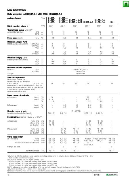
Mini Mini Contactors<br />
Contactors<br />
Data Data according according according to to to IEC IEC IEC 947-5-1, 947-5-1, VDE VDE 0660, 0660, EN EN 60947-5-1 60947-5-1<br />
60947-5-1<br />
Auxiliary Auxiliary Contacts Contacts<br />
Type K1-07D.. K1-07D.. K1-07D..=<br />
K1-07D..=<br />
K1-09D.. K1-09D.. K1-09D..= K1-09D..= K1-07D..= K1-07D..= 24VR 24VR<br />
K1-07L..(=)<br />
K1-07L..(=)<br />
K1-12D.. K1-12D.. K1-12D..= K1-12D..= K1-09D..= K1-09D..= 24VR 24VR K1-09F..(=) K1-09F..(=) K1-09L..(=) K1-09L..(=) HK..<br />
HK..<br />
Rated Rated insulation insulation voltage voltage voltage U U<br />
V AC 690 i 1) 690 1) 690 1) 690 1) 690 2) 690 1)<br />
Thermal Thermal rated rated current current I I to 690V<br />
th th<br />
Ambient temperature 40°C A 10 10 10 10 10 10<br />
60°C A 6 6 6 6 6 6<br />
Power Power loss loss per pole at I W 0,5 0,5 0,5 0,5 0,5 0,5<br />
th<br />
Utilization Utilization category category AC15 AC15<br />
AC15<br />
Rated operational current Ie 220-240V<br />
380-415V<br />
A<br />
A<br />
3<br />
2<br />
3<br />
2<br />
3<br />
2<br />
3<br />
2<br />
3<br />
2<br />
3<br />
2<br />
440V A 1,6 1,6 1,6 1,6 1,6 1,6<br />
500V A 1,2 1,2 1,2 1,2 1,2 1,2<br />
660-690V A 0,6 0,6 0,6 0,6 0,6 0,6<br />
Utilization Utilization category category DC13 DC13<br />
DC13<br />
Rated operational current Ie 60V<br />
110V<br />
A<br />
A<br />
2<br />
0,4<br />
2<br />
0,4<br />
2<br />
0,4<br />
2<br />
0,4<br />
2<br />
0,4<br />
2<br />
0,4<br />
220V A 0,1 0,1 0,1 0,1 0,1 0,1<br />
Maximum Maximum ambient ambient temperature<br />
temperature<br />
Operation open °C -40 to +60 (+90) 3)<br />
enclosed °C -40 to +40<br />
Storage °C -40 to +90<br />
Short Short circuit circuit protection<br />
protection<br />
short-circuit current 1kA,<br />
contact welding not accepted<br />
max. fuse size gL (gG) A 20 20 20 20 20 20<br />
For contactors with thermal overload relay the<br />
device with the smaller admissible control fuse<br />
(contactor or thermal overload relay)<br />
determines the fuse size.<br />
Power Power Power consumption consumption consumption of of coils<br />
coils<br />
AC operated inrush VA 25 - - 25 25 -<br />
sealed VA 4 - 5 - - 4 - 5 4 - 5 -<br />
W 1,2 - - 1,2 1,2 -<br />
DC operated inrush W - 2,5 1,5 2,5 2,5 -<br />
sealed W - 2,5 1,5 2,5 2,5 -<br />
Operation Operation range range of of coils coils<br />
19 - 30V DC<br />
in multiples of control voltage Us 0,85 - 1,1 0,8 - 1,1 0,85 - 1,1 0,85 - 1,1 -<br />
Switching Switching time time time at control voltage U ±10% s<br />
4) 5)<br />
AC operated make time ms 15 - 25 - - 15 - 25 15 - 25 -<br />
release time ms 8 - 25 - - 8 - 25 8 - 25 -<br />
arc duration ms 10 -15 - - 10 -15 10 -15 -<br />
DC operated make time ms - 15 - 19 15 - 19 15 - 19 15 - 19 -<br />
release time ms - 8 - 25 8 - 25 8 - 25 8 - 25 -<br />
arc duration ms - 10 -15 10 -15 10 -15 10 -15 -<br />
Cable Cable cross-section<br />
cross-section<br />
all connectors solid mm2 0,5 - 2,5 0,5 - 2,5 0,5 - 2,5 Fast on Solder connector 0,5 - 2,5<br />
flexible mm2 0,5 - 2,5 0,5 - 2,5 0,5 - 2,5 1x 6,3 x 0,8 Ø 1,15 0,5 - 2,5<br />
flexible with multicore cable end mm2 0,5 - 1,5 0,5 - 1,5 0,5 - 1,5 or<br />
2x 2,8 x 0,8<br />
0,5 - 1,5<br />
Clamps per pole 2 2 2 - - 2<br />
solid or stranded AWG 18 - 14 18 - 14 18 - 14 18 - 14<br />
1) Suitable at 690V for: earthed-neutral systems, overvoltage category I to IV, pollution degree 3 (standard-industry): Uimp = 8kV.<br />
Data for other conditions on request.<br />
2) Suitable at 690V for pollution degree 2, Uimp = 6kV.<br />
Pollution degree 3 U i = 690V non-tracking of the printed circuit CTI ≥600<br />
Pollution degree 3 U i = 500V non-tracking of the printed circuit CTI ≥400<br />
Pollution degree 3 U i = 400V non-tracking of the printed circuit CTI ≥100<br />
3) With reduced control voltage range 0,9 up to 1,0 x U s and with reduced thermal rated current I th to I e /AC15<br />
4) Summary switching time = release time + arc duration<br />
5) Release time of NC make time of NO increase when suppressor units for voltage peak protection are used (Varistor, RC-units, Diode units).<br />
18 D677E