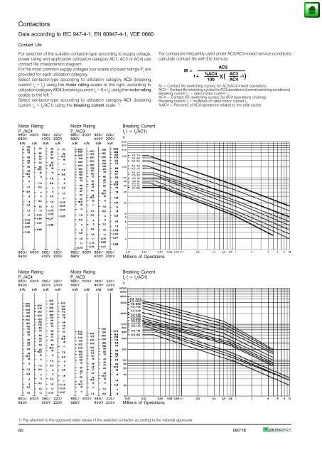
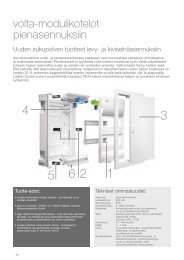
Contactors Data according to IEC 947-4-1, EN 60947-4-1, VDE 0660 Contact Life For selection of the suitable contactor-type according to supply voltage, power rating and application (utilization category AC1, AC3 or AC4) use contact life characteristic diagram. For the most common supply voltages four scales of power ratings P n are provided for each utilization category. Select contactor-type according to utilization category AC3 (breaking current I a = I e ) using the motor rating scales to the right, according to utilization category AC4 (breaking current I a = 6 x I e ) using the motor rating scales to the left. 1) Select contactor-type according to utilization category AC1 (breaking current I a = I e /AC1) using the breaking current scale. 1) Motor Rating Motor Rating Breaking Current P n /AC4 P n /AC3 I a ( = I e /AC1) A Millions of Operations Motor Rating Motor Rating Breaking Current P n /AC4 P n /AC3 I a ( = I e /AC1) A Millions of Operations 1) Pay attention to the approved rated values of the selected contactor according to the national approvals For contactors frequently used under AC3/AC4-mixed service conditions calculate contact life with the formula: AC3 M = %AC4 AC3 1+ -1 100 AC4 x( ) M = Contact life (switching cycles) for AC3/AC4-mixed operations AC3 = Contact life (switching cycles) for AC3 operations (normal switching conditions). Breaking current I a = rated motor current I n . AC4 = Contact life (switching cycles) for AC4 operations (inching). Breaking current I a = multiples of rated motor current I n . %AC4 = Percents of AC4-operations related to the total cycles. 60 D677E
Contactors Utilization Categories For easier choice of devices and in order to make the comparison of different products simplier are utilization categories for contactors and motor-starters according to IEC 947-4-1 and VDE 0660 Part 102, for Type of Cate- Typical applications Rated Test conditions for the number of Test conditions for current gory operational on-load operating cycles making and breaking capacities current Make Break Make Break I/I e U/U e cosϕ I c /I e U r /U e cosϕ I/I e U/U e cosϕ I c /I e U r /U e cosϕ Alter- Non-inductive or nating AC1 slightly inductive loads all values 1 1 0,95 1 1 0,95 1,5 1,05 0,8 1,5 1,05 0,8 Current resistance furnaces Slip-ring motors: AC2 starting, switching off all values 2,5 1 0,65 2,5 1 0,65 4 1,05 0,65 4 1,05 0,65 Squirrel-cage motors: I e ≤ 17A 6 1 0,65 1 0,17 0,65 10 1,05 0,45 8 1,05 0,45 AC3 starting, switching off 17A< I e ≤ 100A 6 1 0,35 1 0,17 0,35 10 1,05 0,45 8 1,05 0,45 motors during running I e > 100A 6 1 0,35 1 0,17 0,35 10 1,05 0,35 8 1,05 0,35 Squirrel-cage motors: I e ≤ 17A 6 1 0,65 6 1 0,65 12 1,05 0,45 10 1,05 0,45 AC4 starting, plugging, 17A< I e ≤ 100A 6 1 0,35 6 1 0,35 12 1,05 0,45 10 1,05 0,45 inching I e > 100A 6 1 0,35 6 1 0,35 12 1,05 0,35 10 1,05 0,35 Switching of electric AC5a discharge lamp controls all values - - - - - - 3 1,05 0,45 3 1,05 0,45 Switching of AC5b incandescent lamps all values - - - - - - 1,5 1,05 1) 4 1,05 1) Switching of AC6a transformers I e ≤ 100A - - - - - - 4,5 1,05 0,45 3,6 1,05 0,45 I e > 100A - - - - - - 4,5 1,05 0,35 3,6 1,05 0,35 Switching of AC6b capacitors - - - - - - - 2) 2) Slightly inductive loads AC7a in household appliances all values - - - - - - 1,5 1,05 0,8 1,5 1,05 0,8 and similar applications AC7b Motor loads for household applications I ≤ e I > e 100A 100A - - - - - - - - - - - - 8 8 1,05 1,05 0,45 0,35 6 6 1,05 1,05 0,45 0,35 Hermetic refrigerant compressor AC8a motor control with manual resetting of overload releases Hermetic refrigerant compressor I ≤ e I > e 100A 100A - - - - - - - - - - - - 6 6 1,05 1,05 0,45 0,35 6 6 1,05 1,05 0,45 0,35 AC8b motor control with automatic resetting of overload releases I ≤ e I > e 100A 100A - - - - - - - - - - - - 6 6 1,05 1,05 0,45 0,35 6 6 1,05 1,05 0,45 0,35 Control of resistive loads and AC12 solid state loads with all values - - - - - - 1 1 0,9 1 1 0.9 isolation by opto couplers Control of AC13 solid state loads with all values - - - - - - 10 1,1 0,65 1,1 1,1 0,65 transformer isolation Control of AC14 small electromagnetic loads - - - - - - - 6 1,1 0,7 6 1,1 0,7 (≤72VA) Control of AC15 electromagnetic load - 10 1 0,7 1 1 0,4 10 1,1 0,3 10 1,1 0,3 (>72VA) Make L/R Break L/R Make L/R Break L/R I/I e U/U e [ms] I c /I e U r /U e [ms] I/I e U/U e [ms] I c /I e U r /U e [ms] Direct Non-inductive or Current DC1 slightly inductive loads all values 1 1 1 1 1 1 1,5 1,05 1 1,5 1,05 1 resistance furnaces Shunt-motors: DC3 starting, plugging, inching all values 2,5 1 2 2,5 1 2 4 1,05 2,5 4 1,05 2,5 dynamic braking of d.c. motors Series-motors: DC5 starting, plugging, inching all values 2,5 1 7,5 2,5 1 7,5 4 1,05 15 4 1,05 15 dynamic braking of d.c. motors Switching of DC6 incandescent lamps all values - - - - - - 1,5 1,05 1) 4 1,05 1) Control of resistive loads and DC12 solid state loads with all values - - - - - - 1 1 1 1 1 1 isolation by opto couplers Control of DC13 electromagnets all values 1 1 ≤300 1 1 ≤300 1,1 1,1 ≤300 1,1 1,1 ≤300 Control of DC14 electromagnetic loads having all values - - - - - - 10 1,1 15 10 1,1 15 economy resistors in circuit U e Rated operational voltage, U Voltage before make, U r Recovery voltage, I e Rated operational current, I Current make, I c Current broken 1) Test with incandescent lamps 2) Test conditions according to standard control circuit devices and switching elements according to IEC 947-5-1 and VDE 0660 Part 200 determind. The table offers different utilization categories, typical applications and assorted test conditions. D677E 61