Index Page General 2 Approvals 3 Technical Information 5 Mounting ...
Index Page General 2 Approvals 3 Technical Information 5 Mounting ...
Index Page General 2 Approvals 3 Technical Information 5 Mounting ...

You also want an ePaper? Increase the reach of your titles
YUMPU automatically turns print PDFs into web optimized ePapers that Google loves.
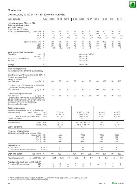
Contactors<br />
Data according to IEC 947-4-1, EN 60947-4-1, VDE 0660<br />
Main Contacts Type K2-09 K2-12 K2-16 K2-23 K2-30 K2-37 K2-45 K2-60 K85 K110<br />
Utilization category DC3 and DC5<br />
Switching of shunt motors<br />
and series motors<br />
Time constant L/R ≤15ms<br />
Rated operational current I e 1 pole 24V A 20 25 25 45 50 50 80 100 150 170<br />
60V A 6 6 6 30 30 30 60 60 85 110<br />
110V A 1,2 1,2 1,2 1,8 1,8 1,8 1,8 1,8 2 2,5<br />
220V A 0,2 0,2 0,2 0,2 0,2 0,2 0,25 0,25 0,5 0,5<br />
3 poles in series 24V A 20 25 25 45 50 50 80 100 150 170<br />
60V A 20 25 25 40 40 40 80 80 100 110<br />
110V A 20 20 20 40 40 40 80 80 100 110<br />
220V A 2,5 2,5 2,5 4 4 4 5 5 7 8<br />
Maximum ambient temperature<br />
Operation open °C -40 to +60 (+90) 1)<br />
enclosed °C -40 to +40<br />
with thermal overload relay open °C -25 to +60<br />
enclosed °C -25 to +40<br />
Storage °C -50 to +90<br />
Short circuit protection<br />
for contactors without thermal overload relay<br />
Coordination-type "1" according to IEC 947-4-1<br />
Contact welding without<br />
hazard of persons<br />
max. fuse size gL (gG) A 63 63 63 80 80 80 160 160 250 250<br />
Coordination-type “2” according to IEC 947-4-1<br />
Light contact welding accepted<br />
max. fuse size gL (gG) A 25 35 35 50 50 50 100 125 160 200<br />
Contact welding not accepted<br />
max. fuse size gL (gG) A 16 16 16 25 35 35 50 63 100 125<br />
For contactors with thermal overload relay the<br />
device with the smaller admissible backup fuse<br />
(contactor or thermal overload relay)<br />
determines the fuse size.<br />
Cable cross-sections<br />
for contactors without thermal overload relay<br />
main connector solid or stranded mm² 0,75 - 4 1,5-10 + 1,5-6 4 - 35 2) 10 - 70 2)<br />
flexible mm² 0,75 - 2,5 1,5-6 + 1,5-4 6 - 25 2) 10 - 70 2)<br />
flexible with multicore cable end mm² 0,5 - 2,5 1,5-6 + 1,5-4 4 - 25 10 - 35<br />
Cables per clamp 2 1+1 1 1<br />
main connector solid AWG 14 - 10 14 - 10 + 14 - 10 10 10<br />
flexible AWG 18 - 10 14 - 8 + 14 - 10 10 - 2 6 - 0<br />
Cables per clamp 2 1+1 1 1<br />
Frequency of operations z<br />
Contactors without thermal overload relay<br />
without load 1/h 10000 7000 7000 3000<br />
AC3, I e 1/h 600 600 400 300<br />
AC4, I e 1/h 120 120 120 120<br />
DC3, I e 1/h 600 600 400 300<br />
Mechanical life<br />
AC operated S x 10 6 10 10 10 5<br />
DC operated with economy resistor S x 10 6 10 10 10 5<br />
Short time current 10s-current A 96 120 144 184 240 296 360 504 680 880<br />
Power loss per pole at I e /AC3 400V W 0,21 0,26 0,4 0,63 1,1 1,7 1,8 3,6 4,3 6,0<br />
Resistance to shock acc. to IEC 68-2-27<br />
Shock time 20ms sine-wave NO g 10 10 10 8 8 8 8 8 7 7<br />
NC g 6 6 6 5 5 5 - - 5 5<br />
1) With reduced control voltage range 0,9 up to 1,0 x U s and with reduced rated current I e /AC1according to I e /AC3<br />
2) Maximum cable cross-section with prepared conductor<br />
56 D677E